

Xylem CL500 User Manual

Global Water
MODBUS MANUAL
For the
CL500
Online Residual
Chlorine Monitor
Global Water
Gold River CA 95670
Phone: 800-876-1172
Fax: 847-672-9988
EMail:Globalw@globalw.com
Website: www.globalw.com
Revised (3/09)
Rev. 1.3
11390 Amalgam Way


1.0 Overview
The Global Water CL500 uses a communication protocol called Modbus. A company
called Modicon, for use with their programmable controllers, developed the Modbus
protocol. Since that time Modbus has evolved into common communication protocol in
industry.
The communication method involves using a master-slave technique, in which there is one
master and several slaves. The CL500 is a slave device. Only the master can initiate
queries. These queries are directed to an individual slave device and the appropriate slave
responds with the requested data.
A broadcast message can be sent to all slaves. The slave devices do not answer these
broadcasts.
There are two transmission modes. These modes are known as RTU (Remote Terminal
Unit) and ASCII (American Standard Code for Information Interchange).
The CL500 can be setup in a network of up to 255 slave devices. Each device must have a
different address (1-255). The CL500 can be set for either RTU or ASCII mode.
CL500 Modbus (3/09)
Rev. 1.3
1
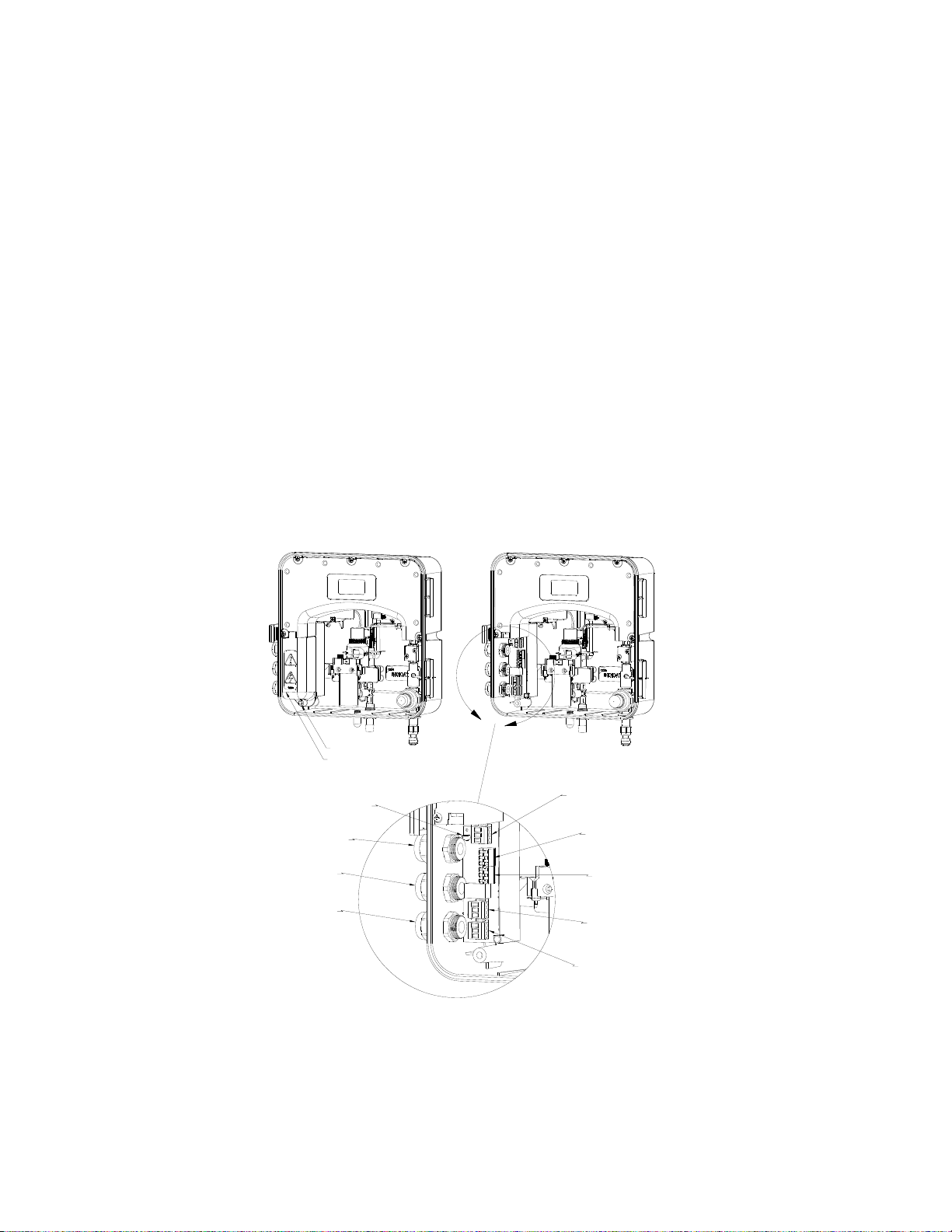
2.0 Electrical Connections
All of the electrical connections to the instrument are made at the termination area, which
is located on the portion of the instrument. The connections are labeled and are selfdescriptive (see Figure 1). Please follow all local and government recommendations and
methods for installation of electrical connections to and between the instrument and other
peripheral devices.
Plugs are inserted into cable bulkheads when shipped, to ensure a watertight seal. These
plugs should be removed and discarded as required when cabling to this connection.
The bulkhead will accept cable diameters from 5.8mm (.230 in.) up to 10 mm (.395 in.).
The terminals are designed to accept wires in the range of 14-28 AWG. All wires should
be stripped to a length of 6 mm
It is the user’s responsibility to assure that the watertight seal is maintained after the
terminal box has been wired for operation. If any of the bulkheads are not tightened
properly around a cable or plug, the ratings of the instrument will be jeopardized and there
is a possibility of creating a shock hazard.
Note: Only qualified electricians should be allowed to perform the installation of the
instrument as it involves a line voltage that could endanger life.
Captive Screw
High Voltage Cover
Power Cable
Strain Relief
Power
Bulkhead
Alarms
Bulkhead
Communication
Bulkhead
Anchor
Power
Terminal
Block
Alarm #2
Terminal
Block
Alarm #1
Terminal
Block
RS-485
Terminal
Block
4-20mA
Terminal
Block
Figure 1: Electrical Connections for the Instrument
CL500 Modbus (3/09)
Rev. 1.3
2

2.1 RS-485 Connection
The RS-485 half-duplex (2-wire) digital interface operates with differential levels that are
not susceptible to electrical interferences. This is why cable lengths up to 3000 ft can be
implemented. The last device on every bus may require a 120-ohm termination resistor to
eliminate the possibilities of signal reflection on the line. Do not run RS-485 cables in the
same conduit as power.
Ensure each instrument is not powered when connecting the RS-485 line. To prevent
damage to the instrument, ensure that power is disconnected prior to making connections.
CL500 Modbus (3/09)
Rev. 1.3
3
 Loading...