

Page 1
INJECTOR
®
MODEL C-1100 MODEL-V
VARIABLE SPEED
POSITIVE DISPLACEMENT INJECTOR PUMP
OPERATING MANUAL
R
Blue-White
Industries, Ltd.
5300 Business Drive
Huntington Beach, CA 92649
Phone: 714-893-8529 FAX: 714-894-9492
E mail: sales@blue-white.com or techsupport@blue-white.com
Website: www.blue-white.com
USA
Page 2

Page 2 C-1100V
TABLE OF CONTENTS
1.....Introduction .....................................................................................3
2.....Specifications ............. .............. ........................................................3
3.....Features........ .............. .............. .............. .............. .............. ..............3
4.....Unpacking.... .............. .............. .............. .............. .............. ..............3
5.....Installation ................. .............. .............. .............. .............. ..............4
5.1..Mounting location ........................... .............. .............. ..............4
5.2..Input power connections ............................... .............. ..............5
5.3..External input signal connections..............................................6
5.4..How to install the tubing and fittings.........................................8
6.....How to operate the Pump ....................... .............. .............. ..............10
6.1..Description of pump output adjustment controls .......................10
6.2..How to adjust the output - manual stroke adjustment .. ..............11
6.3..Mode 1 - Manually Adjusting the output..................... ..............11
6.4..Mode 2 - 4-20 mA input.... .............. .............. ............................12
6.5..Mode 3 - 0-10 VDC input ............... .............. .............. ..............14
6.6..Mode 4 - Frequency (Hz) input ....... .............. .............. ..............16
6.7..Measuring the pump output - Volumetric test .............. ..............18
6.8..FVS Flow Verification System ....... .............. ............................18
7.....How to maintain the Pump ...............................................................20
7.1..Routine inspection and cleaning................................................20
7.2..How to clean the pump ..... ........................................................20
7.3..500 hour service warning timer ....... .............. ............................20
Pump head and Valve exploded view drawing ..... .............. ..............21
Replacement parts drawing ...... .............. .............. .............. ..............22
Replacement parts list ............................ .............. .............. ..............23
Warranty information......................................................... ..............24
Authorized service centers ..................... .............. ............................25
Page 3

C-1100V
1.0 Introduction
Congratulations on purchasing the C-1100 Model-V Variable speed positive
displacement metering pump. The C-1100 is designed to inject chemicals
into piping systems and is capable of injecting against a high system
pressure up to 150 PSI (10.4 bar). In addition to the front mounted
mechanical flow rate adjustment, the C-1100 Model-V unit is equipped with
an external input control circuitry which allows the pumps output to be
externally controlled by either a 4-20mA input signal, a 0-10V DC input
signal or a pulsed input signal.
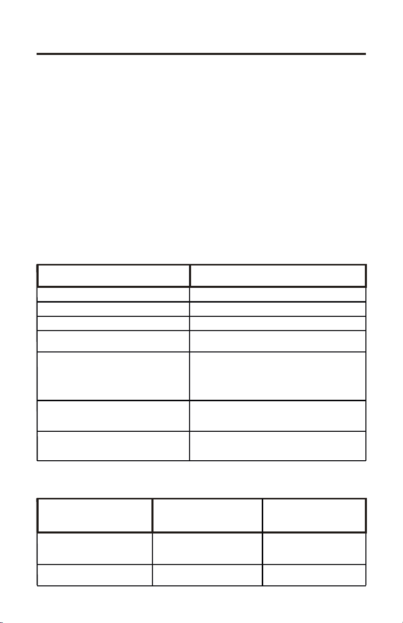
2.0 Specifications
Maximum Working Pressure 150 psig / 10.4 bar (most models)
Maximum Fluid Temperature 130 F / 54 C
Ambient Temperature Range 14 to 110 F / -10 to 43 C
Duty Cycle Continuous
Maximum Viscosity 1,000 Centipoise
Maximum Suction Lift up to 30 ft. water
Power Requirements 108/130Vac 60Hz 40 Watts,
Dimensions 6-1/8” H x 10-1/8” W x 9” D
Weight 12 lb.
o o
o o
208/250Vac 40Hz 40 Watts,
208/250Vac 60Hz 45 Watts
Page 3
3.0 Features
!
Double-ball, springless ceramic check valves with PVDF (Kynar) body,
TFE/P (Aflas) and Viton o-ring seals.
!
Easy access, front mounted mechanical feed rate adjustment.
!
High outlet pressure capability of 150 psig (most models).
!
400:1 adjustment turn down ratio(speed and stroke combined).
!
Digital electronic feed rate control.
!
Corrosion proof Valox housing.
!
Tamper resistant electronic control panel cover.
4.0 Unpacking
Your pump package should contain the following:
1 - Injector pump
1 - suction tube footvalve & strainer assembly
1 - ceramic tubing weight
1 - 5’ Length of clear PVC suction tubing
1 - 5’ Length of opaque LLDPE discharge tubing
1 - Injection fitting with internal back-flow check valve
1 - Mounting hardware kit
Page 4
Page 4
CAUTION: Proper eye and skin protection must be
worn when installing and servicing the pump.
C-1100V
5.0 Installation
CAUTION: Proper eye and skin protection must be
worn when installing and servicing the pump.
Note: All diagrams are strictly for guideline purposes only. Always consult
an expert before installing the pump into specialized systems. The pump
should be serviced by qualified persons only.
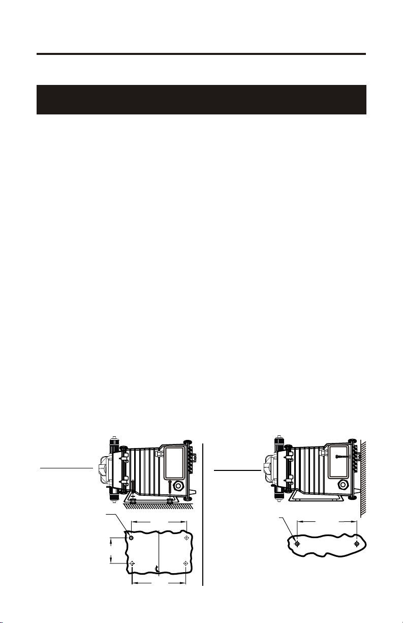
5.1 Mounting Location
Choose an area located near the chemical supply tank, chemical injection
point and electrical supply. Although the pump is designed to withstand
outdoor conditions, a cool, dry, well ventilated location is recommended.
Install the pump where it can be easily serviced.
!
Mount the pump to a secure surface or wall using the enclosed hardware.
Wall mount to a solid surface only. Mounting to drywall with anchors is not
recommended.
!
Mount the pump close to the injection point. Keep the inlet (suction) and
outlet (discharge) tubing as short as possible. Longer discharge tubing
increases the back pressure at the pump tube.
!
Your solution tank should be sturdy. Keep the tank covered to reduce
fumes. Do not mount the pump directly over your tank. Chemical fumes
may damage the unit. Mount the pump off to the side or at a lower level
than the chemical container.
!
Mounting the pump lower than the chemical container will gravity feed the
chemical into the pump. This “flooded suction” installation will aid in
priming the pump and will reduce output error due to increased suction lift.
We recommended installing a shut-off valve, pinch clamp or other means to
halt the gravity feed to the pump during servicing.
!
Be sure your installation does not constitute a cross connection with the
drinking water supply. Check your local plumbing codes.
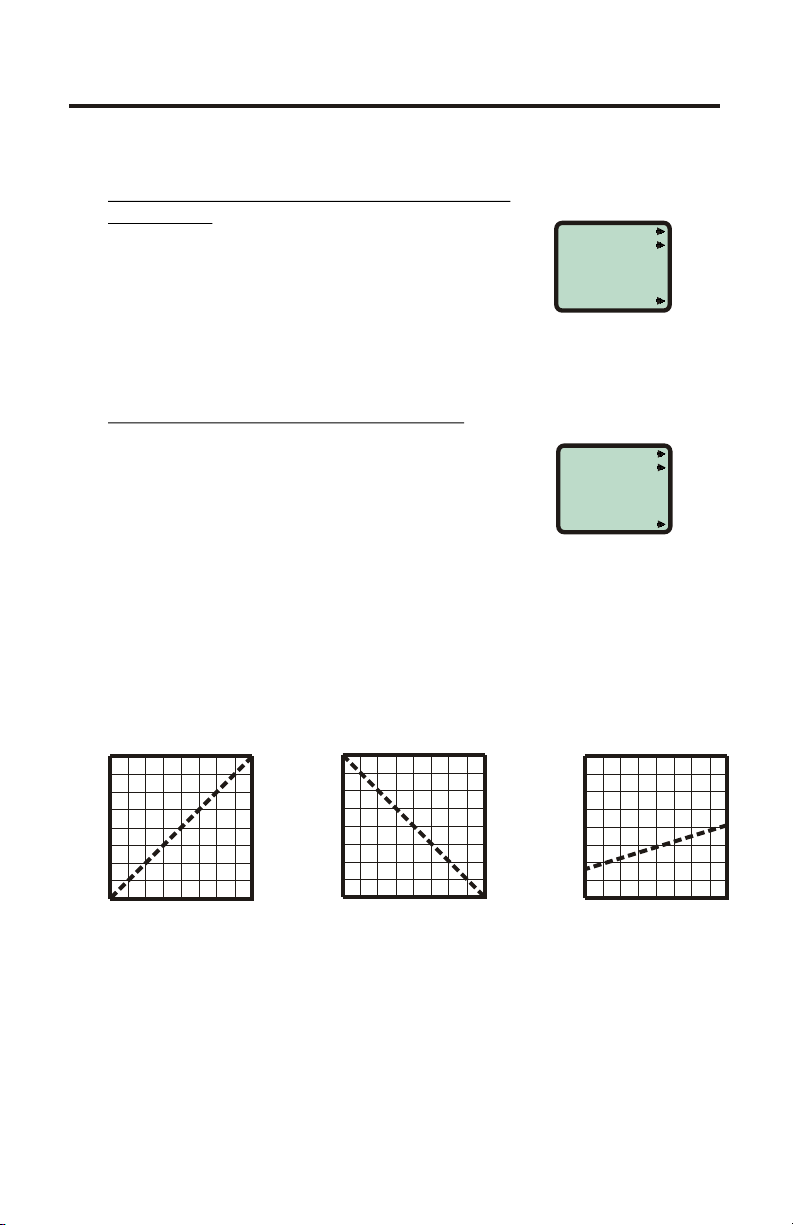
Floor Mount
Drill .156 Dia. (5/32)
For Self-Tap Screw
#10 X 1” Phillips Steel
4 Places
3-1/2”
INJECTOR MOUNTING
Wall Mount
7-5/8”
7-3/8”
Drill .156 Dia. (5/32)
For Self-Tap Screw
#10 X 1” Phillips Steel
Note: For wall-mounting, drill & thread into
solid wood only.
8-3/16”
2 Places
Page 5
WARNING: Risk of electric shock.
C-1100V
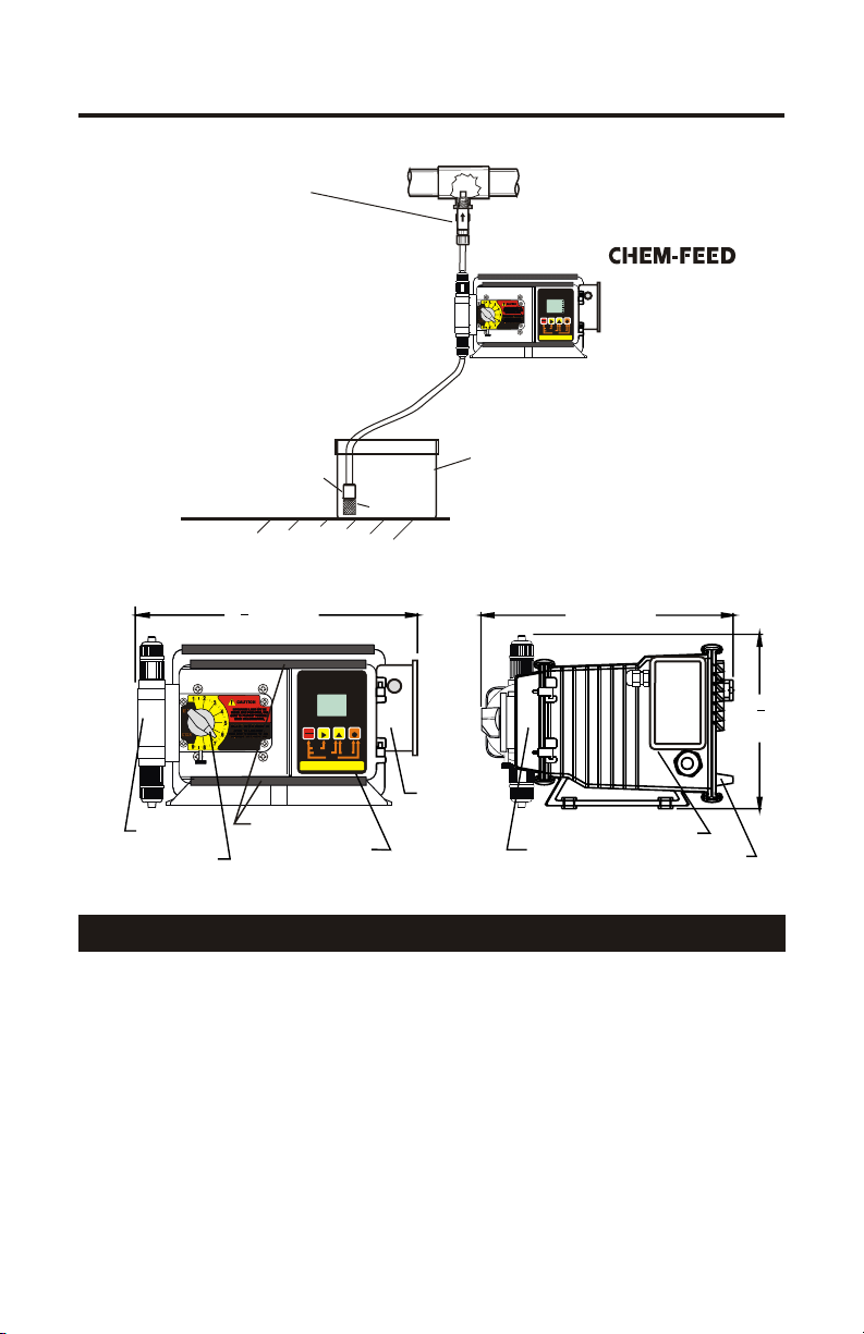
Injection / Check valve
with 1/4” and 1/2” male
pipe threads.
Mount in upward position
to prevent trapped gasses
in the injection fitting.
Pumphead
Adjustment knob
TYPICAL INSTALLATION
Ceramic Weight
1
10 IN. (267 MM)
2
Slide Clamps*
Control Panel
Discharge
Tube
Suction
Tube
Chemical
Container
Strainer
with cover
PARTS LOCATOR DRAWING
VARIABLESPEED PUMP
RUN
1
MODE
PROGRAM
VDC
mA Hz
%SPEED
STAND-BY
PRIME
1000
MINIMUM
ALARM
SERVICE
MAXIMUM
DIGIT MODE
FIELD
RUN
STANDBY
PRIME
DISPLAY
RESETSERVICE
PROGRAM
INPUTMODES
3-0-10VDC 4-PULSE(Hz)
2-4-20mA
1-MANUAL
J-Box
VARIABLESPEEDPUMP
RUN
1
MODE
PROGRAM
VDC
mA Hz
%SPEED
STAND-BY
PRIME
1000
MINIMUM
SERVICE
ALARM
MAXIMUM
DIGIT MODE
FIELD
RUN
STANDBY
PRIME
DISPLAY
RESETSERVICE
PROGRAM
INPUTMODES
3-0-10VDC 4-PULSE(Hz)
2-4-20mA
1-MANUAL
10 IN. (254 MM)
Control Cover
Page 5
®
Wall or shelf mount
away from the top of the
solution tank. Chemical
fumes can damage the
unit.
1
6
4
(159
Motor Housing
Rear Cover
IN.
MM)
5.2 Input Power Connections
WARNING: Risk of electric shock.
! Be certain to connect the pump to the proper supply voltage. Using the
incorrect voltage will damage the pump and may result in injury. The
voltage requirement is printed on the pump serial label.
! Removable resistors on the circuit board are factory preset for the correct
voltage. See page 7 Circuit Board Connections diagram for details.
! The pump is supplied with a ground wire conductor and a grounding type
attachment plug (power cord). To reduce the risk of electric shock, be
certain that the power cord is connected only to a properly grounded,
grounding type receptacle.
Note: When in doubt regarding your electrical installation, contact a
licensed electrician.
Page 6
Page 6
C-1100V
5.3 External Input Signal Connections
The C-1100V will accept any one of three different types of external input
signals; 4-20 mA , 0-10 VDC, or frequency. The 4-20mA and 0-10 VDC
loops must be powered. Two types of frequency inputs, AC sine waves
(magnetic coils type outputs) and Digital Square waves (Hall Effect signals,
contact closures), are acceptable. A jumper plug located on the circuit board
is factory pre-set for AC sine wave signals, the jumper must be repositioned when digital square wave signals are being used. See page 7,
“Hz input jumper settings”
All wiring connections are to be made inside of the junction box located on
the side of the C-1100V. A liquid-tite connector is supplied and should be
used for the external signal cable. The signal input wires are color coded to
the type of signal being used.
SIGNAL INPUT/OUTPUT WIRE COLOR CODES
INPUT TYPE
4-20 mA
0-10 VDC
AC sine wave, TTL, CMOS
CONTACT (10v @ 2 mA max)
HALL EFFECT, NPN
ALARM RELAY
connect 2-conductor plug to either
normally open (NO) (factory default)
or normally closed (NC) side of receptacle.
1 AMP MAX @ 125VAC (24VDC)
FLOW VERIFICATION SENSOR
MOTOR ON SIGNAL
5-20V DC open collector output
closed while motor is energized
ORANGE (+) (non-powered) & BLACK (-)
WIRE COLOR CODE
BLUE (+) (non-powered) & BLACK (-)
WHITE (+) & BLACK (-)
RED (+) & WHITE (-)
PURPLE & PURPLE
RED/WHITE (+ 20VDC)
BLACK (-)
YELLOW (signal)
BROWN (+) & BLACK (-)
PADDLEWHEEL SENSOR SIGNAL INPUT WIRING
BLUE-WHITE
PADDLEWHEEL
SENSOR TYPE
MODEL FH
HALL EFFECT SENSOR
MODEL FC
AC SINE WAVE SENSOR
PADDLEWHEEL SENSOR
WIRE COLOR CODE
RED (+)
BLACK (-)
BARE (signal)
RED (+)
BLACK (-)
PUMP INPUT
WIRE COLOR CODE
RED (+ 20VDC)
BLACK (-)
WHITE (signal)
WHITE (+)
BLACK (-)
Page 7
C-1100V
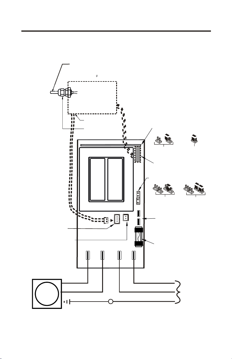
CIRCUIT BOARD CONNECTIONS
EXTERNAL INPUT CABLE
ACCEPTABLE CABLE JACKET RANGE:
YELLOW (verification sensor input)
BROWN (motor-on contact output)
PURPLE X2 (alarm relay contacts)
.118 - .255 INCH
.( 3,0 - 6,5 MM)
RED (+20VDC)
BLACK (Ground)
BLUE (4-20 mA input)
ORANGE (0-10 VDC input)
WHITE (frequency input)
Page 7
ALARM OUTPUT
(CONTACT CLOSURE)
normally open (NO)
(factory default)
TUBE FAILURE SENSOR
PROBE INPUT
2 Grey wires pump head sensors.
RED (+)
DC
MOTOR
BLACK (-)
Ground (green)
JUNCTION BOX
LIQUID-TIGHT
CONNECTOR
MOTOR
MOTOR
BLACK (-)
RED (+)
AC LINE
NEUTRAL
202
C
N
ON
PR BEO
1AMP
250VAC
AC LINE
HOT
Earth Ground (green)
Hz INPUT JUMPER SETTINGS
Located under connector
AC sine waves
Jumper Not Installed
(open - factory default)
INPUT SIGNAL CONNECTOR
Digital square waves
Jumper Installed
7 wire bundle
AC LINE VOLTAGE SETTINGS
0
1
1
0
230 VAC
1
1
One Jumper Installed
on center position
(ends open)
TS
THERMAL SWITCH
.187 push tab connectors
PROTECTOR FUSE
1 Amp, 250 Volt AC
(Littlefuse #239001
or Equivalent)
2 conductors
Two Jumpers Installed
Hot
Common
Input
Power
115 VAC
on end positions
(no open pins)
AC
Page 8
Page 8
CAUTION: Proper eye and skin protection must be
worn when installing and servicing the pump.
C-1100V
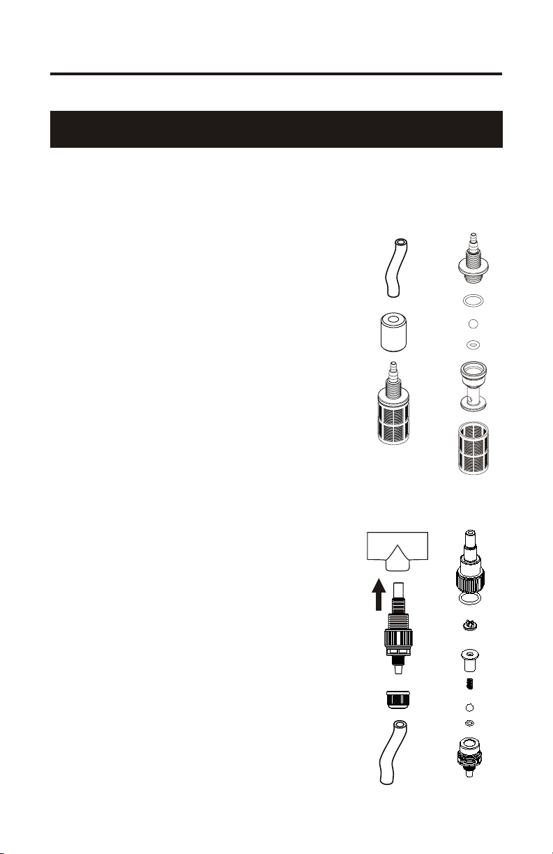
5.4 How To Install the Tubing and Fittings
CAUTION: Proper eye and skin protection must be
worn when installing and servicing the pump.
! Inlet Tubing - Locate the inlet fitting of the pump head. Remove the tube
nut. Push the clear suction tubing through the tube nut and onto the fitting
barb. Hand tighten the tube nut to secure the tubing.
! Footvalve/Strainer - Trim the inlet end
of the suction tubing so that the strainer
will rest approximately two inches from
the bottom of the solution tank. This will
prevent sediment from clogging the
strainer. Slip the ceramic weight over
the end of the suction tube. Press the
strainer’s barbed fitting into the end of
the tube. Secure the ceramic weight to
the strainer. Drop the strainer into the
solution tank.
! Outlet Tubing - Locate the outlet
fitting of the pump head. Remove the
tube nut. Push the opaque discharge
tubing through the tube nut and onto the
compression barb of the fitting. Hand
tighten the tube nut to secure the tubing.
Keep outlet tube as short as possible.
! Injection/Check Valve Fitting
Installation - The Injection/Check valve
fitting is designed to install directly into
either 1/4” or 1/2” female pipe threads.
This fitting will require periodic
cleaning, especially when injecting
fluids that calcify such as sodium
hypochlorite. See section 7.0.
Install the Injection/Check valve directly
into the piping system. To prevent
trapped gasses, install the fitting in an
upward direction. Use Teflon thread
sealing tape on the pipe threads.
Push the opaque outlet (discharge)
tubing through the tube nut and onto the
compression barb of the Injection/Check
valve fitting. Hand tighten the tube nut
to secure the tubing.
FOOTVALVE/STRAINER
Suction Tubing
Ceramic
Wei ght
FootValve
Strainer
Assembly
INJECTION/CHECK VALVE
Pipe tee
Install
upward
Injection
Check valve
Tube retaining
nut
Discharge
Tubing
Page 9
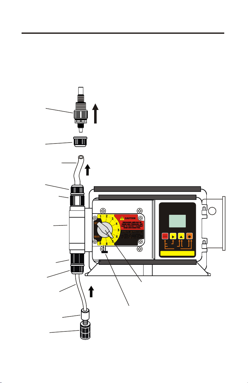
C-1100V
Page 9
Injection
Check valve
Tube Nut
Discharge Tube
(Rigid P.E.)
Tube Nut
Outlet Adapter
Pump Head
Inlet Adapter
Tube Nut
Suction Tubing
(clear PVC)
Install
upward
Manual
Stroke length
Adjustment knob
Lock Screw
VARIABLE SPEED PUMP
MODE
mA Hz
% SPEED
1000
ALARM
FIELD
RUN
STANDBY
PRIME
RESETSERVICE
PROGRAM
INPUTMODES
2-4-20mA
1-MANUAL
RUN
1
PROGRAM
VDC
STAND-BY
PRIME
MINIMUM
SERVICE
MAXIMUM
DIGIT MODE
DISPLAY
3-0-10VDC 4-PULSE(Hz)
Ceramic Weight
Footvalve
Page 10
Page 10
C-1100V
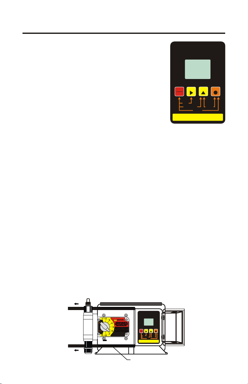
6.0 How To Operate The C-1100V
6.1 Description of Pump Output
Adjustment Controls
panel door by sliding the upper and lower slide
clamps to the left.
!
RUN/STANDBY Button -
4
Press to start and stop the pump. The ARROW
next to the word RUN will light when in the run
mode. The ARROW next to the word STAND-BY
will blink when in the stand-by mode.
4
Press to clear ALARM.
4
When pressed with the FIELD Button, initiates a 99 second prime cycle
which temporarily overrides the mode setting and runs the pump motor at
100% speed. The ARROW next to the word PRIME will blink.
4
When pressed with the DIGIT button, resets the 500 hour service warning
timer to zero.
4
When pressed with the MODE button, initiates the programming mode.
The ARROW next to the word PROGRAM will blink.
!
FIELD Button -
4
In the programming mode, selects the digit to be changed.
4
When pressed with the DIGIT button, initiates the Flow Verification
Sensor feature and allows programming the alarm delay from 1-256
seconds.
!
DIGIT Button -
4
In the programming mode, increases the selected digit.
4
When pressed with the MODE Button, toggles the display from % motor
speed to input signal value.
!
MODE Button -
4
Used to select one of four operating modes.
Mode 1 - Manual Adjustment (external input disabled)
Mode 2 - 4-20mA input
Mode 3 - 0-10VDC input
Mode 4 - Frequency (Hz) input
- Open the control
VARIABLE SPEED PUMP
% SPEED
RUN
STANDBY
PRIME
RESET SERVICE
2 - 4-20mA
1-MANUAL
MODE
VDC
mA Hz
1000
ALARM
SERVICE
DIGIT MODE
FIELD
PROGRAM
INPUT MODES
3 - 0-10VDC 4- PULSE (Hz)
RUN
1
PROGRAM
STAND-BY
PRIME
MINIMUM
MAXIMUM
DISPLAY
VARIABLESPEED PUMP
1
MODE
VDC
mA Hz
%SPEED
1000
ALARM
SERVICE
DIGIT MODE
FIELD
RUN
STANDBY
PRIME
DISPLAY
RESETSERVICE
PROGRAM
INPUTMODES
3-0-10VDC 4-PULSE (Hz)
2-4-20mA
1-MANUAL
SLIDE CLAMP
RUN
PROGRAM
STAND-BY
PRIME
MINIMUM
MAXIMUM
Page 11

C-1100V
Page 11
6.2 How to adjust the output- manual stroke adjustment The
Pump flow rate can be adjusted within a range of 5% -100% of maximum
output (20:1 turndown ration) by means of a mechanical, cam type
mechanism. The mechanism adjusts the pump’s stroke length to an infinite
number of settings within the flow range.
ø Note: The pump’s output will reduce due to increased system pressure,
increased suction lift, and increased fluid viscosity. The pump must be oversized to allow for these factors. Sizing the pump to allow adjustment within
the midrange is preferred to maintain accuracy. Consult the factory for
individual pump model output curve data.
To adjust the pump’s output:
1. With the pump running, loosen the lock screw.
2. Turn the adjustment knob to the desired setting.
3. Re-tighten the lock screw.
6.3 OPERATING MODE 1 - Output adjusted
manually -
In this mode, the pump’s motor speed is adjusted
manually using the front panel touch pad. The motor
speed can be adjusted from 0-100%. To adjust the
speed:
4
Set the pump for mode 1. Press the MODE button
until MODE 1 is shown on the LCD display. The
%SPEED icon will light. The large 3-DIGIT LCD
will indicate the currently programmed percentage of
speed.
4
Enter the programming mode. At the same time,
press the RUN/STANDBY button and the MODE
button. A blinking ARROW will point to the word
PROGRAM indicating the program mode has been
activated.
4
Press the FIELD button to select the digit to program.
The digit will blink when selected.
4
Press the DIGIT button to change the selected digit.
4
Repeat until all digits are programmed.
4
To exit the programming mode, press the
RUN/STANDBY button and the MODE button at the
same time. The arrow next to the word PROGRAM will
disappear.
[
NOTE: If while in the program mode no buttons are
pressed within 20 seconds, the circuitry will automatically return to the run mode, without saving changes.
RUN MODE 1
1
MODE
% SPEED
100
PROGRAM MODE 1
constant speed % setting
1
MODE
% SPEED
000
RUN
PROGRAM
STAND-BY
PRIME
MINIMUM
MAXIMUM
RUN
PROGRAM
STAND-BY
PRIME
MINIMUM
MAXIMUM
Page 12

Page 12
6.4
OPERATING MODE 2 - Output adjusted
by 4-20 mA input signal
-
In this mode, the pump’s motor speed is adjusted
automatically based on the value of the 4-20 mA input
signal. Any motor speed can be assigned to either the
minimum or maximum milliamp input values.
However, the programmed minimum mA value
must be less than the programmed maximum mA
value. The ALARM and SERVICE icons will blink
if the programming is in error. To assign the minimum
and maximum motor speed and the minimum and
maximum mA input signal values:
4
Set the pump for mode 2. Press the MODE button
until MODE 2 is shown on the LCD display. The
%SPEED or mA icon will light depending on the
current display setting. The large 3-DIGIT LCD will
indicate the current motor speed or the current mA
input value.
4
Enter the programming mode. At the same time,
press the RUN/STANDBY and MODE buttons. A
blinking ARROW will point to the word PROGRAM
indicating the program mode is activated. A blinking
ARROW will point to the word MINIMUM indicating
the minimum value is ready to be programmed. The %
SPEED icon will blink indicating the percentage of
speed is ready to be programmed.
4
Enter the motor speed at the minimum mA input
signal value. Press the FIELD button to select the
digit to program. The digit will blink when selected.
4
Press the DIGIT button to change the selected digit.
4
Repeat until all digits are programmed.
4
Press the mode button. The % SPEED icon will stop
blinking and the mA icon will blink indicating the
minimum mA value is ready to be programmed. The
currently programmed minimum value is shown on
the 3-DIGIT LCD.
4
Enter the minimum mA input signal value. Note: this
value must be less than the maximum mA input signal
value. Press the FIELD button to select the digit to
program. The digit will blink when selected.
4
Press the DIGIT button to change the selected digit.
4
Repeat until all digits are programmed.
4
Press the mode button. The Ma icon will stop blinking
and the % SPEED icon will blink. The ARROW next
to the word MAXIMUM will blink indicating the
C-1100V
RUN MODE 2
RUN
2
MODE
mA
04.0
PROGRAM MODE 2
% speed at the minimum input
MODE
% SPEED
000
PROGRAM MODE 2
minimum input value
MODE
mA
04.0
PROGRAM
STAND-BY
PRIME
MINIMUM
MAXIMUM
RUN
2
PROGRAM
STAND-BY
PRIME
MINIMUM
MAXIMUM
RUN
2
PROGRAM
STAND-BY
PRIME
MINIMUM
MAXIMUM
Page 13
C-1100V
4
maximum value is ready to be programmed. The
currently programmed maximum motor speed value is
shown on the 3-DIGIT LCD.
4
Enter the motor speed at the maximum mA input
signal value. Press the FIELD button to select the
digit to program. The digit will blink when selected.
4
Press the DIGIT button to change the selected digit.
4
Repeat until all digits are programmed.
4
Press the mode button. The % SPEED icon will stop
blinking and the mA icon will blink indicating the
maximum mA value is ready to be programmed. The
currently programmed maximum value is shown on
the 3-DIGIT LCD.
4
Enter the maximum mA input signal value. Note: this
value must be greater than the minimum mA input
signal value. Press the FIELD button to select the digit
to program. The digit will blink when selected..
4
Press the DIGIT button to change the selected digit.
4
Repeat until all digits are programmed.
4
Press the mode button. Programming is complete.
4
To exit the programming mode, press the
RUN/STANDBY button and the MODE button at the
same time. The PROGRAM arrow will disappear.
Page 13
PROGRAM MODE 2
% speed at the maximum input
RUN
2
MODE
%SPEED
100
PROGRAM MODE 2
maximum input value
MODE
mA
20.0
PROGRAM
STAND-BY
PRIME
MINIMUM
MAXIMUM
RUN
2
PROGRAM
STAND-BY
PRIME
MINIMUM
MAXIMUM
Example 1
4 mA = 0% OUTPUT
20 mA = 100% OUTPUT
100
75
50
25
Pump Motor Speed (%)
0
6
8
4
10
Milliamp input (mA)
MODE 2 PROGRAMMING EXAMPLES
Example 2
4 mA = 100% OUTPUT
20 mA = 0% OUTPUT
100
75
50
25
Pump Motor Speed (%)
0
6
8
16
20
18
14
12
4
Milliamp input (mA)
16
20
18
14
12
10
Example 4
4 mA = 20% OUTPUT
20 mA = 50% OUTPUT
100
75
50
25
Pump Motor Speed (%)
0
6
8
4
10
Milliamp input (mA)
16
20
18
14
12
Page 14

Page 14
6.5
OPERATING MODE 3 - Output adjusted
by 0-10VDC input signal
-
In this mode, the pump’s motor speed is adjusted
automatically based on the value of the 0-10VDC
input signal. Any motor speed can be assigned to
either the minimum or maximum DC input signal
values. However, the programmed minimum VDC
value must be less than the programmed maximum
VDC value. The ALARM and SERVICE icons will
blink if the programming is in error. To assign the
minimum and maximum motor speed and the
minimum and maximum VDC input signal values:
4
Set the pump for mode 3. Press the MODE button
until MODE 3 is shown on the LCD display. The %
SPEED or VDC icon will light depending on the
current display setting. The large 3-DIGIT LCD will
indicate the current motor speed or the VDC input
value.
4
Enter the programming mode. At the same time,
press the RUN/STANDBY and MODE buttons. A
blinking ARROW will point to the word PROGRAM
indicating the program mode is activated. A blinking
ARROW will point to the word MINIMUM indicating
the minimum value is ready to be programmed. The %
SPEED icon will blink indicating the percentage of
speed is ready to be programmed.
4
Enter the motor speed at the minimum VDC input
signal value. Press the FIELD button to select the
digit to program. The digit will blink when selected.
4
Press the DIGIT button to change the selected digit.
4
Repeat until all digits are programmed.
4
Press the mode button. The % SPEED icon will stop
blinking and the VDC icon will blink indicating the
minimum VDC value is ready to be programmed. The
currently programmed minimum value is shown on
the 3-DIGIT LCD.
4
Enter the minimum VDC input signal value. Note:
this value must be less than the maximum VDC input
signal value. Press the FIELD button to select the digit
to program. The digit will blink when selected.
4
Press the DIGIT button to change the selected digit.
4
Repeat until all digits are programmed.
4
Press the mode button. The VDC icon will stop
blinking and the % SPEED icon will blink. The
ARROW next to the word MAXIMUM will blink
C-1100V
RUN MODE 3
RUN
3
MODE
00.0
PROGRAM MODE 3
% speed at the minimum input
MODE
% SPEED
000
PROGRAM MODE 3
minimum input value
MODE
00.0
VDC
VDC
PROGRAM
STAND-BY
PRIME
MINIMUM
MAXIMUM
RUN
3
PROGRAM
STAND-BY
PRIME
MINIMUM
MAXIMUM
RUN
3
PROGRAM
STAND-BY
PRIME
MINIMUM
MAXIMUM
Page 15

C-1100V
indicating the maximum value is ready to be programmed. The currently programmed maximum
motor speed value is shown on the 3-DIGIT LCD.
4
Enter the motor speed at the maximum VDC input
signal value. Press the FIELD button to select the
digit to program. The digit will blink when selected.
4
Press the DIGIT button to change the selected digit.
4
Repeat until all digits are programmed.
4
Press the mode button. The % SPEED icon will stop
blinking and the VDC icon will blink indicating the
maximum VDC value is ready to be programmed. The
currently programmed maximum value is shown on
the 3-DIGIT LCD.
4
Enter the maximum VDC input signal value. Note:
this value must be greater than the minimum VDC
input signal value. Press the FIELD button to select
the digit to program. The digit will blink when
selected.
4
Press the DIGIT button to change the selected digit.
4
Repeat until all digits are programmed.
4
Press the mode button. Programming is complete.
4
To exit the programming mode, press the
RUN/STANDBY button and the MODE button at the
same time. The PROGRAM arrow will disappear.
Page 15
PROGRAM MODE 3
% speed at the maximum input
RUN
3
MODE
% SPEED
100
PROGRAM MODE 3
maximum input value
MODE
10.0
VDC
PROGRAM
STAND-BY
PRIME
MINIMUM
MAXIMUM
RUN
3
PROGRAM
STAND-BY
PRIME
MINIMUM
MAXIMUM
Page 16

Page 16
6.6
OPERATING MODE 4 - Output adjusted
by frequency (Hz) input signal
-
In this mode, the pump’s motor speed is adjusted
automatically based on the frequency (Hz) of the input
signal. Any motor speed can be assigned to either the
minimum or maximum Hz input signals. However,
the programmed minimum Hz value must be less
than the programmed maximum Hz value. The
ALARM and SERVICE icons will blink if the
programming is in error. To assign the minimum and
maximum motor speed and the minimum and
maximum Hz input signal values:
4
Set the pump for mode 4. Press the MODE button
until MODE 4 is shown on the LCD display. The %
SPEED or Hz icon will light depending on the current
display setting. The large 3-DIGIT LCD will indicate
the current motor speed or the Hz input value.
4
Enter the programming mode. At the same time,
press the RUN/STANDBY and MODE buttons. A
blinking ARROW will point to the word PROGRAM
indicating the program mode is activated. A blinking
ARROW will point to the word MINIMUM indicating
the minimum value is ready to be programmed. The %
SPEED icon will blink indicating the percentage of
speed is ready to be programmed.
4
Enter the motor speed at the minimum Hz input
signal value. Press the FIELD button to select the
digit to program. The digit will blink when selected.
4
Press the DIGIT button to change the selected digit.
4
Repeat until all digits are programmed.
4
Press the mode button. The % SPEED icon will stop
blinking and the Hz icon will blink indicating the
minimum Hz value is ready to be programmed. The
currently programmed minimum value is shown on
the 3-DIGIT LCD.
4
Enter the minimum Hz input signal value (to the
nearest 10 Hz). Note: this value must be less than the
maximum Hz input signal value. Press the FIELD
button to select the digit to program. The digit will
blink when selected.
4
Press the DIGIT button to change the selected digit.
4
Repeat until all digits are programmed.
4
Press the mode button. The Hz icon will stop blinking
and the % SPEED icon will blink. The ARROW next
to the word MAXIMUM will blink indicating the
C-1100V
RUN MODE 4
RUN
4
MODE
000
PROGRAM MODE 4
% speed at the minimum input
MODE
% SPEED
000
PROGRAM MODE 4
minimum input value
MODE
000
PROGRAM
Hz
STAND-BY
PRIME
MINIMUM
MAXIMUM
RUN
4
PROGRAM
STAND-BY
PRIME
MINIMUM
MAXIMUM
RUN
4
PROGRAM
Hz
STAND-BY
PRIME
MINIMUM
MAXIMUM
Page 17

C-1100V
maximum value is ready to be programmed. The
Currently programmed maximum motor speed value is
shown on the 3-DIGIT LCD.
4
Enter the motor speed at the maximum VDC input
signal value. Press the FIELD button to select the
digit to program. The digit will blink when selected.
4
Press the DIGIT button to change the selected digit.
4
Repeat until all digits are programmed.
4
Press the mode button. The % SPEED icon will stop
blinking and the Hz icon will blink indicating the
maximum Hz value is ready to be programmed. The
currently programmed maximum value is shown on
the 3-DIGIT LCD.
4
Enter the maximum Hz input signal value (to the
nearest 10 Hz). Note: this value must be greater than
the minimum Hz input signal value. Press the FIELD
button to select the digit to program. The digit will
blink when selected.
4
Press the DIGIT button to change the selected digit.
4
Repeat until all digits are programmed.
4
Press the mode button. Programming is complete.
4
To exit the programming mode, press the
RUN/STANDBY button and the MODE button at the
same time. The PROGRAM arrow will disappear.
Page 17
PROGRAM MODE 4
% speed at the maximum input
RUN
4
MODE
%SPEED
82.5
PROGRAM MODE 4
minimum input value
MODE
620
PROGRAM
STAND-BY
PRIME
MINIMUM
MAXIMUM
RUN
4
PROGRAM
Hz
STAND-BY
PRIME
MINIMUM
MAXIMUM
MODE 4 PROGRAMMING EXAMPLES
Example 1
0Hz=0%OUTPUT
1000 Hz = 100% OUTPUT
100
75
50
25
Pump Motor Speed (%)
0
0
600
200
400
Frequency input (Hz)
800
1000
Example 2
0 Hz = 100% OUTPUT
1000 Hz = 0% OUTPUT
100
75
50
25
Pump Motor Speed (%)
0
200
0
400
Frequency input (Hz)
600
800
1000
Example 3
0 Hz = 10% OUTPUT
270 Hz = 75% OUTPUT
100
75
50
25
Pump Motor Speed (%)
0
200
0
400
Frequency input (Hz)
600
800
1000
Page 18

Page 18
C-1100V
6.7 Measuring the Pump’s Output - Volumetric Test.
This volumetric test will take into account individual installation factors
such as line pressure, fluid viscosity, suction lift, etc. This test is the most
accurate for measuring the injector’s output in an individual installation.
1. Be sure the Injection Fitting and Footvalve/Strainer is clean and working
properly.
2. Fill a large graduated cylinder with the solution to be injected.
3. With the pump installed under normal operating conditions, place the
suction tubing with the Footvalve/Strainer installed in the graduated
cylinder.
4. Run the pump until all air is removed from the suction line and the solution
enters the discharge tubing. If the pump does not easily prime, remove the
discharge tubing from injection fitting until the pump primes. Re-connect
the discharge tubing to the injection fitting.
5. Remove the suction tubing from the graduated cylinder and refill the
graduated cylinder if necessary. Note the amount of solution in the graduated cylinder.
6. Place suction tubing with the Footvalve/Strainer installed back into the
graduated cylinder.
7. Run the injector for a measured amount of time. A longer testing time will
produce more accurate results.
8. Remove the suction tubing from the graduated cylinder. Measure the
amount of chemical injected.
6.8 FVS - Flow Verification System The C-
1100V is equipped with a Flow Verification System which is designed to
stop the pump and provide a contact closure output in the event the sensor
does not detect chemical during pump operation. This could indicate a
clogged injection fitting, empty chemical solution tank, loose tubing
connection, etc.
To allow the pump to clear any gasses that may have accumulated during
stopper operation (such as with chlorine), an alarm delay time value from 1256 seconds must be programmed (An alarm delay value of 000 seconds
disables the FVS system). The pump will stop, and the alarm mode
activated, if no pulses are received by the pump and the alarm delay time
period has ended. Press the STAND-BY button twice to clear the alarm and
restart the pump. The Flow Verification Sensor is sold as an optional
accessory.
- (sensor sold separately)
Page 19

OPERATING
FLOW RANGE
(ml/min)
C-1100V
Page 19
Confirm the FVS flow range - The Flow
Verification Sensor (FVS) will only function
within its operating range. Sensor model FV100-6V has an operating range of 30-300
ml/min (1-10 oz/min). If the pump’s output is
less than 30 ml/min (0.5 ml/sec), the sensor
will not detect chemical and a signal will not
be sent to the pump.
SENSOR
MODEL
NUMBER
FV-100-6V
FV-200-6V
FV-300-6V
FV-400-6V
FV-500-6V
FV-600-6V
OPERATING
FLOW RANGE
(ml/min)
30-300
100-1000
200-2000
300-3000
500-5000
700-7000
Install the FVS Flow Sensor - The Flow Verification Sensor (FVS) should
be installed on the outlet (discharge) side of the pump head valve. The
sensor includes a PVC tubing insert, located inside the sensor’s female
thread connection, that is designed to seal the sensor onto the pump head
inlet adapter. Thread the sensor onto the pump head until the tubing insert is
snug against the pump head inlet fitting - do not over-tighten.
Connect the red/white, black, and white wires from the sensor to the red,
black, and yellow wires located in the pump’s junction box. See page 7.
FVS Sensor
Insert Tubing Seal
Outlet Adapter
VARIABLESPEED PUMP
RUN
1
MODE
PROGRAM
VDC
mA Hz
%SPEED
STAND-BY
PRIME
1000
MINIMUM
ALARM
SERVICE
MAXIMUM
DIGIT MODE
FIELD
RUN
STANDBY
PRIME
DISPLAY
RESETSERVICE
PROGRAM
INPUTMODES
3-0-10VDC 4- PULSE (Hz)
2-4-20mA
1-MANUAL
Contact Closure Alarm Output - A contact closure output (relay) is
provided with the FVS system. The relay can be configured for normally
open (factory default) or normally closed operation by properly positioning
the connector plug on the circuit board (see page 7).
Page 20

Page 20
CAUTION: Proper eye and skin protection must be
worn when installing and servicing the pump.
C-1100V
7.0 How to Maintain the Pump
CAUTION: Proper eye and skin protection must be
worn when installing and servicing the pump.
7.1 Routine Inspection and Maintenance
The pump requires very little maintenance. However, the pump and all
accessories should be checked regularly. This is especially important when
pumping chemicals. Inspect all components for signs of leaking, swelling,
cracking, discoloration or corrosion. Replace worn or damaged components
immediately.
Cracking, crazing, discoloration and the like during the first week of
operation are signs of severe chemical attack. If this occurs, immediately
remove the chemical from the pump. Determine which parts are being
attacked and replace them with parts that have been manufactured using
more suitable materials. The manufacturer does not assume responsibility
for damage to the pump that has been caused by chemical attack.
7.2 How to Clean the Pump
The pump will require occasional cleaning, especially the Injection fitting,
the Footvalve/Strainer, and the pump head valves. The frequency will
depend on the type and severity of service.
]
Inspect and replace the pumphead valves as required.
]
When changing the diaphragm, the pump head chamber and pump head
cover should be wiped free of any dirt and debris.
]
Periodically clean the injection/check valve assembly, especially when
injecting fluids that calcify such as sodium hypochlorite. These lime
deposits and other build ups can clog the fitting, increase the back pressure
and interfere with the check valve operation. See page 8.
]
Periodically clean the suction strainer. See page 8.
]
Periodically inspect the air vents located under the motor housing and in
the back on the rear housing cover. Clean if necessary.
7.3 500 Hour Service Warning Timer
The pump is equipped with a service warning timer. After approximately
500 hours of accumulated running time, the SERVICE icon will light. This is
a reminder that the pump should be inspected and maintenance performed if
necessary.
Page 21
C-1100V
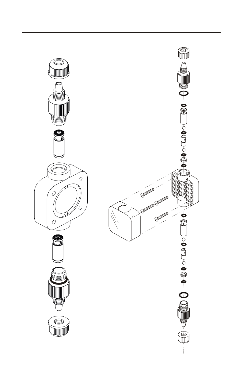
PUMP HEAD AND VALVE EXPLODED VIEW
Page 21
Page 22
Page 22 C-1100V
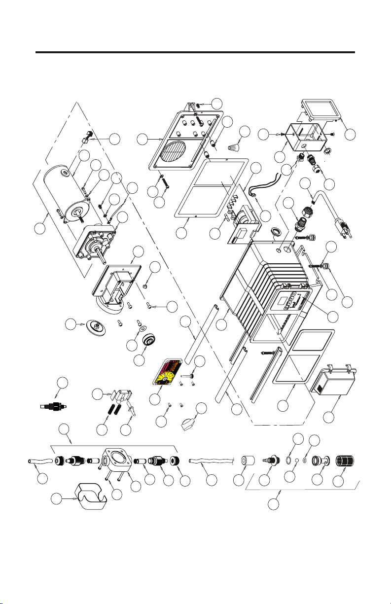
Replacement Parts Drawing
63
61
60
41
62
40
39
38
37
36
35
34
42
33
52
51
59
32
31
30
48
55
49
67
66
56
64
53
65
54
57
52
51
46
68
50
29
28
69
20
16
17
15
19
14
25
18
23
12
13
11
24
22
10
47
9
8
45
44
5
3
4
6
7
2
1
Page 23

PARTS LIST
Page 23C-1100V
Item Part No Description Qty
1 C-345S Screen, FootValve, P.P. 1
2 90002-214 Body, FootValve, PVDF 1
3 2-108A O-ring, FootValve, Aflas 1
2-108E O-ring, FootValve, E.P. 1
4 C-385C Ball, FootValve, Ceramic 1
5 90003-014 O-ring, FootValve, Viton 1
90003-015 O-ring, FootValve, E.P. 1
6 90002-215 Adapter, FootValve, PVDF 1
7 C-340E FootValve, C-340E, EP 1
C-340A FootValve, C-340V, Vit/Aflas1
8 C-346 Ceramic weight, C-346 1
9 C-334-6 Tubing Suction 3/8 x 5 FT 1
10 C-330-6 Tube Nut, .37T, P.P. 2
11 C-560-6V Adapter S/A .37T Viton 2
C-560-6E Adapter S/A .37T EP 2
C-560-6S Adapter S/A .37T Sil 2
12 K-568-4A Cartridge Valve S/A 2
13 C-535 P/Head Noir Molded, P.P. 1
14 C-504HD Screw 10-32 x 1.25 4
15 C-535FC Cover P/Head, 1
16 C-535A6-6 Kit P/Head, 37T Vit/Afl, P-P 1
C-535A6-6E Kit P/Head, 37T E.P. P-P 1
17 C-334-6-10 Tubing D/Charge, 3/8 x 10’ 1
18 C-1505N Offset Cam #1 .125” 1
R-1505N Offset Cam #2 .055” 1
C-1505N-3 Offset Cam #3 .187” 1
C-1505N-4 Offset Cam #4 .100” 1
19 C-1514N Return Spring 2
20 C-1513N Stirrup with slide bearings 1
22 C-1502 Dial Knob 1
23 90011-168 Screw #6 x .62 PH oval ‘A’ 4
24 C-1519N Thumb Screw 6-32 x 1.125 1
25 71000-363 Cover Cam S/A C-1100 1
28 C-1507A Drive Cam S/A #1 .125” 1
R-1507A Drive Cam S/A #2 .055” 1
C-1507-3A Drive Cam S/A #3 .187” 1
C-1507-4A Drive Cam S/A #4 .100” 1
29 A-031 Spacer, Rotor 1
30 C-624N Screw 10-32 x .50 PHL 4
31 90008-138 Plug .312 Hole Black 1
32 76001-183 Motor Mount, Large Dia 1
33 C-406VT-15N Diaphragm 2.0 Vit/TFE 1
C-406T-15N Diaphragm 2.0 EP/TFE 1
34 C-618N-14 Gearbox, 14 RPM 1
C-618N-30 Gearbox, 30 RPM 1
Item Part No Description Qty
C-618N-45 Gearbox, 45 RPM 1
C-618N-60 Gearbox, 60 RPM 1
C-618N-125 Gearbox, 125 RPM 1
C-618N-250 Gearbox, 250 RPM 1
35 90011-078 Washer, Ground, #8 Star 1
36 90010-222 Lead Wire, ground, Green 1
37 90011-024 Screw 8-32 x .25 SL ST 1
38 90011-074 Washer, #8 split-lock 2
39 90011-023 Screw, motor, 8-32 x .50 2
40 90010-244 Motor, 24V DC 1
41 C-1814N-4 Brush kit, (2 pc.) 24V DC 1
42 70002-255 G/motor, 14 Rpm, 24VDC 1
70002-256 G/motor, 30 Rpm, 24VDC 1
70002-257 G/motor, 45 Rpm, 24VDC 1
70002-258 G/motor, 60 Rpm, 24VDC 1
70002-259 G/motor, 125 Rpm, 24VDC 1
70002-260 G/motor, 250 Rpm, 24vDC 1
44 90002-191 Door, Controls Cover 1
45 90006-579 Gasket, Front, Neoprene 1
46 90012-245 Label Timer w/ Ext. Input 1
47 76000-999 Slide Clamp, Front 2
48 76001-000 Slide Clamp, Rear 2
49 76001-253 Enclosure, w/ Ext. Input 1
50 90003-559 Mounting Feet, Rubber 4
51 90011-091 Screw, #10 X 1.0” Phil 6
52 90011-094 Washer, #10 Stainless 6
53 71000-175 Power Cord, 220v50hz, 1
71000-177 Power Cord, 230v60hz, 1
54 70000-589 Connector Liq-tite .375 1
55 90010-235 Fuse, 1A, 250VAC 1
56 A-023N-V-115Circuit board, 115V 1
A-023N-V-230Circuit board, 220V/230V 1
57 90010-246 Wire set w/plug, alarm relay 1
59 90006-580 Gasket, Back Plate 1
60 90010-036 Wire Nut, Blue 2
62 71000-489 Enclosure Back w/Gasket 1
63 90011-044 Screw 6-32 x .37 2
64 90007-515 Bushing, J-Box, Alum. 1
65 90008-199 Connector Liq-tite .187 1
66 76001-254 Junction Box, Input, Valox 1
67 90011-129 Screw, 6-32 X .25 SS 2
68 71000-133 Cover, J-Box w/Gasket, 1
69 A-014N-6A Inj. Valve .37od, ½ lb spring 1
C-395N-6A Inj. Valve .37od, 6lb spring 1
Page 24

Page 24
LIMITED WARRANTY
Your new pump is a quality product and is warranted to be free of defects as set
down in this policy. All parts, including rubberized goods, and labor are covered
under warranty for 90 days from the date of purchase. Used peristaltic pump
tube assemblies are not warranted. Parts, excluding rubberized goods, are
covered under warranty for 12 months from the date of purchase.
Warranty coverage does not include damage to the pump that results from
misuse, carelessness, abuse or alteration. Only the repair or the replacement of
the pump is covered. Blue-White Industries does not assume responsibility for
any other loss or damage.
Warranty status is determined by the pump’s serial label and the sales invoice or
receipt. The serial label must be on the pump and the pump must be
accompanied by the sales invoice or receipt to obtain warranty coverage. The
warranty status of the pump will be verified by Blue-White or a factory
authorized service center.
Please be advised; injection and metering devices are not intended as a means of
treating water to render it suitable for human consumption. When used as
hypochlorinators, they are meant to destroy bacteria and algae contamination,
before it’s removal by filtration. Acid and soda injectors are used for PH control
(balance). Blue-White injectors are factory tested with water only for pressure
and performance. Installers and operators of these devices must be well
informed and aware of the precautions to be taken when injecting various
chemicals -especially those considered hazardous or dangerous.
Should it become necessary to return an injector for repair or service, you must
attach information regarding the chemical used as some residue may be present
within the unit which could be a hazard to service personnel.
Blue-White Industries will not be liable for any damage that may result by the
use of chemicals with their injectors and it’s components. Thank you.
C-1100V
PROCEDURE FOR IN WARRANTY REPAIR
Carefully pack the pump to be repaired, include the foot strainer and
injection/check valve fitting. Enclose a brief description of the problem as well
as the original invoice or sales receipt showing the date of purchase. The receipt
will be returned with the unit. Prepay all shipping costs. COD shipments will
not be accepted. Warranty service must be performed by the factory or an
authorized service center. Damage caused by improper packaging is the
responsibility of the sender.
Page 25

C-1100V
Page 25
AUTHORIZED SERVICE CENTERS
ARKANSAS American Pump
BT Environmental, Inc 7580-A W. Tennessee St. NORTH CAROLINA
Bill Thomason Tallahassee, FL 32304 Southern Industrial Sales
225 Castleberry Street 904-575-9618 1903 Herring Avenue
Hot Springs, AR 71902 Wilson, NC 27893
501-624-3837 919-237-2500
CALIFORNIA (NORTHERN) Del Ray Beach, FL 33444
Howard E. Hutching co.
(Repair Center)
7190 Penryn Plaza
Penryn, CA 95663 814-838-2034
Pool-Tech, Inc. 904-432-9929
3471 Mt. Diablo Blvd.
Lafayette, CA 94549
415-284-1400
Swimco Electric Co. Rapid City, SD 57702
753 Camden Avenue 605-343-7716
Campbell, CA 95008
408-378-2607
CALIFORNIA (SOUTHERN) Pompano Beach, FL 33060
Blue-White Industries
(Repair Center)
5422 Business Drive
Huntington Bch. CA 92649
714-893-8529
COLORADO
Denver Winpump
655 Depew Street
Lakewood, CO 80214-2494
303-233-1121
CONNECTICUT
Cronin-Cook & Associates
24 West Road
Vernon, CT 06066
203-875-0544
FLORIDA
AAA Electric Motor Services
1131 N.E. 45th Street
Ft. Lauderdale, FL 33334
305-772-7501
All American Pool & Patio
2021 Curry Ford Road
Orlando, FL 32806
407-898-8722
Rice Pump & Motor Repair
5788 N. Powerline Road
Ft. Lauderdale FL 33309
305-776-6049
Del Ray Electric
11 N.E. 2nd Avenue
407-278-3976
Jerry Lee Chemical Co.
3407 W. Old Fairfield Drive
Pensacola, FL 32505
Picard Chemical
1670 S. Congress Avenue
W. Palm Beach, FL 33406
407-965-3434
V.J. Mini & Son, Inc.
1581 N. Dixie Highway
305-946-0920
ILLINOIS
Mullarkey Associates
(Repair Center)
12346 S. Keeler Ave. 13700 Hwy. 90 West
Alsip, IL 60658 San Antonio, TX 78245
708-597-5558 512-677-8400
MARYLAND EGCO Industries
Century Pool Service, Inc 8505 Director Row
5020 Nicholson Court, #201 Dallas, TX 75247
Kensington, MD 20895 214-631-6885
301-231-8999
NEVADA Robert Shelton
Swim-In Enterprises, Inc. 1011 Oakmead Drive
1314 S. Main Street Arlington, TX 76011
Las Vegas, NV 89104 817-640-6188
702-384-4223
NEW YORK
Sherwood Specialties, Inc.
412 Smith Street
Rochester, NY 14608
716-546-1211
PENNSYLVANIA
Armor Electric, Inc.
1425 Selinger Avenue
Erie, PA 16505
SOUTH DAKOTA
Son-Aqua Distributing
Jim Robinson
2447 W. Main Street
TENNESSEE
Rock City Machine
307 3rd Avenue South
Nashville, TN 37201
615-244-1371
TEXAS
Alamo Water Refiners
Miracle Water Cond. Co.
Page 26

Page 26
C-1100V
This page blank
Page 27

C-1100V
Page 27
This page blank
Page 28

R
Blue-White
Industries, Ltd.
5300 Business Drive
Huntington Beach, CA 92649
Phone: 714-893-8529 FAX: 714-894-9492
E mail: sales@blue-white.com or techsupport@blue-white.com
Website: www.blue-white.com
# 80000-387 Rev. 3/8/2006
USA
 Loading...