

Page 1
Heat Transfer
BrazedPlate Heat Exchangers
Installation, Operation and Maintenance Manual
Page 2
Installation
FIGURE 1
FIGURE 2
T
Mb
Mv
Evaporators
Refrig. In: ......... F4
Refrig. Out: ...... F1
Liquid In:............ F2
Liquid Out: ......... F3
STEAM TO LIQUID
Condensers
Steam In: ......... F1
Condensate Out: F4
Liquid In:............ F3
Liquid Out: ......... F2
Condensers
REFRIGERATION:
Refrig. In: ......... F1
Refrig. Out: ...... F4
Liquid In:............ F3
Liquid Out: ......... F2
TABLE 4
TABLE 1
of ITT Brazed Plate Heat Exchangers
Upon receipt of the exchanger, inspect for shipping
1.
2.
3.
damage, especially to the connections. If damage is
extensive, notify the carrier immediately. Finally, check the
heat exchanger against proper drawings and spec sheets to
make sure everything is as expected.
Before piping up, inspect all openings in the
heat exchanger for foreign material. Remove all plugs
and shipping covers immediately prior to installing.
Make sure it is thoroughly cleaned to remove all preservation
materials, if any were used, unless the material is soluble in
the system fluid.
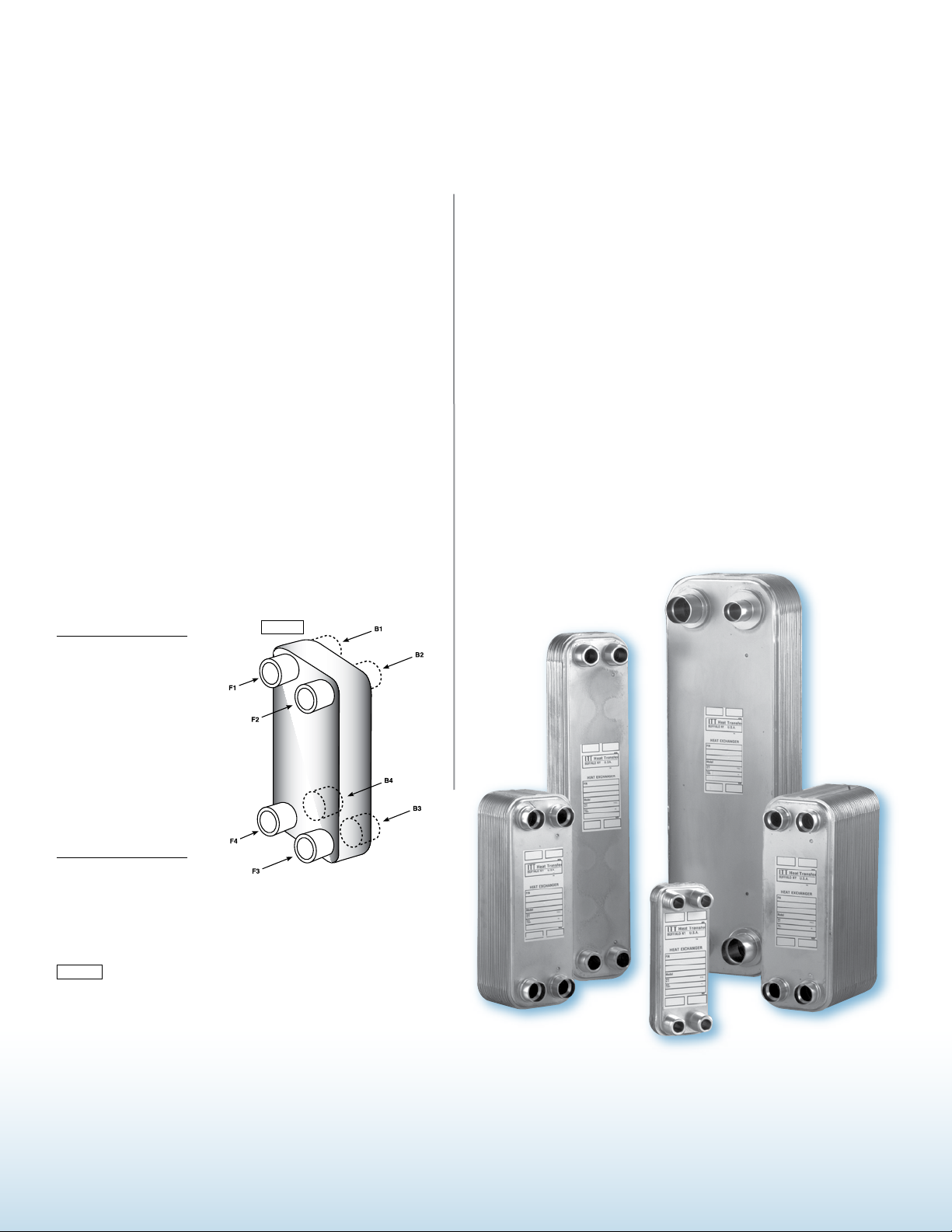
For single phase fluids, the heat exchanger can be
mounted in any orientation that is convenient and
should be piped in a counter current, parallel flow
arrangement. For two phase fluids, the heat exchanger
should be mounted vertically and piped as shown in
Figure 1 and Table 1. Connections may be either on the front
or back of the exchanger.
Provide air vent valves for the heat exchanger so that it
4.
5.
6.
7.
can be purged to prevent or relieve vapor or gas binding.
Install proper relief valves and temperature alarms
to make sure the heat exchanger is not subject to
conditions beyond the intended design.
Do not weld or braze brackets or attachments
directly to body of heat exchanger.
For soldering type connections, braze with minimum
45% silver solder and at maximum 1200° F. For
welded type connections use TIG or MIG welding. Avoid
overheating. A wet cloth or rag should be placed around the
base of the connection. A Nitrogen purge should be used to
avoid internal oxidation. Braze or weld with exchanger in
the vertical position.
CAUTION:
Many Heat exchangers circulate fluids which are irritating or dangerous to the human system.
These fluids could cause problems if bolted or threaded joints are not maintained in a leak tight
condition at operating pressures, temperatures, and no flow, ambient conditions.
Even if fluids are not irritating or dangerous, a leak could cause a slippery situation on the floor below.
Since one fluid in the heat exchanger is at a higher temperature, any leaks may cause burns.
Page 3

FIGURE 2
T
Mb
Mv
F
Liquid Hot Liquid Cold
Gas Hot Liquid Cold
Condensing Gas Hot Liquid Cold
Liquid or Gas Hot Vaporizing Liquid Cold
Start both fluids gradually
at the same time.
Start cold fluid
first then hot fluid.
Start hot fluid first then
slowly start cold fluid.
Avoid temperature shock.
Start hot fluid
first then cold fluid.
Shut down both fluids
gradually at the same time.
Shut down hot fluid
gradually then cold fluid.
Shut down cold fluid
first then hot fluid.
Shut down cold fluid
first then hot fluid.
Type of Fluid Relative Type of Fluid Relative Start-Up Shut-Down
Temperature Temperature Procedure Procedure
TABLE 4
Condensers
REFRIGERATION: STEAM TO LIQUID
Refrig. In: F1
Refrig. Out: F4
Liquid In: F3
Liquid Out: F2
Evaporators
Refrig. In: F4
Refrig. Out: F1
Liquid In: F2
Liquid Out: F3
Evaporators
Refrig. In: ......... F4
Refrig. Out: ...... F1
Liquid In:............ F2
Liquid Out: ......... F3
Condensers
Steam In: F1
Condensate Out: F4
Liquid In: F3
Liquid Out: F2
STEAM TO LIQUID
Condensers
Steam In: ......... F1
Condensate Out: F4
Liquid In:............ F3
Liquid Out: ......... F2
Model T (lbs) F (lbs) Mb (in-lbs) Mv (in-lbs)
400 3327 1798.4 (-1348.8) 327.5 1504.6
410
411 5552.6 1798.4 (-1348.8) 540 1504.6
412
415 5552.6 2158.1 (-1663.5) 540 3407.5
422 24952.8 6069.6 (-4720.8) 6550 8912.7
433 Consult Factory Consult Factory
Start both fluids gradually
at the same time.
Start cold fluid
first then hot fluid.
Start hot fluid first then
slowly start cold fluid.
Avoid temperature shock.
Start hot fluid
first then cold fluid.
Shut down both fluids
gradually at the same time.
Shut down hot fluid
gradually then cold fluid.
Shut down cold fluid
first then hot fluid.
Shut down cold fluid
first then hot fluid.
Temperature Temperature Procedure Procedure
Condensers
REFRIGERATION:
Refrig. In: ......... F1
Refrig. Out: ...... F4
Liquid In:............ F3
Liquid Out: ......... F2
TABLE 2
TABLE 4
435 psig Standard Design
Condensers
REFRIGERATION: STEAM TO LIQUID
Refrig. In: F1
Refrig. Out: F4
Liquid In: F3
Liquid Out: F2
Evaporators
Refrig. In: F4
Refrig. Out: F1
Liquid In: F2
Liquid Out: F3
Evaporators
Refrig. In: ......... F4
Refrig. Out: ...... F1
Liquid In:............ F2
Liquid Out: ......... F3
Condensers
Steam In: F1
Condensate Out: F4
Liquid In: F3
Liquid Out: F2
STEAM TO LIQUID
Condensers
Steam In: ......... F1
Condensate Out: F4
Liquid In:............ F3
Liquid Out: ......... F2
Model T (lbs) F (lbs) Mb (in-lbs) Mv (in-lbs)
400 3327 1798.4 (-1348.8) 327.5 1504.6
410
411 5552.6 1798.4 (-1348.8) 540 1504.6
412
415 5552.6 2158.1 (-1663.5) 540 3407.5
422 24952.8 6069.6 (-4720.8) 6550 8912.7
433 Consult Factory Consult Factory
Model T (lbs) F (lbs) Mb (in-lbs) Mv (in-lbs)
400 200 100 20 200
410
411 280 130 27 300
412
Start both fluids gradually
at the same time.
Start cold fluid
first then hot fluid.
Start hot fluid first then
slowly start cold fluid.
Avoid temperature shock.
Start hot fluid
first then cold fluid.
Shut down both fluids
gradually at the same time.
Shut down hot fluid
gradually then cold fluid.
Shut down cold fluid
first then hot fluid.
Shut down cold fluid
first then hot fluid.
Temperature Temperature Procedure Procedure
Condensers
REFRIGERATION:
Refrig. In: ......... F1
Refrig. Out: ...... F4
Liquid In:............ F3
Liquid Out: ......... F2
TABLE 2
TABLE 4
TABLE 3
The nozzle connections are designed
8.
for normal torque force and damage
may occur if over tightened. The use of pipe
sealant materials compatible with the system
fluids is recommended for threaded type
connections. Connection load limits should be
observed and are shown in Figure 2, Table 2,
and Table 3.
150 psig Pressure Design
Operation
Be sure the entire system is clean
1.
vent plugging of passages with debris.
The use of strainers or settling tanks in
pipelines leading to the heat exchanger
is recommended. The recommended
strainer size is 20-24 mesh.
before starting operation to pre-
2. 3.
Start operating gradually. See
Table 4 for suggested start-up
and shut-down procedures for most
applications. If in doubt, consult the
nearest ITT Heat Transfer representative
for specific instructions.
CAUTION:
A heat exchanger is a pressure vessel designed for operation at certain specific limits of pressure and temperature. The cooling or process system,
which includes the heat exchanger, must be safeguarded with safety valves and controls so that these heat exchanger design conditions are not
exceeded. All operating personnel should be made aware of these specific design pressures and temperatures.
conditions in excess of the specified
design limits shown on the nameplate
attached to the heat exchanger.
4.
corroding.
Do not operate the heat exchanger
under pressure and/or temperature
Drain all fluids when shutting down
to eliminate possible freezing and
Page 4

Maintenance
Clean exchangers subject to
1.
fouling (scale, sludge deposits,
etc.) periodically, depending on specific
conditions. A sludge or scale coating
on the plates can reduce effectiveness.
A marked increase in pressure drop
and/or reduction in performance usually
indicates cleaning is necessary.
Some suggested methods of
3.
cleaning either side of the heat
exchanger are listed below:
n Back flush with a high pressure stream
of hot water to remove loose deposits.
n Circulating hot wash oil or light
distillate will usually effectively remove
sludge or similar soft deposits.
n A 5% solution of Phosphoric Acid or
Ox al ic Acid may be effective in
removing more stubborn deposits.
For optimum results, the solution
should be in a back flush type flow
pattern. Rinse heat exchanger with
cl ean fresh water after use . It is
recommended that the refrigerant
circuit not be chemically cleaned.
A s s u g g e s t e d u n de r
2.
strainer is recommended if the fluid
quality is poor (extensive dirt, debris,
and contaminants). If the fluids are
relatively clean, there should be little
problem with fouling so periodic
cleaning is adequate.
4.
be cleaned by commercial cleaning
methods, then replacement of the unit
is suggested.
“Operation”, the use of a
If the h ea t e xc hange r i s
excessively fouled and it cannot
NO TE : Use in accordance with
the manufacturer’s instructions and
check that cleaning compounds are
compatible with the materials of the
heat exchanger. Since there are a
wide variety of cleaning compounds
av ai la bl e w hi ch are c ompatible
with certain metals and alloys, it
is recommended that you contact a
representative of the above
commercial cleaning products
to determine which particular
cleaning fluid they would
suggest for your type of
scaling problem.
CAUTION:
When the heat exchanger is cleaned, it is
important that full characteristics of the fouling
material and the cleaning agent be known and
care exercised in handling them according to
instructions. Use eye protection to prevent
damage to your eyes. Wear a respirator when
required.
CAUTION:
Do not exceed design conditions of heat
exchanger during operation or maintenance.
CAUTION:
Brazed plate heat exchangers have exposed
sharp metal surfaces. Protective gloves are
recommended during handling.
Warranty
Seller warrants only that it will furnish by freight a replacement for, or at its option
repair, any product of its manufacture or part or portion thereof, proved to its
satisfaction to be defective in material or workmanship under normal use and service
within one (1) year from the date all other equipment or part thereof is first placed
in use, or two (2) years from the date of shipment, whichever shall be less. See ITT
terms and conditions of sale for details.
For m or e in fo rm at io n, pl ea se c on ta ct :
175 Standard Parkway • Cheektowaga, NY 14227
800/447-7700 Fax: 716/897-1777
www.itt.com
Lit# 104-65 (4/07)
© 2007 ITT
Heat Transfer
 Loading...