

Xylem Hoffman Speciality SCC4, Bell&Gosset Hoffman Speciality WC Series, Bell&Gosset Hoffman Speciality WVS Series, Bell&Gosset Hoffman Speciality SCC Series, Hoffman Speciality WC8-20B Instruction Manual
...Page 1
INSTRUCTION MANUAL
DN0156
REVISION H
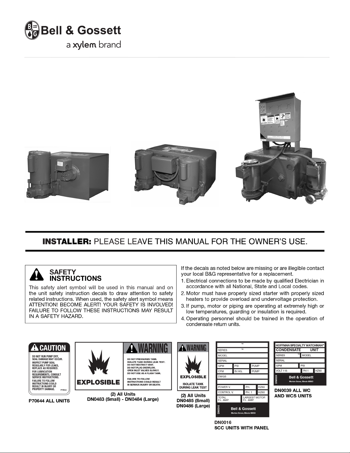
Hoffman Specialty
®
Vented Condensate Units
Watchman Series WC,™ WCS
and Series SCC
WCS Simplex
Watchman® WCS8-20B
™
WC Duplex
Watchman® WCD-12-20BMA
™
SCC4
Page 2
Page 3
3
MOTOR
1
MOTOR
115/1 60*
LINE
L1
L2
FLOAT SWITCH
POWER SUPPLY,
PRIMARY PROTECTION
BY OTHERS
1DW129A 1DW130A
LINE
L2
L1
POWER SUPPLY,
PRIMARY PROTECTION
BY OTHERS
FLOAT SWITCH
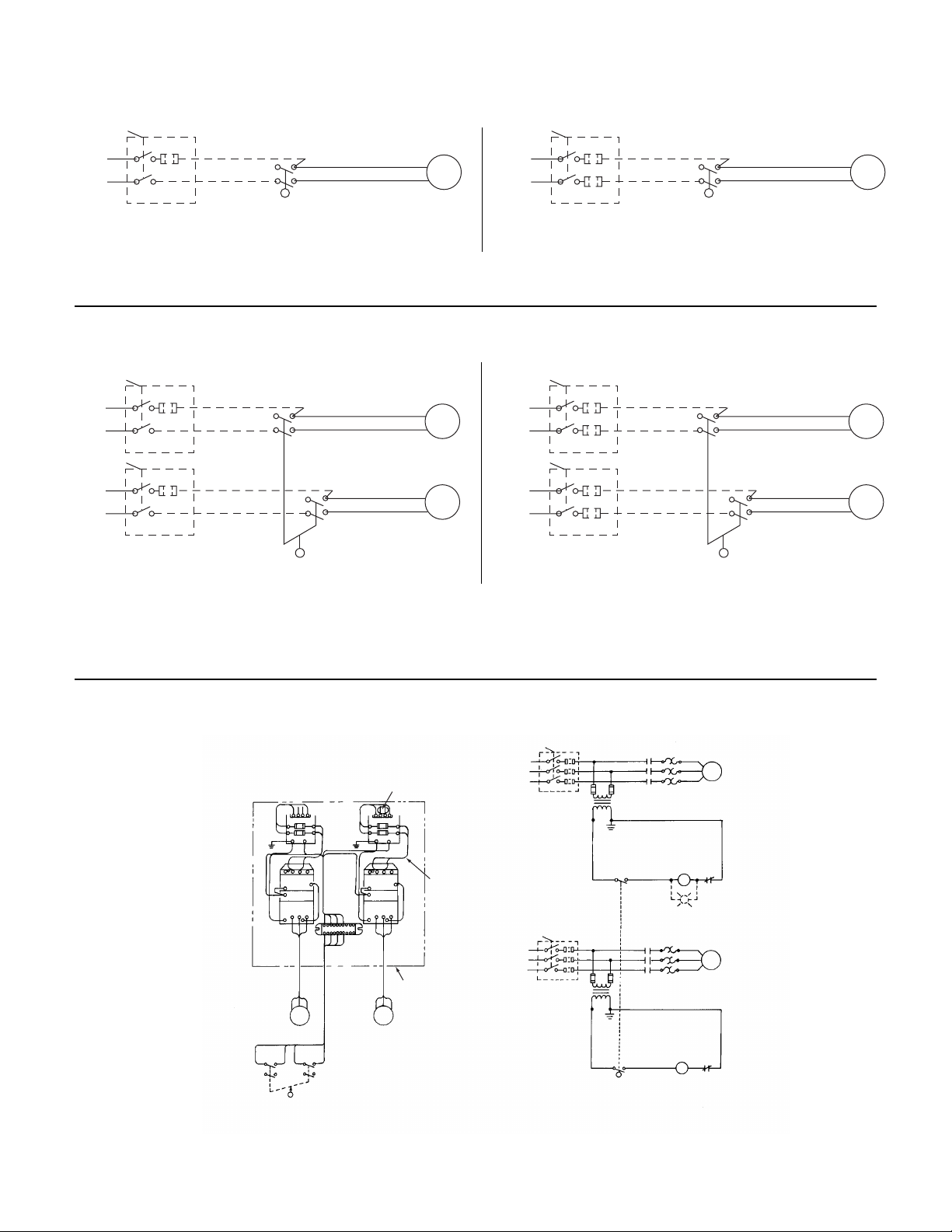
REPRESENTATIVE WIRING DIAGRAMS
WATCHMAN®SIMPLEX UNITS, SINGLE PHASE
WATCHMAN®AND SCC1 DUPLEX UNITS, SINGLE PHASE
FIELD WIRING SHOULD BE IN ACCORDANCE WITH
NATIONAL ELECTRIC CODE.
DASHED LINE WIRING & COMPONENTS BY OTHERS
*230/1/60 VOLTAGE PERMISSIBLE IF MOTOR IS
RECONNECTED PER 'HIGH VOLTAGE' DIAGRAM
ON MOTOR AND APPLICABLE PRIMARY PROTECTION
IS SUPPLIED.
MOTOR
2
MOTOR
1
MOTOR
2
MOTOR
1
115/1/60*
LINE
115/1/60*
LINE
L1
L2
L1
L2
1DW129B 1DW130B
LINELINE
L2
L1
L2
L1
POWER SUPPLY,
PRIMARY PROTECTION
BY OTHERS
POWER SUPPLY,
PRIMARY PROTECTION
BY OTHERS
MECHANICAL
ALTERNATOR
MECHANICAL
ALTERNATOR
FIELD WIRING SHOULD BE IN ACCORDANCE WITH
NATIONAL ELECTRIC CODE.
DASHED LINE WIRING & COMPONENTS BY OTHERS
MODEL SCC2, SCC3 & SCC4 (DUPLEX, 3 PHASE UNITS WITH CONTROL PANEL)
CONNECTION DIAGRAM ELEMENTARY DIAGRAM
LINE
1 H3 H 4
LINE
TRANSFORMER FUSE TYPE
FNQ-R OR EQUIV.
600V / AMP
1
2
MAIN DISCONNECT SWITCH
AND SHORT CIRCUIT
PROTECTION BY OTHERS
FIELD WIRING SHOULD BE IN
ACCORDANCE WITH THE N.E.C.
TRANSF. PRIMARY JUMPER
PER TRANSF. LABEL
1 H3 H 4
L2
L1
L2
L1
GRN
GRN
COIL COIL
COIL
COIL COIL COIL
X1X1X2
X2
H1
H4
H1
H4
11
54 109
5
7
13
3
S2
S1
T1 T2 T3
T1 T2 T3
3
8
4 7 9 12
MOTOR
1
MOTOR
2
MECHANICAL
ALTERNATOR
(AUTOMATIC)
7
4
9
12
ALT.1
ALT.2
ENCLOSURE
FUSE
TRANSF #1
(115 V.A.C. SEC. 1)
MECH.
ALT.
(ALT. 1)
TRANSF. #2
(115 V.A.C. SEC. 1)
FUSE
MECH.
ALT.
(ALT. 2)
MOTOR
2
MOTOR
1
L1
L2
L3
T1
T2
T3
S1
S1
S1
GRN
GRN
X1 X2
X1 X2
L1
L2
L3
T1
T2
T3
S2
S2
S2
S1
S2
10
9
12
13
10
O.L.
O.L.
4
785
5
2DW128
SCC2, SCC3 AND SCC4 UNITS ARE
FACTORY WIRED FOR 230 VOLT,
3 PHASE 60 HERTZ. KITS ARE
AVAILABLE TO CONVERT TO 280V
OR 460 VOLTS.
Page 4
4
PUTTING THE UNIT INTO SERVICE
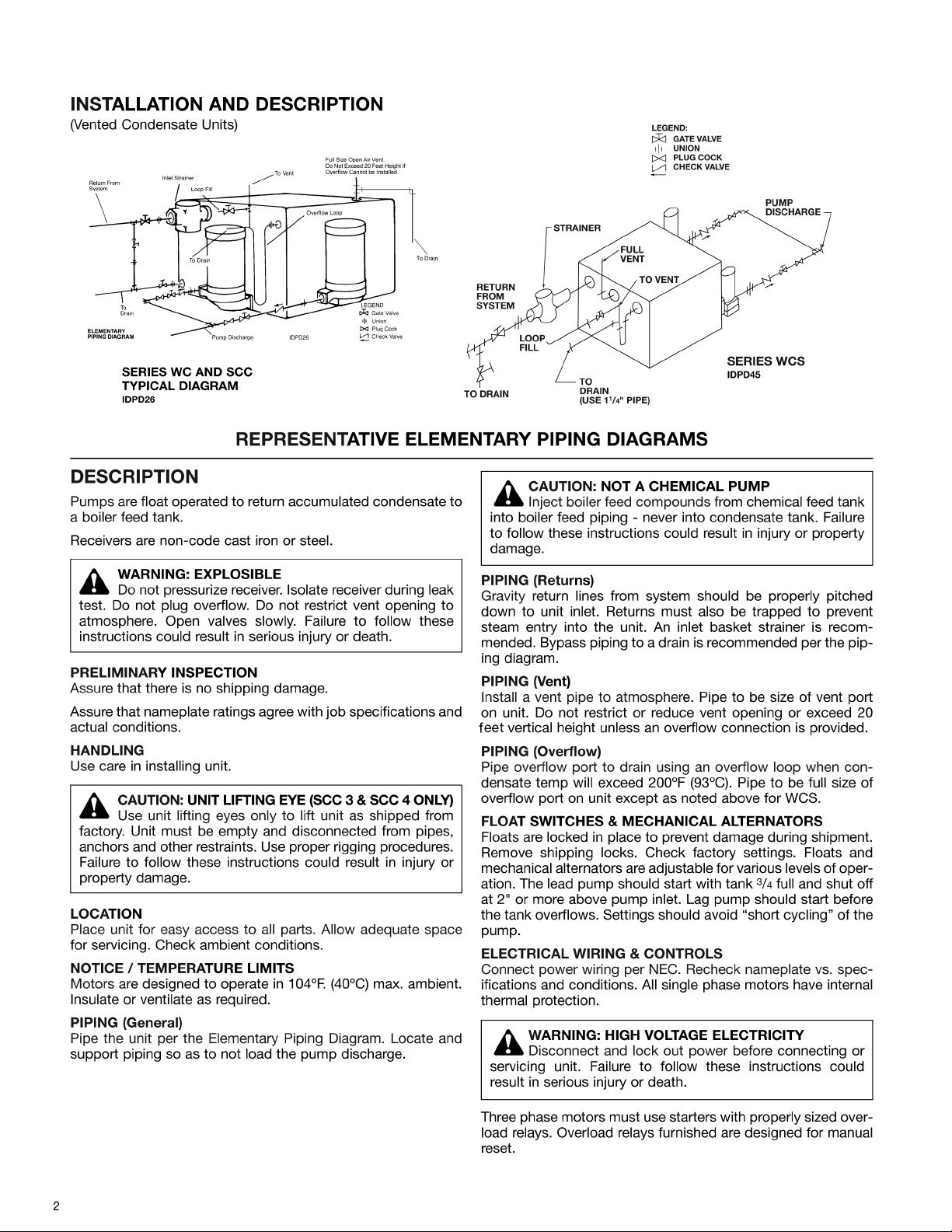
1. Assure that the unit is piped in accordance with instructions
in this manual.
2. Isolate tank before performing any system leak test. Do not
pressurize the tank as part of the leak test. Failure to do this
can result in serious injury or death.
3. Check floats and alternators for free operation.
4. Wire unit per National Electrical Code. See representative
wiring diagrams.
5. Install drain plugs.
6. Fill receiver half full of water to prime pump(s) and prevent
possible damage to pump seals. Avoid freezing conditions
after unit receiver has been filled.
7. Check for proper rotation of all three phase motors.
Rotation must be clockwise looking down on the motor as
indicated by directional arrow on pump casting. If pump
runs backwards, interchange two wires (3 phase only).
8. Throttle plug cock in discharge line until pressure at pump
(while pump is discharging) approaches pump rated pressure. Tighten plug nut to secure adjustment.
9. Remove start-up label (below) from panel (if applicable)
after complying with instructions.
10. If possible, observe operation thru several cycles.
WARNING: EXPLOSIBLE
Do not pressurize receiver. Isolate receiver during leak
test. Do not plug overflow. Do not restrict vent opening to
atmosphere. Open valves slowly. Failure to follow these
instructions could result in serious injury or death.
WARNING: HIGH VOLTAGE
Disconnect and lock out power before connecting or
servicing unit. Failure to follow these instructions could
result in serious injury or death.
CAUTION: DO NOT RUN DRY.
SEAL DAMAGE MAY OCCUR.
Inspect pump seal regularly for leaks. Replace as required.
Failure to follow these instructions could result in injury or
property damage.
CAUTION: DO NOT REVERSE
Reverse operation can cause extensive damage to
pumps. Jog the motor to test for direction of rotation. Failure
to follow these instructions could result in injury or property
damage.
OPERATION AND MAINTENANCE
Operators must be familiar with all sections of this manual to
understand the operation of the unit.
Hot water, steam and electricity can be hazardous.
Check motor nameplate for any lubrication requirements.
Pumps require no lubrication.
NOTICE / AUTO RESTART
Single phase motors will restart automatically after thermal
overload protector trips.
Overload thermal relays in starters must be reset manually.
A properly installed unit should function unattended for long
periods of time. Periodic checks to assure proper operations
are highly recommended. Refer to trouble shooting section
when necessary.
A variety of control options are available and are furnished in
accordance with user specifications. Refer to wiring diagrams
(when furnished) to determine control switch settings.
The inlet strainer (when furnished) is intended to protect the
pump and system. Periodic cleaning should be included in the
maintenance schedule. Check frequently in new systems.
WARNING: EXPLOSIBLE
Do not pressurize receiver. Isolate receiver during leak
test. Do not plug overflow. Do not restrict vent opening to
atmosphere. Open valves slowly. Failure to follow these
instructions could result in serious injury or death.
WARNING: HIGH VOLTAGE
Disconnect and lock out power before connecting or
servicing unit. Failure to follow these instructions could
result in serious injury or death.
CAUTION: SUBSEQUENT DAMAGE
A unit showing symptoms of possible problems
(overflow, noise, leaks, vibrations, continual operation, etc.)
must be corrected immediately. Failure to follow these
instructions may result in full liability for subsequent injury or
property damage.
SAFETY INSTRUCTIONS
SEE COVER OF THIS MANUAL
ELECTRICIAN/INSTALLER/OPERATOR
REMOVE AND DESTROY THIS TAG AFTER —
1. ASSURING THAT ALL PUMPS ROTATE CLOCKWISE PER ARROWS CAST ON VOLUTES. (JOG
PUMP MOMENTARILY TO TEST – INTERCHANGE ANY TWO MOTOR POWER WIRES TO
REVERSE 3PH MOTORS.)
2. ASSURING THAT SHIPPING LOCKS HAVE BEEN REMOVED FROM ALL FLOAT SWITCHES.
Page 5

INSTRUCTIONS
APPLICATION -
For automatically controlling the liquid level in
a closed tank by float movement.
MOUNTING - Screw-in Tank Float Switches are mounted
directly to the tank by means of the 2
1
/2" I.P.S. threaded fitting
(D). Before screwing this fitting into tank, loosen Nut (C) so that
the fitting (D) is free to rotate in the switch bracket. Tighten the
fitting (D) so that there will be no leak past the threads. Then
revolve the switch case until it is horizontal and tighten Nut (C).
REVERSE ACTION - To change, relocate operating link to the
opposite slot in base plate and corresponding hole in adjusting
plate.
ADJUSTMENT - Switches are shipped from the factory set for
a specified float travel. Reasonable adjustment of float travel
can be made in the field by moving adjusting strips (7) which
are held in place by Screws (A) and (B). Loosen Screw (B) and
moving upper adjusting strip (7) will affect the upper limit of
float travel only. Loosening Screw (A) and moving lower adjusting strip (7) will affect the lower limit of float travel.
CAUTION: Switches are shipped with a bracket attached to
the mounting plate. This bracket prevents the float and the rod
from moving in the tank during shipment. When installing the
system, this clearly marked shipping bracket must be removed
and discarded.
5
INSTRUCTIONS
APPLICATION -
Mechanical Alternators serve to open and
close an electric circuit by an upward and downward float
movement. The forces are applied by means of a float operating between different liquid levels. The action is such that two
switch units are alternated on successive cycles. If the liquid
level continues to rise or fall with one pump in operation, the
lever will continue to travel to a further position at which point
the “second” switch will be operated, throwing the stand-by
pump across the line.
MOUNTING - Mechanical alternators are mounted directly to
the tank by means of the 2
1
/2" I.P.S. threaded fitting (D). Before
screwing this fitting into tank, loosen Nut (C) so that the fitting
(D) is free to rotate in the switch bracket. Tighten the fitting (D)
so that there will be no leak past the threads. Then revolve the
switch case until it is horizontal and tighten Nut (C).
STANDARD OPERATION - Contacts are arranged for sump
action. In this form the contacts will close on increase in liquid
level.
REVERSE ACTION - To change, relocate operating link to the
opposite slot in base plate and corresponding hole in adjusting
plate.
ADJUSTMENT - Switches are shipped from the factory set for
a specified float travel. Reasonable adjustment of float travel
can be made in the field by moving adjusting strips (7) which
are held in place by Screws (A) and (B). Loosen Screw (B) and
moving upper adjusting strip (7) will affect the upper limit of
float travel only. Loosening Screw (A) and moving lower adjusting strip (7) will affect the lower limit of float travel.
CAUTION: Switches are shipped with a bracket attached to
the mounting plate. This bracket prevents the float and the rod
from moving in the tank during shipment. When installing the
system, this clearly marked shipping bracket must be removed
and discarded.
TANK FLOAT SWITCH
MECHANICAL ALTERNATOR
Item Number Part
Number Description Required Number
1
Complete Float Switch
1 DA0393
with Float - NEMA 1
4 Float 1 DA0165
7
7
B
A
2
5
1
C
D
4
3
7
7
B
A
2
5
1
C
D
4
3
Item Number Part
Number Description Required Number
1
Complete Mech. Altr.
1 DA0361
with Float - NEMA 1
4 Float 1 DA0165
Page 6

6
These close coupled vertical centrifugal pumps are equipped
with mechanical seals. If system has not been properly cleaned
prior to installation of pump, foreign matter such as dirt, pipe
scale, core sand, etc. may clog the impeller and damage the
seal. A strainer is recommended in return line to pump.
Pump
must not be operated dry.
Seals may be damaged if operated
without water present.
1. Close inlet line gate valve and operate pump momentarily
to remove as much liquid as possible from pump. Close
discharge line gate valve.
2. Shut-off and lock out power.
3. Disconnect wiring to motor.
4. Make sure unit is cool enough that pump can be handled
safely. Open receiver drain to remove remaining liquid.
5. Loosen the motor to pump volute fasteners. Assure that
pressure is relieved per caution note.
6. Remove four capscrews (7) holding volute to motor and lift
motor and impeller out of pump volute.
7. Remove pump/motor assembly and place on work bench.
8. Hold top end of motor shaft with large screwdriver via
screwdriver slot in shaft and back off impeller (counterclockwise) with a rectangular bar or other flat tool inserted
between vanes of the impeller.
9. Remove the rotating part of the mechanical seal from the
end of the shaft.
10. Remove seal holder (2) with stationary ceramic part of
mechanical seal cup rubber from the end of the shaft.
11. Remove stationary ceramic part of mechanical seal and
cup rubber from recess in seal holder.
12. To install new seal proceed as follows: Clean recess in seal
holder thoroughly. Orient motor so that conduit opening on
motor is to the left when looking at motor shaft. Replace
seal holder on the face of the motor maintaining concentricity with motor face. Place new ceramic part of seal in
the cup rubber over motor shaft and press firmly into
recess of seal holder by hand, making certain both parts
bottom evenly. If assembly cannot be bottomed with fingers place a wooden or cardboard tube over shaft onto
ceramic and push into place. Using a clean lint-free cloth,
wipe the mating surfaces of the seal clean of any foreign
matter. Moisten the carbon section of the rotating part of
the seal and place onto the shaft to seat against ceramic.
Place seal spring onto shaft.
13. Hold motor shaft as described in #4 and replace the
impeller on the shaft (clockwise rotation) making sure it is
tight.
14. Orient motor for pump reassembly with conduit opening to
the left. When mounting pump case, discharge should be
90º to the right of the conduit opening on motor. Use care
to insure tight gasket fit to prevent water leakage.
15. Replace four capscrews (7). Tighten down capscrews
evenly to avoid damage.
16. Reconnect pump bleed line (where applicable) and motor
wiring.
17. Close drain and slowly open inlet valves. See warning.
18. Jog to check motor rotation. See caution.
19. Observe operation thru several cycles.
PUMP SERVICE INSTRUCTIONS FOR WATCHMAN “B” DESIGN CENTRIFUGAL PUMPS
CAUTION: HOT SURFACES
Surfaces are hot when system is in operation. Do not
touch hot receiver, let unit cool before servicing. Failure to
follow these instructions could result in injury or property
damage.
WARNING: HIGH VOLTAGE
Disconnect and lock out power before connecting or
servicing unit. Failure to follow these instructions could
result in serious injury or death.
CAUTION: PRESSURIZED SYSTEM
Operating system may contain very hot water under
pressure. Close inlet and open drains before servicing.
When servicing,
loosen screws and move components to
assure pressure is relieved before
removing screws. Keep
drains open during servicing. Failure to follow these instructions could result in injury or property damage.
CAUTION: DO NOT RUN DRY.
SEAL DAMAGE MAY OCCUR.
Inspect pump seal regularly for leaks. Replace as required.
Failure to follow these instructions could result in injury or
property damage.
WARNING: EXPLOSIBLE
Do not pressurize receiver. Isolate receiver during leak
test. Do not plug overflow. Do not restrict vent opening to
atmosphere. Open valves slowly. Failure to follow these
instructions could result in serious injury or death.
CAUTION: DO NOT REVERSE
Reverse operation can cause extensive damage to
pumps. Jog the motor to test for direction of rotation. Failure
to follow these instructions could result in injury or property
damage.
Page 7

7
ITEM NUMBER PART
NUMBER DESCRIPTION REQUIRED NUMBER
1 Motor 1/3 hp. 1ph, 3500 rpm 1 DM0005
2 Seal Holder 1 DP1966
3 Seal* 1 –
4 Impeller 1 DP0321
5 Head Gasket* 1 DG0092
6 Pump Case with Wearing Ring 1 DP1665
7 Capscrew 4 DJ0083
8 Wear Ring 1 DP0482
9 Pipe Plug 1/4" 1 P39040
10 Water Slinger 1 DP0848
Seal Kit including Mechanical
* Seal, Head Gasket & Case to 1 180013
Receiver Gasket
Complete Pump and
Motor Assembly
1 180001
Order Replacement Parts by Description and Part No.
Specify Serial No. shown on nameplate.
1
10
7
3
4
8
6
9
5
2
WATCHMAN “B” DESIGN (FULL MOTOR) PUMP PARTS LIST
Page 8

8
These close coupled vertical centrifugal pumps are equipped
with mechanical seals. If system has not been properly cleaned
prior to installation of pump, foreign matter such as dirt, pipe
scale, core sand, etc. may clog the impeller and damage the
seal. A strainer is recommended in return line to pump.
Pump
must not be operated dry.
Seals may be damaged if operated
without water present.
1. Close inlet line gate valve and operate pump momentarily
to remove as much liquid as possible from pump. Close
discharge line gate valve.
2. Shut-off and lock out power.
3. Disconnect wiring to motor.
4. Make sure unit is cool enough that pump can be handled
safely. Open receiver drain to remove remaining liquid.
5. Loosen the motor to pump volute fasteners. Assure that
pressure is relieved per caution note.
6. Remove three capscrews holding pump head to pump
case and lift motor, pump head and impeller out of pump
case.
7. Hold top end of motor shaft with large screwdriver
or screwdriver socket and back off impeller (counterclockwise) with a rectangular bar or other flat tool inserted
between vanes of the impeller.
8. Remove the rotating part of the mechanical seal from the
end of the shaft.
9. Remove the four thru-bolts holding motor end bell and
stator to pump head, and mark end bell, stator, and pump
head for proper orientation later.
10. Remove pump head and rotor assembly from stator being
careful to keep all belleville washers or finger springs
properly oriented in space above top motor bearing. (On A.
O. Smith motor, rotor will stay with stator and washers are
in lower end of bell.)
11. Remove rotor and lower bearing from pump head. Remove
water slinger from slot in pump head.
12. Remove stationary ceramic part of mechanical seal and
cup rubber from recess in pump head.
13. To install new seal proceed as follows: Clean recess in
pump head thoroughly. Coat recess and outer edge of new
cup rubber with grease. Place new ceramic part of seal in
the cup rubber and press firmly into recess by hand,
making certain both parts bottom evenly. If assembly cannot be bottomed with fingers place cardboard disc on
ceramic and force into place with flat tool.
14. Regrease upper motor bearing with Chevron BRB greases
or equal.
15. Reassemble rotor into pump head and being careful not to
chip or damage ceramic part of seal. Water slinger must
be slipped into recess in head before assembling. A thin
coating of oil or grease on inside edge of hole in slinger will
cause the slinger to slip easily over end of rotor shaft.
16. With the motor vertical, top end bell down, and with
belleville washers or finger springs properly oriented in the
top end bell recess, lower the rotor and head assembly as
a unit, holding it by rotor shaft.
17. Orient the pump head properly and install the thru-bolts.
18. Place motor vertically with pump end up. Do not attempt
assembly of the head and impeller with shaft horizontal.
19. The carbon (rotating) part of the seal should not be loose.
If it is, hold it in place with small amount of grease. Using
a clean, lint-free cloth, wipe the mating surfaces perfectly
clean. Grease rubber lightly and push seal onto shaft so
that the carbon will contact the ceramic seat.
20. Replace the impeller on the shaft (clockwise rotation),
making sure it is tight.
21. Reassemble the unit in reverse order (step 3 thru 1) when
assembling the pump. Use care to insure tight gasket to
prevent water leakage. A new gasket should be ordered
with replacement seal.
22. Close drain and slowly open inlet valves. See warning.
23. Be sure there is adequate water in receiver before operating pump. Allow short period of operation to clear up occasional slight leakage as seal surfaces adjust themselves.
24. Jog to check motor rotation. See caution.
25. Observe operation thru several cycles.
INSTRUCTIONS FOR THE REPLACEMENT OF MECHANICAL SEALS ON
“WATCHMAN” UNIT WITH “A” DESIGN PUMP & MOTOR ASSEMBLIES
CAUTION: HOT SURFACES
Surfaces are hot when system is in operation. Do not
touch hot receiver, let unit cool before servicing. Failure to
follow these instructions could result in injury or property
damage.
WARNING: HIGH VOLTAGE
Disconnect and lock out power before connecting or
servicing unit. Failure to follow these instructions could
result in serious injury or death.
CAUTION: PRESSURIZED SYSTEM
Operating system may contain very hot water under
pressure. Close inlet and open drains before servicing.
When servicing,
loosen screws and move components to
assure pressure is relieved before
removing screws. Keep
drains open during servicing. Failure to follow these instructions could result in injury or property damage.
CAUTION: DO NOT RUN DRY.
SEAL DAMAGE MAY OCCUR.
Inspect pump seal regularly for leaks. Replace as required.
Failure to follow these instructions could result in injury or
property damage.
WARNING: EXPLOSIBLE
Do not pressurize receiver. Isolate receiver during leak
test. Do not plug overflow. Do not restrict vent opening to
atmosphere. Open valves slowly. Failure to follow these
instructions could result in serious injury or death.
CAUTION: DO NOT REVERSE
Reverse operation can cause extensive damage to
pumps. Jog the motor to test for direction of rotation. Failure
to follow these instructions could result in injury or property
damage.
Page 9

ITEM NUMBER PART
NUMBER DESCRIPTION REQUIRED NUMBER
1-5 Motor with Pump Head 1
4 Water Slinger 1 DP0848
5 Pump Head 1 DP0206
7 Head Gasket 1 DG0134
8 Impeller 1 DP0321
9 Case Wearing Ring 1 DP0482
9-10 Pump Case with Wearing Ring 1 DP1602
16 Head to Case Capscrews 3 DJ0077
17 Case to Receiver Gasket 1 DG0060
Seal Kit including Mechanical
Seal, Head Gasket & Case to 1 180013
Receiver Gasket
Complete Pump and
Motor Assembly
1
WATCHMAN “A” DESIGN PUMP AND MOTOR ASSEMBLY
15
14
12
10
16
13
11
17
1
5
2
4
88
6
3
9
7
12
15
14
12
12
3
1
5
10
17
16 13
11
9
8
6
7
2
4
Order Replacement Parts by Description and Part No.
Specify Serial No. shown on nameplate.
9
180061
180060
Page 10

10
Close coupled centrifugal pumps are designed for years of
trouble free service. Units have mechanical shafts seals.
1. Close inlet gate valve and operate pump momentarily to
remove as much liquid as possible from pump. Close discharge line gate valve.
2. Shut-off and lock out power.
3. Make sure unit is cool enough that pump can be handled
safely. Open drain to remove remaining liquid.
4. Carefully remove pump drain plug and bleed line. Wait for
complete drainage.
5. Loosen the motor bracket to pump volute capscrews.
Assure that pressure is relieved per caution note.
6. Complete the removal of the above hardware. Remove
pump/motor assembly and place on work bench.
7. Remove self locking stainless steel capscrews and stainless steel washer (or self locking brass cap nut and washer)
that secure the impeller in place.
8. To remove impeller from motor shaft proceed as follows:
(1) Keyed Shafts. Remove impeller with gear puller or other
means which will not damage impeller or bend motor
shaft.
(2) Threaded Shafts. Hold end of motor shaft opposite
pump with large screwdriver or other suitable tool and
back impeller off with a rectangular bar or other flat tool
inserted between the vanes of the impeller.
9. Remove rotating part of seal from shaft, being careful not to
break carbon face.
10. Remove capscrews holding motor bracket to motor and
remove bracket.
11. Remove stationary part of seal assembly, being careful not
to chip or break ceramic seal.
12. To install seal proceed as follows:
(1) Clean recess in bracket thoroughly. Coat recess and
“rubber” portion of seat with soap solution. Press seat
into recess firmly by hand making certain both parts bottom evenly. If seal cannot be bottomed with fingers
place cardboard shipping disc on ceramic and force into
place with tool.
(2) Carefully place bracket in position on motor shaft with-
out displacing ceramic seat and secure bracket to motor
with capscrews.
(3) Place motor vertically with pump end up. Do not attempt
assembly of seal and impeller with shaft horizontal.
(4) The “carbon” of rotating part of seal should not be loose.
If it is, hold in place with grease. Using clean, lint-free
cloth, wipe mating surfaces perfectly clean. Soap shaft
and push seal onto shaft so that carbon will contact
ceramic seal. If spacer is required, use grease to cause
spacer to adhere to bottom of seal after seal has been
put on shaft. Be sure spacer is on larger diameter of
shaft so that it will not catch between shoulder and
impeller.
13. Replace impeller on shaft. Replace stainless steel washer
and secure impeller with capscrew or cap nut.
14. Place new gasket on pump volute and reassemble motor
and pump subassembly on pump volute.
15. Reconnect pump bleed line and motor wiring.
16. Close drain and slowly open inlet valves. See warning.
17. Jog to check motor rotation. See caution.
18. Observe operation thru several cycles.
PUMP SERVICE INSTRUCTIONS FOR CENTRIFUGAL PUMPS (Other Than “Watchman
®
” Pumps)
Vertical mounting puts motor above floor dirt and water
CAUTION: HOT SURFACES
Surfaces are hot when system is in operation. Do not
touch hot receiver, let unit cool before servicing. Failure to
follow these instructions could result in serious injury or
death.
WARNING: HIGH VOLTAGE
Disconnect and lock out power before connecting or
servicing unit. Failure to follow these instructions could
result in serious injury or death.
CAUTION: PRESSURIZED SYSTEM
Operating system may contain very hot water under
pressure. Close inlet and open drains before servicing.
When servicing,
loosen screws and move components to
assure pressure is relieved before
removing screws. Keep
drains open during servicing. Failure to follow these instructions could result in injury or property damage.
CAUTION: DO NOT RUN DRY.
SEAL DAMAGE MAY OCCUR.
Inspect pump seal regularly for leaks. Replace as required.
Failure to follow these instructions could result in injury or
property damage.
WARNING: EXPLOSIBLE
Do not pressurize receiver. Isolate receiver during leak
test. Do not plug overflow. Do not restrict vent opening to
atmosphere. Open valves slowly. Failure to follow these
instructions could result in serious injury or death.
CAUTION: DO NOT REVERSE
Reverse operation can cause extensive damage to
pumps. Jog the motor to test for direction of rotation. Failure
to follow these instructions could result in injury or property
damage.
Page 11

ITEM NUMBER PART
NUMBER DESCRIPTION REQUIRED NUMBER
1 Motor - Order by Description 1 Consult Factory
2 Impeller 1 Consult Factory
3 Pump Head 1 DP0208
4 Case with Wear Ring 1 DP1603
5 Wearing Ring 1 DP0482
8 Impeller Capscrew 1 DJ0213
9 Impeller Washer 1 DJ0267
10 Capscrews 8 DJ0066
16 Water Slinger 1 DP0848
Seal Kit including Mechanical
6-7
Seal, Head Gasket
1 180014
Case to Receiver Gasket 1 DG0060
616PF PUMP USED ON SCC
1
10
16
3
10
6
7
9
8
4
52
Order Replacement Parts by Description and Part No.
Specify Serial No. shown on nameplate.
11
Page 12

Xylem Inc.
8200 N. Austin Avenue
Morton Grove, Illinois 60053
Phone: (847) 966-3700
Fax: (847) 965-8379
www.xylem.com/bellgossett
Bell & Gossett is a trademark of Xylem Inc. or one of its subsidiaries.
© 2019 Xylem Inc. DN0156H March 2019
 Loading...