

Page 1

Virtex-4 FPGA
www.BDTIC.com/XILINX
Embedded Tri-Mode
Ethernet MAC
User Guide
UG074 (v2.2) February 22, 2010
R
Page 2

R
www.BDTIC.com/XILINX
Xilinx is disclosing this user guide, manual, release note, and/or specification (the "Documentation") to you solely for use in the development
of designs to operate with Xilinx hardware devices. You may not reproduce, distribute, republish, download, display, post, or transmit the
Documentation in any form or by any means including, but not limited to, electronic, mechanical, photocopying, recording, or otherwise,
without the prior written consent of Xilinx. Xilinx expressly disclaims any liability arising out of your use of the Documentation. Xilinx reserves
the right, at its sole discretion, to change the Documentation without notice at any time. Xilinx assumes no obligation to correct any errors
contained in the Documentation, or to advise you of any corrections or updates. Xilinx expressly disclaims any liability in connection with
technical support or assistance that may be provided to you in connection with the Information.
THE DOCUMENTATION IS DISCLOSED TO YOU “AS-IS” WITH NO WARRANTY OF ANY KIND. XILINX MAKES NO OTHER
WARRANTIES, WHETHER EXPRESS, IMPLIED, OR STATUTORY, REGARDING THE DOCUMENTATION, INCLUDING ANY
WARRANTIES OF MERCHANTABILITY, FITNESS FOR A PARTICULAR PURPOSE, OR NONINFRINGEMENT OF THIRD-PARTY
RIGHTS. IN NO EVENT WILL XILINX BE LIABLE FOR ANY CONSEQUENTIAL, INDIRECT, EXEMPLARY, SPECIAL, OR INCIDENTAL
DAMAGES, INCLUDING ANY LOSS OF DATA OR LOST PROFITS, ARISING FROM YOUR USE OF THE DOCUMENTATION.
© 2004–2010 Xilinx, Inc. XILINX, the Xilinx logo, Virtex, Spartan, ISE, and other designated brands included herein are trademarks of Xilinx
in the United States and other countries. PowerPC is a trademark of IBM Corp. and is used under license. All other trademarks are the
property of their respective owners.
Embedded Tri-Mode Ethernet MAC User Guide www.xilinx.com UG074 (v2.2) February 22, 2010
Page 3

Revision History
www.BDTIC.com/XILINX
The following table shows the revision history for this document.
Date Version Revision
11/11/04 1.0 Initial Xilinx release.
07/05/05 1.1 In Chapter 2:
• Revised Tab l e 2-6 , pa g e 23, “Tie-Off Pins,” page 24, and Table 2-10, page 25.
In Chapter 3:
• Revised Ta bl e 3- 6 and Figure 3-5. Added information to “Normal Frame Transmission”.
Revised Figure 3-6, “Client Underrun”, Figure 3-7, and Figure 3-9.
• Added information to “Transmit (TX) Client – 16-bit Wide Interface,” page 43.
• Revised “SGMII/1000BASE-X PCS/PMA,” page 48 and Figure 3-18, page 49, Figure 3-19,
page 49, and Figure 3-21, page 50.
• Added information to “Flow Control Block,” page 57 and the “Flow Control
Implementation Example,” page 60.
• Revised Figure 3-32, page 59.
• Revised “Generic Host Bus,” page 70.
• Revised Table 3-17, page 73, and Table 3-20, page 76.
• Revised Table 3-22, page 78 through Table 3-31, page 83.
•Added “Connecting the MDIO to an External PHY” and Figure 3-49, page 96.
• Revised Ethernet MAC I/Os in Figure 3-55, page 97, Figure 3-60, page 103, Figure 3-65,
page 112, Figure 3-71, page 120, and Figure 3-75, page 128.
• Revised Figure 3-66, page 113.
• Added information to “Auto-Negotiation Interrupt,” page 145.
• Added information to “SGMII Standard,” page 146.
In Chapter 4:
• Revised sample code in “Interfacing to the Processor DCR,” page 150.
In Chapter 5:
•Replaced Figure 5-2, page 154 and Figure 5-3, page 156.
Added Appendix A, “Ethernet MAC Timing Model.”
07/20/05 1.2 Revised figures.
09/07/05 1.3 Corrected items from
“Miscellaneous Functions.” Updated pin 76 in Ta bl e 2 -9 . Revised Figure 3-56, Figure 3-57,
Figure 3-61, Figure 3-63, Figure 3-67, Figure 3-68, Figure 3-72, Figure 5-1, Figure 5-2, and
Figure 5-3. Added “Tri-Mode RGMII v1.3” in Chapter 3. Moved the “Using the DCR Bus as the
Host Bus”, “Description of Ethernet MAC Register Access through the DCR Bus”, and
“Address Code” sections to the “Host Interface” section.
UG074 (v2.2) February 22, 2010 www.xilinx.com Embedded Tri-Mode Ethernet MAC User Guide
version 1.1 and 1.2. Inserted eight new figures into Chapter 5,
Page 4

Date Version Revision
www.BDTIC.com/XILINX
02/07/06 1.4 In Chapter 2, “Ethernet MAC Architecture”:
• Added EMAC#CLIENTRXCLIENTCLKOUT to Tabl e 2 -2, p age 1 9.
In Chapter 5, “Miscellaneous Functions”:
•Corrected “Client RX Data/Control Interface,” page 55.
• Inserted new text to “Length/Type Field Error Checks,” page 52, “Tri-Mode RGMII v2.0,”
page 115, and “10/100/1000 SGMII Clock Management,” page 121.
• Edited waveforms in Figure 3-39, page 66.
• Added sections to Table 3-36, page 88.
•Added “Introduction to MDIO,” page 90, “MDIO Implementation in the EMAC,” page 92,
“Tri-Mode Operation with Byte PHY Enabled (Full-Duplex Only),” page 109, and
“1000BASE-X PCS/PMA (8-bit Data Client) Clock Management,” page 126.
• Added IDELAY component to Figure 3-61, Figure 3-62, Figure 3-63, and Figure 3-64.
• Revised the GT11 block in Figure 3-72 and Figure 3-73. Modified text in “10/100/1000
SGMII Clock Management,” page 121, “8-Bit Data Client,” page 129, and “16-Bit Data
Client,” page 130.
In Chapter 6, “Use Models”:
•Replaced “Interfacing to an FPGA Fabric-Based Statistics Block,” page 154 with new
content.
• Revised example code in “Writing to the PHY Registers Using MDIO,” page 153.
In Chapter 7, “Ethernet MAC Wrappers”:
• Added new text to “VHDL and Verilog CORE Generator Wrappers,” page 159.
•Added “Advanced Clocking,” page 155 and “Client Side Data Width,” page 157 options.
•Replaced “File Generation” with new content.
•Replaced Figure 5-1, page 153.
02/09/06 1.4.1 Cleaned up formatting issues. No content changes.
Embedded Tri-Mode Ethernet MAC User Guide www.xilinx.com UG074 (v2.2) February 22, 2010
Page 5

Date Version Revision
www.BDTIC.com/XILINX
11/11/06 1.5 • Book restructuring of Chapter 3 content:
•
Sections on Host, Client, and MDIO interfaces remain in Chapter 3, now called “Client, Host,
and MDIO Interfaces.”
• Pulled out section on Physical Interface to new Chapter 4, “Physical Interface.”
• Pulled out sections on Clock Frequency Support, Ethernet MAC Configuration, and Auto-
Negotiation Interrupt to new Chapter 5, “Miscellaneous Functions.”
• Globally changed all instances of PHYEMAC#TXD to EMAC#PHYTXD.
•Section “Features” in Chapter 1: Added full-duplex qualifier for SGMII support.
• Ta bl e 3- 3 0: Added EMAC1 registers IRSTATUS, IRENABLE, MIIMWRDATA, and
MIIMCNTL.
• Updated/corrected Figure 3-48, Figure 4-1, Figure 4-3, Figure 4-22, and Figure 4-24.
•Section “SGMII RX Elastic Buffer” added to Chapter 4, “Physical Interface.”
• Corrected section “1 Gb/s RGMII Clock Management” in Chapter 4.
•Section “10/100/1000 SGMII Clock Management” in Chapter 4: The external, high-quality
reference clock for the RocketIO transceiver changed from 125 MHz to 250 MHz. The GT11
clock schemes are simplified as shown in Figure 4-24.
•Section “1000BASE-X PCS/PMA (8-bit Data Client) Clock Management” in Chapter 4: The
GT11 clock schemes are simplified as shown in Figure 4-27.
•Section “1000BASE-X PCS/PMA Clock Management” in Chapter 4: The external, high-
quality reference clock for the 16-bit Data Client MGT changed from 125 MHz to 250 MHz.
The GT11 clock schemes are simplified as shown in Figure 4-28.
• Ta bl e 4- 1 3: Corrected 4.8:7 Pause, 10 and 11 (reversed)
•Section “MGT Elastic Buffer (Ring Buffer)” in Chapter 4: Corrected underflow/overflow
marks, and as a result corrected maximum frame size (Tab le 4 -4 ).
•Section “Transmit Clocking Scheme” in Chapter 5: Corrected description of inputs used to
generate client-side clock.
•Section “Reading the PHY Registers Using MDIO” in Chapter 6: Corrected decode address.
•Section “Writing to the PHY Registers Using MDIO” in Chapter 6: Corrected register
address for EMAC1 Management Configuration; corrected decode address.
• Chapter 7, “Using the Embedded Ethernet MAC” updated.
03/27/07 1.6 • Tab le 2 - 9: Removed Note (1).
• Ta bl e 2- 11 : Revised Note (1).
• Ta bl e 3- 5 : Removed exception from description of Length/Type Out of Range.
• Ta bl e 3- 2 0: Corrected default value for bit 31 (Promiscuous Mode Enable).
• Chapter 4: Multiple revisions in block schematic diagram figures.
• Chapter 4: Former section “1000BASE-X PCS/PMA (8-bit Data Client) Clock Management”
in Chapter 4 incorporated into
• Ta bl e 4- 3 : Consolidated “RISING” and “FALLING” RGMII signals into single signals with
revised descriptions. Added Note (1) to RGMII_TX_CTL_# and RGMII_RX_CTL_#.
UG074 (v2.2) February 22, 2010 www.xilinx.com Embedded Tri-Mode Ethernet MAC User Guide
section “8-Bit Data Client.”
Page 6

Date Version Revision
www.BDTIC.com/XILINX
08/20/07 1.7 • Replaced screen shots with updated images from v4.5 software.
• Ta bl e 2- 11 : Revised description of TIEEMAC#CONFIGVEC[63].
•Section “Length/Type Field Error Checks” in Chapter 3: Numerous textual revisions
throughout this section.
•Section “Receiving a PAUSE Control Frame” in Chapter 3: Last paragraph revised.
• Ta bl e 3- 9 : Revised definition of Receiver Configuration register bit [25] (LT_DIS).
• Figure 4-7 through Figure 4-10 and Figure 4-12 through Figure 4-16 and accompanying
text: Added IDELAY element to clock input.
• Figure 4-24: Corrected placement of BUFG to TXCLIENTCLKOUT.
• Made other typographical edits.
02/06/08 1.8 • Added conditions causing assertion of EMAC#CLIENTRXBADFRAME to “Frame
Reception with Errors,” page 53.
• Rewrote description of ALIGNMENT_ERROR bit in Tab l e 3-5 , pag e 70.
• Updated Figure 4-28, page 139.
•Added “Core Latency” in Appendix A.
08/13/08 1.9 • Corrected transposition error in the description column for bit [1] in Table 3-13, page 78
(values 0 and 1 were switched in second sentence).
• Corrected transposition error in the description column for bits 5.8:7 in Table 4-14, page 144
(values 01 and 10 were switched).
• Rewrote item number 1 for 1000BASE-X auto-negotiation summary (“Overview of
Operation,” page 151).
• Updated the link in the first bullet of “Global Buffer Usage,” page 165.
05/12/09 2.0 • Chapter 4:
In sections “1 Gb/s GMII Only,” page 107, “Tri-Mode Operation,” page 109, “Tri-
Mode Operation with Byte PHY Enabled (Full-Duplex Only),” page 110, “1 Gb/s
RGMII Clock Management,” page 115, “Tri-Mode RGMII v2.0,” page 117, and “Tri-
Mode RGMII v1.3,” page 120, changed the description of the method used to delay
the received clock (GMII_RX_CLK in case of GMII and RGMII_RXC in case of
RGMII) with respect to data. Original method described use of IDELAY and BUFG.
Revised method describes use of a DCM and BUFG.
In Figure 4-7, page 107, Figure 4-8, page 108, Figure 4-9, page 110, Figure 4-10,
page 111, Figure 4-12, page 115, Figure 4-13, page 116, Figure 4-14, page 118,
Figure 4-15, page 119, Figure 4-16, page 121, and “16-Bit Data Client,” page 139,
Replaced IDELAY block in clock path with DCM.
• Chapter 6:
“Simulation Models,” page 155: Removed description of SmartModels. Replaced
references to SmartModel with references to SecureIP throughout this section. Added
“SecureIP Model,” page 155.
• Chapter 7:
Removed content discussing Ethernet MAC wrappers and replaced it with“Using the
Embedded Ethernet MAC,” page 167.
Embedded Tri-Mode Ethernet MAC User Guide www.xilinx.com UG074 (v2.2) February 22, 2010
Page 7

Date Version Revision
www.BDTIC.com/XILINX
10/28/09 2.1 • Chapter 2:
Updated the description of TIEEMAC#CONFIGVEC[62] and
TIEEMAC#CONFIGVEC[61] Table 2-11, page 30 with the full-duplex mode
requirement.
• Chapter 3:
Updated“IFG Adjustment,” page 46 and “Flow Control Block,” page 61 with the fullduplex mode requirement.
02/22/10 2.2 • Chapter 4:
• Replaced EMAC#CLIENTTXGMIIMIICLKOUT with GTX_CLK in “Tri-Mode
Operation,” page 109.
• Updated BUFGMUX and GTX_CLK in upper portion of Figure 4-9, page 110.
• Updated description of Link Status and added table note to Table 4-11, page 141.
• Appendix A:
Changed T
page 171.
xMACWL
to Clock Low and T
xMACWH
to Clock High in Figure A-1,
UG074 (v2.2) February 22, 2010 www.xilinx.com Embedded Tri-Mode Ethernet MAC User Guide
Page 8

Embedded Tri-Mode Ethernet MAC User Guide www.xilinx.com UG074 (v2.2) February 22, 2010
www.BDTIC.com/XILINX
Page 9

Table of Contents
www.BDTIC.com/XILINX
Revision History . . . . . . . . . . . . . . . . . . . . . . . . . . . . . . . . . . . . . . . . . . . . . . . . . . . . . . . . . . . . . 3
Preface: About This Guide
Guide Contents . . . . . . . . . . . . . . . . . . . . . . . . . . . . . . . . . . . . . . . . . . . . . . . . . . . . . . . . . . . . . 13
Additional Resources . . . . . . . . . . . . . . . . . . . . . . . . . . . . . . . . . . . . . . . . . . . . . . . . . . . . . . . 13
Conventions . . . . . . . . . . . . . . . . . . . . . . . . . . . . . . . . . . . . . . . . . . . . . . . . . . . . . . . . . . . . . . . . 14
Typographical. . . . . . . . . . . . . . . . . . . . . . . . . . . . . . . . . . . . . . . . . . . . . . . . . . . . . . . . . . . . 14
Online Document . . . . . . . . . . . . . . . . . . . . . . . . . . . . . . . . . . . . . . . . . . . . . . . . . . . . . . . . . 14
Chapter 1: Introduction
Ethernet MAC Overview . . . . . . . . . . . . . . . . . . . . . . . . . . . . . . . . . . . . . . . . . . . . . . . . . . . . 15
Features. . . . . . . . . . . . . . . . . . . . . . . . . . . . . . . . . . . . . . . . . . . . . . . . . . . . . . . . . . . . . . . . . . . . . 16
Chapter 2: Ethernet MAC Architecture
Architecture Overview . . . . . . . . . . . . . . . . . . . . . . . . . . . . . . . . . . . . . . . . . . . . . . . . . . . . . . 17
Ethernet MAC Primitive. . . . . . . . . . . . . . . . . . . . . . . . . . . . . . . . . . . . . . . . . . . . . . . . . . . . . 20
Ethernet MAC Signal Descriptions . . . . . . . . . . . . . . . . . . . . . . . . . . . . . . . . . . . . . . . . . . 22
Client Signals . . . . . . . . . . . . . . . . . . . . . . . . . . . . . . . . . . . . . . . . . . . . . . . . . . . . . . . . . . . . 22
Clock Signals . . . . . . . . . . . . . . . . . . . . . . . . . . . . . . . . . . . . . . . . . . . . . . . . . . . . . . . . . . . . . 25
Host Interface Signals . . . . . . . . . . . . . . . . . . . . . . . . . . . . . . . . . . . . . . . . . . . . . . . . . . . . . 26
Reset and CLIENTEMAC#DCMLOCKED Signals . . . . . . . . . . . . . . . . . . . . . . . . . . . . . 27
Tie-Off Pins . . . . . . . . . . . . . . . . . . . . . . . . . . . . . . . . . . . . . . . . . . . . . . . . . . . . . . . . . . . . . . 28
Management Data Input/Output (MDIO) Interface Signals . . . . . . . . . . . . . . . . . . . . 32
Mode-Dependent Signals . . . . . . . . . . . . . . . . . . . . . . . . . . . . . . . . . . . . . . . . . . . . . . . . . . 32
RocketIO Multi-Gigabit Transceiver Signals . . . . . . . . . . . . . . . . . . . . . . . . . . . . . . . . . . 34
Chapter 3: Client, Host, and MDIO Interfaces
Client Interface . . . . . . . . . . . . . . . . . . . . . . . . . . . . . . . . . . . . . . . . . . . . . . . . . . . . . . . . . . . . . 37
Transmit (TX) Client – 8-bit Wide Interface . . . . . . . . . . . . . . . . . . . . . . . . . . . . . . . . . . . 40
Transmit (TX) Client – 16-bit Wide Interface . . . . . . . . . . . . . . . . . . . . . . . . . . . . . . . . . . 47
Receive (RX) Client – 8-bit Wide Interface . . . . . . . . . . . . . . . . . . . . . . . . . . . . . . . . . . . . 51
Receive (RX) Client – 16-bit Wide Interface . . . . . . . . . . . . . . . . . . . . . . . . . . . . . . . . . . . 56
Address Filtering . . . . . . . . . . . . . . . . . . . . . . . . . . . . . . . . . . . . . . . . . . . . . . . . . . . . . . . . . 58
Flow Control Block . . . . . . . . . . . . . . . . . . . . . . . . . . . . . . . . . . . . . . . . . . . . . . . . . . . . . . . 61
Statistics Vector . . . . . . . . . . . . . . . . . . . . . . . . . . . . . . . . . . . . . . . . . . . . . . . . . . . . . . . . . . 65
Host Interface . . . . . . . . . . . . . . . . . . . . . . . . . . . . . . . . . . . . . . . . . . . . . . . . . . . . . . . . . . . . . . . 72
Host Clock Frequency . . . . . . . . . . . . . . . . . . . . . . . . . . . . . . . . . . . . . . . . . . . . . . . . . . . . . 74
Configuration Registers . . . . . . . . . . . . . . . . . . . . . . . . . . . . . . . . . . . . . . . . . . . . . . . . . . . 74
Address Filter Registers . . . . . . . . . . . . . . . . . . . . . . . . . . . . . . . . . . . . . . . . . . . . . . . . . . . 80
Using the DCR Bus as the Host Bus . . . . . . . . . . . . . . . . . . . . . . . . . . . . . . . . . . . . . . . . . 83
Description of Ethernet MAC Register Access through the DCR Bus . . . . . . . . . . . . . 89
Address Code . . . . . . . . . . . . . . . . . . . . . . . . . . . . . . . . . . . . . . . . . . . . . . . . . . . . . . . . . . . . 91
MDIO Interface . . . . . . . . . . . . . . . . . . . . . . . . . . . . . . . . . . . . . . . . . . . . . . . . . . . . . . . . . . . . . 93
Embedded Tri-Mode Ethernet MAC User Guide www.xilinx.com 9
UG074 (v2.2) February 22, 2010
Page 10

Introduction to MDIO . . . . . . . . . . . . . . . . . . . . . . . . . . . . . . . . . . . . . . . . . . . . . . . . . . . . . 93
www.BDTIC.com/XILINX
MDIO Implementation in the EMAC . . . . . . . . . . . . . . . . . . . . . . . . . . . . . . . . . . . . . . . . 95
Accessing MDIO via the EMAC Host Interface . . . . . . . . . . . . . . . . . . . . . . . . . . . . . . . 97
Chapter 4: Physical Interface
Media Independent Interface (MII). . . . . . . . . . . . . . . . . . . . . . . . . . . . . . . . . . . . . . . . . . 99
MII Interface . . . . . . . . . . . . . . . . . . . . . . . . . . . . . . . . . . . . . . . . . . . . . . . . . . . . . . . . . . . . . 99
MII Clock Management. . . . . . . . . . . . . . . . . . . . . . . . . . . . . . . . . . . . . . . . . . . . . . . . . . . 101
MII Signals . . . . . . . . . . . . . . . . . . . . . . . . . . . . . . . . . . . . . . . . . . . . . . . . . . . . . . . . . . . . . 104
Gigabit Media Independent Interface (GMII) Signals. . . . . . . . . . . . . . . . . . . . . . . 105
GMII Interface. . . . . . . . . . . . . . . . . . . . . . . . . . . . . . . . . . . . . . . . . . . . . . . . . . . . . . . . . . . 105
GMII Clock Management . . . . . . . . . . . . . . . . . . . . . . . . . . . . . . . . . . . . . . . . . . . . . . . . . 107
Tri-Mode Operation with Byte PHY Enabled (Full-Duplex Only) . . . . . . . . . . . . . . . 110
GMII Signals . . . . . . . . . . . . . . . . . . . . . . . . . . . . . . . . . . . . . . . . . . . . . . . . . . . . . . . . . . . . 112
10/100/1000 RGMII . . . . . . . . . . . . . . . . . . . . . . . . . . . . . . . . . . . . . . . . . . . . . . . . . . . . . . . . . 113
1 Gb/s RGMII Interface . . . . . . . . . . . . . . . . . . . . . . . . . . . . . . . . . . . . . . . . . . . . . . . . . . 113
1 Gb/s RGMII Clock Management . . . . . . . . . . . . . . . . . . . . . . . . . . . . . . . . . . . . . . . . . 115
Tri-Mode RGMII v2.0 . . . . . . . . . . . . . . . . . . . . . . . . . . . . . . . . . . . . . . . . . . . . . . . . . . . . 117
Tri-Mode RGMII v1.3 . . . . . . . . . . . . . . . . . . . . . . . . . . . . . . . . . . . . . . . . . . . . . . . . . . . . 120
RGMII Signals. . . . . . . . . . . . . . . . . . . . . . . . . . . . . . . . . . . . . . . . . . . . . . . . . . . . . . . . . . . 122
10/100/1000 Serial Gigabit Media Independent Interface (SGMII) . . . . . . . . . . . 123
SGMII RX Elastic Buffer . . . . . . . . . . . . . . . . . . . . . . . . . . . . . . . . . . . . . . . . . . . . . . . . . . 123
10/100/1000 SGMII Interface. . . . . . . . . . . . . . . . . . . . . . . . . . . . . . . . . . . . . . . . . . . . . . 130
10/100/1000 SGMII Clock Management . . . . . . . . . . . . . . . . . . . . . . . . . . . . . . . . . . . . 131
SGMII Signals . . . . . . . . . . . . . . . . . . . . . . . . . . . . . . . . . . . . . . . . . . . . . . . . . . . . . . . . . . . 132
Management Registers . . . . . . . . . . . . . . . . . . . . . . . . . . . . . . . . . . . . . . . . . . . . . . . . . . . 134
1000BASE-X PCS/PMA . . . . . . . . . . . . . . . . . . . . . . . . . . . . . . . . . . . . . . . . . . . . . . . . . . . . . 135
1000BASE-X PCS/PMA Interface . . . . . . . . . . . . . . . . . . . . . . . . . . . . . . . . . . . . . . . . . . 135
Shim . . . . . . . . . . . . . . . . . . . . . . . . . . . . . . . . . . . . . . . . . . . . . . . . . . . . . . . . . . . . . . . . . . . 137
1000BASE-X PCS/PMA Clock Management . . . . . . . . . . . . . . . . . . . . . . . . . . . . . . . . . 137
PCS/PMA Signals . . . . . . . . . . . . . . . . . . . . . . . . . . . . . . . . . . . . . . . . . . . . . . . . . . . . . . . 140
Management Registers . . . . . . . . . . . . . . . . . . . . . . . . . . . . . . . . . . . . . . . . . . . . . . . . . . . 140
R
Chapter 5: Miscellaneous Functions
Clock Frequency Support . . . . . . . . . . . . . . . . . . . . . . . . . . . . . . . . . . . . . . . . . . . . . . . . . . 147
Transmit Clocking Scheme . . . . . . . . . . . . . . . . . . . . . . . . . . . . . . . . . . . . . . . . . . . . . . . . 148
Receive Clocking Scheme . . . . . . . . . . . . . . . . . . . . . . . . . . . . . . . . . . . . . . . . . . . . . . . . . 149
Ethernet MAC Configuration. . . . . . . . . . . . . . . . . . . . . . . . . . . . . . . . . . . . . . . . . . . . . . . 149
Auto-Negotiation Interrupt. . . . . . . . . . . . . . . . . . . . . . . . . . . . . . . . . . . . . . . . . . . . . . . . . 151
Overview of Operation . . . . . . . . . . . . . . . . . . . . . . . . . . . . . . . . . . . . . . . . . . . . . . . . . . . 151
Auto-Negotiation Link Timer . . . . . . . . . . . . . . . . . . . . . . . . . . . . . . . . . . . . . . . . . . . . . 153
Using the Auto-Negotiation Interrupt . . . . . . . . . . . . . . . . . . . . . . . . . . . . . . . . . . . . . . 153
Chapter 6: Use Models
Simulation Models. . . . . . . . . . . . . . . . . . . . . . . . . . . . . . . . . . . . . . . . . . . . . . . . . . . . . . . . . 155
SecureIP Model. . . . . . . . . . . . . . . . . . . . . . . . . . . . . . . . . . . . . . . . . . . . . . . . . . . . . . . . . . 155
Model Considerations . . . . . . . . . . . . . . . . . . . . . . . . . . . . . . . . . . . . . . . . . . . . . . . . . . . . 155
Pinout Guidelines. . . . . . . . . . . . . . . . . . . . . . . . . . . . . . . . . . . . . . . . . . . . . . . . . . . . . . . . . . 156
Interfacing to the Processor DCR . . . . . . . . . . . . . . . . . . . . . . . . . . . . . . . . . . . . . . . . . . . 157
10 www.xilinx.com Embedded Tri-Mode Ethernet MAC User Guide
UG074 (v2.2) February 22, 2010
Page 11

R
www.BDTIC.com/XILINX
Interfacing to an FPGA Fabric-Based Statistics Block . . . . . . . . . . . . . . . . . . . . . . . 161
When the Ethernet MAC Is Implemented with the Host Bus . . . . . . . . . . . . . . . . . . . 161
When the Ethernet MAC Is Implemented with the DCR Bus . . . . . . . . . . . . . . . . . . . 163
Chapter 7: Using the Embedded Ethernet MAC
Accessing the Ethernet MAC from the CORE Generator tool . . . . . . . . . . . . . . . . 167
Simulating the Ethernet MAC using the Ethernet MAC wrappers . . . . . . . . . . . 167
Appendix A: Ethernet MAC Timing Model
Timing Parameters . . . . . . . . . . . . . . . . . . . . . . . . . . . . . . . . . . . . . . . . . . . . . . . . . . . . . . . . . 169
Input Setup/Hold Times Relative to Clock . . . . . . . . . . . . . . . . . . . . . . . . . . . . . . . . . . 169
Clock to Output Delays . . . . . . . . . . . . . . . . . . . . . . . . . . . . . . . . . . . . . . . . . . . . . . . . . . . 170
Core Latency . . . . . . . . . . . . . . . . . . . . . . . . . . . . . . . . . . . . . . . . . . . . . . . . . . . . . . . . . . . . 170
Timing Diagram and Timing Parameter Tables . . . . . . . . . . . . . . . . . . . . . . . . . . . . . 171
Embedded Tri-Mode Ethernet MAC User Guide www.xilinx.com 11
UG074 (v2.2) February 22, 2010
Page 12

R
www.BDTIC.com/XILINX
12 www.xilinx.com Embedded Tri-Mode Ethernet MAC User Guide
UG074 (v2.2) February 22, 2010
Page 13

R
www.BDTIC.com/XILINX
About This Guide
This document is the Virtex®-4 FPGA Embedded Tri-Mode Ethernet MAC User Guide.
Guide Contents
This user guide contains the following chapters:
• Chapter 1, “Introduction,” introduces the Virtex-4 FPGA Embedded Tri-Mode
Ethernet MAC and summarizes its features.
• Chapter 2, “Ethernet MAC Architecture,” describes the architecture of the Ethernet
MAC and defines its signals.
• Chapter 3, “Client, Host, and MDIO Interfaces,” provides design information for the
client, host, and MDIO interfaces.
• Chapter 4, “Physical Interface,” describes design considerations for the supported
interfaces when using the Ethernet MAC.
• Chapter 5, “Miscellaneous Functions,” provides useful information for designing
with the Ethernet MAC.
• Chapter 6, “Use Models,” describes some available models and how to interface the
Ethernet MAC to a processor DCR or an FPGA statistics block.
• Chapter 7, “Using the Embedded Ethernet MAC,” describes the Verilog and VHDL
CORE Generator™ wrappers.
• Appendix A, “Ethernet MAC Timing Model,” provides details on the timing
parameters of the Ethernet MAC timing model.
Preface
Additional Resources
For additional information, go to http://www.xilinx.com/support.
Embedded Tri-Mode Ethernet MAC User Guide www.xilinx.com 13
UG074 (v2.2) February 22, 2010
Page 14

Preface: About This Guide
www.BDTIC.com/XILINX
Conventions
This document uses the following conventions. An example illustrates each convention.
Typographical
The typographical conventions in the following table are used in this document:
R
Convention Meaning or Use Example
Italic font
Byte/bit
Hex and binary
notation
Vertical ellipsis
.
.
.
Horizontal ellipsis . . .
References to other manuals
Emphasis in text
“B” means “byte,”and
“b” means “bit”
EXCEPTIONS:
Hex and binary numbers are in a
monospace typeface.
The 0x prefix is often used to
designate a hex string.
Repetitive material that has
been omitted
Repetitive material that has
been omitted
See the Virtex-4 Data Sheet for
more information.
If a wire is drawn so that it
overlaps the pin of a symbol, the
two nets are not connected.
8B word
64b word
8B/10B = 8 bit/10 bit
64B/66B = 64 bit/66 bit
0 or 1 [binary]
11010011 [binary]
0x0123456789ABCDEF
IOB #1: Name = QOUT’
IOB #2: Name = CLKIN’
.
.
.
allow block block_name
loc1 loc2 ... locn;
Online Document
The cross-reference and linking conventions shown in the following table are used in this
document:
Convention Meaning or Use Example
Blue text
Red text
Blue, underlined text
14 www.xilinx.com Embedded Tri-Mode Ethernet MAC User Guide
Cross-reference link to a location
in the current document
Cross-reference link to a location
in another document
Hyperlink to a website (URL)
See the section “Additional
Resources” for details.
Refer to “Title Formats” in
Chapter 1 for details.
See the Virtex-4 User Guide.
Go to http://www.xilinx.com
for the latest speed files.
UG074 (v2.2) February 22, 2010
Page 15

R
www.BDTIC.com/XILINX
Introduction
This chapter introduces the Virtex®-4 FPGA Embedded Tri-Mode Ethernet Media Access
Controller (MAC). It contains the following sections:
• “Ethernet MAC Overview”
• “Features”
Ethernet MAC Overview
Figure 1-1 shows the Virtex-4 FPGA Tri-Mode Ethernet MAC that is used to provide
Ethernet connectivity to the Virtex-4 FX family of devices.
Chapter 1
FPGA Auxiliary
Processor Port
IS-PLB Port
DS-PLB Port
DCR
Interface
Physical
Interface
Processor Block
APU
Control
Te st
Reset and
Control
DCR
Control
APU
ISPLB
DSPLB
DCR
ISOCM
Control
ISOCM
PPC405
Processor
DSOCM
DSOCM
Control
EMAC
Block
DCR
Bus
Physical
Interface
Figure 1-1: Virtex-4 FPGA Embedded Tri-Mode Ethernet MAC
Client Data
Interface
EMAC
Host
Interface
EMAC
Client Data
Client
Statistics
Interface
Generic
Host Bus
Client
Statistics
Interface
Interface
UG074_1_01_012408
The Virtex-4 FPGA Ethernet MAC has two Ethernet MACs sharing a single host interface.
Either or both of the Ethernet MACs can be selected to access the Ethernet MAC registers.
Embedded Tri-Mode Ethernet MAC User Guide www.xilinx.com 15
UG074 (v2.2) February 22, 2010
Page 16

Chapter 1: Introduction
www.BDTIC.com/XILINX
Features
R
The key features of the Virtex-4 FPGA Ethernet MAC are:
• Fully integrated 10/100/1000 Mb/s Ethernet MAC
• Designed to the IEEE Std 802.3-2002 specification
• Configurable full-duplex operation in 10/100/1000 Mb/s
• Configurable half-duplex operation in 10/100 Mb/s
• Management Data Input/Output (MDIO) interface to manage objects in the physical
layer
• User-accessible raw statistic vector outputs
• Support for VLAN frames
• Configurable inter-frame gap (IFG) adjustment in full-duplex operation
• Configurable in-band Frame Check Sequence (FCS) field passing on both transmit
and receive paths
• Auto padding on transmits and stripping on receives
• Configured and monitored through a host interface
• Hardware-selectable Device Control Register (DCR) bus or generic host bus interface
• Configurable flow control through Ethernet MAC Control PAUSE frames;
symmetrically or asymmetrically enabled
• Configurable support for jumbo frames of any length
• Configurable receive address filter for unicast, multicast, and broadcast addresses
• Media Independent Interface (MII), Gigabit Media Independent Interface (GMII), and
Reduced Gigabit Media Independent Interface (RGMII)
• Includes a 1000BASE-X Physical Coding Sublayer (PCS) and a Physical Medium
Attachment (PMA) sublayer for use with the RocketIO™ Multi-Gigabit Transceiver
(MGT) to provide a complete on-chip 1000BASE-X implementation
• Serial Gigabit Media Independent Interface (SGMII) supported through MGT
interface to external copper PHY layer for full-duplex operation only
16 www.xilinx.com Embedded Tri-Mode Ethernet MAC User Guide
UG074 (v2.2) February 22, 2010
Page 17

R
www.BDTIC.com/XILINX
Ethernet MAC Architecture
This chapter describes the architecture of the Virtex®-4 FPGA Embedded Tri-Mode
Ethernet Media Access Controller (MAC). It contains the following sections:
• “Architecture Overview”
• “Ethernet MAC Primitive”
• “Ethernet MAC Signal Descriptions”
Architecture Overview
The Virtex-4 FPGA Embedded Tri-Mode Ethernet MAC supports 10/100/1000 Mb/s data
rates and is designed to IEEE Std 802.3-2002 specifications. The Ethernet MAC can operate
as a single speed Ethernet MAC at 10, 100, or 1000 Mb/s or as a tri-mode Ethernet MAC.
The Ethernet MAC supports the IEEE standard GMII and the RGMII protocols to reduce
the width of the bus to the external physical interface. A 1000BASE-X PCS/PMA sublayer,
when used in conjunction with the Virtex-4 FPGA RocketIO™ Multi-Gigabit Transceiver
(MGT), provides a complete on-chip 1000BASE-X implementation.
Chapter 2
Figure 2-1 shows a block diagram of the Ethernet MAC block. The block contains two
Ethernet MACs sharing a single host interface. The host interface can use either the generic
host bus or the DCR bus through the DCR bridge. Each Ethernet MAC has an address filter
to accept or reject incoming frames on the receive datapath. The Ethernet MAC outputs
raw statistic vectors to enable statistics gathering. The statistics vectors are multiplexed to
reduce the number of pins at the block boundary. An external module (StatsIP0 and/or
StatsIP1) can be designed and implemented in the FPGA fabric to accumulate all the
statistics of the Ethernet MAC. The “Interfacing to an FPGA Fabric-Based Statistics Block”
section provides additional information on the statistics block.
Embedded Tri-Mode Ethernet MAC User Guide www.xilinx.com 17
UG074 (v2.2) February 22, 2010
Page 18

Chapter 2: Ethernet MAC Architecture
www.BDTIC.com/XILINX
R
StatsIP1
Rx Stats MUX1 Tx Stats MUX1
ClientTx1/Rx1
To PowerPC 405 block
Generic Host Bus
ClientTx0/Rx0
FPGA Fabric
DCR Bus
Ethernet MAC
Block
EMAC1
DCR
Bridge
Rx Stats MUX0 Tx Stats MUX0
Host Interface
EMAC0
StatsIP0
Tx1/Rx1
PHY
Tx0/Rx0
ug074_2_01_091704
Figure 2-1: Ethernet MAC Block
A detailed block diagram of the 10/100/1000 Ethernet MAC is shown in Figure 2-2. On the
physical side, it consists of the GMII and RGMII interfaces using standard I/Os to access
data and control signals to an external physical interface. In addition, the PCS/PMA
sublayer interfaces directly to the MGT.
The client side consists of the user transmit and receive interfaces. The flow control module
keeps traffic from being congested in the Ethernet MAC. The Management Data I/O
interface, (MDIO), allows access to the control and status registers in the external physical
interface or in the PCS sublayer when configured in 1000BASE-X and SGMII modes.
The clock management module automatically configures the output clocks to the correct
frequency based on the internal speed of the Ethernet MAC (10 Mb/s, 100 Mb/s, or
1000 Mb/s) and the Ethernet MAC mode settings (GMII, MII, RGMII, SGMII, and
1000BASE-X).
18 www.xilinx.com Embedded Tri-Mode Ethernet MAC User Guide
UG074 (v2.2) February 22, 2010
Page 19

R
www.BDTIC.com/XILINX
Architecture Overview
Clock Management
MII / GMII / RGMII Interface
TX
Tr ansmit Engine
to External PHY
Flow Control
MGT
Generic
Host Bus
DCR Bus
RX
16-bit or 8-bit Client Interface
Receive Engine
MII / GMII / RGMII Interface
Address Filter Registers
Host
Interface
MDIO Interface
Configuration Registers
tx_stats_vec rx_stats_vec
Figure 2-2: Functional Block Diagram of 10/100/1000 Ethernet MAC
PCS / PMA Sublayer
MDIO Interface
to External PHY
Statistics
UG074_2_02_081308
Embedded Tri-Mode Ethernet MAC User Guide www.xilinx.com 19
UG074 (v2.2) February 22, 2010
Page 20

Chapter 2: Ethernet MAC Architecture
www.BDTIC.com/XILINX
Ethernet MAC Primitive
The Virtex-4 FPGA Embedded Tri-Mode Ethernet MAC has an EMAC primitive. The
primitive contains access to both Ethernet MACs (EMAC0 and EMAC1).
By using the Ethernet MAC primitive, any of these supported interfaces can be created:
• Gigabit Media Independent Interface (GMII)
• Media Independent Interface (MII)
• Reduced Gigabit Media Independent Interface (RGMII)
• Serial Gigabit Media Independent Interface (SGMII)
• 1000BASE-X Physical Coding Sublayer (PCS) and Physical Medium Attachment
(PMA)
Detailed connections to support/create these interfaces using the Ethernet MAC primitive
are found in Chapter 4, “Physical Interface.”
The Ethernet MAC primitive is discussed in different sections:
• Receive / Transmit Client Interface
• See “Client Interface” in Chapter 3.
• Flow Control
See “Flow Control Block” in Chapter 3.
R
• Generic Host Bus
Interface to any host (i.e., PowerPC
and status of both Ethernet MACs. See “Host Interface” in Chapter 3.
• DCR Bus
Interface to the PowerPC processor through the DCR bus to access the control and
status of both Ethernet MACs. See “Using the DCR Bus as the Host Bus” in Chapter 3.
• Physical Interface
Physical interface depending on the mode of configuration. See Chapter 4, “Physical
Interface.”
• Multi-Gigabit Transceiver
Interface to the RocketIO transceivers when the Ethernet MAC is configured in either
SGMII or 1000BASE-X PCS/PMA mode. See “10/100/1000 Serial Gigabit Media
Independent Interface (SGMII)” or “1000BASE-X PCS/PMA” in Chapter 4.
• Management Data I/O (MDIO)
Interface to the Management Data I/O of either an external physical interface or the
PCS sublayer when configured in SGMII or 1000BASE-X PCS/PMA mode. See “MDIO
Interface” in Chapter 3.
The Ethernet MAC primitive can be simplified for specific customer needs using Ethernet
MAC wrappers. Chapter 7, “Using the Embedded Ethernet MAC,” describes how
Ethernet MAC wrappers use the CORE Generator™ software to simplify the Ethernet
MAC primitives.
®
or MicroBlaze™ processor) to access the control
Figure 2-3 illustrates the Ethernet MAC primitive. The # sign denotes both Ethernet MACs
(EMAC0 and EMAC1) in the EMAC primitive.
20 www.xilinx.com Embedded Tri-Mode Ethernet MAC User Guide
UG074 (v2.2) February 22, 2010
Page 21

R
www.BDTIC.com/XILINX
CLIENTEMAC#DCMLOCKED
EMAC#CLIENTRXCLIENTCLKOUT
CLIENTEMAC#RXCLIENTCLKIN
EMAC#CLIENTRXD[15:0]
EMAC#CLIENTRXDVLD
EMAC#CLIENTRXDVLDMSW
EMAC#CLIENTRXGOODFRAME
EMAC#CLIENTRXBADFRAME
RX ClientTX Client
EMAC#CLIENTRXFRAMEDROP
EMAC#CLIENTRXDVREG6
EMAC#CLIENTRXSTATS[6:0]
EMAC#CLIENTRXSTATSBYTEVLD
EMAC#CLIENTRXSTATSVLD
EMAC#CLIENTTXCLIENTCLKOUT
CLIENTEMAC#TXCLIENTCLKIN
CLIENTEMAC#TXD[15:0]
CLIENTEMAC#TXDVLD
CLIENTEMAC#TXDVLDMSW
EMAC#CLIENTTXACK
CLIENTEMAC#TXUNDERRUN
EMAC#CLIENTTXCOLLISION
EMAC#CLIENTTXRETRANSMIT
CLIENTEMAC#TXIFGDELAY[7:0]
CLIENTEMAC#TXFIRSTBYTE
EMAC#CLIENTTXSTATS
EMAC#CLIENTTXSTATSBYTEVLD
EMAC#CLIENTTXSTATSVLD
CLIENTEMAC#PAUSEREQ
CLIENTEMAC#PAUSEVAL[15:0]
Flow
Control
Generic
Host Bus
Bus
DCR
HOSTADDR[9:0]
HOSTCLK
HOSTMIIMSEL
HOSTOPCODE[1:0]
HOSTREQ
HOSTMIIMRDY
HOSTRDDATA[31:0]
HOSTWRDATA[31:0]
HOSTEMAC1SEL
DCREMACENABLE
EMACDCRACK
EMACDCRDBUS[0:31]
DCREMACABUS[8:9]
DCREMACCLK
DCREMACDBUS[0:31]
DCREMACREAD
DCREMACWRITE
DCRHOSTDONEIR
EMAC#
Primitive
Ethernet MAC Primitive
RESET
PHYEMAC#GTXCLK
TIEEMAC#CONFIGVEC[79:0]
TIEEMAC#UNICASTADDR[47:0]
EMAC#CLIENTTXGMIIMIICLKOUT
CLIENTEMAC#TXGMIIMIICLKIN
PHYEMAC#RXCLK
PHYEMAC#RXD[7:0]
PHYEMAC#RXDV
PHYEMAC#RXER
PHYEMAC#MIITXCLK
EMAC#PHYTXCLK
EMAC#PHYTXD[7:0]
EMAC#PHYTXEN
EMAC#PHYTXER
PHYEMAC#COL
PHYEMAC#CRS
PHYEMAC#SIGNALDET
PHYEMAC#PHYAD[4:0]
EMAC#PHYENCOMMAALIGN
EMAC#PHYLOOPBACKMSB
EMAC#PHYMGTRXRESET
EMAC#PHYMGTTXRESET
EMAC#PHYPOWERDOWN
EMAC#PHYSYNCACQSTATUS
PHYEMAC#RXCLKCORCNT[2:0]
PHYEMAC#RXBUFSTATUS[1:0]
PHYEMAC#RXCHARISCOMMA
PHYEMAC#RXCHARISK
PHYEMAC#RXCHECKINGCRC
PHYEMAC#RXCOMMADET
PHYEMAC#RXDISPERR
PHYEMAC#RXLOSSOFSYNC[1:0]
PHYEMAC#RXNOTINTABLE
PHYEMAC#RXRUNDISP
PHYEMAC#RXBUFERR
EMAC#CLIENTANINTERRUPT
EMAC#PHYTXCHARDISPMODE
EMAC#PHYTXCHARDISPVAL
EMAC#PHYTXCHARISK
PHYEMAC#TXBUFERR
EMAC#PHYMCLKOUT
PHYEMAC#MCLKIN
PHYEMAC#MDIN
EMAC#PHYMDOUT
EMAC#PHYMDTRI
Physical Interface
Multi-Gigabit Transceiver
Management
Data I/O
Figure 2-3: Ethernet MAC Primitive
Embedded Tri-Mode Ethernet MAC User Guide www.xilinx.com 21
UG074 (v2.2) February 22, 2010
ug074_2_03_101804
Page 22

Chapter 2: Ethernet MAC Architecture
www.BDTIC.com/XILINX
Ethernet MAC Signal Descriptions
This section defines all of the Ethernet MAC primitive signals. The signals are divided into
the following categories:
• “Client Signals,” page 22
• “Clock Signals,” page 25
• “Host Interface Signals,” page 26
• “Reset and CLIENTEMAC#DCMLOCKED Signals,” page 27
• “Tie-Off Pins,” page 28
• “Management Data Input/Output (MDIO) Interface Signals,” page 32
• “Mode-Dependent Signals,” page 32
• “RocketIO Multi-Gigabit Transceiver Signals,” page 34
All the signals available in the Ethernet MAC primitive are described in this section. The #
symbol denotes the EMAC0 or EMAC1 signals.
Client Signals
R
Client-Side Transmit (TX) Signals
Tab le 2 -1 describes the client-side transmit signals in the Ethernet MAC. These signals are
used to transmit data from the client to the Ethernet MAC.
Table 2-1: Transmit Client Interface Signals
Signal Direction Description
CLIENTEMAC#TXD[15:0] Input
CLIENTEMAC#TXDVLD Input
CLIENTEMAC#TXDVLDMSW Input
CLIENTEMAC#TXFIRSTBYTE Input
Frame data for transmit. The data path can be configured to be
either 8 or 16 bits wide. Bits [7:0] are used for 8-bit width. The
16-bit interface is available only in 1000BASE-X PCS/PMA
mode. See “Transmit (TX) Client – 16-bit Wide Interface” in
Chapter 3.
Asserted by the client to indicate a valid data input at
CLIENTEMAC#TXD[7:0].
When the width of CLIENTEMAC#TXD is set to 16 bits wide,
this signal denotes an odd number of bytes in the transmit data
path. In the frame with an odd number of bytes, the
CLIENTEMAC#TXD[7:0] is valid on the last byte.
When the width of CLIENTEMAC#TXD is set to 8 bits wide, this
signal is connected to ground.
Is asserted High for one clock cycle to indicate the start of data
flow on CLIENTEMAC#TXD. See Figure 3-3, “Normal Frame
Transmission Across Client Interface” in Chapter 3. Can be
grounded if not used.
CLIENTEMAC#TXIFGDELAY[7:0] Input
CLIENTEMAC#TXUNDERRUN Input
CLIENTEMAC#TXCLIENTCLKIN Input See “Transmit Clocking Scheme” in Chapter 5.
22 www.xilinx.com Embedded Tri-Mode Ethernet MAC User Guide
Configurable inter-frame gap (IFG) adjustment for full-duplex
mode.
Asserted by the client to force the Ethernet MAC to corrupt the
current frame.
UG074 (v2.2) February 22, 2010
Page 23

R
www.BDTIC.com/XILINX
Table 2-1: Transmit Client Interface Signals (Cont’d)
Signal Direction Description
Handshake signal – Asserted when the Ethernet MAC accepts
EMAC#CLIENTTXACK Output
EMAC#CLIENTTXCOLLISION Output
EMAC#CLIENTTXRETRANSMIT Output
EMAC#CLIENTTXSTATS Output
EMAC#CLIENTTXSTATSBYTEVLD Output
the first byte of data. On the next and subsequent rising clock
edges, the client must provide the remainder of the frame data.
See “Normal Frame Transmission” in Chapter 3.
Asserted by the Ethernet MAC to signal a collision on the
medium. Any transmission in progress should be aborted. This
signal is always deasserted in full-duplex mode.
Asserted by the Ethernet MAC at the same time as the
EMAC#CLIENTTXCOLLISION signal. The client should resupply the aborted frame to the Ethernet MAC for
retransmission. This signal is always deasserted in full-duplex
mode.
The statistics data on the last data frame sent. The 32-bit TX raw
statistics vector is output by one bit per cycle for statistics
gathering. See “Transmitter Statistics Vector” in Chapter 3.
Asserted if an Ethernet MAC frame byte is transmitted
(including destination address to FCS). This is valid on every TX
clock cycle.
Ethernet MAC Signal Descriptions
Asserted by the Ethernet MAC after a frame transmission to
EMAC#CLIENTTXSTATSVLD Output
EMAC#CLIENTTXCLIENTCLKOUT Output See “Transmit Clocking Scheme” in Chapter 5.
indicate a valid EMAC#CLIENTTXSTATS output. See
“Transmitter Statistics Vector” in Chapter 3.
Client-Side Receive (RX) Signals
Tab le 2 -2 describes the client-side receive signals. These signals are used by the Ethernet
MAC to transfer data to the client.
Table 2-2: Receive Client Interface Signals
Signal Direction Description
CLIENTEMAC#RXCLIENTCLKIN Input See “Receive Clocking Scheme” in Chapter 5.
Frame data received from the Ethernet MAC. The data path can
be co nfigure d t o either 8 bits or 16 bits wide. Bits [7:0] are used fo r
EMAC#CLIENTRXD[15:0] Output
EMAC#CLIENTRXDVLD Output
EMAC#CLIENTRXFRAMEDROP Output
8-bit width. The 16-bit interface is intended to be used in
1000BASE-X PCS/PMA mode. See “Receive (RX) Client – 16-bit
Wide Interface” in Chapter 3.
The Ethernet MAC indicates to the client the receipt of valid
frame data.
This signal is asserted to notify the client that an incoming receive
frames destination address does not match any addresses in the
address filter. The signal functions even when the address filter is
not enabled.
Embedded Tri-Mode Ethernet MAC User Guide www.xilinx.com 23
UG074 (v2.2) February 22, 2010
Page 24

Chapter 2: Ethernet MAC Architecture
www.BDTIC.com/XILINX
Table 2-2: Receive Client Interface Signals (Cont’d)
Signal Direction Description
This signal denotes an odd number of bytes in the receive data
path when the width of EMAC#CLIENTRXD is set to 16 bits
wide.
EMAC#CLIENTRXDVLDMSW Output
In a frame with an odd number of bytes, the
EMAC#CLIENTRXD[7:0] byte is valid on the last byte.
When the width of EMAC#CLIENTRXD is set to 8 bits wide, this
signal should be left unconnected.
R
EMAC#CLIENTRXGOODFRAME Output
EMAC#CLIENTRXBADFRAME Output
EMAC#CLIENTRXSTATS[6:0] Output
EMAC#CLIENTRXSTATSBYTEVLD Output
EMAC#CLIENTRXSTATSVLD Output
EMAC#CLIENTRXCLIENTCLKOUT Output See “Receive Clocking Scheme” in Chapter 5.
EMAC#CLIENTRXDVREG6 Output Reserved - not used.
This signal is asserted after the last receipt of data to indicate the
reception of a compliant frame.
This signal is asserted after the last receipt of data to indicate the
reception of a non-compliant frame.
The statistics data on the last received data frame. The 27-bit raw
RX statistics vector is multiplexed into a seven-bits per RX clock
cycle output for statistics gathering. See “Receiver Statistics
Vector” in Chapter 3.
Asserted if an Ethernet MAC frame byte (including destination
address to FCS) is received. Valid on every RX clock cycle.
Asserted by the Ethernet MAC after the end of receiving a frame
to indicate a valid EMAC#CLIENTRXSTATS[6:0] output.
Flow Control Client-Side Interface Signals
Tab le 2 -3 describes the signals used by the client to request a flow control action from the
transmit engine. The flow control block is designed per the specifications in Clause 31 of
the IEEE Std 802.3-2002 standard. Flow control frames received by the Ethernet MAC are
automatically handled.
Table 2-3: Flow Control Interface Signals
Signal Direction Description
CLIENTEMAC#PAUSEREQ Input Asserted by client to transmit a pause frame.
CLIENTEMAC#PAUSEVAL[15:0] Input
24 www.xilinx.com Embedded Tri-Mode Ethernet MAC User Guide
The amount of pause time for the transmitter as defined in the
IEEE Std 802.3-2002 specification.
UG074 (v2.2) February 22, 2010
Page 25

R
www.BDTIC.com/XILINX
Clock Signals
Tab le 2 -4 shows the clock signals necessary to drive the Ethernet MAC.
Table 2-4: Clock Signals
Signal Direction Description
PHYEMAC#GTXCLK Input
Ethernet MAC Signal Descriptions
Clock supplied by the user to derive the other transmit clocks.
Clock tolerance must be within the IEEE Std 802.3-2002
specification.
EMAC#CLIENTRXCLIENTCLKOUT Output
EMAC#CLIENTTXCLIENTCLKOUT Output
CLIENTEMAC#RXCLIENTCLKIN Input
CLIENTEMAC#TXCLIENTCLKIN Input
EMAC#CLIENTTXGMIIMIICLKOUT Output
CLIENTEMAC#TXGMIIMIICLKIN Input
Notes:
1. The Ethernet MAC uses this clock to generate an internal clock that eliminates clock skew between the Ethernet MAC and the client
logic in the FPGA.
Clock for receive client generated by the clock generator of the
Ethernet MAC.
Clock for transmit client generated by the clock generator of the
Ethernet MAC.
Clock from receive client for the running of the receiver engine of
the Ethernet MAC.
Clock from transmit client for the running of the transmitter
engine of the Ethernet MAC.
Clock for MII, GMII, and RGMII modules. Generated by the clock
generator of the Ethernet MAC.
Clock from MII, GMII, and RGMII modules for the running of the
MII/GMII/RGMII transmitter layer of the Ethernet MAC.
(1)
(1)
(1)
Embedded Tri-Mode Ethernet MAC User Guide www.xilinx.com 25
UG074 (v2.2) February 22, 2010
Page 26

Chapter 2: Ethernet MAC Architecture
www.BDTIC.com/XILINX
Host Interface Signals
Host Bus Signals
Tab le 2 -5 outlines the host bus interface signals.
Table 2-5: Host Bus Signals
Signal Direction Description
R
HOSTCLK Input
HOSTOPCODE[1:0] Input
HOSTADDR[9:0] Input Address of register to be accessed.
HOSTWRDATA[31:0] Input Data bus to write to register.
HOSTRDDATA[31:0] Output Data bus to read from register.
HOSTMIIMSEL Input
HOSTREQ Input Used to signal a transaction on the MDIO interface.
HOSTEMAC1SEL Input
HOSTMIIMRDY Output
Notes:
1. All signals are synchronous to HOSTCLK and are active High.
2. When using the PowerPC 405 processor as a host processor and using the DCR bus for host access, the host bus signals are used to
read the optional FPGA fabric-based statistics registers. See “Interfacing to an FPGA Fabric-Based Statistics Block” in Chapter 6.
Clock supplied for running the host. User must supply this clock
at all times even if the host interface is not used.
Defines operation to be performed over MDIO interface. Bit [1] is
also used in configuration register access. See “Configuration
Registers” in Chapter 3.
When asserted, the MDIO interface is accessed. When
deasserted, the Ethernet MAC internal configuration registers
are accessed.
This signal is asserted when EMAC1 is being accessed through
the host interface and deasserted when EMAC0 is being accessed
through the host interface. It is ignored when the host interface is
not used.
When High, the MDIO interface has completed any pending
transaction and is ready for a new transaction.
26 www.xilinx.com Embedded Tri-Mode Ethernet MAC User Guide
UG074 (v2.2) February 22, 2010
Page 27

R
www.BDTIC.com/XILINX
Ethernet MAC Signal Descriptions
DCR Bus Interface Signals
Tab le 2 -6 outlines the DCR bus interface signals.
Table 2-6: DCR Bus Signals
Signal Direction Description
DCREMACCLK Input Clock for the DCR interface from the PowerPC processor.
DCREMACABUS[8:9] Input
DCREMACREAD Input DCR read request.
DCREMACWRITE Input DCR write request.
DCREMACDBUS[0:31] Input DCR write data bus.
(1)
(1)
Input
Output
DCREMACENABLE
EMACDCRDBUS[0:31] Output DCR read data bus.
EMACDCRACK Output DCR acknowledge.
DCRHOSTDONEIR
Two LSBs of the DCR address bus. Bits[0] through [7] are decoded
in conjunction with the PowerPC block.
When using the DCR bus, this signal is connected directly to the
PPC405 output port DCREMACENABLER for DCR bus access.
When using the host bus interface, the signal is connected to the
logic ground.
Interrupt signal to the PowerPC processor when the Ethernet
MAC register access is done.
Notes:
1. All the DCR bus signals are internally connected to the PowerPC processor except for the DCREMACENABLE and
DCRHOSTDONEIR signals.
Reset and CLIENTEMAC#DCMLOCKED Signals
Tab le 2 -7 describes the Reset signal.
Table 2-7: Reset Signal
Signal Direction Description
Reset Input Asynchronous reset of both Ethernet MACs.
Tab le 2 -8 describes the CLIENTEMAC#DCMLOCKED signal.
Table 2-8: CLIENTEMAC#DCMLOCKED Signal
Signal Direction Description
If a DCM is used to derive any of the clock signals, the LOCKED
port of the DCM must be connected to the
CLIENTEMAC#DCMLOCKED port. The Ethernet MAC is held
CLIENTEMAC#DCMLOCKED Input
in reset until CLIENTEMAC#DCMLOCKED is asserted High.
If a DCM is not used, both CLIENTEMAC#DCMLOCKED ports
from EMAC0 and EMAC1 must be tied High.
If any Ethernet MAC is not used, CLIENTEMAC#DCMLOCKED
must be tied to High.
Embedded Tri-Mode Ethernet MAC User Guide www.xilinx.com 27
UG074 (v2.2) February 22, 2010
Page 28

Chapter 2: Ethernet MAC Architecture
www.BDTIC.com/XILINX
Tie-Off Pins
Configuration Vectors
This section describes the 80 tie-off pins (TIEEMAC#CONFIGVEC[79:0]) used to configure
the Virtex-4 FPGA Embedded Tri-Mode Ethernet MAC. The values of these tie-off pins are
loaded into the Ethernet MAC at power-up or when the Ethernet MAC is reset.
When TIEEMAC#CONFIGVEC[67] is High, the host interface is selected. Tie-off pins preconfigure the internal control registers of the Ethernet MAC. The host interface is then used
to dynamically change the register contents or to read the registers. When the host
interface is not selected, the tie-off pins directly control the behavior of the Ethernet MAC.
However, dynamically changing the register contents using the tie-off pins is not
recommended.
The configuration vectors are divided into three sections: physical interface configuration
vectors (Ta bl e 2 -9 ), mode configuration vectors (Tab le 2 -1 0), and MAC configuration
vectors (Ta bl e 2 -1 1). The MAC and physical interface configuration vectors can be
configured through the host interface and are intended to be used dynamically to change
register contents or read status registers. The mode configuration vectors preconfigure the
internal control registers (16-bit, PCS/PMA, Host, SGMII, RGMII, and MDIO interfaces)
but are not dynamically reconfigurable.
R
Table 2-9: Physical Interface Configuration Pins
Signal Direction Description
TIEEMAC#CONFIGVEC[79] Input Reserved, set to 1.
TIEEMAC#CONFIGVEC[78:74] — Only used in SGMII or 1000BASE-X modes. When MDIO and host are omitted from
the Ethernet MAC, this alternative can be used.
TIEEMAC#CONFIGVEC[78] Input
TIEEMAC#CONFIGVEC[77] Input
TIEEMAC#CONFIGVEC[76] Input
TIEEMAC#CONFIGVEC[75] Input
TIEEMAC#CONFIGVEC[74] Input
PHY_RESET: Asserting this pin resets the PCS/PMA module.
PHY_INIT_AN_ENABLE: Asserting this pin enables autonegotiation of the PCS/PMA module.
PHY_ISOLATE: Asserting this pin causes the PCS/PMA
sublayer logic to behave as if it is electrically isolated from the
attached Ethernet MAC, as defined in IEEE Std 802.3, Clause
22.2.4.1.6. Therefore, frames transmitted by the Ethernet MAC
are not forwarded through the PCS/PMA. Frames received by
the PCS/PMA are not relayed to the Ethernet MAC.
PHY_POWERDOWN: Asserting this pin causes the MGT to be
placed in a Low power state. A reset must be applied to clear the
Low power state.
PHY_LOOPBACK_MSB: Asserting this pin sets serial loopback
in the MGT.
28 www.xilinx.com Embedded Tri-Mode Ethernet MAC User Guide
UG074 (v2.2) February 22, 2010
Page 29

R
www.BDTIC.com/XILINX
Table 2-10: Mode Configuration Pins
Signal Direction Description
Ethernet MAC Signal Descriptions
TIEEMAC#CONFIGVEC[73] Input
TIEEMAC#CONFIGVEC[72:71] — These pins determine the speed of the Ethernet MAC after reset or power-up. These
bits can be changed in the Ethernet MAC mode configuration register (Table 3-12, page 77) through the host interface
when the host interface is selected (by setting TIEEMAC#CONFIG[67] High). When TIEEMAC#CONFIG[67] is Low,
the speed of the Ethernet MAC is directly set by these two bits.
10 = 1000 Mb/s
01 = 100 Mb/s
00 =10Mb/s
11 = not applicable
TIEEMAC#CONFIGVEC[72] Input
TIEEMAC#CONFIGVEC[71] Input
TIEEMAC#CONFIGVEC[70:68] — Defines the physical interface of the Ethernet MAC. These pins are mutually
exclusive. 10/100 MII and GMII modes are enabled when TIEEMAC#CONFIGVEC[70:68] are deasserted; the RGMII,
SGMII, and 1000BASE-X modes are not set.
TIEEMAC#CONFIGVEC[70] Input
TIEEMAC#CONFIGVEC[69] Input
TIEEMAC#CONFIGVEC[68] Input
MDIO enable. Asserting this pin enables the use of MDIO in the
Ethernet MAC. See “MDIO Interface” in Chapter 3.
SPEED[1]
SPEED[0]
RGMII mode enable. Asserting this pin sets the Ethernet MAC in
RGMII mode.
SGMII mode enable. Asserting this pin sets the Ethernet MAC in
SGMII mode.
1000BASE-X PCS/PMA mode enable. Asserting this pin sets the
Ethernet MAC in 1000BASE-X mode.
TIEEMAC#CONFIGVEC[67] Input
TIEEMAC#CONFIGVEC[66] Input
TIEEMAC#CONFIGVEC[65] Input
Host Interface enable. Asserting this pin enables the use of the
Ethernet MAC host interface.
Transmit 16-bit client interface enable. When asserted, the TX
client data interface is 16 bits wide. When deasserted, the TX
client data interface is 8 bits wide.
Receive 16-bit client interface enable. When asserted, the RX
client data interface is 16 bits wide. When deasserted, the RX
client data interface is 8 bits wide.
Embedded Tri-Mode Ethernet MAC User Guide www.xilinx.com 29
UG074 (v2.2) February 22, 2010
Page 30

Chapter 2: Ethernet MAC Architecture
www.BDTIC.com/XILINX
Table 2-11: MAC Configuration Pins
Signal Direction Description
R
TIEEMAC#CONFIGVEC[64] Input
TIEEMAC#CONFIGVEC[63] Input
TIEEMAC#CONFIGVEC[62:61] — These pins configure the Ethernet MAC flow control module.
TIEEMAC#CONFIGVEC[62] Input
TIEEMAC#CONFIGVEC[61] Input
TIEEMAC#CONFIGVEC[60:54] — Configures the transmit engine of the Ethernet MAC.
TIEEMAC#CONFIGVEC[60] Input
TIEEMAC#CONFIGVEC[59] Input
Address Filter Enable: Asserting this pin enables the use of the
address filter module in the Ethernet MAC.
Length/Type Check Disable: When this pin is asserted, it
disables the comparison of the L/T field with the size of the data.
Receive Flow Control Enable. When this bit is
mode is enabled,
transmitter operation. When this bit is 0, the received flow
frames are passed up to the client.
Transmit Flow Control Enable. When this bit is
mode is enabled,
signal causes the Ethernet MAC to send a flow control frame out
from the transmitter. When 0, asserting the
CLIENTEMAC#PAUSE_REQ signal has no effect.
Transmitter Reset. When this bit is
transmitter is held in reset. This signal is an input to the reset
circuit for the transmitter block.
Transmitter Jumbo Frame Enable. When this bit is 1, the Ethernet
MAC transmitter allows frames larger than the maximum legal
frame length specified in IEEE Std 802.3-2002 to be sent. When
this bit is 0, the Ethernet MAC transmitter only allows frames up
to the legal maximum to be sent.
the received flow control frames inhibit
asserting the CLIENTEMAC#PAUSE_REQ
1, the Ethernet MAC
1 and full-duplex
1 and full duplex
TIEEMAC#CONFIGVEC[58] Input
TIEEMAC#CONFIGVEC[57] Input
TIEEMAC#CONFIGVEC[56] Input
TIEEMAC#CONFIGVEC[55] Input
TIEEMAC#CONFIGVEC[54] Input
Transmitter In-Band FCS Enable. When this bit is
MAC transmitter expects the FCS field to be passed in by the
client. When this bit is 0, the Ethernet MAC transmitter appends
padding as required, computes the FCS, and appends it to the
frame.
Transmitter Enable. When this bit is
operational. When this bit is 0, the transmitter is disabled.
Transmitter VLAN Enable. When this bit is
allows the transmission of VLAN tagged frames.
Transmitter Half Duplex. When this bit is
operates in half-duplex mode. When this bit is 0, the transmitter
operates in full-duplex mode.
Transmitter IFG Adjust enable. When this bit is
reads the value of the CLIENTEMAC#TXIFGDELAY[7:0] port
and sets the IFG accordingly. When this bit is 0, the transmitter
always inserts at least the legal minimum IFG.
1, the transmitter is
1, the transmitter
1, the Ethernet
1, the transmitter
1, the transmitter
30 www.xilinx.com Embedded Tri-Mode Ethernet MAC User Guide
UG074 (v2.2) February 22, 2010
Page 31

R
www.BDTIC.com/XILINX
Ethernet MAC Signal Descriptions
Table 2-11: MAC Configuration Pins (Cont’d)
Signal Direction Description
TIEEMAC#CONFIGVEC[53:0] — Configures the receive engine of the Ethernet MAC.
TIEEMAC#CONFIGVEC[53] Input
TIEEMAC#CONFIGVEC[52] Input
TIEEMAC#CONFIGVEC[51] Input
TIEEMAC#CONFIGVEC[50] Input
TIEEMAC#CONFIGVEC[49] Input
TIEEMAC#CONFIGVEC[48] Input
TIEEMAC#CONFIGVEC[47:0] Input
Receiver Reset. When this bit is
This signal is an input to the reset circuit for the receiver block.
Receiver Jumbo Frame Enable. When this bit is 0, the receiver
does not pass frames longer than the maximum legal frame size
specified in IEEE Std 802.3-2002. When this bit is
does not have an upper limit on frame size.
Receiver In-band FCS Enable. When this bit is
MAC receiver passes the FCS field up to the client. When this bit
is 0, the Ethernet MAC receiver does not pass the FCS field. In
both cases, the FCS field are verified on the frame.
Receiver Enable. When this bit is
operational. When this bit is 0, the block ignores activity on the
physical interface RX port.
Receiver VLAN Enable. When this bit is
are accepted by the receiver.
Receiver Half Duplex. When this bit is
half-duplex mode. When this bit is 0, the receiver operates in full-
duplex mode.
Pause frame Ethernet MAC Source Address[47:0]. This address is
used by the Ethernet MAC to match against the destination
address of any incoming flow control frames, and as the source
address for any outbound flow control frames.
The address is ordered for the least significant byte in the register
to have the first byte transmitted or received; for example, an
Ethernet MAC address of AA-BB-CC-DD-EE-FF is stored in byte
[47:0] as 0xFFEEDDCCBBAA.
Tied to the same Ethernet MAC address as
TIEEMAC#UNICASTADDR[47:0].
1, the receiver is held in reset.
1, the receiver
1, the Ethernet
1, the receiver block is
1, VLAN tagged frames
1, the receiver operates in
Notes:
1. A reset is needed before changes on TIEEMAC#CONFIGVEC[73] and [70:64] take effect.
Embedded Tri-Mode Ethernet MAC User Guide www.xilinx.com 31
UG074 (v2.2) February 22, 2010
Page 32

Chapter 2: Ethernet MAC Architecture
www.BDTIC.com/XILINX
Unicast Address
Tab le 2 -1 2 describes the 48 tie-off pins (TIEEMAC#UNICASTADDR[47:0]) used to set the
Ethernet MAC address for the Virtex-4 FPGA Embedded Tri-Mode Ethernet MAC.
Table 2-12: Unicast Address Pins
Signal Direction Description
This 48-bit wide tie-off is used to set the Ethernet MAC unicast
address used by the address filter block to see if the incoming
frame is destined for the Ethernet MAC.
TIEEMAC#UNICASTADDR[47:0] Input
Notes:
1. All of the TIEEMAC#UNICASTADDR[47:0] bits are registered on input and can be treated as asynchronous inputs.
The address is ordered for the least significant byte in the register
to have the first byte transmitted or received; for example, an
Ethernet MAC address of 06-05-04-03-02-01 is stored in byte
[47:0] as 0x010203040506.
Management Data Input/Output (MDIO) Interface Signals
R
Tab le 2 -1 3 describes the Management Data Input/Output (MDIO) interface signals. The
MDIO format is defined in IEEE Std 802.3, Clause 22.
Table 2-13: MDIO Interface Signals
Signal Direction Description
EMAC#PHYMCLKOUT Output
PHYEMAC#MCLKIN Input
PHYEMAC#MDIN Input
EMAC#PHYMDOUT Output
EMAC#PHYMDTRI Output The 3-state control to accompany EMAC#PHYMDOUT.
Management clock derived from the host clock or
PHYEMAC#MCLKIN.
When the host is not used, access to the PCS must be provided by
an external MDIO controller. In this situation, the management
clock is an input to the core.
Signal from the physical interface for communicating the
configuration and status. If unused, must be tied High.
Signal to output the configuration and command to the physical
interface.
Mode-Dependent Signals
The Ethernet MAC has several signals that change definition depending on the selected
operating mode. This section describes the basic signals in the various operating modes.
Data and Control Signals
Tab le 2 -1 4 shows the data and control signals for the different modes. They are set from the
tie-off pins. These signals are multiplexed, and their functionality is defined when the
mode is set.
32 www.xilinx.com Embedded Tri-Mode Ethernet MAC User Guide
UG074 (v2.2) February 22, 2010
Page 33

R
www.BDTIC.com/XILINX
Table 2-14: PHY Data and Control Signals
Signal Direction Mode Description
Ethernet MAC Signal Descriptions
10/100 MII
PHYEMAC#MIITXCLK Input
EMAC#PHYTXCLK Output GMII
EMAC#CLIENTTXGMIIMIICLKOUT Output
EMAC#PHYTXEN Output
EMAC#PHYTXER Output
16-bit client
interface
used in
1000BASE-X
PCS/PMA
GMII
RGMII
10/100 MII
GMII
RGMII The RGMII_TX_CTL_RISING signal to the PHY.
10/100 MII
GMII
RGMII
10/100 MII
The TX clock generated from the PHY when
operating in 10/100 MII mode.
When the transmit client interface is configured
to be 16 bits wide, this is the clock input port for
the CLIENTEMAC#TXCLIENTCLKIN/2. See
“Transmit (TX) Client – 16-bit Wide Interface” in
Chapter 3.
The TX clock out to the PHY in GMII 1000 Mb/s
mode only.
The TX clock out to the PHY for GMII tri-speed
mode operation and RGMII.
The data enable control signal to the PHY.
The error control signal to the PHY.
The RGMII_TX_CTL_FALLING signal to the
PHY.
EMAC#PHYTXD[3:0] is the transmit data signal
to the PHY. EMAC#PHYTXD[7:4] are driven
Low.
EMAC#PHYTXD[7:0] Output
PHYEMAC#RXCLK Input
GMII The transmit data signal to the PHY.
EMAC#PHYTXD[3:0] is the
RGMII
SGMII
1000BASE-X
10/100 MII
GMII
RGMII
16-bit client
interface
used in
1000BASE-X
PCS/PMA
RGMII_TXD_RISING and EMAC#PHYTXD[7:4]
is the RGMII_TXD_FALLING signal to the PHY.
The TX_DATA signal to the MGT.
The recovered clock from received data stream
by the PHY.
When the receive client interface is configured to
be 16 bits wide, this signal is the clock input port
for the CLIENTEMAC#RXCLIENTCLKIN/2.
See “Receive (RX) Client – 16-bit Wide Interface”
in Chapter 3.
Embedded Tri-Mode Ethernet MAC User Guide www.xilinx.com 33
UG074 (v2.2) February 22, 2010
Page 34

Chapter 2: Ethernet MAC Architecture
www.BDTIC.com/XILINX
Table 2-14: PHY Data and Control Signals (Cont’d)
Signal Direction Mode Description
R
PHYEMAC#RXDV Input
PHYEMAC#RXER Input
PHYEMAC#RXD[7:0] Input
10/100 MII
GMII
RGMII The RGMII_RX_CTL_RISING signal.
SGMII
1000BASE-X
10/100 MII
GMII
RGMII
10/100 MII
GMII The received data signal to the PHY.
RGMII
SGMII
1000BASE-X
The data valid control signal from the PHY.
The RXREALIGN signal from the MGT.
The error control signal from the PHY.
The RGMII_RX_CTL_FALLING signal from the
PHY.
PHYEMAC#RXD [3:0] is the received data signal
from the PHY. PHYEMAC#RXD [7:4] is left
unconnected.
PHYEMAC#RXD [3:0] is the
RGMII_RXD_RISING and PHYEMAC#RXD
[7:4] is the RGMII_RXD_FALLING signal from
the PHY.
The RX_DATA from the MGT.
10/100 MII
PHYEMAC#COL Input
PHYEMAC#CRS Input 10/100 MII
SGMII
1000BASE-X
The collision control signal from the PHY, used
in half-duplex mode.
The TXRUNDISP signal from the MGT.
The carrier sense control signal from the PHY,
used in half-duplex mode.
RocketIO Multi-Gigabit Transceiver Signals
Tab le 2 -1 5 shows the signals used to connect the Ethernet MAC to the RocketIO Multi-
Gigabit Transceiver (see UG076
Table 2-15: Multi-Gigabit Transceiver Connections
Signal Direction Description
EMAC#PHYENCOMMAALIGN Output Enable RocketIO PMA layer to realign to commas.
EMAC#PHYLOOPBACKMSB Output Loopback tests within the RocketIO Multi-Gigabit Transceivers.
EMAC#PHYMGTRXRESET Output Reset to RocketIO RXRESET.
EMAC#PHYMGTTXRESET Output Reset to RocketIO TXRESET.
EMAC#PHYPOWERDOWN Output Power-down the RocketIO Multi-Gigabit Transceivers.
, Virtex-4 RocketIO Multi-Gigabit Transceiver User Guide).
34 www.xilinx.com Embedded Tri-Mode Ethernet MAC User Guide
UG074 (v2.2) February 22, 2010
Page 35

R
www.BDTIC.com/XILINX
Ethernet MAC Signal Descriptions
Table 2-15: Multi-Gigabit Transceiver Connections (Cont’d)
Signal Direction Description
The output from the receiver’s synchronization state machine of
IEEE Std 802.3, Clause 36.
EMAC#PHYSYNCACQSTATUS Output
EMAC#PHYTXCHARDISPMODE Output Set running disparity for current byte.
EMAC#PHYTXCHARDISPVAL Output Set running disparity value.
EMAC#PHYTXCHARISK Output K character transmitted in TXDATA.
When asserted High, the received bitstream is synchronized. The
state machine is in one of the SYNC_ACQUIRED states of IEEE
Std 802.3, figures 36-39.
When deasserted Low, no synchronization has been obtained.
PHYEMAC#RXBUFSTATUS[1:0] Input
PHYEMAC#RXCHARISCOMMA Input Comma detected in RXDATA.
PHYEMAC#RXCHARISK Input
PHYEMAC#RXCHECKINGCRC Input Reserved - tied to GND.
PHYEMAC#RXBUFERR Input Reserved - tied to GND.
PHYEMAC#RXCOMMADET Input Reserved - tied to GND.
PHYEMAC#RXDISPERR Input Disparity error in RXDATA.
PHYEMAC#RXLOSSOFSYNC[1:0] Input Reserved - tied to GND.
PHYEMAC#RXNOTINTABLE Input Indicates non-existent 8B/10 code.
PHYEMAC#RXRUNDISP Input
PHYEMAC#RXCLKCORCNT[2:0] Input Status showing the occurrence of a clock correction.
PHYEMAC#TXBUFERR Input TX buffer error (overflow or underflow).
Receiver Elastic Buffer Status: Bit[1] asserted indicates overflow
or underflow.
K character received or extra data bit in RXDATA. When
RXNOTINTABLE is asserted, this signal becomes the tenth bit in
RXDATA.
Running disparity in the received serial data. When
RXNOTINTABLE is asserted in RXDATA, this signal becomes
the ninth data bit.
Tab le 2 -1 6 shows the PCS/PMA signals.
Table 2-16: PCS/PMA Signals
Signal Direction Description
PHYEMAC#PHYAD[4:0] Input
PHYEMAC#SIGNALDET Input
EMAC#CLIENTANINTERRUPT Output Interrupt upon auto-negotiation.
Embedded Tri-Mode Ethernet MAC User Guide www.xilinx.com 35
UG074 (v2.2) February 22, 2010
Physical interface address of MDIO register set for the PCS
sublayer.
Signal direct from PMD sublayer indicating the presence of light
detected at the optical receiver, as defined in IEEE Std 802.3,
Clause 36. If asserted High, the optical receiver has detected light.
If deasserted Low, indicates the absence of light.
If unused, this signal should be tied High for correct operation.
Page 36

Chapter 2: Ethernet MAC Architecture
www.BDTIC.com/XILINX
R
36 www.xilinx.com Embedded Tri-Mode Ethernet MAC User Guide
UG074 (v2.2) February 22, 2010
Page 37

R
www.BDTIC.com/XILINX
Chapter 3
Client, Host, and MDIO Interfaces
This chapter provides useful design information for user interaction with the Virtex®-4
FPGA Tri-Mode Ethernet MAC. It contains the following sections:
• “Client Interface,” page 37
• “Host Interface,” page 72
• “MDIO Interface,” page 93
Client Interface
The client interface is designed for maximum flexibility for matching the client switching
fabric or network processor interface.
Both the transmit and receive data pathway can be configured to be either 8 bits wide or
16 bits wide, with each pathway synchronous to the CLIENTEMAC#TXCLIENTCLKIN
(transmit) or CLIENTEMAC#RXCLIENTCLKIN (receive) for completely independent
full-duplex operation.
Figure 3-1 shows a block diagram of the transmit client interface. In 16-bit client mode,
PHYEMAC#MIITXCLK functions as CLIENTEMAC#TXCLIENTCLKIN/2.
TIEEMAC#CONFIGVEC[66] selects between an 8-bit or 16-bit client interface.
Embedded Tri-Mode Ethernet MAC User Guide www.xilinx.com 37
UG074 (v2.2) February 22, 2010
Page 38

Chapter 3: Client, Host, and MDIO Interfaces
www.BDTIC.com/XILINX
R
PHYCLIENT
CLIENTEMAC#TXCLIENTCLKIN
PHYEMAC#MIITXCLK
CLIENTEMAC#TXD[15:0]
CLIENTEMAC#TXDVLDMSW
CLIENTEMAC#TXDVLD
EMAC#CLIENTTXACK
EMAC#CLIENTTXRETRANSMIT
EMAC#CLIENTTXCOLLISION
CLIENTEMAC#TXUNDERRUN
CLIENTEMAC#TXFIRSTBYTE
TIEEMAC#CONFIGVEC[66]
CLIENTEMAC#TXIFGDELAY[7:0]
FPGA Fabric
Tr ansmit
Client
Interface
(Internal Signal)
TX_DATA[7:0]
(Internal Signal)
TX_ACK_EARLY
(Internal Signal)
TX_ACK
(Internal signal)
TX_RETRANSMIT
(Internal Signal)
TX_COLLISION
(Internal Signal)
TX_UNDERRUN
(Internal Signal)
TXFIRSTBYTEREG
(Internal Signal)
TX_IFG_DELAY[7:0]
(Internal Signal)
Tr ansmit
Engine
TX_DATA_VALID
Ethernet MAC Block
Figure 3-1: Transmit Client Block Diagram
PHYEMAC#GTXCLK
EMAC#PHYTXCLK
EMAC#PHYTXD[7:0]
EMAC#PHYTXEN
EMAC#PHYTXER
ug074_3_03_070105
38 www.xilinx.com Embedded Tri-Mode Ethernet MAC User Guide
UG074 (v2.2) February 22, 2010
Page 39

R
www.BDTIC.com/XILINX
Client Interface
Figure 3-2 shows a block diagram of the receive client interface. In 16-bit client mode,
PHYEMAC#RXCLK functions as CLIENTEMAC#RXCLIENTCLKIN/2.
TIEEMAC#CONFIGVEC[65] selects between an 8-bit or 16-bit client interface.
CLIENT PHY
CLIENTEMAC#RXCLIENTCLKIN
PHYEMAC#RXCLK
EMAC#CLIENTRXD[15:0]
EMAC#CLIENTRXDVLDMSW
EMAC#CLIENTRXDVLD
EMAC#CLIENTRXGOODFRAME
EMAC#CLIENTRXBADFRAME
CLIENTEMAC#RXCLIENTCLKIN
TIEEMAC#CONFIGVEC[65]
FPGA Fabric
Tab le 3 -1 defines the abbreviations used throughout this chapter.
Table 3-1: Abbreviations Used in this Chapter
Receive
Client
Interface
RX_GOOD_FRAME
Ethernet MAC Block
RX_CLK
(Internal Signal)
RX_DATA_VALID
(Internal Signal)
RX_DATA[7:0]
(Internal Signal)
(Internal Signal)
RX_BAD_FRAME
(Internal Signal)
Receive
Engine
PHYEMAC#RXCLK
PHYEMAC#RXD[7:0]
PHYEMAC#RXDV
PHYEMAC#RXER
ug074_3_04_070105
Figure 3-2: Receive Client Interface Block Diagram
Abbreviation Definition Length
DA Destination address 6 bytes
SA Source address 6 bytes
L/T Length/Type field 2 bytes
FCS Frame check sequences 4 bytes
SGMII and 1000BASE-X PCS/PMA Only:
PRE Preamble 7 bytes
SFD Start of frame delimiter 1 byte
/I1/ IDLE_1 (K28.5/D5.6) 2 bytes
/I2/ IDLE_2 (K28.5/D16.2) 2 bytes
/R/ Carrier Extend (K23.7) 1 byte
/S/ Start of Packet (K27.7) 1 byte
/T/ End of Packet (K29.7) 1 byte
/V/ Error Propagation (K30.7) 1 byte
Embedded Tri-Mode Ethernet MAC User Guide www.xilinx.com 39
UG074 (v2.2) February 22, 2010
Page 40

Chapter 3: Client, Host, and MDIO Interfaces
www.BDTIC.com/XILINX
Transmit (TX) Client – 8-bit Wide Interface
In this configuration, CLIENTEMAC#TXD[15:8] and CLIENTEMAC#TXDVLDMSW must
be tied to ground.
Normal Frame Transmission
The timing of a normal outbound frame transfer is shown in Figure 3-3. When the client
transmits a frame, the first column of data is placed on the CLIENTEMAC#TXD[7:0] port,
and CLIENTEMAC#TXDVLD is asserted High. After the Ethernet MAC reads the first
byte of data, it asserts the EMAC#CLIENTTXACK signal. On subsequent rising clock
edges, the client must provide the rest of the frame data. CLIENTEMAC#TXDVLD is
deasserted Low to signal an end-of-frame to the Ethernet MAC. In SGMII or 1000BASE-X
PCS/PMA mode, the PCS engine inserts code characters in the data stream from
CLIENTEMAC#TXD. Tab le 3- 1 describes these code characters, and IEEE Std 802.3, Clause
36 has further definitions. The encapsulated data stream then appears on EMAC#PHYTXD
and goes to the MGT. Along with EMAC#PHYTXCHARISK and
EMAC#PHYTXCHARDISPMODE, the MGT encodes the incoming data to the appropriate
8B/10B stream.
CLIENTEMAC#TXCLIENTCLKIN
R
CLIENTEMAC#TXDVLD
EMAC#CLIENTTXACK
CLIENTEMAC#TXFIRSTBYTE
CLIENTEMAC#TXUNDERRUN
EMAC#CLIENTTXCOLLISION
EMAC#CLIENTTXRETRANSMIT
CLIENTEMAC#TXD[7:0]
EMAC#PHYTXD[7:0]
(SGMII or 1000BASE-X
PCS/PMA only)
EMAC#PHYTXCHARISK
(SGMII or 1000BASE-X
PCS/PMA only)
EMAC#PHYTXCHARDISPMODE
(SGMII or 1000BASE-X
PCS/PMA only)
DA SA DATAL/T
/S//I1/ /I2/ /I2/ /I2/ /I2/
PRE
SFD
FCS
/I1/
/T/ /R/
ug074_3_05_080705
Figure 3-3: Normal Frame Transmission Across Client Interface
40 www.xilinx.com Embedded Tri-Mode Ethernet MAC User Guide
UG074 (v2.2) February 22, 2010
Page 41

R
www.BDTIC.com/XILINX
In-Band Parameter Encoding
The Ethernet MAC frame parameters, destination address, source address, length/type,
and the FCS are encoded within the same data stream used to transfer the frame payload
instead of separate ports. This provides the maximum flexibility in switching applications.
Padding
When fewer than 46 bytes of data are supplied by the client to the Ethernet MAC, the
transmitter module adds padding – up to the minimum frame length. However, if the
Ethernet MAC is configured for client-passed FCS, the client must also supply the padding
to maintain the minimum frame length (see “Client-Supplied FCS Passing,” page 41).
Client-Supplied FCS Passing
In the transmission timing case shown in Figure 3-4, an Ethernet MAC is configured to
have the FCS field passed in by the client (see “Configuration Registers,” page 74). The
client must ensure that the frame meets the Ethernet minimum frame length requirements;
the Ethernet MAC does not pad the payload.
CLIENTEMAC#TXCLIENTCLKIN
Client Interface
CLIENTEMAC#TXDVLD
EMAC#CLIENTTXACK
CLIENTEMAC#TXFIRSTBYTE
CLIENTEMAC#TXUNDERRUN
EMAC#CLIENTTXCOLLISION
EMAC#CLIENTTXRETRANSMIT
CLIENTEMAC#TXD[7:0]
EMAC#PHYTXD[7:0]
(SGMII or 1000BASE-X
PCS/PMA only)
EMAC#PHYTXCHARISK
(SGMII or 1000BASE-X
PCS/PMA only)
EMAC#PHYCHARDISPMODE
(SGMII or 1000BASE-X
PCS/PMA only)
DA SA DATA F CSL/T
/I1/ /I2/ /I2/ /I2/ /I2/
/S/
PRE
SFD
FCS
/I1/
/T/ /R/
ug074_3_06_072705
Figure 3-4: Frame Transmission with Client-Supplied FCS
Embedded Tri-Mode Ethernet MAC User Guide www.xilinx.com 41
UG074 (v2.2) February 22, 2010
Page 42

Chapter 3: Client, Host, and MDIO Interfaces
www.BDTIC.com/XILINX
Client Underrun
The timing of an aborted transfer is shown in Figure 3-5. An aborted transfer can occur if a
FIFO connected to the client interface empties, before a frame is completed. When the
client asserts CLIENTEMAC#TXUNDERRUN during a frame transmission, the
EMAC#PHYTXER is asserted for one clock cycle to notify the external PHY that the frame
is corrupted in MII and GMII modes. In 1000BASE-X PCS/PMA mode, the Ethernet MAC
inserts an error code (/V/) into the current frame to signal corruption. It then falls back to
idle transmission. EMAC#PHYTXER is asserted some cycles after. The client must requeue
the aborted frame for transmission.
When an underrun occurs, to request a new transmission, reassert
CLIENTEMAC#TXDVLD on the clock cycle after the CLIENTEMAC#TXUNDERRUN is
asserted.
CLIENTEMAC#TXCLIENTCLKIN
CLIENTEMAC#TXDVLD
EMAC#CLIENTTXACK
R
CLIENTEMAC#TXFIRSTBYTE
CLIENTEMAC#TXUNDERRUN
EMAC#CLIENTTXCOLLISION
EMAC#CLIENTTXRETRANSMIT
EMAC#PHYTXER
CLIENTEMAC#TXD[7:0]
EMAC#PHYTXD[7:0]
(SGMII or 1000BASE-X
PCS/PMA only)
EMAC#PHYTXCHARISK
(SGMII or 1000BASE-X
PCS/PMA only)
EMAC#PHYCHARDISPMODE
(SGMII or 1000BASE-X
PCS/PMA only)
DA SA DATAL/T
/I1/ /I2/ /I2/ /I2/ /I2/
/S/
PRE
SFD
/V/
Figure 3-5: Frame Transmission with Underrun
DATA
FCS
/T/ /R/
/I1/
ug074_3_07_072705
42 www.xilinx.com Embedded Tri-Mode Ethernet MAC User Guide
UG074 (v2.2) February 22, 2010
Page 43

R
www.BDTIC.com/XILINX
Back-to-Back Transfers
CLIENTEMAC#TXCLIENTCLKIN
CLIENTEMAC#TXDVLD
EMAC#CLIENTTXACK
CLIENTEMAC#TXFIRSTBYTE
CLIENTEMAC#TXUNDERRUN
Client Interface
Back-to-back transfers can occur when the Ethernet MAC client is immediately ready to
transmit a second frame of data following completion of the first frame. In Figure 3-6, the
end of the first frame is shown on the left. At the clock cycle immediately following the
final byte of the first frame, CLIENTEMAC#TXDVLD is deasserted by the client. One clock
cycle later, CLIENTEMAC#TXDVLD is asserted High. This indicates that the first byte of
the destination address of the second frame is awaiting transmission on
CLIENTEMAC#TXD.
EMAC#CLIENTTXCOLLISION
EMAC#CLIENTTXRETRANSMIT
CLIENTEMAC#TXD[7:0]
EMAC#PHYTXD[7:0]
(SGMII or 1000BASE-X
PCS/PMA only)
EMAC#PHYTXCHARISK
(SGMII or 1000BASE-X
PCS/PMA only)
EMAC#PHYCHARDISPMODE
(SGMII or 1000BASE-X
PCS/PMA only)
DA SA
FCS
/T/ /R/ /S//I2//I2/ /I2/ /I2//I1/
ug074_3_08_063005
Figure 3-6: Back-to-Back Frame Transmission
When the Ethernet MAC is ready to accept data, EMAC#CLIENTTXACK is asserted and
the transmission continues in the same manner as the single frame case. The Ethernet MAC
defers the assertion of EMAC#CLIENTTXACK to comply with inter-packet gap
requirements and flow control requests.
Embedded Tri-Mode Ethernet MAC User Guide www.xilinx.com 43
UG074 (v2.2) February 22, 2010
Page 44
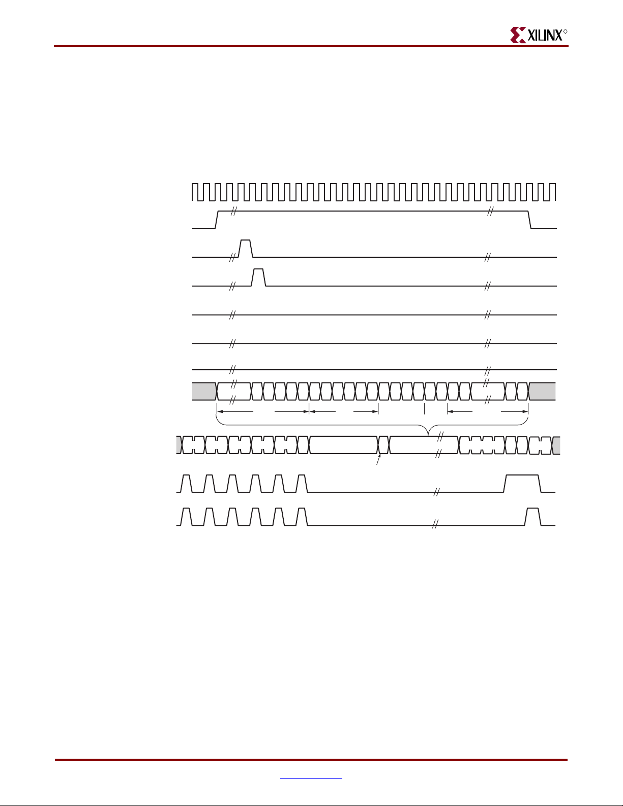
Chapter 3: Client, Host, and MDIO Interfaces
www.BDTIC.com/XILINX
Virtual LAN (VLAN) Tagged Frames
Figure 3-7 shows the transmission of a VLAN tagged frame (if enabled). The handshaking
signals across the interface do not change. However, the VLAN type tag 0x8100 must be
supplied by the client to show the frame as VLAN tagged. The client also supplies the two
bytes of tag control information, V1 and V2, at the appropriate times in the data stream.
More information on the contents of these two bytes can be found in the IEEE Std 802.32002 specification.
CLIENTEMAC#TXCLIENTCLKIN
CLIENTEMAC#TXDVLD
EMAC#CLIENTTXACK
CLIENTEMAC#TXFIRSTBYTE
CLIENTEMAC#TXUNDERRUN
R
EMAC#CLIENTTXCOLLISION
EMAC#CLIENTTXRETRANSMIT
CLIENTEMAC#TXD[7:0]
EMAC#PHYTXD[7:0]
(SGMII or 1000BASE-X
PCS/PMA only)
EMAC#PHYTXCHARISK
(SGMII or 1000BASE-X
PCS/PMA only)
EMAC#PHYCHARDISPMODE
(SGMII or 1000BASE-X
PCS/PMA only)
Maximum Permitted Frame Length and Jumbo Frames
81 00 V1 V2
DA SA DATA
/I1/ /I2/ /I2/ /I2/ /I2/
/S/
tag
PRE
SFD
L/TVLAN
FCS
/T/ /R/
/I1/
ug074_3_09_062105
Figure 3-7: Transmission of a VLAN Tagged Frame
The maximum length of a frame specified in the IEEE Std 802.3-2002 specification is
1518 bytes for non-VLAN tagged frames. VLAN tagged frames can be extended to
1522 bytes. When jumbo frame handling is disabled and the client attempts to transmit a
frame that exceeds the maximum legal length, the Ethernet MAC inserts an error code to
corrupt the current frame and the frame is truncated to the maximum legal length. When
jumbo frame handling is enabled, frames longer than the legal maximum are transmitted
error free.
For more information on enabling and disabling jumbo frame handling, see
“Configuration Registers,” page 74.
44 www.xilinx.com Embedded Tri-Mode Ethernet MAC User Guide
UG074 (v2.2) February 22, 2010
Page 45

R
www.BDTIC.com/XILINX
Frame Collisions (Half-Duplex 10/100 Mb/s Operation Only)
In half-duplex Ethernet operation, collisions occur on the medium. This is how the
arbitration algorithm is fulfilled. When there is a collision, the Ethernet MAC signals to the
client a need to have data re-supplied as follows:
• If there is a collision, the EMAC#CLIENTTXCOLLISION signal is set to 1 by the
Ethernet MAC. If a frame is in progress, the client must abort the transfer and
CLIENTEMAC#TXDVLD is deasserted to 0.
• If the EMAC#CLIENTTXRETRANSMIT signal is 1 in the same clock cycle as the
EMAC#CLIENTTXCOLLISION signal is 1, the client must resubmit the previous
frame to the Ethernet MAC for retransmission; CLIENTEMAC#TXDVLD must be
asserted to the Ethernet MAC within eight clock cycles of the
EMAC#CLIENTTXCOLLISION signal to meet Ethernet timing requirements. This
operation is shown in Figure 3-8.
CLIENTEMAC#TXCLIENTCLKIN
CLIENTEMAC#TXD[7:0]
Client Interface
CLIENTEMAC#TXDVLD
EMAC#CLIENTTXACK
CLIENTEMAC#TXFIRSTBYTE
CLIENTEMAC#TXUNDERRUN
EMAC#CLIENTTXCOLLISION
EMAC#CLIENTTXRETRANSMIT
Figure 3-8: Collision Handling - Frame Retransmission Required
8 Clocks
Maximum
ug074_3_10_101004
Embedded Tri-Mode Ethernet MAC User Guide www.xilinx.com 45
UG074 (v2.2) February 22, 2010
Page 46

Chapter 3: Client, Host, and MDIO Interfaces
www.BDTIC.com/XILINX
• If the EMAC#CLIENTTXRETRANSMIT signal is 0 in the same clock cycle when the
EMAC#CLIENTTXCOLLISION signal is
exceeded the Ethernet specification, and the frame should be dropped by the client.
The client can then make any new frame available to the Ethernet MAC for
transmission without timing restriction. This process is shown in Figure 3-9.
CLIENTEMAC#TXCLIENTCLKIN
CLIENTEMAC#TXD[7:0]
CLIENTEMAC#TXDVLD
EMAC#CLIENTTXACK
CLIENTEMAC#TXFIRSTBYTE
CLIENTEMAC#TXUNDERRUN
EMAC#CLIENTTXCOLLISION
R
1, the number of retries for this frame has
EMAC#CLIENTTXRETRANSMIT
Figure 3-9: Collision Handling - No Frame Retransmission Required
IFG Adjustment
The length of the IFG can be varied in full-duplex mode. If this function is selected (using
a configuration bit in the transmitter control register, see “Configuration Registers,”
page 74), then the Ethernet MAC exerts back pressure to delay the transmission of the next
frame, until the requested number of idle cycles has elapsed. The number of idle cycles is
controlled by the value on the CLIENTEMAC#TXIFGDELAY port at the start-of-frame
transmission. Figure 3-10 shows the Ethernet MAC operating in this mode.
In full-duplex configurations, the minimum IFG is 12 bytes (96 bit times). In half-duplex
configurations, the minimum supported IFG is 18 bytes (144 bit times) when using the MII
physical interface, or 26 bytes (208 bit times) when using the RGMII physical interface.
ug074_3_11_101004
46 www.xilinx.com Embedded Tri-Mode Ethernet MAC User Guide
UG074 (v2.2) February 22, 2010
Page 47

R
www.BDTIC.com/XILINX
CLIENTEMAC#TXCLIENTCLKIN
CLIENTEMAC#TXD[7:0]
CLIENTEMAC#TXDVLD
EMAC#CLIENTTXACK
CLIENTEMAC#TXFIRSTBYTE
DA SA
Client Interface
DA
CLIENTEMAC#TXIFGDELAY
0x0D
IFG ADJUST VALUE
Figure 3-10: IFG Adjustment
Transmit (TX) Client – 16-bit Wide Interface
This optional configuration can only be used when the Ethernet MAC is configured in
1000BASE-X PCS/PMA mode. The frequency of the transmit client clock is half the
frequency of the internal transmit. The 16-bit client interface allows the Ethernet MAC to
run at an internal clock frequency of greater than 125 MHz. The Ethernet MAC can run at
a line rate greater than 1 Gb/s as specified in IEEE Std 802.3. Therefore, this interface
should not be used for Ethernet compliant designs, but it can be useful for backplane
applications.
The PHYEMAC#MIITXCLK is used as the input clock port for the
CLIENTEMAC#TXCLIENTCLKOUT, divided by two, as shown in Figure 3-1, page 38.
Using a DCM with the transmit client clock (EMACCLIENT#TXCLIENTCLKOUT) as an
input, the divide-by-two clock signal is generated. See Figure 4-28, page 139 for more
information.
As in the 8-bit client interface, the PCS engine inserts code characters in the data stream
from CLIENTEMAC#TXD. Tab le 3 -1 describes these code characters, and IEEE Std 802.3,
Clause 36 has further definitions. CLIENTEMAC#TXD[7:0] is transmitted to
EMAC#PHYTXD first. Along with EMAC#PHYTXCHARISK and
EMAC#PHYTXCHARDISPMODE, the MGT encodes the incoming data to the appropriate
8B/10B stream.
Next IFG
ADJUST VALUE
13 Idles Inserted
ug074_3_12_101004
Figure 3-11 shows the timing of a normal outbound frame transfer for the case with an
even number of bytes in the frame.
Embedded Tri-Mode Ethernet MAC User Guide www.xilinx.com 47
UG074 (v2.2) February 22, 2010
Page 48

Chapter 3: Client, Host, and MDIO Interfaces
www.BDTIC.com/XILINX
CLIENTEMAC#TXCLIENTCLKIN
R
(CLIENTEMAC#TXCLIENTCLKIN/2)
PHYEMAC#MIITXCLK
CLIENTEMAC#TXDVLD
CLIENTEMAC#TXDVLDMSW
EMAC#CLIENTTXACK
CLIENTEMAC#TXFIRSTBYTE
CLIENTEMAC#TXUNDERRUN
EMAC#CLIENTTXCOLLISION
EMAC#CLIENTTXRETRANSMIT
CLIENTEMAC#TXD[15:0]
EMAC#PHYTXD[7:0]
(SGMII or 1000BASE-X
PCS/PMA only)
EMAC#PHYTXCHARISK
(SGMII or 1000BASE-X
PCS/PMA only)
EMAC#PHYTXCHARDISPMODE
(SGMII or 1000BASE-X
PCS/PMA only)
DA SA DATA
/I1/ /I2/ /I2/ /I2/ /I2/
/S/
PRE
SFD
Figure 3-11: 16-Bit Transmit (Even Byte Case)
FCS
/I1/
/T/ /R/
ug074_3_13_080705
Figure 3-12 shows the timing of a normal outbound frame transfer for the case with an odd
number of bytes in the frame.
48 www.xilinx.com Embedded Tri-Mode Ethernet MAC User Guide
UG074 (v2.2) February 22, 2010
Page 49

R
www.BDTIC.com/XILINX
CLIENTEMAC#TXCLIENTCLKIN
Client Interface
(CLIENTEMAC#TXCLIENTCLKIN/2)
PHYEMAC#MIITXCLK
CLIENTEMAC#TXDVLD
CLIENTEMAC#TXDVLDMSW
EMAC#CLIENTTXACK
CLIENTEMAC#TXFIRSTBYTE
CLIENTEMAC#TXUNDERRUN
EMAC#CLIENTTXCOLLISION
EMAC#CLIENTTXRETRANSMIT
CLIENTEMAC#TXD[15:0]
EMAC#PHYTXD[7:0]
(SGMII or 1000BASE-X
PCS/PMA only)
EMAC#PHYTXCHARISK
(SGMII or 1000BASE-X
PCS/PMA only)
EMAC#PHYTXCHARDISPMODE
(SGMII or 1000BASE-X
PCS/PMA only)
DA SA DATA
/I1/ /I2/ /I2/ /I2/ /I2/
/S/
PRE
SFD
Figure 3-12: 16-Bit Transmit (Odd Byte Case)
FCS
/R/
/T/ /R/
ug074_3_14_080705
/I1/
As shown in Figure 3-12, CLIENTEMAC#TXDVLDMSW denotes an odd number of bytes
in the frame. In the odd byte case, CLIENTEMAC#TXDVLDMSW is deasserted one clock
cycle earlier than the CLIENTEMAC#TXDVLD signal, after the transmission of the frame.
Otherwise, these data valid signals are the same as shown in the even byte case
(Figure 3-11).
Back-to-Back Transfers
For back-to-back transfers, both the CLIENTEMAC#TXDVLD and
CLIENTEMAC#TXDVLDMSW must be deasserted for one PHYEMAC#MIITXCLK clock
cycle (half the clock frequency of CLIENTEMAC#TXCLIENTCLKIN) after the first frame.
During the following PHYEMAC#MIITXCLK clock cycle, both CLIENTEMAC#TXDLVD
and CLIENTEMAC#TXDVLDMSW must be set High to indicate that the first two bytes of
the destination address of the second frame is ready for transmission on
CLIENTEMAC#TXD[15:0]. In 16-bit mode, this one PHYEMAC#MIITXCLK clock cycle
IFG corresponds to a 2-byte gap (versus a 1-byte gap in 8-bit mode) between frames in the
back-to-back transfer.
Embedded Tri-Mode Ethernet MAC User Guide www.xilinx.com 49
UG074 (v2.2) February 22, 2010
Page 50

Chapter 3: Client, Host, and MDIO Interfaces
www.BDTIC.com/XILINX
Figure 3-13 shows the timing diagram for 16-bit transmit for an even-byte case, and
Figure 3-14 shows the timing diagram for an odd-byte case.
CLIENTEMAC#TXCLIENTCLKIN
R
(CLIENTEMAC#TXCLIENTCLKIN/2)
PHYEMAC#MIITXCLK
CLIENTEMAC#TXD[15:0]
CLIENTEMAC#TXDVLD
CLIENTEMAC#TXDVLDMSW
EMAC#CLIENTTXACK
CLIENTEMAC#TXFIRSTBYTE
CLIENTEMAC#TXUNDERRUN
EMAC#CLIENTTXCOLLISION
EMAC#CLIENTTXRETRANSMIT
Figure 3-13: 16-Bit Transmit Back-to-Back Transfer (Even Byte Case)
D(n-2), D(n-3) D(n), D(n-1) DA1, DA0 DA3, DA2 DA5, DA4
1st Frame IFG 2nd Frame
ug074_3_15_101004
CLIENTEMAC#TXCLIENTCLKIN
PHYEMAC#MIITXCLK
(CLIENTEMAC#TXCLIENTCLKIN/2)
CLIENTEMAC#TXD[15:0]
CLIENTEMAC#TXDVLD
CLIENTEMAC#TXDVLDMSW
EMAC#CLIENTTXACK
CLIENTEMAC#TXFIRSTBYTE
CLIENTEMAC#TXUNDERRUN
EMAC#CLIENTTXCOLLISION
EMAC#CLIENTTXRETRANSMIT
Figure 3-14: 16-Bit Transmit Back-to-Back Transfer (Odd Byte Case)
D(n-1), D(n-2) DA1, DA0 DA3, DA2 DA5, DA4
0xXX, D(n)
1st Frame IFG 2nd Frame
ug074_3_16_101004
50 www.xilinx.com Embedded Tri-Mode Ethernet MAC User Guide
UG074 (v2.2) February 22, 2010
Page 51

R
www.BDTIC.com/XILINX
Receive (RX) Client – 8-bit Wide Interface
In this configuration, EMAC#CLIENTRXD[15:8] and EMAC#CLIENTRXDVLDMSW
signals are left unconnected.
Normal Frame Reception
The timing of a normal inbound frame transfer is shown in Figure 3-15. The client must
accept data at any time; there is no buffering within the Ethernet MAC to allow for receive
client latency. After frame reception begins, data is transferred on consecutive clock cycles
to the receive client until the frame is complete. The Ethernet MAC asserts the
EMAC#CLIENTRXGOODFRAME signal to indicate successful receipt of the frame and
the ability to analyze the frame by the client.
CLIENTEMAC#RXCLIENTCLKIN
EMAC#CLIENTRXD[7:0]
DA SA DATAL/T
EMAC#CLIENTRXDVLD
Client Interface
EMAC#CLIENTRXGOODFRAME
EMAC#CLIENTRXBADFRAME
Frame parameters (destination address, source address, LT, data, and optionally FCS) are
supplied on the data bus as shown in the timing diagram. The abbreviations are the same
as those described in Tab le 3 -1, pa g e 3 9 .
If the LT field has a length interpretation, the inbound frame could be padded to meet the
Ethernet minimum frame size specification. This padding is not passed to the client in the
data payload; an exception is when FCS passing is enabled. See “Client-Supplied FCS
Passing,” page 54.
Therefore, when client-supplied FCS passing is disabled, EMAC#CLIENTRXDVLD = 0
between frames for the duration of the padding field (if present), the FCS field, carrier
extension (if present), the IFG following the frame, and the preamble field of the next
frame. When client-supplied FCS passing is enabled, EMAC#CLIENTRXDVLD = 0
between frames for the duration of carrier extension (if present), the IFG, and the preamble
field of the following frame.
EMAC#CLIENTRXGOODFRAME, EMAC#CLIENTRXBADFRAME Timing
Although the timing diagram in Figure 3-15 shows the EMAC#CLIENTRXGOODFRAME
signal asserted shortly after the last valid data on EMAC#CLIENTRXD[7:0], this is not
always the case. The EMAC#CLIENTRXGOODFRAME or
EMAC#CLIENTRXBADFRAME signals are asserted only after completing all the frame
checks. This is after receipt of the FCS field (and after reception of the carrier extension if
present).
ug074_3_17_051704
Figure 3-15: Normal Frame Reception
Therefore, either EMAC#CLIENTRXGOODFRAME or EMAC#CLIENTRXBADFRAME is
asserted following frame reception at the beginning of the IFG.
Embedded Tri-Mode Ethernet MAC User Guide www.xilinx.com 51
UG074 (v2.2) February 22, 2010
Page 52

Chapter 3: Client, Host, and MDIO Interfaces
www.BDTIC.com/XILINX
SGMII/1000BASE-X PCS/PMA
In SGMII or 1000BASE-X PCS/PMA mode, an entire data stream received from
PHYEMAC#RXD is passed on to EMAC#CLIENTRXD with some latency. This includes
the code group described in Tab le 3- 1. The assertion of EMAC#RXCLIENTDVLD indicates
the position of the first destination address byte all the way to the last byte of the payload.
Figure 3-16 and Figure 3-17 show the timing of a normal inbound frame transfer in SGMII
and 1000BASE-X PCS/PMA mode.
CLIENTEMAC#RXCLIENTCLKIN
PHYEMAC#RXCHARISCOMMA
PHYEMAC#RXCHARISK
/I1/ /I2/ /I2/ /I2/ /I2/ /S/
PHYEMAC#RXD[7:0]
PREAMBLE
DA SA Data
TL
R
EMAC#CLIENTRXD[7:0]
EMAC#RXCLIENTDVLD
EMAC#CLIENTRXGOODFRAME
EMAC#CLIENTRXBADFRAME
EMAC#CLIENTRXSTATS[6:0]
EMAC#CLIENTRXSTATSVLD
CLIENTEMAC#RXCLIENTCLKIN
PHYEMAC#RXCHARISCOMMA
PHYEMAC#RXCHARISK
PHYEMAC#RXD[7:0]
PRE
UG074_3_18_072705
Figure 3-16: Inbound Frame Transfer (Front)
110 20 30 40
FCS /I1/ /R//T/
DATA
EMAC#CLIENTRXD[7:0]
EMAC#RXCLIENTDVLD
EMAC#CLIENTRXGOODFRAME
EMAC#CLIENTRXBADFRAME
EMAC#CLIENTRXSTATS[6:0]
EMAC#CLIENTRXSTATSVLD
PREAMBLE DA
Figure 3-17: Inbound Frame Transfer (Back)
52 www.xilinx.com Embedded Tri-Mode Ethernet MAC User Guide
SA
TL
Data
UG074_3_19_072705
UG074 (v2.2) February 22, 2010
Page 53

R
www.BDTIC.com/XILINX
Frame Reception with Errors
An unsuccessful frame reception (for example, a fragment frame or a frame with an
incorrect FCS) is shown in Figure 3-18. In this case, the EMAC#CLIENTRXBADFRAME
signal is asserted to the client at the end of the frame. The client is responsible for dropping
the data already transferred for this frame.
CLIENTEMAC#RXCLIENTCLKIN
EMAC#CLIENTRXD[7:0]
EMAC#CLIENTRXDVLD
EMAC#CLIENTRXGOODFRAME
EMAC#CLIENTRXBADFRAME
Client Interface
DA SADATAL/T
Figure 3-19 shows the timing of an unsuccessful frame reception in SGMII and
1000BASE-X PCS/PMA modes.
CLIENTEMAC#RXCLIENTCLKIN
PHYEMAC#RXCHARISCOMMA
PHYEMAC#RXCHARISK
PHYEMAC#RXD[7:0]
EMAC#CLIENTRXD[7:0]
EMAC#CLIENTRXDVLD
EMAC#CLIENTRXGOODFRAME
EMAC#CLIENTRXBADFRAME
ug074_3_20_080805
Figure 3-18: Frame Reception with Error
/T/ /R/ /l1/
FCS
/V/
PRE DA SA Data FCS
UG074_3_21_081805
Figure 3-19: Unsuccessful Frame Reception (SGMII and 1000BASE-X PCS/PMA Modes)
The following conditions cause the assertion of EMAC#CLIENTRXBADFRAME:
• Standard Conditions:
• FCS errors occur.
• Packets are shorter than 64 bytes (undersize or fragment frames).
Embedded Tri-Mode Ethernet MAC User Guide www.xilinx.com 53
UG074 (v2.2) February 22, 2010
Page 54

Chapter 3: Client, Host, and MDIO Interfaces
www.BDTIC.com/XILINX
• VLAN frames of length 1519 to 1522 are received when VLAN frames are not
enabled.
• Jumbo frames are received when jumbo frames are not enabled.
•A value of 0x0000 to 0x002D is in the type/length field. In this situation, the
frame should be padded to the minimum length. If not padded to exactly the
minimum frame length, the frame is marked as bad (when length/type checking
is enabled).
•A value of 0x002E to 0x0600 is in the type/length field, but the real length of the
received frame does not match this value (when length/type checking is
enabled).
• Any control frame that is received is not exactly the minimum frame length
(64 bytes).
• PHYEMAC#RXER is asserted at any point during frame reception.
• An error code is received in the 1-Gb frame extension field.
• A valid pause frame, addressed to the Ethernet MAC, is received when flow
control is enabled.
Refer to “Flow Control Block,” page 61 for more information.
• 1000BASE-X/SGMII Specific Conditions:
When in 1000BASE-X or SGMII mode, these errors can also cause a frame to be marked
as bad:
R
• Unrecognized 8B/10B code group received during the packet.
• 8B/10B running disparity errors occurred during the packet.
• Unexpected K characters or sequences appeared in the wrong order/byte
position.
Client-Supplied FCS Passing
Figure 3-20 shows the handling of the case where the Ethernet MAC is configured to pass
the FCS field to the client (see “Configuration Registers,” page 74). In this case, any
padding inserted into the frame to meet Ethernet minimum frame length specifications is
left intact and passed to the client.
Even though the FCS is passed up to the client, it is also verified by the Ethernet MAC, and
EMAC#CLIENTRXBADFRAME is asserted if the FCS check fails.
54 www.xilinx.com Embedded Tri-Mode Ethernet MAC User Guide
UG074 (v2.2) February 22, 2010
Page 55

R
www.BDTIC.com/XILINX
CLIENTEMAC#RXCLIENTCLKIN
EMAC#CLIENTRXD[7:0]
EMAC#CLIENTRXDVLD
EMAC#CLIENTRXGOODFRAME
EMAC#CLIENTRXBADFRAME
Figure 3-20: Frame Reception with In-Band FCS Field
VLAN Tagged Frames
The reception of a VLAN tagged frame (if enabled) is shown in Figure 3-21. The VLAN
frame is passed to the client to identify the frame as VLAN tagged. This is followed by the
tag control information bytes, V1 and V2. More information on the interpretation of these
bytes is described in the IEEE Std 802.3-2002 standard.
Client Interface
DA SA DATAL/T FCS
ug074_3_22_080805
CLIENTEMAC#RXCLIENTCLKIN
EMAC#CLIENTRXD[7:0]
EMAC#CLIENTRXDVLD
EMAC#CLIENTRXGOODFRAME
EMAC#CLIENTRXBADFRAME
Maximum Permitted Frame Length/ Jumbo Frames
The maximum length of a frame specified in the IEEE Std 802.3-2002 standard is 1518 bytes
for non-VLAN tagged frames. VLAN tagged frames can be extended to 1522 bytes. When
jumbo frame handling is disabled and the Ethernet MAC receives a frame exceeding the
maximum legal length, EMAC#CLIENTRXBADFRAME is asserted. When jumbo frame
handling is enabled, frames longer than the legal maximum are received in the same way
as shorter frames.
81 00 V1 V2
DA SA D ATAL/T
VLAN
Tag
Figure 3-21: Reception of a VLAN Tagged Frame
ug074_3_23_080805
For more information on enabling and disabling jumbo frame handling, see
“Configuration Registers,” page 74.
Embedded Tri-Mode Ethernet MAC User Guide www.xilinx.com 55
UG074 (v2.2) February 22, 2010
Page 56

Chapter 3: Client, Host, and MDIO Interfaces
www.BDTIC.com/XILINX
Length/Type Field Error Checks
Length/Type Field Error checking is specified in IEEE Std 802.3. The Length/Type Field
Error checks consist of comparing the value in the Length/Type field with the actual size of
the data field received. This check is only performed when the value in the Length/Type
field is less than 1536 (0x600). This check does not perform any checks on the total length
of the frame. This functionality must be enabled to comply with this specification.
Disabling Length/Type checking is intended only for specific applications, such as when
using over a proprietary backplane.
Enabled
When Length/Type error checking is enabled (see “Receiver Configuration Register (Word
1),” page 75), the following checks are made on frames with a value less than 1536 (0x600)
in the Length/Type field. (If either of these checks fails, EMAC#CLIENTRXBADFRAME is
asserted):
• A value greater than or equal to decimal 46 but less than decimal 1536 (a length
interpretation) in the Length/Type field is checked against the actual data length
received.
• A value less than decimal 46 in the Length/Type field is checked to ensure the data
field is padded to exactly 46 bytes.
R
Furthermore, if padding is indicated (the Length/Type field is less than decimal 46) and
client-supplied FCS passing is disabled, then the length value in the Length/Type field is
used to deassert EMAC#CLIENTRXDVLD after the indicated number of data bytes,
removing the padding bytes from the frame.
Disabled
When the Length/Type error checking is disabled (see “Receiver Configuration Register
(Word 1),” page 75), the Length/Type error checks described above are not performed. A
frame containing only these errors causes EMAC#CLIENTRXGOODFRAME to be
asserted. Disabling this check does not disable total frame length checks. Any frame of less
than 64 total bytes (minimum frame size) or any frame exceeding the maximum frame size
checks (if enabled) will still cause EMAC#CLIENTRXBADFRAME to be asserted. Control
frames will still be marked bad if they are not exactly 64 bytes in total length.
Furthermore, if padding is indicated and client-supplied FCS passing is disabled, then a
length value in the Length/Type field is not used to deassert EMAC#CLIENTRXDVLD.
Instead EMAC#CLIENTRXDVLD is deasserted before the start of the FCS field; in this
way, any padding is not removed from the frame.
Receive (RX) Client – 16-bit Wide Interface
This optional configuration can only be used when the Ethernet MAC is configured in
1000BASE-X PCS/PMA mode. The frequency of the receive client clock is half the
frequency of the internal receive clock. The 16-bit client interface allows the Ethernet MAC
to run at an internal clock frequency of greater than 125 MHz. The interface allows the
Ethernet MAC to run at a line rate greater than 1 Gb/s as specified in IEEE Std 802.3.
Therefore, the interface should not be used for Ethernet compliant applications, but it can
be useful for customer’s backplane applications.
The PHYEMAC#RXCLK is used as the input clock port for the
CLIENTEMAC#RXCLIENTCLKOUT divided by two, as shown in the receive client block
diagram in Figure 3-2, page 39. Using a DCM with the receive client clock,
56 www.xilinx.com Embedded Tri-Mode Ethernet MAC User Guide
UG074 (v2.2) February 22, 2010
Page 57

R
www.BDTIC.com/XILINX
EMACCLIENT#RXCLIENTCLKOUT as an input, the divide-by-two clock signal is
generated. See Figure 4-28, page 139 for more information.
Figure 3-22 shows the timing of a normal inbound frame transfer for the case with an even
number of bytes in the frame.
CLIENTEMAC#RXCLIENTCLKIN
PHYEMAC#RXCLK
(CLIENTEMAC#RXCLIENTCLKIN/2)
EMAC#CLIENTRXD[15:0]
EMAC#CLIENTRXDVLD
EMAC#CLIENTRXDVLDMSW
EMAC#CLIENTRXGOODFRAME
Client Interface
DA SA D ATA
EMAC#CLIENTRXBADFRAME
Figure 3-22: 16-Bit Receive (Even Byte Case)
Figure 3-23 shows the timing of a normal inbound frame transfer for the case with an odd
number of bytes in the frame.
CLIENTEMAC#RXCLIENTCLKIN
PHYEMAC#RXCLK
(CLIENTEMAC#RXCLIENTCLKIN/2)
EMAC#CLIENTRXD[15:0]
EMAC#CLIENTRXDVLD
EMAC#CLIENTRXDVLD MSW
EMAC#CLIENTRXGOODFRAME
EMAC#CLIENTRXBADFRAME
ug074_3_24_082007
DA SA D ATA
ug074_3_25_080805
Figure 3-23: 16-Bit Receive (Odd Byte Case)
As shown in Figure 3-22 and Figure 3-23, EMAC#CLIENTRXDVLDMSW is used to denote
an odd number of bytes in the frame. The data valid signals are shown in the even byte
case (Figure 3-22). In the odd byte case (Figure 3-23), EMAC#CLIENTRXDVLDMSW is
deasserted one clock cycle earlier compared to the EMAC#CLIENTRXDVLD signal, after
the reception of the frame. EMAC#CLIENTRXD[7:0] contains the data in this odd byte
case.
Embedded Tri-Mode Ethernet MAC User Guide www.xilinx.com 57
UG074 (v2.2) February 22, 2010
Page 58

Chapter 3: Client, Host, and MDIO Interfaces
www.BDTIC.com/XILINX
Address Filtering
The address filtering block accepts or rejects frames by examining the destination address
of an incoming frame. This block includes:
• Programmable unicast destination address matching
• Four programmable multicast address matching
• Broadcast address recognition (0xFFFF_FFFF_FFFF)
• Optional pass-through mode with address filter disabled (promiscuous mode)
• Pause control frame address recognition (0x0100_00C2_8001)
The Address Filter (AF) protects the client from extraneous traffic. With this technique, the
hardware matches the Destination Address (DA) field of the Ethernet MAC frame. This
relieves the task from the bus and software.
The AF is programmed in software through the host interface. Typically this includes
unicast and multicast addresses. Pause-frame addresses and broadcast address are
hardwired; they do not need to be programmed. The AF can be enabled and disabled
under software control, using an enable bit in the control register. See “Address Filter
Registers,” page 80 for the control register.
When the function is enabled, Ethernet frames are passed to the client interface only if they
pass the filter. When the AF function is disabled, all incoming RX frames are passed to the
client interface.
R
For system monitoring, the event of a frame failing the filter is signaled. Equally, when a
frame passes the filter, a match is indicated to the client by using the output pins
EMAC#CLIENTRXDVLD and EMAC#CLIENTRXFRAMEDROP together. Ta bl e 3 -2
shows the values of the two signals for possible outcomes of an incoming RX frame when
the AF is enabled. Ta bl e 3 -3 shows the two signal values when the AF is disabled (in
promiscuous mode).
When the AF is enabled, it is impossible to determine if there is an incoming RX frame or
if the AF has rejected incoming RX frames (using only EMAC#CLIENTRXDVLD) because
in both cases, the EMAC#CLIENTRXDVLD is deasserted. See Ta bl e 3- 2. However, using
the EMAC#CLIENTRXFRAMEDROP signal, the nature of an incoming RX frame can be
distinguished for system monitoring.
Table 3-2: EMAC#CLIENTRXDVLD and EMAC#CLIENTRXFRAMEDROP Values When AF is Enabled
EMAC#CLIENTRXDVLD EMAC#CLIENTRXFRAMEDROP Result of an Incoming RX Frame
00No incoming RX frame
01AF rejects RX frame
10AF passes RX frame
11N/A
Table 3-3: EMAC#CLIENTRXDVLD and EMAC#CLIENTRXFRAMEDROP Values When AF is Disabled
EMAC#CLIENTRXDVLD EMAC#CLIENTRXFRAMEDROP Result of an Incoming RX Frame
00No incoming RX frame
01N/A
10AF passes RX frame
11AF rejects RX frame
58 www.xilinx.com Embedded Tri-Mode Ethernet MAC User Guide
UG074 (v2.2) February 22, 2010
Page 59

R
www.BDTIC.com/XILINX
Host/Tie Interface
The host/tie interfaces provide the host, or fabric, access to the control registers for the
address filter.
The tie-off interface allows the unicast address register, pause frame source address, and
address filter promiscuous mode bit to be set directly by the fabric when the FPGA is
configured. In this way, the address filter performs functions with the unicast address
without using the host interface. The TIEEMAC#UNICASTADDR[47:0] and
TIEEMAC#CONFIGVEC[47:0] should both be tied to the unicast address.
TIEEMAC#UNICASTADDR[47:0] initializes unicast address word 0 [31:0] and unicast
address word 1 [15:0] while TIEEMAC#CONFIGVEC[47:0] initializes the pause frame
source address of the receiver configuration register word 0 [31:0] and receiver
configuration register word 1[15:0]. TIEEMAC#CONFIGVEC[64] initializes the
promiscuous mode bit (bit [31] of the address filter mode register). The tie interface does
not initialize the four multicast address register values.
When the host interface is used, all the address filter registers are accessible by software,
using either the DCR bus or the generic host bus. The tie interface initialization values to
the registers can be overridden by the software through the host interface. Also, the four
multicast address registers are programmed through the host interface.
Client Interface
Client RX Data/Control Interface
The AF generates the EMAC#CLIENTRXFRAMEDROP signal to inform the client that the
destination MAC address of an incoming receive Ethernet frame does not match with any
of the acceptable addresses stored in the AF. This control signal is asserted regardless of
whether the AF is enabled or disabled (promiscuous mode).
Figure 3-24 shows the timing diagram when a frame matches a valid location in the AF
(8-bit mode). The address filter is disabled in this timing diagram.
CLIENTEMAC#RXCLIENTCLKIN
EMAC#CLIENTRXDVLD
EMAC#CLIENTRXD[7:0]
EMAC#CLIENTRXGOODFRAME
EMAC#CLIENTRXFRAMEDROP
Previous Frame
Dropped
nn–1n–2 n+1 n+2 n+3 n+4 n+5 n+6 n+7
DA SA
Current Frame
Passed
ug074_3_26_080805
Figure 3-24: Frame Matching Timing Diagram (8-Bit Mode)
Embedded Tri-Mode Ethernet MAC User Guide www.xilinx.com 59
UG074 (v2.2) February 22, 2010
Page 60

Chapter 3: Client, Host, and MDIO Interfaces
www.BDTIC.com/XILINX
Figure 3-25 shows the timing diagram when a frame matches a valid location in the AF
(16-bit mode). The address filter is disabled in this timing diagram.
CLIENTEMAC#RXCLIENTCLKIN
PHYEMAC#RXCLK
EMAC#CLIENTRXDVLD
EMAC#CLIENTRXDVLDMSW
R
nn–4n–5 n–2 n–1n–3 n+1 n+2 n+3 n+4 n+5 n+6
EMAC#CLIENTRXD[15:0]
EMAC#CLIENTRXGOODFRAME
EMAC#CLIENTRXFRAMEDROP
Figure 3-25: Frame Matching Timing Diagram (16-Bit Mode)
Figure 3-26 shows the timing diagram when a frame fails to match a valid location in the
AF (8-bit mode) and the frame drop signal is generated. The address filter is disabled in
this timing diagram.
CLIENTEMAC#RXCLIENTCLKIN
EMAC#CLIENTRXDVLD
EMAC#CLIENTRXD[7:0]
EMAC#CLIENTRXGOODFRAME
Previous Frame
Dropped
DA1, DA0 DA3, DA2 DA5, DA4
DA
Current Frame
Passed
nn–1n–2 n+1 n+2 n+3 n+4 n+5 n+6 n+7
DA SA
ug074_3_27_080805
EMAC#CLIENTRXFRAMEDROP
Previous Frame
Passed
Figure 3-26: Frame Matching Failed Timing Diagram (8-Bit Mode)
60 www.xilinx.com Embedded Tri-Mode Ethernet MAC User Guide
Current Frame
Dropped
ug074_3_28_080805
UG074 (v2.2) February 22, 2010
Page 61
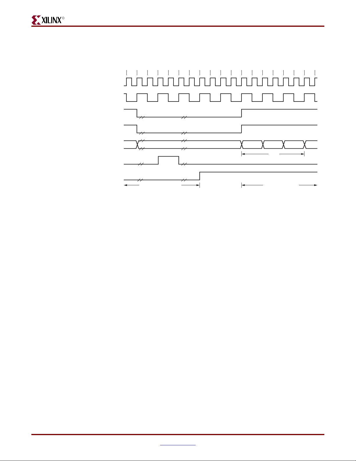
R
www.BDTIC.com/XILINX
Figure 3-27 shows the timing diagram when a frame fails to match a valid location in the
AF (16-bit mode) and the frame drop signal is generated. The address filter is disabled in
this timing diagram.
CLIENTEMAC#RXCLIENTCLKIN
PHYEMAC#RXCLK
EMAC#CLIENTRXDVLD
EMAC#CLIENTRXDVLDMSW
Client Interface
nn–4n–5 n–2 n–1n–3 n+1 n+2 n+3 n+4 n+5 n+6
EMAC#CLIENTRXD[15:0]
EMAC#CLIENTRXGOODFRAME
EMAC#CLIENTRXFRAMEDROP
Figure 3-27: Frame Matching Failed Timing Diagram (16-Bit Mode)
Flow Control Block
The flow control block is designed to Clause 31 of the IEEE Std 802.3-2002 standard. The
Ethernet MAC can be configured to send pause frames to act upon the pause frame’s
reception during full-duplex operation. These two behaviors can be configured
asymmetrically (see “Configuration Registers,” page 74).
Requirement for Flow Control
Figure 3-28 illustrates the requirement for flow control. The Ethernet MAC on the right
side of the figure has a reference clock slightly faster than the nominal 125 MHz. The
Ethernet MAC on the left side of the figure has a reference clock slightly slower than the
nominal 125 MHz. This results in the Ethernet MAC on the left side of the figure not being
able to match the full line rate of the Ethernet MAC on the right side (due to clock
tolerances). The left Ethernet MAC is illustrated as performing a loopback
implementation; this results in the FIFO filling up over time. Without flow control, this
FIFO eventually fills and overflows, resulting in the corruption or loss of Ethernet frames.
Previous Frame
Passed
DA1, DA0 DA3, DA2 DA5, DA4
DA
Current Frame
Dropped
ug074_3_29_080805
Embedded Tri-Mode Ethernet MAC User Guide www.xilinx.com 61
UG074 (v2.2) February 22, 2010
Page 62

Chapter 3: Client, Host, and MDIO Interfaces
www.BDTIC.com/XILINX
R
Client Logic
Application
FIFO
MAC
Tx
Rx
Figure 3-28: Requirement for Flow Control
125 MHz –100 ppm
125 MHz +100 ppm
MAC
Rx
Tx
ug074_3_30_080705
Flow Control Basics
An Ethernet MAC transmits a pause control frame for the link partner to cease
transmission for a defined period of time. For example, the left Ethernet MAC of
Figure 3-28 initiates a pause request when the client FIFO (illustrated) reaches a nearly full
state.
An Ethernet MAC responds to received pause control frames by ceasing transmission of
frames for the period of time defined in the received pause control frame. For example, the
right Ethernet MAC of Figure 3-28 ceases transmission after receiving the pause control
frame transmitted by the left Ethernet MAC. In a well-designed system, the right Ethernet
MAC ceases transmission before the client FIFO of the left Ethernet MAC is overflowed.
This provides time to empty the FIFO to a safe level before normal operation resumes. It
also safe guards the system against FIFO overflow conditions and frame loss.
62 www.xilinx.com Embedded Tri-Mode Ethernet MAC User Guide
UG074 (v2.2) February 22, 2010
Page 63

R
www.BDTIC.com/XILINX
Transmitting a PAUSE Control Frame
The client initiates a flow control frame by asserting CLIENTEMAC#PAUSEREQ, when
the pause value is on the CLIENTEMAC#PAUSEVAL[15:0] bus. These signals are
synchronous to CLIENTEMAC#TXCLIENTCLKIN. The timing is shown in Figure 3-29.
CLIENTEMAC#TXCLIENTCLKIN
CLIENTEMAC#PAUSEREQ
CLIENTEMAC#PAUSEVAL[15:0]
Figure 3-29: Pause Request Timing
When the Ethernet MAC is configured to support transmit flow control, a PAUSE control
frame is transmitted on the link. When CLIENTEMAC#PAUSEREQ is asserted, the PAUSE
parameter is set to the CLIENTEMAC#PAUSEVAL[15:0] value. This does not disrupt any
frame transmission in progress, but it takes priority over any pending frame transmission.
The PAUSE control frame is transmitted even if the transmitter is in a paused state. An
example of a PAUSE frame (not drawn to scale) is shown in Figure 3-30.
Client Interface
ug074_3_31_080805
64-Byte Data Field
Pause Destination
Address
01-80-C2-00-00-01
Source
Address
MAC
Control
Ty pe
0x8808
MAC
Control
OPCODE
0x0001
Pause
Time
46-Byte Data Field
Figure 3-30: Pause Frame Example
The pause destination address can be configured using the “Configuration Registers”. The
pause_time in the PAUSE frame is the value from the CLIENTEMAC#PAUSEVAL[15:0].
Receiving a PAUSE Control Frame
When an error-free frame is received by the Ethernet MAC, it examines the following
information:
• The destination address field is matched against the Ethernet MAC control multicast
address and the configured source address for the Ethernet MAC (see “Configuration
Registers,” page 74).
• The LT field is matched against the Ethernet MAC control type code.
• If the second match is true, the OPCODE field contents are matched against the
Ethernet MAC control OPCODE.
FCS
ug074_3_32_080805
If any match is false or the Ethernet MAC flow control logic for the receiver is disabled, the
frame is ignored by the flow control logic and passed up to the client.
Embedded Tri-Mode Ethernet MAC User Guide www.xilinx.com 63
UG074 (v2.2) February 22, 2010
Page 64

Chapter 3: Client, Host, and MDIO Interfaces
www.BDTIC.com/XILINX
If the frame passes all of the previous checks, is of minimum legal size, and the Ethernet
MAC flow control logic for the receiver is enabled, then the pause value parameter in the
frame is used to inhibit transmitter operation for a time defined in the IEEE Std 802.3-2002
specification. This inhibit is implemented using the same back pressure scheme shown in
Figure 3-6. Because the received pause frame is completed, it is passed to the client with
EMAC#CLIENTRXBADFRAME asserted, indicating to the client that the frame should be
dropped.
If the second match is true and the frame is not 64 bytes in length, the reception of any
frame is considered to be an invalid control frame. This frame is ignored by the flow
control logic and passed to the client with EMAC#CLIENTRXBADFRAME asserted.
EMAC#CLIENTRXBADFRAME will be asserted even if flow control is not enabled.
Flow Control Implementation Example
In the system illustrated in Figure 3-28, the Ethernet MAC on the left side of the figure
cannot match the full line rate of the right Ethernet MAC due to clock tolerances. Over
time, the FIFO fills and overflows.
This example implements a flow control method to reduce, over a long time period, the full
line rate of the right Ethernet MAC to less than the full line rate capability of the left
Ethernet MAC.
R
Method
1. Choose a FIFO with a nearly full occupancy threshold. A 7/8 occupancy is used in this
description, but the choice of threshold is implementation specific. When the
occupancy of the FIFO exceeds this occupancy, initiate a single pause control frame
with 0xFFFF used as the pause_quantum duration (0xFFFF is placed on
pause_val[15:0]). This is the maximum pause duration and causes the right Ethernet
MAC to cease transmission and the FIFO of the left Ethernet MAC to start emptying.
2. Choose a second FIFO with an occupancy threshold of 3/4 (the choice of threshold is
implementation specific). When the occupancy of the FIFO falls below this occupancy,
initiate a second pause control frame with 0x0000 used as the pause_quantum duration
(0x0000 is placed on pause_val[15:0]). This indicates a zero pause duration, and upon
receiving this pause control frame, the right Ethernet MAC immediately resumes
transmission (i.e., there is no wait for the original requested pause duration to expire).
This PAUSE control frame can, therefore, be considered a “pause cancel” command.
64 www.xilinx.com Embedded Tri-Mode Ethernet MAC User Guide
UG074 (v2.2) February 22, 2010
Page 65

R
www.BDTIC.com/XILINX
Client Interface
Operation
Figure 3-31 illustrates the FIFO occupancy over time.
Full
A
7/8
3/4
FIFO Occupancy
B
5/8
1/2
Figure 3-31: Flow Control Implementation Triggered from FIFO Occupancy
1. The average FIFO occupancy of the left Ethernet MAC gradually increases over time
due to the clock tolerances. At point A, the occupancy has reached the threshold of 7/8
occupancy, triggering the maximum duration pause control frame request.
2. Upon receiving the pause control frame, the right Ethernet MAC ceases transmission.
3. After the right Ethernet MAC ceases transmission, the occupancy of the FIFO attached
to the left Ethernet MAC rapidly empties. The occupancy falls to the second threshold
of 3/4 occupancy at point B, triggering the zero duration pause control frame request
(the pause cancel command).
4. Upon receiving this second pause control frame, the right hand Ethernet MAC
resumes transmission.
5. Normal operation resumes, and the FIFO occupancy again gradually increases over
time. At point C, the flow control cycle repeats.
C
Time
ug074_3_33a_052005
Statistics Vector
Transmitter Statistics Vector
TX_STATISTICS_VECTOR contains the statistics for the frame transmitted. The vector is
driven synchronously by the transmitter clock, CLIENTEMAC#TXCLIENTCLKIN,
following frame transmission. The bit field definition for the transmitter statistics vector is
defined in Tab le 3- 4.
Embedded Tri-Mode Ethernet MAC User Guide www.xilinx.com 65
UG074 (v2.2) February 22, 2010
Page 66

Chapter 3: Client, Host, and MDIO Interfaces
www.BDTIC.com/XILINX
The TX_STATISTICS_VECTOR is a 32-bit wide vector and is internal in the transmit
engine. This vector is muxed out to a one-bit signal, EMAC#CLIENTTXSTATS, as shown in
Figure 3-32.
CLIENTEMAC#TXCLIENTCLKIN
R
TX_STAT ISTICS_VALID
(internal signal)
TX_STAT ISTICS_VECTOR[31:0]
(internal signal)
EMAC#CLIENTTXSTAT SVLD
EMAC#CLIENTTXSTAT S
The block diagram for the transmitter statistics mux in the Ethernet MAC is shown in
Figure 3-33.
012345
Figure 3-32: Transmitter Statistics Mux Timing
Ethernet MAC
TX_STAT ISTICS_VECTOR[31:0]
(Internal Signal)
[31:0]
28 29 30 31
UG074_03_34_080805
TX_STAT ISTICS_VALID
(Internal Signal)
CLIENTEMAC#TXCLIENTCLKIN
EMAC#CLIENTTXSTAT SBYTEVLD
EMAC#CLIENTTXSTAT S
CLIENTEMAC#TXCLIENTCLKIN
RESET
TXSTAT SVEC[31:0] TXSTATSVLD
CLIENTEMAC#TXCLIENTCLKIN
TXSTAT SMUX
Ethernet MAC Block
FPGA Fabric
EMAC#CLIENTTXSTAT SVLD
TXSTAT SDEMUX
User Defined
Statistics Processing Block
ug074_3_35_080805
Figure 3-33: Transmitter Statistics Mux Block Diagram
All bit fields in EMAC#CLIENTTXSTATS are only valid when the
EMAC#CLIENTTXSTATSVLD is asserted as illustrated in Figure 3-34.
EMAC#CLIENTTXSTATSBYTEVLD is asserted if an Ethernet MAC frame byte (DA to FCS
inclusive) is being transmitted. The signal is valid on every
CLIENTEMAC#TXCLIENTCLKIN cycle.
66 www.xilinx.com Embedded Tri-Mode Ethernet MAC User Guide
UG074 (v2.2) February 22, 2010
Page 67

R
www.BDTIC.com/XILINX
TX_STATISTICS_VECTOR (bits 28 down to 20 inclusive) are only for half-duplex mode.
When operating in full-duplex mode these bits are set to a logic 0.
CLIENTEMAC#TXCLIENTCLKIN
CLIENTEMAC#TXD[7:0]
CLIENTEMAC#TXDVLD
EMAC#CLIENTTXACK
CLIENTEMAC#TXFIRSTBYTE
EMAC#CLIENTTXSTAT SBYTEVLD
EMAC#CLIENTTXSTAT SVLD
Client Interface
DA SA DATA L/T
EMAC#CLIENTTXSTAT S
Figure 3-34: Transmitter Statistics Vector Timing
Table 3-4: Bit Definitions for the Transmitter Statistics Vector
TX_STATISTICS_VECTOR Name Description
Asserted if the previous frame was a pause frame
31 PAUSE_FRAME_TRANSMITTED
30 Reserved Undefined.
29 Reserved Returns a logic 0.
[28:25] TX_ATTEMPTS[3:0]
24 Reserved Returns a logic 0.
23 EXCESSIVE_COLLISION
22 LATE_COLLISION
initiated by the Ethernet MAC in response to
asserting CLIENTEMAC#PAUSEREQ.
The number of attempts made to transmit the
previous frame. A 4-bit number where 0x0 = one
attempt; 0x
describes 16 attempts.
Asserted if a collision is detected on each of the
last 16 attempts to transmit the previous frame.
Asserted if a late collision occurred during frame
transmission.
1 = two attempts, up to 0xF which
0 1 31
ug074_3_36_080805
21 EXCESSIVE_DEFERRAL
Embedded Tri-Mode Ethernet MAC User Guide www.xilinx.com 67
UG074 (v2.2) February 22, 2010
Asserted if the previous frame was deferred for
an excessive amount of time as defined by the
maxDeferTime constant in the IEEE Std 802.32002 specification.
Page 68

Chapter 3: Client, Host, and MDIO Interfaces
www.BDTIC.com/XILINX
Table 3-4: Bit Definitions for the Transmitter Statistics Vector (Cont’d)
TX_STATISTICS_VECTOR Name Description
R
20 TX_DEFERRED
19 VLAN_FRAME
[18:5] FRAME_LENGTH_COUNT
4 CONTROL_FRAME
3 UNDERRUN_FRAME
2MULTICAST_FRAME
1 BROADCAST_FRAME
0 SUCCESSFUL_FRAME
Notes:
1. Bits [28:20] of TX_STATISTICS_VECTOR are valid for half-duplex mode only.
Asserted if transmission of the frame was
deferred.
Asserted if the previous frame contains a VLAN
identifier in the LT field when transmitter VLAN
operation is enabled.
The length of the previous frame in number of
bytes. The count sticks at 16383 for jumbo frames
larger than this value. Stops at 16383.
Asserted if the previous frame has the special
Ethernet MAC control type code
88-08 in the LT field.
Asserted if the previous frame contains an
underrun error.
Asserted if the previous frame contains a
multicast address in the destination address field.
Asserted if the previous frame contains a
broadcast address in the destination address
field.
Asserted if the previous frame is transmitted
without error.
Receiver Statistics Vector
RX_STATISTICS_VECTOR contains the statistics for the frame received. The vector is
driven synchronously by the receiver clock, CLIENTEMAC#RXCLIENTCLKIN, following
frame reception. The bit field definition for the receiver statistics vector is defined in
Tab le 3 -5 .
The RX_STATISTICS_VECTOR is a 27-bit wide vector, and is internal in the receive engine.
This vector is muxed out to a seven-bit wide signal EMAC#CLIENTRXSTATS[6:0] as
shown in Figure 3-35.
CLIENTEMAC#RXCLIENTCLKIN
RX_STAT ISTICS_VALID
(internal signal)
RX_STAT ISTICS_VECTOR[26:0]
(internal signal)
EMAC#CLIENTRXSTAT SVLD
EMAC#CLIENTRXSTAT S[6:0]
[6:0] [13:7] [20:14] [26:21]
Figure 3-35: Receiver Statistics MUX Timing
ug074_3_37_080805
68 www.xilinx.com Embedded Tri-Mode Ethernet MAC User Guide
UG074 (v2.2) February 22, 2010
Page 69

R
www.BDTIC.com/XILINX
Client Interface
The block diagram for the receiver statistics MUX in the Ethernet MAC is shown in
Figure 3-36.
Ethernet MAC
RX_STAT ISTICS_VECTOR[26:0]
CLIENTEMAC#RXCLIENTCLKIN
EMAC#CLIENTRXSTAT SBYTEVLD
EMAC#CLIENTRXSTAT S[6:0]
CLIENTEMAC#RXCLIENTCLKIN
CLIENTEMAC#RXCLIENTCLKIN
(Internal Signal)
[26:0]
RXSTAT SMUX
RXSTAT SDEMUX
RESET
RXSTAT SVEC[26:0] RXSTATSVLD
User Defined
Statistics Processing Block
RX_STAT ISTICS_VALID
(Internal Signal)
Ethernet MAC Block
#CLIENTRXSTAT SVLD
EMAC
FPGA Fabric
Figure 3-36: Receiver Statistics MUX Block Diagram
Embedded Tri-Mode Ethernet MAC User Guide www.xilinx.com 69
UG074 (v2.2) February 22, 2010
ug074_3_38_080805
Page 70
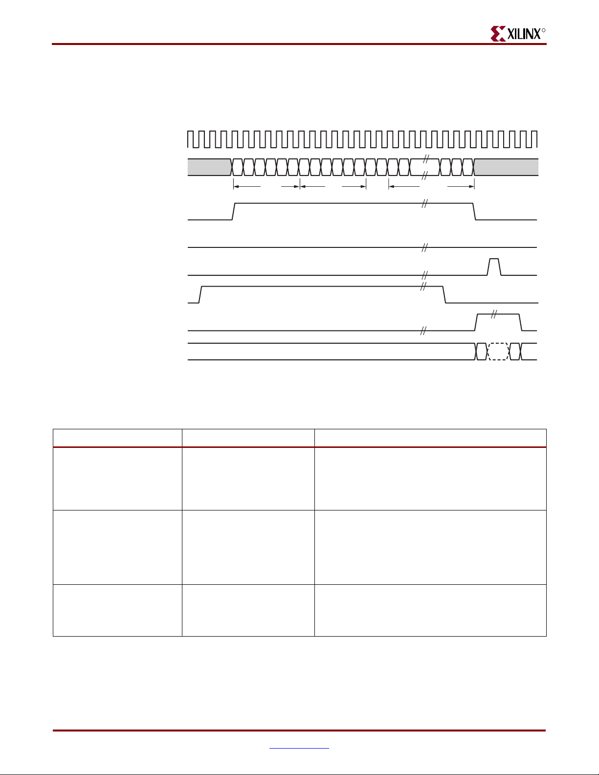
Chapter 3: Client, Host, and MDIO Interfaces
www.BDTIC.com/XILINX
All bit fields for the EMAC#CLIENTRXSTATS[6:0] are valid only when the
EMAC#CLIENTRXSTATSVLD is asserted as illustrated in Figure 3-37.
EMAC#CLIENTRXSTATSBYTEVLD is asserted if an Ethernet MAC frame byte (DA to
FCS inclusive) is received. This is valid on every CLIENTEMAC#RXCLIENTCLKIN cycle.
CLIENTEMAC#RXCLIENTCLKIN
EMAC#CLIENTRXD[7:0]
EMAC#CLIENTRXDVLD
EMAC#CLIENTRXDVLDMSW
EMAC#CLIENTRXGOODFRAME
EMAC#CLIENTRXSTATSBYTEVLD
R
DA SA DATAL/T
EMAC#CLIENTRXSTATSVLD
EMAC#CLIENTRXSTATS[6:0]
Figure 3-37: Receiver Statistics Vector Timing
Table 3-5: Bit Definitions for the Receiver Statistics Vector
RX_STATISTICS_VECTOR Name Description
Used in 10/100 MII mode. If an odd number of nibbles
is received, the last nibble is ignored. If the frame
26 ALIGNMENT_ERROR
25 Length/Type Out of Range
24 BAD_OPCODE
without this nibble has an incorrect FCS, this bit is
asserted. If the frame has a valid FCS, this bit is not
asserted.
Asserted if the LT field contains a length value that
does not match the number of Ethernet MAC client
data bytes received. Also asserted High if the LT field
indicates that the frame contains padding but the
number of Ethernet MAC client data bytes received is
not equal to 46 bytes (minimum frame size).
Asserted if the previous frame is error free, contains the
special control frame identifier in the LT field, but
contains an OPCODE unsupported by the Ethernet
MAC (any OPCODE other than PAUSE).
[6:0] [26:21]
ug074_3_39_010906
70 www.xilinx.com Embedded Tri-Mode Ethernet MAC User Guide
UG074 (v2.2) February 22, 2010
Page 71

R
www.BDTIC.com/XILINX
Table 3-5: Bit Definitions for the Receiver Statistics Vector (Cont’d)
RX_STATISTICS_VECTOR Name Description
Asserted if the previous frame is error-free. Contains
the special control frame identifier in the LT field.
Contains a destination address matching either the
23 FLOW_CONTROL_FRAME
22 Reserved. Undefined.
21 VLAN_FRAME
20 OUT_OF_BOUNDS
Ethernet MAC control multicast address or the
configured source address of the Ethernet MAC.
Contains the supported PAUSE OPCODE and is acted
upon by the Ethernet MAC.
Asserted if the previous frame contains a VLAN
identifier in the LT field when receiver VLAN
operation is enabled.
Asserted if the previous frame exceeded the specified
IEEE Std 802.3-2002 maximum legal length (see
“Maximum Permitted Frame Length/ Jumbo Frames,”
page 55). This is only valid if jumbo frames are
disabled.
Client Interface
19 CONTROL_FRAME
[18:5] FRAME_LENGTH_COUNT
4MULTICAST_FRAME
3 BROADCAST_FRAME
2 FCS_ERROR
1BAD_FRAME
0GOOD_FRAME
Notes:
1. If the length/type field error checks are disabled, then a frame containing this type of error is marked as a GOOD_FRAME,
providing no additional errors were detected.
(1)
(1)
Asserted if the previous frame contains the special
control frame identifier in the LT field.
The length of the previous frame in number of bytes.
The count sticks at 16383 for any jumbo frames larger
than this value.
Asserted if the previous frame contains a multicast
address in the destination address field.
Asserted if the previous frame contained the broadcast
address in the destination address field.
Asserted if the previous frame received has an
incorrect FCS value or the Ethernet MAC detects error
codes during frame reception.
Asserted if the previous frame received contains errors.
Asserted if the previous frame received is error-free.
Statistics Registers/Counters
The Ethernet MAC does not collect statistics on the success and failure of various
operations. A custom statistics counter can be implemented in the FPGA fabric to collect
the statistics. A parameterizable Ethernet statistics core is available from the LogiCORE™
libraries. For more information, see:
http://www.xilinx.com/xlnx/xebiz/designResources/ip_product_details.jsp?sGlobalNavPick=PR
ODUCTS&sSecondaryNavPick=Intellectual+Property&key=ETHERNET_STATS.
When the PowerPC 405 processor is used as a host processor, it can access the statistics
counter registers in the FPGA fabric through the DCR bridge in the host interface. “Inter-
facing to an FPGA Fabric-Based Statistics Block” in Chapter 6 describes the access method.
Embedded Tri-Mode Ethernet MAC User Guide www.xilinx.com 71
UG074 (v2.2) February 22, 2010
Page 72

Chapter 3: Client, Host, and MDIO Interfaces
www.BDTIC.com/XILINX
Host Interface
To access the Ethernet MAC registers through the host interface, the user must set
TIEEMACCONFIGURE[67] = 1. The host interface allows the user to:
• Program the configuration registers in the Ethernet MAC
• Read the accumulated statistics from the statistics unit implemented in the fabric
(optional)
• Access the configuration registers and multicast address table register in the address
filtering unit
• Access the Management Data I/O (MDIO) registers of the physical components
attached to the Ethernet MACs
The two Ethernet MACs share a single host interface. The host interface brings the Ethernet
MAC host bus from the Ethernet MAC out to the fabric. The host interface unit also
contains a DCR bus bridge. This allows the user to access the Ethernet MAC registers
through the DCR bus. Figure 3-38 shows the internal structure of the host interface. The
EMAC1 signal is provided by the HOSTEMAC1SEL input signal when using the generic
host bus or generated by the DCR bridge when using the DCR bus.
The DCREMACENABLE signal is used to select either the generic host bus or the DCR
bus. When this signal is asserted, the host interface uses the DCR bus.
R
DCRHOSTDONEIR
DCREMACENABLE
Virtex- 4 FPGA
DCR Bus
PPC405
Processor Block
Generic Host Bus
DCR
Bridge
Host Interface
Ethernet MAC Block
10
EMAC1
10
EMAC1
EMAC0
ug074_3_40_080805
Figure 3-38: Host Interface
72 www.xilinx.com Embedded Tri-Mode Ethernet MAC User Guide
UG074 (v2.2) February 22, 2010
Page 73

R
www.BDTIC.com/XILINX
HOSTOPCODE[1:0]
HOSTREQ
HOSTWRDATA[31:0]
HOSTRDDATA[31:0]
HOSTMIIMRDY
HOSTCLK
HOSTMIIMSEL
HOSTADDR[9:0]
HOSTEMAC1SEL
DCREMACENABLE
DCRHOSTDONEIR
Figure 3-39 shows the block diagram of the host interface.
MIIMSEL0
REQ0
OPCODE0
ADDR0
WRD0
MIIMRDY0
DCR Bus
(Connected internally
to PowerPC)
Host Interface
RDD0
(All internal signals)
MIIMSEL1
REQ1
OPCODE1
ADDR1
WRD1
MIIMRDY1
RDD1
Host Interface
EMAC0
EMAC1
Ethernet MAC Block
FPGA Fabric
ug074_3_41_080805
Figure 3-39: Ethernet MAC Host Interface Block Diagram
Generic Host Bus
When the generic host bus is used, the HOSTEMAC1SEL signal selects between the host
access of EMAC0 or EMAC1. When HOSTEMAC1SEL is asserted, the host accesses
EMAC1. If only one Ethernet MAC is used, this signal can be tied-off to use either one of
the Ethernet MACs.
To use the DCR bus for the host interface, the DCREMACENABLE signal is asserted.
Because the DCREMACENABLE signal is input from the fabric, it can be tied-off to select
between the DCR bus or the generic host bus during the FPGA power-up configuration.
When using the PowerPC processor and its DCR bus interface to control the Ethernet MAC
registers, either connect the EMAC DCREMACENABLE port to the PPC405
DCREMACENABLER port or assert the DCREMACENABLE input to the EMAC.
The PowerPC processor serves as host processor when a DCR bus is used. Interrupt
request is one of the methods used by the PowerPC processor to determine when the host
interface completes a DCR host access command.
The interrupt request DCRHOSTDONEIR signal is only active when the DCR bus is used,
and the host interface register IRENABLE is programmed to enable interrupt. This signal is
active High and level sensitive. When a host access through the DCR bus is completed, the
DCRHOSTDONEIR signal is asserted. The host needs to service the interrupt request and
clear the host interface register (IRSTATUS) to deassert this signal. See “Using the DCR Bus
as the Host Bus,” page 83 for a description of the DCR.
Access to the management interface depends on the type of transaction. Ta bl e 3- 6 shows
the access method required for each transaction type.
Embedded Tri-Mode Ethernet MAC User Guide www.xilinx.com 73
UG074 (v2.2) February 22, 2010
Page 74

Chapter 3: Client, Host, and MDIO Interfaces
www.BDTIC.com/XILINX
Table 3-6: Management Interface Transaction Types
Transaction HOSTMIIMSEL HOSTADDR[9]
Configuration/Address Filter 01
MDIO access 1X
Host Clock Frequency
The host clock (HOSTCLK) is used to derive the MDIO clock, MDC, and is subject to the
same frequency restrictions. See the Virtex-4 FPGA Data Sheet
parameters.
Configuration Registers
The Ethernet MAC has seven configuration registers. These registers are accessed through
the host interface and can be written to at any time. Both the receiver and transmitter logic
only respond to configuration changes during IFGs. The configurable resets are the only
exception, because the reset is immediate.
Configuration of the Ethernet MAC is performed through a register bank accessed through
the Host interface. Any time an address shown in Tab le 3- 7 is accessed, a 32-bit read or
write is performed from the same configuration word, with the exception of the read-only
Ethernet MAC mode configuration register and the RGMII/SGMII configuration register.
Only the speed selection is both readable and writable in the Ethernet MAC mode
configuration register.
Table 3-7: Configuration Registers
R
for the HOSTCLK frequency
{HOSTEMAC1SEL, HOST_ADDR[9:0]} Register Description
0x200 Receiver Configuration (Word 0)
0x240 Receiver Configuration (Word 1)
0x280 Transmitter Configuration
0x2C0 Flow Control Configuration
0x300 Ethernet MAC Mode Configuration
0x320 RGMII/SGMII Configuration
0x340 Management Configuration
Notes:
1. HOSTEMAC1SEL acts as bit 10 of HOSTADDR.
The configuration registers and the contents of the registers are shown in Ta bl e 3 -8 through
Tab le 3 -1 4.
74 www.xilinx.com Embedded Tri-Mode Ethernet MAC User Guide
UG074 (v2.2) February 22, 2010
Page 75

R
www.BDTIC.com/XILINX
Table 3-8: Receiver Configuration Register (Word 0)
Host Interface
MSB
31 30 29 28 27 26 25 24 23 22 21 20 19 18 17 16 15 14 13 12 11 10 9 8 7 6 5 4 3 2 1 0
0x200 PAUSE_FRAME_ADDRESS[31:0]
Bit Description Default Value R/W
Pause Frame Ethernet MAC Address [31:0]. This address is used
to match the Ethernet MAC against the destination address of
[31:0]
any incoming flow control frames. It is also used by the flow
control block as the source address for any outbound flow
TIEEMAC#CONFIGVEC[31:0] R/W
control frames.
Tie to the same value as TIEEMAC#UNICASTADDR[31:0].
FCS
RX
VLAN
HD
RESERVED PAUSE_FRAME_ADDRESS[47:32]
LT_ DI S
Table 3-9: Receiver Configuration Register (Word 1)
MSB
31 30 29 28 27 26 25 24 23 22 21 20 19 18 17 16 15 14 13 12 11 10 9 8 7 6 5 4 3 2 1 0
0x240
RST
JUM
Bit Description Default Value R/W
[15:0]
Pause frame Ethernet MAC Address [47:32]. Tie to the same
value as TIEEMAC#UNICASTADDR[47:32].
TIEEMAC#CONFIGVEC[47:32] R/W
LSB
LSB
[24:16] Reserved. –
[25]
Length/Type Check disable. When this bit is 1, it disables the
comparison of the L/T field with the size of the data.
TIEEMAC#CONFIGVEC[63] R/W
Half-duplex mode: When this bit is 1, the receiver operates in
[26]
half-duplex mode. When the bit is 0, the receiver operates in full-
TIEEMAC#CONFIGVEC[48] R/W
duplex mode.
VLAN enable: When this bit is 1, the receiver accepts VLAN
[27]
tagged frames. The maximum payload length increases by four
TIEEMAC#CONFIGVEC[49] R/W
bytes.
Receive enable: When this bit is 1, the receiver block is enabled
[28]
to operate. When the bit is 0, the receiver ignores activity on the
TIEEMAC#CONFIGVEC[50] R/W
physical interface receive port.
In-band FCS enable: When this bit is 1, the receiver passes the
[29]
FCS field up to the client. When this bit is 0, the FCS field is not
passed to the client. In either case, the FCS is verified on the
TIEEMAC#CONFIGVEC[51] R/W
frame.
Jumbo frame enable: When this bit is 1, the Ethernet MAC
[30]
receiver accepts frames over the maximum length specified in
IEEE Std 802.3-2002 specification. When this bit is 0, the receiver
TIEEMAC#CONFIGVEC[52] R/W
only accepts frames up to the specified maximum.
Reset: When this bit is 1, the receiver is reset. The bit
[31]
automatically reverts to 0, This reset also sets all of the receiver
TIEEMAC#CONFIGVEC[53] R/W
configuration registers to their default values.
Embedded Tri-Mode Ethernet MAC User Guide www.xilinx.com 75
UG074 (v2.2) February 22, 2010
Page 76

Chapter 3: Client, Host, and MDIO Interfaces
www.BDTIC.com/XILINX
R
FCS
TX
HD
VLAN
IFG
RESERVED
Table 3-10: Transmitter Configuration Register
MSB
31 30 29 28 27 26 25 24 23 22 21 20 19 18 17 16 15 14 13 12 11 10 9 8 7 6 5 4 3 2 1 0
0x280
RST
JUM
Bit Description Default Value R/W
[24:0] Reserved. –
IFG adjustment enable: When this bit is 1, the transmitter reads
[25]
the value of CLIENTEMAC#TXIFGDELAY at the start of frame
TIEEMAC#CONFIGVEC[54] R/W
transmission and adjusts the IFG.
Half-duplex mode (applicable in 10/100 Mb/s mode only):
[26]
When this bit is 1, the transmitter operates in half-duplex mode.
TIEEMAC#CONFIGVEC[55] R/W
When this bit is 0, the transmitter operates in full-duplex mode.
[27]
[28]
[29]
VLAN enable: When this bit is 1, the transmitter allows
transmission of the VLAN tagged frames.
Transmit enable: When this bit is 1, the transmitter is enabled for
operation.
In-band FCS enable: When this bit is 1, the Ethernet MAC
transmitter is ready for the FCS field from the client.
TIEEMAC#CONFIGVEC[56] R/W
TIEEMAC#CONFIGVEC[57] R/W
TIEEMAC#CONFIGVEC[58] R/W
LSB
Jumbo frame enable: When this bit is 1, the transmitter sends
[30]
frames greater than the maximum length specified in IEEE Std
802.3-2002. When this bit is 0, it only sends frames less than the
TIEEMAC#CONFIGVEC[59] R/W
specified maximum length.
Reset: When this bit is 1, the transmitter is reset. The bit
[31]
automatically reverts to 0, This reset also sets all of the
TIEEMAC#CONFIGVEC[60] R/W
transmitter configuration registers to their default values.
Table 3-11: Flow Control Configuration Register
MSB
31 30 29 28 27 26 25 24 23 22 21 20 19 18 17 16 15 14 13 12 11 10 9 8 7 6 5 4 3 2 1 0
0x2C0
FCTX
RSVD
RESERVED
FCRX
Bit Description Default Value R/W
[28:0] Reserved. –
Flow control enable (RX): When this bit is 1, the received flow
[29]
control frames inhibit transmitter operation. When this bit is 0,
TIEEMAC#CONFIGVEC[62] R/W
the flow control frame is passed to the client.
Flow control enable (TX): When this bit is 1, the
[30]
CLIENTEMAC#PAUSEREQ signal is asserted and a flow
control frame is sent from the transmitter. When this bit is 0, the
TIEEMAC#CONFIGVEC[61] R/W
CLIENTEMAC#PAUSEREQ signal has no effect.
LSB
[31] Reserved. –
76 www.xilinx.com Embedded Tri-Mode Ethernet MAC User Guide
UG074 (v2.2) February 22, 2010
Page 77

R
www.BDTIC.com/XILINX
Host Interface
Table 3-12: Ethernet MAC Mode Configuration Register
MSB
313029282726252423222120191817161514131211109876543210
0x300
LINK
SPEED
RGMII
GPCS
SGMII
HOST
TX16
RX16
RESERVED
Bit Description Default Value R/W
[23:0] Reserved. –
Receive 16-bit Client Interface enable: When this bit is 1, the
[24]
receive data client interface is 16 bits wide. When this bit is 0, the
receive data client interface is 8 bits wide. This bit is valid only
TIEEMAC#CONFIGVEC[65] R
when using 1000BASE-X PCS/PMA mode.
Transmit 16-bit Client Interface enable: When this bit is 1, the
[25]
transmit data client interface is 16 bits wide. When this bit is 0,
the transmit data client interface is 8 bits wide. This bit is valid
TIEEMAC#CONFIGVEC[66] R
only when using 1000BASE-X PCS/PMA mode.
Host Interface enable: When this bit is 1, the host interface is
[26]
enabled. When this bit is 0, the host interface is disabled. See
TIEEMAC#CONFIGVEC[67] R
"Tie-Off Pins" on page 28.
[27]
1000BASE-X mode enable: When this bit is 1, the Ethernet MAC
is configured in 1000BASE-X mode.
TIEEMAC#CONFIGVEC[68] R
LSB
[28]
[29]
[31:30]
SGMII mode enable: When this bit is 1, the Ethernet MAC is
configured in SGMII mode.
RGMII mode enable: When this bit is 1, the Ethernet MAC is
configured in RGMII mode.
Speed selection: The speed of the Ethernet MAC is defined by
the following values:
10 = 1000 Mb/s
01 = 100 Mb/s
00 =10Mb/s
11 =N/A
TIEEMAC#CONFIGVEC[69] R
TIEEMAC#CONFIGVEC[70] R
TIEEMAC#CONFIGVEC[72:71] R/W
Embedded Tri-Mode Ethernet MAC User Guide www.xilinx.com 77
UG074 (v2.2) February 22, 2010
Page 78

Chapter 3: Client, Host, and MDIO Interfaces
www.BDTIC.com/XILINX
R
Table 3-13: RGMII/SGMII Configuration Register
MSB
3130292827262524232221201918171615141312111098765432 1 0
SGMII
0x320
LINK
SPEED
RGMII
RESERVED
LINK
SPEED
Bit Description Default Value R/W
RGMII link: Valid in RGMII mode configuration only. When this
bit is 1, the link is up. When this bit is 0, the link is down. This
[0]
displays the link information from PHY to Ethernet MAC,
0 R
encoded by GMII_RX_DV and GMII_RX_ER during the IFG.
RGMII half-duplex mode: Valid in RGMII mode configuration
only. This bit is 0 for half-duplex mode and 1 for full-duplex
[1]
mode. This displays the duplex information from PHY to
0 R
Ethernet MAC, encoded by GMII_RX_DV and GMII_RX_ER
during the IFG.
RGMII speed: Valid in RGMII mode configuration only. Link
information from PHY to Ethernet MAC as encoded by
GMII_RX_DV and GMII_RX_ER during the IFG. This 2-bit
[3:2]
vector is defined with the following values:
10 = 1000 Mb/s
All 0sR
01 = 100 Mb/s
00 = 10 Mb/s
11 =N/A
RGMIIHDRGMII
LSB
Link
[29:4] Reserved –
SGMII speed: Valid in SGMII mode configuration only. This
displays the SGMII speed information, as received by
TX_CONFIG_REG[11:10] in the PCS/PMA register. See
Table 4-8, page 134. This 2-bit vector is defined with the
[31:30]
following values:
All 0sR
10 = 1000 Mb/s
01 = 100 Mb/s
00 = 10 Mb/s
11 =N/A
78 www.xilinx.com Embedded Tri-Mode Ethernet MAC User Guide
UG074 (v2.2) February 22, 2010
Page 79

R
www.BDTIC.com/XILINX
Host Interface
Table 3-14: Management Configuration Register
MSB
313029282726252423222120191817161514131211109876543210
0x340
RESERVED
CLOCK_DIVIDE[5:0]
MDIOEN
Bit Description Default Value R/W
Clock divide [5:0]: This value is used to derive the
[5:0]
EMAC#PHYMCLKOUT for external devices.
All 0sR/W
See “MDIO Interface,” page 93.
MDIO enable: When this bit is 1, the MDIO interface is used to
access the PHY. When this bit is 0, the MDIO interface is
[6]
disabled, and the MDIO signals remain inactive.
TIEEMAC#CONFIGVEC[73] R/W
See “MDIO Interface,” page 93.
[31:7] Reserved. –
Figure 3-40 shows the write timing for the configuration registers through the
management interface. When accessing the configuration registers (i.e., when
HOSTADDR[9] = 1 and HOSTMIIMSEL = 0), the upper bit of HOSTOPCODE functions as
an active Low write-enable signal. The lower HOSTOPCODE bit (bit[0]) is a “don’t care.”
LSB
HOSTCLK
HOSTMIIMSEL
HOSTOPCODE[1]
HOSTADDR[8:0]
HOSTADDR[9]
HOSTWRDATA[31:0]
ug074_3_42_080805
Figure 3-40: Configuration Register Write Timing
Embedded Tri-Mode Ethernet MAC User Guide www.xilinx.com 79
UG074 (v2.2) February 22, 2010
Page 80

Chapter 3: Client, Host, and MDIO Interfaces
www.BDTIC.com/XILINX
Figure 3-41 shows the read timing from the configuration registers. The words are similar,
but the upper HOSTOPCODE bit = 1. The contents of the register appear on
HOSTRDDATA[31:0] the HOSTCLK edge after the register address is asserted onto
HOSTADDR. HOSTMIIMSEL acts as a read enable. It must be held Low for an even
number of clock cycles during a read operation.
HOSTMIIMSEL
HOSTOPCODE[1]
HOSTADDR[8:0]
HOSTADDR[9]
R
HOSTCLK
HOSTRDDATA[31:0]
Figure 3-41: Configuration Register Read Timing
Address Filter Registers
Address Filter Register access includes the address filter registers and the multicast
address table registers. The Ethernet MAC has five address filter registers with access
through the host interface (Tab le 3 - 15 ).
Table 3-15: Address Filter Register
Address Register Description
0x380 Unicast Address (Word 0)
0x384 Unicast Address (Word 1)
0x388 Multicast Address Table Access (Word 0)
0x38C Multicast Address Table Access (Word 1)
0x390 Address Filter Mode
ug074_3_43_080805
80 www.xilinx.com Embedded Tri-Mode Ethernet MAC User Guide
UG074 (v2.2) February 22, 2010
Page 81

R
www.BDTIC.com/XILINX
Host Interface
Figure 3-42 shows the multicast address table memory diagram.
Multicast Address Table Access (Word 1)
HOST_ADDR
0x38C/0x78C
MSB
ADDR
47 0
00
01
10
11
MSB
31 0
RNW
Multicast Address Table
Multicast Address Register 0
Multicast Address Register 1
Multicast Address Register 2
Multicast Address Register 3
Figure 3-42: Multicast Address Table Memory Diagram.
The five address filter registers and the contents of the registers are shown in Ta bl e 3- 16
through Tab le 3- 20 .
Table 3-16: Unicast Address (Word 0)
MSB
313029282726252423222120191817161514131211109876543210
0x380 UNICAST_ADDRESS[31:0]
16 151723
ADDR
MULTICAST_ADDRESS[47:32]
LSB
LSB
ug074_3_44_080805
LSB
Bit Description Default Value R/W
Unicast Address [31:0]. This address is used to match the
[31:0]
Ethernet MAC against the destination address of any
TIEEMAC#UNICASTADDR[31:0] R/W
incoming frames.
Table 3-17: Unicast Address (Word 1)
MSB
313029282726252423222120191817161514131211109876543210
0x384
RESERVED UNICAST_ADDRESS[47:32]
Bit Description Default Value R/W
[15:0] Unicast Address [47:32]. TIEEMAC#UNICASTADDR[47:32] R/W
[31:16] Reserved. –
LSB
Embedded Tri-Mode Ethernet MAC User Guide www.xilinx.com 81
UG074 (v2.2) February 22, 2010
Page 82

Chapter 3: Client, Host, and MDIO Interfaces
www.BDTIC.com/XILINX
R
Table 3-18: Multicast Address Table Access (Word 0)
MSB
313029282726252423222120191817161514131211109876543210
0x388 MULTICAST_ADDRESS[31:0]
Bit Description Default Value R/W
[31:0]
Table 3-19: Multicast Address Table Access (Word 1)
0x38c
Multicast Address [31:0]. The multicast address bits [31:0] are temporarily
deposited into this register for writing into a multicast address register.
MSB
313029282726252423222120191817161514131211109876543210
RESERVED
RESERVED
RNW
MULTICAST_ADDRESS[47:32]
ADDR
All 0sR/W
Bit Description Default Value R/W
[15:0]
Multicast Address [47:32]. The multicast address bits [47:32] are temporarily
deposited into this register for writing into a multicast address register.
All 0sR/W
Multicast Address: This 2-bit vector is used to choose the multicast address
register to access.
[17:16]
00 = Multicast Address Register 0
01 = Multicast Address Register 1
All 0sR/W
10 = Multicast Address Register 2
11 = Multicast Address Register 3
LSB
LSB
[22:18] Reserved. –
Multicast address read enable (RNW): When this bit is 1, a multicast address
[23]
register is read. When this bit is 0, a multicast address register is written with
0 R/W
the address set in the multicast address table register.
[31:24] Reserved. –
Table 3-20: Address Filter Mode
MSB
313029282726252423222120191817161514131211109876543210
0x390
PM
RESERVED
Bit Description Default Value R/W
[30:0] Reserved. –
1: When TIEEMAC#CONFIGVEC[64]
is set to 0
0: When TIEEMAC#CONFIGVEC[64]
is set to 1
[31]
Promiscuous Mode enable: When this bit is 1, the Address Filter
block is disabled. When this bit is 0, the Address Filter block is
enabled.
A timing diagram for writing to the Address Filter Registers is the same as the one shown
for writing to the Ethernet MAC Configuration Registers (Figure 3-40).
LSB
R/W
82 www.xilinx.com Embedded Tri-Mode Ethernet MAC User Guide
UG074 (v2.2) February 22, 2010
Page 83

R
www.BDTIC.com/XILINX
Figure 3-43 shows the timing diagram for reading the multicast address from one of the
four multicast address registers.
For reading a multicast address register in HOSTWRDATA[31:0], the RNW field is set to 1,
and the multicast address field should be set with the register number to be read. The
multicast address register read data is returned in HOSTRDDATA[31:0]. The LSW is the
multicast address [31:0]. The MSW contains 0x0000 and the multicast address [47:32]. For
examples of accessing a multicast address register, see “Interfacing to the Processor DCR”
in Chapter 6.
HOSTMIIMSEL acts as a read enable. It must be held Low for an even number of clock
cycles during a read operation.
HOSTCLK
HOSTMIIMSEL
HOSTOPCODE[1]
Host Interface
HOSTADDR[9:0]
HOSTWRDATA[31:0]
Figure 3-43: Address Filter Multicast Address Register Read
Using the DCR Bus as the Host Bus
When the DCR bus is used to access the internal registers of the Ethernet MAC, the DCR
bus bridge in the host interface translates commands carried over the DCR bus into
Ethernet MAC host bus signals. These signals are then input into one of the Ethernet
MACs.
The DCR bus bridge contains four device control registers. The first two are used as data
registers, each is 32 bits wide (dataRegMSW and dataRegLSW). The third is used as a
control register (cntlReg).
The fourth device control register is used as a ready status register (RDYstatus). The
PowerPC 405 processor polls this register to determine access completion status. The bits
in this register are asserted when there is no access in progress. When an access is in
progress, a bit corresponding to the type of access is automatically deasserted. The bit is
automatically reasserted when the access is complete. Alternatively, the host interface can
also provide an interrupt request to inform the host of access completion. The user can
select either the polling or the interrupt method to inform the host of access status.
0x38C
LSW
MSWHOSTRDDATA[31:0]
UG074_3_45_080805
Embedded Tri-Mode Ethernet MAC User Guide www.xilinx.com 83
UG074 (v2.2) February 22, 2010
Page 84

Chapter 3: Client, Host, and MDIO Interfaces
www.BDTIC.com/XILINX
The DCR bridge ignores any new DCR command for host access until the current host
access is complete. Therefore, it is essential to determine when the host access is complete
before issuing a new DCR command.
Tab le 3 -2 1 shows the DCR addresses for the DCRs. The user assigns the DCR address bits
[9:2] in the DCR address space. UG018
describes the DCR operation.
Table 3-21: Ethernet MAC Host Interface Device Control Register Addresses
DCR Address DCR Name Register Width R/W
**_****_1100 dataRegMSW 32 bits R/W
**_****_1101 dataRegLSW 32 bits R/W
**_****_1110 cntlReg 32 bits R/W
**_****_1111 RDYstatus 32 bits R
Notes:
1. This register is Read Only.
The four registers and the contents of the registers are shown in Tab le 3- 22 through
Tab le 3 -2 5. DCR registers are big endian.
Table 3-22: DCR Data Register dataRegMSW
R
, PowerPC 405 Processor Block Reference Guide
(1)
DCR
Offset
0xC dataRegMSW
MSB
0 1 2 3 4 5 6 7 8 9 10 11 12 13 14 15 16 17 18 19 20 21 22 23 24 25 26 27 28 29 30 31
Bit Description Default Value
Data – Data input from the DCR bus for the Ethernet MAC registers is written into this
[31:0]
register, and the most significant word of data is read out from the Ethernet MAC registers
Undefined
and deposited into this register.
Table 3-23: DCR Data Register dataRegLSW
DCR
Offset
0xD dataRegLSW
MSB
0 1 2 3 4 5 6 7 8 9 10 11 12 13 14 15 16 17 18 19 20 21 22 23 24 25 26 27 28 29 30 31
Bit Description Default Value
Data – Data input from the DCR bus for the Ethernet MAC registers is written into this
[0:31]
register, and the least significant word of data is read out from the Ethernet MAC registers
Undefined
and deposited into this register.
LSB
LSB
84 www.xilinx.com Embedded Tri-Mode Ethernet MAC User Guide
UG074 (v2.2) February 22, 2010
Page 85

R
www.BDTIC.com/XILINX
Host Interface
Table 3-24: DCR Control Register cntlReg
DCR
Offset
0xE
MSB
0 1 2 3 4 5 6 7 8 9 10 11 12 13 14 15 16 17 18 19 20 21 22 23 24 25 26 27 28 29 30 31
RESERVED
RESERVED
WEN
ADDRESS_CODE
EMAC1
Bit Description Default Value
[0:15] Reserved. All 0s
Write Enable – When this bit is asserted, the data in either dataRegLSW or dataRegMSW is
[16]
written into an Ethernet MAC register. When this bit is deasserted, the operation to be
performed is read.
[17:20] Reserved. All 0s
EMAC1SEL – When this bit is asserted, the address code is for the EMAC1 registers.
[21]
Otherwise, the address code is for the EMAC0 registers. This bit is essentially the bit [10] of
the address code.
[22:31]
Address Code – the DCR bus bridge translates this address code into the Ethernet MAC
register address. See Table 3-30, page 91 for address code.
All 0s
LSB
0
0
Embedded Tri-Mode Ethernet MAC User Guide www.xilinx.com 85
UG074 (v2.2) February 22, 2010
Page 86

Chapter 3: Client, Host, and MDIO Interfaces
www.BDTIC.com/XILINX
R
Table 3-25: DCR Ready Status Register RDYStatus (Read Only)
DCR
Offset
0xF
MSB
0 1 2 3 4 5 6 7 8 9 10 11 12 13 14 15 16 17 18 19 20 21 22 23 24 25 26 27 28 29 30 31
RESERVED
CFG WR1
AF WR1
CFG RR1
AF RR1
MIIM WR1
RSVD
CFG WR0
STAT RR1
MIIM RR1
AF WR0
CFG RR0
AF RR0
Bit Description Default Value
[0:16] Reserved. All 0s
[24] Reserved. 0
EMAC1 Only:
[17] Configuration Write Ready bit. 1
[18] Configuration Read Ready bit. 1
[19] Address Filter Write Ready bit. 1
[20] Address Filter Read Ready bit. 1
[21] MDIO Write Ready bit. 1
[22] MDIO Read Ready bit. 1
[23] Statistics IP Read Ready bit.
(1)
LSB
STAT RR0
MIIM RR0
MIIM WR0
1
EMAC0 Only:
[25] Configuration Write Ready bit. 1
[26] Configuration Read Ready bit. 1
[27] Address Filter Write Ready bit. 1
[28] Address Filter Read Ready bit. 1
[29] MDIO Write Ready bit. 1
[30] MDIO Read Ready bit. 1
[31] Statistics IP Read Ready bit.
Notes:
1. For more information on Statistics IP, see “Interfacing to an FPGA Fabric-Based Statistics Block” in Chapter 6.
(1)
In addition to the DCRs, the DCR bus bridge contains three registers. These registers are
accessed indirectly through the DCRs.
When the interrupt method is selected to inform the host of access completion status, the
IRSTATUS register contains the interrupt request when an access is completed. When the
host services the interrupt, it reads this register to determine the type of host access
completed. Before exiting the interrupt service routine, the host writes to this register to
clear the interrupt request bit.
The IRENABLE register is programmed to allow updating of the interrupt request in the
IRSTATUS register. When an enable bit is cleared, the corresponding bit in the IRSTATUS
register is not updated. The MIIMWRDATA register temporarily holds MDIO write data
for output to the MDIO write data bus. In the case of an MDIO read, there is no need to
1
86 www.xilinx.com Embedded Tri-Mode Ethernet MAC User Guide
UG074 (v2.2) February 22, 2010
Page 87

R
www.BDTIC.com/XILINX
program the MIIMWRDATA register. Writing to the address of the MIIMCNTL register
starts the MDIO read or write transaction using the physical and register address in the
DCR dataRegLSW register.
The host interface interrupt request registers (IRENABLE and IRSTATUS) and the contents
of the registers are shown in Tab le 3- 26 and Tab le 3- 27 . The MIIMWRDATA register is
shown in Tab le 3 -2 8.
Table 3-26: Interrupt Status Register IRSTATUS
Host Interface
Address
Code
0x3A0
MSB
0 1 2 3 4 5 6 7 8 9 10 11 12 13 14 15 16 17 18 19 20 21 22 23 24 25 26 27 28 29 30 31
RESERVED
CFG WST1
AF WST1
CFG RST1
AF RST1
MIIM WST1
RSVD
CFG WST0
STAT RST1
MIIM RST1
AF WST0
CFG RST0
AF RST0
MIIM WST0
Bit Description Ethernet MAC Default Value
[0:16] Reserved. – 0
[17] Configuration Write Interrupt Request bit. EMAC1 0
[18] Configuration Read Interrupt Request bit. EMAC1 0
[19] Address Filter Write Interrupt Request bit. EMAC1 0
[20] Address Filter Read Interrupt Request bit. EMAC1 0
[21] MDIO Write Interrupt Request bit. EMAC1 0
[22] MDIO Read Interrupt Request bit. EMAC1 0
[23] Statistics IP Read Interrupt Request bit.
(1)
EMAC1 0
[24] Reserved. – 0
[25] Configuration Write Interrupt Request bit. EMAC0 0
LSB
STAT RST0
MIIM RST0
[26] Configuration Read Interrupt Request bit. EMAC0 0
[27] Address Filter Write Interrupt Request bit. EMAC0 0
[28] Address Filter Read Interrupt Request bit. EMAC0 0
[29] MDIO Write Interrupt Request bit. EMAC0 0
[30] MDIO Read Interrupt Request bit. EMAC0 0
[31] Statistics IP Read Interrupt Request bit.
Notes:
1. For more information on Statistics IP, see “Interfacing to an FPGA Fabric-Based Statistics Block” in Chapter 6.
Embedded Tri-Mode Ethernet MAC User Guide www.xilinx.com 87
UG074 (v2.2) February 22, 2010
(1)
EMAC0 0
Page 88

Chapter 3: Client, Host, and MDIO Interfaces
www.BDTIC.com/XILINX
R
Table 3-27: Interrupt Enable Register IRENABLE
Address
Code
0x3A4
MSB
0 1 2 3 4 5 6 7 8 9 10 11 12 13 14 15 16 17 18 19 20 21 22 23 24 25 26 27 28 29 30 31
RESERVED
CFG WEN1
MIIM WEN1
AF REN1
AF WEN1
CFG REN1
RSVD
STAT REN1
MIIM REN1
AF REN0
AF WEN0
CFG REN0
CFG WEN0
Bit Description Ethernet MAC Default Value
[0:16] Reserved. – 0
[17] Configuration Write IR-enable bit. EMAC1 0
[18] Configuration Read IR-enable bit. EMAC1 0
[19] Address Filter Write IR-enable bit. EMAC1 0
[20] Address Filter Read IR-enable bit. EMAC1 0
[21] MDIO Write IR-enable bit. EMAC1 0
[22] MDIO Read IR-enable bit. EMAC1 0
[23] Statistics IP Read IR-enable bit.
(1)
EMAC1 0
MIIM REN0
MIIM WEN0
LSB
STAT REN0
[24] Reserved – 0
[25] Configuration Write IR-enable bit. EMAC0 0
[26] Configuration Read IR-enable bit. EMAC0 0
[27] Address Filter Write IR-enable bit. EMAC0 0
[28] Address Filter Read IR-enable bit. EMAC0 0
[29] MDIO Write IR-enable bit. EMAC0 0
[30] MDIO Read IR-enable bit. EMAC0 0
[31] Statistics IP Read IR enable bit.
(1)
EMAC0 0
Notes:
1. For more information on Statistics IP, see “Interfacing to an FPGA Fabric-Based Statistics Block” in Chapter 6.
Table 3-28: Host Interface MDIO Write Data Register (MIIMWRDATA)
Address
Code
0x3B0
MSB
0 1 2 3 4 5 6 7 8 9 10 11 12 13 14 15 16 17 18 19 20 21 22 23 24 25 26 27 28 29 30 31
RESERVED MIIMWRDATA
Bit Description Default Value
[0:15] Reserved. All 0s
LSB
[16:31] Data- temporarily holds MDIO write data for output onto the host write data bus. undefined
Notes:
1. See “Interfacing to an FPGA Fabric-Based Statistics Block” in Chapter 6.
88 www.xilinx.com Embedded Tri-Mode Ethernet MAC User Guide
UG074 (v2.2) February 22, 2010
Page 89

R
www.BDTIC.com/XILINX
Host Interface
Description of Ethernet MAC Register Access through the DCR Bus
To write data to an Ethernet MAC register through the DCR bus, the host processor must
first write the data into the DCR dataRegLSW. The host processor then writes the EMAC0
or EMAC1 select bit, the write control bit, and the Ethernet MAC register address code into
the DCRcntlReg. The Ethernet MAC register address code in the cntlReg,
ADDRESS_CODE (Tab le 3 -24 ), is translated into the corresponding Ethernet MAC register
address in the Ethernet MAC, and the address is output on the address bus
HOSTADDR#[9:0]. See Figure 3-39, page 73. The mapping of the ADDRESS_CODE field to
the set of Ethernet MAC registers is also shown in Figure 3-44.
The DCR registers (dataRegMSW, dataRegLSW, cntlReg, and RDYstatus) and the DCR
bridge registers (IRSTATUS, IRENABLE, and MIIMWRDATA) use the big endian bit
numbering convention. However, the Ethernet MAC host registers, such as Receiver
Configuration (Word 0) (host address 0x200) register, use the little endian bit numbering
convention. In the DCR bridge implementation, there is no conversion to or from big
endian to little endian. The bit positions are mapped directly in a one-to-one
correspondence, (big endian bit [0] is mapped directly to little endian bit [31], big endian
bit [1] is mapped directly to little endian bit [30] and onward).
DCR-to-Ethernet MAC
MSB
Host Interface Memory Map
310
0x200
Receiver Configuration (Word 0)
LSB
MSB
0162131
DCR Offset
0x2
WEN EMAC1 SEL
22
ADDRESS_CODERESERVED
LSB
0x240
0x280
0x2C0
0x300
0x320
0x340
0x380
0x384
0x388
0x38C
0x390
0x3A0
0x3A4
0x3B0
0x3B4
Receiver Configuration (Word 1)
Transmitter Configuration
Flow Control Configuration
Ethernet MAC Mode Configuration
RGMII/SGMII Configuration
Management Configuration
Unicast Address (Word 0)
Unicast Address (Word 1)
Multicast Address (Word 0)
Multicast Address (Word 1)
Address Filter Mode
IRSTATUS
IRENABLE
MDIO Write Data
MIIMCNTL
ug074_3_48_082205
Figure 3-44: DCR to Ethernet MAC Host Interface Memory Map
The decode of the address code also generates the control signals MIIMSEL#, REQ#, and
OPCODE#[1:0] (see Figure 3-39, page 73). Data in the dataRegLSW is output on the
WRD#[31:0]. These signals are output to EMAC0 or EMAC1 when selected by the
Embedded Tri-Mode Ethernet MAC User Guide www.xilinx.com 89
UG074 (v2.2) February 22, 2010
Page 90

Chapter 3: Client, Host, and MDIO Interfaces
www.BDTIC.com/XILINX
EMACISEL bit. All writes to Ethernet MAC registers are accomplished in a single host
clock cycle except for the MDIO registers.
To read data from an Ethernet MAC register through the DCR bus, the DCR cntlReg is
programmed for read, EMAC0 or EMAC1 select, and the address code. The Ethernet MAC
address code is translated and output from the host interface on the address bus
ADDR#[9:0].
The decode of the address code generates the control signals MIIMSEL#, REQ#, and
OPCODE#[1:0] that are output to the selected Ethernet MAC. The data read out from the
Ethernet MAC is deposited in DCR dataRegLSW and dataRegMSW (in the case of an
address filter or statistics IP register read) in the host interface.
Reading the configuration registers for the Ethernet MAC and the address filter registers
takes a single host clock cycle, while reading from the Ethernet MAC statistics IP registers
and MDIO registers takes multiple host clock cycles. An Ethernet MAC statistics IP register
read takes six host clock cycles. MDIO registers reads take a multiple number of host clock
cycles depending on the physical interface device. To write to any of the PCS layer registers
(“Management Registers,” page 140), the data must be written to the MDIO Write Data
register shown in Figure 3-44. The PHY address and PCS register number are then written
to the DCR dataRegLSW register. The mapping is shown in Figure 3-45.
R
MSB
0 31
DCR Offset
0x1
22
Figure 3-45: MDIO Address Register to Access PCS Sublayer Register Block
The DCR bridge runs at the same clock frequency as the PowerPC processor. Because the
host bus is not a high performance bus, HOSTCLK runs at a lower frequency. The
HOSTCLK frequency must be an integer divide of the DCR clock frequency, and the two
clocks must be phase aligned. The DCR bridge ignores any new DCR command in the
DCR clock domain until a host access in the HOSTCLK domain is complete. Hence, the
PowerPC processor must determine when a host access is complete.
If the interrupt request method is selected, the host interface interrupt request output pin
DCRHOSTDONEIR is used to notify the host when an access is completed. In the case of a
read, when the host services the interrupt, it must issue DCR reads to dataRegLSW and
dataRegMSW to read out the Ethernet MAC register data.
26 27
MSB
PCS Sublayer Managed Register Block
15 0
REG_ADDR
0
LSB
REG_ADDR PHY_ADDR
1
2
3
4
Auto-Negotiation Advertisement Register
Control Register
Status Register
PHY Identifier Register
PHY Identifier Register
ug074_3_49_080805
LSB
The interrupt request register is located in the IRSTATUS register (Address Code 0x3A0).
After servicing the interrupt request, the host must clear the interrupt request. In addition,
the DCR RDYstatus register is provided to indicate when a multiple-cycle access is ready.
This register is allows the host to use the polling method for accesses requiring only a few
multiple host clock cycles.
90 www.xilinx.com Embedded Tri-Mode Ethernet MAC User Guide
UG074 (v2.2) February 22, 2010
Page 91

R
www.BDTIC.com/XILINX
The IRENABLE register (Address Code 0x3A4) in the host interface is used to enable
interrupt bits in the IRSTATUS register. To enable an interrupt, the corresponding bit is set.
When the enable bit is cleared, the interrupt status is not updated.
For examples of DCR read and write accesses, see “Interfacing to the Processor DCR” in
Chapter 6.
Address Code
The address codes for the Ethernet MAC registers are divided into three groups as shown
in Tab le 3 -2 9. The unused address codes are reserved. The detailed address codes for each
register are described in Tab le 3- 30 . The address codes for the Ethernet MAC registers and
registers in the host interface are encoded in hardware. Address codes for statistics IP
registers and Ethernet MAC Configuration registers match the 1G Ethernet MAC Host Bus
address as specified in the Xilinx® 1G Ethernet MAC core at:
http://www.xilinx.com/support/documentation/ip_documentation/gig_eth_mac_ds200.pdf.
Table 3-29: Address Code Groups for DCR Host Bus Access
EMAC0 0x200 – 0x39F EMAC0 registers.
Host Interface
Group Address Code Description
Host Interface 0x3A0 – 0x3FF Host interface registers.
EMAC1 0x600 – 0x79F EMAC1 registers.
Notes:
1. Any access to the host interface registers does not generate interrupts and does not change the
RDYSTATUS register bits.
Table 3-30: Detailed Address Codes for DCR Host Bus Access
Address
Codes
0x0:0x1FF Reserved.
EMAC0 Registers:
0x200 E0_RXCONFIGW0 Receiver configuration word 0. 0x200 R/W
0x240 E0_RXCONFIGW1 Receiver configuration word 1. 0x240 R/W
0x280 E0_TXCONFIG Transmitter configuration. 0x280 R/W
0x2C0 E0_FLOWCONTROL Flow control configuration. 0x2C0 R/W
0x300 E0_EMACCONFIG Ethernet MAC configuration. 0x300 R/W
0x320 E0_RGMII_SGMII RGMII/SGMII configuration. 0x320 R
0x340 E0_MGMTCONFIG Management configuration. 0x340 R/W
Register Names Description
Ethernet MAC
Register Address
R/W
0x380 E0_UNICASTADDRW0 Unicast address [31:0]. 0x380 R/W
0x384 E0_UNICASTADDRW1 0x0000, unicast address [47:32]. 0x384 R/W
0x388 E0_ADDRTABLECONFIGW0 Multicast address data [31:0] 0x388 R/W
0x00, RNW,
0x38C E0_ADDRTABLECONFIGW1
Embedded Tri-Mode Ethernet MAC User Guide www.xilinx.com 91
UG074 (v2.2) February 22, 2010
00000, ADDR[1:0],
Multicast address data [47:32]
0x38C R/W
Page 92

Chapter 3: Client, Host, and MDIO Interfaces
www.BDTIC.com/XILINX
Table 3-30: Detailed Address Codes for DCR Host Bus Access (Cont’d)
R
Address
Codes
0x390 E0_GENERALCONFIG
0x394:0x39F Reserved. - -
0x3A0 IRSTATUS Access done, interrupt request status. 0x3A0 R/W
0x3A4 IRENABLE Interrupt request enable. 0x3A4 R/W
0x3A8:0x3AF Reserved.
0x3B0 MIIMWRDATA MDIO write data. 0x3B0 R/W
0x3B4 MIIMCNTL
0x3B8:0x5FF Reserved. - -
EMAC1 Registers
0x600 E1_RXCONFIGW0 Receiver configuration word 0. 0x600 R/W
0x640 E1_RXCONFIGW1 Receiver configuration word 1. 0x640 R/W
0x680 E1_TXCONFIG Transmitter configuration. 0x680 R/W
0x6C0 E1_FLOWCONTROL Flow control configuration. 0x6C0 R/W
Register Names Description
Promiscuous mode, 0x00000000 bits
[31:0].
Decode address for MDIO
address output.
Ethernet MAC
Register Address
0x390 R/W
0x3B4 W
R/W
0x700 E1_EMACCONFIG Ethernet MAC configuration. 0x700 R/W
0x720 E1_RGMII_SGMII RGMII/SGMII configuration. 0x720 R
0x740 E1_MGMTCONFIG Management configuration. 0x740 R/W
0x780 E1_UNICASTADDRW0 Unicast address [31:0]. 0x780 R/W
0x784 E1_UNICASTADDRW1 0x0000, Unicast Address [47:32]. 0x784 R/W
0x788 E1_ADDRTABLECONFIGW0 Multicast address data[31:0] 0x788 R/W
0x00, RNW,
0x78C E1_ADDRTABLECONFIGW1
0x790 E1_GENERALCONFIG
0x7A0
0x7A
4 IRENABLE Interrupt request enable. 0x7A4 R/W
0x7A8:0x7AF Reserved.
0x7B0 MIIMWRDATA MDIO write data. 0x7B0 R/W
0x7B4 MIIMCNTL
0x7B8:0x7FF Reserved. - -
IRSTATUS Access done, interrupt request status. 0x7A0 R/W
00000, ADDR[1:0],
Multicast address data[47:32].
Promiscuous mode, 0x00000000 bits
[31:0].
Decode address for MDIO
address output.
0x78C R/W
0x790 R/W
0x7B4 W
92 www.xilinx.com Embedded Tri-Mode Ethernet MAC User Guide
UG074 (v2.2) February 22, 2010
Page 93

R
www.BDTIC.com/XILINX
MDIO Interface
Introduction to MDIO
MDIO Interface
The MDIO interface for 1 Gb/s operation (and slower speeds) is defined in IEEE Std 802.3,
Clause 22. This two-wire interface consists of a clock (MDC) and a shared serial data line
(MDIO).
An MDIO bus in a system consists of a single Station Management (STA) master
management entity and a number of MDIO Managed Device (MMD) slave entities.
Figure 3-46 illustrates a typical system. All transactions, read or write, are initiated by the
STA entity. All MMD devices, if addressed, must respond to the transactions from the STA.
MAC 1 MAC 2
MDIO
STA
MDC
MMD
MMD
MMD
Figure 3-46: Typical MDIO-Managed System
The two different MDIO transaction types for writes and reads are described in “Write
Transaction,” and “Read Transaction.”
These abbreviations are used in this chapter:
OP Operation code
PHYAD PHY address
PRE Preamble
REGAD Register address
ST Start of frame
TA Tur n aroun d
MMD
MMD
MMD
UG074_3_71_112705
Embedded Tri-Mode Ethernet MAC User Guide www.xilinx.com 93
UG074 (v2.2) February 22, 2010
Page 94

Chapter 3: Client, Host, and MDIO Interfaces
www.BDTIC.com/XILINX
Write Transaction
Figure 3-47 shows a Write transaction across the MDIO, as defined by OP = 0b01. The
addressed MMD (PHYAD) device takes the 16-bit word in the Data field and writes it to
the register at REGAD.
MDC
MDIO
R
STA drives MDIO
IDLE IDLE32 bits
MDC
MDIO
IDLE IDLE32 bits
1 ZZZ
ST OP PHYAD REGAD TA 16-bit WRITE DATA
PRE
Read Transaction
Figure 3-48 shows a Read transaction as defined by OP = 0b10. The addressed MMD
(PHYAD) device returns the 16-bit word from the register at REGAD.
STA drives MDIO MMD drives MDIO
1 ZZZ
ST OP PHYAD REGAD TA 16-bit READ DATA
PRE
The IEEE specification 802.3-2002 provides details of the register map of MMD (PHY layer
devices) and a fuller description of the operation of the MDIO interface.
D13
D14
D11
D12
D10D9D8D7D6D5D4D3D2D1D0
Figure 3-47: MDIO Write Transaction
D13
D14
D11
D12
D10D9D8D7D6D5D4D3D2D1D0
Figure 3-48: MDIO Read Transaction
Z1 1 1 0 0 1 P4 P3 P2 P1P0 R4R3 R2R1 R0 1 0 D15
UG074_3_72_112705
Z1 1 1 0 1 0 P4 P3 P2 P1P0 R4R3 R2R1 R0 Z 0 D15
UG074_3_73_103106
Special Note on the Physical Addresses
The PHYAD field for the MDIO frame is defined in IEEE Std 802.3, Clause 22.2.4.5.5. This
address field is a 5-bit binary value capable of addressing 32 unique addresses. However,
every MMD must respond to address 0. Therefore, this address location can be used to
write a single command that is obeyed by all attached MMDs such as a reset or powerdown command.
This requirement dictates that the PHYAD for any particular MMD must not be set to 0 to
avoid possible MDIO contention.
94 www.xilinx.com Embedded Tri-Mode Ethernet MAC User Guide
UG074 (v2.2) February 22, 2010
Page 95

R
www.BDTIC.com/XILINX
MDIO Implementation in the EMAC
The EMAC implements an STA (MDIO master), controlled through the host interface,
which can be connected to one or more MMDs (PHY devices) to access their management
registers.
The PCS/PMA sublayer of the EMAC, used for 1000BASE-X or SGMII, also contains an
MMD (MDIO slave). The physical address of this MMD is set via the
PHYEMAC#PHYAD[4:0] port of the EMAC. However, the PCS/PMA sublayer also
responds to a PHYAD of zero.
Example Use Models
Figure 3-49 illustrates a user case example, where the Host Interface is used as the MDIO
master to access the configuration registers of an external PHY.
EMAC#
Address Filter Registers
Host
Interface
MDIO Interface
(STA MDIO Master)
Configuration Registers
PCS/PMA
Sublayer
(MMD
MDIO Slave)
MDIO
Arbitration
PHYEMAC#MCLKIN
EMAC#PHYMCLKOUT
PHYEMAC#MDIN
EMAC#PHYMDOUT
EMAC#PHYMDTRI
GND
O
OBUF
IOBUF
MDIO Interface
OPAD
OI
Connect to
external PHY
(MMD
MDIO Slave)
MDC
MDIO
I
T
IOPAD
IO
UG074_3_74_112705
Figure 3-49: User Case 1: MDIO Access to External PHY
PHYEMAC#MDIN, EMAC#PHYMDOUT, and EMAC#PHYMDTRI must be connected to
a 3-state buffer to create the bidirectional wire, MDIO. This 3-state buffer can be either
external to the FPGA or internally integrated by using an IOBUF with an appropriate I/O
standard for the external PHY as illustrated in Figure 3-49.
To obtain this functionality whenever the host interface is used, the EMAC’s Management
Data Input/Output (MDIO) Interface signals are wired as shown in Figure 3-49 with
TIEEMAC#CONFIGVEC[73] (MDIO enable) tied High.
This example intentionally does not use the PCS/PMA sublayer (a GMII or RGMII
physical interface can be selected, or the PCS/PMA sublayer can be configured only
through its tie-off vectors, TIEEMAC#CONFIGVEC[78:74]). However, it is still internally
connected to the MDIO and replies to a read or write transaction, if addressed. The
PHYAD of the PCS/PMA sublayer must not be addressed.
Embedded Tri-Mode Ethernet MAC User Guide www.xilinx.com 95
UG074 (v2.2) February 22, 2010
Page 96

Chapter 3: Client, Host, and MDIO Interfaces
www.BDTIC.com/XILINX
Figure 3-50 illustrates a second implementation example. The host interface is used as the
MDIO master to access the configuration registers of the PCS/PMA sublayer logic, which
contains an MDIO slave. All connections are internal and are enabled by pulling
TIEEMAC#CONFIGVEC[73] (MDIO enable) High.
EMAC#
Address Filter Registers
Host
Interface
MDIO Interface
(STA MDIO Master)
Configuration Registers
PCS/PMA
Sublayer
(MMD
MDIO Slave)
MDIO
Arbitration
PHYEMAC#MCLKIN
EMAC#PHYMCLKOUT
PHYEMAC#MDIN
EMAC#PHYMDOUT
EMAC#PHYMDTRI
R
GND
NC
VCC
NC
NC
UG074_3_75_112705
Figure 3-50: User Case 2: Internal MDIO Access to PCS/PMA Sublayer
In this example, the EMAC’s Managements Data Input/Output (MDIO) Interface signals
are not used. The output signals are left unconnected, and the input signals are tied to a
logic level. PHYEMAC#MDIN must be tied High when not connected to an external PHY.
Alternatively, the EMAC’s Managements Data Input/Output (MDIO) can be connected to
a second MMD (for example, an external PHY device) by providing the connections
illustrated in Figure 3-49. Externally connected MMDs (MDIO slaves) must have different
non-zero physical addresses (PHYAD) from the non-zero address of the PCS/PMA
sublayer.
96 www.xilinx.com Embedded Tri-Mode Ethernet MAC User Guide
UG074 (v2.2) February 22, 2010
Page 97

R
www.BDTIC.com/XILINX
MDIO Interface
Figure 3-51 illustrates a third user case example that does not use the host interface, but
instead uses an external STA (MDIO master). Figure 3-51 shows this as an external device
to the FPGA, but the EMAC’s Managements Data Input/Output (MDIO) Interface signals
can alternatively be connected directly to a STA implemented in the FPGA fabric.
.
Host
Interface
EMAC#
Address Filter Registers
MDIO Interface
(STA MDIO Master)
Configuration Registers
PCS/PMA
Sublayer
(MMD
MDIO Slave)
MDIO
Arbitration
PHYEMAC#MCLKIN
EMAC#PHYMCLKOUT
PHYEMAC#MDIN
EMAC#PHYMDOUT
EMAC#PHYMDTRI
NC
IBUF
O
O
I
T
I
IOBUF
IO
Figure 3-51: User Case 3: External MDIO Access to the PCS/PMA Sublayer
This functionality is obtained by asserting High TIEEMAC#CONFIGVEC[73] (MDIO
enable) and pulling Low TIEEMAC#CONFIGVEC[67] (Host Interface enable) when not
using the host interface. In this case, the MDC clock must be provided through the input
port PHYEMAC#MCKIN.
IPAD
MDC
External STA
(MDIO Master)
MDIO
IOPAD
UG074_3_76_112705
Accessing MDIO via the EMAC Host Interface
The host interface can be used to provide STA (MDIO master) functionality. The remainder
of this chapter details how to access this functionality via the host interface.
The MDIO interface supplies a clock to the external devices, EMAC#PHYMCLKOUT
when the host interface is enabled. This clock is derived from the HOSTCLK signal using
the value in the Clock Divide[5:0] configuration register. The frequency of the MDIO clock
is given by the following equation:
f
f
MDC
----------------------------------------------------------------------=
1 Clock Divide[5:0]+()2×
To comply with the IEEE Std 802.3-2002 specification for this interface, the frequency of
EMAC#PHYMCLKOUT should not exceed 2.5 MHz. To prevent EMAC#PHYMCLKOUT
from being out of specification, the Clock Divide[5:0] value powers up at 000000. While
this value is in the register, it is impossible to enable the MDIO interface. Given this, even
if the user has enabled the host interface and the MDIO interface by tieing both
TIEEMAC#CONFIGVEC[67] and TIEEMAC#CONFIGVEC[73] High. Upon reset, the
MDIO port is still disabled until a non-zero value has been written into the clock divide
bits. When the host interface is disabled, the user can still access the management registers
in the internal PCS/PMA layer by providing PHYEMAC#MCLKIN and tying
TIEEMAC#CONFIGVEC[73] High.
Access to the MDIO interface through the management interface is shown in the
Figure 3-52 timing diagram.
HOSTCLK
Embedded Tri-Mode Ethernet MAC User Guide www.xilinx.com 97
UG074 (v2.2) February 22, 2010
Page 98

Chapter 3: Client, Host, and MDIO Interfaces
www.BDTIC.com/XILINX
In MDIO transactions, the following applies:
• HOSTOPCODE maps to the OPCODE field of the MDIO frame.
• HOSTADDR maps to the two address fields of the MDIO frame; PHY_ADDR is
HOSTADDR[9:5], and REG_ADDR is HOSTADDR[4:0].
• HOSTWRDATA[15:0] maps into the data field of the MDIO frame during a write
operation.
• The data field of the MDIO frame maps into HOSTRDDATA[15:0] during a read
operation.
The Ethernet MAC signals to the host that it is ready for an MDIO transaction by asserting
HOSTMIIMRDY. A read or write transaction on the MDIO is initiated by a pulse on the
HOSTREQ signal. This pulse is ignored if the MDIO interface already has a transaction in
progress. The Ethernet MAC deasserts the HOSTMIIMRDY signal while the transaction
across the MDIO is in progress. When the transaction across the MDIO interface is
completed, the HOSTMIIMRDY signal is asserted by the Ethernet MAC. If the transaction
is a read, the data is also available on the HOSTRDATA[15:0] bus.
As noted in Figure 3-52, if a read transaction is initiated, the HOSTRDDATA bus is valid at
the point indicated. If a write transaction is initiated, the HOSTWRDATA bus must be
valid at the point indicated. Simultaneous read and write is not permitted.
R
HOSTCLK
HOSTMIIMSEL
HOSTREQ
HOSTOPCODE[1:0]
HOSTADDR[9:0]
HOSTWRDATA[15:0]
HOSTMIIMRDY
HOSTRDDATA[15:0]
ug074_3_46_080805
Figure 3-52: MDIO Access Through the Management Interface
For register map details of the physical layer devices and a complete description of the
operation of the MDIO interface itself, see IEEE specification 802.3-2002.
98 www.xilinx.com Embedded Tri-Mode Ethernet MAC User Guide
UG074 (v2.2) February 22, 2010
Page 99

R
www.BDTIC.com/XILINX
Physical Interface
The following sections describe the design considerations when using the Ethernet MAC
for the supported interfaces. The wrapper for the different physical interfaces are provided
in the Xilinx® CORE Generator™ tool. The interfaces are available in both VHDL and
Verilog. The wrapper files created by the CORE Generator tool will contain the clocking
logic. By using the CORE Generator tool, the time required to instantiate the Ethernet
MAC into a usable design is greatly reduced. See “Using the Embedded Ethernet MAC,”
page 167. The # in the following sections denotes either EMAC0 or EMAC1.
Media Independent Interface (MII)
MII is designed to IEEE Std 802.3-2002, Clause 22. It is used for 10 Mb/s and 100 Mb/s.
Chapter 4
MII Interface
Figure 4-1 shows the Ethernet MAC configured with MII as the physical interface. In this
interface, not all the ports of the Ethernet MAC are used.
Embedded Tri-Mode Ethernet MAC User Guide www.xilinx.com 99
UG074 (v2.2) February 22, 2010
Page 100

Chapter 4: Physical Interface
www.BDTIC.com/XILINX
R
CLIENTEMAC#DCMLOCKED
EMAC#CLIENTRXCLIENTCLKOUT
CLIENTEMAC#RXCLIENTCLKIN
EMAC#CLIENTRXD[15:0]
EMAC#CLIENTRXDVLD
EMAC#CLIENTRXDVLDMSW
EMAC#CLIENTRXGOODFRAME
EMAC#CLIENTRXBADFRAME
EMAC#CLIENTRXFRAMEDROP
EMAC#CLIENTRXDVREG6
EMAC#CLIENTRXSTATS[6:0]
EMAC#CLIENTRXSTATSBYTEVLD
EMAC#CLIENTRXSTATSVLD
EMAC#CLIENTTXCLIENTCLKOUT
CLIENTEMAC#TXCLIENTCLKIN
CLIENTEMAC#TXD[15:0]
CLIENTEMAC#TXDVLD
CLIENTEMAC#TXDVLDMSW
EMAC#CLIENTTXACK
CLIENTEMAC#TXUNDERRUN
TX Client RX Client
EMAC#CLIENTTXCOLLISION
EMAC#CLIENTTXRETRANSMIT
CLIENTEMAC#TXIFGDELAY[7:0]
CLIENTEMAC#TXFIRSTBYTE
EMAC#CLIENTTXSTATS
EMAC#CLIENTTXSTATSBYTEVLD
C#CLIENTTXSTAT SVLD
EMA
CLIENTEMAC#PAUSEREQ
CLIENTEMAC#PAUSEVAL[15:0]
Flow
Control
DCR HOST
HOSTADDR[9:0]
HOSTCLK
HOSTMIIMSEL
HOSTOPCODE[1:0]
HOSTREQ
HOSTMIIMRDY
HOSTRDDATA[31:0]
HOSTWRDATA[31:0]
HOSTEMAC1SEL
DCREMACENABLE
EMACDCRACK
EMACDCRDBUS[0:31]
DCREMACABUS[8:9]
DCREMACCLK
DCREMACDBUS[0:31]
DCREMACREAD
DCREMACWRITE
DCRHOSTDONEIR
MII
Ethernet
MAC
WRAPPER
VHDL/Verilog
RESET
MII_RX_CLK_#
MII_RXD[3:0]_#
MII_RX_DV_#
MII_RX_ER_#
MII_TX_CLK_#
MII_TXD[3:0]_#
MII_TX_EN_#
MII_TX_ER_#
MII_COL_#
MII_CRS_#
Physical Interface
Figure 4-1: Ethernet MAC Configured in MII Mode
100 www.xilinx.com Embedded Tri-Mode Ethernet MAC User Guide
UG074_3_50_022007
UG074 (v2.2) February 22, 2010
 Loading...