

Page 1

TM
LogiCORE
IP
Ethernet AVB
Endpoint v2.4
User Guide
UG492 July 23, 2010
Page 2

Xilinx is providing this product documentation, hereinafter “Information,” to you “AS IS” with no warranty of any kind, express or implied.
Xilinx makes no representation that the Information, or any particular implementation thereof, is free from any claims of infringement. You
are responsible for obtaining any rights you may require for any implementation based on the Information. All specifications are subject to
change without notice.
XILINX EXPRESSLY DISCLAIMS ANY WARRANTY WHATSOEVER WITH RESPECT TO THE ADEQUACY OF THE INFORMATION OR
ANY IMPLEMENTATION BASED THEREON, INCLUDING BUT NOT LIMITED TO ANY WARRANTIES OR REPRESENTATIONS THAT
THIS IMPLEMENTATION IS FREE FROM CLAIMS OF INFRINGEMENT AND ANY IMPLIED WARRANTIES OF MERCHANTABILITY OR
FITNESS FOR A PARTICULAR PURPOSE.
Except as stated herein, none of the Information may be copied, reproduced, distributed, republished, downloaded, displayed, posted, or
transmitted in any form or by any means including, but not limited to, electronic, mechanical, photocopying, recording, or otherwise, without
the prior written consent of Xilinx.
© 2008-2010 Xilinx, Inc. XILINX, the Xilinx logo, Virtex, Spartan, ISE and other designated brands included herein are trademarks of Xilinx
in the United States and other countries. The PowerPC name and logo are registered trademarks of IBM Corp. and used under license.All
other trademarks are the property of their respective owners.
Revision History
The following table shows the revision history for this document.
Date Version Revision
9/18/08 v1.1 Initial Xilinx release; ISE® 10.1, Update 3.
4/24/09 v1.2 Updated to version 1.2 of the core; Xilinx tools 11.1.
6/24/09 v2.1 Updated to version 2.1 of the core; Xilinx tools 11.2.
9/16/09 v2.2 Updated to version 2.2 of the core; Xilinx tools 11.3.
4/19/10 v2.3 Updated to version 2.3 of the core; Xilinx tools 12.1.
7/23/10 v2.4 Updated to version 2.4 of the core; Xilinx tools 12.2.
Added four chapters from the Getting Started Guide to this User Guide:
• Licensing the Core
• Quick Start Example Design
• Detailed Example Design (Standard Format)
• Detailed Example Design (EDK format)
The Getting Started Guide is being discontinued in this release.
Ethernet AVB Endpoint User Guide www.xilinx.com UG492 July 23, 2010
Page 3

Table of Contents
Revision History . . . . . . . . . . . . . . . . . . . . . . . . . . . . . . . . . . . . . . . . . . . . . . . . . . . . . . . . . . . . . 2
Schedule of Figures. . . . . . . . . . . . . . . . . . . . . . . . . . . . . . . . . . . . . . . . . . . . . . . . . . . . . . . . . . 9
Schedule of Tables . . . . . . . . . . . . . . . . . . . . . . . . . . . . . . . . . . . . . . . . . . . . . . . . . . . . . . . . . . 13
Preface: About This Guide
Guide Contents . . . . . . . . . . . . . . . . . . . . . . . . . . . . . . . . . . . . . . . . . . . . . . . . . . . . . . . . . . . . . 17
Conventions . . . . . . . . . . . . . . . . . . . . . . . . . . . . . . . . . . . . . . . . . . . . . . . . . . . . . . . . . . . . . . . . 18
Typographical. . . . . . . . . . . . . . . . . . . . . . . . . . . . . . . . . . . . . . . . . . . . . . . . . . . . . . . . . . . . 18
Online Document . . . . . . . . . . . . . . . . . . . . . . . . . . . . . . . . . . . . . . . . . . . . . . . . . . . . . . . . . 19
List of Abbreviations . . . . . . . . . . . . . . . . . . . . . . . . . . . . . . . . . . . . . . . . . . . . . . . . . . . . . . 20
Chapter 1: Introduction
System Requirements . . . . . . . . . . . . . . . . . . . . . . . . . . . . . . . . . . . . . . . . . . . . . . . . . . . . . . . 23
About the Core. . . . . . . . . . . . . . . . . . . . . . . . . . . . . . . . . . . . . . . . . . . . . . . . . . . . . . . . . . . . . . 23
Recommended Design Experience. . . . . . . . . . . . . . . . . . . . . . . . . . . . . . . . . . . . . . . . . . . 24
Additional Core Resources . . . . . . . . . . . . . . . . . . . . . . . . . . . . . . . . . . . . . . . . . . . . . . . . . . 24
Technical Support. . . . . . . . . . . . . . . . . . . . . . . . . . . . . . . . . . . . . . . . . . . . . . . . . . . . . . . . . . . 24
Feedback. . . . . . . . . . . . . . . . . . . . . . . . . . . . . . . . . . . . . . . . . . . . . . . . . . . . . . . . . . . . . . . . . . . . 24
Ethernet AVB Endpoint Core . . . . . . . . . . . . . . . . . . . . . . . . . . . . . . . . . . . . . . . . . . . . . . . 24
Document . . . . . . . . . . . . . . . . . . . . . . . . . . . . . . . . . . . . . . . . . . . . . . . . . . . . . . . . . . . . . . . 25
Chapter 2: Licensing the Core
Before you Begin. . . . . . . . . . . . . . . . . . . . . . . . . . . . . . . . . . . . . . . . . . . . . . . . . . . . . . . . . . . . 27
License Options . . . . . . . . . . . . . . . . . . . . . . . . . . . . . . . . . . . . . . . . . . . . . . . . . . . . . . . . . . . . . 27
Simulation Only . . . . . . . . . . . . . . . . . . . . . . . . . . . . . . . . . . . . . . . . . . . . . . . . . . . . . . . . . . 27
Full System Hardware Evaluation . . . . . . . . . . . . . . . . . . . . . . . . . . . . . . . . . . . . . . . . . . 27
Full . . . . . . . . . . . . . . . . . . . . . . . . . . . . . . . . . . . . . . . . . . . . . . . . . . . . . . . . . . . . . . . . . . . . . 28
Obtaining Your License Key. . . . . . . . . . . . . . . . . . . . . . . . . . . . . . . . . . . . . . . . . . . . . . . . . 28
Simulation License . . . . . . . . . . . . . . . . . . . . . . . . . . . . . . . . . . . . . . . . . . . . . . . . . . . . . . . . 28
Full System Hardware Evaluation License . . . . . . . . . . . . . . . . . . . . . . . . . . . . . . . . . . . 28
Obtaining a Full License Key . . . . . . . . . . . . . . . . . . . . . . . . . . . . . . . . . . . . . . . . . . . . . . . 28
Installing the License File . . . . . . . . . . . . . . . . . . . . . . . . . . . . . . . . . . . . . . . . . . . . . . . . . . . 28
Chapter 3: Overview of Ethernet Audio Video Bridging
AVB Specifications . . . . . . . . . . . . . . . . . . . . . . . . . . . . . . . . . . . . . . . . . . . . . . . . . . . . . . . . . 30
P802.1AS . . . . . . . . . . . . . . . . . . . . . . . . . . . . . . . . . . . . . . . . . . . . . . . . . . . . . . . . . . . . . . . . 30
P802.1Qav . . . . . . . . . . . . . . . . . . . . . . . . . . . . . . . . . . . . . . . . . . . . . . . . . . . . . . . . . . . . . . . 31
P802.1Qat. . . . . . . . . . . . . . . . . . . . . . . . . . . . . . . . . . . . . . . . . . . . . . . . . . . . . . . . . . . . . . . . 32
Typical Implementation. . . . . . . . . . . . . . . . . . . . . . . . . . . . . . . . . . . . . . . . . . . . . . . . . . . . . 32
Ethernet AVB Endpoint User Guide www.xilinx.com 3
UG492 July 23, 2010
Page 4

Chapter 4: Generating the Core
Ethernet AVB GUI Page 1 . . . . . . . . . . . . . . . . . . . . . . . . . . . . . . . . . . . . . . . . . . . . . . . . . . . 35
Component Name . . . . . . . . . . . . . . . . . . . . . . . . . . . . . . . . . . . . . . . . . . . . . . . . . . . . . . . . 36
Core Delivery Format . . . . . . . . . . . . . . . . . . . . . . . . . . . . . . . . . . . . . . . . . . . . . . . . . . . . . 36
Ethernet AVB GUI Page 2 . . . . . . . . . . . . . . . . . . . . . . . . . . . . . . . . . . . . . . . . . . . . . . . . . . . 37
Number of PLB Masters . . . . . . . . . . . . . . . . . . . . . . . . . . . . . . . . . . . . . . . . . . . . . . . . . . . 37
PLB Base Address . . . . . . . . . . . . . . . . . . . . . . . . . . . . . . . . . . . . . . . . . . . . . . . . . . . . . . . . 37
Parameter Values in the XCO File . . . . . . . . . . . . . . . . . . . . . . . . . . . . . . . . . . . . . . . . . . . 38
Output Generation . . . . . . . . . . . . . . . . . . . . . . . . . . . . . . . . . . . . . . . . . . . . . . . . . . . . . . . . . . 38
Chapter 5: Core Architecture
Standard CORE Generator Format. . . . . . . . . . . . . . . . . . . . . . . . . . . . . . . . . . . . . . . . . . . 40
EDK pcore Format. . . . . . . . . . . . . . . . . . . . . . . . . . . . . . . . . . . . . . . . . . . . . . . . . . . . . . . . . . . 41
Functional Block Description. . . . . . . . . . . . . . . . . . . . . . . . . . . . . . . . . . . . . . . . . . . . . . . . 42
PLB Interface . . . . . . . . . . . . . . . . . . . . . . . . . . . . . . . . . . . . . . . . . . . . . . . . . . . . . . . . . . . . . 42
AV Traffic Interface . . . . . . . . . . . . . . . . . . . . . . . . . . . . . . . . . . . . . . . . . . . . . . . . . . . . . . . 42
Legacy Traffic Interface . . . . . . . . . . . . . . . . . . . . . . . . . . . . . . . . . . . . . . . . . . . . . . . . . . . . 42
Tx Arbiter . . . . . . . . . . . . . . . . . . . . . . . . . . . . . . . . . . . . . . . . . . . . . . . . . . . . . . . . . . . . . . . 43
Rx Splitter . . . . . . . . . . . . . . . . . . . . . . . . . . . . . . . . . . . . . . . . . . . . . . . . . . . . . . . . . . . . . . . 43
MAC Header Filters. . . . . . . . . . . . . . . . . . . . . . . . . . . . . . . . . . . . . . . . . . . . . . . . . . . . . . . 43
Precise Timing Protocol Blocks . . . . . . . . . . . . . . . . . . . . . . . . . . . . . . . . . . . . . . . . . . . . . 44
Software Drivers . . . . . . . . . . . . . . . . . . . . . . . . . . . . . . . . . . . . . . . . . . . . . . . . . . . . . . . . . 46
Tri-Mode Ethernet MACs . . . . . . . . . . . . . . . . . . . . . . . . . . . . . . . . . . . . . . . . . . . . . . . . . . 46
Core Interfaces . . . . . . . . . . . . . . . . . . . . . . . . . . . . . . . . . . . . . . . . . . . . . . . . . . . . . . . . . . . . . . 47
Clocks and Reset . . . . . . . . . . . . . . . . . . . . . . . . . . . . . . . . . . . . . . . . . . . . . . . . . . . . . . . . . 47
Legacy Traffic Interface . . . . . . . . . . . . . . . . . . . . . . . . . . . . . . . . . . . . . . . . . . . . . . . . . . . . 48
AV Traffic Interface . . . . . . . . . . . . . . . . . . . . . . . . . . . . . . . . . . . . . . . . . . . . . . . . . . . . . . . 49
Tri-Mode Ethernet MAC Client Interface. . . . . . . . . . . . . . . . . . . . . . . . . . . . . . . . . . . . . 50
Processor Local Bus (PLB) Interface . . . . . . . . . . . . . . . . . . . . . . . . . . . . . . . . . . . . . . . . . 52
Interrupt Signals. . . . . . . . . . . . . . . . . . . . . . . . . . . . . . . . . . . . . . . . . . . . . . . . . . . . . . . . . . 55
PTP Signals . . . . . . . . . . . . . . . . . . . . . . . . . . . . . . . . . . . . . . . . . . . . . . . . . . . . . . . . . . . . . . 56
Chapter 6: Ethernet AVB Endpoint Transmission
Tx Legacy Traffic I/F . . . . . . . . . . . . . . . . . . . . . . . . . . . . . . . . . . . . . . . . . . . . . . . . . . . . . . . . 57
Error Free Legacy Frame Transmission . . . . . . . . . . . . . . . . . . . . . . . . . . . . . . . . . . . . . . 58
Errored Legacy Frame Transmission . . . . . . . . . . . . . . . . . . . . . . . . . . . . . . . . . . . . . . . . 59
Tx AV Traffic I/F . . . . . . . . . . . . . . . . . . . . . . . . . . . . . . . . . . . . . . . . . . . . . . . . . . . . . . . . . . . . 59
Tx Arbiter. . . . . . . . . . . . . . . . . . . . . . . . . . . . . . . . . . . . . . . . . . . . . . . . . . . . . . . . . . . . . . . . . . . 61
Chapter 7: Ethernet AVB Endpoint Reception
Rx Splitter . . . . . . . . . . . . . . . . . . . . . . . . . . . . . . . . . . . . . . . . . . . . . . . . . . . . . . . . . . . . . . . . . . 65
Rx Legacy Traffic I/F . . . . . . . . . . . . . . . . . . . . . . . . . . . . . . . . . . . . . . . . . . . . . . . . . . . . . . . . 65
Error Free Legacy Frame Reception . . . . . . . . . . . . . . . . . . . . . . . . . . . . . . . . . . . . . . . . . 66
Errored Legacy Frame Reception . . . . . . . . . . . . . . . . . . . . . . . . . . . . . . . . . . . . . . . . . . . 67
Legacy MAC Header Filters . . . . . . . . . . . . . . . . . . . . . . . . . . . . . . . . . . . . . . . . . . . . . . . . 67
Rx AV Traffic I/F . . . . . . . . . . . . . . . . . . . . . . . . . . . . . . . . . . . . . . . . . . . . . . . . . . . . . . . . . . . . 73
Error Free AV Traffic Reception . . . . . . . . . . . . . . . . . . . . . . . . . . . . . . . . . . . . . . . . . . . . 73
Errored AV Traffic Reception. . . . . . . . . . . . . . . . . . . . . . . . . . . . . . . . . . . . . . . . . . . . . . . 74
4 www.xilinx.com Ethernet AVB Endpoint User Guide
UG492 July 23, 2010
Page 5

Chapter 8: Real Time Clock and Time Stamping
Real Time Clock . . . . . . . . . . . . . . . . . . . . . . . . . . . . . . . . . . . . . . . . . . . . . . . . . . . . . . . . . . . . 75
RTC Implementation . . . . . . . . . . . . . . . . . . . . . . . . . . . . . . . . . . . . . . . . . . . . . . . . . . . . . . 77
Clock Outputs Based on the Synchronized RTC Nanoseconds Field . . . . . . . . . . . . . 79
Time Stamping Logic . . . . . . . . . . . . . . . . . . . . . . . . . . . . . . . . . . . . . . . . . . . . . . . . . . . . . . . 79
Time Stamp Sampling Position of MAC Frames. . . . . . . . . . . . . . . . . . . . . . . . . . . . . . . 80
IEEE1722 Real Time Clock Format . . . . . . . . . . . . . . . . . . . . . . . . . . . . . . . . . . . . . . . . . . . 81
Chapter 9: Precise Timing Protocol Packet Buffers
Tx PTP Packet Buffer. . . . . . . . . . . . . . . . . . . . . . . . . . . . . . . . . . . . . . . . . . . . . . . . . . . . . . . . 83
Rx PTP Packet Buffer. . . . . . . . . . . . . . . . . . . . . . . . . . . . . . . . . . . . . . . . . . . . . . . . . . . . . . . . 85
Chapter 10: Configuration and Status
Processor Local Bus Interface . . . . . . . . . . . . . . . . . . . . . . . . . . . . . . . . . . . . . . . . . . . . . . . . 87
Single Read Transaction . . . . . . . . . . . . . . . . . . . . . . . . . . . . . . . . . . . . . . . . . . . . . . . . . . . 87
Single Write Transaction . . . . . . . . . . . . . . . . . . . . . . . . . . . . . . . . . . . . . . . . . . . . . . . . . . . 89
PLB Address Map and Register Definitions. . . . . . . . . . . . . . . . . . . . . . . . . . . . . . . . . . 90
Ethernet AVB Endpoint Address Space . . . . . . . . . . . . . . . . . . . . . . . . . . . . . . . . . . . . . . 92
Tri-Mode Ethernet MAC Address Space . . . . . . . . . . . . . . . . . . . . . . . . . . . . . . . . . . . . 100
Chapter 11: Constraining the Core
Required Constraints. . . . . . . . . . . . . . . . . . . . . . . . . . . . . . . . . . . . . . . . . . . . . . . . . . . . . . . 103
Device, Package, and Speedgrade Selection . . . . . . . . . . . . . . . . . . . . . . . . . . . . . . . . . 103
I/O Location Constraints . . . . . . . . . . . . . . . . . . . . . . . . . . . . . . . . . . . . . . . . . . . . . . . . . 103
Placement Constraints . . . . . . . . . . . . . . . . . . . . . . . . . . . . . . . . . . . . . . . . . . . . . . . . . . . . 103
Timing Constraints . . . . . . . . . . . . . . . . . . . . . . . . . . . . . . . . . . . . . . . . . . . . . . . . . . . . . . 103
Chapter 12: System Integration
Using the Xilinx LogiCORE IP Tri-Mode Ethernet MACs . . . . . . . . . . . . . . . . . . . 111
LogiCORE IP Tri-Mode Ethernet MAC (Soft Core) . . . . . . . . . . . . . . . . . . . . . . . . . . . 112
LogiCORE IP Embedded Tri-Mode Ethernet MACs . . . . . . . . . . . . . . . . . . . . . . . . . . 116
Connection of the PLB to the EDK for LogiCORE IP Ethernet MACs. . . . . . . . . . . . 119
Using the Xilinx XPS LocalLink Tri-Mode Ethernet MAC . . . . . . . . . . . . . . . . . . . 124
Introduction . . . . . . . . . . . . . . . . . . . . . . . . . . . . . . . . . . . . . . . . . . . . . . . . . . . . . . . . . . . . 124
xps_ll_temac configuration. . . . . . . . . . . . . . . . . . . . . . . . . . . . . . . . . . . . . . . . . . . . . . . . 124
System Overview: AVB capable xps_ll_temac . . . . . . . . . . . . . . . . . . . . . . . . . . . . . . . 125
Ethernet AVB Endpoint Connections . . . . . . . . . . . . . . . . . . . . . . . . . . . . . . . . . . . . . . . 126
MHS File Syntax . . . . . . . . . . . . . . . . . . . . . . . . . . . . . . . . . . . . . . . . . . . . . . . . . . . . . . . . . 127
Chapter 13: Software Drivers
Clock Master. . . . . . . . . . . . . . . . . . . . . . . . . . . . . . . . . . . . . . . . . . . . . . . . . . . . . . . . . . . . . . . 131
Clock Slave . . . . . . . . . . . . . . . . . . . . . . . . . . . . . . . . . . . . . . . . . . . . . . . . . . . . . . . . . . . . . . . . 132
Software System Integration . . . . . . . . . . . . . . . . . . . . . . . . . . . . . . . . . . . . . . . . . . . . . . . 132
Driver Instantiation . . . . . . . . . . . . . . . . . . . . . . . . . . . . . . . . . . . . . . . . . . . . . . . . . . . . . . 132
Interrupt Service Routine Connections. . . . . . . . . . . . . . . . . . . . . . . . . . . . . . . . . . . . . . 133
Core Initialization . . . . . . . . . . . . . . . . . . . . . . . . . . . . . . . . . . . . . . . . . . . . . . . . . . . . . . . 134
Ethernet AVB Endpoint Setup . . . . . . . . . . . . . . . . . . . . . . . . . . . . . . . . . . . . . . . . . . . . . 134
Starting and Stopping the AVB Drivers . . . . . . . . . . . . . . . . . . . . . . . . . . . . . . . . . . . . . 136
Ethernet AVB Endpoint User Guide www.xilinx.com 5
UG492 July 23, 2010
Page 6

Chapter 14: Quick Start Example Design
Overview . . . . . . . . . . . . . . . . . . . . . . . . . . . . . . . . . . . . . . . . . . . . . . . . . . . . . . . . . . . . . . . . . . 137
Generating the Core. . . . . . . . . . . . . . . . . . . . . . . . . . . . . . . . . . . . . . . . . . . . . . . . . . . . . . . . 139
Implementing the Example Design . . . . . . . . . . . . . . . . . . . . . . . . . . . . . . . . . . . . . . . . . 141
Simulating the Example Design . . . . . . . . . . . . . . . . . . . . . . . . . . . . . . . . . . . . . . . . . . . . 141
Setting up for Simulation . . . . . . . . . . . . . . . . . . . . . . . . . . . . . . . . . . . . . . . . . . . . . . . . . 141
Functional Simulation . . . . . . . . . . . . . . . . . . . . . . . . . . . . . . . . . . . . . . . . . . . . . . . . . . . . 141
Timing Simulation . . . . . . . . . . . . . . . . . . . . . . . . . . . . . . . . . . . . . . . . . . . . . . . . . . . . . . . 142
What’s Next? . . . . . . . . . . . . . . . . . . . . . . . . . . . . . . . . . . . . . . . . . . . . . . . . . . . . . . . . . . . . . . . 142
Chapter 15: Detailed Example Design (Standard Format)
Directory and File Contents . . . . . . . . . . . . . . . . . . . . . . . . . . . . . . . . . . . . . . . . . . . . . . . . 144
<project directory> . . . . . . . . . . . . . . . . . . . . . . . . . . . . . . . . . . . . . . . . . . . . . . . . . . . . . . 144
<project directory>/<component name> . . . . . . . . . . . . . . . . . . . . . . . . . . . . . . . . . . . 145
<component name>/doc . . . . . . . . . . . . . . . . . . . . . . . . . . . . . . . . . . . . . . . . . . . . . . . . . 145
<component name>/example design . . . . . . . . . . . . . . . . . . . . . . . . . . . . . . . . . . . . . . . 145
<component name>/implement . . . . . . . . . . . . . . . . . . . . . . . . . . . . . . . . . . . . . . . . . . . 146
implement/results . . . . . . . . . . . . . . . . . . . . . . . . . . . . . . . . . . . . . . . . . . . . . . . . . . . . . . . 147
<component name>/simulation . . . . . . . . . . . . . . . . . . . . . . . . . . . . . . . . . . . . . . . . . . . 147
simulation/functional . . . . . . . . . . . . . . . . . . . . . . . . . . . . . . . . . . . . . . . . . . . . . . . . . . . . 147
simulation/timing . . . . . . . . . . . . . . . . . . . . . . . . . . . . . . . . . . . . . . . . . . . . . . . . . . . . . . . 148
<component_name>/drivers/v2_04_a . . . . . . . . . . . . . . . . . . . . . . . . . . . . . . . . . . . . . 149
drivers/avb_v2_04_a/data. . . . . . . . . . . . . . . . . . . . . . . . . . . . . . . . . . . . . . . . . . . . . . . . 149
drivers/avb_v2_04_a/examples . . . . . . . . . . . . . . . . . . . . . . . . . . . . . . . . . . . . . . . . . . . 149
drivers/avb_v2_04_a/src . . . . . . . . . . . . . . . . . . . . . . . . . . . . . . . . . . . . . . . . . . . . . . . . . 150
Implementation Scripts . . . . . . . . . . . . . . . . . . . . . . . . . . . . . . . . . . . . . . . . . . . . . . . . . . . . 151
Simulation Scripts . . . . . . . . . . . . . . . . . . . . . . . . . . . . . . . . . . . . . . . . . . . . . . . . . . . . . . . . . 151
Functional Simulation . . . . . . . . . . . . . . . . . . . . . . . . . . . . . . . . . . . . . . . . . . . . . . . . . . . . 151
Timing Simulation . . . . . . . . . . . . . . . . . . . . . . . . . . . . . . . . . . . . . . . . . . . . . . . . . . . . . . . 152
Example Design. . . . . . . . . . . . . . . . . . . . . . . . . . . . . . . . . . . . . . . . . . . . . . . . . . . . . . . . . . . . 152
Top-Level Example Design HDL. . . . . . . . . . . . . . . . . . . . . . . . . . . . . . . . . . . . . . . . . . . 153
Ethernet Frame Stimulus . . . . . . . . . . . . . . . . . . . . . . . . . . . . . . . . . . . . . . . . . . . . . . . . . 153
Ethernet Frame Checker . . . . . . . . . . . . . . . . . . . . . . . . . . . . . . . . . . . . . . . . . . . . . . . . . . 154
Loopback Module . . . . . . . . . . . . . . . . . . . . . . . . . . . . . . . . . . . . . . . . . . . . . . . . . . . . . . . 154
PLB Module . . . . . . . . . . . . . . . . . . . . . . . . . . . . . . . . . . . . . . . . . . . . . . . . . . . . . . . . . . . . 155
Demonstration Test Bench . . . . . . . . . . . . . . . . . . . . . . . . . . . . . . . . . . . . . . . . . . . . . . . . 156
Customizing the Test Bench . . . . . . . . . . . . . . . . . . . . . . . . . . . . . . . . . . . . . . . . . . . . . . . 157
6 www.xilinx.com Ethernet AVB Endpoint User Guide
UG492 July 23, 2010
Page 7

Chapter 16: Detailed Example Design (EDK format)
Directory and File Contents . . . . . . . . . . . . . . . . . . . . . . . . . . . . . . . . . . . . . . . . . . . . . . . . 160
<project directory> . . . . . . . . . . . . . . . . . . . . . . . . . . . . . . . . . . . . . . . . . . . . . . . . . . . . . . 160
<project directory>/<component name> . . . . . . . . . . . . . . . . . . . . . . . . . . . . . . . . . . . 160
<component name>/doc . . . . . . . . . . . . . . . . . . . . . . . . . . . . . . . . . . . . . . . . . . . . . . . . . 161
<component name>/MyProcessorIPLib . . . . . . . . . . . . . . . . . . . . . . . . . . . . . . . . . . . . 161
MyProcessorIPLib/pcores/eth_avb_endpoint_v2_04_a . . . . . . . . . . . . . . . . . . . . . . . 161
pcores/eth_avb_endpoint_v2_04_a/data . . . . . . . . . . . . . . . . . . . . . . . . . . . . . . . . . . . 161
pcores/eth_avb_endpoint_v2_04_a/hdl/vhdl . . . . . . . . . . . . . . . . . . . . . . . . . . . . . . . 162
pcores/eth_avb_endpoint_v2_04_a/netlist . . . . . . . . . . . . . . . . . . . . . . . . . . . . . . . . . . 162
MyProcessorIPLib/drivers/avb_v2_04_a . . . . . . . . . . . . . . . . . . . . . . . . . . . . . . . . . . . 162
drivers/avb_v2_04_a/data. . . . . . . . . . . . . . . . . . . . . . . . . . . . . . . . . . . . . . . . . . . . . . . . 163
drivers/avb_v2_04_a/examples . . . . . . . . . . . . . . . . . . . . . . . . . . . . . . . . . . . . . . . . . . . 163
drivers/avb_v2_04_a/src . . . . . . . . . . . . . . . . . . . . . . . . . . . . . . . . . . . . . . . . . . . . . . . . . 164
Importing the Ethernet AVB Endpoint Core into the Embedded
Development Kit (EDK)
. . . . . . . . . . . . . . . . . . . . . . . . . . . . . . . . . . . . . . . . . . . . . . . . . . 165
Appendix A: RTC Time Stamp Accuracy
Time Stamp Accuracy . . . . . . . . . . . . . . . . . . . . . . . . . . . . . . . . . . . . . . . . . . . . . . . . . . . . . . 167
RTC Real Time Instantaneous Error . . . . . . . . . . . . . . . . . . . . . . . . . . . . . . . . . . . . . . . . 167
RTC Sampling Error . . . . . . . . . . . . . . . . . . . . . . . . . . . . . . . . . . . . . . . . . . . . . . . . . . . . . 169
Accuracy Resulting from the Combined Errors . . . . . . . . . . . . . . . . . . . . . . . . . . . . . . 171
Ethernet AVB Endpoint User Guide www.xilinx.com 7
UG492 July 23, 2010
Page 8

8 www.xilinx.com Ethernet AVB Endpoint User Guide
UG492 July 23, 2010
Page 9

Schedule of Figures
Chapter 1: Introduction
Chapter 2: Licensing the Core
Chapter 3: Overview of Ethernet Audio Video Bridging
Figure 3-1: Example AVB Home Network. . . . . . . . . . . . . . . . . . . . . . . . . . . . . . . . . . . . . . . . 29
Figure 3-2: Example Ethernet AVB Endpoint System. . . . . . . . . . . . . . . . . . . . . . . . . . . . . . 32
Chapter 4: Generating the Core
Figure 4-1: GUI Page 1. . . . . . . . . . . . . . . . . . . . . . . . . . . . . . . . . . . . . . . . . . . . . . . . . . . . . . . . . 35
Figure 4-2: GUI Page 2. . . . . . . . . . . . . . . . . . . . . . . . . . . . . . . . . . . . . . . . . . . . . . . . . . . . . . . . . 37
Chapter 5: Core Architecture
Figure 5-1: Ethernet AVB Endpoint Core Block Diagram for Connection to
LogiCORE IP Tri-Mode Ethernet MAC . . . . . . . . . . . . . . . . . . . . . . . . . . . . . . . . . . . . . . . 40
Figure 5-2: Ethernet AVB Endpoint Core Block Diagram for Connection to the
XPS Tri-Mode Ethernet MAC (xps_ll_temac) in the EDK. . . . . . . . . . . . . . . . . . . . . . . . 41
Chapter 6: Ethernet AVB Endpoint Transmission
Figure 6-1: Normal Frame Transmission across the Legacy Traffic Interface . . . . . . . . . 58
Figure 6-2: Legacy Frame Transmission with Underrun . . . . . . . . . . . . . . . . . . . . . . . . . . . 59
Figure 6-3: Normal Frame Transmission across the AV Traffic Interface. . . . . . . . . . . . . 60
Figure 6-4: Credit-based Shaper Operation. . . . . . . . . . . . . . . . . . . . . . . . . . . . . . . . . . . . . . . 62
Chapter 7: Ethernet AVB Endpoint Reception
Figure 7-1: Normal Frame Reception across the Legacy Traffic Interface. . . . . . . . . . . . . 66
Figure 7-2: Errored Frame Reception across the Legacy Traffic Interface. . . . . . . . . . . . . 67
Figure 7-3: Normal Frame Reception: Address Filter Match . . . . . . . . . . . . . . . . . . . . . . . . 68
Figure 7-4: Filtering of Frames with a Full DA Match . . . . . . . . . . . . . . . . . . . . . . . . . . . . . 70
Figure 7-5: Filtering of Frames with a Partial DA Match . . . . . . . . . . . . . . . . . . . . . . . . . . . 71
Figure 7-6: Filtering of VLAN Frames with a Specific Priority Value. . . . . . . . . . . . . . . . 72
Figure 7-7: Normal Frame Reception across the AV Traffic Interface . . . . . . . . . . . . . . . . 73
Figure 7-8: Errored Frame Reception across the AV Traffic Interface . . . . . . . . . . . . . . . . 74
Chapter 8: Real Time Clock and Time Stamping
Figure 8-1: Real Time Counter (RTC). . . . . . . . . . . . . . . . . . . . . . . . . . . . . . . . . . . . . . . . . . . . 75
Figure 8-2: Increment of Sub-nanoseconds and Nanoseconds Field . . . . . . . . . . . . . . . . . 77
Figure 8-3: Time Stamping Position . . . . . . . . . . . . . . . . . . . . . . . . . . . . . . . . . . . . . . . . . . . . . 80
Ethernet AVB Endpoint User Guide www.xilinx.com 9
UG492 July 23, 2010
Page 10

Chapter 9: Precise Timing Protocol Packet Buffers
Figure 9-1: Tx PTP Packet Buffer Structure. . . . . . . . . . . . . . . . . . . . . . . . . . . . . . . . . . . . . . . 84
Figure 9-2: Rx PTP Packet Buffer . . . . . . . . . . . . . . . . . . . . . . . . . . . . . . . . . . . . . . . . . . . . . . . 86
Chapter 10: Configuration and Status
Figure 10-1: Single Read Transaction. . . . . . . . . . . . . . . . . . . . . . . . . . . . . . . . . . . . . . . . . . . . 88
Figure 10-2: Single Write Transaction . . . . . . . . . . . . . . . . . . . . . . . . . . . . . . . . . . . . . . . . . . . 89
Figure 10-3: PLB Address Space of the Ethernet AVB Endpoint Core and Connected
Tri-Mode Ethernet MAC . . . . . . . . . . . . . . . . . . . . . . . . . . . . . . . . . . . . . . . . . . . . . . . . . . . . 91
Chapter 11: Constraining the Core
Chapter 12: System Integration
Figure 12-1: Connection to the Tri-Mode Ethernet MAC Core
(without Ethernet Statistics) . . . . . . . . . . . . . . . . . . . . . . . . . . . . . . . . . . . . . . . . . . . . . . . . 113
Figure 12-2: Connection to the Tri-Mode Ethernet MAC and Ethernet Statistic Cores 115
Figure 12-3: Connection to the Virtex-5 FPGA Embedded Tri-Mode Ethernet MAC
(without Ethernet Statistics) . . . . . . . . . . . . . . . . . . . . . . . . . . . . . . . . . . . . . . . . . . . . . . . . 117
Figure 12-4: Connection to the Virtex-5 FPGA Embedded Tri-Mode Ethernet MAC
and Ethernet Statistic Core. . . . . . . . . . . . . . . . . . . . . . . . . . . . . . . . . . . . . . . . . . . . . . . . . . 118
Figure 12-5: Connection of the Ethernet AVB Endpoint Core into an Embedded
Processor Sub-system . . . . . . . . . . . . . . . . . . . . . . . . . . . . . . . . . . . . . . . . . . . . . . . . . . . . . . 120
Figure 12-6: Connection into an Embedded Processor Sub-system with an
EDK Top-level Project . . . . . . . . . . . . . . . . . . . . . . . . . . . . . . . . . . . . . . . . . . . . . . . . . . . . . 121
Figure 12-7: Connection into an Embedded Processor Sub-system with an
ISE Software Top-Level Project . . . . . . . . . . . . . . . . . . . . . . . . . . . . . . . . . . . . . . . . . . . . . 122
Figure 12-8: Connection of the Ethernet AVB Endpoint Core into an Embedded
Processor Sub-system . . . . . . . . . . . . . . . . . . . . . . . . . . . . . . . . . . . . . . . . . . . . . . . . . . . . . . 125
Figure 12-9: Connection to the XPS LocalLink Tri-Mode Ethernet MAC. . . . . . . . . . . . 127
Chapter 13: Software Drivers
Chapter 14: Quick Start Example Design
Figure 14-1: Ethernet AVB Endpoint Example Design and Test Bench . . . . . . . . . . . . . 138
Figure 14-2: Ethernet AVB Endpoint Core Customization Screen . . . . . . . . . . . . . . . . . . 140
Chapter 15: Detailed Example Design (Standard Format)
Figure 15-1: Example Design HDL for the Ethernet AVB Endpoint . . . . . . . . . . . . . . . . 152
Figure 15-2: Ethernet AVB Endpoint Demonstration Test Bench . . . . . . . . . . . . . . . . . . 156
Figure 15-3: Simulator Wave Window Contents . . . . . . . . . . . . . . . . . . . . . . . . . . . . . . . . . 158
10 www.xilinx.com Ethernet AVB Endpoint User Guide
UG492 July 23, 2010
Page 11

Chapter 16: Detailed Example Design (EDK format)
Appendix A: RTC Time Stamp Accuracy
Figure A-1: RTC Periodic Error . . . . . . . . . . . . . . . . . . . . . . . . . . . . . . . . . . . . . . . . . . . . . . . . 168
Figure A-2: RTC Sampling Logic. . . . . . . . . . . . . . . . . . . . . . . . . . . . . . . . . . . . . . . . . . . . . . . 169
Figure A-3: Sampling Position Uncertainty . . . . . . . . . . . . . . . . . . . . . . . . . . . . . . . . . . . . . 170
Figure A-4: Overall Time Stamp Accuracy . . . . . . . . . . . . . . . . . . . . . . . . . . . . . . . . . . . . . . 171
Ethernet AVB Endpoint User Guide www.xilinx.com 11
UG492 July 23, 2010
Page 12

12 www.xilinx.com Ethernet AVB Endpoint User Guide
UG492 July 23, 2010
Page 13

Schedule of Tables
Chapter 1: Introduction
Chapter 2: Licensing the Core
Chapter 3: Overview of Ethernet Audio Video Bridging
Chapter 4: Generating the Core
Table 4-1: XCO File Values and Default Values. . . . . . . . . . . . . . . . . . . . . . . . . . . . . . . . . . . 38
Chapter 5: Core Architecture
Table 5-1: Clocks and Resets. . . . . . . . . . . . . . . . . . . . . . . . . . . . . . . . . . . . . . . . . . . . . . . . . . . . 47
Table 5-2: Legacy Traffic Signals: Transmitter Path . . . . . . . . . . . . . . . . . . . . . . . . . . . . . . . 48
Table 5-3: Legacy Traffic Signals: Receiver Path . . . . . . . . . . . . . . . . . . . . . . . . . . . . . . . . . . 48
Table 5-4: AV Traffic Signals: Transmitter Path. . . . . . . . . . . . . . . . . . . . . . . . . . . . . . . . . . . 49
Table 5-5: AV Traffic Signals: Receiver Path . . . . . . . . . . . . . . . . . . . . . . . . . . . . . . . . . . . . . 50
Table 5-6: Tri-Mode Ethernet MAC Transmitter Interface. . . . . . . . . . . . . . . . . . . . . . . . . . 50
Table 5-7: Tri-Mode Ethernet MAC Receiver Interface . . . . . . . . . . . . . . . . . . . . . . . . . . . . 51
Table 5-8: Tri-Mode Ethernet MAC Host Interface (Configuration/Status) . . . . . . . . . . . 51
Table 5-9: PLB Signals . . . . . . . . . . . . . . . . . . . . . . . . . . . . . . . . . . . . . . . . . . . . . . . . . . . . . . . . . 53
Table 5-10: Interrupt Signals . . . . . . . . . . . . . . . . . . . . . . . . . . . . . . . . . . . . . . . . . . . . . . . . . . . 55
Table 5-11: PTP Signals . . . . . . . . . . . . . . . . . . . . . . . . . . . . . . . . . . . . . . . . . . . . . . . . . . . . . . . . 56
Chapter 6: Ethernet AVB Endpoint Transmission
Chapter 7: Ethernet AVB Endpoint Reception
Chapter 8: Real Time Clock and Time Stamping
Chapter 9: Precise Timing Protocol Packet Buffers
Chapter 10: Configuration and Status
Table 10-1: Tx PTP Packet Buffer Control Register (PLB_base_address + 0x2000) . . . . . 92
Table 10-2: Rx PTP Packet Buffer Control Register (PLB_base_address + 0x2004) . . . . . 93
Table 10-3: Rx Filtering Control Register (PLB_base_address + 0x2008) . . . . . . . . . . . . . . 93
Table 10-4: Tx Arbiter Send Slope Control Register (PLB_base_address + 0x200C) . . . . 94
Table 10-5: Tx Arbiter Idle Slope Control Register (PLB_base_address + 0x2010) . . . . . 94
Table 10-6: RTC Nanoseconds Field Offset (PLB_base_address + 0x2800) . . . . . . . . . . . . 94
Ethernet AVB Endpoint User Guide www.xilinx.com 13
UG492 July 23, 2010
Page 14

Table 10-7: Seconds Field Offset bits [31:0] (PLB_base_address + 0x2808) . . . . . . . . . . . . 95
Table 10-8: Seconds Field Offset bits [47:32] (PLB_base_address + 0x280C) . . . . . . . . . . 95
Table 10-9: RTC Increment Value Control Register (PLB_base_address + 0x2810). . . . . 95
Table 10-10: Current RTC Nanoseconds Value (PLB_base_address + 0x2814). . . . . . . . . 96
Table 10-11: Current RTC Seconds Field Value bits [31:0] (PLB_base_address + 0x2818) 96
Table 10-12: Current RTC Seconds Field Value bits [47:32]
(PLB_base_address + 0x281C) . . . . . . . . . . . . . . . . . . . . . . . . . . . . . . . . . . . . . . . . . . . . . . . . 96
Table 10-13: RTC Interrupt Clear Register (PLB_base_address + 0x2820). . . . . . . . . . . . . 96
Table 10-14: RTC Phase Adjustment Register (PLB_base_address + 0x2824). . . . . . . . . . 97
Table 10-15: Software Reset Register (Address at PLB_base_address + 0x2828) . . . . . . . 97
Table 10-16: MAC Header Filter Configuration Registers . . . . . . . . . . . . . . . . . . . . . . . . . . 98
Table 10-17: Tri-Mode Ethernet MAC and Ethernet Statistics
Configuration Registers . . . . . . . . . . . . . . . . . . . . . . . . . . . . . . . . . . . . . . . . . . . . . . . . . . . . 100
Chapter 11: Constraining the Core
Chapter 12: System Integration
Chapter 13: Software Drivers
Chapter 14: Quick Start Example Design
Chapter 15: Detailed Example Design (Standard Format)
Table 15-1: Project Directory. . . . . . . . . . . . . . . . . . . . . . . . . . . . . . . . . . . . . . . . . . . . . . . . . . . 144
Table 15-2: Component Name Directory . . . . . . . . . . . . . . . . . . . . . . . . . . . . . . . . . . . . . . . . 145
Table 15-3: Doc Directory . . . . . . . . . . . . . . . . . . . . . . . . . . . . . . . . . . . . . . . . . . . . . . . . . . . . . 145
Table 15-4: Example Design Directory . . . . . . . . . . . . . . . . . . . . . . . . . . . . . . . . . . . . . . . . . . 145
Table 15-5: Implement Directory . . . . . . . . . . . . . . . . . . . . . . . . . . . . . . . . . . . . . . . . . . . . . . . 146
Table 15-6: Results Directory . . . . . . . . . . . . . . . . . . . . . . . . . . . . . . . . . . . . . . . . . . . . . . . . . . 147
Table 15-7: Simulation Directory. . . . . . . . . . . . . . . . . . . . . . . . . . . . . . . . . . . . . . . . . . . . . . . 147
Table 15-8: Functional Directory . . . . . . . . . . . . . . . . . . . . . . . . . . . . . . . . . . . . . . . . . . . . . . . 147
Table 15-9: Timing Directory . . . . . . . . . . . . . . . . . . . . . . . . . . . . . . . . . . . . . . . . . . . . . . . . . . 148
Table 15-10: Driver Data Directory . . . . . . . . . . . . . . . . . . . . . . . . . . . . . . . . . . . . . . . . . . . . . 149
Table 15-11: Driver Example Directory . . . . . . . . . . . . . . . . . . . . . . . . . . . . . . . . . . . . . . . . . 149
Table 15-12: Driver Source Directory . . . . . . . . . . . . . . . . . . . . . . . . . . . . . . . . . . . . . . . . . . . 150
14 www.xilinx.com Ethernet AVB Endpoint User Guide
UG492 July 23, 2010
Page 15

Chapter 16: Detailed Example Design (EDK format)
Table 16-1: Project Directory. . . . . . . . . . . . . . . . . . . . . . . . . . . . . . . . . . . . . . . . . . . . . . . . . . . 160
Table 16-2: Component Name Directory . . . . . . . . . . . . . . . . . . . . . . . . . . . . . . . . . . . . . . . . 160
Table 16-3: Doc Directory . . . . . . . . . . . . . . . . . . . . . . . . . . . . . . . . . . . . . . . . . . . . . . . . . . . . . 161
Table 16-4: Driver Data Directory . . . . . . . . . . . . . . . . . . . . . . . . . . . . . . . . . . . . . . . . . . . . . . 161
Table 16-5: Driver Data Directory . . . . . . . . . . . . . . . . . . . . . . . . . . . . . . . . . . . . . . . . . . . . . . 162
Table 16-6: pcore netlist Directory. . . . . . . . . . . . . . . . . . . . . . . . . . . . . . . . . . . . . . . . . . . . . . 162
Table 16-7: Driver Data Directory . . . . . . . . . . . . . . . . . . . . . . . . . . . . . . . . . . . . . . . . . . . . . . 163
Table 16-8: Driver Example Directory . . . . . . . . . . . . . . . . . . . . . . . . . . . . . . . . . . . . . . . . . . 163
Table 16-9: Driver Source Directory . . . . . . . . . . . . . . . . . . . . . . . . . . . . . . . . . . . . . . . . . . . . 164
Appendix A: RTC Time Stamp Accuracy
Ethernet AVB Endpoint User Guide www.xilinx.com 15
UG492 July 23, 2010
Page 16

16 www.xilinx.com Ethernet AVB Endpoint User Guide
UG492 July 23, 2010
Page 17

About This Guide
The LogiCORE™ IP Ethernet AVB User Guide provides information about the Ethernet
Audio Video Bridging (AVB) Endpoint core, including how to customize, generate, and
implement the core in supported Xilinx FPGA families.
Guide Contents
This guide contains the following chapters:
• Preface, “About this Guide” introduces the organization and purpose of this guide
and the conventions used in this document.
• Chapter 1, “Introduction” introduces the core and provides related information
including additional core resources, technical support, and how to submit feedback to
Xilinx.
• Chapter 2, “Licensing the Core” describes the available license options for the core
and how to obtain them.
• Chapter 3, “Overview of Ethernet Audio Video Bridging” provides an overview of
Ethernet Audio Video Bridging, including relevant specifications and a typical
implementation.
• Chapter 4, “Generating the Core” provides information about generating and
customizing the core using the CORE Generator™ software.
• Chapter 5, “Core Architecture” describes the major functional blocks of the Ethernet
AVB Endpoint core.
• Chapter 6, “Ethernet AVB Endpoint Transmission” describes data transmission over
an AVB network.
• Chapter 7, “Ethernet AVB Endpoint Reception” describes data reception over an AVB
network.
• Chapter 8, “Real Time Clock and Time Stamping” describes two components that are
partially responsible for the AVB timing synchronization protocol.
• Chapter 9, “Precise Timing Protocol Packet Buffers” describes two components that
are partially responsible for the transmission and reception of Ethernet Precise Timing
Protocol frames; these frames contain the AVB timing synchronization data.
• Chapter 10, “Configuration and Status” defines general guidelines for configuring
and monitoring the Ethernet AVB Endpoint core, including an introduction to the PLB
configuration bus and a description of the core management registers.
• Chapter 11, “Constraining the Core” defines the Ethernet AVB core constraints.
• Chapter 12, “System Integration” describes the integration of the Ethernet AVB
Endpoint core into a system, including connection of the core to the Xilinx Tri-Mode
Ethernet MAC and Ethernet Statistic cores.
Preface
Ethernet AVB Endpoint User Guide www.xilinx.com 17
UG492 July 23, 2010
Page 18

Preface: About This Guide
• Chapter 13, “Software Drivers” describes the function of the software drivers
• Chapter 14, “Quick Start Example Design”Chapter 3, “Quick Start Example Design”
• Chapter 15, “Detailed Example Design (Standard Format)” provides detailed
• Chapter 16, “Detailed Example Design (EDK format)” provides detailed information
• Appendix A, “RTC Time Stamp Accuracy” describe the necessity of accurate time
Conventions
This document uses the following conventions. An example illustrates each convention.
delivered with the core.
provides instructions to quickly generate the core and run the example design
through implementation and simulation using the default settings.
information about the core when generated in the standard CORE Generator format,
including a description of files and the directory structure generated
about the core when generated in the Standard Embedded Development Kit (EDK)
format, including a description of files and the directory structure generated.
stamps, essential to the Precise Timing Protocol across the network link, and provides
some of the ways inaccuracies are introduced.
Typographical
The following typographical conventions are used in this document:
Courier font
Courier bold
Helvetica bold
Italic font
Convention Meaning or Use Example
Messages, prompts, and
program files that the system
displays. Signal names in text
also.
Literal commands that you enter
in a syntactical statement
Commands that you select from
a menu
Keyboard shortcuts Ctrl+C
Variables in a syntax statement
for which you must supply
values
References to other manuals
Emphasis in text
speed grade: - 100
ngdbuild design_name
File → Open
ngdbuild design_name
See the User Guide for more
information.
If a wire is drawn so that it
overlaps the pin of a symbol, the
two nets are not connected.
Dark Shading
Square brackets [ ]
18 www.xilinx.com Ethernet AVB Endpoint User Guide
Items that are not supported or
reserved
An optional entry or parameter.
However, in bus specifications,
such as bus[7:0], they are
required.
This feature is not supported
ngdbuild [option_name]
design_name
UG492 July 23, 2010
Page 19

Convention Meaning or Use Example
Conventions
Braces { }
Vertical bar |
Angle brackets < >
Vertical ellipsis
.
.
.
Horizontal ellipsis . . .
Notations
Online Document
The following conventions are used in this document:
A list of items from which you
must choose one or more
Separates items in a list of
choices
User-defined variable or in code
samples
Repetitive material that has
been omitted
Repetitive material that has
been omitted
The prefix ‘0x’ or the suffix ‘h’
indicate hexadecimal notation
An ‘_n’ means the signal is
active low
lowpwr ={on|off}
lowpwr ={on|off}
<directory name>
IOB #1: Name = QOUT’
IOB #2: Name = CLKIN’
.
.
.
allow block block_name loc1
loc2 ... locn;
A read of address 0x00112975
returned 45524943h.
usr_teof_n is active low.
Convention Meaning or Use Example
See the section “Guide
Contents” for details.
See “Title Formats” in Chapter 1
for details.
See Figure 2-5 in the Vir tex-5
FPGA User Guide.
Go to www.xilinx.com
latest speed files.
Blue text
Red text
Blue, underlined text
Cross-reference link to a
location in the current
document
Cross-reference link to a
location in another document
Hyperlink to a website (URL)
for the
Ethernet AVB Endpoint User Guide www.xilinx.com 19
UG492 July 23, 2010
Page 20

Preface: About This Guide
List of Abbreviations
The following table describes acronyms used in this manual.
Acronym Spelled Out
AV Audio Video
AVB Audio Video Bridging
BMCA Best Master Clock Algorithm
CRC Cyclic Redundancy Check
DA Destination Address
DMA Direct Memory Access
DSP Digital Signal Processor
EDK Embedded Development Kit
EMAC Ethernet MAC
FCS Frame Check Sequence
FIFO First In First Out
FPGA Field Programmable Gate Array.
Gbps Gigabits per second
GMII Gigabit Media Independent Interface
GUI Graphical User Interface
HDL Hardware Description Language
IES Incisive Unified Simulator
I/F Interface
IO Input/Output
IP Intellectual Property
ISE® Integrated Software Environment
KHz Kilo Hertz
LLDP Link Layer Discovery Protocol
MAC Media Access Controller
Mbps Megabits per second
MDIO Management Data Input/Output
MHS
Microprocessor Hardware Description: a proprietary file format,
using the .mhs file extension, for a XPS project
MHz Mega Hertz
ms milliseconds
MPMC Multi-Port Memory Controller
ns nanoseconds
20 www.xilinx.com Ethernet AVB Endpoint User Guide
UG492 July 23, 2010
Page 21

Acronym Spelled Out
PHY physical-side interface
PHYAD Physical Address
PLB Processor Local Bus
PTP Precise Timing Protocol
REGAD Register Address
RTC Real Time Clock
RO Read Only
R/W Read/Write
Rx Receive
SFD Start of Frame Delimiter
SRP Stream Reservation Protocol
TEMAC Tri-Mode Ethernet MAC
TCP/IP Transmission Control Protocol / Internet Protocol.
Conventions
TOE TCP/IP Offload Engine
Tx Transmitter
UCF User Constraints File
us microseconds
VHDL VHSIC Hardware Description Language
(VHSIC an acronym for Very High-Speed Integrated Circuits)
VLAN Virtual LAN (Local Area Network)
WO Write Only
XCO Xilinx CORE Generator core source file
XPS Xilinx Platform Studio (part of the EDK software)
XPS_LL_TEMAC XPS LocalLink Tri-Mode Ethernet MAC
Ethernet AVB Endpoint User Guide www.xilinx.com 21
UG492 July 23, 2010
Page 22

Preface: About This Guide
22 www.xilinx.com Ethernet AVB Endpoint User Guide
UG492 July 23, 2010
Page 23

Introduction
This chapter introduces the core and provides related information including
recommended design experience, additional resources, technical support, and how to
submit feedback to Xilinx.
The Ethernet AVB Endpoint core is a fully verified solution that supports Verilog-HDL and
VHDL. In addition, the example design in this guide is provided in both Verilog and
VHDL formats.
System Requirements
Windows
• Windows XP Professional 32-bit/64-bit
• Windows Vista Business 32-bit/64-bit Linux
• Red Hat Enterprise Linux WS v4.0 32-bit/64-bit
• Red Hat Enterprise Desktop v5.0 32-bit/64-bit (with Workstation Option)
• SUSE Linux Enterprise (SLE) desktop and server v10.1 32-bit/64-bit
Chapter 1
About the Core
Software
• ISE® software v12.2
The Ethernet AVB Endpoint core is available through the Xilinx CORE Generator™
software included in the latest IP Update on the Xilinx IP Center. For detailed information
about the core, see the Ethernet AVB Endpoint product page
licensing options, see Chapter 2, “Licensing the Core.”
. For information about
Ethernet AVB Endpoint User Guide www.xilinx.com 23
UG492 July 23, 2010
Page 24

Chapter 1: Introduction
Recommended Design Experience
Although the Ethernet AVB Endpoint core is a fully verified solution, the challenge
associated with implementing a complete design varies depending on the configuration
and functionality of the application. For best results, previous experience building highperformance, pipelined FPGA designs using Xilinx implementation software and user
constraint files (UCFs) is recommended. In addition, previous experience using the
Embedded Development Kit (EDK) and developing embedded software applications is
recommended. Contact your local Xilinx representative for a closer review and estimation
for your specific requirements.
Additional Core Resources
For detailed information and updates about the Ethernet AVB Endpoint core, see the
following documents, available from the product page
• Ethernet AVB Endpoint Data Sheet
• Ethernet AVB Endpoint User Guide
From the document directory after generating the core:
• Ethernet AVB Endpoint Release Notes
.
Technical Support
For technical support, see www.support.xilinx.com/. Questions are routed to a team of
engineers with expertise using the Ethernet AVB Endpoint core.
Xilinx provides technical support for use of this product as described in this guide. Xilinx
cannot guarantee timing, functionality, or support of this product for designs that do not
follow these guidelines.
Feedback
Xilinx welcomes comments and suggestions about the Ethernet AVB Endpoint core and
the documentation supplied with the core.
Ethernet AVB Endpoint Core
For comments or suggestions about the Ethernet AVB Endpoint core, submit a WebCase
from www.xilinx.com/support/clearexpress/websupport.htm/
Be sure to include the following information:
• Product name
• Core version number
• Explanation of your comments
24 www.xilinx.com Ethernet AVB Endpoint User Guide
UG492 July 23, 2010
Page 25

Document
Feedback
For comments or suggestions about this document, submit a WebCase from
www.xilinx.com/support/clearexpress/websupport.htm/
Be sure to include the following information:
• Document title
• Document number
• Page number(s) to which your comments refer
• Explanation of your comments
Ethernet AVB Endpoint User Guide www.xilinx.com 25
UG492 July 23, 2010
Page 26

Chapter 1: Introduction
26 www.xilinx.com Ethernet AVB Endpoint User Guide
UG492 July 23, 2010
Page 27

Licensing the Core
This chapter provides instructions for obtaining a license key for the Ethernet AVB
Endpoint core, which you must do before using the core in your designs. The Ethernet AVB
Endpoint core is provided under the terms of the Xilinx
Before you Begin
This chapter assumes that you have installed the required Xilinx® ISE® Design Suite
version following the instructions provided by the Xilinx ISE Installation, Licensing and
Release Notes Guide, www.xilinx.com/support/documentation/dt_ise.htm
software requirements can be found on the product web page for this core,
www.xilinx.com/products/ipcenter/DO-DI-EAVB-EPT.htm
License Options
Chapter 2
Core Site License Agreement.
. Detailed
.
The Ethernet AVB Endpoint core provides three licensing options. After installing the
required ISE Design Suite version, choose a license option.
Simulation Only
The Simulation Only Evaluation license key is provided with the ISE CORE Generator tool.
This key lets you assess core functionality with either the example design provided with
the Ethernet AVB Endpoint core, or alongside your own design and allows you to
demonstrate the various interfaces to the core in simulation. (Functional simulation is
supported by a dynamically generated HDL structural model.)
Full System Hardware Evaluation
The Full System Hardware Evaluation license key is available at no cost and lets you fully
integrate the core into an FPGA design, place and route the design, evaluate timing, and
perform back-annotated gate-level simulation of the core using the demonstration test
bench provided with the core.
In addition, the license key lets you generate a bitstream from the placed and routed
design, which can then be downloaded to a supported device and tested in hardware. The
core can be tested in the target device for a limited time before timing out (ceasing to
function), at which time it can be reactivated by reconfiguring the device.
Ethernet AVB Endpoint User Guide www.xilinx.com 27
UG492 July 23, 2010
Page 28

Chapter 2: Licensing the Core
Full
The Full license key is available when you purchase a license for the core and provides full
access to all core functionality both in simulation and in hardware, including:
• Functional simulation support
• Back annotated gate-level simulation support
• Full implementation support including place and route and bitstream generation
• Full functionality in the programmed device with no time outs
Obtaining Your License Key
This section contains information about obtaining a simulation, full system hardware, and
full license keys.
Simulation License
No action is required to obtain the Simulation Only Evaluation license key; it is provided
by default with the Xilinx CORE Generator software.
Full System Hardware Evaluation License
To obtain a Full System Hardware Evaluation license, do the following:
1. Navigate to the product page
2. Click Evaluate.
3. Follow the instructions to install the required Xilinx ISE software and IP Service Packs.
Obtaining a Full License Key
To obtain a Full license key, please follow these instructions:
1. Purchase the license through your local sales office. Once the order has been entered,
an email will be sent to your Account Administrator with instructions on how to
access the account.
2. Navigate to the product page for this core:
www.xilinx.com/products/ipcenter/DO-DI-EAVB-EPT.htm
3. Click Order.
4. Follow the instructions to generate the required license key on the Xilinx Product
Licensing Site, www.xilinx.com/getproduct
Further details can be found at w
Installing the License File
for this core.
.
ww.xilinx.com/products/ipcenter/ipaccess_fee.htm.
The Simulation Only Evaluation license key is provided with the ISE software CORE
Generator system and does not require installation of an additional license file. For the Full
System Hardware Evaluation license and the Full license, an email will be sent to you
containing instructions for installing your license file. Additional details about IP license
key installation can be found in the ISE Design Suite Installation, Licensing and Release
Notes document.
28 www.xilinx.com Ethernet AVB Endpoint User Guide
UG492 July 23, 2010
Page 29
Chapter 3
Overview of Ethernet Audio Video Bridging
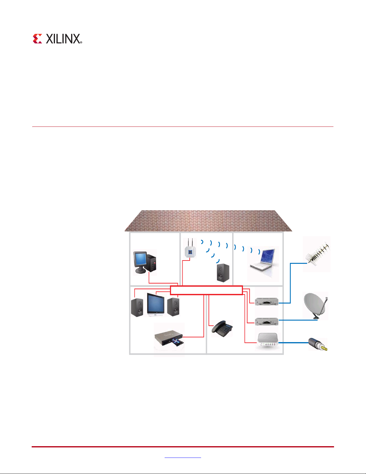
Figure 3-1 illustrates a potential home network, consisting of wired (ethernet) and wireless
components, which utilize the technology being defined by the IEEE802.1 Audio Video
Bridging Task Group. This illustrates potential audio/video talkers (for example, a Cable or
Satellite Content Provider, or home MP3 player) and a number of potential listeners (for
example TV sets which may exist in several rooms). In addition, users of the various
household PCs may be surfing the internet. It is important to note that all of this data is
being transferred across the single home network backbone.
X-Ref Target - Figure 3-1
Home Network
(wireless)
Home Network
Home Network (wired)
DVD player
Figure 3-1: Example AVB Home Network
Te rr e strial
Broadcast
Satellite
Broadband
Ethernet AVB Endpoint User Guide www.xilinx.com 29
UG492 July 23, 2010
Page 30

Chapter 3: Overview of Ethernet Audio Video Bridging
To understand the requirements of this network, we must differentiate between certain
types of data:
• Audio and Video streaming data, referred to in this document as AV traffic. Requires
a good quality of service to avoid, for example, TV picture breakup, and must be
transferred reliably and with guaranteed low latency.
• Other data, referred to in this document as legacy traffic. Does not have the strict
requirement of AV traffic: data can be started, stopped and delayed without serious
consequence for example, a PC surfing the internet.
For these reasons, an important aspect of the AVB technology is therefore to prioritize the
audio/video streaming data (AV traffic) over that of standard data transfer (legacy traffic).
AVB Specifications
The IEEE802.1 Audio Video Task Group is currently working on new specifications which
combine to define this technology:
P802.1AS
This specification defines how to synchronize a common time base across an entire AVB
network, utilizing functionality from IEEE1588 (version 2), and known as Precise Timing
Protocol (PTP). This common time base is in the form of a Real Time Clock (RTC),
effectively a large counter which consists of a 32-bit nanoseconds field and a 48-bit seconds
field. A single device on the network is designated as the clock master (by automatic
resolution) using a Best Master Clock Algorithm (BMCA). All other devices resolve to be
slaves. Using the P802.1AS PTP, all slave devices will regularly update their own RTC to
match that of the network clock master.
This common time base has various applications:
• It can be used to synchronize media clocks (audio clocks or video pixel clocks) across
the entire network to match audio and video data rates between talkers and listeners.
• It can be used by an Ethernet AVB Endpoint System, that is, configured as a "talker",
to time a class measurement interval for an SR stream. (The class measurement
interval for a stream depends upon the SR class associated with the stream: SR class A
corresponds to a class measurement interval of 125 microseconds; SR class B
corresponds to a class measurement interval of 250 microseconds). The class
measurement interval for a stream is used to limit the number of data frames that are
placed into the stream's queue per class measurement interval.
• It can be used by higher layer applications (for example IEEE1722) to provide
presentation time stamps for audio and video data. This is used, for example, to
synchronize the lip sync on a TV set so a viewer hears the words at the same time as
they see the lips move.
The P802.1AS specification is implemented in the Ethernet AVB Endpoint using a
combination of hardware and software. The hardware components are incorporated into
the core, and the software component is provided with the core in the form of drivers.
These drivers should be run on an embedded processor (MicroBlaze™ or PowerPC®).
30 www.xilinx.com Ethernet AVB Endpoint User Guide
UG492 July 23, 2010
Page 31

P802.1Qav
This specification defines the mechanism for queuing and forwarding AV traffic from a
talker to a listener across the network. This can involve several network hops (network
bridge devices that the data must pass through).
P802.1Qav is also responsible for enforcing the 75% maximum bandwidth restriction
across each link of the network that can be reserved for the AV traffic.
Only a subset of the P802.1Qav requirements for an Endpoint is implemented in the
Ethernet AVB Endpoint core, with the following assumptions for talkers and listeners:
Ta lk er Assumptions
• AV traffic Ethernet frames that are input to the Ethernet AVB Endpoint use the VLAN
• Legacy traffic Ethernet frames that are input to the Ethernet AVB Endpoint do not use
• The credit shaping algorithm operates on the AV traffic port; so in order to comply
• The Ethernet AVB Endpoint assumes that any per-stream traffic management has
• If multiple AV streams are input to the Ethernet AVB Endpoint via the AV traffic port,
AVB Specifications
priority values that the Bridges in the network recognize as being associated with SR
classes exclusively for transmitting stream data.
the VLAN priority values that the Bridges in the network recognize as being
associated with SR classes exclusively for transmitting stream data.
with the transmission selection rules for P802.1Qav, all Ethernet frames input on the
AV traffic port are assumed to be of the same SR Class. However, the Ethernet AVB
Endpoint does not enforce this rule and it is acceptable to send a mix of SR Class A
and SR Class B Ethernet frames on the AV traffic port. In this case the Ethernet AVB
Endpoint will not prioritize SR Class A Ethernet frames over SR Class B Ethernet
frames; instead it will apply the credit-based shaper algorithm to all of the Ethernet
frames that are input on the AV t r a ffic port.
been done prior to AV traffic being input on the AV traffic port. To comply with the
transmission selection rules for P802.1Qav it is assumed that if multiple streams are
input to the Ethernet AVB Endpoint via the AV traffic port, that the credit-based shaper
algorithm has been used per stream as the transmission selection mechanism, prior to
the AV traffic being input on the AV traffic port.
it is assumed that the IdleSlope/SendSlope control registers (See “Tx Arbiter Send
Slope Control Register” and “Tx Arbiter Idle Slope Control Register”) are
programmed correctly to be the sum of the IdleSlope /SendSlope values for all the
streams that are input on the AV traffic port. The credit-based shaper algorithm used
on the AV traffic port will enforce a hiLimit/loLimit on the credits to ensure that this
interface is not misused.
Listener Assumptions
• The Ethernet AVB Endpoint provides a mechanism for identifying received AV traffic
for either one or two SR classes (see “Rx Filtering Control Register”); however, it does
not provide any buffering for AV traffic Ethernet frames. Buffering is expected to be
done outside the Ethernet AVB Endpoint, after it has separated out the AV traffic
Ethernet frames, as the buffering requirements are expected to be application-specific.
Ethernet AVB Endpoint User Guide www.xilinx.com 31
UG492 July 23, 2010
Page 32

Chapter 3: Overview of Ethernet Audio Video Bridging
P802.1Qat
This specification defines a Stream Reservation Protocol (SRP) which must be used over
the AVB network. Every listener that intends to receive audio/video AV traffic from a
talker must make a request to reserve that bandwidth. Both the talker and every bridge
device that exists between the talker and the listener has the right to decline this request.
Only if each device is capable of routing the new AV traffic stream without violating the
75% total bandwidth restriction (when taking into account previously granted bandwidth
commitments), will the bandwidth request be successful. However, after granted, this
audio / video stream is reliably routed across the network until the reservation is
removed.
Note:
No hardware components are required for the P802.1Qat specification because this is a pure
software task. This software is not provided by the Ethernet AVB Endpoint core.
Typical Implementation
X-Ref Target - Figure 3-2
Xilinx Device
Audio /
Video
Sources /
Sinks
IEEE 1722
Packet
Manager
Embedded
Processor
System
with TCP/IP
stack
PLB management
AV
traffic
legacy
traffic
Ethernet
AVB
Endpoint
LogiCORE
Tri-Mode
Ethernet
MAC
LogiCORE
Ethernet
PHY
AVB
network
Figure 3-2: Example Ethernet AVB Endpoint System
Figure 3-2 illustrates a typical implementation for the Ethernet AVB Endpoint core.
Endpoint refers to a talker or listener device from the example network shown in
Figure 3-1, as opposed to an intermediate bridge function, which is not supported.
In the implementation, the Ethernet AVB Endpoint core is shown connected to a Xilinx TriMode Ethernet MAC core, which in turn is connected to an AVB capable network. All
devices attached to this network should be AVB capable to obtain the full Quality of
Service advantages for the AV traffic. This AVB network can be a professional or consumer
network (as illustrated in Figure 3-1).
32 www.xilinx.com Ethernet AVB Endpoint User Guide
UG492 July 23, 2010
Page 33

Typical Implementation
Figure 3-2 illustrates that the Ethernet AVB Endpoint core supports the two main types of
data interfaces at the client side:
1. The AV traffic interface is intended for the Quality of Service audio/video data.
Illustrated are a number of audio/video sources (for example, a DVD player), and a
number of audio/video sinks (for example, a TV set). The Ethernet AVB Endpoint
gives priority to the AV traffic interface over the legacy traffic interface, as dictated by
IEEE P802.1Qav 75% bandwidth restrictions.
2. The legacy traffic interface is maintained for best effort ethernet data: Ethernet as we
know it today (for example, the PC surfing the internet in Figure 3-1). Wherever
possible, priority is given to the AV traffic interface (as dictated by IEEE P802.1Qav
bandwidth restrictions) but a minimum of 25% of the total Ethernet bandwidth is
always available for legacy ethernet applications.
The AV traffic interface in Figure 3-2 is shown as interfacing to a 1722 Packet Manager
block. The IEEE1722 is also an evolving standard which will specify the embedding of
audio/video data streams into Ethernet Packets. The 1722 headers within these packets
can optionally include presentation time stamp information. Contact Xilinx for further
system-level information.
Ethernet AVB Endpoint User Guide www.xilinx.com 33
UG492 July 23, 2010
Page 34

Chapter 3: Overview of Ethernet Audio Video Bridging
34 www.xilinx.com Ethernet AVB Endpoint User Guide
UG492 July 23, 2010
Page 35

Generating the Core
The Ethernet AVB Endpoint core is fully configurable using the CORE Generator™
software, which provides a Graphical User Interface (GUI) for defining parameters and
options. For help starting and using the CORE Generator software, see the documentation
supplied with the ISE® software, including the CORE Generator User Guide, available from
www.xilinx.com/support/software_manuals.htm
Ethernet AVB GUI Page 1
Figure 4-1 shows page 1 of the Ethernet AVB Endpoint GUI customization screen.
X-Ref Target - Figure 4-1
Chapter 4
.
Figure 4-1: GUI Page 1
Ethernet AVB Endpoint User Guide www.xilinx.com 35
UG492 July 23, 2010
Page 36

Chapter 4: Generating the Core
Component Name
The component name is used as the base name of the output files generated for the core.
Names must begin with a letter and must be composed from the following characters: a
through z, 0 through 9 and “_”.
Core Delivery Format
The Ethernet AVB Endpoint core can be delivered in two different formats, selectable from
this section of the CORE Generator software Customization GUI:
• Standard CORE Generator software format (provided for the standard ISE software
environment)
This option will deliver the core in the standard CORE Generator software output
format, as used by many other cores including previous versions of this core and all
other Ethernet LogiCORE™ IP solutions.
When generated in this format, the core is designed to interface to the LogiCORE IP
Tri-Mode Ethernet MAC or the LogiCORE IP Embedded Tri-Mode Ethernet MAC
wrappers (available in selected Virtex® families). See Chapter 12, “System
Integration”.
When generated in this format, “Ethernet AVB GUI Page 2” is available for
customization of the “PLB Interface”.
• Generate as an EDK pcore (provided for the Embedded Development Kit)
This option will deliver the core in the standard pcore format, suitable for directly
importing into the Xilinx Embedded Development Kit (EDK) environment.
When generated in this format, the core is designed to interface to the XPS LocalLink
Tri-Mode Ethernet MAC (xps_ll_temac). See Chapter 12, “System Integration”.
When generated in this format, page 2 of the GUI is not available; the “PLB Interface”
will be configured dynamically by the EDK Xilinx Platform Studio (XPS) software.
For directory and file definitions for the two available formats, see Chapter 15, “Detailed
Example Design (Standard Format)” and Chapter 16, “Detailed Example Design (EDK
format).”
36 www.xilinx.com Ethernet AVB Endpoint User Guide
UG492 July 23, 2010
Page 37

Ethernet AVB GUI Page 2
Figure 4-2 shows page 2 of the Ethernet AVB Endpoint GUI customization screen. This
page provides options for configuring the “PLB Interface” of the core. This option is only
required when generating in the Standard CORE Generator software format.
X-Ref Target - Figure 4-2
Ethernet AVB GUI Page 2
Number of PLB Masters
The Ethernet AVB Endpoint core is a PLB slave. On the connected PLB, there may be
several PLB Masters. Each slave must uniquely acknowledge individual masters using
unique PLB signals during transactions. For this reason, set this integer value to match the
number of PLB masters that will be present on the PLB.
PLB Base Address
The Ethernet AVB Endpoint core is a PLB slave. The base address of the core must be
selected. Valid range is 0x00000000 to 0xFFFF8000. The least significant 15 bits of the base
address must be set to 0 (bits 17 to 31 of the PLB Base Address).
Figure 4-2: GUI Page 2
Ethernet AVB Endpoint User Guide www.xilinx.com 37
UG492 July 23, 2010
Page 38

Chapter 4: Generating the Core
Parameter Values in the XCO File
XCO file parameter names and their values are identical to the names and values shown in
the GUI.
Tab le 4- 1 shows the XCO file parameters and values and summarizes the GUI defaults.
The following is an example of the CSET parameters in an XCO file:
CSET component_name=eth_avb_endpoint_v2_4
CSET number_of_plb_masters=2
CSET plb_base_address=00000000
Table 4-1: XCO File Values and Default Values
Parameter XCO File Values Default GUI Setting
component_name ASCII text starting with a letter and
generate_as_edk_pcore Select between true and false false
number_of_plb_masters Select from the range: 1 to 16 2
plb_base_address Select from the range: 0x00000000
Output Generation
The output files generated by the CORE Generator software are placed in the project
directory. The list of output files includes the following items.
• The netlist file for the core
• Supporting CORE Generator software files
• Release notes and documentation
• Subdirectories containing an HDL example design
• Scripts to run the core through the back-end tools and to simulate the core using
Mentor Graphics ModelSim v6.5c, Cadence Incisive Enterprise Simulator (IES) v9.2,
and Synopsys VCS and VCS MX 2009.12
See the following chapters for a complete description of the CORE Generator software
output files and for detailed information about the HDL example design.
eth_avb_endpoint_v2_4
based on the following character
set: a..z, 0..9 and _
0x00000000
to 0xFFFF8000
• Chapter 14, “Quick Start Example Design”
• Chapter 15, “Detailed Example Design (Standard Format)”
• Chapter 16, “Detailed Example Design (EDK format)”
38 www.xilinx.com Ethernet AVB Endpoint User Guide
UG492 July 23, 2010
Page 39

Core Architecture
As described in Chapter 4, “Generating the Core”, the core can be generated in one of two
formats, the functionality of which is described in this chapter:
• “Standard CORE Generator Format” (provided for the standard ISE® software
environment)
This option will deliver the core in the standard CORE Generator™ output format, as
used by many other cores including previous versions of this core and all other
Ethernet LogiCORE™ IP solutions.
When generated in this format, the core is designed to interface to the LogiCORE IP
Tri-Mode Ethernet MAC or the LogiCORE IP Embedded Tri-Mode Ethernet MAC
wrappers (available in selected Virtex® families). See Figure 5-1.
• “EDK pcore Format”(provided for the Embedded Development Kit)
This option will deliver the core in the standard pcore format, suitable for directly
importing into the Xilinx Embedded Development Kit (EDK) environment.
Chapter 5
When generated in this format, the core is designed to interface to the XPS LocalLink
Tri-Mode Ethernet MAC (xps_ll_temac). See Figure 5-2.
Ethernet AVB Endpoint User Guide www.xilinx.com 39
UG492 July 23, 2010
Page 40

Chapter 5: Core Architecture
PLB I/F
Standard CORE Generator Format
Figure 5-1 illustrates the functional blocks of the Ethernet AVB Endpoint core when it is
generated in standard CORE Generator format. As illustrated, this is intended to be
connected to the LogiCORE IP Tri-Mode Ethernet MAC (or to the LogiCORE IP Embedded
Ethernet Wrappers available in certain Virtex devices).
Each of the functional blocks illustrated will be introduced in the following sections of this
chapter. However, observe from the figure that:
• The Host I/F (management interface) of the Tri-Mode Ethernet MAC is connected
directly to the Ethernet AVB Endpoint LogiCORE IP. This enables the MAC to be fully
configured via the “PLB Interface” of the Ethernet AVB Endpoint core.
• The core provides two independent full-duplex interfaces for customer logic: the “AV
Traffic Interface” and the “Legacy Traffic Interface”.
• The “Legacy Traffic Interface” contains “MAC Header Filters”; these are provided to
replace the Address Filter functionality of the LogiCORE IP Tri-Mode Ethernet MACs
(which must be disabled).
X-Ref Target - Figure 5-1
Ethernet AVB Endpoint
.c, .h
software
drivers
Embedded
Processor
Micro
Traffic
Legacy
Traffic
AV
Rx
Tx
Tx
Rx
PLB
AV Traffic I/F
PLB I/F
Legacy Traffic I/F
MAC Header Filters
Precise Timing Protocol (PTP)
Tx PTP Packet Buffer
Rx PTP Packet Buffer
Tx Arbiter
Tx Time Stamp
Real Time Counter
Rx Time Stamp
Rx Splitter
Tri-Mode
Ethernet
MAC
Tx Client Tx PHY
Rx PHYRx Client
Host I/F
Figure 5-1: Ethernet AVB Endpoint Core Block Diagram for Connection to LogiCORE IP Tri-Mode Ethernet
MAC
40 www.xilinx.com Ethernet AVB Endpoint User Guide
UG492 July 23, 2010
Page 41

EDK pcore Format
PLB I/F
Figure 5-2 illustrates the functional blocks of the Ethernet AVB Endpoint core when it is
generated in EDK pcore format. As illustrated, this is intended to be connected to the XPS
LocalLink Tri-Mode Ethernet MAC.
Each of the functional blocks illustrated will be introduced in the following sections of this
chapter. However, observe from the figure that:
• The xps_ll_temac contains its own PLB interface. Consequently, the logic connecting
the “PLB Interface” of the Ethernet AVB Endpoint core to the Host I/F (as seen in
Figure 5-1) is not present in this case.
• The “Legacy Traffic Interface” of the Ethernet AVB Endpoint core is connected
directly to the xps_ll_temac; this allows the xps_ll_temac core to source and sink
legacy frame data, such as TCP/IP protocol traffic. The full duplex “AV Traffic
Interface” remains for connection to custom logic.
• The “MAC Header Filters”, as seen in Figure 5-1, are not present in this case. The
xps_ll_temac instead contains its own Address Filter logic.
X-Ref Target - Figure 5-2
EDK pcore Format
Ethernet AVB Endpoint
.c, .h
software
drivers
Embedded
Processor
Micro
Traffic
Legacy
Traffic
AV
Tx
Rx
PLB
Tx
Rx
AV Traffic I/F
Precise Timing Protocol (PTP)
Tx PTP Packet Buffer
PLB I/F
Rx PTP Packet Buffer
Legacy Traffic I/F
Tx Arbiter
Tx Time Stamp
Real Time Counter
Rx Time Stamp
Rx Splitter
XPS LocalLink
Tri-Mode
Ethernet MAC
Avb2TemacTxData
Tem ac2AvbRxData
Avb2TemacRxData
Tem ac2AvbTxData
Tx PHY
Rx PHY
PLB
Figure 5-2: Ethernet AVB Endpoint Core Block Diagram for Connection to the XPS Tri-Mode Ethernet MAC
(xps_ll_temac) in the EDK
Ethernet AVB Endpoint User Guide www.xilinx.com 41
UG492 July 23, 2010
Page 42

Chapter 5: Core Architecture
Functional Block Description
The following functional blocks described in the following sections are illustrated in
Figure 5-1 and Figure 5-2.
PLB Interface
The core provides a PLB version 4.6 interface as its configuration port to provide easy
integration with the Xilinx Embedded Development Kit and access to an embedded
processor (MicroBlaze™ or PowerPC®), which is required to run the “Software Drivers.”
All the configuration and status register address space of the Ethernet AVB Endpoint core
can be accessed through the PLB.
Additionally, when the core is generated in “Standard CORE Generator Format”, the PLB
logic provides a logic shim which is connected to the Host I/F of the supported Xilinx TriMode MAC core; this enables all configuration and status registers of the MAC to also be
available via the PLB. See Chapter 10, “Configuration and Status” for more information.
AV Traffic Interface
The AV traffic interface provides a dedicated full duplex port for the high priority AV data.
See Chapter 6, “Ethernet AVB Endpoint Transmission,” and Chapter 7, “Ethernet AVB
Endpoint Reception” for further information.
Legacy Traffic Interface
The legacy traffic interface provides a dedicated full-duplex port for the legacy data, as
described in Chapter 6, “Ethernet AVB Endpoint Transmission,” and Chapter 7, “Ethernet
AVB Endpoint Reception”.
When the core is generated in “Standard CORE Generator Format” then “Legacy MAC
Header Filters” are provided on the receiver path. These filters have a greater flexibility
than the address filter provided in the LogiCORE Tri-Mode Ethernet MACs (which must
be disabled).
When the core is generated in “EDK pcore Format”, the legacy traffic interface is designed
to connect directly to the ports of the xps_ll_temac core; please see Figure 5-2 and
Chapter 12, “System Integration”. Additionally, the “Legacy MAC Header Filters” are not
included since the xps_ll_temac can optionally contain its own Address Filter logic.
42 www.xilinx.com Ethernet AVB Endpoint User Guide
UG492 July 23, 2010
Page 43

Tx Arbiter
Rx Splitter
Functional Block Description
Data for transmission over an AVB network can be obtained from three types of sources:
1. AV Tr af fi c. For transmission from the AV Traffic I/F of the core.
2. Precise Timing Protocol (PTP) Packets. Initiated by the software drivers using the
dedicated hardware “Tx PTP Packet Buffers.”
3. Legacy Traffic. For transmission from the Legacy Traffic I/F of the core.
The transmitter (Tx) arbiter must prioritize these packets. To aid with this, the arbiter
contains configuration registers that can be used to set the percentage of available Ethernet
bandwidth reserved for AV traffic. To comply with the specifications, this should not be
configured to exceed 75%. The arbiter then polices this bandwidth restriction for the AV
traffic and ensures that on average, it is never exceeded. Consequently, despite the AV
traffic having a higher priority than the legacy traffic, there is always remaining bandwidth
available to schedule legacy traffic. The output of the arbiter should be connected directly
to the client Tx interface of the connected Ethernet MAC, as illustrated. See Chapter 6,
“Ethernet AVB Endpoint Transmission,” for further information.
The input to the splitter is connected directly to the client Receive (Rx) interface of the
connected Ethernet MAC. Received data from an AVB network can be of three types:
• Precise Timing Protocol (PTP) Packets. Routed to the dedicated hardware “Rx PTP
Packet Buffers” which can be accessed by the “Software Drivers.” PTP packets are
identified by searching for a specific value in the MAC Length/Type field.
• AV Traffic. Routed to the AV Traffic I/F of the core. These packets are identified by
searching for MAC packets containing a MAC VLAN field with one of two possible
configurable VLAN priority values; the VLAN priorities are defaulted to values of 3
and 2.
• Legacy Traffic:. Routed to the Legacy Traffic I/F of the core. All packet types which
are not identified as PTP or AV Traffic will be considered legacy traffic.
See Chapter 7 for further information.
MAC Header Filters
The MAC Header Filters provided on the receiver legacy traffic path when the core is
generated in “Standard CORE Generator Format”. These filters provide a greater flexibility
than the standard address filter provided in the LogiCORE IP Tri-Mode Ethernet MACs
(which must be disabled). The MAC Header Filters include the ability to filter across any of
the initial 16-bytes of an Ethernet frame, including the ability to filter only on the
Destination Address, Length/Type Field, VLAN tag (if present), or any bit-wise match
combination of the preceding. Eight individual MAC Header Filters are provided, each of
which is separately configured. See Chapter 7, “Ethernet AVB Endpoint Reception” for
further information.
When the core is generated in “EDK pcore Format”, the “Legacy MAC Header Filters” are
not included since the xps_ll_temac can optionally contain its own Address Filter logic.
Ethernet AVB Endpoint User Guide www.xilinx.com 43
UG492 July 23, 2010
Page 44

Chapter 5: Core Architecture
Precise Timing Protocol Blocks
The various hardware Precise Timing Protocol (PTP) blocks within the core provide the
dedicated hardware to implement the IEEE P802.1AS specification. However, the full
functionality is only achieved using a combination of these hardware blocks coupled with
functions provided by the “Software Drivers” (run on an embedded processor).
Consequently the following hardware block descriptions also give some insight into the
software driver functionality.
Note:
detailed information about the PTP protocol, see the IEEE P802.1AS specification.
The following definitions provide only a simplistic concept of PTP protocol operation. For
Tx PTP Packet Buffers
The PTP packet buffer contains pre-initialized templates for seven different PTP packets
defined by the P802.1AS specification. The buffer contents are read/writable through the
PLB and a separate configuration register within the core requests to the Tx Arbiter which
of these seven packets is to be transmitted. A dedicated interrupt signal will be generated
by the core whenever a PTP packet has been transmitted.
The software drivers provided with the core, using the PLB and dedicated interrupts, will
use this interface to periodically update specific fields within the PTP packets, and request
transmission of these packets. See Chapter 9, “Precise Timing Protocol Packet Buffers” for
further information.
Tx Time Stamp
Whenever a PTP packet is transmitted, a sample of the current nanosecond value of the
local RTC is taken. This timestamp value is written into a dedicated field within the Tx PTP
Packet Buffer, where it is accessible along side the content of the PTP frame that was just
transmitted. By the time the Tx PTP buffer raises its dedicated interrupt, this time stamp is
available for the microprocessor to read. This sampling of the RTC is performed in
hardware for accuracy. See Chapter 9, “Precise Timing Protocol Packet Buffers” for further
information.
Rx PTP Packet Buffers
Received PTP Packets will be written to the Rx PTP Packet Buffer by the Rx Splitter. This
buffer is capable of storing up to 16 separate PTP frames. Whenever a PTP packet is
received, a dedicated interrupt will be generated. The contents of the stored packets can be
read via the PLB. The oldest stored frame will always be overwritten by a new frame
reception and so a configuration register within the core will contain a pointer to the most
recently stored packet.
The software drivers provided with the core, using the PLB and dedicated interrupt, will
use this interface to decode, and then act on, the received PTP packet information. See
Chapter 9, “Precise Timing Protocol Packet Buffers” for further information.
Rx Time Stamp
When a PTP packet is received, a sample of the current nanosecond value of the RTC is
taken. This timestamp value is written into a dedicated field within the Rx PTP Packet
Buffer, where it is accessible along side the PTP frame that was just received. By the time
the Rx PTP buffer raises its dedicated interrupt, this time stamp is available for the
microprocessor to read. This sampling of the RTC is performed in hardware for accuracy.
See Chapter 9, “Precise Timing Protocol Packet Buffers” for further information.
44 www.xilinx.com Ethernet AVB Endpoint User Guide
UG492 July 23, 2010
Page 45

Functional Block Description
RTC
A significant component of the PTP network wide timing synchronization mechanism is
the Real Time Counter (RTC), which provides the common time of the network. Every
device on the network will maintain its own local version.
The RTC is effectively a large counter which consists of a 32-bit nanosecond field (the unit
of this field is 1 nanosecond and this field will count the duration of exactly one second,
then reset back to zero) and a 48-bit second field (the unit of this field is one second: this
field will increment when the nanosecond field saturates at 1 second). The seconds field
will only wrap around when its count fully saturates. The entire RTC is therefore designed
never to wrap around in our lifetime. The RTC counter is implemented as part of the core
in hardware.
Conceptually, this counter is not related to the frequency of the clock used to increment it.
A configuration register within the core provides a configurable increment rate for this
counter; this increment register simply takes the value of the clock period which is being
used to increment the RTC. However, the resolution of this increment register is very fine,
in units of 1/1048576 (1/2
increment rate can be adjusted to a very fine degree of accuracy. This provides the
following features:
• The RTC can be incremented from any available clock frequency that is greater than
the AVB standards defined minimum of 25 MHz. However, the faster the frequency of
the clock, the smaller will be the step increment and the smoother will be the overall
RTC increment rate. Xilinx recommends clocking the RTC logic at 125 MHz because
this is a readily available clock source (obtained from the transmit clock source of the
Ethernet MAC at 1 Gbps speed). This frequency significantly exceeds the minimum
performance of the P802.1AS specification.
• When acting as a clock slave, the rate adjustment of the RTC can be matched to that of
the network clock master to an exceptional level of accuracy. The software drivers
provided with this core will periodically calculate the increment rate error between
itself and the master and update the RTC increment value accordingly.
20
) fraction of one nanosecond. For this reason, the RTC
The core also contains a configuration register which allows a large step change to be made
to the RTC. This can be used to initialize the RTC, after power-up. It is also used to make
periodic corrections, as required, by the software drivers when operating as a clock slave;
if the increment rates are closely matched, these periodic step corrections will be small. See
Chapter 9, “Precise Timing Protocol Packet Buffers” for further information.
Ethernet AVB Endpoint User Guide www.xilinx.com 45
UG492 July 23, 2010
Page 46

Chapter 5: Core Architecture
Software Drivers
Software Drivers are delivered with the Ethernet AVB Endpoint core. These drivers
provide functions which utilize the dedicated hardware within the core for the PTP IEEE
P802.1AS specification. Functions include:
• The Best Master Clock Algorithm (BMCA) to determine whether the core should
operate in master clock or slave clock mode
• PTP Clock Master functions
• PTP Clock Slave functions (which accurately synchronize the local Real Time Clock
(RTC) to match that of the network clock master)
If the core is acting as clock master, then the software drivers delivered with the core will
periodically sample the current value of the RTC and transmit this value to every device on
the network using the P802.1 defined PTP packets. The hardware “Tx Time Stamp” logic,
using the mechanism defined in P802.1AS, ensures the accuracy of this RTC sample
mechanism.
If the core is acting as a clock slave, then the local RTC will be closely matched to the value
and frequency of the network clock master. This is achieved, in part, by receiving the PTP
frames transmitted across the network by the clock master (and containing the masters
sampled RTC value). The PTP mechanism will also track the total routing delay across the
network between the clock master and itself. The software drivers use this data, in
conjunction with recent historical data, to calculate the error between its local RTC counter
and that of the RTC clock master. The software will then periodically calculate an RTC
correction value and an updated increment rate, and these values are written to
appropriate RTC configuration registers. See Chapter 13, “Software Drivers” for further
information.
Tri-Mode Ethernet MACs
Although not part of the Ethernet AVB Endpoint core, a Xilinx Tri-Mode Ethernet MAC
core is a requirement of the system (see Figure 5-1 and Figure 5-2). The IEEE Audio Video
Bridging technology stipulates the following configuration requirements on this MAC:
• The MAC must only operate in full-duplex mode
• The MAC must only operate at 100 Mbps and/or 1 Gbps
• VLAN mode must be enabled (the AV traffic will always contain VLAN fields)
• Flow Control is not supported on the network and must be disabled
• Jumbo Frames are not supported and must be disabled
• The built-in Address Filter Module of the MAC must be disabled
46 www.xilinx.com Ethernet AVB Endpoint User Guide
UG492 July 23, 2010
Page 47

Core Interfaces
All ports of the core are internal connections in FPGA fabric.
All clock signals are inputs and no clock resources are used by the core. This enables clock
circuitry to be implemented externally to the core netlist, providing full flexibility for clock
sharing with other custom logic.
Clocks and Reset
Tab le 5- 1 defines the clock and reset signals which are required by the Ethernet AVB
Endpoint core.
Table 5-1: Clocks and Resets
Core Interfaces
Signal Direction Description
reset Input Asynchronous reset for the entire core
rtc_clk Input Reference clock used to increment the “RTC.” The
minimum frequency is 25 MHz. Xilinx recommends a
125 MHz clock source.
tx_clk Input The MAC transmitter clock, provided by the Tri-Mode
Ethernet MAC.
tx_clk_en Input A clock enable signal: this must be used as a qualifier
for tx_clk.
rx_clk Input The MAC receiver clock, provided by the Tri-Mode
Ethernet MAC.
rx_clk_en Input A clock enable signal: this must be used as a qualifier
for rx_clk.
host_clk Input An input clock for the management interface of the
connected Tri-Mode Ethernet MAC. This clock can be
independent, or could be shared with PLB_clk.
This signal is only present when the core is generated in
“Standard CORE Generator Format”.
PLB_clk Input The input clock reference for the PLB bus.
tx_reset Output Output reset signal for logic on the Legacy Traffic and
AV Traffic transmitter paths. This reset signal is
synchronous to tx_clk; the reset is asserted when a
transmitter path reset request is made to the “Software
Reset Register.”
rx_reset Output Output reset signal for logic on the Legacy Traffic and
AV Traffic receiver paths. This reset signal is
synchronous to rx_clk; the reset is asserted when a
receiver path reset request is made to the “Software
Reset Register.”
Ethernet AVB Endpoint User Guide www.xilinx.com 47
UG492 July 23, 2010
Page 48

Chapter 5: Core Architecture
Legacy Traffic Interface
Legacy Traffic Transmitter Path Signals
Tab le 5- 2 defines the core client-side legacy traffic transmitter signals. These signals are
used to transmit data from the legacy client logic into the core. All signals are synchronous
to the MAC transmitter clock, tx_clk, which must be qualified by the corresponding
clock enable, tx_clk_en (see “Clocks and Resets”).
Table 5-2: Legacy Traffic Signals: Transmitter Path
legacy_tx_data[7:0] Input Frame data to be transmitted is supplied on
legacy_tx_data_valid Input A data valid control signal for data on the
legacy_tx_underrun Input Asserted by the client to force the MAC to
legacy_tx_ack Output Handshaking signal asserted when the
Signal Direction Description
this port
legacy_tx_data[7:0] port
corrupt the current frame
current data on legacy_tx_data[7:0]
has been accepted.
Legacy Traffic Receiver Path Signals
Tab le 5- 3 defines the core client side legacy traffic receiver signals. These signals are used
by the core to transfer data to the client. All signals are synchronous to the MAC receiver
clock, rx_clk, which must be qualified by the corresponding clock enable, rx_clk_en
(see “Clocks and Resets”).
Table 5-3: Legacy Traffic Signals: Receiver Path
Signal Direction Description
legacy_rx_data[7:0] Output Legacy frame data received is supplied
on this port.
legacy_rx_data_valid Output Control signal for the
legacy_rx_data[7:0] port
48 www.xilinx.com Ethernet AVB Endpoint User Guide
UG492 July 23, 2010
Page 49

Core Interfaces
Table 5-3: Legacy Traffic Signals: Receiver Path
Signal Direction Description
legacy_rx_frame_good Output Asserted at the end of frame reception to
indicate that the frame should be
processed by the MAC client.
legacy_rx_frame_bad Output Asserted at the end of frame reception to
indicate that the frame should be
discarded by the MAC client: either the
frame contained an error, or it was
intended for the PTP or AV traffic
channel.
legacy_rx_filter_match[7:0] Output This output is only present when the
“MAC Header Filters” are present (when
the core is generated in “Standard CORE
Generator Format”).
When present, each bit in the bus
corresponds to one of the unique
“Legacy MAC Header Filters.” A bit is
asserted, in alignment with
legacy_rx_data_valid signal, if the
corresponding filter number obtained a
match.
AV Traffic Interface
AV Traffic Transmitter Path Signals
Tab le 5- 4 defines the core client-side AV traffic transmitter signals, used to transmit data
from the AV client logic into the core. All signals are synchronous to the MAC transmitter
clock, tx_clk, which must be qualified by the corresponding clock enable, tx_clk_en
(see “Clocks and Resets”).
Table 5-4: AV Traffic Signals: Transmitter Path
Signal Direction Description
av_tx_data[7:0] Input Frame data to be transmitted is supplied on this
av_tx_valid Input A data valid control signal for data on the
av_tx_done Input Asserted by the AV client to indicate that further
av_tx_ack Output Handshaking signal asserted when the current
port
av_tx_data[7:0] port
frames, following the current frame, are/are not
held in a queue.
data on av_tx_data[7:0] has been accepted.
Ethernet AVB Endpoint User Guide www.xilinx.com 49
UG492 July 23, 2010
Page 50

Chapter 5: Core Architecture
AV Traffic Receiver Path Signals
Tab le 5- 5 defines the core client side AV traffic receiver signals, used by the core to transfer
data to the AV client. All signals are synchronous to the MAC receiver clock, rx_clk,
which must be qualified by the corresponding clock enable, rx_clk_en (see “Clocks and
Resets”).
Table 5-5: AV Traffic Signals: Receiver Path
av_rx_data[7:0] Output AV frame data received is supplied on this port.
av_rx_valid Output Control signal for the av_rx_data[7:0] port
av_rx_frame_good Output Asserted at the end of frame reception to indicate
av_rx_frame_bad Output Asserted at the end of frame reception to indicate
Signal Direction Description
that the frame should be processed by the MAC
client.
that the frame should be discarded by the MAC
client: either the frame contained an error, or it was
intended for the PTP or legacy traffic channel.
Tri-Mode Ethernet MAC Client Interface
Tab le 5- 6, Ta bl e 5 -7 and Tab le 5 -8 list the ports of the core which connect directly to the
port signals of the Tri-Mode Ethernet MAC core, which are identically named. For detailed
information about the Tri-Mode Ethernet MAC ports, see the Tri-Mode Ethernet MAC
User Guide (UG138).
MAC Transmitter Interface
These signals connect directly to the identically named Tri-Mode Ethernet MAC signals
and are synchronous to tx_clk.
Table 5-6: Tri-Mode Ethernet MAC Transmitter Interface
Signal Direction Description
tx_data[7:0] Output Frame data to be transmitted is supplied on this port
tx_data_valid Output A data valid control signal for data on the
tx_data[7:0] port
tx_underrun Output Asserted to force the MAC to corrupt the current frame
tx_ack Input Handshaking signal asserted when the current data on
tx_data[7:0] has been accepted by the MAC.
50 www.xilinx.com Ethernet AVB Endpoint User Guide
UG492 July 23, 2010
Page 51

Core Interfaces
MAC Receiver Interface
These signals connect directly to the identically named Tri-Mode Ethernet MAC signals
and are synchronous to rx_clk
Table 5-7: Tri-Mode Ethernet MAC Receiver Interface
Signal Direction Description
rx_data[7:0] Input Frame data received is supplied on this port.
rx_data_valid Input Control signal for the rx_data[7:0] port
rx_frame_good Input Asserted at the end of frame reception to indicate
that the frame should be processed by the
Ethernet AVB Endpoint core.
rx_frame_bad Input Asserted at the end of frame reception to indicate
that the frame should be discarded by the MAC
client.
MAC Management Interface
This interface is only present when the core is generated in “Standard CORE Generator
Format”, designed for connection to LogiCORE IP Tri-Mode Ethernet MAC devices.
When present, these signals connect directly to the identically named LogiCORE IP TriMode Ethernet MAC signals (except where stated in Tab le 5 -8 ) and are synchronous to
host_clk. When present, all MAC configuration and MDIO register space is address
mapped into the PLB of the Ethernet AVB Endpoint core. A logic shim automatically drives
this interface to access the MAC when the appropriate PLB address space is accessed.
Table 5-8: Tri-Mode Ethernet MAC Host Interface (Configuration/Status)
Signal Direction Description
host_opcode[1:0] Output Defines the MAC operation
(configuration or MDIO, read or write)
host_addr[9:0] Output Address of the MAC register to access
host_wr_data[31:0] Output Data to be written to the MAC register
host_rd_data_mac[31:0] Input Data read from the MAC register (connect
to the host_rd_data[31:0] signal of the
MAC)
host_rd_data_stats[31:0] Input Data read from the Ethernet Statistics core
(connect to the host_rd_data[31:0] signal
of the Ethernet Statistics core, if present).
If the statistics core is not used, then
connect to logic 0.
host_miim_sel Output When asserted, the MAC will access the
MDIO port, when not asserted, the MAC
will access configuration registers
host_req Output Used to initiate a transaction onto the
MDIO
Ethernet AVB Endpoint User Guide www.xilinx.com 51
UG492 July 23, 2010
Page 52

Chapter 5: Core Architecture
Table 5-8: Tri-Mode Ethernet MAC Host Interface (Configuration/Status)
host_miim_rdy Input When high, the MAC has completed its
host_stats_lsw_rdy Input Signal provided by the Ethernet Statistics
host_stats_msw_rdy Input Signal provided by the Ethernet Statistics
Processor Local Bus (PLB) Interface
Signal Direction Description
MDIO transaction
core to indicate that the lower 32-bits of
the statistic counter value is present on
the host_rd_data_stats[31:0] port. If the
statistics core is not used, then connect to
logic 0.
core to indicate that the upper 32-bits of
the statistic counter value is present on
the host_rd_data_stats[31:0] port. If the
statistics core is not used, then connect to
logic 0.
The Processor Local Bus (PLB) on the Ethernet Audio Video core is designed to be
integrated directly in the Xilinx Embedded Development Kit (EDK) where it can be easily
integrated and connected to the supported embedded processors (MicroBlaze or
PowerPC). As a result, the PLB interface does not require in-depth understanding, and the
following information is provided for reference only. See the EDK documentation
for
further information.
The PLB interface, defined by IBM, can be complex and support many usage modes (such
as multiple bus masters). It can support single or burst read/writes, and can support
different bus widths and different peripheral bus widths.
The general philosophy of the Ethernet AVB Endpoint core has been to implement a PLB
interface which is as simple as possible. The following features are provided:
• 32-bit data width.
• Implements a simple PLB slave.
• Supports single read/writes only (no burst or page modes).
52 www.xilinx.com Ethernet AVB Endpoint User Guide
UG492 July 23, 2010
Page 53

Core Interfaces
PLB Interface
Tab le 5- 9 defines the signals on the PLB bus. For detailed information, see the IBM PLB
specification. Shaded rows represent signals not used by this core; inputs are ignored and
outputs are tied to a constant. These signals are synchronous to PLB_clk; see “Clocks and
Resets” for additional information.
Table 5-9: PLB Signals
PIN Name Direction Description
PLB_clk Input Reference clock for the PLB
PLB_reset Input Reset for the PLB, synchronous to
PLB_clk
PLB_ABus[0:31] input PLB address bus
PLB_UABus[0:31] Input PLB upper address bus
PLB_PAvaild Input PLB primary address valid indicator
PLB_SAValid Input Unused. PLB secondary address valid
indicator.
PLB_rdPrim Input Unused. PLB secondary to primary read
request indicator.
PLB_wrPrim Input Unused. PLB secondary to primary write
request indicator.
PLB_masterID
[0:log2(NUM_MASTERS)]
PLB_abort Input PLB abort request indicator
PLB_busLock Input Unused. PLB bus lock.
PLB_RNW Input PLB read not write
PLB_BE[0:3] Input PLB byte enables
PLB_MSize[0:1] Input PLB master data bus size
PLB_size[0:3] Input PLB transfer size. Only support size 0.
PLB_type[0:2] Input PLB transfer type. Only support type 0.
PLB_TAttribute[0:15] Input Unused. PLB transfer attribute bus.
PLB_lockErr Input Unused. PLB lock error indicator.
PLB_wrDBus[0:31] Input PLB write data bus
PLB_wrBurst Input PLB write burst transfer indicator.
PLB_rdBurst Input PLB read burst transfer indicator.
PLB_rdPendReq Input Unused. PLB pending read request
Input PLB current master identifier
priority.
PLB_wrPendReq Input Unused. PLB pending write request
priority.
PLB_rdPendPri[0:1] Input Unused. PLB pending read bus request
indicator.
Ethernet AVB Endpoint User Guide www.xilinx.com 53
UG492 July 23, 2010
Page 54

Chapter 5: Core Architecture
Table 5-9: PLB Signals (Cont’d)
PLB_wrPendPri[0:1] Input Unused. PLB pending read bus request
PLB_reqPri[0:1] Input Unused. PLB request priority.
Sl_addrAck Output Slave address acknowledge
Sl_SSize[0:1] Output Slave data bus size.
Sl_wait Output Slave wait indicator.
Sl_rearbitrate Output Slave rearbitrate bus indicator. Not used,
Sl_wrDack Output Slave write data acknowledge
Sl_wrComp Output Slave write transfer complete indicator
Sl_WrBTerm Output Slave terminate write burst transfer.
Sl_rdBus[0:31] Output Slave read data bus
Sl_rdWdAddr[0:3] Output Slave read word address
PIN Name Direction Description
indicator.
tied to logic 0.
Sl_rdDAck Output Slave read data acknowledge
Sl_rdComp Output Slave read transfer complete indicator
Sl_rdBTerm Output Slave terminate read burst transfer.
Sl_MBusy[0:NUM_MASTERS-1] Output Slave busy indicator
Sl_MWrErr[0:NUM_MASTERS-1] Output Unused, tied to logic 0. Slave write error
indicator.
Sl_MRdErr[0:NUM_MASTERS-1] Output Unused, tied to logic 0. Slave read error
indicator.
Sl_MIRQ[0:NUM_MASTERS-1] Output Unused, tied to logic 0. Slave interrupt
indicator.
54 www.xilinx.com Ethernet AVB Endpoint User Guide
UG492 July 23, 2010
Page 55

Interrupt Signals
Tab le 5- 10 defines the interrupt signals asserted by the core. All interrupts are active high
and are automatically asserted. All interrupts, required by the “Software Drivers”
delivered with the core, are cleared by software access to an associated configuration
register. It is recommended that these interrupts are routed to the input of an EDK
Interrupt Controller module as part of the embedded processor subsystem.
Table 5-10: Interrupt Signals
interrupt_ptp_timer Output This interrupt is asserted every 1/128
interrupt_ptp_tx Output This is asserted following the transmission
interrupt_ptp_rx Output This is asserted following the reception of
Core Interfaces
Signal Direction Description
second as measured by the “RTC.” This acts
as a timer for the PTP software algorithms.
of any PTP packet from the “Tx PTP Packet
Buffers.”
any PTP packet into the “Rx PTP Packet
Buffers.”
Ethernet AVB Endpoint User Guide www.xilinx.com 55
UG492 July 23, 2010
Page 56

Chapter 5: Core Architecture
PTP Signals
Tab le 5- 11 defines the signals which are output from the core by the “Precise Timing
Protocol Blocks.” These signals are provided for reference only and may be used by an
application. For example, the 1722 Packet Managers, as illustrated in Figure 3-2, require
the following:
• clk8k: this marks the class measurement interval to be used for traffic shaping for SR
class A AV traffic.
• rtc_nanosec_field and rtc_sec_field: used in the 1722 presentation time
stamp logic.
Table 5-11: PTP Signals
rtc_nanosec_field[31:0] Output This is the synchronized nanoseconds field
rtc_sec_field[47:0] Output This is the synchronized seconds field
Signal Direction Description
from the “RTC.”
from the “RTC.”
clk8k Output This is an 8KHz clock which is derived
from, and synchronized in frequency, to
the “RTC.”
rtc_nanosec_field_1722[31:0] Output The IEEE1722 specification contains a
different format for the “RTC,”provided
here as an extra port. This is derived and is
in sync with the IEEE802.1 AS RTC. If
desired, this port can be used as the RTC
reference for 1722 Packet Manager blocks,
as illustrated in
“IEEE1722 Real Time Clock Format,”
page 81.
Figure 3-2. See also
56 www.xilinx.com Ethernet AVB Endpoint User Guide
UG492 July 23, 2010
Page 57

Chapter 6
Ethernet AVB Endpoint Transmission
As illustrated in Figure 5-1, data for transmission over an AVB network can be obtained
from three types of sources:
1. AV Tr af fi c. For transmission from the “Tx AV Traffic I/F” of the core.
2. Precise Timing Protocol (PTP) Packets. Initiated by the software drivers using the
dedicated hardware “Tx PTP Packet Buffer.”
3. Legacy Traffic. For transmission from the “Tx Legacy Traffic I/F” of the core.
Tx Legacy Traffic I/F
The signals forming the Tx Legacy Traffic I/F are defined in Tab le 5 -2 . All signals are
synchronous to the Tri-Mode Ethernet MAC transmitter clock, tx_clk, which must
always be qualified by the corresponding clock enable, tx_clk_en (see Ta bl e 5 -1 ).
This interface is intentionally identical to the client transmitter interface of the supported
Xilinx Tri-Mode Ethernet MAC core (there is a one-to-one correspondence between signal
names of the block-level wrapper from the Tri-Mode Ethernet MAC example design, after
the legacy_ prefix is removed). This provides backwards compatibility–all existing MAC
client-side designs can connect to the legacy Ethernet port unmodified.
Ethernet AVB Endpoint User Guide www.xilinx.com 57
UG492 July 23, 2010
Page 58

Chapter 6: Ethernet AVB Endpoint Transmission
Error Free Legacy Frame Transmission
X-Ref Target - Figure 6-1
tx_clk
tx_clk_enable
legacy_tx_data[7:0]
legacy_tx_data_valid
legacy_tx_ack
legacy_tx_underrun
DA SA DATAL/T
Figure 6-1: Normal Frame Transmission across the Legacy Traffic Interface
Figure 6-1 illustrates the timing of a normal frame transfer. When the legacy client initiates
a frame transmission, it places the first column of data onto the legacy_tx_data[7:0]
port and asserts a logic 1 onto legacy_tx_data_valid. After the Ethernet AVB
Endpoint core reads the first byte of data, it asserts the legacy_tx_ack signal. On the
next and subsequent rising clock edges, the client must provide the remainder of the data
for the frame. The end of frame is signalled to the core by taking the
legacy_tx_data_valid to logic 0.
58 www.xilinx.com Ethernet AVB Endpoint User Guide
UG492 July 23, 2010
Page 59

Errored Legacy Frame Transmission
X-Ref Target - Figure 6-2
tx_clk
tx_clk_enable
legacy_tx_data[7:0]
DA SA DATAL/T
legacy_tx_data_valid
legacy_tx_ack
legacy_tx_underrun
Tx AV Traffic I/F
The legacy_tx_underrun is provided to give full backwards compatibility between the
Legacy Traffic I/F and the client interface of the Tri-Mode Ethernet MAC. The
legacy_tx_underrun provides a mechanism to inject an error into a frame before
transmission is completed. This can occur, for example, if a FIFO connected to the Legacy
client empties during transmission.
To error the frame, the legacy_tx_underrun signal may be asserted during the data
transmission or up to 1 valid clock cycle after legacy_tx_data_valid goes low.
Tx AV Traffic I/F
The signals forming the Tx AV Traffic I/F are defined in Tab le 5 -4. All signals are
synchronous to the Tri-Mode Ethernet MAC transmitter clock, tx_clk, which must
always be qualified by the corresponding clock enable, tx_clk_en (see Ta bl e 5 -1 ). See
(“Talker Assumptions,” page 31) for information about the expectations for the AV traffic
input to the Ethernet AVB Endpoint on this interface.
This interface is intentionally very similar to the “Tx Legacy Traffic I/F.” Note, however,
that the legacy traffic does not contain a signal that is equivalent to av_tx_done.
Additionally, the AV does not contain a signal that is equivalent to
legacy_tx_underrun: no mechanism is currently provided on the AV interface to signal
an error in a frame which is currently undergoing transmission.
Figure 6-2: Legacy Frame Transmission with Underrun
Ethernet AVB Endpoint User Guide www.xilinx.com 59
UG492 July 23, 2010
Page 60

Chapter 6: Ethernet AVB Endpoint Transmission
X-Ref Target - Figure 6-3
tx_clk
tx_clk_enable
av_tx_data[7:0]
DA SA DATAL/T
av_tx_data_valid
av_tx_done
av_tx_ack
DA
Figure 6-3: Normal Frame Transmission across the AV Traffic Interface
Figure 6-3 illustrates the timing of a normal frame transfer. When the AV client initiates a
frame transmission, it places the first column of data onto the av_tx_data[7:0] port
and asserts a logic 1 onto av_tx_valid.
After the Ethernet AVB Endpoint core reads the first byte of data, it asserts the av_tx_ack
signal. On the next and subsequent rising clock edges, the client must provide the
remainder of the data for the frame. The end of frame is signalled to the core by taking the
av_tx_valid to logic 0.
In Figure 6-3, following the end of frame transmission, the av_tx_done signal is held low,
which indicates to the “Tx Arbiter” that another AV frame is queued. Unless the
configurable bandwidth restrictions have been exceeded, this parks the “Tx Arbiter” onto
the AV traffic queue. Figure 6-3 then illustrates the client asserting the av_tx_valid
signal to request a subsequent frame, and the frame transmission cycle of Figure 6-3
repeats. However, if no further AV traffic frames are queued, the av_tx_done signal
should be set to logic 1 immediately following the end of frame transmission. This than
allows the “Tx Arbiter” to schedule legacy traffic transmission (if any legacy frames are
queued).
If, following the end of frame reception, the bandwidth allocation for AV traffic has been
exceeded, the “Tx Arbiter” switches to service the legacy traffic regardless of the state of
the av_tx_done signal.
For this reason, the av_tx_done signal should be considered an aid to the “Tx Arbiter” to
help make best use of the available network bandwidth. Asserting this signal after all AV
traffic has been serviced immediately allows the “Tx Arbiter” to service the legacy traffic.
This helps achieve in excess of the 25% minimum allocation for the legacy traffic. However,
holding off the assertion of av_tx_done will not act as cheat mode to exceed the
maximum bandwidth allocation for the AV traffic.
60 www.xilinx.com Ethernet AVB Endpoint User Guide
UG492 July 23, 2010
Page 61

Tx Arbiter
Tx Arbiter
Overview
As illustrated in Figure 5-1, data for transmission over an AVB network can be obtained
from three types of sources:
1. AV Tr af fi c. For transmission from the AV Traffic I/F of the core.
2. Precise Timing Protocol (PTP) Packets. Initiated by the software drivers using the
dedicated hardware “Tx PTP Packet Buffer.”
3. Legacy Traffic. For transmission from the Legacy Traffic I/F of the core.
The transmitter (Tx) arbiter selects from these three sources in the following manner.
• If there is AV packet available and the programmed AV bandwidth limitation is not
exceeded, then the AV packet is transmitted
• otherwise the Tx arbiter checks to see if there are any PTP packets to be transmitted
• otherwise if there is an available legacy packet then this will be transmitted.
The Ethernet AVB Endpoint core contains configuration registers to set up the percentage
of available Ethernet bandwidth reserved for AV traffic. To comply with the IEEE P802.1
Qav specification these should not be configured to exceed 75%. The arbiter then polices
this bandwidth restriction for the AV traffic and ensures that on average, it is never
exceeded. Consequently, despite the AV traffic having a higher priority than the legacy
traffic, there is always remaining bandwidth available to schedule legacy traffic.
The relevant configuration registers for programming the bandwidth percentage
dedicated to AV traffic are defined in Chapter 10, “Configuration and Status” and are:
• “Tx Arbiter Send Slope Control Register”
• “Tx Arbiter Idle Slope Control Register”
These registers are defaulted to values which dedicate up to 75% of the overall bandwidth
to the AV traffic. This is the maximum legal percentage that will be defined in the
IEEE802.1 AVB st a nd ard s.
In many implementations, it may be unnecessary to change these register values. Correct
use of the av_tx_done signal, as defined in “Tx AV Traffic I/F,” will allow the Tx Arbiter
to share the bandwidth allocation efficiently between the AV and Legacy sources (even in
the situations where the AV traffic requires less than 75% of the overall bandwidth).
However, for the cases that require less than 75% of the overall bandwidth, careful
configuration can result in a smoother (less bursty) transmission of the AV traffic, which
should prevent frame bunching across the AVB network.
Credit Based Traffic Shaping Algorithm
To enforce the bandwidth policing of the AV Traffic, a credit-based shaper algorithm has
been implemented in the Ethernet AVB Endpoint core. Figure 6-4 illustrates the basic
operation of the algorithm and indicates how the Tx Arbiter decides which Ethernet frame
to transmit.
Ethernet AVB Endpoint User Guide www.xilinx.com 61
UG492 July 23, 2010
Page 62

Chapter 6: Ethernet AVB Endpoint Transmission
X-Ref Target - Figure 6-4
increasing
credit
idleSlope
hiLimit
credit=0
when no frames
are waiting
sendSlope
credits withdrawn
when no frames
are waiting
0
loLimit
number of AV
queued frames
1
0
transmitting
AV frame
TRUE
FALSE
transmitting
Legacy frame
TRUE
FALSE
increasing
time
conflicting legacy traffic present, so queued AV frame is not
transmitted until conflicting legacy frame has been transmitted
Figure 6-4: Credit-based Shaper Operation
Figure 6-4 illustrates the key features of the credit based algorithm, which are:
• The Tx Arbiter will schedule queued transmission from the “Tx AV Traffic I/F” if the
algorithm is in credit (greater or equal to 0).
• If there is less than 0 credit (not shown in Figure 6-4, but the credit can sink below 0),
then the Tx Arbiter will not allow AV traffic to be transmitted; legacy traffic, if
queued, will be scheduled instead.
• When no AV traffic is queued, any positive credit will be lost and the credit is reset to
0.
• When AV traffic is queued, and until the time at which the Tx Arbiter is able to
schedule it (while waiting for an in-progress legacy frame to complete transmission),
credit can be gained at a rate defined by the idleSlope.
62 www.xilinx.com Ethernet AVB Endpoint User Guide
UG492 July 23, 2010
Page 63

• During AV traffic transmission, credit is removed at a rate defined by the sendSlope.
• The hiLimit and loLimit settings impose a fixed range on the possible values of
credit. If the available credit hits one of these limits, it will not exceed, but saturate at
the magnitude of that limit. These limits are fixed in the netlist to ensure that the
interface is not used incorrectly.
The overall intention of the two settings idleSlope and sendSlope is to spread out the AV
traffic transmission as evenly as possible over time, preventing periods of bursty AV
transmission surrounded by idle AV transmission periods. No further background
information is provided in this document with regard to the credit-based algorithm.
The remainder of this section describes the idleSlope, and sendSlope variables from the
perspective of the Ethernet AVB Endpoint core.
Tx Arbiter Bandwidth Control
The Ethernet AVB Endpoint core contains four configuration registers, used for setting the
cores local definitions of “idleSlope,” and “sendSlope.”
The configuration register settings are described in general, and then from the point of
view of a single example which describes the calculations made to set the register default
values. This example dedicates up to 75% of the overall bandwidth to be reserved for the
AV traffic (leaving at least 25% for the Legacy Traffic).
Tx Arbiter
The calculations described are independent of Ethernet operating speed (no re-calculation
is required when changing between Ethernet speeds of 1 Gbps and 100 Mbps).
idleSlope
The general equation is:
idleSlopeValue=(AV percentage / 100) x 8192
In this example, dedicating up to 75% of the total bandwidth to the AV traffic, we obtain:
idleSlopeValue=(75 / 100) x 8192 = 6144
The calculated value for the idleSlopeValue should be written directly to the “Tx
Arbiter Idle Slope Control Register.” This provides a per-byte increment value when
relating this to Legacy Ethernet frame transmission.
sendSlope
The general equation is:
sendSlopeValue=((100 - AV percentage) / 100) x 8192
In this example, dedicating up to 75% of the total bandwidth to the AV traffic, we obtain:
sendSlopeValue=((100 - 75) / 100) x 8192 = 2048
The calculated value for the sendSlopeValue should be written directly to the “Tx
Arbiter Send Slope Control Register.” This provides a per-byte decrement value when
relating this to AV Ethernet frame transmission.
Ethernet AVB Endpoint User Guide www.xilinx.com 63
UG492 July 23, 2010
Page 64

Chapter 6: Ethernet AVB Endpoint Transmission
hiLimit
The general equation is:
hiLimitValue = 2000 x idleSlopeValue
In this general equation, the value of 2000 is obtained from the maximum number of bytes
which may be present in legacy frames (an Envelope frame as defined in IEEE802.3 can be of
size 2000 bytes).
In this example, dedicating up to 75% of the total bandwidth to the AV traffic, we obtain:
hiLimitValue = 2000 x 6144 = 12288000
loLimit
The general equation is:
loLimitValue = 1518 x sendSlopeValue
In this general equation, the value of 1518 is obtained from the maximum number of bytes
which may be present in AV frames.
In this example, dedicating up to 75% of the total bandwidth to the AV traffic, we obtain:
loLimitValue = 1518 x 2048 = 3108864
64 www.xilinx.com Ethernet AVB Endpoint User Guide
UG492 July 23, 2010
Page 65

Chapter 7
Ethernet AVB Endpoint Reception
Rx Splitter
The input to the Rx splitter (see Figure 5-1) is connected directly to the client Receive (Rx)
interface of the connected Ethernet MAC. Received data from an AVB network can be of
three types:
• Precise Timing Protocol (PTP) Packets. Routed to the dedicated hardware “Rx PTP
Packet Buffer” which can be accessed by the “Software Drivers.” PTP packets are
identified by searching for a specific MAC Destination Address.
• AV Traffic. Routed to the “Rx AV Traffic I/F”of the core. These packets are identified
by searching for MAC packets containing a MAC VLAN field with one of two
possible configurable VLAN priority values (see “Rx Filtering Control Register”).
• Legacy Traffic:. Routed to the“Rx Legacy Traffic I/F” of the core. All packet types
which are not identified as PTP or AV Traffic will be considered legacy traffic.
Rx Legacy Traffic I/F
The signals forming the Rx Legacy Traffic I/F are defined in Tab le 5 -3 . All signals are
synchronous to the Tri-Mode Ethernet MAC receiver clock, rx_clk, which must always
be qualified by the corresponding clock enable, rx_clk_en (see Ta bl e 5- 1).
This interface is intentionally identical to the client receiver interface of the supported Xilinx
Tri-Mode Ethernet MAC core (there is a one-to-one correspondence between signal names
of the block-level wrapper from the Tri-Mode Ethernet MAC example design, after the
legacy_ prefix is removed). This provides backward compatibility–all existing MAC
client-side designs which use the clock enable should be able to connect to the legacy
Ethernet port unmodified.
Operation of the Rx Legacy Traffic Interface is closely connected with the frame header
match results of the “Legacy MAC Header Filters.” If the filters are enabled and do not
obtain a match, the frame data does not appear on this interface
(legacy_rx_data_valid and legacy_rx_frame_good/legacy_rx_frame_bad
are not asserted). When a match is obtained these signals are asserted as described in the
following sections.
Ethernet AVB Endpoint User Guide www.xilinx.com 65
UG492 July 23, 2010
Page 66

Chapter 7: Ethernet AVB Endpoint Reception
Error Free Legacy Frame Reception
X-Ref Target - Figure 7-1
rx_clk
rx_clk_enable
legacy_rx_data[7:0]
legacy_rx_data_valid
legacy_rx_frame_good
legacy_rx_frame_bad
DA SADATAL/T
Figure 7-1: Normal Frame Reception across the Legacy Traffic Interface
Figure 7-1 illustrates the timing of a normal inbound error free frame transfer that has been
accepted by the “Legacy MAC Header Filters” The legacy client must be prepared to
accept data at any time; there is no buffering within the core to allow for latency in the
receive client. After frame reception begins, data is transferred on consecutive clock
enabled cycles to the receive client until the frame is complete. The core asserts the
legacy_rx_frame_good signal to indicate that the frame was intended for the legacy
traffic client and was successfully received without error.
66 www.xilinx.com Ethernet AVB Endpoint User Guide
UG492 July 23, 2010
Page 67

Errored Legacy Frame Reception
X-Ref Target - Figure 7-2
rx_clk
rx_clk_enable
legacy_rx_data[7:0]
Rx Legacy Traffic I/F
legacy_rx_data_valid
legacy_rx_frame_good
legacy_rx_frame_bad
Figure 7-2: Errored Frame Reception across the Legacy Traffic Interface
As illustrated in Figure 7-2, reception of any frame in which the
legacy_rx_frame_bad is asserted (in place of legacy_rx_frame_good) indicates
that this frame must be discarded by the Legacy client; it was either received with errors or
was not intended for the legacy traffic interface.
Legacy MAC Header Filters
Overview of Operation
MAC Header Filters are provided on the receiver legacy traffic path as illustrated in
Figure 5-1. These have a greater flexibility than the standard address filter provided in the
Tri-Mode Ethernet MAC (which must be disabled). The MAC Header Filters include the
ability to filter across any of the initial 16-bytes of an Ethernet frame, including the ability
to filter only on the Destination Address, Length/Type Field, VLAN tag (if present), or any
bit-wise match combination of the preceding. Eight individual MAC Header Filters are
provided, numbered from 0 through to 7, each of which is separately configured.
DA SA
VLAN
Ethernet AVB Endpoint User Guide www.xilinx.com 67
UG492 July 23, 2010
Page 68

Chapter 7: Ethernet AVB Endpoint Reception
X-Ref Target - Figure 7-3
rx_clk
rx_clk_enable
legacy_rx_data[7:0]
legacy_rx_data_valid
legacy_rx_frame_good
legacy_rx_frame_bad
legacy_rx_filter_match[0]
legacy_rx_filter_match[1]
DA SA DA TAL/T
legacy_rx_filter_match[2]
legacy_rx_filter_match[3]
legacy_rx_filter_match[4]
legacy_rx_filter_match[5]
legacy_rx_filter_match[6]
legacy_rx_filter_match[7]
Figure 7-3: Normal Frame Reception: Address Filter Match
Figure 7-3 illustrates Legacy frame reception for an error free frame in which at least one of
the eight individual MAC Header Filters obtained a match (filter number 3 is illustrated as
having obtained the match in this example). Note the following:
• Each of the eight individual MAC Header Filters has a corresponding bit within the
legacy_rx_filter_match[7:0] bus. If the corresponding MAC Header Filter
obtains a match, the relevant bit will be asserted. This will be fully aligned with the
legacy_rx_data_valid signal during frame reception.
• Every bit within the legacy_rx_filter_match[7:0] bus will be asserted for
frame reception in which the Frame Destination Address (DA) contained a Broadcast
Address.
• Every bit within the legacy_rx_filter_match[7:0] bus will be asserted when
the MAC Header Filter is operating in Promiscuous Mode (see “Rx Filtering Control
Register”).
68 www.xilinx.com Ethernet AVB Endpoint User Guide
UG492 July 23, 2010
Page 69

Rx Legacy Traffic I/F
MAC Header Filter Configuration
The MAC Header Filters can be enabled or disabled by using the “Rx Filtering Control
Register.” This contains a Promiscuous Mode bit, which:
• when enabled allows all frames to be received on the Legacy Rx Traffic I/F.
• when disabled only allows frames to be received on the Legacy Rx Traffic I/F that
contain a MAC Header that has matched at least one of the eight individual MAC
Header Filters.
Each of the eight MAC Header Filters can be separately configured (see “MAC Header
Filter Configuration”). As defined in this section, each of the eight MAC Header Filters
contains two 128-bit wide registers (16-bytes):
• Match Pattern Register. This pattern is compared to the initial 128-bits received in the
Legacy Ethernet frame (bit 0 is the first bit within the frame to be received).
• Match Enable Register. Each bit within this register refers to the same bit number
within the Match Pattern Register. When a bit in the Match Enable Register is set to:
♦ logic 1, the same bit number within the Match Pattern Register is compared with
the respective bit in the received frame and must match if the overall MAC
Header Filter is to obtain a match.
♦ logic 0, the same bit number within the Match Pattern Register is not compared.
This effectively turns the respective bit in the Match Pattern Register into a don’t
care bit: the overall MAC Header Filter is capable of obtaining an overall match
even if this bit did not compare.
The overall result of the Match Pattern Register and Match Enable Register is to provide a
highly configurable and flexible MAC Header matching logic as the “Single MAC Header
Filter Usage Examples” demonstrates.
Ethernet AVB Endpoint User Guide www.xilinx.com 69
UG492 July 23, 2010
Page 70

Chapter 7: Ethernet AVB Endpoint Reception
Single MAC Header Filter Usage Examples
Full Destination Address (DA) Match
X-Ref Target - Figure 7-4
rx_clk
rx_clk_enable
legacy_rx_data[7:0]
legacy_rx_data_valid
Match Pattern Register
Match Enable Register
0x00
0x00
VLAN
0x00
0x00
0x00
0x00
DA SA DATAL/T
0x01
0xDA
0x02
0x03
0x04
0x05
0xFF
0xFF
against
0xFF
Match
DA
0xFF
0xFF
0xFF
0x00
0x00
0x00
0x00
Don’t-cares
Figure 7-4: Filtering of Frames with a Full DA Match
The example illustrated in Figure 7-4 shows a single MAC Header Filter (one of the eight
provided) configured to filter on a Destination Address. In order for the frame to obtain a
match, the initial 48-bits of the received frame must exactly match the first 48-bits of the
Match Pattern Register.
This example provides backwards compatibility with the Address Filters provided in the
Tri-Mode Ethernet MAC (which must be disabled).
70 www.xilinx.com Ethernet AVB Endpoint User Guide
UG492 July 23, 2010
Page 71

X-Ref Target - Figure 7-5
rx_clk
rx_clk_enable
legacy_rx_data[7:0]
Rx Legacy Traffic I/F
Partial Destination Address (DA) Match
legacy_rx_data_valid
Match Pattern Register
Match Enable Register
0x00
0x00
VLAN
0x00
0x00
0x00
0x00
DA SA DATAL/T
0x01
0xDA
0x02
0x03
0xFF
0xFF
Match
against
partial
DA
0xFF
0x1F
0x00
0x00
0x00
0x00
0x00
Don’t-cares
0x00
Figure 7-5: Filtering of Frames with a Partial DA Match
The example illustrated in Figure 7-5 shows a single MAC Header Filter (one of the eight
provided) configured to filter on a partial Destination Address. In order for the frame to
obtain a match, the initial 29-bits (as used in this example) of the received frame must
exactly match the first 29-bits of the Match Pattern Register.
This functionality is useful for filtering across Multicast group Addresses.
Ethernet AVB Endpoint User Guide www.xilinx.com 71
UG492 July 23, 2010
Page 72

Chapter 7: Ethernet AVB Endpoint Reception
VLAN Priority Match
X-Ref Target - Figure 7-6
rx_clk
rx_clk_enable
legacy_rx_data[7:0]
legacy_rx_data_valid
Match Pattern Register
Match Enable Register
Figure 7-6: Filtering of VLAN Frames with a Specific Priority Value
0x00
0x00
VLAN
0x81
0xFF
VLAN
priority
filter
0x00
0xFF
0x20
0xE0
0x00
DA SA DATAL/T
0x00
0x00
0x00
0x00
0x00
0x00
0x00
0x00
Don’t-cares
0x00
0x00
The example illustrated in Figure 7-6 shows a single MAC Header Filter (one of the eight
provided) configured to filter on frames containing a VLAN tag with a VLAN Priority
value of 1.
Any Other Combinations
Because the Match Pattern Register and Match Enable Register provide the ability to filter
across any bitwise match/don’t-care pattern of the initial 128-bits of an Ethernet frame,
match combinations of Destination Address, Length/Type Field (when no VLAN tag is
present), VLAN fields (when present) can be selected with complete flexibility.
72 www.xilinx.com Ethernet AVB Endpoint User Guide
UG492 July 23, 2010
Page 73

Rx AV Traffic I/F
The signals forming the Rx AV Traffic I/F are defined in Ta bl e 5 -5 . all signals are
synchronous to the Tri-Mode Ethernet MAC receiver clock, rx_clk, which must always
be qualified by the corresponding clock enable, rx_clk_en (see Ta bl e 5- 1).
This interface is intentionally identical to the legacy receiver interface (there is a one-to-one
correspondence between signal names when the legacy_ prefix is exchanged for the
av_ prefix).
Error Free AV Traffic Reception
X-Ref Target - Figure 7-7
Rx AV Traffic I/F
rx_clk
rx_clk_enable
av_rx_data[7:0]
DA SA DAT AL/T
av_rx_data_valid
av_rx_frame_good
av_rx_frame_bad
Figure 7-7: Normal Frame Reception across the AV Traffic Interface
Figure 7-7 illustrates the timing of a normal inbound frame transfer. The AV client must be
prepared to accept data at any time; there is no buffering within the core to allow for
latency in the receive client. After frame reception begins, data is transferred on
consecutive clock enabled cycles to the AV receive client until the frame is complete. The
core asserts the av_rx_frame_good to indicate that the frame was intended for the AV
traffic client, and was successfully received without error.
Ethernet AVB Endpoint User Guide www.xilinx.com 73
UG492 July 23, 2010
Page 74

Chapter 7: Ethernet AVB Endpoint Reception
Errored AV Traffic Reception
X-Ref Target - Figure 7-8
rx_clk
rx_clk_enable
av_rx_data[7:0]
DA SA
av_rx_valid
av_rx_frame_good
av_rx_frame_bad
VLAN
Figure 7-8: Errored Frame Reception across the AV Traffic Interface
As illustrated in Figure 7-8, reception of any frame in which the av_rx_frame_bad is
asserted (in place of av_rx_frame_good) indicates that this frame must be discarded by
the AV client; it was either received with errors or was not intended for the AV traffic
interface.
74 www.xilinx.com Ethernet AVB Endpoint User Guide
UG492 July 23, 2010
Page 75

Chapter 8
Real Time Clock and Time Stamping
This chapter considers two of the logical components that are partially responsible for the
AVB timing synchronization protocol.
• “Real Time Clock”
• “Time Stamping Logic”
These are both described in this chapter as they are closely related.
Real Time Clock
A significant component of the PTP network wide timing synchronization mechanism is
the Real Time Counter (RTC), which provides the common time of the network. Every
device on the network will maintain its own local version.
The RTC is effectively a large counter which consists of a 32-bit nanoseconds field (the unit
of this field is 1 nanosecond and this field will count the duration of exactly one second,
then reset back to zero) and a 48-bit seconds field (the unit of this field is one second: this
field will increment when the nanosecond field saturates at 1 second). The seconds field
only wraps around when its count fully saturates. The entire RTC is therefore designed
never to wrap around in our lifetime. The RTC is summarized in Figure 8-1.
X-Ref Target - Figure 8-1
IEEE802.1AS Real Time Counter (RTC)
Seconds field (48 bits unsigned) Nano Seconds field (32 bits unsigned)
counts from 0 until fully saturated,
then wraps around to 0
counts from 0 to 1 x 10
then resets to 0
9
-1,
Figure 8-1: Real Time Counter (RTC)
Ethernet AVB Endpoint User Guide www.xilinx.com 75
UG492 July 23, 2010
Page 76

Chapter 8: Real Time Clock and Time Stamping
Conceptually, the RTC is not related to the frequency of the clock used to increment it. A
configuration register within the core provides a configurable increment rate for this
counter: this increment register,“RTC Increment Value Control Register,” is for this reason
simply programmed with the value of the RTC Reference clock period which is being used
to increment the RTC. The resolution of this increment register is very fine (in units of
1/1048576 (1/2
20
) fraction of one nanosecond). Therefore, the RTC increment rate can be
adjusted to a very fine degree of accuracy. This provides the following features:
• The RTC can be incremented from any available clock frequency that is greater than
the AVB standards defined minimum of 25 MHz. However, the faster the frequency of
the clock, the smaller will be the step increment and the smoother will be the overall
RTC increment rate. Xilinx recommends clocking the RTC logic at 125 MHz because
this is a readily available clock source (obtained from the transmit clock source of the
Ethernet MAC at 1 Gbps speed): this frequency will significantly exceed the minimum
performance of the P802.1AS specification.
• When acting as a clock slave, the rate adjustment of the RTC can be matched to that of
the network clock master to an exceptional level of accuracy (by slightly increasing or
decreasing the value within the “RTC Increment Value Control Register”). The
software drivers provided with this core will periodically calculate the increment rate
error between itself and the master, and update the RTC increment value accordingly.
The core also contains configuration registers, “RTC Offset Control Registers,” which
allow a large step change to be made to the RTC. This can be used to initialize the RTC,
after power-up. It is also used to make periodic corrections, as required, by the software
drivers when operating as a clock slave: however, if the increment rates are closely
matched, these periodic step corrections will be small.
76 www.xilinx.com Ethernet AVB Endpoint User Guide
UG492 July 23, 2010
Page 77

RTC Implementation
Increment of Nanoseconds Field
Figure 8-2 illustrates the implementation used to create the RTC nanoseconds field. This is
performed by the use of an implementation specific 20-bit sub-nanoseconds field as
illustrated. The nanoseconds and sub-nanoseconds fields can be considered to be
concatenated together.
All RTC logic within the core is synchronous to the RTC Reference Clock, rtc_clk.
X-Ref Target - Figure 8-2
Real Time Clock
Nano Seconds (32 bits unsigned) Sub-Nano Seconds
(20 bits unsigned)
Step 1
fill with zero’s
RTC Increment Value (26 bits)
(written by processor)
controlled frequency RTC
Step 2
RTC Nano Seconds Offset (30 bits)
(written by processor)
Synchronised RTC
Figure 8-2: Increment of Sub-nanoseconds and Nanoseconds Field
Ethernet AVB Endpoint User Guide www.xilinx.com 77
UG492 July 23, 2010
Page 78

Chapter 8: Real Time Clock and Time Stamping
There are two stages to the implementation:
(Step 1) Controlled Frequency RTC
The RTC Increment Value illustrated in Figure 8-2 is set directly from the “RTC Increment
Value Control Register.” The upper 6 bits of this register align with the lower 6 bits of the
RTC nanoseconds field. The lower 20-bits of the RTC Increment Value align with the 20-bit
sub-nanoseconds field. It is assumed that the frequency of the RTC reference clock is
known by the processor to enable the increment value to be programmed correctly. For
example, if the RTC is being clocked from a 125 MHz clock source, a nominal increment
value of 8 ns should be programmed (by writing the value 0x800000 into the “RTC
Increment Value Control Register”). However, if the microprocessor determines that this
clock is drifting with respect to the grand master clock, it can revise this nominal 8 ns up or
down by a very fine degree of accuracy.
The “step 1” addition illustrated in Figure 8-2 (of current counter value plus increment)
will occur on every clock cycle of the RTC reference clock. The result from this addition
forms the new value of the “controlled frequency RTC” nanoseconds field. This controlled
frequency RTC will initialize to zero, following reset, and will continue to increment
smoothly on every RTC reference clock cycle by the current value contained in the RTC
Increment Value Control Register.
Figure 8-2 illustrates that 26 bits have been reserved for the Increment Value, the upper 6-
bits of which overlap into the nanoseconds field. For this reason, the largest per-cycle
increment = 1ns * 2^6 = 64 ns. The lowest clock period which is expected to increment this
counter is 40 ns (corresponding to the 25 MHz MAC clock used at 100 Mbps speeds). So
this should satisfy all allowable clock periods.
(Step 2) Synchronized RTC
The value contained in the “RTC Offset Control Registers” written by the microprocessor,
is then applied to the free running “controlled frequency RTC” counter. This is used by the
microprocessor to:
• Initialize the power-up value of the Synchronized RTC.
• Apply step corrections to the Synchronized RTC (when a slave), based on the timing
PTP packets received from the Grand Master Clock RTC.
The “step 2” addition illustrated in Figure 8-2 (of controlled frequency RTC value plus
offset) will occur on every clock cycle of the RTC reference clock. The result from this
addition forms the new value of the Synchronized RTC nanoseconds field. It is this version
of the RTC nanoseconds field which is made available as an output of the core - the
rtc_nanosec_field[31:0] port.
Increment of the Seconds Field
The RTC seconds field is, conceptually, implemented in a similar way to the nanoseconds
field. The seconds field should be incremented by a value of one whenever the
synchronized RTC nanoseconds field saturates at one-second. The “RTC Offset Control
Registers” allow the software to make large step corrections to the seconds field in a
similar manner. Again, the step correction capability can be used to either initialize the
RTC counter following reset, or to synchronize the local RTC to that of the Grand Master
Clock (when the local device is acting as a clock slave).
78 www.xilinx.com Ethernet AVB Endpoint User Guide
UG492 July 23, 2010
Page 79

Clock Outputs Based on the Synchronized RTC Nanoseconds Field
The clk8k (8 kHz clock) output, derived from the Synchronized RTC, is provided as an
output from the core. The synchronized RTC counter, unlike the controlled frequency
version, has no long-term drift (assuming the provided software drivers are used
correctly). Therefore, the clk8k signal will be synchronized exactly to the network RTC
frequency.
The 8 kHz clock is the period of the shortest class measurement interval for an SR class as
specified in IEEE802.1Qav. This clock could also be useful for external applications (for
example, a 1722 implementation of the AV traffic).
Time Stamping Logic
Whenever a PTP packet, used with the Precise Timing Protocol (PTP), is transmitted or
received (see “Precise Timing Protocol Packet Buffers” in Chapter 9), a sample of the
current value of the RTC is taken and made available for the software drivers to read. The
hardware makes no distinction between frames carrying event or general PTP messages
(as defined in IEEE P802.1AS); it will always store a timestamp value for ethernet frames
containing the Ethertype specified for PTP messages.
This time stamping of packets is a key element of the tight timing synchronization across
the AVB network wide RTC, and these samples must be performed in hardware for
accuracy. The hardware in this core will therefore sample and capture the local
nanoseconds RTC field for every PTP frame transmitted or received. These captured time
stamps are stored in the “Precise Timing Protocol Packet Buffers” alongside the relevant
PTP frame, and are read and used by the PTP software drivers.
Time Stamping Logic
It is important to realize that is it actually the “controlled frequency RTC” nanoseconds
field which is sampled by the time stamping logic rather than the synchronized RTC (see
Figure 8-2). This is important when operating as a clock slave: the controlled frequency
RTC always acts as a smooth counter whereas the synchronized RTC may suffer from
occasional step changes (whenever a new offset adjustment is periodically applied by the
software drivers). These step changes, avoided by using the controlled frequency RTC,
could otherwise lead to errors in the various PTP calculations which are performed by the
software drivers.
Note:
value simply by summing the captured time stamp with the current nanoseconds offset value of the
“RTC Offset Control Registers” (effectively performing the step 2 calculation of Figure 8-2 in
software).
The “Software Drivers” can themselves obtain (when required) the local synchronized RTC
Ethernet AVB Endpoint User Guide www.xilinx.com 79
UG492 July 23, 2010
Page 80

Chapter 8: Real Time Clock and Time Stamping
Time Stamp Sampling Position of MAC Frames
A time stamp value should be sampled at the beginning of the first symbol following the
Start of Frame Delimiter (SFD) of the Ethernet MAC frame as seen on the PHY. This is
illustrated in Figure 8-3.
X-Ref Target - Figure 8-3
AV
traffic
legacy
traffic
sample position
Ethernet
AVB
Endpoint
LogiCORE
sample position
Xilinx Tx
known fixed
Tx latency
Tri-Mode
Tx
MAC
Client I/F
Rx Rx
Xilinx Rx
Ethernet
LogiCORE
known fixed
Rx latency
MAC
Tx
GMII
Figure 8-3: Time Stamping Position
PHY-specific
Tx latency
Ethernet
PHY
PHY-specific
Rx latency
IEEE defined Tx
sample position
PHY Media
IEEE defined Rx
sample position
Figure 8-3 also illustrates the actual time stamp sampling position that is used by the core.
Time stamps are taken after the MAC frame SFD is seen not on the GMII, but on the MAC
Client I/F. The time stamping logic is deliberately designed this way for the following
reasons:
1. When the Ethernet AVB Endpoint core is to be connected to the Embedded Tri-Mode
Ethernet MAC, the GMII is not always available to the FPGA fabric logic: specifically
when used with a 1000BASE-X or SGMII physical interface, the GMII exists only as an
internal connection within the embedded block. Therefore, by sampling on the client
interface, we enable the Ethernet AVB Endpoint core to be connected to ANY Xilinx
Tri-Mode MAC used in ANY configuration.
2. Sampling on the MAC Client I/F provides the Ethernet AVB Endpoint core with the
required time stamp exactly when it is needed. Sampling on the GMII would require
the use of sideband Time stamp Value FIFOs (there may be more than a single MAC
frame present in the pipeline stages of the MAC transmitter or receiver). So by
sampling on the MAC Client I/F, we are also able to reduce the need for extra FIFO
logic.
80 www.xilinx.com Ethernet AVB Endpoint User Guide
UG492 July 23, 2010
Page 81

Because the Xilinx Tri-Mode Ethernet MACs have a known fixed latency, the time stamps
taken can easily be translated into the equivalent GMII position to comply with the
standard. This is performed in the software drivers where the MAC transmitter and
receiver latencies are held in #defines in a header file. The software drivers also contain
placeholder #defines for users to input the PHY-specific latency values for the PHYs used
in the system.
IEEE1722 Real Time Clock Format
The IEEE1722 specification defines the avbtp_timestamp field. This is derived by sampling
the IEEE802.1 AS Real Time Clock and converting the low order time to nanoseconds.
From version 2.1 onwards, this conversion is now performed in the Ethernet AVB
Endpoint core and an alternative RTC, in the 1722 format, is output on the
rtc_nanosec_field_1722[31:0] port.
This port contains a 32-bit word representing nanosecond values. Unlike the IEEE802.1 AS
nanosecond field (which resets back to zero when it reaches 1 second), the IEEE1722
nanosecond field counts fully to 0xFFFFFFFF before wrapping around. The field therefore
wraps around approximately every 4 seconds.
If the system is using the IEEE1722 functionality, this port can be sampled to create the
avbtp_timestamp field. Otherwise this port can be ignored.
IEEE1722 Real Time Clock Format
Ethernet AVB Endpoint User Guide www.xilinx.com 81
UG492 July 23, 2010
Page 82

Chapter 8: Real Time Clock and Time Stamping
82 www.xilinx.com Ethernet AVB Endpoint User Guide
UG492 July 23, 2010
Page 83

Chapter 9
Precise Timing Protocol Packet Buffers
This chapter considers two of the logical components which are partly responsible for the
AVB timing synchronization protocol.
• “Tx PTP Packet Buffer”
• “Rx PTP Packet Buffer”
These are both described in this chapter as they are closely related.
Tx PTP Packet Buffer
The Tx PTP packet buffer is illustrated in Figure 9-1. This packet buffer provides working
memory to hold the PTP frames which are required for transmission. The software drivers,
via the PLB configuration bus, can read/modify/write the PTP frame contents, and
whenever required, can request transmission of the appropriate PTP frames.
The PTP packet buffer is implemented in dual-port block RAM. Port A of the block RAM is
connected to the PLB configuration bus: all addresses in the buffer are read/writable
through the PLB. Port B of the block RAM is connected to the Tx Arbiter module, allowing
PTP frames to be read out of the block RAM and transmitted through the connected
TEMAC.
The Tx PTP Packet Buffer is divided into eight identical buffer sections as illustrated. Each
section contains 256 bytes, which are formatted as follows:
• the first byte, at address zero, contains a frame length field. This indicates how many
bytes make up the PTP frame that is to be transmitted from this particular PTP buffer.
• The next seven bytes, from address 1 to 7, are reserved for future use.
• The PTP frame data itself is stored from address 8 onwards. The amount of addresses
used is dependent on the indicated frame length field, which will be different for each
PTP frame type. Each PTP buffer provides a maximum of 244 bytes (more than that
required for the largest PTP frame). Each PTP frame holds the entire MAC frame
(with the exception of any required MAC padding or CRC - these will automatically
be inserted by the TEMAC) from the Destination Address field onwards.
• The top four addresses of each buffer, from address 0xFC to 0xFF are reserved for a
time stamp field. At the beginning of PTP frame transmission from any of the eight
buffers, the “Time Stamping Logic” will sample the “Real Time Clock”. Following the
end of PTP frame transmission, this captured timestamp will automatically be written
into this location to accompany the frame for which it was taken.
Ethernet AVB Endpoint User Guide www.xilinx.com 83
UG492 July 23, 2010
Page 84

Chapter 9: Precise Timing Protocol Packet Buffers
Despite the logic and formatting of each individual PTP buffer being identical, the block
RAM is pre-initialized at device configuration to hold template copies of each of the PTP
frames, as indicated in Figure 9-1. This shows that the first seven memory segments are in
use. PTP Buffer number 8 is currently unused and could therefore be used by proprietary
applications.
The “Tx PTP Packet Control Register” is defined for the purpose of requesting which of the
eight Tx PTP Buffers are to be transmitted. It is possible to request more than a single frame
at one time (indeed it is possible to request all 8). When more than one frame is requested,
the Tx PTP Buffer logic will give a priority order to the lowest PTP Buffer Number that has
been requested.
The “Tx PTP Packet Control Register” also contains a frame waiting field. This can be read
by the software drivers to determine which of the previously requested PTP frames have
been sent, and which are still queued.
Following transmission completion of each requested PTP frame, a dedicated interrupt
signal, interrupt_ptp_tx, will be generated by the core. On the assertion of the
interrupt, the captured timestamp will already be available in the upper four bytes of the
buffer, and the tx_packet field of the“Tx PTP Packet Control Register” will indicate the
most recently transmitted Buffer Number.
The “Software Drivers” provided with the core, using the PLB and dedicated interrupts,
will use this interface to periodically, as defined by the IEEE802.1AS protocol, update
specific fields within the PTP packets, and request transmission of these packets.
X-Ref Target - Figure 9-1
Buffer Number Buffer Base Address
Tx PTP Packet Buffers
7
6
Signaling Frame
5
Announce Frame
4
Pdelay_Resp_Follow_Up
Frame
3
Pdelay_Resp Frame
2
Pdelay_Req Frame
1
Follow_Up Frame
0
Sync Frame
0x1700
0x1600
0x1500
0x1400
0x1300
0x1200
0x1100
0x1000
Single Tx PTP Packet Buffer
timestamp[31:24]
timestamp[23:16]
timestamp[15:8]
timestamp[7:0]
unused
PTP Frame Data
reserved
frame_length_field
byte-wide data
Address (+ Buffer Base Address)
0xFF
0xFE
0xFD
0xFC
0x08 + frame_length_field
0x08
0x00
Figure 9-1: Tx PTP Packet Buffer Structure
84 www.xilinx.com Ethernet AVB Endpoint User Guide
UG492 July 23, 2010
Page 85

Rx PTP Packet Buffer
The Rx PTP packet buffer is illustrated in Figure 9-2. This provides working memory to
hold each received PTP frame. The software drivers, via the PLB configuration bus, can
then read and decode the contents of the received PTP frames.
The PTP packet buffer is implemented in dual-port block RAM. Port A of the block RAM is
connected to the PLB configuration bus: all addresses in the buffer can be read (writes are
not allowed). Port B of the block RAM is connected to the Rx Splitter module, which routes
all received PTP frames into the Rx PTP Packet Buffer.
The Rx PTP Packet Buffer is divided into sixteen identical buffer sections as illustrated.
Each section contains 256 bytes, which are formatted as follows:
• The PTP frame data itself is stored from address 0 onwards: the entire MAC frame
from the Destination Address onwards will be written (with the exception of the FCS
field which will have been removed by the TEMAC). The amount of addresses used
will be dependent on the particular PTP frame size, which is different for each PTP
frame type. Each PTP buffer provides a maximum of 252 bytes (more than that
required for the largest PTP frame). Should an illegally oversized PTP frame be
received, the first 252 bytes will be captured and stored - other bytes will be lost.
• The top four addresses of each buffer, from address 0xFC to 0xFF are reserved for a
timestamp field. At the beginning of PTP frame reception, the “Time Stamping Logic”
will sample the “Real Time Clock.” Following the end of PTP frame reception, this
captured timestamp will automatically be written into this location to accompany the
frame for which it was taken.
Rx PTP Packet Buffer
Following reset, the first received PTP frame will be written into Buffer Number 0. The
next subsequent received PTP frame will be written into the next available buffer - in this
case number 1. This process continues with buffer number 2, 3, then 4, and so forth, being
used. After receiving the 16th PTP frame (which would have been stored into buffer
number 15), the count will be reset, and then buffer number 0 will be overwritten with the
next received PTP frame. For this reason, at any one time, the Rx PTP Packet Buffer is
capable of storing the most recently received sixteen PTP frames.
Following the completion of PTP frame reception, a dedicated interrupt signal,
interrupt_ptp_rx, will be generated by the core. On the assertion of the interrupt, the
captured timestamp will already be available in the upper four bytes of the buffer, and the
rx_packet field of the “Rx PTP Packet Control Register” will indicate the most recently
filled Buffer Number.
Ethernet AVB Endpoint User Guide www.xilinx.com 85
UG492 July 23, 2010
Page 86

Chapter 9: Precise Timing Protocol Packet Buffers
The “Software Drivers” provided with the core, using the PLB and dedicated interrupt,
will use this interface to decode, and then act on, the received PTP packet information.
X-Ref Target - Figure 9-2
Rx PTP Packet Buffers
Buffer Number Buffer Base Address
15
14
13
12
11
10
9
8
7
6
5
4
3
2
1
0
0x0F00
0x0E00
0x0D00
0x0C00
0x0B00
0x0A00
0x0900
0x0800
0x0700
0x0600
0x0500
0x0400
0x0300
0x0200
0x0100
0x0000
Single Rx PTP Packet Buffer
timestamp[31:24]
timestamp[23:16]
timestamp[15:8]
timestamp[7:0]
unused
PTP Frame Data
byte-wide data
Address (+ Buffer Base Address)
0xFF
0xFE
0xFD
0xFC
frame size
0x00
Figure 9-2: Rx PTP Packet Buffer
86 www.xilinx.com Ethernet AVB Endpoint User Guide
UG492 July 23, 2010
Page 87

Configuration and Status
This chapter provides general guidelines for configuring and monitoring the Ethernet AVB
Endpoint core, including an introduction to the PLB configuration bus and a description of
the core management registers.
Processor Local Bus Interface
The Processor Local Bus (PLB) bus on the Ethernet AVB Endpoint core is designed to be
integrated directly in the Xilinx Embedded Development Kit (EDK) where it can be easily
integrated and connected to the supported embedded processors (MicroBlaze™ or
PowerPC®). As a result, the PLB interface does not require in-depth understanding and
the following information is provided for reference only. See the EDK documentation
further information.
The PLB interface, defined by IBM, can be complex and support many usage modes (such
as multiple bus masters). It can support single or burst read/writes, and can support
different bus widths and different peripheral bus widths.
Chapter 10
for
The general philosophy of the Ethernet AVB Endpoint core has been to implement a PLB
interface which is as simple as possible. The following features are provided:
• 32-bit data width.
• Implements a simple PLB slave.
• Supports single read/writes only (no burst or page modes).
Single Read Transaction
Figure 10-1 illustrates a single read data transfer on the PLB. Note the following:
• Wait states can be added to the Address cycle by asserting Sl_wait and delaying
Sl_addrAck.
• Wait states can be inserted in the Read fetch by delaying the assertion of Sl_rdDAck.
Ethernet AVB Endpoint User Guide www.xilinx.com 87
UG492 July 23, 2010
Page 88

Chapter 10: Configuration and Status
X-Ref Target - Figure 10-1
PLB_clk
PLB_RNW
PLB_BE[0:7]
PLB_size[0:3]
PLB_type[0:2]
PLB_abort
PLB_ABus[0:31]
PLB_PAValid
SI_wait
SI_addrAck
PLB_wrDBus[0:31]
SI_wrDAck
11111111
0000
000
A0
SI_wrComp
PLB_wrBurst
SI_rdDBus[0:31]
SI_rdWrAddr[0:3]
SI_rdDAck
SI_rdComp
PLB_rdBurst
0000
0000
Figure 10-1: Single Read Transaction
D(A0)
0000
0000
88 www.xilinx.com Ethernet AVB Endpoint User Guide
UG492 July 23, 2010
Page 89

X-Ref Target - Figure 10-2
Processor Local Bus Interface
Single Write Transaction
Figure 10-2 illustrates a single write data transfer on the PLB. Note the following:
• Wait states can be added to the Address cycle by asserting Sl_wait and delaying
Sl_addrAck.
• Wait states can be inserted in the Write sample by delaying the assertion of
Sl_wrDAck.
PLB_clk
PLB_RNW
PLB_BE[0:7]
PLB_size[0:3]
PLB_type[0:2]
PLB_abort
PLB_ABus[0:31]
PLB_AValid
SI_wait
SI_addrAck
PLB_wrDBus[0:31]
SI_wrDAck
SI_wrComp
11111111
0000
000
A0
D(A0)
PLB_wrBurst
SI_rdDBus[0:31]
SI_rdWrAddr[0:3]
SI_rdDAck
SI_rdComp
PLB_rdBurst
0000
0000
Figure 10-2: Single Write Transaction
Ethernet AVB Endpoint User Guide www.xilinx.com 89
UG492 July 23, 2010
Page 90

Chapter 10: Configuration and Status
PLB Address Map and Register Definitions
Figure 10-3 displays an overview of the Address Space occupied by the Ethernet AVB
Endpoint core on the PLB. Common across all addressable space, each unique PLB address
value references a single byte of data.
The variable PLB_base_address shown in Figure 10-3 and in the tables that follow
represent the starting (base) address of the AVB core within the entire PLB address space;
this is:
• selected from the CORE Generator™ software Customization GUI (see “PLB Base
Address” in Chapter 4) when the core is generated in “Standard CORE Generator
Format”.
• automatically assigned and configured when the core is generated in “EDK pcore
Format”.
90 www.xilinx.com Ethernet AVB Endpoint User Guide
UG492 July 23, 2010
Page 91

PLB Address Map and Register Definitions
The entire address space is now described in two sections:
• “Ethernet AVB Endpoint Address Space”
• “Tri-Mode Ethernet MAC Address Space” (which can be addressed through the
Ethernet AVB Endpoint core Address Space). This address is only present when the
core is generated in “Standard CORE Generator Format”.
X-Ref Target - Figure 10-3
Address
0x7FFF
Tri-Mode Ethernet MAC
MDIO (PHY Management)
0x6000
0x4000
0x3100
0x3000
0x2900
0x2800
0x201C
0x2000
0x1800
0x1000
Tri-Mode Ethernet MAC
Configuration and Statistics
Reserved
Address Filter Configuration
Reserved
AVB RTC Configuration
Reserved
AVB Tx/Rx Configuration
Reserved
Tx PTP Packet Buffer
TEMAC Address Space
Ethernet AVB Endpoint
Address Space
RxPTP Packet Buffer
PLB_base_address +
0x0000
Figure 10-3: PLB Address Space of the Ethernet AVB Endpoint Core and
Connected Tri-Mode Ethernet MAC
Ethernet AVB Endpoint User Guide www.xilinx.com 91
UG492 July 23, 2010
Page 92

Chapter 10: Configuration and Status
Ethernet AVB Endpoint Address Space
Rx PTP Packet Buffer Address Space
The Address space of the “Rx PTP Packet Buffer” is 4k bytes, from PLB_base_address to
(PLB_base_address + 0x0FFF). This represents the size of a single Virtex®-5 FPGA block
RAM pair (4k bytes). Every byte of this Block RAM can be read from the PLB. See “Rx PTP
Packet Buffer” for operation.
Tx PTP Packet Buffer Address Space
The Address space of the “Tx PTP Packet Buffer” is continuous from (PLB_base_address +
0x1000) to (PLB_base_address + 0x17FF), representing the size of a single Virtex-5 FPGA
Block 18k RAM (2k bytes). Every byte of this Block RAM is read/write accessible via the
PLB. See “Tx PTP Packet Buffer” for operation.
Ethernet Audio Video End Point Configuration Registers
Tx PTP Packet Control Register
Tab le 10 -1 defines the associated control register of the “Tx PTP Packet Buffer,” used by the
“Software Drivers” to request the transmission of the PTP frames.
Table 10-1: Tx PTP Packet Buffer Control Register (PLB_base_address + 0x2000)
Bit no Default Access Description
7-0 0 WO tx_send_frame bits. The Tx PTP Packet Buffer is split into
8 regions of 256 bytes. Each of these can contain a separate
PTP frame. There is 1 tx_send_frame bit for each of the 8
regions.
Each bit, when written to ‘1’, will cause a request to be
made to the “Tx Arbiter.” When access is granted, the
frame contained within the respected region will be
transmitted.
If read, will always return 0.
15-8 0 RO tx_frame_waiting indication. The Tx PTP Packet Buffer is
split into 8 regions of 256 bytes, each of which can contain
a separate PTP frame. There is 1 tx_frame_waiting bit for
each of the 8 regions.
Each bit, when logic 1, indicates that a request has been
made for frame transmission to the “Tx Arbiter,” but that
a grant has not yet occurred. When the frame has been
successfully transmitted, the bit will be set to logic 0.
This bit allows the microprocessor to run off a polling
implementation as opposed to the Interrupts.
18-16 0 RO tx_packet. indicates the number (block RAM bin position)
of the most recently transmitted PTP packet.
31-19 0 RO Unused
Note: A read or a write to this register clears the interrupt_ptp_tx interrupt (asserted after each
successful PTP packet transmission).
92 www.xilinx.com Ethernet AVB Endpoint User Guide
UG492 July 23, 2010
Page 93

PLB Address Map and Register Definitions
Rx PTP Packet Control Register
Tab le 10 -2 defines the associated control register of the “Rx PTP Packet Buffer,” used by
the “Software Drivers” to monitor the position of the most recently received PTP frame.:
Table 10-2: Rx PTP Packet Buffer Control Register (PLB_base_address + 0x2004)
Bit no Default Access Description
00WOrx_clear. When written with a ‘1,’ forces the buffer to
empty, in practice moving the write address to the same
value as the read address.
If read, always return 0.
7-1 0 RO Unused
11-8 0 RO rx_packet. Indicates the number (block RAM bin
position) of the most recently received PTP packet.
31-12 0 RO Unused
Note: A read or a write to this register clears the interrupt_ptp_rx interrupt (asserted after each
successful PTP packet reception).
Rx Filtering Control Register
Tab le 10 -3 defines the associated control register of the “Rx Splitter.” The Rx path is
capable of identifying the AV packets using configurable VLAN priority:
Table 10-3: Rx Filtering Control Register (PLB_base_address + 0x2008)
Bit no Default Access Description
2-0 3 R/W VLAN Priority A. If a tagged packet is received with a
VLAN priority field matching either of the Priority A or
B values, then the packet will be considered as an AV
frame: it will be passed to the AV I/F. Otherwise it will
be passed to the Legacy I/F.
7-3 0 RO Unused
10-8 2 R/W VLAN Priority B. If a tagged packet is received with a
VLAN priority field matching either of the Priority A or
B values, then the packet will be considered as an AV
frame: it will be passed to the AV I/F. Otherwise it will
be passed to the Legacy I/F.
15-11 0 RO Unused
16 1 R/W Promiscuous Mode for the
Filters.”
If this bit is set to 1, the MAC Header Filter is set to
operate in promiscuous mode. All frames will be passed
to the
If set to 0 then only matching MAC headers are passed
to the
“Rx Legacy Traffic I/F.”
“Rx Legacy Traffic I/F.”
“Legacy MAC Header
Ethernet AVB Endpoint User Guide www.xilinx.com 93
UG492 July 23, 2010
Page 94

Chapter 10: Configuration and Status
Tx Arbiter Send Slope Control Register
The sendSlope variable is defined in IEEE P802.1 Qav to be the rate of change of credit, in
bits per second, when the value of credit is decreasing (during AV packet transmission).
Together with the “Tx Arbiter Idle Slope Control Register,” registers define the maximum
limit of the bandwidth that is reserved for AV traffic; this will be enforced by the
Arbiter.”
The default values allow the maximum bandwidth proportion of 75% for the AV
traffic. See the IEEE P802.1 Qav specification and “Tx Arbiter” for more information.
Table 10-4: Tx Arbiter Send Slope Control Register (PLB_base_address + 0x200C)
Bit no Default Access Description
19-0 2048 R/W The value of “sendSlope”
31-20 0 RO Unused
Tx Arbiter Idle Slope Control Register
The idleSlope variable is defined in IEEE802.1Qav to be the rate of change of credit, in bits
per second, when the value of credit is increasing (whenever there is no AV packet
transmission). Together with the “Tx Arbiter Send Slope Control Register,” two registers
define the maximum limit of the bandwidth that is reserved for AV traffic; this is enforced
by the
“Tx Arbiter.” The default values allow the maximum bandwidth proportion of 75%
for the AV traffic. See the IEEE P802.1 Qav specification and “Tx Arbiter” for more
information.
Table 10-5: Tx Arbiter Idle Slope Control Register (PLB_base_address + 0x2010)
“Tx
Bit no Default Access Description
31-20 0 RO Unused
19-0 6144 R/W The value of “idleSlope”
RTC Offset Control Registers
Tab le 10 -6 describes the offset control register for the nanoseconds field of the “Real Time
Clock,” used to force step changes into the counter. When in PTP clock master mode, this
can be used to set the initial value following power-up. When in PTP clock slave mode, the
“Software Drivers” will use this register to implement the periodic step corrections.
This register and the registers defined in Table 10-7 and in Ta bl e 1 0- 8 are linked. These
three offset values will be loaded into the RTC counter logic simultaneously following a
write to this nanosecond offset register.
Table 10-6: RTC Nanoseconds Field Offset (PLB_base_address + 0x2800)
Bit no Default Access Description
29-0 0 R/W 30-bit offset value for the RTC nanoseconds field. Used
by the microprocessor to initialize the RTC, then
afterwards to perform the regular RTC corrections
(when in slave mode).
31-30 0 RO Unused
Tab le 10 -7 describes the offset control register for the lower 32-bits of seconds field of the
“Real Time Clock,” used to force step changes into the counter. When in PTP clock master
mode, this can be used to set the initial value following power-up. When in PTP clock slave
mode, the “Software Drivers” use this register to implement the periodic step corrections.
94 www.xilinx.com Ethernet AVB Endpoint User Guide
UG492 July 23, 2010
Page 95

PLB Address Map and Register Definitions
This register and the registers defined in Table 10-6 and in Ta bl e 1 0- 8 are linked. These
three offset values will be loaded into the RTC counter logic simultaneously following a
write to the nanosecond offset register defined in Table 10-6.
Table 10-7: Seconds Field Offset bits [31:0] (
Bit no Default Access Description
31-0 0 R/W 32-bit offset value for the RTC seconds field (bits 31-0).
Used by the microprocessor to initialize the RTC, then
afterwards to perform the regular RTC corrections
(when in slave mode).
PLB_base_address + 0x2808)
Tab le 10 -8 describes the offset control register for the upper 16-bits of seconds field of the
“Real Time Clock,” used to force step changes into the counter. When in PTP clock master
mode, this can be used to set the initial value following power-up. When in PTP clock slave
mode, the “Software Drivers” use this register to implement the periodic step corrections.
This register and the registers defined in Table 10-6 and in Ta bl e 1 0- 7 are linked. These
three offset values will be loaded into the RTC counter logic simultaneously following a
write to the nanosecond offset register defined in Table 10-6.
Table 10-8: Seconds Field Offset bits [47:32] (PLB_base_address + 0x280C)
Bit no Default Access Description
15-0 0 R/W 16-bit offset value for the RTC seconds field (bits 47-32).
Used by the microprocessor to initialize the RTC, then
afterwards to perform the regular RTC corrections
(when in slave mode).
31-16 0 RO Unused
RTC Increment Value Control Register
Tab le 10 -9 describes the RTC Increment Value Control Register. This provides
configurable increment rate for the “Real Time Clock” counter: this increment register
should simply take the value of the clock period which is being used to increment the RTC.
However, the resolution of this increment register is very fine (in units of 1/1048576
20
(1/2
) fraction of one nanosecond). Therefore, the RTC increment rate can be adjusted to
a very fine degree of accuracy. This provides the following features:
• The RTC can be incremented from any available clock frequency that is greater than
the P802.1AS defined minimum of 25 MHz.
• When acting as a clock slave, the rate adjustment of the RTC can be matched to that of
the network clock master to an exceptional level of accuracy.:
Table 10-9: RTC Increment Value Control Register (PLB_base_address + 0x2810)
Bit no Default Access Description
25-0 0 R/W Per rtc_clk clock period Increment Value for the RTC.
31-26 0 RO Unused
Current RTC Value Registers
Tab le 10 -1 0 describes the nanoseconds field value register for the nanoseconds field of the
“Real Time Clock.” When read, this will return the latest value of the counter.
Ethernet AVB Endpoint User Guide www.xilinx.com 95
UG492 July 23, 2010
Page 96

Chapter 10: Configuration and Status
This register and the registers defined in Tab le 1 0- 11 and in Tab le 10 -1 2 are linked. When
this nanoseconds value register is read, the entire RTC (including the seconds field) is
sampled.
Table 10-10: Current RTC Nanoseconds Value (
Bit no Default Access Description
29-0 0 RO Current Value of the synchronized RTC nanoseconds
31-30 0 RO Unused
Tab le 10 -11 describes the lower 32-bits of the seconds value register for the seconds field of
the “Real Time Clock.” When read, this returns the latest value of the counter.
This register and the registers defined in Tab le 1 0- 10 and in Tab le 1 0- 12 are linked. When
the nanoseconds value register is read (see Table 10-10), the entire RTC is sampled.
Table 10-11: Current RTC Seconds Field Value bits [31:0] (PLB_base_address +
0x2818)
PLB_base_address + 0x2814)
field.
Note: A read from this register samples the entire RTC
counter (synchronized) so that the Epoch and Seconds
field are held static for a subsequent read.
Bit no Default Access Description
31-0 0 RO Sampled Value of the synchronized RTC Seconds field
(bits 31-0).
Tab le 10 -1 2 describes the upper 16-bits of the seconds value register for the seconds field of
the “Real Time Clock.” When read, this returns the latest value of the counter.
This register and the registers defined in Tab le 1 0- 10 and in Tab le 1 0- 11 are linked. When
the nanoseconds value register is read (see Table 10-10), the entire RTC is sampled.
Table 10-12: Current RTC Seconds Field Value bits [47:32] (PLB_base_address +
0x281C)
Bit no Default Access Description
15-0 0 RO Sampled Value of the synchronized RTC Seconds field
(bits 47-32).
32-16 0 RO Unused
RTC Interrupt Clear Register
Tab le 10 -1 3 describes the control register defined for the interrupt_ptp_timer signal,
the periodic interrupt signal which is raised by the “Real Time Clock.”
Table 10-13: RTC Interrupt Clear Register (PLB_base_address + 0x2820)
Bit no Default Access Description
0 0 WO Write ANY value to bit 0 of this register to clear the
interrupt_ptp_timer Interrupt signal. This bit always
returns 0 on read.
31-1 0 RO Unused
96 www.xilinx.com Ethernet AVB Endpoint User Guide
UG492 July 23, 2010
Page 97

PLB Address Map and Register Definitions
Phase Adjustment Register
Tab le 10 -1 4 describes the Phase Adjustment Register, which has units of nanoseconds. This
value is used to correct the 8k clock generation circuit when a new nanosecond offset value
is written to the RTC. It additionally could be used to apply a phase offset to the clk8k
signal.
The value written into this register will be loaded into the 8k clock generation circuit at the
same instant as the offset is applied to the RTC counter logic, following a write to the
nanosecond offset register defined in Table 10-6.
As an example of applying a phase offset, writing the value of the decimal 62500 (half of an
8 KHz clock period) to this register would invert the
0. This register can therefore provide fine grained phase alignment of these signals to a 1 ns
resolution.
Table 10-14: RTC Phase Adjustment Register (
Bit no Default Access Description
29-0 0 R/W ns value relating to the phase offset for the clk8k RTC
derived timing signal.
31-30 0 RO Unused
clk8k signal with respect to a value of
PLB_base_address + 0x2824)
Software Reset Register
Tab le 10 -1 5 describes the Software Reset Register. This register contains unique bits which
can be written to in order to request the reset of a particular section of logic from within the
Ethernet AVB Endpoint core. A single bit can be written to in a single CPU transaction in
order to reset just that particular function; several to all bits can be written to in a single
CPU transaction in order to reset several to all of the available reset functions.
Table 10-15: Software Reset Register (Address at PLB_base_address + 0x2828)
Bit Number Default Access Description
0 0 WO Transmitter path reset. When written with a '1', forces
the entire transmitter path of the core to be reset. This
also asserts the tx_reset signal of Tab le 5 -1 .
This reset does not affect transmitter configuration
settings.
If read, always returns 0.
1 0 WO Receiver path reset. When written with a '1', forces the
entire receiver path of the core to be reset. This also
asserts the rx_reset signal of Tab le 5- 1.
This reset does not affect receiver configuration
settings.
If read, always returns 0.
2 0 WO PTP Transmitter logic reset. When written with a '1',
forces the PTP transmitter logic of the core to be reset.
This is a subset of the full transmitter path reset of bit
0.
This reset does not affect PTP transmitter
configuration settings.
If read, always returns 0.
Ethernet AVB Endpoint User Guide www.xilinx.com 97
UG492 July 23, 2010
Page 98

Chapter 10: Configuration and Status
Table 10-15: Software Reset Register (Address at PLB_base_address + 0x2828)
Bit Number Default Access Description
3 0 WO PTP Receiver logic reset. When written with a '1',
31-4 0 RO Unused
MAC Header Filter Configuration
When the core is generated in “EDK pcore Format”, the “Legacy MAC Header Filters” are
not included since the xps_ll_temac can optionally contain its own Address Filter logic.
When not provided, the following address locations will return 0s for a read and all writes
will be ignored.
When the core is generated in “Standard CORE Generator Format”, the “Legacy MAC
Header Filters” are provided. These filters are present on the Rx Legacy traffic path, are
capable of providing match recognition logic against eight unique MAC frame headers.
Each of the eight individual filters require eight memory mapped registers to configure
them, as defined in Table 10-16. Each individual filter contains its own set of these eight
registers. When interpreting Tab le 1 0- 16 , the variable filter# should be replaced with an
integer number between 0 and 7, which represent the eight individual filters.
forces the PTP receiver logic of the core to be reset.
This is a subset of the full receiver path reset of bit 1.
This reset does not affect PTP receiver configuration
settings.
If read, always returns 0.
Table 10-16: MAC Header Filter Configuration Registers
Address Default Access Description
PLB_base_address
+ 0x3000
+ (filter# * 0x20)
+ 0x0
PLB_base_address
+ 0x3000
+ (filter# * 0x20)
+ 0x4
PLB_base_address
+ 0x3000
+ (filter# * 0x20)
+ 0x8
0xFFFFFFFF R/W Match Pattern: Ethernet frame bits 0 to 31
32 bit pattern to match against the Ethernet
frame bits 0 to 31. Specifically, match pattern
bits:
[31:0]: MAC Destination Address Field bits
[31:0]
0x0000FFFF R/W Match Pattern: Ethernet frame bits 32 to 63
32 bit pattern to match against the Ethernet
frame bits 32 to 63. Specifically, match pattern
bits:
[15:0]: MAC Destination Address Field bits
[47:32]
[31:16]: MAC Source Address Field bits [15:0]
0x00000000 R/W Match Pattern: Ethernet frame bits 64 to 95
32 bit pattern to match against the Ethernet
frame bits 64 to 95. Specifically, match pattern
bits:
[31:0]: MAC Source Address bits [47:16]
98 www.xilinx.com Ethernet AVB Endpoint User Guide
UG492 July 23, 2010
Page 99

PLB Address Map and Register Definitions
Table 10-16: MAC Header Filter Configuration Registers (Cont’d)
Address Default Access Description
PLB_base_address
+ 0x3000
+ (filter# * 0x20)
+ 0xC
PLB_base_address
+ 0x3000
+ (filter# * 0x20)
+ 0x10
PLB_base_address
+ 0x3000
+ (filter# * 0x20)
+ 0x14
0x00000000 R/W Match Pattern: Ethernet frame bits 96 to 127
32 bit pattern to match against the Ethernet
frame bits 96 to 127.
For frames with a VLAN tag, match pattern
bits[31:0] can be matched against the full
VLAN field.
For frames without a VLAN, match pattern
bits[15:0] can be matched against the
Length/Type field.
0xFFFFFFFF R/W Match Enable: Ethernet frame bits 0 to 31
There is a 1-to-1 correspondence between all
bits in this register and all bits in the "Match
Pattern: Ethernet frame bits 0 to 31" register.
For each bit:
logic 1 enables the match: the corresponding
bit in the Match Pattern will be compared
logic 0 disables the match: the corresponding
bit in the Match Pattern will be a don’t-care.
0x0000FFFF R/W Match Enable: Ethernet frame bits 32 to 63
There is a 1-to-1 correspondence between all
bits in this register and all bits in the "Match
Pattern: Ethernet frame bits 32 to 63" register.
For each bit:
logic 1 enables the match: the corresponding
bit in the Match Pattern will be compared
logic 0 disables the match: the corresponding
bit in the Match Pattern will be a don’t-care.
PLB_base_address
+ 0x3000
+ (filter# * 0x20)
+ 0x18
PLB_base_address
+ 0x3000
+ (filter# * 0x20)
+ 0x1C
Ethernet AVB Endpoint User Guide www.xilinx.com 99
UG492 July 23, 2010
0x00000000 R/W Match Enable: Ethernet frame bits 64 to 95
There is a 1-to-1 correspondence between all
bits in this register and all bits in the "Match
Pattern: Ethernet frame bits 64 to 95" register.
For each bit:
logic 1 enables the match: the corresponding
bit in the Match Pattern will be compared
logic 0 disables the match: the corresponding
bit in the Match Pattern will be a don’t-care.
0x00000000 R/W Match Enable: Ethernet frame bits 96 to 127
There is a 1-to-1 correspondence between all
bits in this register and all bits in the "Match
Pattern: Ethernet frame bits 96 to 127" register.
For each bit:
logic 1 enables the match: the corresponding
bit in the Match Pattern will be compared
logic 0 disables the match: the corresponding
bit in the Match Pattern will be a don’t-care.
Page 100

Chapter 10: Configuration and Status
Tri-Mode Ethernet MAC Address Space
When the core is generated in “EDK pcore Format” for import into EDK and connection to
the xps_ll_temac, the address space defined in this section is not included and the address
space will return 0s for a read and all writes will be ignored.
When the core is generated in “Standard CORE Generator Format”, the address space of
the Ethernet MAC is incorporated into the address space of the Ethernet AVB Endpoint
core as illustrated in Figure 10-3. The Ethernet MAC Address space is then split into two
sections:
• “MAC Configuration and Statistics”
• “MAC MDIO Registers”
MAC Configuration and Statistics
Tab le 10 -1 7 defines the statistic registers and configuration registers of the Tri-Mode
Ethernet MAC core. These are listed with their assigned addresses. See the Tri-Mode
Ethernet MAC User Guide (UG138
additional descriptions of these registers.
Table 10-17: Tri-Mode Ethernet MAC and Ethernet Statistics
Configuration Registers
) and the Ethernet Statistics User Guide (UG170) for
Address Description
(PLB_base_address
+ 0x4000)
to
(PLB_base_address
+ 0x41FF)
PLB_base_address +
0x5000
PLB_base_address +
0x5200
PLB_base_address +
0x5400
PLB_base_address +
0x5600
PLB_base_address +
0x5800
PLB_base_address +
0x5A00
A maximum of 64 configurable Ethernet MAC statistics registers can
be accessed through the PLB interface (let the statistics registers be
numbered by STATISTIC_NUMBER, from 0 to 63). Each statistic
returns a 64-bit counter value. Accordingly:
Address of STATISTIC_NUMBER =
(PLB_base_address + 0x4000 + [STATISTIC_NUMBER * 8])
Receiver Configuration (Word 0)
Receiver Configuration (Word 1)
Transmitter Configuration
Flow Control Configuration
MAC Speed Configuration
Management Configuration
MAC Address Filter Registers
The Address Filter, optionally present in the Tri-Mode Ethernet MAC LogiCORE™ IP
solution, must not used. Instead, new“Legacy MAC Header Filters” have been added to
the Receiver Legacy Traffic path, which is capable of providing address recognition for
eight unique MAC addresses. See “MAC Header Filter Configuration.”
100 www.xilinx.com Ethernet AVB Endpoint User Guide
UG492 July 23, 2010
 Loading...