

xerox wc-6510 Service and parts manual

705P01382
October 2017
Xerox® Phaser® 6510 Color Printer/
WorkCentre® 6515 Color MFP
Service Manual - Revised BUS Update: July 2020

Prepared by:
Xerox Corporation
800 Phillips Rd
Webster, NY 14580
© 2020 Xerox Corporation. All Rights Reserved. Xerox®, Xerox, Design®, PhaserSMART®,
DocuCard®, DocuSP®, FreeFlow® CentreWare®, infoSMART®, Made For Each Other®,
PagePack™, ProfitAccelertor™, WorkCentre™, and Walk-Up™ are trademarks of Xerox Corporation in the United States and/or other countries.
Other company trademarks are also acknowledged.
NOTICE
While every care has been taken in the preparation of this manual, no liability will be accepted
by Xerox Europe arising out of any inaccuracies or omissions.
All service documentation is supplied to Xerox external customers for informational purposes
only. Xerox service documentation is intended for use by certified, product trained service personnel only. Xerox does not warrant or represent that it will notify or provide to such customer
any future change to this documentation. Customer performed service of equipment, or modules, components or parts of such equipment may affect whether Xerox is responsible to fix
machine defects under the warranty offered by Xerox with respect to such equipment. You
should consult the applicable warranty for its terms regarding customer or third-party provided
service.

About This Manual .............................................................................. ......... .... .... .... ....... iii
How To Use This Manual................................................................................................ iii
Change History ............................................................................................................... iv
Service Safety Summary...... .......................... ......................... ......................... ............... v
Symbols Used on the Product......................................................................................... vii
Voltage Measurement and Specifications....................................................................... viii
Health and Safety Incident Reporting ............................................................................. viii
Regulatory Specifications................................................................................. .... .. .... ..... ix
Translation of Warnings.................................................................................................. x
Technical Support Information ................................................................... .... .... .. .... .. ..... xiii
Introduction
Revised BUS Update: July 2020
Xerox P6510 Color Printer/WC6515 Color MFP Service Manual
10/2017
i
Introduction

Introduction
10/2017
ii
Revised BUS Update: July 2020
Xerox P6510 Color Printer/WC6515 Color MFP Service Manual

About This Manual
The Phaser 6510 Printer (SFP) and WorkCentre 6515 Multifunction Printer (MFP) Service
Manual is part of a multinational service documentation system delivered in the standard Xerox
EDOC service manual format. This manual is the primary document used for diagnosing,
repairing, maintaining, and troubleshooting these systems. The Service Manual is the control
ling publication for a service call. To ensure product understanding, complete the Xerox Service Training Program for this printer.
How To Use This Manual
Always start with the Service Call Procedures, Section 1. Perform Initial Actions and verify the
problem, then follow the directions given.
-
How to Differentiate Between Machine Variants
The machines will be identified in this manual by the model identifier 6510N/DN/DNI or 6515N/
DN/DNI.
Organization
Section titles and the information contained in each is presented in the following paragraphs:
Section 1 Service Call Procedures
This section is used to start and complete a service call. The procedures in this section will
either direct you to a Repair Analysis Procedure (RAP), or identify a faulty component or sub
assembly.
Section 2 Status Indicator Repair Analysis Procedures
This section contains the Repair Analysis Procedures (RAPs) and checkouts necessary to
diagnose, isolate and repair faults other than image quality faults.
Section 3 Image Quality
This section contains the Image Quality Repair Analysis Procedures (IQ RAPs), checkouts and
setup procedures necessary to diagnose, isolate and repair image quality faults.
Section 4 Repairs/Adjustments
This section contains the instructions for removal, replacement, and adjustment of parts.
Section 5 Parts List
This section contains the illustrated spare parts list. Any part that is spared or that must be
removed to access a spared part is illustrated.
Section 6 General Procedures / Information
This section contains all other procedures, product specifications and general information.
Section 7 Wiring Data
This section contains the wiring diagrams.
When a procedure, parts list description or other reference is unique amongst different models
of machine, the appropriate model designator is indicated. Any artwork is also specific. The
Phaser 6510 and WorkCentre 6515 models may also be referred to as SFP and MFP respec
tively.
NOTE: This manual services all configurations of the machine. Ignore references to options
-
not installed on the machine.
Warnings, Cautions and Notes
WARNING
A warning is used whenever an operating or main tenance procedure, practice, condition or statement, if not strictly observed, could result in personal injury.
A translated version of all warnings is in Tr anslation of Warnings.
CAUTION
A caution is used whenever an operation or maintenance procedure, practice, condition or
statement, if not strictly observed, could result in damage to the equipment.
NOTE: A note appears to highlight a procedure, practice, condition or statement.
Service Acronyms
While using this service documentation, you may encounter acronyms that are unfamiliar.
To find definitions for Xerox acronyms, go to the following page in your web browser, then enter
the acronym and click Search:
https://open.xerox.com/Services/acronym
-
Section 8 Principles of Operation
This section contains details of printer operation and component locations.
Component Names
Names of parts that appear in the disassembly procedures may not be exactly the same as the
names that appear on the part or listed in the Parts List. For example; a part called the Regis
tration Chute Assembly may appear on the Parts List as Assembly, Chute REGI.
Revised BUS Update: July 2020
Xerox P6510 Color Printer/WC6515 Color MFP Service Manual
-
10/2017
iii
Introduction
About This Manual, How To Use This Manual

Change History
This page gives information on major changes to the service manual. Go to the relevant
update.
• BUS Update June 2018
• BUS Update July 2019
• BUS Update July 2020
BUS Update June 2018
The following procedures are updated:
• SCP 7 Configurations and Options
• 024-933, 940, 941 Drum Cartridge Y Life End RAP
• 077-323 PH Motor Fail RAP
• 091-312 HVPS CC Fail RAP
• 116-314 Ethernet Address Fail RAP
• 116-325 ESS Fan Fail RAP
• 124-310-314, 316, 318, 322, 324, 325, 340, 356, 357, 360 ID/Billing/Data Mismatch RAP
• OF 1 Unusual Noises RAP
• OF 2 Blank UI RAP
• OF 3 POST Fault Codes (LED) Complete RAP
• IQ21 Skew Check
• IQ22 Registration Check
• REP 2.1 LPH Color Head Assembly
• REP 2.3 LPH Xerographic CRUM FFC Kit
• REP 18.1 MCU PWB (MFP)
• REP 18.19 MCU PWB (SFP)
• 5 Parts Lists
• GP 15 Special Boot Modes
• GP 28 Supplies Plan Conversion
• dC132 Device ID / Billing Data
• Change Tags
BUS Update July 2019
• Change History
• SCP 1 Initial Actions
• 016-426 Remote Services Error RAP
• 041-340 to 041-363 MCU NVM (EEPROM) Fail RAP
• 059-314, 315, 326 Fusing Assembly HR STS RAP
• 092-318 to 092-321 ADC Patch System Fail RAP
• 102-356 EWS Soft Fail RAP
• 124-310-314, 316, 318, 322, 324, 325, 340, 356, 357, 360 ID/Billing/Data Mismatch RAP
• REP 2.1 LPH Color Head Assembly
• PL 5.1 Dispenser
• PL 7.1 Fuser
• PL 9.1 Tray
• PL 10.3 Option Feeder (3/3)
• PL 15.2 Registration (2/2)
• PL 50.1 Scanner
• PL 18.5 Electrical SFP (1/4)
• GP 7 Machine Specifications and Configuration
• GP 12 How to Check a Solenoid or Clutch
• GP 15 Special Boot Modes
• GP 18 Printing Reports
• GP 28 Supplies Plan Conversion
• GP 37 Reset Administrator Pas sw ord
• dC 131 NVM Tables
• dC 132 Device ID/Billing data
• dC 945 IIT Calibration
• dC 991 Toner Density Adjustment
• dC 1010 Signals Sending Test
• dC 1011 Relay On/Off Test
BUS Update July 2020
• 010-105, 010-106 Fusing Assembly Exit Sensor RAP
• 124-315, 317, 355 DC132 Error 02, 04 and 14 RAP
• REP 18.3 ESS PWB (MFP)
• REP 18.21 ESS PWB (SFP )
• GP 15 Special Boot Modes
• 061-362 to 061-393 LPH Fault RAP
• PL 18.1 Electrical WC6515 (1/4)
• PL 1.1 UI (WC6515)
• PL 1.2 UI (P6510)
• PL 2.1 LPH
• PL 3.1 Drive
• PL 6.1 Transfer
• PL 7.1 Fuser
• PL 10.1 Option Feeder (1/3)
• PL 10.2 Option Feeder (2/3)
• PL 15.2 Registration (2/2)
• PL 18.5 Electrical P6510 (1/4)
• PL 19.2 Cover WC6515 (2/2)
• PL 19.4 Cover P6510 (2/2)
• PL 50.1 Scanner
Introduction
Change History
10/2017
iv
Revised BUS Update: July 2020
Xerox P6510 Color Printer/WC6515 Color MFP Service Manual
Service Safety Summary
General Guidelines
For qualified service personnel only: Refer also to the section Electrical Safety.
Avoid servicing alone: Do not perform internal service or adjustment of this product unless
another person capable of rendering first aid or resuscitation is present.
WARNING
Take care, a hazardous voltage is present at the C inlet, LVPS PWB (PL 18.1 Item 16/PL
18.5 Item 16), and ESS MFP/ES S SFP PWBs (P L 18.1 Item 5/PL 18.5 Item 5). Electricity
can cause death or injury.
Use care when servicing with power applied: Dangerous voltages may exist at several points in
this product. To avoid personal injury, do not touch exposed connections and components
while power is on. Disconnect power before removing the power supply shield or replacing
components.
Do not wear jewelry: Remove jewelry prior to servicing. Rings, necklaces and other metallic
objects could come into contact with dangerous voltages and currents.
Electrical Safety
• Use the Power Cord supplied with the printer.
• Plug the Power Cord directly into a properly grounded electrical outlet.
• Do not use a ground adapter plug to connect the printer to an electrical outlet that does
not have a ground connection terminal.
• Do not use an extension cord or power strip.
• Do not place the system in an area where people might step on the power cord.
• Do not place objects on the power cord.
• Do not block ventilation openings. These openings prevent printer overheating.
• Do not drop paper clips or staples into the printer.
Operational Safety
The printer and supplies were designed and tested to meet strict safety requirements. These
include safety agency examination, approval, and compliance with established environmental
standards.
• Do not use aerosol cleaners. The use of supplies that are not approved may cause poor
performance and could create a hazardous condition.
• Do not burn any consumables or routine maintenanc e items. For information on Xerox
supplies recycling programs, go to www.xerox.com/gwa.
Safety Labels
Read and obey all posted caution, warning, and danger labels. Throughout the printer, these
safety labels are displayed on potentially dangerous components. As you service the printer,
check to make certain that all safety labels remain in place.
• Caution: An unapparent hazard exists that may cause personal injury or damage to the
equipment. For example, a panel may cover the hazardous area.
• Warning: An unapparent hazard exists that may cause serious personal injury.
• Danger: An unapparent hazard exists that may cause serious personal injury or death.
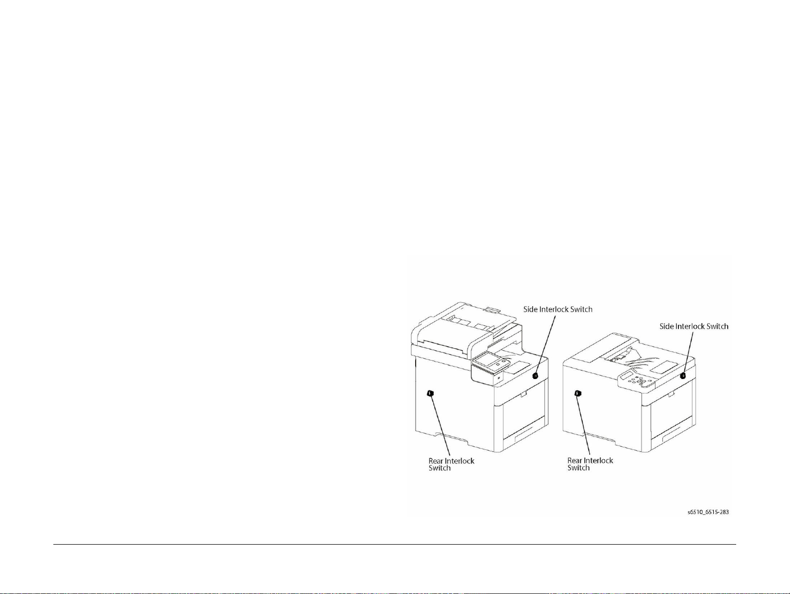
Safety Interlocks
Use caution so that the safety devices for preventing accidents (interlocks switches, fuses,
thermostats, etc.) and the protective parts for users (covers, control panel, etc.) can function as
intended. Make sure all covers are in place and all interlock switches are functioning correctly
after you have completed a service call. If you bypass an interlock switch, use extreme caution
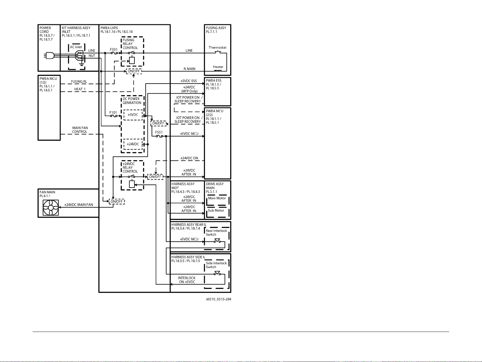
when working on or around the printer. Figure 1 and Figure 2 show the interl ock switch loca
tions and circuitry.
-
Pay attention to these safety guidelines to ensure the continued, safe operation of the printer.
• Use the supplies specifically designed for your system. The use of unsuitable materials
may cause poor performance and a possible safety hazard.
• Follow all warnings and instructions marked on, or supplied with, the system, options and
supplies.
NOTE: The Total Satisfaction Guarantee is available in the United States and Canada. Coverage may vary outside these areas; please contact your local representative for details.
Maintenance Safety
• Do not attempt maintenance not specifically described in the printer documentation.
Revised BUS Update: July 2020
Xerox P6510 Color Printer/WC6515 Color MFP Service Manual
10/2017
Figure 1 Safety Interlock Switch Locations
Introduction
v
Service Safety Summary
Drive Units
When servicing gears or other driving units, be sure to Switch off the machine, switch and
unplug the power cord. Drive them manually when required.
High-Temperature Units
When servicing high-temperature units (securing unit, etc.), be sure to turn them off to prevent
burns, injuries and other troubles. Remove the power plug and wait 40 minutes before starting
service processes so they have cooled down sufficiently.
Routing Wire Harnesses
Before starting the service operation, carefully check how the harness wires are routed. When
routing them, check that they are routed in the same way as they were before the servicing,
and that they are not pinched or do not interfere with the corners or edges of any operating
components.
Battery
A lithium battery is used on the ESS PWB.
WARNING
To avoid the possibility of fire or explosion, always replace the battery with the same
type, and dispose of old batteries as required by local regulations.
Figure 2 Safety System Schematic
Introduction
Service Safety Summary
10/2017
vi
Revised BUS Update: July 2020
Xerox P6510 Color Printer/WC6515 Color MFP Service Manual
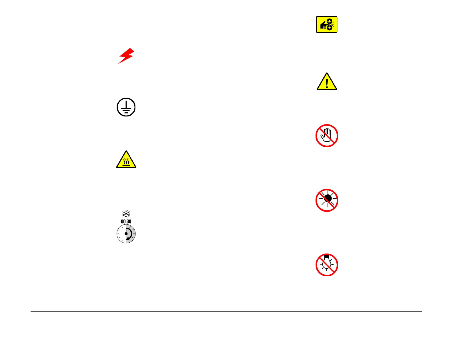
Symbols Used on the Product
The following precautionary symbols may appear on the machine.
Figure 1 indicates Danger High Voltage.
Figure 1 High Voltage symbol
Figure 2 is the Protective Ground (Earth) symbol.
Figure 2 Protective Ground (Earth) symbol
Figure 3 is the symbol indicating a hot surface. Use caution to avoid personal injury.
Figure 3 Hot Surface symbol
Figure 5 Pinch Injury symbol
Figure 6 is the symbol to use caution (or draws attention to a particular component). Refer to
the manual(s) for information.
Figure 6 Use Caution symbol
Figure 7 is the symbol indicating that the item is sensitive and should not be touched.
Figure 7 Do Not Touch symbol
Figure 8 is the symbol indicating the item is sensitive to sunlight, and exposure to it will reduce
its life span.
Figure 4 is the symbol indicating that the surface is hot while the printer is running. After turning
off the power, wait 30 minutes.
Figure 4 Wait 30 Minutes symbol
Figure 5 is the symbol indicating where to avoid pinching fingers in the printer. Use caution to
avoid personal injury.
Revised BUS Update: July 2020
Xerox P6510 Color Printer/WC6515 Color MFP Service Manual
Figure 8 No Sunlight symbol
Figure 9 is the symbol indicating the item is sensitive to any light, and exposure to it will reduce
its life span.
Figure 9 No Light symbol
10/2017
vii
Symbols Used on the Product
Introduction

Volt age Me as ureme n t and S pec if ica t ions
Table 1 shows the voltages present in the WorkCentre 6515. Measurements of DC voltage
must be made with reference to the specified DC Com mon, unless some other point is refer
enced in a diagnostic procedure. All measurements of AC voltage should be made with respect
to the adjacent return or ACN wire.
Table 1 Voltage Measurement and Specifications
Voltage Specification
Input Power 220V 198VAC to 254VAC
Input Power 100V 90VAC to 135VAC
Input Power 120V 90VAC to 135VAC
+5VDC +4.75VDC to +5.25VDC
+24VDC +23.37VDC to +27.06VDC
Logic Voltage Levels
Table 2 show the logic levels present in the WorkCentre 6515. Measurements of logic levels
must be made with reference to the specified DC Com mon, unless some other point is refer
enced in a diagnostic procedure.
Health and Safety Incident Reporting
I. Summary
-
This section defines requirements for notification of health and safety incidents involving Xerox
products (equipment and materials) at customer locations.
II. Scope
Xerox Corporation and subsidiaries worldwide.
III. Objective
To enable prompt resolution of health and safety incidents involving Xerox products and to
ensure Xerox regulatory compliance.
IV. Definitions
Incident:
An event or condition occurring in a customer acco unt that has resulted in injury, illness or
property damage. Examples of incidents include machine fires, smoke generation, physical
-
injury to an operator or service representative. Alleged events and product conditions are
included in this definition.
Table 2 Logic Levels
Voltage H/L Specification
+5VDC H = +3.00VDC or greater
L = below 0 .8VDC
+3.3VDC H = +2VDC or greater
L =below 0.8VDC
DC Voltage Measurement in RAPs
The RAPs have been designed so that when it is required to use the DMM to measure a DC
voltage, the first test point listed is the location for the red (+) meter lead and the second test
point is the location for the black meter lead. For example, the following statement may be
found in a RAP.
There is +5VDC from P/J7 to P/J68.
In this example, the red meter lead would be placed on P/J7 and the black lead on P/J68.
If a second test point is not given, it is assumed that the black meter lead may be attached to
chassis ground.
V. Requirements
Initial Report:
1. Xerox organizations shall establish a process for individuals to report product incidents to
Xerox Environment Health & Safety within 24 hours of becoming aware of the event.
2. The information to be provided at the time of reporting is contained in Appendix A (Health
and Safety Incident Report involving a Xerox product).
3. The initial notification may be made by any of the following methods:
• Email Xerox EH&S at: usa.product.incident@xerox.com.
• Fax Xerox EH&S at: 585-422-2249.
NOTE: If sending a FAX, please also send the original via internal mail.
Responsibilities for resolution:
1. Business Groups/Product Design Teams responsible for the product involved in the incident shall:
a. Manage field bulletins, customer correspondence, product recalls, safety retrofits.
b. Fund all field retrofits.
2. Field Service Operations shall:
a. Preserve the Xerox product involved and the scene of the incident inclusive of any
associated equipment located in the vicinity of the incident.
b. Return any affected equipment/part(s) to the location designated by Xerox EH&S
and/or the Business Division.
c. Implement all safety retrofits.
3. Xerox EH&S shall:
a. Manage and report all incident investigation activities.
b. Review and approve proposed product corrective actions and retrofits, if necessary.
c. Manage all communications and correspondence with government agencies.
Introduction
Voltage Measurement and Spec ifications, Health and
10/2017
viii
Revised BUS Update: July 2020
Xerox P6510 Color Printer/WC6515 Color MFP Service Manual

d. Define actions to correct confirmed incidents.
VI. Appendices
The Health and Safety Incident Report involving a Xerox Product (Form # E H &S -700) is available in the location that follows:
• GSN Library 1789
Regulatory Specifications
Xerox has tested this product to elec tromagnetic emission and immunity standards. These
standards are designed to mitigate interference caused or receiv ed by this product in a typical
office environment.
United States (FCC Regulations)
The WorkCentre 6515 has been tested and found to comply with the limits for a Class A digital
device pursuant to Part 15 of the FCC Rules. These limits are designed to provide reasonable
protection against harmful interference in a commercial installation. This equipment generates,
uses, and can radiate radio frequency energy. If it is not installed and used in accordance with
these instructions, it may cause harmful interference to radio communications. Operation of
Class A equipment in a residential area is likely to cause harmful interference in which case the
user will be required to correct the interference at his/her own expense. There is no guarantee
that interference will not occur in a particular installation.
If this equipment does cause harmful interference to radio or television reception, which can be
determined by turning the equipment Off and O n, the user is encou raged to try to correct the
interference by one or more of the following measures:
• Reorient or relocate the receiver.
• Increase the separation between the equipment and receiver.
• Connect the equipment to a different electrical circuit.
• Consult the dealer or an experienced radio/ television technician for help.
Any modifications not expressly approved by Xerox could void the user's authority to operate
the equipment. To ensure compliance with Part 15 of the FCC rules, use shielded interf ace
cables.
Canada (Regulations)
This Class A digital apparatus complies with Canadian ICES-003.
Revised BUS Update: July 2020
Xerox P6510 Color Printer/WC6515 Color MFP Service Manual
Cet appareil numérique de la classe A est conforme à la norme NMB-003 du Canada.
European Union
CE Mark
The CE mark (Figure 1) applied to this product symbolizes
Xerox’s declaration of conformity with the following applica
Figure 1 CE Symbol
February 26, 2014, Low Voltage Directive 2014/35/EU
April 20, 2014, Electromagnetic Compatibility Directive 2014/30/EU
This product, if used properly in accordance with the user's instructions, is neither dangerous
for the consumer nor for the environment.
10/2017
ix
Health and Safety Incident Reporting, Regulatory
ble Directives of the European Union as of the dates indicated:
-
Introduction

To ensure compliance with European Union regulations, use shielded interface cables.
A signed copy of the Declaration of Conformity for this product can be obtained from Xerox.
Translation of Warnings
WARNING
Take care, a hazardous voltage is present at the C inlet, LVPS PWB (PL 18.1 Item 16/PL
18.5 Item 16), and ESS MF P/ESS SFP P WBs (PL 18.1 Item 5/PL 18.5 Item 5 ). Electricity
can cause death or injury.
DANGER: Faire attention, une tension électrique dangereuse est présente au niveau de
la sortie de l'inverseur de la lampe d'exposition.
AVVERTENZA: fare attenzione alla carica elettrica di uscita dell'invertitore della lampada
di esposizione. L'el e ttricità può causare infor tuni o morte.
VORSICHT: Achtung: Spannung am Ausgang des Belichtungslampeninverters.
AVISO: Tenga cuidado; hay tensión peligrosa en la salida del inversor de la lámpara de
exposición. La electricidad puede causar lesiones e incluso la muerte.
WARNING
Isolate the machine from the electrical supply whi le performing tasks that do not need
electricity. Refer to GP 4. Electricity can cause death or injury. Moving parts can cause
injury.
DANGER: Isolez la machine de l’alimentation électrique lorsque vous effectuez des
tâches ne nécessitant pas l’électricité. Reportez-vous à GP 4. L’électricité peut être à
l’origine de blessures, voire d’un accident mortel. Les pièces amovibles peuvent être à
l’origine de blessures.
AVVERTENZA: Isolare la macchina dall’alimentazione elettrica quando si eseguono
attività che non richiedono elettricità. Vedere GP 4. L’elettricità può causare morte o
lesioni personali. Le parti in movimento possono causare lesioni personali.
VORSICHT: Gerät bei Arbeiten, die keinen Strom erfordern, von der Stromversorgung
trennen. Andernfalls besteht Stromschlaggefahr und Verletzungsgefahr durch bew egli
che Teile. Siehe auch GP 4.
AVISO: Mantenga la máquina aislada de la energía eléctrica mientras realiza tareas que
no necesitan electricidad. Consulte GP 4. La electricidad puede causar lesiones e
incluso la muerte. Las partes móviles pueden causar daños.
-
Introduction
Regulatory Specifications, Translation of Warnings
10/2017
x
Revised BUS Update: July 2020
Xerox P6510 Color Printer/WC6515 Color MFP Service Manual

WARNING
Switch off the electricity to the machine. Refer to GP 4. Disconnect the power cord from
the customer supply while performing tasks that do not need electricity. Electricity can
cause death or injury. Moving parts can cause injury.
DANGER: Mettez la machine hors tension. Reportez-vous à GP 4. Déconnectez le cordon d'alimentation de l'alimentation du client lorsque vous réalisez des tâches qui ne
nécessitent pas d'électricité. L'électricité peut être à l'origine de blessures, voire d'un
accident mortel. Les pièces amovibles peuvent être à l'origine de blessures.
AVVERTENZA: Spegnere la macchina. Vedere GP 4. Scollegare il cavo di alimentazione
dall'alimentatore quando si eseguono attività che non richiedono elettricità. L'elettricità
può causare morte o lesioni personali. Le parti in movimento possono causare lesioni
personali.
VORSICHT: Schalten Sie die Stromversorgung der Maschine ab. Siehe auch GP 4. Zie hen Sie das Stromkabel ab, wenn Sie Aufg aben ausführen, für die keine Stromversorgung benötigt wird. Stromschläge können Todesfällen oder Verletzungen verursachen.
Bewegliche Teile können zu Verletzungen führen.
AVISO: Apague la electricidad de la máquina. Consulte el GP 4. Desconecte el cable de
alimentación eléctrica de la toma de pared mientras esté realizando tareas que no
necesiten corriente. La electricidad puede causar daños o la muerte. Las partes móviles
pueden causar daños.
WARNING
Do not work in a confined space. 1 m (39 inches) space is needed for safe working.
DANGER: Ne pas travailler dans un espace restreint. 1 mètre d'espace est nécessaire
pour un dépannage en tout e s é cu r ité.
AVVERTENZA: Non lavorare in uno spazio limitato; è necessario uno spazio di almeno
un metro attorno alla macchina per la sicurezza dell'operatore.
VORSICHT: Nur mit ausreichendem Bewegungsspielraum (1 m) arbeiten.
AVISO: No trabaje en un espacio reducido. Se necesita 1 metro de espacio para trabajar
con seguridad.
WARNING
Perform the steps in the following procedure carefully. Failure to follow this procedure
carefully could result in electrical shock and personal injury.
DANGER: Faire très attention en effectuant les étapes de la procédure suivante. Si cette
procédure n'est pas strictement respectée, il y a des risques d'électrocution et d'autres
blessures.
AVVERTENZA: Si prega eseguire attentamente la seguente procedura. Omettere di
eseguire attentamente la procedura indicata può provocare forti scosse e gravi ferite.
VORSICHT: Befolgen Sie die Schritte der folgenden Anleitung genau. Die Nichtbefolgung dieser Anweisungen kann elektrischen Schlag oder andere Körperverletzungen
zur Folge haben.
AVISO: Lleve a cabo los pasos del procedimiento siguiente con mucho cuidado. No
seguir este procedimiento cuidadosamente puede ocasionar una descarga el éctrica y
lesiones personales
WARNING
Use extreme care when working in the following area. Some of the components are electrically energized and could cause electrical shock and personal injury if touched.
DANGER: Faire très attention en travaillant dans la zone suivante. Certains éléments
portent une charge électrique et présentent un risque d 'électrocution et de graves b les
sures s'ils sont touchés.
AVVERTENZA: Maneggiare la seguente area con la massima precauzione. Alcuni componenti sono carici di corrente elettrica e se toccati possono provocare scosse
elettriche e lesioni.
VORSICHT: Bei Arbeiten in folgenden Bereichen besondere Vorsicht walten lassen.
Einige der Komponenten sind elektrisch aufgeladen und können bei Berührung einen
Stromschlag und körperliche Verletzung verursachen
AVISO: Tenga mucho cuidado al trabajar en el área siguiente. Algunos de los componentes están cargados eléctricamente y podrían producir descarga s y lesiones, si se
tocan
-
WARNING
Use high voltage probes when testing high voltage. Electricity can cause death or injury.
DANGER: Utilisez des sondes haute tension lorsque vous testez les hautes tensions.
L'électricité peut être à l'origine de blessures, voire d'un accident mortel.
AVVERTENZA: Quando si esegue il test della tensione ad alto voltaggio, utilizzare pun-
tali appropriati. L'elettricità può causare morte o lesioni personali.
VORSICHT: Verwenden Sie ein Hochspannungsmessgerät zur Prüfung von Hochspan-
nung. Stromschläge können Todesfällen oder Verletzungen verursachen.
AVISO: Utilice sondas preparadas para alto voltaje cuando esté comprobando puntos
de alto voltaje. La electricidad puede causar daños o la muerte.
Revised BUS Update: July 2020
Xerox P6510 Color Printer/WC6515 Color MFP Service Manual
10/2017
WARNING
Do not work in a confined space. 1 m (39 inches) space is needed for safe working.
DANGER: Ne pas travailler dans un espace restreint. 1 mètre d'espace est nécessaire
pour un dépannage en toute sécurité.
AVVERTENZA: Non lavorare in uno spazio limitato; è necessario uno spazio di almeno
un metro attorno alla macch ina per la sicurezza dell'operatore.
VORSICHT: Nur mit ausreichendem Bewegungsspielraum (1 m) arbeiten.
AVISO: No trabaje en un espacio reducido. Se necesita 1 metro de espacio para trabajar
con seguridad.
Introduction
xi
Translation of Warnings

WARNING
Use safe handling procedures when removing the module. Refer to GP 16. The module
is heavy.
DANGER: Conformez-vous aux procédures de manipulation de sécurité pour le retrait
du module. Reportez-vous à GP 16. Le module est lourd.
AVVERTENZA: Utilizzare procedure di gestione sicure durante la rimozione del modulo.
Vedere GP 16. Il modulo è pesante.
VORSICHT: Verwenden Sie sichere Vorgehensweisen zum Entfernen des Moduls. Siehe
auch GP 16. Das Modul ist sehr schwer.
AVISO: Utilice los procedimientos de seguridad cuando elimine el módulo. Consulte el
GP 16. El módulo es pesado.
WARNING
Follow the service procedure exactly as written. Use of controls or adjustments other
than those specified in this manual, may result in an exposure to invisible laser radia
tion. During servicing, the invisible laser radiation can cause eye damage if looked at
directly.
DANGER: Les procédures de dépannage doivent être suivies à la lettre. Si les réglages
ou vérifications ne sont pas effectués suivant les instructions de ce manuel, il peut y
avoir un risque d'exposition dangereuse au faisceau laser. Celui-ci peut provoquer des
lésions oculaires s'il est observé directement.
AVVERTENZA: Eseguire le procedure di servizio esattamente come descritto. L'utilizzo
di dispositivi di controllo o di registrazione diversi da quelli riportati in questo manuale
potrebbe comportare un'esposizione a radiazioni laser invisibili. Tali radiazioni possono
danneggiare gli occhi se si guarda direttamente il fascio laser durante gli interventi di
servizio.
VORSICHT: Die Wartungsarbeiten genau den Anweisungen entsprechend durchführen.
Der Umgang mit Steuer- oder Bedienelementen, deren Verwendung nicht ausdrücklich
in diesem Handbuch angewiesen wurde, kann dazu führen, dass unsichtbare Laser
strahlung frei gesetzt wird. Direkter Blickkontakt mit dem Laserstrahl kann bleibende
Augenschäden verursachen.
AVISO: Siga los procedimientos de mantenimiento tal como están descritos. El uso de
controles o ajustes no especificados en este manual puede tener como resultado la
exposición a radiación láser invisible. Durante las operaciones de mantenimiento, la
radiación de láser invisible puede causar daños en los ojos si se mira directamente a
ella.
WARNING
USA and Canada. Do not install this machine in a hallway or exit route that does not
have 1.12 m (44 inches) of space additional to the normal space requirements in front of
the machine. To conform with fire regulations this additional 1.12 m (44 inches) of space
is needed in front of the machine in hallway and exit routes.
DANGER: États-Unis et Canada. Si cette machine est installée dans un couloir ou une
voie de sortie, 1,12 m (44 pouces) d'espace supplémentaire à l'espace normal doit être
disponible devant la machine conformément aux normes de sécurité d'incendie.
AVVERTENZA: N/A
VORSICHT: N/A
AVISO: Estado s Unidos y Canadá. No instale esta máquina en un corredor o ruta de sal-
ida que no tenga 1.12 m (44 pulgadas) de ancho delante de la máquina, sin incluir el
espacio que ocupe la máquina. Este espacio adicional de 1.12 m (44 pulgadas) delante
de la máquina en corredores y rutas de salida es necesario para cumplir los requisitos
de las normas sobre incendios.
-
WARNING
Use only Xerox materials and components. This product is safety certified using Xerox
materials and components. The use of non Xerox materials and components may invali
date the safety certificate.
DANGER: N'utilisez que des matières premières et des composants Xerox. La sécurité
du produit est assurée dans le cadre de son utilisation avec des matières premières et
des composants Xerox. L'utilisation de matières premières et de composants autres
que ceux de Xerox risque d'invalider le certificat de sécurité.
AVVERTENZA: Utilizzare solo materiali e componenti Xerox per avvalersi della certificazione di protezione. L'utilizzo di materiali e componenti non Xerox può rendere nulla la
certificazione di protezione.
VORSICHT: Verwenden Sie nur Materialien und Komponenten von Xerox. Dieses
-
Produkt besitzt die Sicherheitszertifizierung bei Verwendung von Xerox-Materialien und
-Komponenten. Die Verwendung von Materialien und Komponenten anderer Hersteller
setzt möglicherweise das Sicherheitszertifikat außer Kraft.
AVISO: Utilice solo los materiales y componentes Xerox. Este producto dispone de un
certificado de seguridad si se utilizan los materiales y componentes Xerox. Este certifi
cado de seguridad no será válido si se utilizan materiales y componentes que no sean
de Xerox.
-
-
Introduction
Translation of Warnings
WARNING
Do not touch the Fuser while it is hot.
DANGER: Ne pas toucher au four pendant qu'il est encore chaud.
AVVERTENZA: Non toccare il fonditore quando è caldo.
VORSICHT: Fixierbereich erst berühren, wenn dieser abgekühlt ist.
AVISO: No toque el fusor mientras está caliente.
10/2017
xii
Xerox P6510 Color Printer/WC6515 Color MFP Service Manual
Revised BUS Update: July 2020

WARNING
Do not handle the Fuser components until they have cooled. Some Fuser components
operate at hot temperatures and can produce serious personal injury if touched.
DANGER: Ne pas manipuler les éléments du four avant de les laisser refroidir. Certains
éléments du four fonctionnent à des températures très élevées et peuvent causer de
graves blessures s'ils sont touchés.
AVVERTENZA: Non maneggiare i componenti del fusore finché non sono raffreddati.
Alcuni di questi componenti funzionano ad alte temperature e possono provocare gravi
ferite se vengono toccati.
VORSICHT: Die Fixieranlage sollte erst gehandhabt werden, wenn diese genügend
abgekühlt ist. Einige Teile der Fixieranlage erzeugen übermäßige Hitze und führen bei
der Berührung zu schweren Verbrennungen.
AVISO: No manipule los componentes del fusor antes de que se enfrí e n. Algunos de los
componentes del fusor funcionan a altas temperaturas y pueden ocasionar daños per
sonales graves si se los toca.
WARNING
Do not attempt to remove or lift the following component with less than 2 people. The
component is very heavy and requires at least 2 people to lift or remove it. Any attempt
to remove or lift the component with less than 2 people could result in serious personal
injury.
DANGER: Ne pas tenter d'enlever ou soulever l'élément suivant tout seul. Cet élément
est très lourd; au moins 2 personnes doivent être prése ntes pour le soulèvement ou la
dépose. Toute tentative d'enlever ou soulever cet élément sans la collaboration d'au
moins 2 personnes peut causer de graves blessures.
AVVERTENZA: Non tentare di togliere o sollevare il componente seguente con meno di
2 persone. Il componente è molto pesante e richiede almeno 2 persone per sollevarlo o
rimuoverlo. Tentare di rimuovere o sollevare questo componente con meno di 2 persone
può provocare gravi fer ite.
VORSICHT: Versuchen Sie keinesfalls, die folgende Komponente mit weniger als 2 Personen zu entfernen oder zu heben. Die Komponente ist sehr schwer, daher werden
mindestens 2 Personen benötigt, um sie zu heben oder zu entfernen. Der Versuch, die
Komponente mit weniger als 2 Personen zu entfernen oder zu heben, kann schwere Kör
perverletzung zur Folge habe n.
AV IS O: No intente levantar o retirar el componente siguiente usando menos de 2 personas. El componente es muy pesado, y se necesitan por lo menos 2 personas para levantarlo o retirarlo. Intentar retirar o levantar el componente usando menos de 2 personas
puede resultar en lesionales personales serias.
Technical Support Information
The Xerox Service Manual is the primary document used for repairing, maintaining, and troubleshooting the Phaser 6510 and WorkCentre 6515. To ensure complete understanding of
these products, participation in Xerox Service Training is strongly recommended. To service
these products, certification for these products is required.
For updates to the Service Manual, Service Bulletins, knowledge base, etc., go to:
• Xerox Global Service Net - https://www.xrxgsn.com/secure/main.
For further technical support, contact your assigned Xerox Technical Support representative.
-
-
Revised BUS Update: July 2020
Xerox P6510 Color Printer/WC6515 Color MFP Service Manual
10/2017
xiii
Introduction
Translation of Warnings,

Introduction
Translation of Warnings,
10/2017
xiv
Revised BUS Update: July 2020
Xerox P6510 Color Printer/WC6515 Color MFP Service Manual

SCP 1 Initial Actions........................................................................................................ 1-3
SCP 2 First Call Actions.................................................................................................. 1-4
SCP 3 Normal Call Actions............................ ..................................... .......................... .. 1-4
SCP 4 Fault Analysis ...................................................................................................... 1-5
SCP 5 Subsystem Maintenance ..................................................................................... 1-6
SCP 6 Final Actions........................................................................................................ 1-9
1 Service Call Proced ur es
Revised BUS Update: July 2020
Xerox P6510 Color Printer/WC6515 Color MFP Service Manual
10/2017
1-1
Service Call Procedures

Service Call Procedures
10/2017
1-2
Revised BUS Update: July 2020
Xerox P6510 Color Printer/WC6515 Color MFP Service Manual

SCP 1 Initial Actions
Initial Actions are used to gather information on printer performance
Start a service call with SCP 1 and end with SCP 6 Final Actions.
Also refer to Machine Specifications, GP 7.
Procedure
WARNING
solate the machine from the electrical supply while performing tasks that do not need
electricity. Refer to GP 4. Electricity can cause death or injury. Moving parts can cause
injury.
WARNING
Do not work in a confined space. 1 m (39 inches) space is needed for safe working.
NOTE: Ignore references to options not installed on the printer.
1. Identify the problem.
• Verify the reported problem does exist.
• Ask the operator to describe or demonstrate the problem.
• Print normal customer prints and service test prints.
• Make note of any print-quality problems in the test prints.
• Print a Usage Profile, if the printer is able to print.
2. Make note of any mechanical or electrical abnormalities present.
3. Make note of any unusual noise or smell coming from the printer.
4. To view engine error and jam histories, perform Diagnostic s dC118, dC120, dC122, and
dC125.
5. Take note of symptoms or error messages.
6. Make su re:
a. The power cord is connected to the wall outlet and to the machine.
b. The AC input from the wall outlet is within specifications.
c. Paper is loaded correctly and all paper trays and covers are closed
d. If installed, the USB cable or network connection is installed correctly.
7. If available, check the service log book for any previous actions that may be relevant to
the call.
8. If this is the f irst service call to th is printer, perform SCP 2 First Call Actions, otherwise go
to SCP 3 Normal Call Actions.
Accessing Engine Fault History
Listed below are three ways in which you can access fault history. Additional fault history information appears in GP 2.
3. If the printer is connected to a network and has a TCP/IP address, view the printer’s web
page using a web browser.
a. Open a web browser.
b. Enter the printer’s IP address as the URL.
c. Select > > and the fault history displays.
NOTE: Error and fault code definitions appear in Section 2.
1. Read (if possible) fault history from Device -> Support -> Support Pages -> Err or Histor y
Report on the control panel. The error history is listed on screen.
2. Accessing fault history in Service Diagnostics
Revised BUS Update: July 2020
Xerox P6510 Color Printer/WC6515 Color MFP Service Manual
10/2017
1-3
Service Call Procedures
SCP 1

SCP 2 First Call Actions
First Call Actions are used for the first service call.
SCP 3 Normal Call Actions
Normal Call Actions are used to determine the reason for the service call.
Procedure
1. Check the machine configuration with the customer, refer to Machine Specifications, GP
7. Check that all required hardware and software is installed and/or enabled.
2. Check that all the relevant machine settings are correctly entered, refer to GP 4 System
Administration T ools.
3. If a fault is present, go to SCP 3 Normal Call Actions. If there is no fault present, go to
SCP 6 Final Actions.
4. Enter the printer and customer details in the service log.
Procedure
NOTE: If a fault message appears at any time. Refer directly to the RAP for the fault mes sage
and perform the procedure.
If possible, perform the following:
1. Review any defective print samples.
2. Determine that the user accessible settings are correct. If necessary refer to the user documentation.
3. Check all job queues and verify with the customer any requirement to print the documents
in memory, before switching off the power or clearing memory.
4. Print the Customer Assistance Report (Call for Assistance), then record the total print
count.
5. Go to SCP 4 Fault Analysis.
Service Call Procedures
SCP 2, SCP 3
10/2017
1-4
Revised BUS Update: July 2020
Xerox P6510 Color Printer/WC6515 Color MFP Service Manual

SCP 4 Fault Analysis
Fault Analysis is used to identify a fault.
Procedure
When diagnosing or repairing a fault in a particular subsystem, exercise the machine in all
modes until the fault is determined. In the instance of finding more than one fault or failure, cor
rect one fault before going to the next fault. If no fault is found, go to SCP 5 Subsystem Maintenance.
Fault Codes
If a fault code is displayed, go to the relevant RAP. Also refer to Unresolved Faults.
Control Panel Faults
If the power is on but the Control Panel is blank, test the Control Panel with dc305.
Image Quality Defects
If the image quality is defective, go to the IQ1 Image Quality Entry RAP.
Unresolved Faults
If a fault cannot be resolved using the appropriate RAP, and only if instructed by 2nd level support, obtain a device log. Refer to GP 38 Obtaining Audit and Device Logs. Escalate the problem to 2nd level support.
Additional Information
If necessary, refer to the following general procedures and information:
• GP 1 Using the Service Diagnostics
• GP 2 Fault Codes and History Logs
• GP 3 Device In formation
• GP 4 How to Switch Off or Sw i t c h On the Printer
• GP 6 Electrostatic Discharge Prevention
• GP 7 Machine Specifications
• GP 8 General Disassembly Precautions
• GP 9 Firmware Version Upgrade
• GP 10 How to Check a Motor
• GP 11 How to Check a Sensor
• GP 12 How to Check a Solenoid or Clutch
• GP 13 How to Check a Switch
• GP 14 How to Clone Device Settings
• GP 15 Special Boot Modes
• GP 16 Separate System Modules
• GP 17 External FAX Line Test
• GP 18 Printing Reports
• GP 19 Intermittent or Noise Problem
• GP 20 How to Safely Lift or Move the Printer
• GP 21 Machine Lubrication
• GP 22 Installation Space Requirements
• GP 23 First Print Output Time
• GP 24 Restriction of Hazardous Substances (RoHS)
• GP 26 Media Specifications
• GP 27 Environmental Data
-
• GP 28 Supplies Plan Conversion
• GP 29 How to Check a Dispenser Motor
• GP 30 IP (ESS) Specifications
• GP 31 IIT Specifications
• GP 32 FAX Specifications
• GP 33 Interior and Exterior Cleaning
• GP 34 Cleaning the Scanner and DADF
• GP 35 Setting Up an Ethernet Connection
• GP 36 How to Manually Configure an IP Address
• GP 37 Reset Administrato r Password
• GP 38 Obtaining Audit and Device Logs
• GP 39 FFC Cables
Revised BUS Update: July 2020
Xerox P6510 Color Printer/WC6515 Color MFP Service Manual
10/2017
1-5
Service Call Procedures
SCP 4
SCP 5 Subsystem Maintenance
Subsystem Maintenance contains information regarding the component life of the machine.
Procedure
WARNING
Isolate the machine from the electrical supply w hile performing tasks that do not need
electricity. Refer to GP 4. Electricity can cause death or injury. Moving parts can cause
injury.
1. Clean the Pick Rollers on every call.
2. Use the Control Panel to check maintenance item counters.
3. Compare the counter values to those listed in Table 1.
4. Advise the customer of any routine maintenance items that are approaching or over the
service limit.
Inspection
Lubrication
CAUTION
Plastic parts deteriorate when unspecified lubricants or chemicals are used. To avoid damage,
use only approved lubricant.
The printer is lubricated during assembly at the factory and does not require periodic lubrication. Some parts require lubrication following replacement. These parts are identified in the
replacement procedures. When lubricating during replacement, use approved grease.
Component Life
The design life of the major components are shown in Table 1. Environmental conditions and
actual use will vary these factors. The component life shown in Table 1 is for reference only.
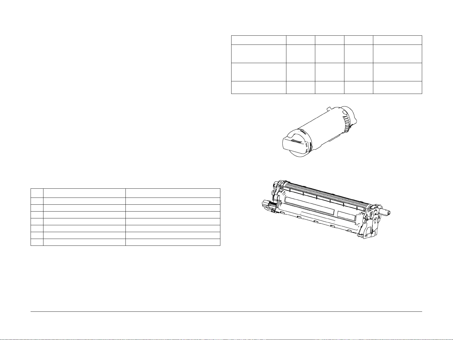
Dimensions and Mass of Consumables
The WC6515 and P6510 contain the consumables shown in Table 1:
Table 2 Dimensions and Mass of Consumables
Consumable Width (mm) Depth (mm) Height (mm) Mass (g)
Toner Cartridges C, M, Y,
K
(Figure 1)
Drum Cartridges C, M, Y,
K
(Figure 2)
Waste Cartridge
(Figure 3)
61.3 180 57.3 K: 100/120/140
C,M,Y: 90/110/120
(STD / HI / EX-HI)
77.3 335.4 78.5 720
357 176.3 33 250
Figure 1 Toner Cartridge
Table 1 Design Life of Major Components
1. Pick and Nudger Rollers 100,000 pages
2. Separator Roller 100,000 pages
3. Transfer Unit / Transfer Roller 100,000 images
4. Fuser 100,000 images
5. Feed Rollers 100,000 pages
6. Waste Cartridge 3 0,000 pages
7. Drum Cartridge 48,000 pages
Consumables and Maintenance
Consumables consist of C, M, Y, and K Toner Cartridges, C, M, Y , and K Drum Cartridges, and
the Waste Cartridge.
Service Call Procedures
SCP 5
10/2017
1-6
Figure 2 Drum Cartridge
Revised BUS Update: July 2020
Xerox P6510 Color Printer/WC6515 Color MFP Service Manual
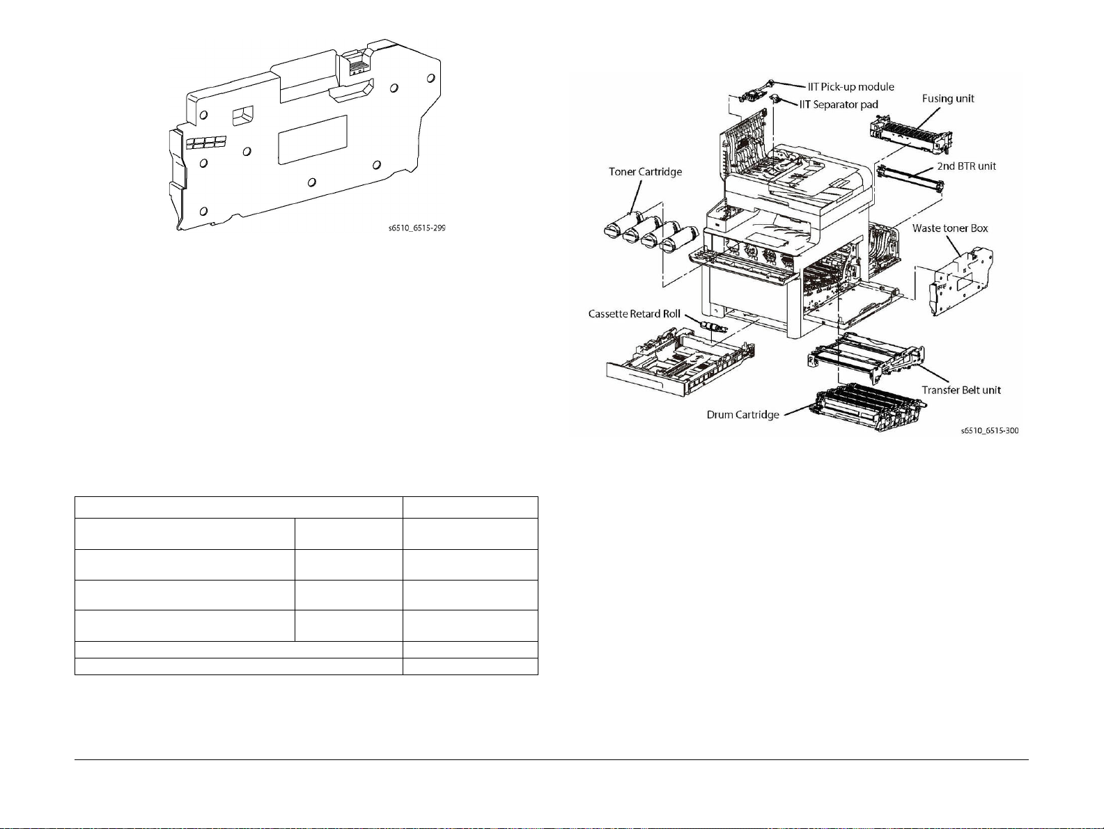
Figure 3 Waste Cartridge
Consumables Life Expectancies
Each Toner Cartridge (except s tarter cartridges) has a CRUM (Customer Replaceable Unit
Monitor) to record regional and toner usage information. The CRUM maintains a count of the
amount of toner consumed. When the count reaches set values, warning and error messages
appear to notify the user when near and end of life status is reached.
Like the Toner Cartridges, each Drum Cartridge has a CR UM to maintain a page count. When
the count reaches a set value, warning and error m essages a ppear to notify the user that the
Drum Cartridge has reached near or end of life status.
NOTE: The specifications showing life ratings are correct at the time of product release. For
the most current values, go to www.xerox.com.
Life ratings are shown in Table 3.
• Transfer Belt unit + Transfer Roller unit: 100 kPV (life of machine)
• DADF Feed Rollers: 100 kPV (WorkCentre WC6515 only) (life of machine)
Figure 4 WC6515 Routine Maintenance Items
Table 3 Life Expectancies for Consumables
Consumable Capacity
CMYK Standard Capacity Toner Cartridges starter cartridges color: 1,000
black: 1,500
sold cartridges color: 1,000
CMYK High Capacity/Extra High Capacity
Toner Cartridges
Drum Cartridge (C, M, Y, K) 48,000
Waste Cartridge 30,000
Routine Maintenance Items
Figure 4 and Figure 5 show the routine maintenance items which are service parts:
• Fuser (110V / 220V): 100 kPV (life of machine)
Revised BUS Update: July 2020
Xerox P6510 Color Printer/WC6515 Color MFP Service Manual
sold cartridges color: 2,500 / 4,500
metered cartridges color: 2,500
black: 2,500
black: 6,000 / N/A
black: 6,000
10/2017
1-7
Service Call Procedures
SCP 5
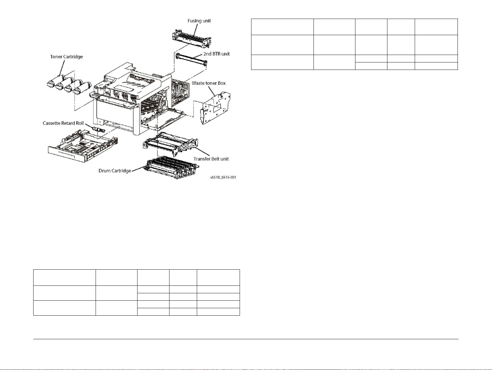
Figure 5 P6510 Routine Maintenance Items
Table 4 Hardware Kit P6510 and WC6515
Type Shape PL Number Size
Screw for sheet metal
Silver, with washer and
plane washer
E-ring E2 D4 354W027278 (2)
SM20 M3x8mm 112W27898 (2)
E6 D6 354W024278 (2)
Part Number
(Quantity)
Hardware Kit
The spare parts available for repairs and maintenance includes a hardware kit. The kit contains
miscellaneous screws and e-clips that can be used to replace hardware that is lost or dam
aged, Table 4.
Since the P6510 and WC6515 use various types of hardware (screws, E-clips), ensure that the
correct hardware is used when installing parts. Use special caution not to confuse the screws
used for plastic with those used for sheet metal. Using the wrong type of screw ma y result in
damage to the screw threads or other problems.
Table 4 Hardware Kit P6510 and WC6515
Part Number
Type Shape PL Number Size
Screw for plastic
Silver, tapping
Screw for sheet metal
Silver
Service Call Procedures
ST20 M3x8mm 115W27878 (10)
ST21 M3x6mm 826E49690 (2)
SM3 M4x6mm 1 13W35688 (5)
SM18 M3x6mm 116W27678 (10)
(Quantity)
10/2017
SCP 5
-
Revised BUS Update: July 2020
1-8
Xerox P6510 Color Printer/WC6515 Color MFP Service Manual

SCP 6 Final Actions
Final Actions are used to evaluate the total operation of the system and to identif y the actions
required to complete the service call.
Procedure
Complete the following, if a fault is identified, return to SCP 4 Fault Analysis:
1. Perform the end of call subsystem maintenance actions, SCP 5 Subsystem Maintenance.
2. Exercise the machine in all modes, printing from all trays. If a fault message is disp layed
or some other problem is evident, go to SCP 4 Fault Analysis.
3. Make a print of a customer document.
4. If any of the customers selections were changed, return t hem to the cus tomers preferred
settings. Refer to GP 4 System Administration Tools.
5. At the first service and at any subsequent service where changes are made or options are
added, print the configuration report and store it with machine log book. Discard any pre
vious versions of the configuration report.
6. Remove and destroy any copies of test patterns.
7. Ensure the machine and service area are clean before leaving the customer premises.
8. Provide customer training if required.
-
Revised BUS Update: July 2020
Xerox P6510 Color Printer/WC6515 Color MFP Service Manual
10/2017
1-9
Service Call Procedures
SCP 6

Service Call Procedures
SCP 6
10/2017
1-10
Revised BUS Update: July 2020
Xerox P6510 Color Printer/WC6515 Color MFP Service Manual

2 Status Indicator RAPs
Troubleshooting Overview
Troubleshooting Overview .............................................................................................. 2-9
Chain 001 - 005
1DC +5VDC Power Fault RAP........................................................................................ 2-13
1AC +24VDC Power Fault RAP................................................ ......................... ............. 2-13
002-500 UI Error RAP..................................................................................................... 2-14
003-311 IIT CDI I/F Mismatch....................................................... .... .. ........... .. .... .... ....... 2-14
003-318, 003-319 IIT Software Fail.............................. .. ......... .... .. .... .... ....... .... .. .... .... ..... 2-15
003-320 to 003-343 IISS-ESS Communication Fail........................................................ 2-15
003-344 IISS-ESS X Hotline Fail .................................................................................... 2-16
003-345, 003-346 X PIO Mismatch RAP ................................................................... ..... 2-17
003-700 Returned Documents Error RAP..... .................................................................. 2-17
003-701 Duplication Prevention Code RAP.................................................................... 2-18
003-702 Different Magnification RAP................................................................. .. .. .... ..... 2-18
003-703, 003-704 Color Correction RAP ........................................................................ 2-19
003-705 Energy Saving Paper Size Mismatch RAP ....................................................... 2-19
003-750 Insufficient Documents Duplex Book RAP........................................................ 2-20
003-751 Capacity RAP.................................................................................................... 2-20
003-752, 932, 935 600dpi Cannot be Scanned RAP....................................... .. .... .. .. ..... 2-21
003-753, 913, 930, 933 300dpi Cannot be Scanned RAP.............................................. 2-21
003-754, 003-756 S2X Error RAP................................................................................... 2-22
003-757, 931, 934 400dpi Cannot be Scanned RAP....................................... .. .... .. .. ..... 2-22
003-760, 003-761 Scan Settings Error RAP ................................................................... 2-23
003-763 Adjustment Chart Not Found RAP.................................................................... 2-23
003-764 Document Insufficient (image overlay) RAP ..................................................... 2-24
003-780 Scan Image Compression Error RAP ............................................................... 2-24
003-795 AMS Limit Error RAP ........................................................................................ 2-25
003-940 Insufficient Memory RAP .................................................................................. 2-25
003-941 Insufficient Page Memory RAP......................................................................... 2-26
003-942, 003-956 Document Size Auto Detect RAP...................................................... 2-26
003-944 Repeat Image Count Fail RAP.......................................................................... 2-27
003-946 Image Rotation (Copy APS) RAP ..................................................................... 2-27
003-947, 948 Document Error RAP ................................................................................ 2-28
003-952 Document Color Mismatch RAP ....................................................................... 2-28
003-955 Documents Size Exchange Error RAP ............................................................. 2-29
003-956 Documents Size Unknown Error RAP ......................................................... ..... 2-29
003-963, 965, 966 ATS/APS RAP ......................... .. .. .... .. ....... .. .. .... .. .. ....... .. .... .. .. .... .. ..... 2-30
003-970, 003-976 FAX Line Memory RAP............................................................... ....... 2-30
003-971 Prevention Code Detect With The Right To Cancel RAP................................. 2-31
003-972 Maximum Stored Page RAP............................................................................. 2-31
003-973 Image Rotation RAP ......................................................... .. .... ....... .. .. .. .... .. .. ..... 2-32
003-974 Next Original Specification RAP ....................................................................... 2-32
003-977 Document Mismatch (Multi Scan) RAP. ............................................................ 2-33
003-978 Color Document Mismatch (Multi Scan) RAP................................................... 2-33
005-121, 123, 124, 125, 305, 900, 906, 908, 911, 940 DADF Jam RAP........................ 2-34
005-210, 005-275 DADF Fail RAP........................................................ ....... .. .. .... .. .. .. ..... 2-34
005-500 Write to DADF-ROM Error RAP........................................................................ 2-35
005-941 Not Enough Documents RAP................................................ .... .... .... ......... .... ... 2-35
Chain 010
010-105, 010-106 Fusing Assembly Exit Sensor RAP.................................................... 2-37
010-331, 338, 344 Fusing Assembly HR RAP................................................................ 2-38
Chain 016
016-211, 016-212 SW Option Fail Memory Low RAP..................................................... 2-41
016-214 SW Option Fail (FAX Card) RAP ...................................................................... 2-41
016-234, 016-235 XCP Error RAP .................................................................................. 2-42
016-242 System GMT Clock Fail RAP............................................................................ 2-42
016-244 Self-Signed Certificate Auto Update Fail RAP.................................................. 2-43
016-310 SSMM Job Log Full RAP .................................................................................. 2-43
016-311, 315, 319, 354 Scanner/IIT Errors RAP ............................................................ 2-44
016-320 Document Formatter Fatal Error RAP............................................................... 2-44
016-321 FAX Module Error RAP..................................................................................... 2-45
016-323 B-Formatter Fatal Error RAP............................................................................. 2-45
016-324 Scheduled Image Overwrite RAP ..................................................................... 2-46
016-325 Using Personal Certificate RAP........................................................................ 2-46
016-326, 362, 607 UI Cable Connection Fail RAP....................................................... .. . 2-47
016-328 Connection Fail RAP...................................... .. .... .. .. .. ....... .. .. .... .. .. .... ..... .. .... .. .. . 2-47
016-330 to 016-332 Cont System Memory Fail RAP...................................................... 2-48
016-342 to 016-345 Controller Fail RAP......................................................................... 2-48
016-346 Cont A4FAX Modem Diagnosis Fail RAP......................................................... 2-49
016-349 to 016-351 eMMC Card Errors RAP ................................................................. 2-49
016-352, 609, 610 Internal Network Init/PCI/PCIEX Fail RAP........................................ 2-50
016-353, 356, 606, 608 IOT-Controller Communication Fail RAP .................................. 2-50
016-355, 016-356 Controller ASIC Fail RAP................................................................... 2-51
016-359, 360, 361 Controller USB Fail RAP................................................................... 2-51
016-370 Controller Diagnostic Fail RAP.......................................................................... 2-52
016-371 Controller USB 1.1 Host Fail RAP..................................................................... 2-52
016-383 Controller OS Communication Fail RAP .......................................................... . 2-53
016-400, 401, 402, 403, 406 802.1x Authentication Failure - Network1 RAP................. 2-53
016-404 802.1x Inside Failure RAP ................................................................................ 2-54
016-405 Certificate DB File Error RAP............................................................................ 2-54
016-407 to 016-412 XCP Error RAP.. ............................................................................. 2-55
016-422, 016-423 Offline RAP ....................................... .... .. .... ....... .... .. .... .... .. ....... .... .... . 2-55
016-424, 016-425 Power Mode RAP .............................................................................. 2-56
016-426 Remote Services Error RAP ............................................................................. 2-56
016-427, 428, 429, 430, 431, 432 802.1x Failures (Network 2) RAP.............................. 2-57
016-450 SMB Host Name Duplicated RAP..................................................................... 2-57
016-453, 016-454 IPv6/Dynamic DNS Failure RAP........................................................ 2-58
016-455, 016-456 SNTP Time Out RAP .................................................................... .. ... 2-58
016-461 Under Non-transmitted Image Log Stagnation RAP......................................... 2-59
016-500 ROM Write Error (During DLD Method) RAP.................................................... 2-59
016-503 to 016-505 SMTP Server Fail for Redirector RAP ............................................ 2-60
016-507, 016-508 Image Log Send Fail RAP ................................................................. 2-60
Revised BUS Update: July 2020
Xerox P6510 Color Printer/WC6515 Color MFP Service Manual
10/2017
2-1
Status Indic a tor RAPs

016-509, 016-510 Image Log No Send Rule RAP................................ ....... .. .. .. .... .. .. ..... 2-61
016-511, 016-512 Image Log Invalid Send Rule RAP.................................................... 2-61
016-513 SMTP Server Reception Error RAP.................................................................. 2-62
016-514 XPS Error RAP ................................................................................................. 2-62
016-515 XPS Short of Memory ....................................................................................... 2-63
016-516 XPS Print Ticket Description Error RAP ........................................................... 2-63
016-519 Device DV Limit Reached RAP......................................................................... 2-64
016-522 LDAP SSL Error 112 RAP ................................................................................ 2-64
016-523 LDAP SSL Error 113 RAP ................................................................................ 2-65
016-524, 016-525 LDAP SSL Error 114 and 115 RAP...................................... .... .... ..... 2-65
016-526 LDAP SSL Error 116 RAP ................................................................................ 2-66
016-527 LDAP SSL Error 117 RAP ................................................................................ 2-66
016-529 Remote Download Server Timeout RAP .......................................................... 2-67
016-533 Kerberos Attestation Protocol Error 37 RAP..................................................... 2-67
016-534 Kerberos Attestation Protocol Error 41 and 42 RAP......................................... 2-68
016-535 Remote Download File Access Error RAP........................................................ 2-68
016-536 Host Name Solution Error in Remote Download RAP ...................................... 2-69
016-537 Remote Download Server Connection Error RAP ............................................ 2-69
016-539 Kerberos Attestation Other Protocol Error RAP................................................ 2-70
016-543, 545, 546, 548, 553, 554, 555, 556, 557, 558 Attestation Agent Error RAP ..... 2-70
016-559 Remote Download Parameter Error RAP ......................................................... 2-71
016-560 Attestation Agent Error 560 RAP...................................................................... 2-71
016-562 Detected User Duplication RAP . ....................................................................... 2-72
016-563 ImageLog Memory Full (Exp. Kit) RAP............................................................. 2-72
016-564 Remote Download Server Authentication Failed RAP...................................... 2-73
016-570 Job Ticket Out of Memory RAP ........................................................................ 2-73
016-571 Job Ticket Wrong Parameters RAP.................................................................. 2-74
016-572 Job Ticket Media Error RAP ............................................................................. 2-74
016-573 Job Ticket Parse Error RAP.............................................................................. 2-75
016-574 FTP Host Name Solution Error RAP................................................................. 2-75
016-575 FTP DNS Server Error RAP.............................................................................. 2-76
016-576 FTP Server Connection Error RAP................................................................... 2-76
016-577 FTP Service RAP.............................................................................................. 2-77
016-578 FTP Login Name or Password Error RAP ........................................................ 2-77
016-579 FTP Scanning Picture Preservation Place Error RAP ...................................... 2-78
016-580 FTP File Name Acquisition Failure RAP ............................................ .... .. .. ....... 2-78
016-581 FTP File Name Suffix Limit RAP....................................................................... 2-79
016-582, 016-588 FTP File Creation Failure RAP.......................................................... 2-79
016-583, 016-584 FTP Folder Creation Failure RAP...................................................... 2-80
016-585, 587, 589 FTP File Delete/Read Failure RAP .............................................. ..... 2-80
016-586 FTP Lock Folder Delete Failure RAP................................................................ 2-81
016-590 FTP Data Reading Failure RAP................................................................... ..... 2-81
016-591 FTP Scan Filing Policy RAP ............................................................................. 2-82
016-592 FTP DAT File Access Error RAP ...................................................................... 2-82
016-593 to 016-596 FTP Error RAP................................................................................ 2-83
016-597 Same File on FTP Server RAP.................................................................. ....... 2-83
016-598, 016-599 Email Message Size RAP.................................................................. 2-84
016-600, 016-601 KO Authentication Locked RAP......................................................... 2-84
016-604 Debug Log Created RAP. ................................................................................. 2-85
016-700 Password Below Minimum RAP ....................................................................... 2-85
016-702 Out of Page Buffer RAP.................................................................................... 2-86
016-706 Maximum User Number Exceeded RAP . .......................................................... 2-86
016-711 Email Transmission Size Limit RAP . ................................................................. 2-87
016-712 Panther Capacity RAP...................................................................................... 2-87
016-713, 016-714 Security Box Error RAP ..................................................................... 2-88
016-715 ESCP Form Invalid Password RAP .................................................................. 2-88
016-718 Out of PCL6 Memory RAP................................................................................ 2-89
016-719 Out of PCL Memory RAP.................................................................................. 2-89
016-720 PCL Command Error RAP ................................................................................ 2-90
016-721 Settings Error RAP............................................................................................ 2-90
016-725 B-Formatter Library Image Conversion Error RAP ........................................... 2-91
016-726 PDL Auto Switch Fail RAP................................................................................ 2-91
016-728 Unsupported TIFF Data RAP............................................................................ 2-92
016-729 TIFF Data Size RAP.......................................................................................... 2-92
016-731, 016-732 Invalid Data RAP................................................................................ 2-93
016-733 Destination Address Resolution Error RAP....................................................... 2-93
016-735 Updating Job Template RAP............................................................................. 2-94
016-741 Download Mode Fail RAP................................................................................. 2-94
016-742 Download Data Product ID Mismatch RAP....................................................... 2-95
016-743 Device Model/Panel Type Error RAP ................................................................ 2-95
016-744 Download Data CheckSum Error RAP.............................................................. 2-96
016-745 Download Data XPJL Fatal Error RAP.............................................................. 2-96
016-746, 016-751 Unsupported PDF File RAP............................................................... 2-97
016-747 Drawing Annotation Memory RAP .................................................................... 2-97
016-749 JCL Syntax Error RAP ...................................................................................... 2-98
016-750 Print Job Ticket Description Error RAP............................................................. 2-98
016-752 PDF Short of Memory RAP............................................................................... 2 -99
016-753 PDF Password Mismatched RAP ..................................................................... 2-99
016-755 PDF Print Prohibited RAP................................................................................. 2-100
016-756 to 016-759 Auditron-Prohibit Service RAP........................................................ 2-100
016-760 PS Decompose Failure RAP............................................................................. 2-101
016-761 FIFO Empty RAP .............................................................................................. 2-101
016-762 Print Language Not Installed RAP .................................................................... 2-102
016-763 POP Server Connect RAP ................................................................................ 2-102
016-764 SMTP Server Connect RAP.............................................................................. 2-103
016-765, 016-766 SMTP Server Error RAP.................................................................... 2-103
016-767 Invalid Email Address RAP............................................................................... 2-104
016-768 Invalid Sender Address RAP............................................................................. 2-104
016-769 SMTP Server Unsupported DSN RAP.............................................................. 2-105
016-770 Direct FAX Function Canceled RAP ................................................................. 2-105
016-772 Scan Data Repository Error RAP...................................................................... 2-106
016-776 Image Conversion Error RAP............................................................................ 2-106
016-779 Scan Image Conversion Error RAP.......................................... .... .... ......... .... ... 2-107
016-781 Server Connect Error RAP................................................................................ 2-107
016-788 Retrieve to Browser Failed RAP ....................................................................... 2-108
016-790 Email Fragment Over RAP................................................................................ 2-108
016-792 Specified Job Not Found RAP .......................................................................... 2-109
016-794 Media Not Inserted RAP ................................................................................... 2-109
016-795 Media Reader Format Error RAP...................................................................... 2-110
016-796 Document Insert Operation Error RAP.............................................................. 2-110
016-797 Image File Read Error RAP .............................................................................. 2-111
016-799 PLW Print Instruction Fail RAP ......................................................................... 2-111
016-910, 016-911 Required Resource Not Ready RAP.................................. ....... .. .... .. . 2-112
016-985 Scan to Email Data Size RAP ....................................................... .... ........... .... . 2-112
Status Indicator RAPs
10/2017
2-2
Revised BUS Update: July 2020
Xerox P6510 Color Printer/WC6515 Color MFP Service Manual

Chain 017
017-500 Job Limit Illegal Response RAP........................................................................ 2-113
017-501 Multiple Permission Restrictions RAP............................................................... 2-113
017-503 Password Over Maximum RAP ........................................................................ 2-114
017-504, 017-505 JobLimit Server Connection Fail RAP ............................................... 2-114
017-713 Start TLS Unsupported Fail RAP...................................................................... 2-115
017-714 SMTP Over SSL Fail RAP ................................................................................ 2-115
017-715 SSL Certificate Fail RAP................................................................................... 2-116
017-716 to 017-718 SSL Certificate (SMTP) Fail RAP ................................................... 2-116
017-719 SMTP Over SSL Internal Fail RAP ................................................................... 2-117
017-720, 017-721 PJL Command Fail RAP.................................................................... 2-117
017-722 Total Impressions Over Fail RAP...................................................................... 2-118
017-725 Forced Annotation Syntax Fail RAP ................................................................. 2-118
017-728 Scan Job-Flow Document Fail RAP.................................................................. 2-119
017-730 Network Error in PDL Transfer RAP ................................................................. 2-119
017-731 POP Server Not Connected RAP ..................................................................... 2-120
017-732 Offline Error in PDL Transfer RAP.................................................................... 2-120
017-733 Internal Error in PDL Transfer RAP .................................................................. 2-121
017-734 IPP Data Error RAP .......................................................................................... 2-121
017-737, 017-738 Out of Memory Fail RAP.................................................................... 2-122
017-739, 017-740 Transfer Service Not Available RAP.................................................. 2-122
017-741 Custom Transfer Invalid Plug-In RAP............................................................... 2-123
017-742 to 017-744 Custom Transfer Plug-In Connection RAP..................................... 2-123
017-747 Custom Transfer Plug-In Connection Timeout RAP ......................................... 2-124
017-748 Custom Transfer Plug-In Invalid Device RAP................................................... 2-124
017-749 Custom Transfer Plug-In XML Fail RAP ........................................................... 2-125
017-750 Custom Transfer Plug-In Internal Fail RAP....................................................... 2-125
017-751 Custom Transfer Plug-In Other Fail RAP.......................................................... 2-126
017-755 Software Download Via Network Fail RAP ....................................................... 2-126
017-759 Download Data Inspection Error RAP............................................................... 2-127
017-760, 017-766 POP Over SSL Fail RAP ................................................................... 2-127
017-761, 017-767 SSL Server Cert Untrusted (POP) RAP............................................. 2-128
017-762, 764, 768, 769, 770 SSL Certificate (POP) Fail RAP. ....................................... 2-128
017-765, 017-771 POP Over SSL Internal Fail RAP ...................................................... 2-129
017-772 Scan All Blank Page Fail RAP.......................................................................... 2-129
017-773 Netlog Task Error RAP ..................................................................................... 2-130
017-774 Message Lost Error RAP .................................................................................. 2-130
017-775 Network API Error RAP..................................................................................... 2-131
017-776, 017-777 Syslog Server Error RAP................................................................... 2-131
017-778 Queue Error RAP.............................................................................................. 2-132
017-779 Link Error RAP.................................................................................................. 2-132
017-780 Held Job Timeout RAP ..................................................................................... 2-133
017-782, 784, 85, 786 Custom Image Processing Plug-In RAP..................................... 2-133
017-783 Custom Image Processing Memory RAP . ........................................................ 2-134
017-787 Google Cloud Print Data Error RAP..................................................... .... .. ....... 2-134
017-789 Job Limit Estimation Logic Fail RAP................................................................. 2-135
017-790 to 017-799 Print Permission RAP ..................................................................... 2-135
Chain 018
018-400 IPSEC Configuration Mismatch RAP ................................................................ 2-137
018-405 User Account Disabled RAP............................................................................. 2-137
018-406 Setting Status of IP Address (IPv4) RAP.......................................................... 2-138
018-407 Setting Status of IP Address (IPv6) RAP.......................................................... 2-138
018-409, 412, 413 Duplicate IPv6 Address 1 RAP ......................................................... 2-139
018-410, 018-411 Dynamic DNS Update Failure RAP................................... ....... .. .... .. . 2-139
018-414 Duplicate IPv6 Address 2 RAP ......................................................................... 2-140
018-415 Duplicate IPv6 Address 3 RAP ......................................................................... 2-140
018-416 Duplicate IPv6 Address 4 RAP ......................................................................... 2-141
018-424 WLAN WPA-Enterprise Certificate Empty Failure RAP .................................... 2-141
018-425 WLAN WPA-Enterprise Certificate Unavailability Failure RAP......................... 2-142
018-426 WLAN WPA-Enterprise server certificate failure............................................... 2-142
018-427 Duplicate IP address range Wi-Fi and Wi-Fi Direct........................................... 2-143
018-428 WLAN Module Connection Failure RAP ........................................................... 2-143
018-429, 018-430 Duplicate IP address IPv4 (WiFi) RAP............................................... 2-144
018-431 Duplicate IPv6 address (WiFi) RAP.................................................................. 2-144
018-432 Duplicate IPv6 address (WiFi) RAP.................................................................. 2-145
018-433 Duplicate IPv6 address (WiFi) RAP.................................................................. 2-145
018-434 Duplicate IPv6 address (WiFi) RAP.................................................................. 2-146
018-435 Duplicate IPv6 address (WiFi) RAP.................................................................. 2-146
018-436 Duplicate IPv6 Address (WiFi) RAP .................................................................. 2-147
018-500, 501, 503, 504, 506, 507, 508 CA Server Error RAP........................................ 2-147
018-502 SMB Login Failure RAP.................................................................................... 2-148
018-505 SMB-DOS Protocol Error RAP.......................................................................... 2-148
018-509 Template Parameter Conflict RAP.................................................................... 2-149
018-524 Invalid Device Network Setting RAP................................................................. 2-149
018-526 to 529, 531, 532 CUI Scan Error RAP ............................................................. . 2-150
018-530 Authentication Error RAP.................................................................................. 2-150
018-543 Shared Name Error in SMB Server RAP .......................................................... 2-151
018-547 SMB Scan Users Restriction RAP .................................................................... 2-151
018-556 HTTP Server Script Error RAP.......................................................................... 2-152
018-557 HTTP Invalid Character in Filename RAP......................................................... 2-152
018-558 HTTP File Not Found RAP.............................................................. .. ....... .... .. .. . 2-153
018-559 HTTP File Duplication Fail RAP........................................................................ 2-153
018-560 to 018-563 HTTP Server Login Fail RAP.......................................................... 2-154
018-564 Host Name Solution Error in HTTP RAP........................................................... 2-154
018-565 Proxy Name Solution Error in HTTP RAP......................................................... 2-155
018-566, 018-567 Server Connect Error in HTTP RAP .................................................. 2-155
018-568 HTTP Server SSL Access Fail RAP.................................................................. 2-156
018-569 HTTP Server Certificate Fail RAP..................................................................... 2-156
018-570 HTTP Certificate Fail RAP ................................................................................ 2-157
018-571 Internal Error in Scan RAP ................................................................................ 2-157
018-587 File Duplication Fail RAP .................................................................................. 2-158
018-588 Scan Filing Policy Invalid RAP.......................................................................... 2-158
018-589 NEXTNAME File Error RAP.............................................................................. 2-159
018-590 Same Name Exists RAP................................................................................... 2-159
018-591 File Name Suffix Over Limit RAP...................................................................... 2-160
018-592, 018-593 Lock Folder Fail RAP......................................................................... 2-160
018-595 Detected User Duplication RAP........................................................................ 2-161
018-596, 018-700 Network Error RAP ............................................................................ 2-161
018-701 to 018-705 LDAP Protocol Errors 01 to 05 RAP............................................... 2-162
018-709 Active Communication is Unavailable Now Fail RAP........................................ 2-162
018-710 to 018-714 LDAP Protocol Errors 10 to 14 RAP............................................... 2-163
018-715 Kerberos Attestation Protocol Error 73 RAP..................................................... 2-163
018-716 to 018-721 LDAP Protocol Errors 16 to 21 RAP............................................... 2-164
Revised BUS Update: July 2020
Xerox P6510 Color Printer/WC6515 Color MFP Service Manual
10/2017
2-3
Status Indic a tor RAPs

018-722 GCP Network Fail RAP..................................................................................... 2-164
018-723, 018-740 GCP Certification Fail RAP............................................... .. .... .. .. .. ..... 2-165
018-724 GCP SSL Connection Fail RAP........................................................................ 2-165
018-725 Kerberos Attestation Protocol Error 22 RAP..................................................... 2-166
018-726 Kerberos Attestation Protocol Error 70 RAP..................................................... 2-166
018-727 Kerberos Attestation Protocol Error 71 RAP..................................................... 2-167
018-728 Kerberos Attestation Protocol Error 72 RAP..................................................... 2-167
018-729, 730, 738, 739, 743, 744, 745, 746 GCP Network Fail RAP............................. 2-168
018-732 to 018-736 LDAP Protocol Errors 32 to 36 RAP............................................... 2-168
018-737, 018-741 GCP Other Fail RAP.......................................................................... 2-169
018-747 Server Not Found in SMB RAP......................................................................... 2-169
018-748, 750, 751, 752, 753, 754 LDAP Protocol Errors 48, 50 to 36 RAP ................... 2-170
018-749 LDAP Protocol Error 49 RAP............................................................................ 2-170
018-755 Server Connection Error in SMB RAP .............................................................. 2-171
018-756 Server Login Response Timeout in SMB RAP ................................................. 2-171
018-757 Host Name Solution Error in SMB RAP............................................................ 2-172
018-758, 018-759 Picture Preservation or File Name Error RAP ................................... 2-172
018-760 DFS Link Error in SMB RAP............................................................................. 2-173
018-761 Out of Server Memory in SMB RAP.................................................................. 2-173
018-762 Server Response Timeout in SMB RAP ........................................................... 2-174
018-763 Character Convert Error in SMB RAP............................................................... 2-174
018-764 to 018-769, 018-771 LDAP Protocol Errors RAP.............................................. 2-175
018-770 LDAP Protocol Error 70 RAP............................................................................ 2-175
018-772 Shared Name Not Found in Server RAP.......................................................... 2-176
018-773 Shared Name Error in Server RAP................................................................... 2-176
018-780 to 018-784 LDAP Protocol Errors 80 and 82 to 84 RAP................................... 2-177
018-781 LDAP Protocol Error 81 RAP............................................................................ 2-177
018-785 LDAP Protocol Error 85 RAP............................................................................ 2-178
018-786 to 797 LDAP Protocol Errors 86 to 97 RAP...................................................... 2-178
Chain 021 - 029
021-210 to 021-212 USB IC Card Reader Error RAP..................................................... 2-179
021-214 USB IC Card Reader Encryption Setting RAP.................................................. 2-179
021-401 USB IC Card Reader Connection Error RAP.................................................... 2-180
021-505, 021-506 SSL Error RAP................................................... .... ......... .... .... .... ....... 2-180
021-509, 515, 516, 522 Invalid Message Detected RAP................................................ 2-181
021-523 Internal Error RAP............................................................................................. 2-181
021-524 to 012-528 Communications Error RAP............................................................ 2-182
021-533, 021-534 Unsupported ROM Set RAP ........................................... .. .. .... .. .... ..... 2-182
023-500 UI ROM Download Fail RAP ............................................................................. 2-183
023-600, 023-601 UI Key Error RAP............................................................................... 2-183
024-312, 313, 314, 315 IOT NVM Backup Restore RAP................................................ 2-184
024-340 to 024-360 IOT-ESS Communication Fail 1 RAP ............................................. 2-184
024-361 Invalid IOT Paper Size RAP.............................................................................. 2-185
024-362, 024-363 Page Sync Illegal Start or Stop RAP ................................................. 2-186
024-364 DMA Transfer Fail RAP .................................................................................... 2-186
024-365 Overflow on Loop Back Write RAP .............................................................. ..... 2-187
024-366 JBIG Library Other Fail RAP............................................................................. 2-187
024-367 Decompress Other Fail RAP.............................................................. .... .... ....... 2-188
024-368 PCI Error RAP................................................................................................... 2-188
024-370 Marker Code Detection Fail RAP...................................................................... 2-189
024-371, 372, 373, 375 IOT-ESS Communication Fail 2 RAP ....................................... 2-189
024-376 IOT-ESS Communication Fail 25 RAP.............................................................. 2-190
024-600 to 024-614 Counter Repair RAP....................................................................... 2-190
024-615 IOT Unsupported Drum Shut Off RAP.............................................................. 2-191
024-616 to 024-618 Serial Number RAP......................................................................... 2-191
024-619 to 024-621 Product Number RAP ..................................................................... 2-192
024-701 Invalid Instruction of Face Inversion RAP......................................................... 2-192
024-702 Paper Jam RAP ................................................................................................ 2-193
024-705 Forced Annotation Template Fail RAP.............................................................. 2-193
024-707 Duplex Inversion Prohibited (Duplex) RAP....................................................... 2-194
024-708 Duplex Inversion Prohibited (Face Down) RAP................................................ 2-194
024-746, 024-747 Print Request Failure RAP................................................................. 2-195
024-748 Bates Numbering Digit Exceeded RAP............................................................. 2-195
024-910, 024-959 Tray 1 Size Mismatch RAP........................................................... .... . 2-196
024-911, 024-960 Tray 2 Size Mismatch RAP........................................................... .... . 2-196
024-923 to 024-925 Toner Cartridge Empty RAP........................................................... 2-197
024-933, 940, 941 Drum Cartridge Life End RAP..................................... .... .. ......... .. .... . 2-197
024-934 Paper Type Mismatch RAP . .............................................................................. 2-198
024-946, 024-950 Tray 1 Empty RAP ...................................................................... .. .... . 2-198
024-947, 024-951 Tray 2 Empty RAP ...................................................................... .. .... . 2-199
024-954, 024-958 Bypass Tray Out Of Paper RAP ........................................................ 2-199
024-965, 024-966 Out of Paper RAP .............................................................................. 2-200
026-400 USB Host Connection Number Exceeded RAP................................................ 2-200
026-402 Changed IOT Speed RAP................................................................................. 2-201
026-403 Stop printing and wait for toner cooling RAP.................................................... 2-201
026-700 LDAP Protocol Error RAP ................................................................................. 2-202
026-701 Address Book Request Overflow RAP . ............................................................. 2-202
026-702 Address Book Directory Service Overflow RAP................................................ 2-203
026-703 Abort With Logout RAP..................................................................................... 2-203
026-708 URL Data Over Size RAP................................................................................. 2-204
026-710 S/MIME Unsupported Cipher RAP.................................................................... 2-204
026-711 Multi-Page File Size RAP .................................................................................. 2-205
026-712 HTTP Out Job Overlap Error RAP.................................................................... 2-205
026-718 PS Print Instruction Fail RAP............................................................................ 2-206
026-719 Internal Error in Scan RAP ................................................................................ 2-206
026-720 to 026-723 Media Error RAP............................................................................. 2-207
026-726 Inconsistent Options RAP................................................................................. 2-207
026-727 Media Filepath Fail RAP ................................................................................... 2-208
026-728, 026-729 WSD Scan Error RAP................................................ .... .... ......... .... ... 2-208
026-730 Tray Paper Size Not Detected RAP.................................................................. 2-209
026-731 to 026-733 PJL Fail RAP................................................................................... 2-209
026-734 PJL Diag Mode RAP......................................................................................... 2-210
026-739 Waiting Scan Job Deleted RAP ........................................................................ 2-210
027-442, to 027-444 Duplicate IP Address 1 RAP.......................................................... 2-211
027-445 Illegal IP Address RAP...................................................................................... 2-211
027-446 Duplicate IP Address 2 RAP............................................................................. 2-212
027-447 Duplicate IP Address 3 RAP............................................................................. 2-212
027-452 Duplicate IP Address 4 RAP............................................................................. 2-213
027-500 SMTP Server Fail for Mail IO RAP.................................................................... 2-213
027-501 POP Server Fail for Mail IO RAP. ..................................................................... 2-214
027-502 POP Authentication Fail for Mail IO RAP.......................................................... 2-214
027-503, 504, 533, 773, 785, 786 Server Communication Timeout RAP....................... 2-215
027-513 SMB Scan Client Access RAP.......................................................................... 2-215
Status Indicator RAPs
10/2017
2-4
Revised BUS Update: July 2020
Xerox P6510 Color Printer/WC6515 Color MFP Service Manual
 Loading...