


Versant 3100 Press
Optional Units Manual
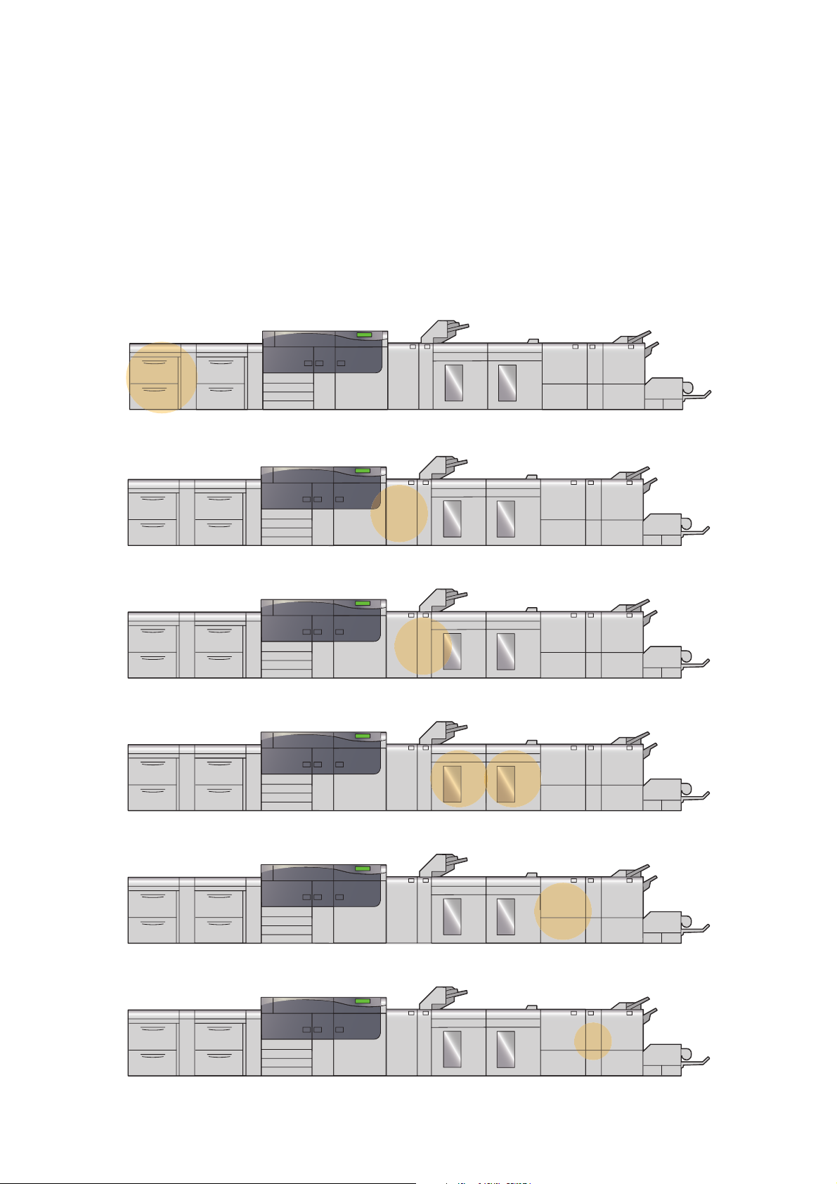
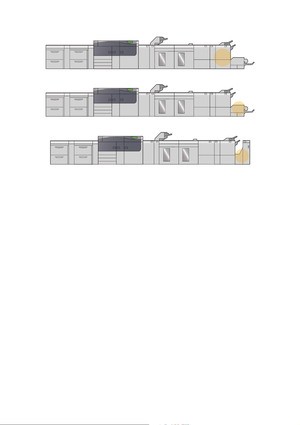
2nd High Capacity Feeder C1-DS
Interface Decurler Module
Inserter
High Capacity Stacker
Crease/Two-sided Trimmer
Fol der Unit
Finisher
SquareFold Trimmer
Finishing Transport
In this manual, safety instructions are preceded by the symbol . Always read and follow the instructions
before performing the required procedures.
It may be a legal offence to print currency notes, certificates of stocks and securities, or any other documents of
similar nature, regardless of whether they will be used.
If a malfunction occurs with the machine's hard disk or other storage media, any received or stored data including registered configurations may be lost. Fuji Xerox is not responsible for any direct or indirect damages arising
from or caused by such data loss.
Fuji Xerox is not responsible for any breakdown of machines due to infection of computer virus or computer hacking.
Important
1. This manual is copyrighted with all rights reserved. Under the copyright laws, this manual may not be copied
or modified in whole or part, without the written consent of the publisher.
2. Parts of this manual are subject to change without prior notice.
3. We welcome any comments on ambiguities, errors, omissions, or missing pages.
4. Never attempt any procedure on the machine that is not specifically described in this manual. Unauthorized
operation can cause faults or accidents. Fuji Xerox is not liable for any problems resulting from unauthorized
operation of the equipment.
An export of this product is strictly controlled in accordance with Laws concerning Foreign Exchange and Foreign Trade of Japan and/or the export control regulations of the United States.
Xerox, Xerox and Design, Fuji Xerox and Design, Versant as well as CentreWare are registered trademarks or trademarks of Xerox Corporation in Japan and/or other countries.
Other company names or product names are registered trademarks or trademarks of each company.
2
Optional Units Manual

Preface
Fuji Xerox Co.,Ltd.
Thank you for selecting the Versant 3100 Press.
The Versant 3100 Press is a color printing system that quickly processes data from client computers and
delivers high-quality outputs. The Versant 3100 Press consists of the printer unit and a variety of optional
units as well as a Print Server.
The Versant 3100 Press offer high-speed color printing: up to 100 sheets/minute (A4) (the actual speed
depends on the size, type, and weight of paper).
This manual is intended to provide first-time users of the Versant 3100 Press with necessary information
such as operating procedures and precautions on using the optional units.
Before using the Versant 3100 Press, please read this manual thoroughly to obtain the best performance
of the Versant 3100 Press.
After reading this manual, please keep it in a safe place for further reference. It will be useful in case you
forget how to perform operations or if a problem occurs with the printer.
For information on functions and operations of the Print Server, refer to customer documentation supplied
with Print Servers.
Preface
3

Table of Contents
Preface...................................................................................................................................................................................................................................... 3
Table of Contents................................................................................................................................................................................................................. 4
Types of Manuals................................................................................................................................................................................................................. 6
Using This Manual ............................................................................................................................................................................................................... 7
Chapter 1 2nd High Capacity Feeder C1-DS...........................................................................10
1.1 Machine Components ............................................................................................................................................ 10
1.2 Paper Jams.................................................................................................................................................................. 12
1.2.1 Paper Jams in Tray ...................................................................................................................................................... 12
1.2.2 Paper Jams inside the Right Side Cover ............................................................................................................. 14
1.2.3 Paper Jams in the Paper Feeding Unit ............................................................................................................... 17
Chapter 2 Interface Decurler Module.......................................................................................18
2.1 Machine Components ............................................................................................................................................ 18
2.2 Curl Correction........................................................................................................................................................... 19
2.3 Paper Jams.................................................................................................................................................................. 21
Chapter 3 Inserter............................................................................................................................23
3.1 Machine Components ............................................................................................................................................ 23
3.2 Loading Paper............................................................................................................................................................ 25
3.3 Paper Jams.................................................................................................................................................................. 26
Chapter 4 High Capacity Stacker ...............................................................................................30
4.1 Machine Component .............................................................................................................................................. 30
4.2 Output Paper.............................................................................................................................................................. 32
4.2.1 Output Trays .................................................................................................................................................................. 32
4.2.2 Control Buttons.............................................................................................................................................................32
4.3 Paper Jams.................................................................................................................................................................. 33
Chapter 5 Crease/Two-sided Trimmer ......................................................................................40
4
Optional Units Manual

5.1 Machine Components ............................................................................................................................................ 40
5.2 Trimmer Waste Container .................................................................................................................................... 43
5.3 Paper Jams.................................................................................................................................................................. 44
Chapter 6 Folder Unit .....................................................................................................................53
6.1 Machine Components ............................................................................................................................................ 53
6.2 Output Paper.............................................................................................................................................................. 54
6.3 Paper Jams.................................................................................................................................................................. 55
Chapter 7 Finisher............................................................................................................................59
7.1 Machine Components ............................................................................................................................................ 60
7.2 Output Paper.............................................................................................................................................................. 64
7.2.1 Output Trays .................................................................................................................................................................. 64
7.2.2 Control Buttons.............................................................................................................................................................66
7.3 Staple Cartridge........................................................................................................................................................ 67
7.3.1 Replacing the Cartridge ............................................................................................................................................67
7.3.2 Staple Faults...................................................................................................................................................................69
7.3.3 Re-inserting the Staple Cartridge.......................................................................................................................... 72
7.4 Waste Container....................................................................................................................................................... 74
7.4.1 Staple Waste Container............................................................................................................................................74
7.4.2 Hole Punch Waste Container..................................................................................................................................76
7.5 Paper Jams.................................................................................................................................................................. 77
7.5.1 Paper Jams in the Finisher ....................................................................................................................................... 77
7.5.2 Paper Jams in the Saddle Stitch Unit..................................................................................................................81
7.5.3 Paper Jams in the Paper Feeding Unit ............................................................................................................... 84
Chapter 8 SquareFold Trimmer...................................................................................................85
8.1 Machine Components ............................................................................................................................................ 85
8.2 Output Paper.............................................................................................................................................................. 87
8.2.1 Output Trays .................................................................................................................................................................. 87
8.2.2 Spine-flattener Strength Adjustment Button.................................................................................................. 87
8.3 Trimmer Waste Container .................................................................................................................................... 88
8.4 Paper Jams.................................................................................................................................................................. 89
Chapter 9 Finishing Transport.....................................................................................................92
9.1 Machine Components ............................................................................................................................................ 92
9.2 Paper Jams.................................................................................................................................................................. 93
Index ...................................................................................................................................................................................................................................... 96
Table of Contents
5

Types of Manuals
Refer
The Versant 3100 Press comes bundled with the following manuals:
For information on functions and operations of the Print Server, refer to customer documentation supplied
with Print Servers.
Some of them come with manuals. The manuals for optional components describe all the necessary steps
for using the optional components and installing the software.
For details on the functions of your 3rd Vendor Finisher or GBC® AdvancedPunch™ Pro, refer to the manual
supplied with the device.
PDF Manual
The Manuals are stored as PDF files on the Versant 3100 Press Instruction Manuals CD.
Double-click "index.html" and select the language of the manual you wish to display.
Versant 3100 Press Optional Units Manual (this manual)
Describes how to replace consumables and how to clear paper jams in the optional units (High Capacity
Stacker, Finisher, and others).
Versant 3100 Press Printer Unit Manual
Describes how to load paper, how to replace consumables, how to clear paper jams, and the daily maintenance procedures for the printer unit. (These descriptions are also applied to the printer unit equipped
with Offset Catch Tray.)
Versant 3100 Press User Interface Manual
Describes the operations of the user interface (UI) for operating the printer.
The user interface allows you to confirm status of the printer, and to set the printer behavior.
Versant 3100 Press Paper Jams: Quick Access Guide
Illustrates possible paper jam areas, allowing you to quickly identify a paper jam location.
HTML Manual
Stock Library Manager Manual
Describes Stock Library Manager with which you can change the paper settings.
The manual can be viewed from the [Help] menu of Stock Library Manager.
CentreWare Internet Services Help
The help describes CentreWare Internet Services where you can change various settings of the printer
using a client computer.
Click [Help] in the upper right corner of CentreWare Internet Service window to display the help.
To display the online help for CentreWare Internet Services, users need to have the environment to connect
Important
to the Internet. The communication fee shall be borne by you.
Paper Manual
6
Versant 3100 Press Safety Notes
Provides information for using the printer safely. Read this manual before using the printer.
Optional Units Manual
Using This Manual
This manual is intended to provide first-time users of the Versant 3100 Press with necessary information
such as operating procedures and precautions on using the optional units.
Organization of This Manual
This manual identifies components as well as covers procedures to clear paper jams for each of the
optional units.
Chapter 1 2nd High Capacity Feeder C1-DS
Chapter 2 Interface Decurler Module
Chapter 3 Inserter
Chapter 4 High Capacity Stacker
Chapter 5 Crease/Two-sided Trimmer
Chapter 6 Folder Unit
Using This Manual
7
Chapter 7 Finisher
Chapter 8 SquareFold Trimmer
Chapter 9 Finishing Transport
8
Optional Units Manual

Conventions
Note
Important
Note
Refer
Bottom
Feed direction
Front edge
Portrait
Landscape
To p
Rear edge
This manual uses the following symbols:
Indicates important information you have to know or be reminded before operations.
Indicates supplemental information useful for operations.
Indicates references to other chapters and manuals.
< > Indicates the Control Panel, and buttons and lamps on the printer or optional units.
[ ] Indicates the names of tabs, options, buttons, menus and file names on the touch screen
display.
" " Indicates the names of reference sections in this manual, characters to be entered, path
names, and messages.
XXX Manual Indicates the names of the reference manuals.
Paper
Orientation
There are two paper orientations: Long Edge Feed (LEF) and Short Edge Feed (SEF).
The figures below describe front, rear, top, and bottom edges of the paper for LEF and
SEF.
Long Edge Feed (LEF )
Long edge: landscape (width),
Short edge: portrait (height)
The front of the printer The front of the printer
The feed direction shown above works in an opposite manner for Printer Unit Trays and Inserter Tray.
Short Edge Feed (SEF )
Short edge: landscape (width),
Long edge: portrait (height)
To p
Landscape
Rear edge
Feed direction
Bottom
Illustrations in This Manual
All illustrations contained in this manual are of the product equipped with all optional units.
Front edge
Portrait
Using This Manual
9
Chapter 1
Refer
1.1 Machine Components............................................................................10
1.2 Paper Jams..................................................................................................12
For detailed information on how to load paper, refer to "2.3 Loading Paper" in the Printer Unit Manual, and
how to clean the printer, refer to "4.3 Cleaning the Printer" in the Printer Unit Manual.
2nd High Capacity Feeder C1-DS
1.2.1 Paper Jams in Tray.............................................................................................. 12
1.2.2 Paper Jams inside the Right Side Cover .................................................... 14
1.2.3 Paper Jams in the Paper Feeding Unit....................................................... 17
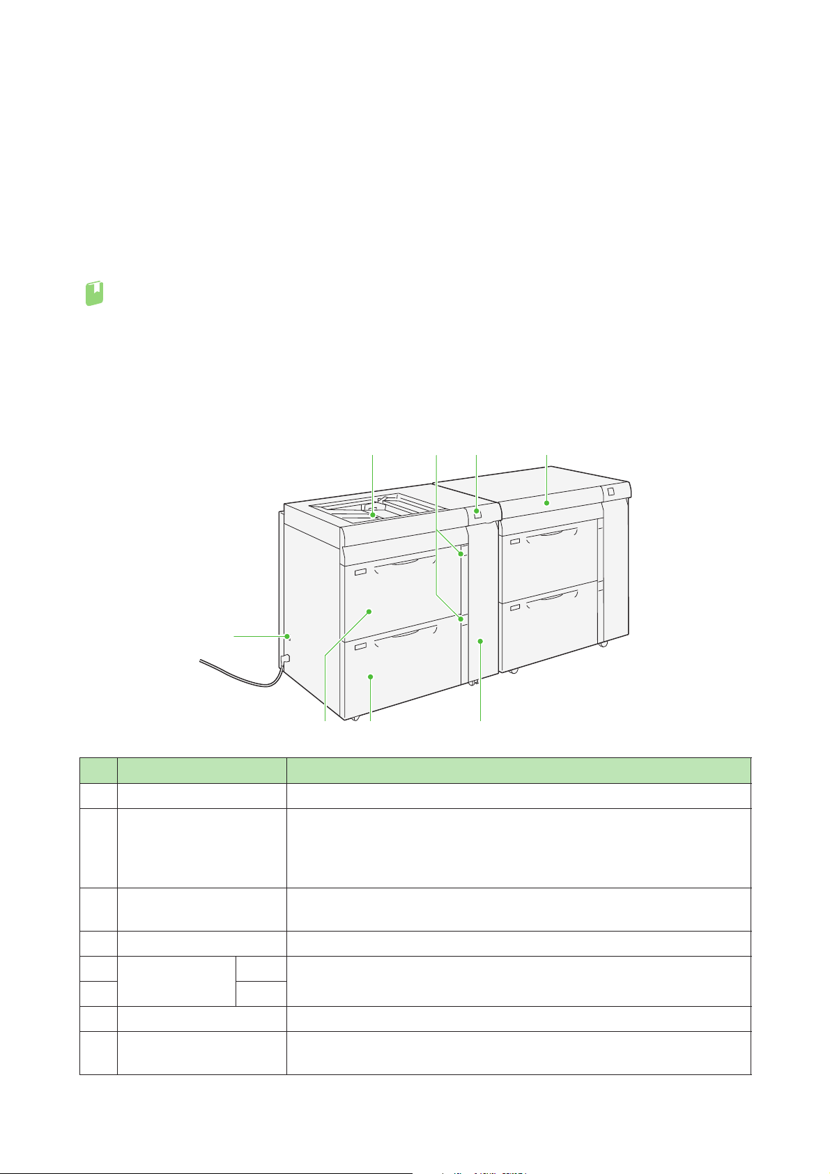
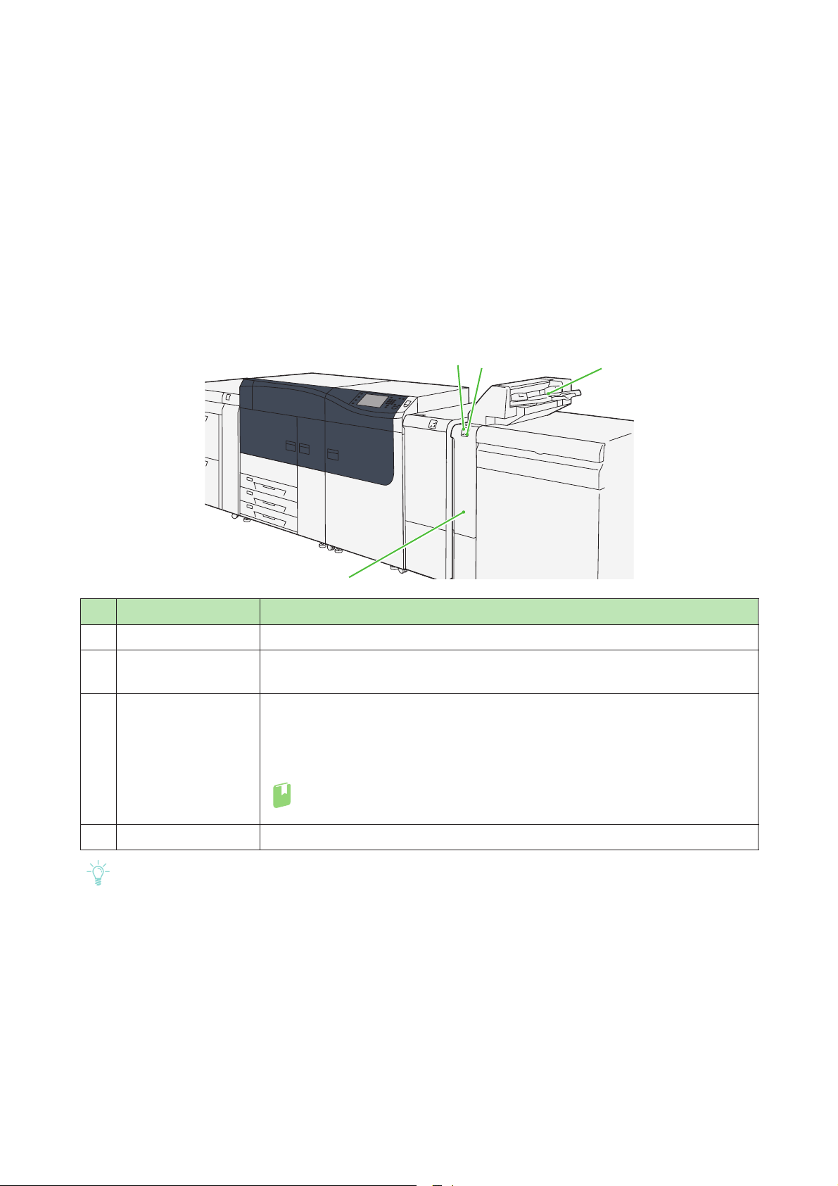
1.1
No, Component Description
Machine Components
3 8
4
12
765
10
1 Error lamp Illuminates when a paper jam occurs.
Paper level indicator lamp The top active indicator lamp lights when the corresponding Tray is active.
2
Bypass Tray (Tray 5) Load paper here.
3
4 Circuit breaker switch Automatically shuts off electricity in the event of fault current or a short circuit.
5 High Capacity
Trays
6 Tray 9
7 Right side cover Open this cover to clear paper jams.
Top cover of High Capacity
8
Feeder C3-DS
Optional Units Manual
Tray 8 Load paper here.
The four center lamps (1=25%) indicate the amount of remaining paper.
When all of the four lamps turn off, Tray becomes empty and paper empty
indicator lamp lights.
Images are printed on the face side of the loaded paper.
Images are printed on the face side of the loaded paper.
Open this cover to clear paper jams.
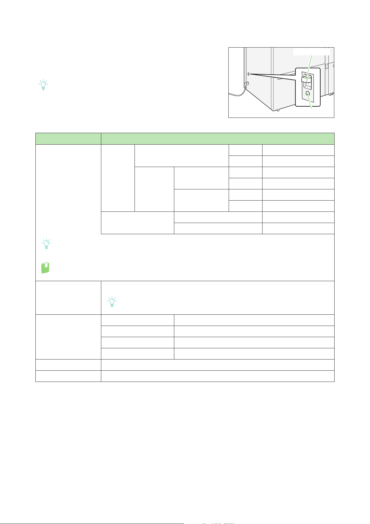
Circuit Breaker Switch
Note
Note
Refer
Note
TEST button
Breaker switch
The switch is normally in the upper position.
If the machine will be moved or unused for an extended period of
time, turn off the switch by pressing it to the lower position.
When fault current is detected, the circuit breaker is automatically turned off to discontinue the electrical flow. Do not touch
the breakers under normal condition. For information on fault
current, refer to the Safety Notes.
Specifications
Component Description
Paper size
Paper weight
Paper size Standard size Maximum A3, 13 x 19"
Minimum Post Card (100 x 148 mm)
Custom size Bypass Tray Height 98.0 - 330.2 mm
Width 148.0 - 660.4 mm
High Capacity Tray Height 98.0 - 330.2 mm
Width 148.0 - 488.0 mm
Paper weight Bypass Tray 52 - 300 g/m
High Capacity Tray 52 - 350 g/m
Printing on long paper can cause decreased continuous printing speed.
There is a certain limitation on how long paper can be fed and delivered.
For detailed information about the supported paper size and weight, refer to "2.1.2 Supported Paper" in
the Printer Unit Manual.
2
2
Tray capacity 2,000 sheets x 2 Trays (Maximum capacity: 4,000 sheets), Bypass Tray: 250 sheets
The values are based on Colotech+90.
Power supply
Power consumption
Power supply 100 - 120 V AC ±10%, 5 A, 50 Hz or 60 Hz
Peak 500 W
Power supply 200 - 240 V AC ±10%, 3 A, 50 Hz or 60 Hz
Peak 660 W
Dimension Width 988 x Depth 762 x Height 992 mm
Weight 222 kg (When it is installed.)
Chapter 1 2nd High Capacity Feeder C1-DS
11
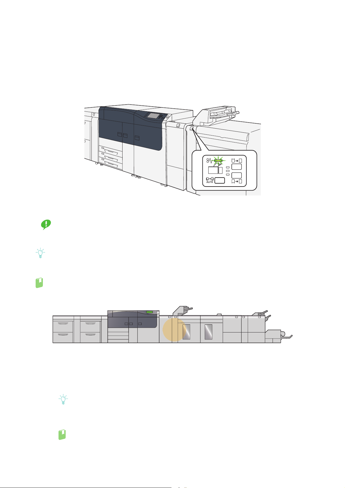
1.2
Note
Refer
Paper Jams
If there is a paper jam, the printing will be canceled.
The Error Message area of the touch screen will show the affected area in red, along with the message.
Also, the error lamp on the top of the machine will illuminate.
If there is a paper jam in the following area, tap the [Faults] and the [Faults] screen will appear, explaining
how to remove jammed papers.
Remove the paper only after you are sure the printer is no longer moving.
Important
After removing jammed papers, be sure to close the cover. Leaving the cover open will not be able to continue to print jobs.
Leave the power on and proceed to remove jammed papers.
If there is still paper remaining, the paper jam message will continue to display. Make sure that there is no
jammed paper left and also no jams in other places.
For detailed information on how to regard the messages, refer to "1.2.1 Services Home" in the User Interface
Manual.
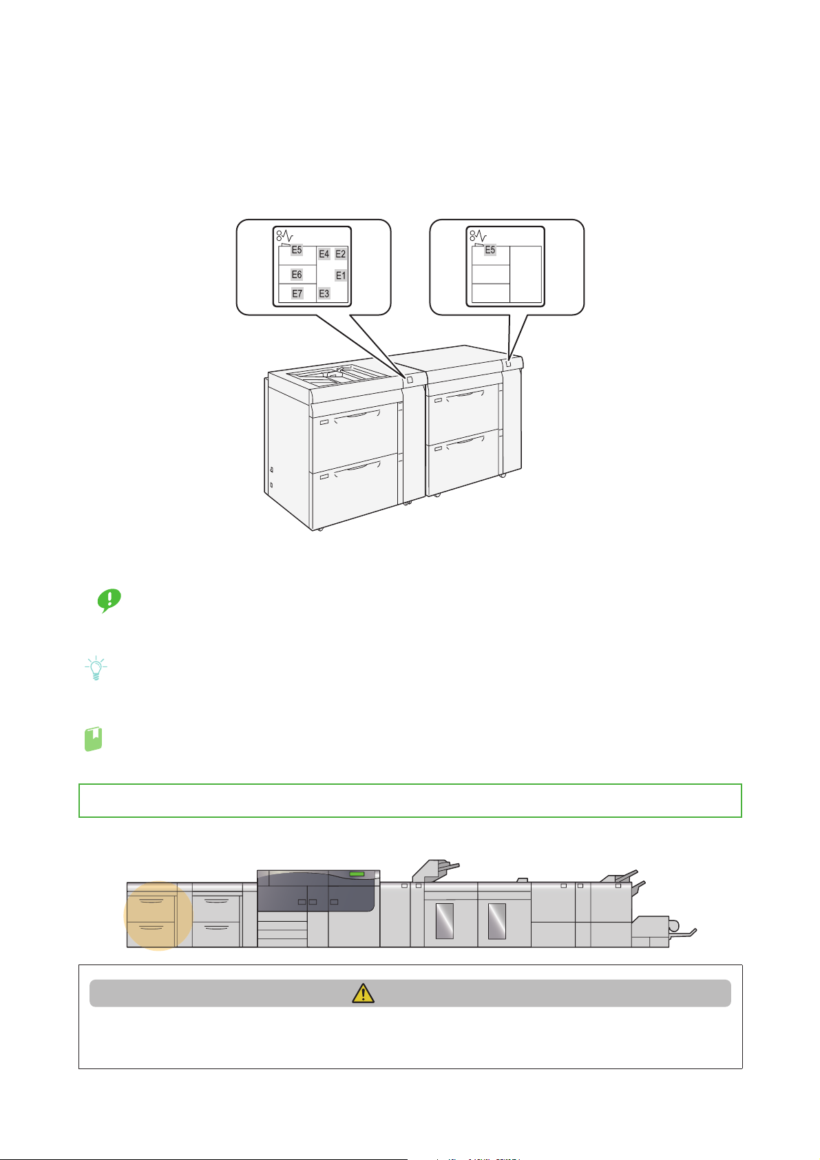
1.2.1 Paper Jams in Tray
Follow the steps below to clear paper jams in Tray.
12
CAUTION
When pulling out the Tray, do it gently. If pulled out with too much force, the Tray can hit and injure
your knees.
Optional Units Manual
1.
Note
Important
Refer
Important
Remove jammed papers.
When Lamp E5 is Lit...........................................................................................................................................................p.13
When Lamp E6 is Lit...........................................................................................................................................................p.13
When Lamp E7 is Lit...........................................................................................................................................................p.14
Solutions differ depending on where the paper jam occurs. Confirm the jammed area in the Error
Message area.
The code (E) on the upper-left part of the message indicates which error lamp on the top of the
machine is illuminating.
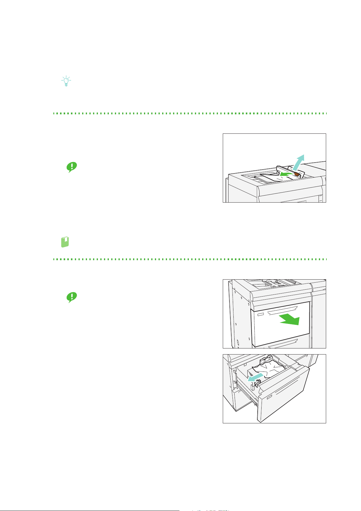
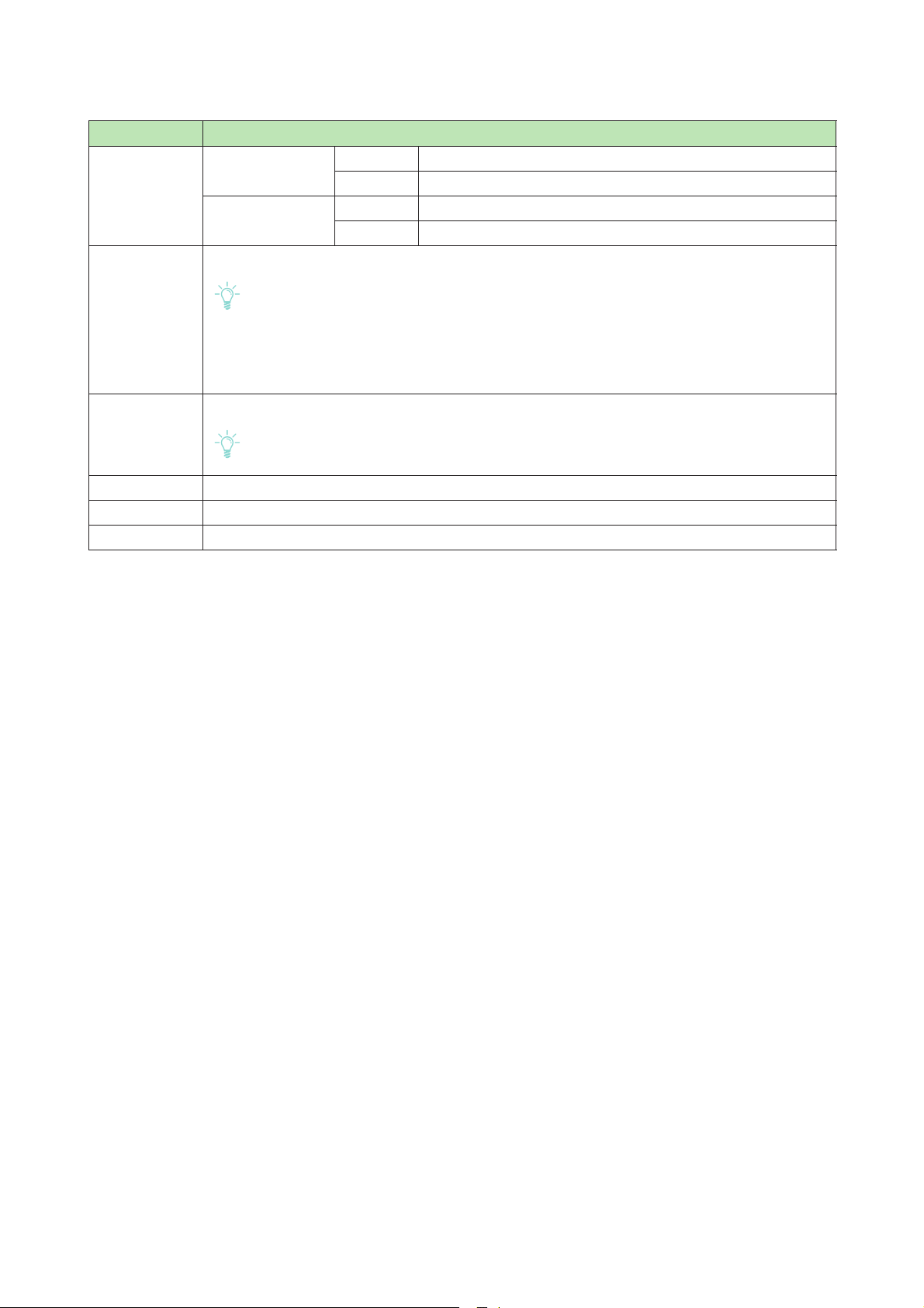
When Lamp E5 is Lit
(1) Open the cover on the top of the Bypass Tray, and
remove jammed papers and all papers loaded in the
Bypass Tray.
When two or more sheets of paper are loaded,
remove all the sheets from the Tray.
(2) Close the cover.
(3) Fan the paper you removed and make sure all four
corners are aligned correctly. Then reload the paper.
If you have difficulty in removing jammed papers, open
the cover on the right side to remove the paper inside.
For detailed information on paper jams inside the right side cover, refer to "1.2.2 Paper Jams inside
the Right Side Cover" (p.14).
When Lamp E6 is Lit
(1) Pull out the Tray 8 toward you until it stops.
Before pulling out the Tray, make sure no paper is
jammed inside the right side cover.
(2) Remove jammed papers.
(3) Make sure the long-side and short-side paper guides are positioned to just touch the
paper, and then push the Tray into the machine.
Chapter 1 2nd High Capacity Feeder C1-DS
13
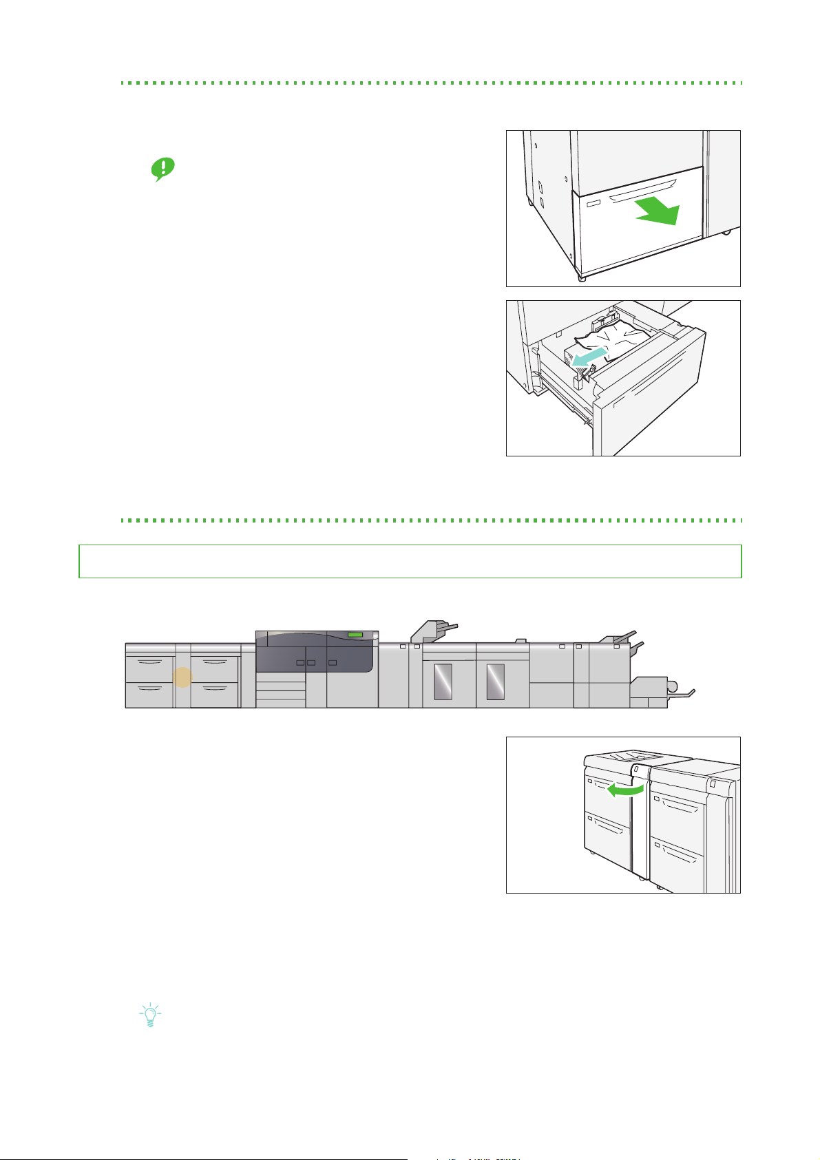
When Lamp E7 is Lit
Important
Note
(1) Pull out the Tray 9 toward you until it stops.
Before pulling out the Tray, make sure no paper is
jammed inside the right side cover.
(2) Remove jammed papers.
(3) Make sure the long-side and short-side paper guides are positioned to just touch the
paper, and then push the Tray into the machine.
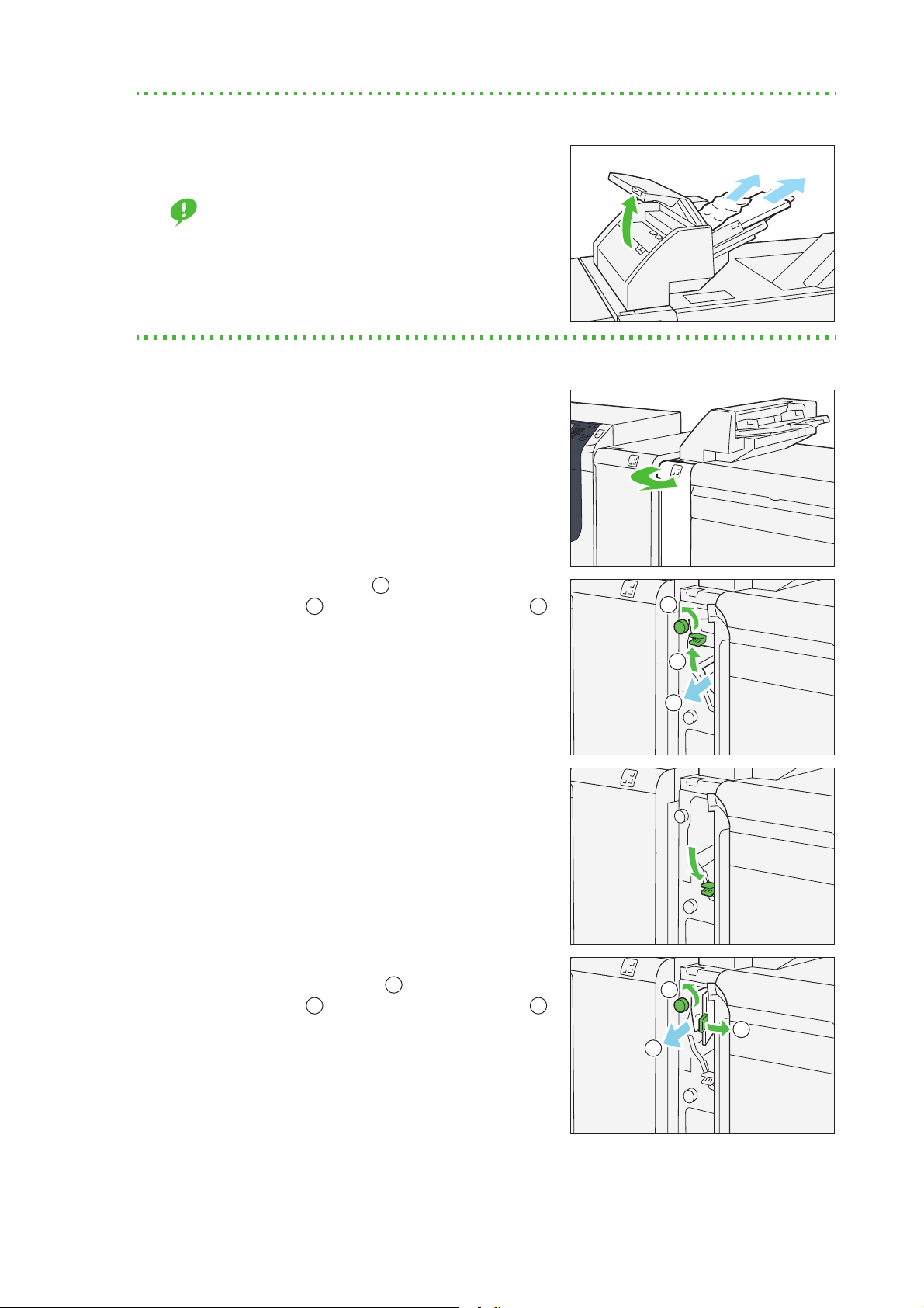
1.2.2 Paper Jams inside the Right Side Cover
Follow the steps below to clear paper jams inside the cover of the 2nd High Capacity Feeder C1-DS.
1.
Open the right side cover of the 2nd High Capacity
Feeder C1-DS.
2.
Remove jammed papers.
When Lamp E1 is Lit...........................................................................................................................................................p.15
When Lamp E2 is Lit...........................................................................................................................................................p.15
When Lamp E3 is Lit...........................................................................................................................................................p.16
When Lamp E4 is Lit...........................................................................................................................................................p.16
14
Solutions differ depending on where the paper jam occurs. Confirm the jammed area in the Error
Message area.
The code (E) on the upper-left part of the message indicates which error lamp on the top of the
machine is illuminating.
Optional Units Manual
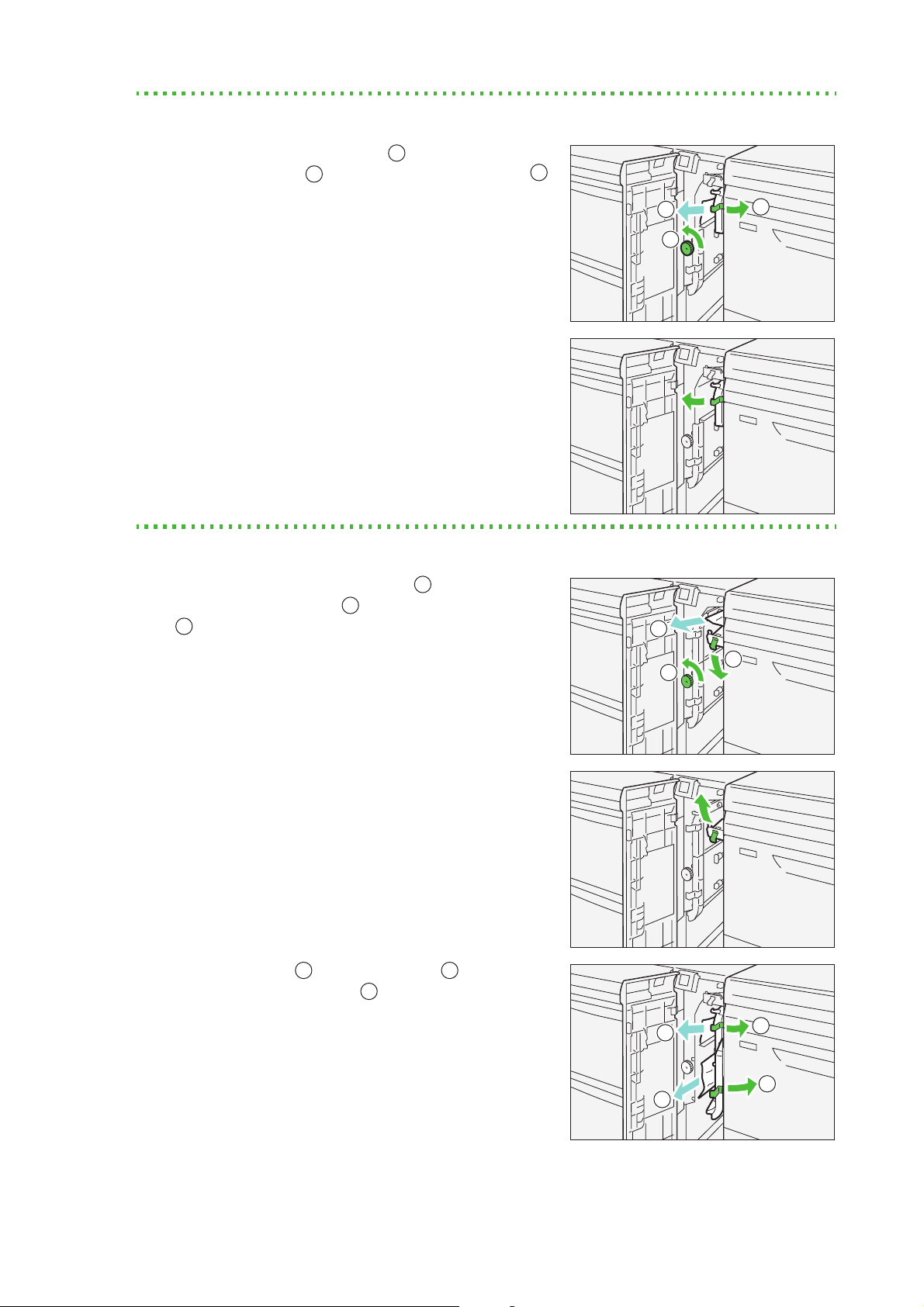
When Lamp E1 is Lit
2
1
3
1
3
1
2
3
1
3
1
2
3
3
1
3
(1) Open lever "1a" to the right ( ) and turn knob "1c"
counterclockwise ( ). Remove jammed papers ( ).
2
(2) Return lever "1a" to its original position.
When Lamp E2 is Lit
(1) Open lever "1d" to downward ( ) and turn knob
"1c" counterclockwise ( ). Remove jammed papers
2
().
(2) Return lever "1d" to its original position.
(3) Open lever "1a" ( ) and lever "1b" ( ) to the right.
2
Remove jammed papers ( ).
Chapter 1 2nd High Capacity Feeder C1-DS
15
(4) Return levers "1a" and "1b" to their original positions.
1
2
3
1
3
1
2
3
3
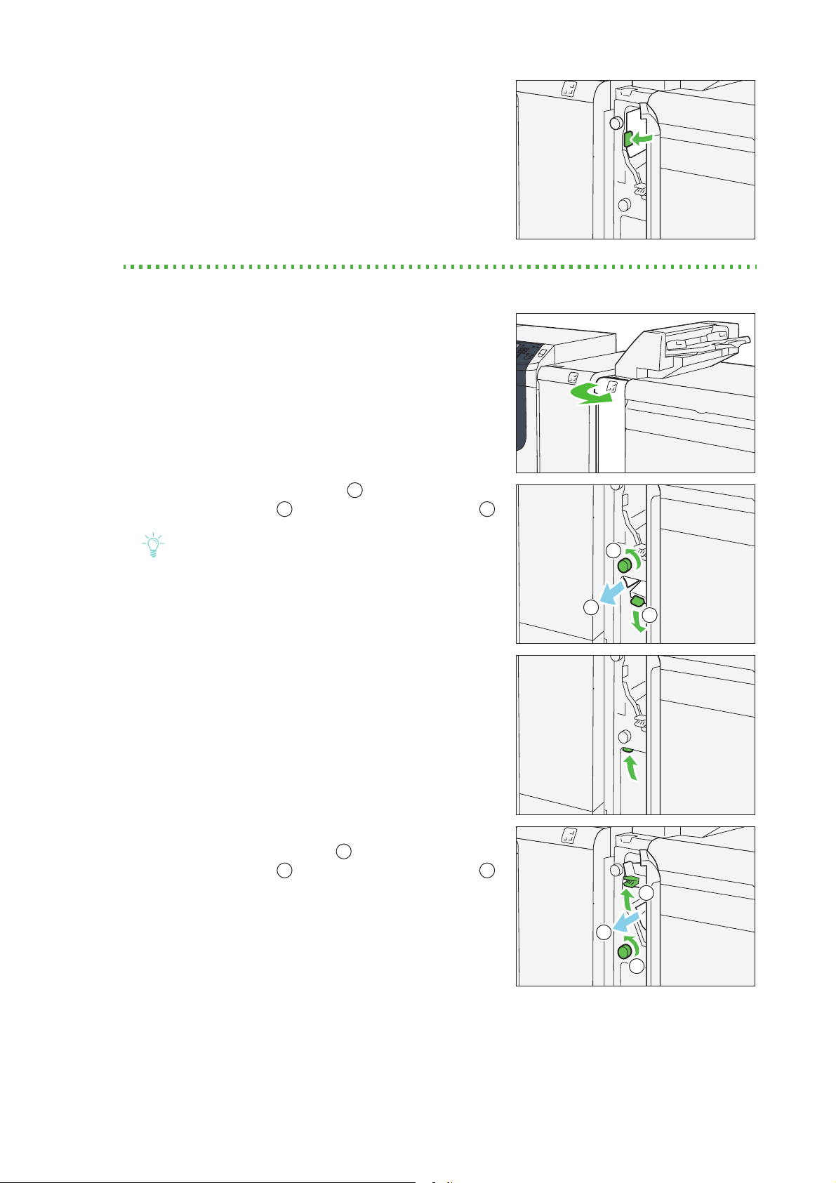
When Lamp E3 is Lit
(1) Open lever "1b" to the right ( ) and turn knob "1c"
counterclockwise ( ). Remove jammed papers ( ).
2
(2) Return lever "1b" to its original position.
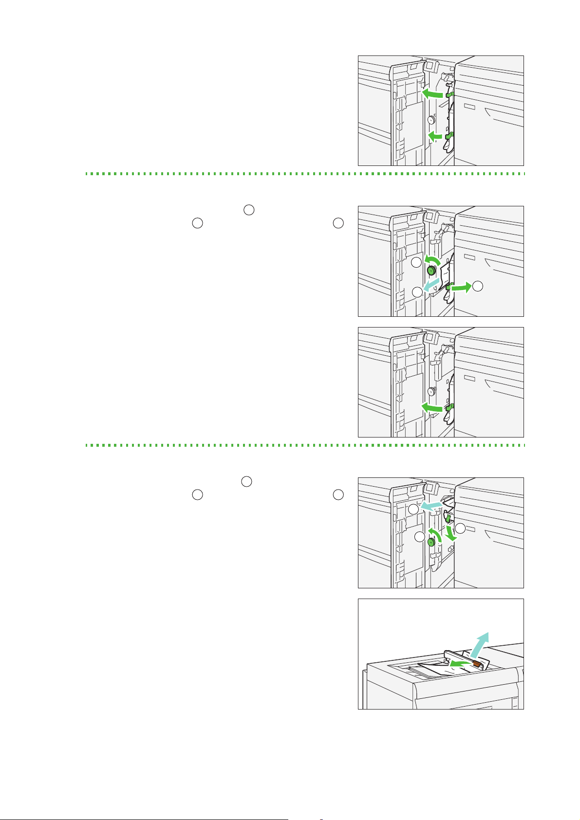
When Lamp E4 is Lit
(1) Open lever "1d" downward ( ) and turn knob "1c"
counterclockwise ( ). Remove jammed papers ( ).
2
1
(2) If you have difficulty in removing jammed papers,
loaded in the Bypass Tray, open the top cover and
remove them.
16
Optional Units Manual
(3) Return lever "1d" to its original position.
Note
Important
1
2
3
1
2
3
1
2
3.
Close the cover.
1.2.3 Paper Jams in the Paper Feeding Unit
Follow the steps below to clear paper jams in the paper feeding unit.
The "E5" error lamp of the High Capacity Feeder C3-DS will illuminate.
1.
Pull out the top cover of the High Capacity Feeder
C3-DS toward you until it stops.
Before pulling out the Tray, make sure no paper is
jammed inside the right side cover.
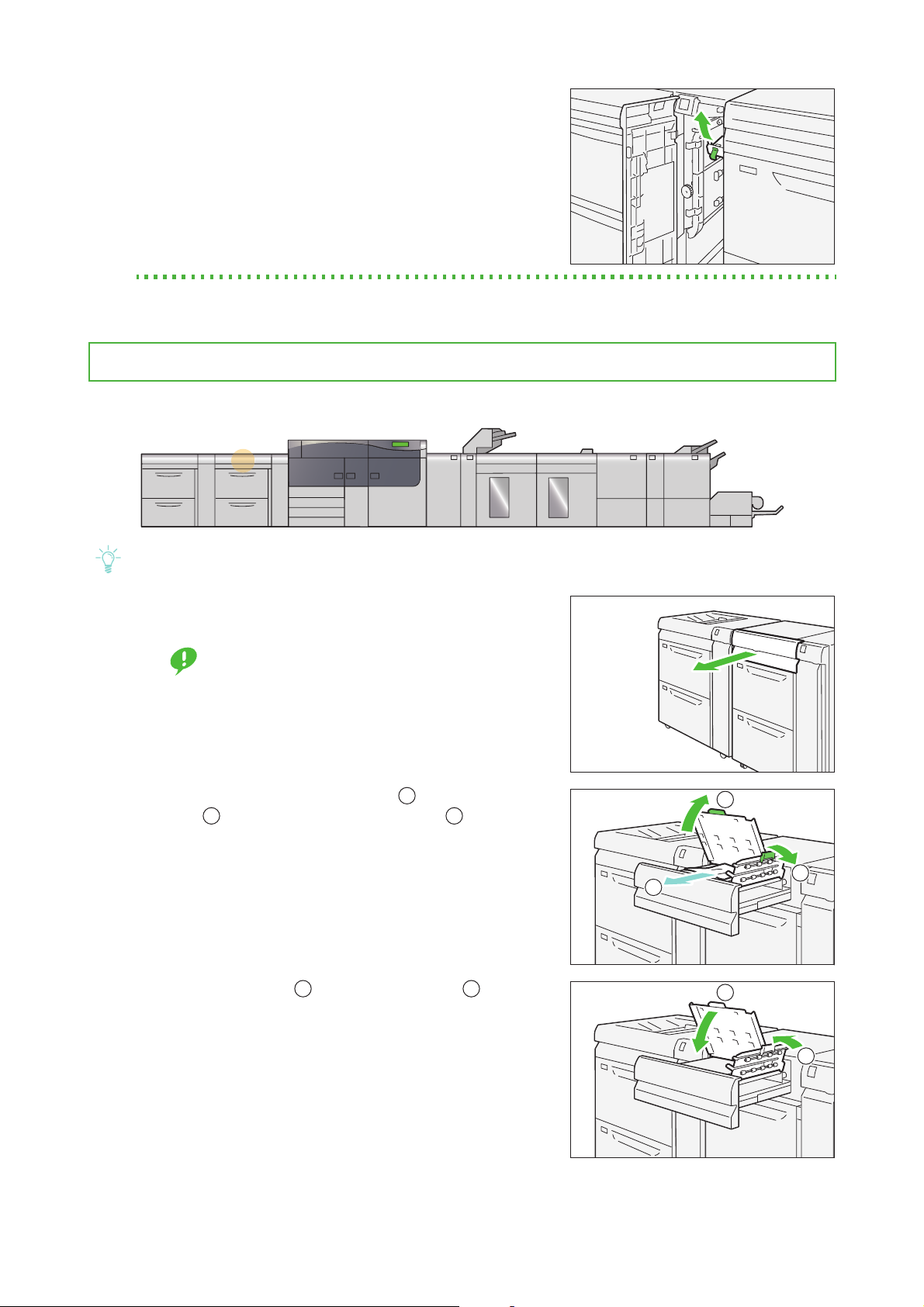
2.
Open lever "2a" to the right ( ) and lever "2b"
upward ( ). Remove jammed papers
3.
Return levers "2a" ( ) and lever "2b" ( ) to their
1
()
2
original positions.
.
4.
Close the cover.
Chapter 1 2nd High Capacity Feeder C1-DS
17
Chapter 2
Note
2
1
3
2.1 Machine Components............................................................................18
2.2 Curl Correction...........................................................................................19
2.3 Paper Jams..................................................................................................21
Interface Decurler Module
2.1
No. Component Description
1
2
Machine Components
Error lamp Illuminates when a paper jam occurs.
If the lamp is blinking, you must first clear the paper jam.
Decurl button Press this button to correct the curl.
This function is to correct the curl while sheets are being printed.
3 Cover Open this cover to clear paper jams.
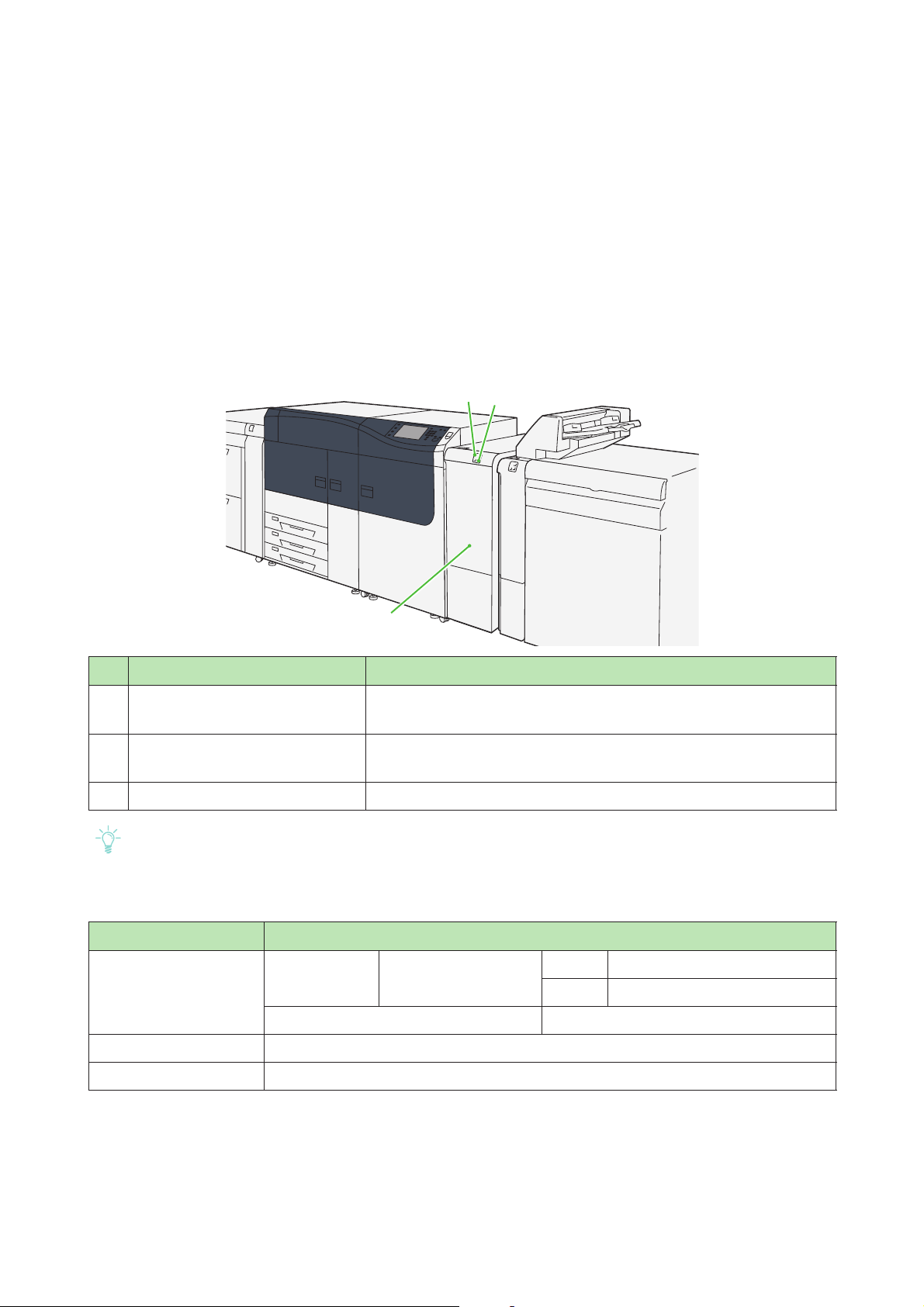
The Interface Decurler Module is required when connecting a paper discharge unit to the printer unit.
Specifications
Item Specification
Power supply
Power consumption
Dimensions Width 340 x Depth 725 x Height 992 mm
Weight 40 kg
Power supply 100 - 240 V AC±10% 100 V 2.5 A, 50 Hz or 60 Hz
240 V 1 A, 50 Hz or 60 Hz
Peak 250 W
18
Optional Units Manual
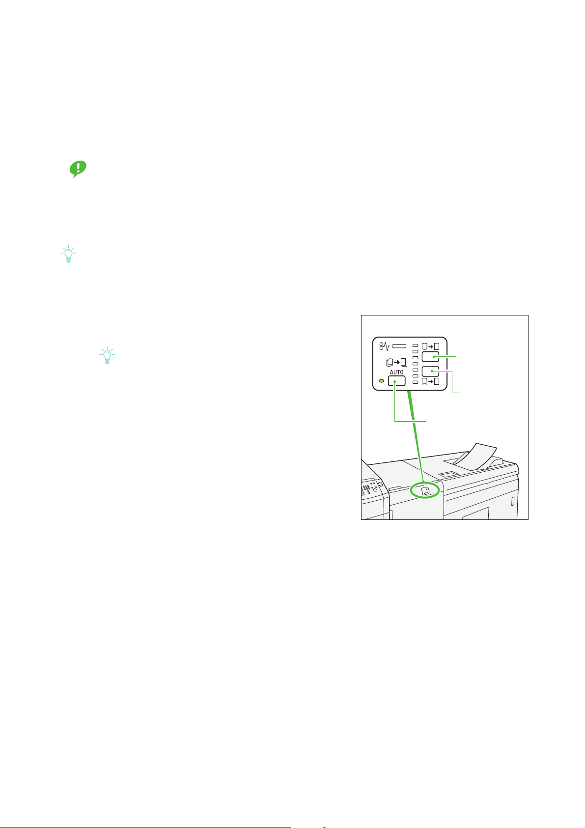
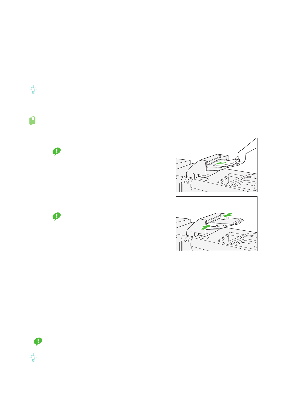
2.2
Important
Note
Note
Upward curl
correction button
<AUTO> button
Downward
curl correction button
Curl Correction
By pressing decurl buttons, you can correct the paper curl caused by heat and pressure.
As far as the printer is powered on, the decurl buttons function regardless of whether the printer is running
or idle.
This curl correction function is intended to be used during printing. Fine adjustment according to the characteristics of each paper can be made by using Stock Library.
For detailed information on how to regard the Stock Library, refer to "Stock Library" in the Stock Library
Manager Manual.
Since paper curl can easily cause stapling problems, make sure you always check the curl direction of output paper to properly correct paper curl.
If you correct curl while the printer is running, the new mode is applied to the sheet delivered immediately
after the button is pressed.
1.
Check the curl direction of output paper.
2.
Make sure a decurl button lamp is lit and press the
button.
When feeding paper in "AUTO" mode, the lamps illuminate briefly to indicate the direction and level of
correction as paper curl is corrected. Use these lamps
as a guide when correcting paper curl manually.
Chapter 2 Interface Decurler Module
19
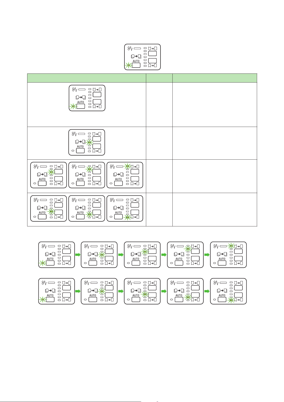
Curl correction modes and functions of the decurl buttons
Press the <AUTO> button to switch to the "AUTO" mode.
Indicator Mode Function
AUTO Automatically corrects paper curl.
No rmally i t is recomm ended to sel ect this
mode.
The module selects the optimal curl
adjustment method, depending on the
size and delivery orientation of the
printed output.
OFF The machine will not perform the curling
correction to straighten the curled
printed output.
Upward
Curling
Downward
Curling
Select this when the printed output print
is curled upwards, in order to apply
upward curl correction.
The correction level is indicated by the
lamp, with the top being the highest.
Select this when the printed output is
curled downwards, in order to apply
downward curl correction.
The correction level is indicated by the
lamp, with the bottom being the lowest.
Pressing the upward curl correction button changes correction levels as follows.
Pressing the downward curl correction button changes correction levels as follows.
20
Optional Units Manual
2.3
Note
Refer
Refer
E1
E2
E3
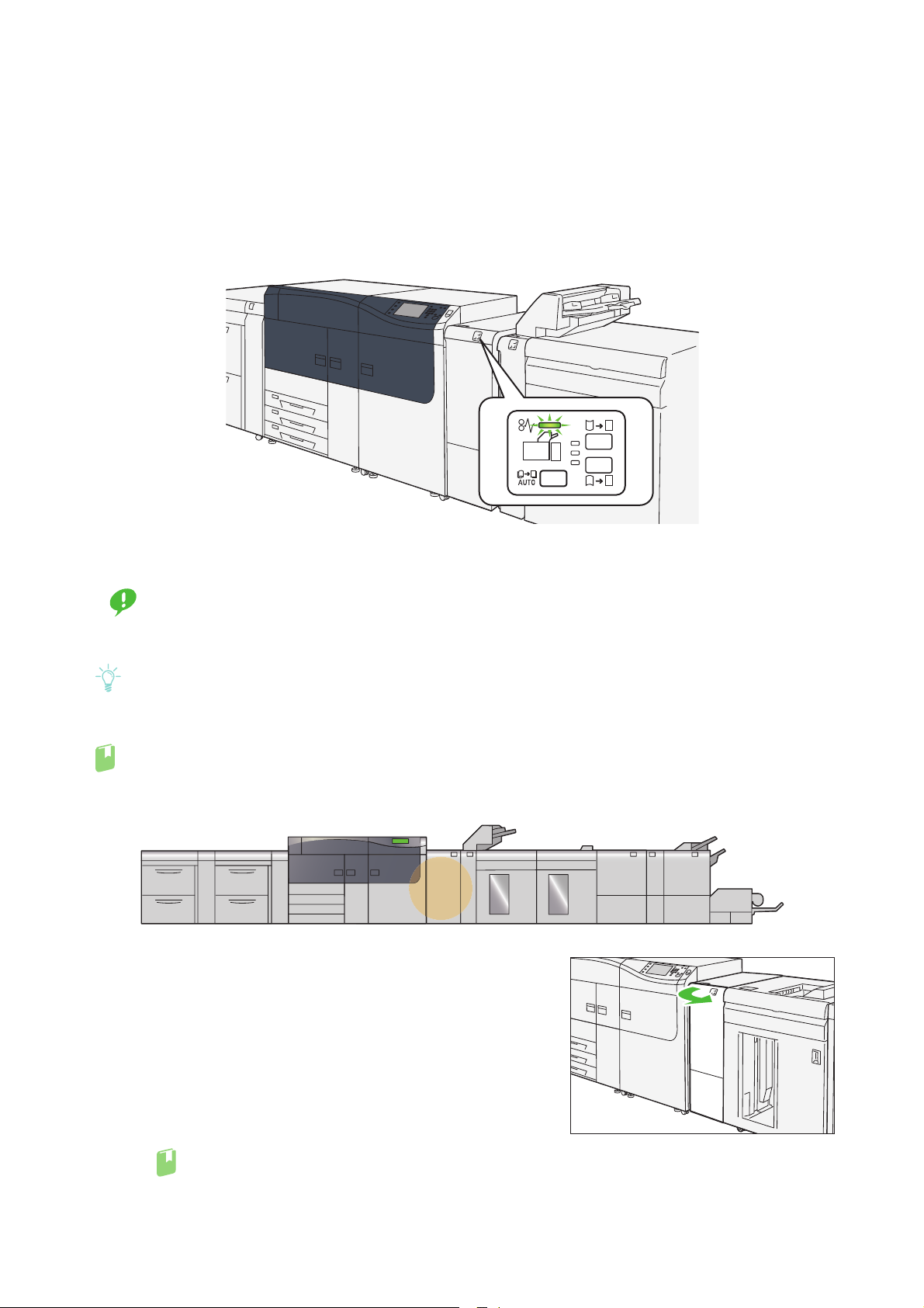
Paper Jams
If there is a paper jam, the printing will be canceled.
The Error Message area of the touch screen will show the affected area in red, along with the message.
Also, the error lamp on the top of the machine will illuminate.
If the lamp is blinking, you must first clear the paper jam.
If there is a paper jam in the following area, tap the [Faults] and the [Faults] screen will appear, explaining
how to remove jammed papers.
Remove the paper only after you are sure the printer is no longer moving.
Important
After removing jammed papers, be sure to close the cover. Leaving the cover open will not be able to continue to print jobs.
Leave the power on and proceed to remove jammed papers.
If there is still paper remaining, the paper jam message will continue to display. Make sure that there is no
jammed paper left and also no jams in other places.
For detailed information on how to regard the messages, refer to "1.2.1 Services Home" in the User Interface
Manual.
Follow the steps below to clear paper jams in the Interface Decurler Module.
1.
Open the cover of the Interface Decurler Module.
If the jammed long paper is lying across more than one unit, refer to "3.3.4 Long Paper Jam" in the
Printer Unit Manual.
Chapter 2 Interface Decurler Module
21
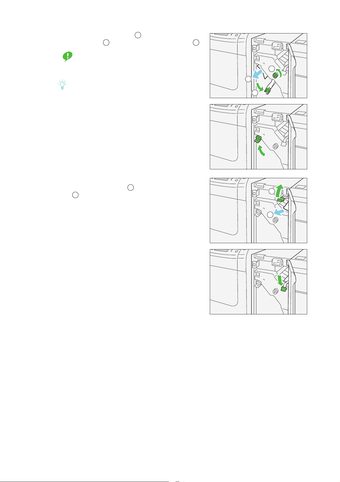
2.
Important
Note
1
2
3
2
3
1
2
1
2
Open lever "1a" downward ( ) and turn knob "1b"
1
counterclockwise ( ). Remove jammed papers ( ).
Make sure you turn the knob 10 times or more.
When removing the jammed paper, carefully
remove it by gently pulling it out.
The jammed paper may be hidden behind the upper
covering.
3.
Return lever "1a" to its original position.
4.
If you have difficulty in removing jammed papers,
open lever "1c" upward ( ) and remove jammed
papers ( ).
5.
Return lever "1c" to its original position.
6.
Close the cover.
22
Optional Units Manual
Chapter 3
Note
Refer
1
3
2
4
3.1 Machine Components............................................................................23
3.2 Loading Paper............................................................................................25
3.3 Paper Jams..................................................................................................26
Inserter
3.1
No. Component Description
1 Inserter Tray (Tray T1) Load paper to be used for separators or covers sheets.
2
Machine Components
Error lamp Illuminates when a paper jam occurs.
If the priority unit lamp is blinking, you must first clear the paper jam.
Decurl button Use this button if paper curl still persists after setting the curl correction level to the
highest (or the lowest) on the Interface Decurler Module. Steps to correct paper curl is
the same as those for the Interface Decurler Module. This button, however, provides
3
4 Cover Open this cover to clear paper jams.
The Inserter can be only attached to the Interface Decurler Module.
you with three correction levels only: OFF, upward and downward.
For information about the Curl Correction in the Interface Decurler Module, refer to "2.2 Curl Correction" (p.19).
Chapter 3 Inserter
23
Specifications
Note
Item Specification
Paper size Standard size Maximum A3, 13 x 19"
Minimum JIS B5
Custom size Height 182.0 - 330.2 mm
Width 148.0 - 488.0 mm
Paper weight 52 - 350 g/m
2
Note
Make sure you use Bypass Tray when using the combination of the following paper types
and Saddle Stitch / Bi-fold, because the combination can cause misalignment of folding
positions and wrinkle:
Coated Paper weighing 127 g/m2 or lighter
Blank sheets (unprinted paper) weighing 80 g/m2 or lighter
Tray capacity 250 sheets
The values are based on Colotech+90.
Power supply Supplied from the Interface Decurler Module
Dimensions Width 700 x Depth 725 x Height 1,228 mm (The width of the paper feeding unit is 165 mm.)
Weight 45 kg
24
Optional Units Manual
3.2
Note
Refer
Important
Important
Important
Note
Load paper to be used for separators or covers sheets (blank or printed sheets).
The Inserter Tray is used for feeding separator or cover sheets. These sheets are not printed by the
machine.
Up to 250 sheets (Colotech+90) can be loaded.
1.
Loading Paper
If any paper remains in the Tray, remove the paper first, and put the paper and the new papertogether,
and then load all of the paper into the Tray at once.
Saddle Stitch / Bi-fold can be performed only when using paper of the same size as main paper (paper
sheets delivered from the printer unit).
For detailed information about the supported paper size and weight, refer to "2.1.2 Supported Paper" in the
Printer Unit Manual.
Load the paper, neatly aligning all edges.
Do not load paper above the maximum fill line. It
may cause paper jams or machine malfunctions.
2.
Hold the center of the paper guides and slide them to
the desired paper size.
Slide the guides gently to just touch the edges of the
paper. If the distance between the guides is too long
or short relative to the paper, paper jams may occur.
Special Media Setting
Hole punched paper
Orientation: Place the holes of paper on the right side when you face the front side of the Inserter.
Precut tab
Orientation: Place the precut tab of paper on the left side when you face the front side of the Inserter.
Purge Function
The printer stops printing when paper runs out. When this happens, sheets of paper being fed are delivered to the optional unit's output tray.
Do not reuse the sheets ejected by the Purge function, as this may cause paper jams.
You can also set so that purging does not occur when paper runs out.
For detailed information, refer to "4.1.8 Maintenance" in the User Interface Manual.
Chapter 3 Inserter
25
3.3
Note
Refer
Note
Refer
E1
E2
E3
Paper Jams
If there is a paper jam, the printing will be canceled.
The Error Message area of the touch screen will show the affected area in red, along with the message.
Also, the error lamp on the top of the machine will illuminate.
If the priority unit lamp is blinking, you must first clear the paper jam.
If there is a paper jam in the following area, tap the [Faults] and the [Faults] screen will appear, explaining
how to remove jammed papers.
Remove the paper only after you are sure the printer is no longer moving.
Important
After removing jammed papers, be sure to close the cover. Leaving the cover open will not be able to continue to print jobs.
Leave the power on and proceed to remove jammed papers.
If there is still paper remaining, the paper jam message will continue to display. Make sure that there is no
jammed paper left and also no jams in other places.
For detailed information on how to regard the messages, refer to "1.2.1 Services Home" in the User Interface
Manual.
Follow the steps below to clear paper jams in the Inserter.
1.
Remove jammed papers.
When Lamp E1 is Lit...........................................................................................................................................................p.27
When Lamp E2 is Lit...........................................................................................................................................................p.27
When Lamp E3 is Lit...........................................................................................................................................................p.28
26
Solutions differ depending on where the paper jam occurs. Confirm the jammed area in the Error
Message area.
The code (E) on the upper-left part of the message indicates which error lamp on the top of the
machine is illuminating.
If the jammed long paper is lying across more than one unit, refer to "3.3.4 Long Paper Jam" in the
Printer Unit Manual.
Optional Units Manual
When Lamp E1 is Lit
Important
1
2
3
1
3
1
2
3
3
(1) Open the cover, and remove jammed papers and all
paper loaded in the Tray.
When two or more sheets of paper are loaded,
remove all sheets.
(2) Fan the paper you removed and make sure all four
corners are aligned correctly. Then reload the paper.
(3) Push the cover to close it.
When Lamp E2 is Lit
(1) Open the cover of the Inserter.
(2) Open lever "1a" upward ( ) and turn knob "1b"
counterclockwise ( ). Remove jammed papers ( ).
2
(3) Return lever "1a" to its original position.
(4) If you have difficulty in removing jammed papers,
open lever "1c" to the right ( ) and turn knob "1b"
counterclockwise ( ). Remove jammed papers ( ).
2
1
Chapter 3 Inserter
27
(5) Return lever "1c" to its original position.
Note
1
2
3
1
3
1
2
3
1
3
(6) Close the cover.
When Lamp E3 is Lit
(1) Open the cover of the Inserter.
(2) Open lever "1d" downward ( ) and turn knob "1e"
counterclockwise ( ). Remove jammed papers ( ).
2
The jammed paper may be hidden behind the upper
covering.
(3) Return lever "1d" to its original position.
(4) If you have difficulty in removing jammed papers,
open lever "1a" upward ( ) and turn knob "1e"
counterclockwise ( ). Remove jammed papers ( ).
2
28
Optional Units Manual

(5) Return lever "1a" to its original position.
Refer
(6) Close the cover.
2.
Check the curl direction of jammed paper, and correct paper curl.
For information about the Curl Correction, refer to "2.2 Curl Correction" (p.19).
Chapter 3 Inserter
29

Chapter 4
Note
2
3
7
4
5
6
8
1
4.1 Machine Component..............................................................................30
4.2 Output Paper..............................................................................................32
4.3 Paper Jams..................................................................................................33
High Capacity Stacker
4.2.1 Output Trays.......................................................................................................... 32
4.2.2 Control Buttons.................................................................................................... 32
4.1
Machine Component
No. Component Description
1 Error lamps Illuminates when a paper jam occurs.
2 Sample button Press this button to output a sample sheet to the output tray.
3 Paper eject button Press this button to stop printing and remove paper.
4 Output tray Receives output sheets. Sample sheets are delivered here.
Circuit breaker switch
5
(back side)
6 Top cover Open this cover to clear paper jams.
Stacker tray (stacker cart) Press the paper eject button to output sheets by moving paper onto the stacker
7
8 Lower cover Open this cover to take out paper.
The installed first and second High Capacity Stackers are the same one.
30
Optional Units Manual
Automatically shuts off electricity in the event of fault current or a short circuit.
cart.

Circuit Breaker Switch
Note
Note
Breaker switch
TEST button
The switch is normally in the upper position.
If the machine will be moved or unused for an extended period of
time, turn off the switch by pressing it to the lower position.
When fault current is detected, the circuit breaker is automatically turned off to discontinue the electrical flow. Do not touch
the breakers under normal condition. For information on fault
current, refer to the Safety Notes.
Specifications
Item Specification
Tray capacity Output tray 500 sheets
Stacker tray 5,000 sheets
The values are based on a paper less than 80 g/m2.
Paper size Output tray Standard size Maximum A3, 13 x 19"
Minimum Postcard (100 x 148 mm)
Custom size Height 98.0 - 330.2 mm
Width 148.0 - 660.4 mm
Stacker tray Standard size Maximum A3, 13 x 19"
Minimum JIS B5
Custom size Height 203.0 - 330.2 mm
Width 182.0 - 488.0 mm
Paper weight Output Tray 52 - 350 g/m
Stacker tray 52 - 300 g/m
Power supply
Power supply 100 - 240 V AC±10% 100 V 1.5 A, 50 Hz or 60 Hz
Power consumption
Peak 150 W
Dimensions Width 800 x Depth 725 x Height 1,042 mm
Weight 155 kg
2
2
240 V 0.8 A, 50 Hz or 60 Hz
Chapter 4 High Capacity Stacker
31

4.2
Refer
Output tray
Stacker tray
Output Paper
4.2.1 Output Trays
The High Capacity Stacker has two output trays: the stacker tray
and the output tray.
Unnecessary sheets purged by Purge function are ejected to the
output tray.
Which output tray to be used is specified on your Print Server.
For detailed information on how to regard the method of
specification, refer to customer documentation supplied with
Print Servers.
For detailed information about the Purge function, refer to
"2.2 Output Paper" in the Printer Unit Manual.
4.2.2 Control Buttons
Sample Button
Press this button to output a sample sheet to the output tray.
Paper Eject Button
Press this button to stop printing and remove paper.
Sample button
Paper eject button
32
Optional Units Manual

4.3
Note
Refer
Paper Jams
If there is a paper jam, the printing will be canceled.
The Error Message area of the touch screen will show the affected area in red, along with the message.
Also, the error lamp on the top of the machine will illuminate.
If there is a paper jam in the following area, tap the [Faults] and the [Faults] screen will appear, explaining
how to remove jammed papers.
Remove the paper only after you are sure the printer is no longer moving.
Important
After removing jammed papers, be sure to close the cover. Leaving the cover open will not be able to continue to print jobs.
Leave the power on and proceed to remove jammed papers.
If there is still paper remaining, the paper jam message will continue to display. Make sure that there is no
jammed paper left and also no jams in other places.
For detailed information on how to regard the messages, refer to "1.2.1 Services Home" in the User Interface
Manual.
Follow the steps below to clear paper jams in the High Capacity Stacker.
1.
Remove jammed papers.
When Lamp E1 is Lit...........................................................................................................................................................p.34
When Lamp E2 is Lit...........................................................................................................................................................p.34
When Lamp E3 is Lit...........................................................................................................................................................p.35
When Lamp E4 is Lit...........................................................................................................................................................p.36
When Lamp E5 is Lit...........................................................................................................................................................p.37
When Lamp E6 is Lit...........................................................................................................................................................p.37
When Lamp E7 is Lit...........................................................................................................................................................p.38
When Lamp E8 is Lit...........................................................................................................................................................p.39
Chapter 4 High Capacity Stacker
33

Note
Solutions differ depending on where the paper jam occurs. Confirm the jammed area in the Error
Refer
1
2
1
Message area.
The code (E) on the upper-left part of the message indicates which error lamp on the top of the
machine is illuminating.
If the jammed long paper is lying across more than one unit, refer to "3.3.4 Long Paper Jam" in the
Printer Unit Manual.
When Lamp E1 is Lit
(1) Open the top cover of the High Capacity Stacker.
(2) Open lever "1b" upward ( ) and remove jammed
papers ( ).
2
(3) Return lever "1b" to its original position.
(4) Close the cover.
When Lamp E2 is Lit
(1) Open the top cover of the High Capacity Stacker.
34
Optional Units Manual

(2) Open lever "1b" upward ( ) and turn knob "1a"
1
3
2
1
1
3
2
1
3
counterclockwise ( ). Remove jammed papers. ( )
2
3
(3) Return lever "1b" to its original position.
(4) Close the cover.
When Lamp E3 is Lit
(1) Open the top cover of the High Capacity Stacker.
(2) Open lever "1b" upward ( ) and turn knob "1a"
counterclockwise ( ). Remove jammed papers ( ).
2
(3) Return lever "1b" to its original position.
Chapter 4 High Capacity Stacker
35

(4) Open lever "2b" upward ( ) and turn knob "2c"
3
1
2
1
3
1
2
1
2
counterclockwise ( ). Remove jammed papers ( ).
2
(5) Return lever "2b" to its original position.
(6) Close the cover.
When Lamp E4 is Lit
(1) Open the top cover of the High Capacity Stacker.
(2) Open lever "2a" downward ( ) and remove jammed
papers( ).
(3) Return lever "2a" to its original position.
(4) Close the cover.
36
Optional Units Manual

When Lamp E5 is Lit
3
1
2
1
2
3
(1) Open the top cover of the High Capacity Stacker.
(2) Open lever "2b" upward ( ) and turn knob "2c"
counterclockwise ( ). Remove jammed papers ( ).
(3) Return lever "2b" to its original position.
(4) Close the cover.
When Lamp E6 is Lit
(1) Press the paper eject button.
(2) Make sure the lower cover is unlocked and then open
it.
Chapter 4 High Capacity Stacker
37

(3) Pull out the stacker cart slowly and remove jammed
1
2
1
papers.
(4) Push the stacker cart back into its original position.
(5) Close the cover.
When Lamp E7 is Lit
(1) Remove any paper coming out at the exit of the out-
put tray.
(2) Open the top cover of the High Capacity Stacker.
(3) Open lever "1b" upward ( ) and remove jammed
papers ( ).
2
(4) Return lever "1b" to its original position.
38
Optional Units Manual

(5) Open lever "2a" downward ( ) and remove jammed
Refer
1
2
1
1
2
3
1
2
papers ( ).
2
(6) Return lever "2a" to its original position.
(7) Close the cover.
When Lamp E8 is Lit
(1) Open the top cover of the High Capacity Stacker.
(2) Open lever "3b" upward ( ) and turn knob "3a"
clockwise ( ). Remove jammed papers( ).
3
(3) Return lever "3b" to its original position.
(4) Close the cover.
2.
Check the curl direction of jammed paper, and correct paper curl.
For information about the Curl Correction, refer to "2.2 Curl Correction" (p.19).
Chapter 4 High Capacity Stacker
39

Chapter 5
Note
Note
1
2
4
3
Only the GX Print Server model supports the crease feature.
5.1 Machine Components............................................................................40
5.2 Trimmer Waste Container.....................................................................43
5.3 Paper Jams..................................................................................................44
Crease/Two-sided Trimmer
5.1
No Component Description
1
Machine Components
Error lamp Illuminates when a paper jam occurs.
If the priority unit lamp is blinking, you must first clear the paper jam.
Waste full lamp This lamp starts lighting when it is time to empty the waste container, and blink
2
3 Upper cover Open this cover to clear paper jams.
4 Lower cover Open this cover to dispose of the paper scraps.
The Crease/Two-sided Trimmer can be only attached to the Finisher.
40
Optional Units Manual
when the waste container becomes full.

Specifications
Note
Item Specification
Two-sided Trim Paper size Standard size Maximum A3, 13 x 19"
Minimum A4, Letter (8.5 x 11")
Custom size Height 194.0 - 330.2 mm
Width 210.0 - 488.0 mm
(trim and crease: - 386.0 mm)
Paper weight Uncoated 52 - 350 g/m
Coated 106 - 350 g/m
Trimming size| 6 - 25 mm
Setting a head-to-toe trimming area size of 7 mm or less
may cause damage of the trimmed edges.
Crease (with Creaser) Paper size Standard size Maximum A3, 13 x 19"
Minimum JIS B5
Custom size Height 182.0 - 330.2 mm
Width 210.0 - 488.0 mm
(trim and crease: - 386.0 mm)
2
Paper weight 60 - 350 g/m
(with Saddle Stitch / Bi-Fold)
2
2
Note
157 g/ m2 or heavier when not using Saddle Stitch / Bi-Fold. You may also apply
crease to paper weighing 156 g/m
you can fold the output paper sheets easily by hand along the crease lines) cannot be guaranteed.
If wrinkles occur around crease lines on output sheets when you are using Saddle
Stitch / Bi-Fold, set [Crease Pressure] to a lower value in Stock Library Manager.
For information on [Crease Pressure], refer to "Profiles" in the Stock Library Man-
ager Manual.
Number of lines 1 - 5
Note
When the paper size is less than 279 mm landscape, or is 450 mm landscape or
larger, the number of crease lines is limited to up to three.
Power supply
Power supply 100 - 240 V AC±10% 100 V 4 A, 50 Hz or 60 Hz
Power consumption
Peak 100 V 400 W
Dimensions Width 605 x Depth 725 x Height 992 mm
Weight with Creaser 128 kg
without Creaser 118 kg
2
or lighter, but the crease quality (i.e., whether
240V 2 A, 50 Hz or 60 Hz
240V 480W
Chapter 5 Crease/Two-sided Trimmer
41

Trimmed and Creased Areas
Note
194.0 - 330.2 mm (trim)
182.0 - 330.2 mm (crease)
Trim
A
B
Feed direction
Crease
210 - 488 mm
386 mm or smaller (trim and crease)
a: 12 mm or larger
b - e: 25 mm or larger
A=B: 6 - 25 mm
a
e (*)bcd
(*) If this size, measured from the leading edge of paper sheet, is less than 45 mm, printing cannot occur.
And, if this size, measured from the leading edge of paper sheet, is equal to 62 mm or less, paper feed
performance cannot be guaranteed.
Limitation on Color Density of Color Paper
Darker color paper is not suitable for trim. (It can cause paper jam.)
We have evaluated the following paper types and verified that they work with trim:
Xerox Symphony (Yellow, Blue, Pink, Green)
We have evaluated the following color densities:
The same is also applied to paper sheet having no margin around its top edge.
Xerox Symphony
0%
10%
20%
30%
40%
50%
60%
70%
80%
90%
100%
Trim can be done
Trim cannot be done
42
Optional Units Manual

5.2
Important
When it is time to empty the Waste Container, the waste full lamp starts lighting. This indicates you need
to empty the container. (You can do this while the printer is running.)
After that, the message appears on the Error Message area telling you that the Waste Container is full.
At this point, the waste full lamp changes from lighting to blinking.
1.
2.
3.
Trimmer Waste Container
Open the lower cover of the Crease/Two-sided Trimmer.
Pull out Waste Container.
Discard all waste.
Be sure to dispose of it entirely. If some waste or
scraps remain, the container will become full before
the message appears again, causing machine malfunctions.
Make sure there is no waste left inside, especially, beneath the
frame that is located behind the container.
Use the poker to remove any waste left inside.
4.
Return the Waste Container to its original position.
5.
Close the cover.
Chapter 5 Crease/Two-sided Trimmer
43

5.3
Note
Refer
E1 E2 E3
E4 E5 E6
E7
Paper Jams
If there is a paper jam, the printing will be canceled.
The Error Message area of the touch screen will show the affected area in red, along with the message.
Also, the error lamp on the top of the machine will illuminate.
If the priority unit lamp is blinking, you must first clear the paper jam.
If there is a paper jam in the following area, tap the [Faults] and the [Faults] screen will appear, explaining
how to remove jammed papers.
Remove the paper only after you are sure the printer is no longer moving.
Important
After removing jammed papers, be sure to close the cover. Leaving the cover open will not be able to continue to print jobs.
Leave the power on and proceed to remove jammed papers.
If there is still paper remaining, the paper jam message will continue to display. Make sure that there is no
jammed paper left and also no jams in other places.
For detailed information on how to regard the messages, refer to "1.2.1 Services Home" in the User Interface
Manual.
Follow the steps below to clear paper jams in the Crease/Two-sided Trimmer.
1.
Open the upper cover of the Crease/Two-sided Trimmer.
44
Optional Units Manual

2.
Note
Refer
Note
1
2
4
3
1
4
1
2
1
Remove jammed papers.
When Lamp E1 is Lit...........................................................................................................................................................p.45
When Lamp E2 is Lit...........................................................................................................................................................p.46
When Lamp E3 is Lit...........................................................................................................................................................p.47
When Lamp E4 is Lit...........................................................................................................................................................p.48
When Lamp E5 is Lit...........................................................................................................................................................p.48
When Lamp E6 is Lit...........................................................................................................................................................p.49
When Lamp E7 is Lit...........................................................................................................................................................p.50
When the Lamp Does Not Go Out................................................................................................................................p.51
Solutions differ depending on where the paper jam occurs. Confirm the jammed area in the Error
Message area.
The code (E) on the upper-left part of the message indicates which error lamp on the top of the
machine is illuminating.
If the jammed long paper is lying across more than one unit, refer to "3.3.4 Long Paper Jam" in the
Printer Unit Manual.
When Lamp E1 is Lit
(1) Open lever "1a" downward ( ), lever "1b" down-
ward ( ) and lever "1d" upward ( ). Remove
2 3
jammed papers ( ).
The jammed paper may be hidden behind the upper
covering.
(2) If you have difficulty in removing jammed papers,
turn knob "1c" clockwise ( ) and remove jammed
papers ( ).
2
(3) Return levers "1a", lever "1b" and lever "1d" to their
original positions.
Chapter 5 Crease/Two-sided Trimmer
45

When Lamp E2 is Lit
1
2
2
1
2
1
2
1
2
(1) Turn knob "2" counterclockwise to align the mark on
the knob with the unlock position (a mark resembling an open padlock).
(2) Open lever "1a" downward ( ) and lever "1b" down-
1
ward ( ).
(3) Turn knob "1c" clockwise ( ) and remove jammed
papers ( ).
2
1
(4) Return levers "1a" and lever "1b" to their original posi-
tions.
(5) If you have difficulty in removing jammed papers,
open lever "1d" upward ( ) and lever "2a" to the left
().
46
Optional Units Manual

(6) Turn knob "2b" counterclockwise ( ) and remove
Note
1
2
2
1
2
1
jammed papers ( ).
(7) Return levers "1d" and lever "2a" to their original
positions.
When Lamp E3 is Lit
(1) Turn knob "2" counterclockwise to align the mark on
the knob with the unlock position (a mark resembling an open padlock).
(2) Open lever "2c" downward ( ) and remove jammed
papers ( ).
2
The jammed paper may be hidden behind the upper
covering.
1
(3) Return lever "2c" to its original position.
Chapter 5 Crease/Two-sided Trimmer
47

When Lamp E4 is Lit
Note
1
2
3
2
1
2
1
2
3
3
1
2
1
(1) Open lever "2c" downward ( ), lever "2d" upward
( ) and lever "2e" to the right ( ).
(2) Turn knob "2f" clockwise ( ) and remove jammed
papers ( ).
2
Grasp the leading edge of the jammed sheet, and pull
out the sheet to remove it.
1
3
1
If you have difficulty in removing the jammed paper
sheet, grasp the top edge at the inner side (right side) of
the sheet, and pull out the sheet to remove it.
(3) Return levers "2e" ( ), lever "2d" ( ) and lever "2c"
1
2
( ) to their original positions.
When Lamp E5 is Lit
(1) Open lever "3a" to the right ( ), lever "3b" to the
2
left ( ).
48
Optional Units Manual

(2) Turn knob "3c" clockwise ( ) and remove jammed
1
2
1
2
1
2
1
2
4
3
4
1
2
2
papers ( ).
2
1
(3) Turn knob "2f" counterclockwise ( ) and remove
jammed papers ( ).
(4) Return levers "3a" and lever "3b" to their original posi-
tions.
When Lamp E6 is Lit
(1) Open lever "3a" to the right ( ), lever "4b" down-
ward ( ) and lever "4c" to the right ( ). Remove
2 3
1
jammed papers ( ).
(2) Turn knob "4d" counterclockwise ( ) and remove
1
jammed papers ( ).
Chapter 5 Crease/Two-sided Trimmer
49

(3) Open lever "4a" to the right ( ) and turn knob "2f"
Note
Important
2
3
1
3
2
1
1
1
2
counterclockwise ( ). Remove jammed papers
2
1
().
Hold lever "4a" while turning knob "2f".
(4) Turn knob "3c" clockwise ( ) and remove jammed
papers ( ).
2
(5) Return levers "3a", lever "4b" and lever "4c" to their
original positions.
When Lamp E7 is Lit
(1) Open lever "3a" to the right ( ) and turn knob "2f"
counterclockwise ( ).
Make sure you turn the knob 5 times or more.
2
1
(2) Pull out the Trimmer Waste Container and then
replace it back again -- repeat this step continuously
three times or more.
50
Optional Units Manual

(3) Return lever "3a" to its original position.
1
2
1
When the Lamp Does Not Go Out
(1) Remove the supplied poker (stick) that is inside the
cover.
(2) Open lever "3a" to the right ( ) and open lever "3d"
to the right ( ).
2
(3) Use the poker to sweep waste around the Trimmer
Unit into the Trimmer Waste Container.
(4) If you have difficulty sweeping waste into the Trim-
mer Waste Container, you can use the poker to
gather waste and then remove the waste by hand.
(5) Return levers "3a" and lever "3d" to their original positions.
Chapter 5 Crease/Two-sided Trimmer
51

(6) Make sure there is no waste left inside, especially, beneath the frame that is located
Refer
Refer
behind the container.
Use the poker to remove any waste left inside.
For information about the container, refer to "5.2 Trimmer Waste Container" (p.43).
3.
Close the cover.
4.
Check the curl direction of jammed paper, and correct paper curl.
For information about the Curl Correction, refer to "2.2 Curl Correction" (p.19).
52
Optional Units Manual

Chapter 6
Refer
Note
6.1 Machine Components............................................................................53
6.2 Output Paper..............................................................................................54
6.3 Paper Jams..................................................................................................55
Folder Unit
6.1
No. Component Description
1 Tri-fold output tray Receives output sheets.
2 Tri-fold output tray button Press this button to open the tri-fold output tray.
Machine Components
2
1
For detailed information about the Fold Adjustment, refer to "Profiles" in the Stock Library Manager Manual.
Specifications
Item Specification
Z-Fold Half Sheet Paper size A3, Tabloid (11 x 17"), 8K, JIS B4
Paper weight 60 - 90 g/m
Tri-fold Paper size A4, Letter (8.5 x 11")
Paper weight 60 - 90 g/m
Tray capacity 30 sheets
The values are based on Colotech+90.
Power supply
Power consumption
Dimensions Width 235 x Depth 726 x Height 992 mm
Weight 55 kg
Power supply 100 - 240 V AC±10% 100 V 1 A, 50 Hz or 60 Hz
Peak 100 V 100 W
2
(Uncoated)
2
(Uncoated)
240V 0.5 A, 50 Hz or 60 Hz
240 V 120 W
Chapter 6 Folder Unit
53

6.2
Output Paper
Tri-fold Output Tray
C-Fold or Z-Fold jobs can be delivered to this tray only.
Tri-fold Output Tray Button
When you press the button, the lamp begins to flash. When the tri-fold
output tray is unlocked (the button lamp illuminates), pull out the trifold output tray.
Tri-fold Output Tray Button
Tri-fold output tray
54
Optional Units Manual

6.3
Note
Refer
E1 E2 E3
E4 E5 E6
E7
E10
E11
E12 E8 E9
Paper Jams
If there is a paper jam, the printing will be canceled.
The Error Message area of the touch screen will show the affected area in red, along with the message.
Also, the error lamp on the top of the Finisher will illuminate.
If the priority unit lamp is blinking, you must first clear the paper jam.
If there is a paper jam in the following area, tap the [Faults] and the [Faults] screen will appear, explaining
how to remove jammed papers.
Remove the paper only after you are sure the printer is no longer moving.
Important
After removing jammed papers, be sure to close the cover. Leaving the cover open will not be able to continue to print jobs.
Leave the power on and proceed to remove jammed papers.
If there is still paper remaining, the paper jam message will continue to display. Make sure that there is no
jammed paper left and also no jams in other places.
For detailed information on how to regard the messages, refer to "1.2.1 Services Home" in the User Interface
Manual.
Follow the steps below to clear paper jams in the Folder Unit.
1.
Open the cover of the Folder Unit.
Chapter 6 Folder Unit
55

2.
Note
Refer
2
3
1
3
3
2
1
1
3
Remove jammed papers.
When Lamp E10 is Lit ........................................................................................................................................................p.56
When Lamp E11 is Lit ........................................................................................................................................................p.56
When Lamp E12 is Lit ........................................................................................................................................................p.57
Solutions differ depending on where the paper jam occurs. Confirm the jammed area in the Error
Message area.
The code (E) on the upper-left part of the message indicates which error lamp on the top of the
machine is illuminating.
If the jammed long paper is lying across more than one unit, refer to "3.3.4 Long Paper Jam" in the
Printer Unit Manual.
When Lamp E10 is Lit
(1) Open lever "2a" upward ( ) and lever "2b" to the
2
left ( ). Remove jammed papers ( ).
1
(2) Return levers "2a" and lever "2b" to their original posi-
tions.
When Lamp E11 is Lit
(1) Open lever "2g" to the right ( ) and turn knob "2c"
counterclockwise ( ). Remove jammed papers
2
().
56
Optional Units Manual

(2) Return lever "2g" to its original position.
3
2
1
1
3
3
2
1
1
2
3
When Lamp E12 is Lit
(1) Pull out tri-fold output tray "2d".
(2) Open lever "2e" to the right ( ) and turn knob "2c"
counterclockwise ( ). Remove jammed papers
2
().
(3) Return lever "2e" to its original position.
(4) If you have difficulty in removing jammed papers,
open lever "2f" to the right ( ) and turn knob "2c"
counterclockwise ( ). Remove jammed papers
().
Chapter 6 Folder Unit
57

(5) Return lever "2f" to its original position.
Refer
(6) Return the tri-fold output tray "2d" to its original
position.
3.
Close the cover.
4.
Check the curl direction of jammed paper, and correct paper curl.
For information about the Curl Correction, refer to "2.2 Curl Correction" (p.19).
58
Optional Units Manual

Chapter 7
Note
In this manual, "Finisher D6", "Finisher D6 Plus" and" Finisher D6 with Booklet Maker" may be collectively called "Finisher".
7.1 Machine Components............................................................................60
7.2 Output Paper..............................................................................................64
7.3 Staple Cartridge........................................................................................67
7.4 Waste Container.......................................................................................74
7.5 Paper Jams..................................................................................................77
Finisher
7.2.1 Output Trays.......................................................................................................... 64
7.2.2 Control Buttons.................................................................................................... 66
7.3.1 Replacing the Cartridge.................................................................................... 67
7.3.2 Staple Faults .......................................................................................................... 69
7.3.3 Re-inserting the Staple Cartridge ................................................................. 72
7.4.1 Staple Waste Container.................................................................................... 74
7.4.2 Hole Punch Waste Container ......................................................................... 76
7.5.1 Paper Jams in the Finisher .............................................................................. 77
7.5.2 Paper Jams in the Saddle Stitch Unit ......................................................... 81
7.5.3 Paper Jams in the Paper Feeding Unit....................................................... 84
Chapter 7 Finisher
59

7.1
Refer
12
3
4
6
5
7
8
9
10
Machine Components
No Component Description
Error lamp Illuminates when a paper jam occurs.
1
2 Output tray Receives output sheets.
3 Finisher tray Receives output sheets.
4 Booklet tray* Receives output sheets.
Booklet output button* Press this button to move delivered booklets to a place where they can be
5
Cover Open this cover to clear paper or staple jams, replace Staple Cartridge, or
6
7 Staple Waste Container Collects waste from the stapler.
Staple cartridge for side
8
stitch
Staple cartridges for saddle
9
stitch*
10 Hole Punch Waste Container Collects waste from the puncher.
* Finisher D6 with Booklet Maker
If the priority unit lamp is blinking, you must first clear the paper jam.
removed.
remove hole punch waste.
Contains staples for side stitch.
Contains staples for saddle stitch.
There are two staple cartridges.
60
For detailed information about the Fold Adjustment, refer to "Profiles" in the Stock Library Manager Manual.
Optional Units Manual

Specifications
Note
Item Specification
Tray type Output tray collate / stack
Finisher tray collate (offsetting supported) /stack (offsetting supported)
Booklet tray collate / stack
Paper size Output tray Standard size Maximum A3, 13 x 19"
Minimum Postcard (100 x 148 mm)
Custom size Height 98.0 - 330.2 mm
Width 148.0 - 660.4 mm
Finisher tray Standard size Maximum A3, 13 x 19"
Minimum A5
Custom size Height 148.0 - 330.2 mm
Width 148.0 - 488.0 mm
Booklet tray Standard size Maximum A3, 13 x 19"
Minimum JIS B5
Custom size Height 182.0 - 330.2 mm
Width 257.0 - 488.0 mm
Paper weight Output tray 52 - 350 g/m
Finisher tray 52 - 350 g/m
Booklet tray 60 - 350 g/m
Tray capacity Output tray 500 sheets
Finisher tray
A4 3,000 sheets (Finisher D6 Plus and Finisher D6 with
(without staples)
JIS B4 or larger 1,500 sheets
Mix stack 350 sheets
Finisher tray
A4 200 sets or 3,000 sheets (Finisher D6 Plus and
(with staples)
JIS B4 or larger 100 sets or 1,500 sheets
Booklet tray 20 sets
2
2
2
Booklet Maker: 2,000 sheets)
Finisher D6 with Booklet Maker: 2,000 sheets)
The values are based on Colotech+90.
"Mix stack" means a set of paper sheets where larger sheets are placed over smaller ones (for example, A4
over JIS B5, or JIS B4 over A4).
The booklet tray capacity is 16 sets if one set consists of 17 or more sheets.
Staple Capacity 100 sheets
Note
The values are based on Colotech+90.
65 sheets (Larger than A4 / Letter (8.5 x 11")).
Paper size Standard size Maximum A3, Tabloid (11 x 17")
Custom size Height 182.0 - 297.0 mm
Paper weight Uncoated 52 - 350 g/m
Coated 72 - 350 g/m
Stapling position 1 place, 2 places or 4 places
Minimum A5
Width 148.0 - 432.0 mm
2
2
Chapter 7 Finisher
61

Note
Item Specification
Punch
(with Punch Unit)
Paper size Standard size Maximum A3, Tabloid (11 x 17")
Minimum 2-hole or 3-hole JIS B5
4-hole A4, 16K
Custom size Height 203.0 - 297.0 mm
Width 182.0 - 431.8 mm
Paper weight Uncoated 52 - 220 g/m
Coated 72 - 200 g/m
2
2
Number of Holes 2, 4-hole or US 2, 3-hole
The number of punch holes you can choose depends on
the paper size.
Saddle Stitch / Bi-Fold
(Finisher D6 with
Capacity Saddle Stitch 30 sheets
Bi-Fold 5 sheets
Booklet Maker)
Note
The values are based on Colotech+90.
Paper size Standard size Maximum A3, 13 x 19"
Minimum JIS B5
Custom size Height 182.0 - 330.2 mm
Width 257.0 - 488.0 mm
2
2
240 V 1.5 A, 50 Hz or 60 Hz
Power supply
Power consumption
Paper weight Uncoated 60 - 350 g/m
Coated 2 - 350 g/m
Power supply 100 - 240 V AC±10% 100 V 3 A, 50 Hz or 60 Hz
Peak 100 V 300 W
240 V 360 W
Dimensions Finisher D6 |Width 855 x Depth 725 x Height 1,200 mm
Finisher D6 Plus Width 855 x Depth 725 x Height 1,200 mm
Finisher D6 with Booklet Maker Width 892 x Depth 725 x Height 1,200 mm
Weight Finisher D6 85 kg + Punch Unit : 6 kg
Finisher D6 Plus 90 kg + Punch Unit : 6 kg
Finisher D6 with Booklet Maker 105 kg + Punch Unit : 6 kg
62
Optional Units Manual

Staple: Output Capacity (standard value)
Note
Side Stitch Saddle Stitch
Paper weight (g/m2)
A4 or smaller Larger than A4
Uncoated Coated
Uncoated Coated Uncoated Coated
52 - 59
35*
35*
30*
25*
60 - 71
72 - 80
100
65
30
35 35 25
81 - 90
91 - 105
50 30
50
30
20
106 - 128 45 15
129 - 150
10
151 - 176
20 20 20 20
177 - 220 5
221 - 256 4
257 - 300
10 10 10 10 3
301 - 350
*: Staplable. However, binding accuracy or paper feed performance cannot be guaranteed.
Values in the table above indicating the maximum number of sheets that can be stapled have been evaluated using the following paper types:
J (82 g/m2), Colotech+ (200 g/m2, 250 g/m2, 350 g/m2)
Important
Even for a print job whose number of pages is within the limit, please note that staple faults may occur
depending on the type of paper (specifically, Gloss Coated Paper), on the environment where the printer is
installed (room temperature, humidity, and others), and/or on the print data, even if you use recommended paper types.
Even for a print job whose number of pages is within the limit, please note that staple faults may occur if
the job is made of a mixture of paper type or paper weight.
In an environment at a low temperature and low humidity, stapling of 40 sheets or more may cause paper
jams.
The printer determines paper type and paper weight based on paper information set for the job, not based
on paper actually loaded in the tray.
The printer determines the number of sheets per job based on job information, and thus, when multifeeds
occur, stapling will be performed even if the number of sheets being fed exceeds the limit. However, this
can cause staple faults.
Chapter 7 Finisher
63

7.2
Refer
Refer
Output tray
Finisher tray
Booklet tray
Output Paper
CAUTION
Never touch the paper output area of the Finisher during operation. It may cause injuries.
Waste staples may come out with output paper. Be careful not to get injured by the staples.
Do not staple punched holes of paper. Sharp points of a staple may cause injuries.
7.2.1 Output Trays
Which output tray to be used is specified on your Print Server.
For detailed information on how to regard the method of specification, refer to customer documentation supplied with Print
Servers.
Output Tray
Unnecessary sheets purged by Purge function are ejected to the
output tray.
For detailed information about the Purge function, refer to "2.2
Output Paper" in the Printer Unit Manual.
Angle Change
If output sheets tend to not fully be ejected and this causes Paper Full to be detected frequently, you
need to change the tray angle.
Especially, you will need to change the angle of the tray by changing its position as shown in B when
using the following paper types, that tend to cause Paper Full:
Light-weight (106 g/m2 or lighter) coated paper
Coated paper whose long edges are 364 mm or longer
Long paper
A B
64
Optional Units Manual

Pull out Output Tray from the lower seating (A) by pulling it
Important
Note
Note
Note
Refer
A
B
rightward, and then insert the clutches at the lead edge of the
tray into upper seating (B).
In normal use, Output Tray should always be seated
at the lower seating.
If you keep using it at the upper seating, it may cause,
for example, output sheets stacked on Output Tray to
fall or output sheets delivered to Finisher Tray to be
jammed.
If sheets are curled, changing the angle would have
no effect.
Finisher Tray
Side Stitch jobs can be delivered to this tray only.
Delivering 2,000 or more sheets with excessive down curl to this tray may result in the stack of output sheets
being unpiled.
In this case, you need to set the curl correction level to "the lowest" on the Interface Decurler Module, and to
"downward" on the Inserter.
Booklet Tray
The booklet tray is attached to Finisher D6 with Booklet Maker. However, if SquareFold Trimmer is installed,
the booklet tray is attached to SquareFold Trimmer.
Saddle Stitch / Bi-Fold jobs can be delivered to this tray only.
If sheets are curled
Printing on A5 paper with up curl may cause paper jams.
In this case, you need to set the curl correction level to "the highest" on the Interface Decurler Module,
and to "upward" on the Inserter.
Printing on heavyweight paper with down curl may cause paper jams.
In this case, you need to set the curl correction level to "the lowest" on the Interface Decurler Module,
and to "downward" on the Inserter.
Printing on paper weighing 157 g/m2 or heavier with up curl may cause paper jams.
In this case, you need to set the curl correction level to "the highest" on the Interface Decurler Module,
and to "upward" on the Inserter.
For information about the Curl Correction, refer to "2.2 Curl Correction" (p.19).
Chapter 7 Finisher
65

7.2.2 Control Buttons
Note
E1 E2 E3
E4 E5 E6
E7
E10
E11
E12 E8 E9
Booklet output button
Booklet Output Button
Press this button to move delivered booklets to a place where they
can be removed.
If SquareFold Trimmer is installed, pressing this button moves
delivered booklets to the position where to remove from the
booklet tray installed on SquareFold Trimmer.
66
Optional Units Manual

7.3
Staple Cartridge
7.3.1 Replacing the Cartridge
The message appears on the Error Message area telling you that it is time to replace the cartridge. When
the message appears, please replace the cartridge.
Using the Staple Cartridge not recommended by Fuji Xerox may affect print quality or performance provided by the Finisher. Use the Staple Cartridge that Fuji Xerox recommends for the Finisher.
After replacing the cartridge, be sure to close the cover. Leaving the cover open will not be able to continue to
Important
Staple Cartridge for Side Stitch
Staples Type XF CWAA0677 5,000 staples x 4 sets, Staple Waste container x 1 unit / 1 box
1.
print jobs.
Type of supply Product code Quantity / box
Make sure the printer has stopped operations, and
then open the cover of the Finisher.
2.
Pull out "R1".
3.
Holding the staple cartridge at the position indicated
by the arrow, remove it from the unit.
Chapter 7 Finisher
67

4.
Note
Insert a new staple cartridge into the unit.
5.
Insert the unit to its original position.
6.
Close the cover.
Staple Cartridge for Saddle Stitch
Type of supply Product code Quantity / box
Staples Type XE CWAA0856 5,000 staples x 2 sets / 1 box
1.
Make sure the printer has stopped operations, and
then open the right cover of the Finisher.
2.
Pull out the Saddle Stitch Unit "3" toward you until it
stops.
3.
While holding the tabs on the staple cartridge, pull
out the cartridge to remove it.
68
There are two booklet staple cartridges provided.
Check the message to see which cartridge should be
replaced.
Optional Units Manual

4.
Note
Unstapled
One side of staple rising up
Staple bent in reverse direction
Entire staple rising up
Staple rising up with
center pressed in
Flattened staple
While holding the tabs on the new staple cartridge,
push in the cartridge until it seats.
Make sure that the marks are aligned.
5.
Push the Saddle Stitch Unit "3" gently into the
machine until it stops.
6.
Close the cover.
7.3.2 Staple Faults
Follow the procedures on the following pages when printed sheets are not stapled or staples are bent.
Contact your local Fuji Xerox representative if the problem persists after you have tried the following solutions.
Bent staple
If printed sheets are stapled as shown in the figures below, contact your local Fuji Xerox representative.
Depending on the type of paper being stapled, the stapled nails may be bent. If the bent nails are stuck
Important
inside the machine, they may eventually cause paper jams.
When you open the cover of the staple cartridge, remove any bent staple. Otherwise it may cause staple
jams. Use the cover of the staple cartridge only when removing jammed staples.
Chapter 7 Finisher
69

Staple Cartridge for Side Stitch
Refer
Note
CAUTION
If the staple cartridge happened to come off the holder, refer to "7.3.3 Re-inserting the Staple Cartridge"
(p.72) for solutions.
1.
Make sure the printer has stopped operations, and
then open the cover of the Finisher.
2.
Pull out "R1".
After removing the staple cartridge, check the inside
of the Finisher for any remaining staples.
3.
Open the unit cover, and remove jammed staples as
shown in the figure.
Be careful not to get injured when removing jammed staples.
4.
Insert the unit to its original position.
70
5.
Close the cover.
If you cannot remove the staples by performing the above procedures, contact your local Fuji Xerox representative.
Optional Units Manual

Staple Cartridge for Saddle Stitch
CAUTION
1.
Make sure the printer has stopped operations, and
then open the cover of the Finisher.
2.
Pull out the Saddle Stitch Unit "3" toward you until it
stops.
3.
While holding the tabs on the staple cartridge, pull
out the cartridge to remove it.
4.
Remove jammed staples as shown in the figure.
Be careful not to get injured when removing jammed staples.
Chapter 7 Finisher
71

5.
Note
Note
Important
CAUTION
While holding the tabs on the staple cartridge, push
in the cartridge until it seats.
Make sure that the marks are aligned.
6.
Push the Saddle Stitch Unit "3" gently into the
machine until it stops.
7.
Close the cover.
If you cannot remove the staples by performing the above procedures, contact your local Fuji Xerox representative.
7.3.3 Re-inserting the Staple Cartridge
If a staple cartridge has been inserted incorrectly or removed accidentally, perform the following procedures to re-insert the staple cartridge into the cartridge unit.
Use the same procedure when a staple cartridge has been detached from the unit.
1.
Open the staple cartridge cover as shown in the figure, and remove any bent or jammed staples.
Be careful not to get injured when removing staples.
2.
Locate the lever on the back of the unit.
72
When moving the lever, be careful not to hurt your
fingers and nails.
Optional Units Manual

3.
CAUTION
Turn the unit upside while holding the lever, and
then take out the staple cartridge from the unit.
4.
Tear the outside staples along the line as shown in
the figure.
When tearing staples, be careful not to hurt your fingers.
5.
Insert the staple cartridge into the unit.
Chapter 7 Finisher
73

7.4
Important
Note
CAUTION
Waste Container
7.4.1 Staple Waste Container
The message appears on the Error Message area telling you that the Staple Waste Container is full. When
the message appears, please replace the Staple Waste Container.
Be careful not to get injured by waste staples when detaching the Staple Waste Container.
Keep the printer powered on when replacing the Waste Container. If powered off, the printer does not recognize the Waste Container has been replaced.
After replacing the waste container, be sure to close the cover. Leaving the cover open will not be able to
continue to print jobs.
A Staple Waste Container comes with the Staple Cartridge for Side Stitch.
1.
Make sure the printer has stopped operations, and
then open the cover of the Finisher.
2.
Move the lock lever under "R5" leftward to the
opened-lock mark as shown in the figure.
3.
Pull out "R5".
74
Optional Units Manual

4.
Important
Important
Put the used Staple Waste Container into the supplied plastic bag.
Staple Waste Containers no longer needed have to be
disposed of properly. Do not disassemble the containers and return them to your local Fuji Xerox representative.
5.
Insert the new Staple Waste Container from the
lower end into its original position.
To prevent injury, do not put your fingers on top of
the container.
6.
Move the lock lever under "R5" rightward to the
closed-lock mark as shown in the figure.
7.
Close the cover.
Chapter 7 Finisher
75

7.4.2 Hole Punch Waste Container
Important
The message appears on the Error Message area telling you that the Waste Container is full. When the
message appears, please dispose of the paper scraps.
Keep the printer powered on when disposing of the waste. If powered off, the printer does not recognize
Important
1.
Make sure the printer has stopped operations, and
then open the cover of the Finisher.
2.
Pull out the "R4".
the container has been emptied.
After disposing the waste, be sure to close the cover. Leaving the cover open will not be able to continue to
print jobs.
3.
Discard all waste.
Be sure to dispose of it entirely. If some waste or scraps remain, the container will become full
before the message appears again, causing machine malfunctions.
4.
Return "R4" to its original position.
5.
Close the cover.
76
Optional Units Manual

7.5
Note
Refer
E1 E2 E3
E4 E5 E6
E7
E10
E11
E12 E8 E9
Paper Jams
If there is a paper jam, the printing will be canceled.
The Error Message area of the touch screen will show the affected area in red, along with the message.
Also, the error lamp on the top of the machine will illuminate.
If the priority unit lamp is blinking, you must first clear the paper jam.
If there is a paper jam in the following area, tap the [Faults] and the [Faults] screen will appear, explaining
how to remove jammed papers.
Remove the paper only after you are sure the printer is no longer moving.
Important
After removing jammed papers, be sure to close the cover. If you do not close the cover, occur and you will
be unable to continue with the job.
Leave the power on and proceed to remove jammed papers.
If there is still paper remaining, the paper jam message will continue to display. Make sure that there is no
jammed paper left and also no jams in other places.
For detailed information on how to regard the messages, refer to "1.2.1 Services Home" in the User Interface
Manual.
7.5.1 Paper Jams in the Finisher
Follow the steps below to clear paper jams in the Finisher.
Chapter 7 Finisher
77

1.
Note
Refer
Note
1
2
2
1
2
Open the cover of the Finisher.
2.
Remove jammed papers.
When Lamp E1 is Lit...........................................................................................................................................................p.78
When Lamp E2 is Lit...........................................................................................................................................................p.79
When Lamp E3 is Lit...........................................................................................................................................................p.79
When Lamp E4 is Lit...........................................................................................................................................................p.80
When Lamp E5 is Lit...........................................................................................................................................................p.80
When Lamp E6 is Lit...........................................................................................................................................................p.80
Solutions differ depending on where the paper jam occurs. Confirm the jammed area in the Error
Message area.
The code (E) on the upper-left part of the message indicates which error lamp on the top of the
machine is illuminating.
If the jammed long paper is lying across more than one unit, refer to "3.3.4 Long Paper Jam" in the
Printer Unit Manual.
When Lamp E1 is Lit
(1) Open lever "1a" to the left ( ) and remove jammed
1
papers ( ).
Grasp the leading edge of the jammed sheet, and pull
out the sheet to remove it.
(2) If you have difficulty in removing jammed papers,
turn knob "1b" clockwise ( ) and remove jammed
papers ( ).
2
1

(3) Return lever "1a" to its original position.
Note
2
1
3
1
2
When Lamp E2 is Lit
(1) Open lever "1c" to the right ( ) and turn knob "1e"
clockwise ( ). Remove jammed papers ( ).
The jammed paper may be hidden behind the upper
covering.
3
(2) Return lever "1c" to its original position.
When Lamp E3 is Lit
(1) Pull jammed papers out of the output tray.
(2) Open and close the cover of the Finisher.
Chapter 7 Finisher
79

When Lamp E4 is Lit
2
1
3
2
2
1
3
1
3
(1) Open lever "1d" to the right ( ) and turn knob "1e"
clockwise ( ). Remove jammed papers ( ).
1
3
(2) Return lever "1d" to its original position.
When Lamp E5 is Lit
(1) Open lever "1d" to the right ( ) and turn knob "1f"
counterclockwise ( ). Remove jammed papers
2
().
(2) Return lever "1d" to its original position.
When Lamp E6 is Lit
(1) Pull jammed paper out of the finisher tray.
80
Optional Units Manual

(2) Open and close the cover of the Finisher.
Refer
Note
3.
Close the cover.
4.
Check the curl direction of jammed paper, and correct paper curl.
For information about the Curl Correction, refer to "2.2 Curl Correction" (p.19).
7.5.2 Paper Jams in the Saddle Stitch Unit
Follow the steps below to clear paper jams in the Saddle Stitch Unit.
1.
Open the cover of the Finisher.
2.
Remove jammed papers.
When Lamp E7 is Lit...........................................................................................................................................................p.82
When Lamp E8 is Lit...........................................................................................................................................................p.82
When Lamp E9 is Lit...........................................................................................................................................................p.83
Solutions differ depending on where the paper jam occurs. Confirm the jammed area in the Error
Message area.
The code (E) on the upper-left part of the message indicates which error lamp on the top of the
machine is illuminating.
Chapter 7 Finisher
81

When Lamp E7 is Lit
Note
Important
2
1
1
2
2
When the Finishing Transport is installed, refer to "7.5.3 Paper Jams in the Paper Feeding Unit"
(p.84).
(1) Open lever "3a" to the left ( ) and remove jammed
papers ( ).
2
1
(2) If you have difficulty in removing jammed papers,
pull out the Saddle Stitch Unit "3" ( ) and remove
1
jammed papers ( ).
(3) Return lever "3a" to its original position.
(4) Push the Saddle Stitch Unit "3" gently into the
machine until it stops.
When Lamp E8 is Lit
(1) Pull out the Saddle Stitch Unit "3" toward you until it
stops.
82
Check Lever "3a" for paper jam before pulling out the
unit.
Optional Units Manual

(2) Turn knob "3b" counterclockwise ( ) and remove
Refer
1
2
2
1
2
1
2
1
jammed papers ( ).
(3) Push the Saddle Stitch Unit "3" gently into the
machine until it stops.
When Lamp E9 is Lit
(1) Turn knob "3b" clockwise ( ) and remove jammed
papers from the booklet tray exhaust ( ).
3.
Close the cover.
4.
Check the curl direction of jammed paper, and correct paper curl.
For information about the Curl Correction, refer to "2.2 Curl Correction" (p.19).
Chapter 7 Finisher
83

7.5.3 Paper Jams in the Paper Feeding Unit
2
1
1
2
1
1
Follow the steps below to clear paper jams in the paper feeding unit.
Paper jams in this area can occur only when Finishing Transport is installed.
1.
Open the cover of the Finisher.
2.
Remove jammed papers.
When Lamp E7 is Lit
(1) Open lever "3a" to the left ( ) and lever "3b" to the
2
left ( ).
(2) Turn knob "1b" clockwise ( ) and remove jammed
papers ( ).
2
(3) Return levers "3a" and lever "3b" to their original posi-
tions.
3.
Close the cover.
84
Optional Units Manual

Chapter 8
Note
1
2
3
4
5
6
7
8.1 Machine Components............................................................................85
8.2 Output Paper..............................................................................................87
8.3 Trimmer Waste Container.....................................................................88
8.4 Paper Jams..................................................................................................89
SquareFold Trimmer
8.2.1 Output Trays.......................................................................................................... 87
8.2.2 Spine-flattener Strength Adjustment Button......................................... 87
8.1
Machine Components
No. Component Description
1 Left side cover Open this cover to clear paper jams.
2 Right side cover Open this cover to clear paper jams.
Circuit breaker switch
3
(back side)
4 Booklet tray Receives output sheets.
Spine-flattener strength
5
adjustment button
6 Error lamp Illuminates when a paper jam occurs.
7 Trimmer Waste Container Collects waste from the trimmer.
The SquareFold Trimmer can be only attached to the Finisher D6 with Booklet Maker.
Automatically shuts off electricity in the event of fault current or a short circuit.
Press this button to adjust the thickness of printed booklets.
Chapter 8 SquareFold Trimmer
85

Circuit Breaker Switch
Note
Note
Note
Breaker switch
TEST button
If the machine will be moved or unused for an extended period of
time, turn off the switch by pressing.
When fault current is detected, the circuit breaker is automatically turned off to discontinue the electrical flow. Do not touch
the breakers under normal condition. For information on fault
current, refer to the Safety Notes.
Specifications
Item Specification
Trim / square fold Paper size Size and weight comply with the Booklet Tray attached to Finisher D6 with
Paper weight
Capacity Trim Saddle Stitch 30 sheets
The values are based on Colotech+90.
Square back binding is not supported for Bi-Fold or Saddle Stitch of less than 5 sheets.
Trimming size 2 - 20 mm
Booklet tray capacity One set = 15 bind and above 20 sets
One set = 16 bind and below 15 sets
Booklet Maker.
Bi-Fold 5 sheets
Square Fold Saddle Stitch 30 sheets
The values are based on a paper less than 80 g/m2.
Power supply
Power consumption
Power supply 100 - 240 V AC±10% 100 V 0.8 A, 50 Hz or 60 Hz
240 V 0.4 A, 50 Hz or 60 Hz
Peak 100 V 80 W
240 V 96 W
Dimensions Width 1,066 x Depth 725 x Height 552 mm (when attached to the machine)
Weight 100 kg
86
Optional Units Manual

8.2
Spine-flattener strength
adjustment button
Output Paper
8.2.1 Output Trays
Output Tray
Unnecessary sheets purged by Purge function are ejected to the output tray of the
Finisher.
Booklet Tray
Saddle Stitch / Bi-Fold and/or Trim / square
fold jobs can be delivered to this tray only.
Output tray
Booklet tray
8.2.2 Spine-flattener Strength Adjustment Button
Press this button to adjust the thickness
of printed booklets.
Modes and Functions of the Spine-flattener Strength Adjustment
Pressing the button changes spine-flattener strength levels as follows.
The adjustment level is indicated by the lamp, with the top being the highest.
Chapter 8 SquareFold Trimmer
87

8.3
Important
Important
The message appears on the Error Message area telling you that the Waste Container is full. When the
message appears, please dispose of the paper scraps.
1.
2.
3.
Trimmer Waste Container
Keep the printer powered on when disposing of the waste. If powered off, the printer does not recognize the
container has been emptied.
Make sure that the printer has stopped operations,
and pull out the Waste Container slowly.
Holding the belt on the Waste Container, pull out the
container with both hands.
Discard all waste.
Be sure to dispose of it entirely. If some waste or
scraps remain, the container will become full before
the message appears again, causing machine malfunctions.
4.
Return the Waste Container to its original position.
88
Optional Units Manual

8.4
Note
Refer
Note
Paper Jams
If there is a paper jam, the printing will be canceled.
The Error Message area of the touch screen will show the affected area in red, along with the message.
Also, the error lamp on the top of the machine will illuminate.
If there is a paper jam in the following area, tap the [Faults] and the [Faults] screen will appear, explaining
how to remove jammed papers.
Remove the paper only after you are sure the printer is no longer moving.
Important
After removing jammed papers, be sure to close the cover. Leaving the cover open will not be able to continue to print jobs.
Leave the power on and proceed to remove jammed papers.
If there is still paper remaining, the paper jam message will continue to display. Make sure that there is no
jammed paper left and also no jams in other places.
For detailed information on how to regard the messages, refer to "1.2.1 Services Home" in the User Interface
Manual.
Follow the steps below to clear paper jams in the SquareFold Trimmer.
1.
Remove jammed papers.
When Lamp E1 or E2 is Lit ...............................................................................................................................................p.90
When Lamp E3 is Lit...........................................................................................................................................................p.90
Solutions differ depending on where the paper jam occurs. Confirm the jammed area in the Error
Message area.
The code (E) on the upper-left part of the message indicates which error lamp on the top of the
machine is illuminating.
Chapter 8 SquareFold Trimmer
89

When Lamp E1 or E2 is Lit
(1) Press the button on the left side cover of the Square-
Fold Trimmer to open it.
(2) Remove jammed papers.
(3) If you have difficulty in removing jammed papers,
open the cover of the Finisher.
(4) Turn knob "3b" clockwise and remove jammed
papers.
(5) Close the cover.
When Lamp E3 is Lit
(1) Press the button on the right side cover of the
SquareFold Trimmer to open it.
90
Optional Units Manual

(2) Remove jammed papers.
(3) Close the cover.
Chapter 8 SquareFold Trimmer
91

Chapter 9
Note
Refer
2
1
9.1 Machine Components............................................................................92
9.2 Paper Jams..................................................................................................93
Finishing Transport
9.1
No. Component Description
1 Error lamp Illuminates when a paper jam occurs.
2 Cover Open this cover to clear paper jams.
Machine Components
The Finishing Transport is required to connect the 3rd Vendor Finisher to the Finisher D6 Plus (note that the
3rd Vendor Finisher may be unavailable in some countries or regions).
For details on the functions of your 3rd Vendor Finisher, refer to the manual supplied with the device.
Specifications
Item Specification
Power supply
Power consumption
Dimensions Width 593 x Depth 652 x Height 1,004 mm
Weight 64.5 kg
Power supply 100 - 240 V AC±10% 100 V 5 A, 50 Hz or 60 Hz
Peak 100 V 500 W
240 V 2 A, 50 Hz or 60 Hz
240 V 480 W
92
Optional Units Manual

9.2
Note
Refer
Paper Jams
If there is a paper jam, the printing will be canceled.
The Error Message area of the touch screen will show the affected area in red, along with the message.
Also, the error lamp on the top of the machine will illuminate.
If there is a paper jam in the following area, tap the [Faults] and the [Faults] screen will appear, explaining
how to remove jammed papers.
Remove the paper only after you are sure the printer is no longer moving.
Important
After removing jammed papers, be sure to close the cover. Leaving the cover open will not be able to continue to print jobs.
Leave the power on and proceed to remove jammed papers.
If there is still paper remaining, the paper jam message will continue to display. Make sure that there is no
jammed paper left and also no jams in other places.
For detailed information on how to regard the messages, refer to "1.2.1 Services Home" in the User Interface
Manual.
Follow the steps below to clear paper jams in the Finishing Transport.
1.
Open the cover of the Finishing Transport.
Chapter 9 Finishing Transport
93

2.
Note
1
2
1
Remove jammed papers.
When Lamp 1 is Lit .............................................................................................................................................................p.94
When Lamp 2 is Lit .............................................................................................................................................................p.94
When Lamp 3 is Lit .............................................................................................................................................................p.95
When Lamp 4 is Lit .............................................................................................................................................................p.95
Solutions differ depending on where the paper jam occurs. Check the error lamp on the top of the
machine.
If you have difficulty in removing jammed papers, open the cover of the Finisher.
When Lamp 1 is Lit
(1) Open lever "1" downward and remove jammed
papers.
(2) Return lever "1" to its original position.
When Lamp 2 is Lit
(1) Open lever "2" to the right ( ) and turn the knob
counterclockwise ( ). Remove jammed papers.
2
(2) Return lever "2" to its original position.
94
Optional Units Manual

When Lamp 3 is Lit
1
2
2
1
2
1
2
(1) Open lever "3" to the left ( ) and turn the knob
1
clockwise ( ). Remove jammed papers.
(2) Return lever "3" to its original position.
When Lamp 4 is Lit
(1) Open lever "4" downward ( ) and turn the knob
clockwise ( ). Remove jammed papers.
(2) Return lever "4" to its original position.
3.
Close the cover.
Chapter 9 Finishing Transport
95

Index
C
Circuit Breaker Switch
2nd High Capacity Feeder C1-DS.........................................
High Capacity Stacker ..............................................................
SquareFold Trimmer ..................................................................
Curl Correction ..................................................................................
L
Loading Paper
Inserter............................................................................................
O
Output Tray (s)
Finisher............................................................................................
Folder Unit.....................................................................................
High Capacity Stacker ..............................................................
SquareFold Trimmer ..................................................................
P
11
31
86
19
25
64
54
32
87
S
Specifications
2nd High Capacity Feeder C1-DS ........................................
Crease/Two-sided Trimmer.....................................................
Finisher............................................................................................
Finishing Transport ....................................................................
Folder Unit.....................................................................................
High Capacity Stacker ..............................................................
Inserter ...........................................................................................
Interface Decurler Module......................................................
SquareFold Trimmer..................................................................
Staple Cartridge ...............................................................................
Staple Waste Container................................................................
W
Waste Container
Crease/Two-sided Trimmer.....................................................
Finisher............................................................................................
SquareFold Trimmer..................................................................
11
41
61
92
53
31
24
18
86
67
74
43
74
88
Paper Jams
2nd High Capacity Feeder C1-DS.........................................
Crease/Two-sided Trimmer.....................................................
Finisher............................................................................................
Finishing Transport ....................................................................
Folder Unit.....................................................................................
High Capacity Stacker ..............................................................
Inserter............................................................................................
Interface Decurler Module......................................................
SquareFold Trimmer ..................................................................
12
44
77
93
55
33
26
21
89
Versant 3100 Press Optional Units Manual
Author - Fuji Xerox Co., Ltd. Edition 1 - August 2016
Publisher - Fuji Xerox Co., Ltd.
ME6852E2-3
 Loading...