

Page 1

System Software Version 100.21.44
Book Version 3.0
September 2015
702P02815
®
Xerox
Versant
User Guide
®
2100 Press
Page 2

©2015 Xerox Corporation. All rights reserved. Xerox®, Xerox and Design®, FreeFlow®,
SquareFold®, CentreWare®and Versant®are trademarks of Xerox Corporation in the
United States and/or other countries.
Adobe®PDF®is a registered trademarks of Adobe Systems, Inc. PostScript®is an Adobe
registered trademark used with the Adobe PostScript Interpreter, the Adobe page
description language, and other Adobe products.
Fiery®and EFI™are trademarks or registered trademarks of Electronics For Imaging, Inc.
GBC®and AdvancedPunch™are trademarks or registered trademarks of General Binding
Corporation.
3-IN-ONE®and WD-40®are a registered trademarks of the WD-40 Company.
BR4005
Page 3

Table of Contents
1 Product Overview.......................................................................................1-1
Press Overview.......................................................................................................................1-1
Print Server Overview..........................................................................................................1-1
Press Components...............................................................................................................1-2
Locating the Press Serial Number....................................................................1-3
Status Lights.............................................................................................................1-4
Control Panel............................................................................................................1-4
Logon.............................................................................................................1-5
Language......................................................................................................1-6
Energy Saver Mode................................................................................................1-6
Low Power Mode.......................................................................................1-7
Sleep Mode..................................................................................................1-7
Exiting Power Saver Mode.....................................................................1-7
Power On / Off.......................................................................................................................1-7
The Power Switches...............................................................................................1-7
Power On / Off the Press......................................................................................1-8
Feeding and Finishing Devices.......................................................................................1-9
Feeding Devices.......................................................................................................1-9
Oversized High Capacity Feeder (OHCF / Trays 6 and
7)...........................................................................................................1-9
Chained Oversized High Capacity Feeder (OHCF / Trays 8
and 9)..................................................................................................1-9
Bypass (Tray 5)........................................................................................1-10
Finishing Devices..................................................................................................1-10
Offset Catch Tray (OCT)......................................................................1-10
Interface Module....................................................................................1-10
GBC®AdvancedPunch™.........................................................................1-11
GBC®AdvancedPunch™Pro.................................................................1-11
High Capacity Stacker..........................................................................1-12
Standard Finisher...................................................................................1-12
Booklet Maker Finisher.........................................................................1-12
SquareFold®Trimmer Module...........................................................1-13
Standard Finisher Plus..........................................................................1-13
Third-Party Finishing Devices............................................................1-14
2 Where to Find Help...................................................................................2-1
Help on the Xerox Web Site.............................................................................................2-1
User Guide
iXerox®Versant®2100 Press
Page 4

Table of Contents
Diagnostic Tool.....................................................................................................................2-1
Stock Library Manager Online Help..............................................................................2-2
Print Server Customer Documentation.......................................................................2-2
3 Technical Specifications..........................................................................3-1
Press Specifications.............................................................................................................3-1
First Print: Out Time...............................................................................................3-2
Press Warmup Time...............................................................................................3-2
Paper Tray Information........................................................................................3-2
Throughput / Productivity Information ........................................................3-3
Paper Specifications for Trays 1-3, 5, and 6-7..........................................................3-5
Press Environmental Specifications..............................................................................3-7
4 Paper and Other Media..........................................................................4-1
Paper and Other Media Overview.................................................................................4-1
Loading Media in Trays 1, 2, and 3...............................................................................4-2
Loading Paper in Trays 1, 2, and 3...................................................................4-2
Loading Tab Stock in Trays 1, 2, and 3...........................................................4-3
Loading Transparencies in Trays 1, 2, and 3................................................4-4
Loading Pre-drilled Stock in Trays 1, 2, and 3..............................................4-5
Loading Media in the Bypass (Tray 5).........................................................................4-5
Loading Paper in the Bypass (Tray 5).............................................................4-6
Loading Tab Stock in the Bypass (Tray 5).....................................................4-6
Loading Transparencies in the Bypass (Tray 5)..........................................4-7
Loading Pre-drilled Stock in the Bypass (Tray 5)........................................4-8
Loading Envelopes in the Bypass (Tray 5)....................................................4-8
Loading Media in the OHCF (Trays 6 and 7)............................................................4-9
Postcard Bracket......................................................................................................4-9
Using the Postcard Bracket...................................................................4-9
Skew Adjustment Levers (Trays 6 and 7)....................................................4-11
Loading Paper in the OHCF (Trays 6 and 7)..............................................4-12
Loading Tabs in the OHCF (Trays 6 and 7)................................................4-12
Loading Transparencies in the OHCF (Trays 6 and 7)...........................4-13
Loading Pre-drilled Stock into the OHCF (Trays 6 and 7)....................4-14
Loading Media in the OHCF (Trays 8 and 9)..........................................................4-15
Postcard Bracket...................................................................................................4-15
Using the Postcard Bracket.................................................................4-15
Skew Adjustment Levers (Trays 8 and 9)....................................................4-17
Loading Paper in the OHCF (Trays 8 and 9)..............................................4-18
Loading Tabs in the OHCF (Trays 8 and 9)................................................4-18
Loading Transparencies in the OHCF (Trays 8 and 9)...........................4-19
Xerox®Versant®2100 Pressii
User Guide
Page 5

Table of Contents
Loading Pre-drilled Stock into the OHCF (Trays 8 and 9)....................4-20
Loading Post-Process Media in Optional Finishing Devices.............................4-21
5 Submitting a Print Job.............................................................................5-1
Setting Up and Submitting a Print Job.......................................................................5-1
How to Submit a Print Job................................................................................................5-2
Printing from Your Computer..........................................................................................5-2
Printing from the FreeFlow Print Server......................................................................5-3
Printing from the EX Print Server...................................................................................5-3
Printing on Tabs....................................................................................................................5-4
Printing Tabs from the Print Server..................................................................5-4
6 Job Status.....................................................................................................6-1
Job Status Overview............................................................................................................6-1
Job Status Area.......................................................................................................6-1
Active Jobs Tab.....................................................................................................................6-2
Completed Jobs Tab............................................................................................................6-2
7 Machine Status..........................................................................................7-1
Machine Status Overview.................................................................................................7-1
Machine Information Tab................................................................................................7-1
Faults Tab................................................................................................................................7-3
Billing Information Tab......................................................................................................7-3
Accessing Billing Information............................................................................7-3
Billing Impression Mode......................................................................................7-4
Billing Impressions Information.......................................................................7-4
Usage Counters.......................................................................................................7-5
8 Calibrating the Press................................................................................8-1
Full Width Array Overview................................................................................................8-1
Density Uniformity Adjustment.....................................................................................8-2
Adjusting Automatic Density Uniformity.....................................................8-2
Clean Fuser Assembly Information...............................................................................8-2
9 Maintenance...............................................................................................9-1
Maintenance Overview......................................................................................................9-1
Cleaning the Press ..............................................................................................................9-1
Cleaning the Exterior............................................................................................9-2
Clean Fuser Assembly...........................................................................................9-2
Cleaning the Drum Drawer Area......................................................................9-3
Cleaning the ROS Windows................................................................................9-3
Replacing Consumable Supplies....................................................................................9-3
Ordering Supplies...................................................................................................9-4
User Guide
iiiXerox®Versant®2100 Press
Page 6

Table of Contents
Checking the Status of Consumables.............................................................9-5
Replacing the Bypass Tray Feed Rolls for the OHCF (Trays 6 and
7).........................................................................................................................9-5
Replacing the Feed Rolls for the OHCF (Trays 6 and 7)...........................9-7
Replacing a Dry Ink / Toner Cartridge.........................................................9-11
Replacing the Dry Ink / Toner Waste Bottle..............................................9-12
Replacing a Drum Cartridge............................................................................9-13
Replacing the Suction Filter.............................................................................9-16
Removing the Fuser Module............................................................................9-18
Replacing the Stripper Finger Assembly........................................9-22
Replacing the Pressure Roll Assembly............................................9-23
Replacing the Pressure Roll Cleaning Pad Assembly................9-24
Installing the Fuser Module.............................................................................9-24
Extending Fuser Life..............................................................................9-27
Changing the Fuser Width ID ..........................................................9-28
10 Problem Solving....................................................................................10-1
Locating the Press Serial Number...............................................................................10-1
Calling for Service..............................................................................................................10-1
Basic Troubleshooting.....................................................................................................10-2
General Problems..............................................................................................................10-2
Image Quality Problems.................................................................................................10-8
Fault Codes........................................................................................................................10-12
Fault Codes - Press............................................................................................10-12
Fault Codes - Oversized High Capacity Feeder (Trays 6 and
7)...................................................................................................................10-15
Fault Codes - Oversized High Capacity Feeder (Trays 8 and
9)...................................................................................................................10-18
Fault Codes - Interface Module...................................................................10-20
Fault Codes - GBC AdvancedPunch............................................................10-21
Fault Codes - GBC AdvancedPunch Pro....................................................10-22
Fault Codes - High Capacity Stacker..........................................................10-22
Fault Codes - Standard Finisher / Booklet Maker Finisher................10-23
Fault Codes - SquareFold Trimmer Module.............................................10-25
Fault Codes - Standard Finisher Plus.........................................................10-27
Paper Jams........................................................................................................................10-28
Information about Paper Jams...................................................................10-28
Paper Jams Inside the Press..........................................................................10-29
Clearing Jams in Transfer Drawer (Area 2)................................10-29
Clearing Jams in the Output Module (Areas 3, 4 and
5)......................................................................................................10-31
Paper Jams in Trays 1-3..................................................................................10-34
Xerox®Versant®2100 Pressiv
User Guide
Page 7

Table of Contents
Paper Jams in the Bypass (Tray 5)..............................................................10-34
Paper Jams When the Bypass is Installed on Trays 6 and
7........................................................................................................10-34
Paper Jams When the Bypass is Installed on Trays 8 and
9........................................................................................................10-35
OHCF Jam Clearance (Trays 6 and 7).......................................................10-37
Clearing OHCF Jams (Trays 6 and 7)...........................................10-37
Paper Jams inside OHCF Trays 6 and 7.......................................10-37
OHCF (Trays 6 and 7) Paper Jams at Lever 1a and Knob
1c......................................................................................................10-38
OHCF (Trays 6 and 7) Paper Jams at Lever 1b and Knob
1c......................................................................................................10-39
OHCF (Trays 6 and 7) Paper Jams at Lever 1d and Knob
1c......................................................................................................10-39
Hints and Tips..................................................................................................................10-41
Tips for Extending Fuser Life.........................................................................10-41
Preventing Fuser Damage..............................................................................10-41
Fuser Paper Width Information.....................................................10-41
11 Chained (Second) Oversized High Capacity Feeder (OHCF
/ Trays 8 and 9)...................................................................................11-1
OHCF (Trays 8 and 9) Overview...................................................................................11-1
OHCF (Trays 8 and 9) Specifications...........................................................11-2
Loading Media in the Chained OHCF (Trays 8 and 9).......................................11-2
OHCF (Trays 8 and 9) Maintenance..........................................................................11-3
Replacing the Bypass Tray Feed Rolls for the OHCF (Trays 8 and
9)......................................................................................................................11-3
Replacing the OHCF Feed Rolls for the OHCF (Trays 8 and
9)......................................................................................................................11-5
OHCF (Trays 8 and 9) Problem Solving....................................................................11-8
Fault Codes - Oversized High Capacity Feeder (Trays 8 and
9)......................................................................................................................11-8
OHCF (Trays 8 and 9) Jam Clearance.......................................................11-11
Clearing OHCF (Trays 8 / 9) Jams.................................................11-11
Paper Jams When the Bypass is Installed on Trays 8 and
9........................................................................................................11-11
Paper Jams Inside the OHCF (Trays 8 and 9)...........................11-13
OHCF (Trays 8 and 9) Paper Jams at Lever 1a and Knob
1c......................................................................................................11-13
OHCF (Trays 8 and 9) Paper Jams at Lever 1b and Knob
1c......................................................................................................11-14
OHCF (Trays 8 and 9) Paper Jams at Lever 1d and Knob
1c......................................................................................................11-14
User Guide
vXerox®Versant®2100 Press
Page 8

Table of Contents
12 Interface Module.................................................................................12-1
Interface Module Overview...........................................................................................12-1
Control Panel.........................................................................................................12-2
Paper Path..............................................................................................................12-3
Auto Decurl Presettings.....................................................................................12-3
Manual Decurl Buttons......................................................................................12-3
Problem Solving.................................................................................................................12-4
Fault Codes - Interface Module......................................................................12-4
Interface Module Jam Clearance..................................................................12-5
Clearing Jams...........................................................................................12-5
Paper Jams at Lever 1a........................................................................12-5
Paper Jams at Lever 2a........................................................................12-6
Paper Jams at Lever 2b........................................................................12-7
13 GBC AdvancedPunch..........................................................................13-1
GBC AdvancedPunch Overview...................................................................................13-1
GBC AdvancedPunch Specifications............................................................13-1
GBC AdvancedPunch Components............................................................................13-2
GBC AdvancedPunch Operation Controls..................................................13-2
Status Indicators on the GBC AdvancedPunch.......................................13-2
Punch Dies..............................................................................................................13-3
GBC AdvancedPunch Procedures................................................................................13-4
Changing the Punch Die...................................................................................13-4
Pre-Punch Job Checkpoints..............................................................................13-5
Loading Tab Stock with the GBC AdvancedPunch.................................13-6
GBC AdvancedPunch Maintenance...........................................................................13-6
Emptying the Punch Container......................................................................13-6
GBC AdvancedPunch Problem Solving.....................................................................13-7
Fault Codes - GBC AdvancedPunch..............................................................13-7
GBC AdvancedPunch General Problems.....................................................13-7
GBC AdvancedPunch Jam Clearance...........................................................13-8
Clearing Jams in the AdvancedPunch............................................13-8
14 GBC AdvancedPunch Pro..................................................................14-1
AdvancedPunch Pro Overview......................................................................................14-1
AdvancedPunch Pro Specifications...............................................................14-2
AdvancedPunch Pro Components..............................................................................14-3
Operation Controls..............................................................................................14-3
Punch Chip Container.........................................................................................14-3
Punch Modes.........................................................................................................14-3
AdvancedPunch Pro User Display Panel...................................................................14-4
Xerox®Versant®2100 Pressvi
User Guide
Page 9

Table of Contents
Layout of the User Display Panel..................................................................14-4
User Display Panel Overview...........................................................................14-4
Messages on the User Display Panel...........................................................14-5
Settings on the User Display Panel...............................................................14-5
Information on User Display Panel..............................................................14-6
Die Sets.................................................................................................................................14-7
Die Set Configuration.........................................................................................14-7
Pin Numbering.........................................................................................14-7
Pin Removal Table for US Paper Sizes............................................14-8
Pin Removal Table for ISO Paper Sizes...........................................14-9
Die Stop Position...............................................................................................14-10
Die Stop Position Guide for US Paper Sizes...............................14-10
Die Stop Position Guide for ISO Paper Sizes.............................14-11
Available Die Sets for the AdvancedPunch Pro.....................................14-11
AdvancedPunch Pro Procedures...............................................................................14-13
Pre-Punch Job Checkpoints...........................................................................14-14
Changing Settings on the AdvancedPunch Pro....................................14-14
Changing Die Sets in the AdvancedPunch Pro (Removing /
Installing)...................................................................................................14-15
Die Set Procedures............................................................................................14-17
Removing Pins from a Die Set........................................................14-17
Adding Pins to a Die Set...................................................................14-18
Changing the Die Stop Position.....................................................14-19
AdvancedPunch Pro Maintenance...........................................................................14-20
Ordering Supplies for the AdvancedPunch Pro......................................14-20
Cleaning the Exterior of the AdvancedPunch Pro................................14-21
Emptying the Punch Container....................................................................14-21
Die Set Maintenance.......................................................................................14-22
Lubricating Die Set Pins (without a Felt Pad)...........................14-22
Lubricating Die Set Pins (with a Felt Pad)..................................14-22
AdvancedPunch Pro Problem Solving.....................................................................14-23
Fault Codes - GBC AdvancedPunch Pro....................................................14-23
AdvancedPunch Pro General Problems.....................................................14-24
Die Set End of Life............................................................................................14-24
Clearing Paper Jams in the AdvancedPunch Pro..................................14-25
15 High Capacity Stacker (HCS)...........................................................15-1
HCS Overview......................................................................................................................15-1
HCS Introduction.................................................................................................15-1
Identifying the HCS Components.................................................................15-2
HCS Control Panel..................................................................................15-3
User Guide
viiXerox®Versant®2100 Press
Page 10

Table of Contents
HCS Top Tray............................................................................................15-3
Unloading the Stacker Tray / Cart.................................................................15-3
HCS Media Guidelines.......................................................................................15-4
Problem Solving.................................................................................................................15-4
Fault Codes - High Capacity Stacker............................................................15-4
HCS Jam Clearance.............................................................................................15-5
Jam Clearance Tips................................................................................15-5
HCS Entrance Jams (E1, E2, and E3)...............................................15-6
HCS Transport Jams (E4, E5, and E6).............................................15-6
HCS Top Tray Jam (E7).........................................................................15-7
HCS Exit Jam (E8)...................................................................................15-8
Hints and Tips for Using the HCS..................................................................15-9
Loss of Power.........................................................................................................15-9
16 Standard Finisher / Booklet Maker Finisher...............................16-1
Overview of the Finishers...............................................................................................16-1
Standard Finisher Versus Booklet Maker Finisher...................................16-1
Finisher Components..........................................................................................16-2
Manual Decurling Feature on the Finisher................................................16-3
Fold Feature............................................................................................................16-4
Fold Types..................................................................................................16-4
Loading Paper or Tabs in the Post-Process Inserter (Tray
T1)...................................................................................................................16-5
Specifications......................................................................................................................16-6
Finisher Specifications.......................................................................................16-6
Optional C / Z Folder Specifications.............................................................16-9
Finisher Maintenance......................................................................................................16-9
Finisher Consumable Supplies........................................................................16-9
Replacing the Basic Staple Cartridge........................................................16-10
Replacing the Booklet Staple Cartridge...................................................16-11
Replacing the Staple Waste Container.....................................................16-12
Emptying the Punch Waste Container......................................................16-13
Finisher Problem Solving.............................................................................................16-14
Problem Solving Overview.............................................................................16-14
Fault Codes - Standard Finisher / Booklet Maker Finisher................16-14
Finisher Jam Clearance...................................................................................16-17
Paper Jams in the Post-Process Inserter (Tray T1)..................16-17
Paper Jams Inside the Finisher Left Cover.................................16-17
Paper Jams Inside the Finisher Right Cover..............................16-20
Paper Jams at the Optional C / Z Folder.....................................16-23
Paper Jams at Finisher Top Tray....................................................16-27
Xerox®Versant®2100 Pressviii
User Guide
Page 11

Table of Contents
Paper Jams at Finisher Stacker Tray.............................................16-27
Paper Jams at the Booklet Maker Tray.......................................16-28
Stapler Faults......................................................................................................16-29
Staple Jams in the Basic Staple Cartridge.................................16-29
Reinserting the Basic Staple Cartridge........................................16-31
Staple Jams in the Booklet Maker Cartridge............................16-32
17 SquareFold Trimmer Module...........................................................17-1
SquareFold Trimmer Module Overview....................................................................17-1
SquareFold Trimmer Module Specifications.............................................17-2
Identifying the Module Components.......................................................................17-2
Main Components...............................................................................................17-2
Module Paper Path..............................................................................................17-3
Module Control Panel.........................................................................................17-4
Square Fold Feature.........................................................................................................17-4
Square Fold Options............................................................................................17-5
Accessing the Square Fold Options...............................................................17-6
Trimmer Feature................................................................................................................17-6
Trimmer Options..................................................................................................17-6
Trim Guidelines.....................................................................................................17-7
Hints and Tips.....................................................................................................................17-9
Printing Full-Page Images on Booklets........................................................17-9
Follow These Tips..............................................................................................17-10
Problem Solving...............................................................................................................17-10
Fault Codes - SquareFold Trimmer Module.............................................17-10
SquareFold Trimmer Module Jam Clearance.........................................17-12
Jam Clearance Overview...................................................................17-12
Clearing Jams........................................................................................17-12
Clearing E1 / E2 Jams.........................................................................17-13
Clearing E3 Jams..................................................................................17-14
18 Standard Finisher Plus........................................................................18-1
Standard Finisher Plus Overview.................................................................................18-1
Specifications for the Standard Finisher Plus........................................................18-2
Finisher Module Specifications......................................................................18-2
Optional C / Z Folder Specifications.............................................................18-3
Finishing Transport Specifications................................................................18-4
Finisher Module.................................................................................................................18-4
Finisher Module Main Components.............................................................18-4
Fold Feature............................................................................................................18-5
Fold Types...............................................................................................................18-6
User Guide
ixXerox®Versant®2100 Press
Page 12

Table of Contents
Finishing Transport...........................................................................................................18-7
Standard Finisher Plus Maintenance.........................................................................18-9
Problem Solving...............................................................................................................18-13
Loading Paper or Tabs in the Post-Process Inserter (Tray
T1)...................................................................................................................18-7
Finishing Transport Main Components.......................................................18-7
Finishing Transport Status Indicators..........................................................18-8
Standard Finisher Plus Consumable Supplies...........................................18-9
Replacing the Basic Staple Cartridge...........................................................18-9
Replacing the Staple Waste Container.....................................................18-10
Emptying the Punch Waste Container......................................................18-12
Fault Codes - Standard Finisher Plus.........................................................18-13
Paper Jams in the Finisher Module............................................................18-14
Paper Jams in the Post-Process Inserter (Tray T1)..................18-14
Paper Jams Inside the Finisher Left Cover.................................18-15
Paper Jams Inside the Finisher Right Cover..............................18-17
Paper Jams at the Optional C / Z Folder.....................................18-21
Paper Jams at the Finisher Output Area....................................18-25
Paper Jams in the Finishing Transport......................................................18-27
Paper Jams in Area 1..........................................................................18-27
Paper Jams in Area 2..........................................................................18-28
Paper Jams in Area 3..........................................................................18-28
Paper Jams in Area 4..........................................................................18-29
Stapler Faults......................................................................................................18-30
Staple Jams in the Standard Staple Cartridge.........................18-31
Reinserting the Basic Staple Cartridge........................................18-32
Xerox®Versant®2100 Pressx
User Guide
Page 13

1
Product Overview
Press Overview
The Xerox®Versant®2100 Press is a full color / black and white, auto-duplex press that
operates at a speed of 100 prints per minute (when printing on 8.5 x 11 inch / A4 paper).
The system configuration consists of the Oversized High Capacity Feeder (OHCF / Trays
6 and 7), the print engine with internal feeding trays (Trays 1-3), and an embedded
Control Panel and touch screen (the user interface). A print server is also part of the
configuration, which includes the Stock Library Manager application used for stock and
tray setup and print job submission. An Offset Catch Tray can be attached to the print
engine or various optional inline finishing devices with the Interface Module are offered.
Print Server Overview
The print server networked with your press accepts, processes, and manages document
files for job submission to the press.
One of two print servers may be used with your press:
• Xerox®FreeFlow®Print Server
• Xerox®EX Print Server, Powered by Fiery
The print server contains the Stock Library Manager application. Refer to the Stock
Library Manager > Help for information on how to set up stocks, custom profiles, and
paper trays used by the press.
Note
For detailed information on your specific print server, refer to the customer
documentation that was delivered with it.
User Guide
®
1-1Xerox®Versant®2100 Press
Page 14
Product Overview
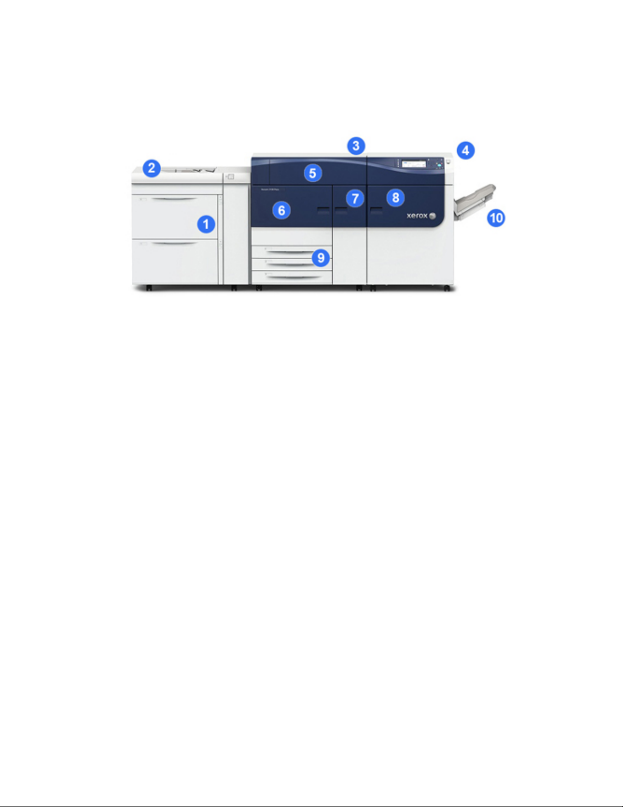
Press Components
1 Oversized High Capacity Feeder (OHCF / Trays 6 and 7)
One OHCF is part of the configuration. The feeder includes two drawers (Trays 6 and
7) that hold 2,000 sheets each. The right portion of the feeder is the J Transport area.
2 Bypass Tray
An optional Bypass tray (Tray 5) can be installed on top of the OHCF to allow for
additional feeding options. Otherwise, the system does not come with this feeding
tray.
3 Print Engine
The press includes the 4 dry ink / toner and drum cartridges, transfer belt and fuser /
ROS system, Full Width Array calibration feature, decurler, registration and paper path,
and paper inverter.
4 Control Panel and Touch Screen
An embedded Control Panel on the top panel of the press consists of buttons, a touch
screen and a keypad for logging on / off, setting job features, printing reports, and
viewing supply, job and press status.
5 Dry Ink / Toner Cover
Open this cover to access and replace the dry ink / toner cartridges.
6 Left Front Door
Open this door to access the registration area and paper handling drawer to clear paper
jams. This area also includes the Transfer Drawer and Xerographic Drawer for replacing
customer replaceable units (CRUs).
Xerox®Versant®2100 Press1-2
User Guide
Page 15

Product Overview
7 Center Front Door
Open this door to access the decurler area and fuser assembly.
8 Right Front Door
Open this Output Module door to access the exit / inverter area, the cooling belt and
full width array.
9 Paper Trays 1, 2, and 3
These internal trays of the print engine feed standard size paper.
10 Offset Catch Tray (OCT)
If there are no inline finishing devices attached to the system, the Offset Catch Tray
can be installed for holding print output.
11 Interface Module
12 High Capacity Stacker
The Interface Module and optional finishing devices, such as the High Capacity
Stacker, are not part of the base configuration.
When the Offset Catch Tray is removed, and any of the optional finishing devices are
attached, the Interface Module is required to provide decurling and paper height
adjustment between the print engine and the attached finishing device.
Locating the Press Serial Number
The press serial number can be accessed from either the press control panel or by locating
the serial number plate on the inside frame of the first feeder tray (Tray 1).
1. Press the Machine Status button on the press control panel.
2. From the Machine Status screen, ensure that the Machine Information tab is
displayed.
The press serial number is displayed under General Information.
3. If there is a loss of power and it is not possible to access the Machine Status screen,
the press serial number can also be found on the inside frame of the press near the
Paper Tray 1 drawer:
a) At the press, fully open Paper Tray 1.
User Guide
1-3Xerox®Versant®2100 Press
Page 16

Product Overview
b) At the left of the feeder tray, on the press frame, locate the plate with the serial
number (SER#).
Status Lights
There are three status lights on the press directly below the Control Panel. From right
to left, they are:
• Main Power Status LED -steady green indicates main power to the system is on
• Error Status LED - steady orange indicates the press is experiencing faults and / or
errors
• Data Transmission Status LED - flashing green indicates that the transmission of an
incoming print job is in process
Control Panel
The embedded Control Panel on the press includes an LCD touch screen, keypad and
feature buttons. The touch screen displays instructions, faults, and informational
messages. Select the Control Panel buttons to log in, perform job setup functions, and
view job, press, and supply statuses.
1 Home button
Displays the main menu. Provides access to view the supplies and trays available on
the press and the status of consumables.
2 Tools button
Displays the Tools mode screen. For the operator, select the Tools icon to view billing
information and to perform press calibration such as Full Width Array color uniformity
adjustments.
3 Job Status button
Use to check the progress of active jobs and detailed information about completed
jobs or pending jobs. This area also allows you to delete a job (cancel printing) and to
pause jobs.
4 Machine Status button
Use to check the press configuration, the software version, the press billing meter and
counter information, and to access and print job history or error reports.
Xerox®Versant®2100 Press1-4
User Guide
Page 17

Product Overview
5 Touch Screen
Directly touch the screen to select and set features. Displays instructional and
informational messages, fault clearance procedures and general press information.
6 Log In / Out button
Use to log in and out of Administrator mode or Authentication mode with user ID and
password.
7 Language button
Use to select a different language for the touch screen options.
8 Power Saver button
Use this button if the press has been inactive and the touch screen is dark (system is
in Energy Saver mode). This button manually exits the system from Energy Saver mode;
it does not place the press in Energy Save mode.
9 Numeric Keypad
Use to enter alphanumeric characters. The ‘C’ Cancel Entry cancels the previous entry
made on the numeric keypad.
10 Clear All button
Use this button to return all selections to the same state as when the press was powered
on. Press once to clear a current entry. Press twice to return to default settings.
11 Stop button
Press to stop and pause the print job in progress.
12 Cancel Entry button
Use this button to cancel the previous entry made on the numeric keypad.
13 Start button
Press to start and print a selected report from the print engine. Also used by the
Customer Service Engineer during diagnostic routine procedures.
14 Press Status Lights
The three indicator lights that identify: data transmission in progress, the press is
experiencing an error, and main power is on.
Logon
There are two logon levels:
• Guest / Operator: This is the default logon user. You are automatically logged on as
Guest.
1-5Xerox®Versant®2100 Press
User Guide
Page 18
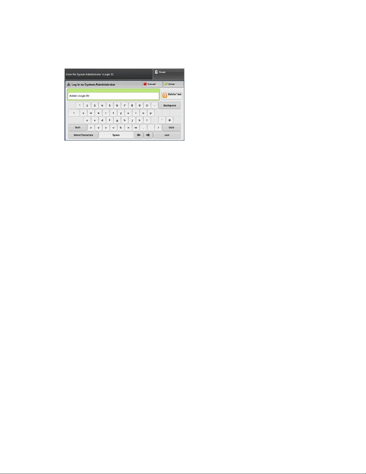
Product Overview
• Administrator: This logon level is required to customize the system and network
defaults for your press and to customize particular print jobs by setting, or changing
parameters for certain features. Press the Guest button (or the Log in button on the
Control Panel) to access the Login screen.
Note
Refer to the System Administration Guide for more information on the Administrator
features.
Language
Note
The number of languages available on your system depends on what was installed during
the initial installation process.
Selecting a particular Language button immediately changes the language. No
confirmation is required.
Changing the Language
1. Press the Language button on the press Control Panel.
The Language window displays on the touch screen.
2. Select the desired language from the list and select Save. The language on the screen
changes to the new language and closes the Language window.
3. Select the Cancel button to return to the main screen.
Energy Saver Mode
The Energy Saver feature allows the press to enter a reduced power consumption mode
when all print jobs have completed and there are no jobs currently processing. There
are two energy saving modes: Low Power and Sleep.
By default, the press automatically enters the Low Power mode after 15 minutes of
inactivity. After 60 minutes of inactivity, the press then enters Sleep mode. These time
intervals for both modes can be changed by the system administrator.
Xerox®Versant®2100 Press1-6
User Guide
Page 19

Product Overview
Here are two examples:
• If Low Power Mode is set to 15 minutes and Sleep Mode is set to 60 minutes, Sleep
Mode activates after 60 minutes of total inactivity, not 60 minutes after Low Power
Mode begins.
• If Low Power Mode is set to 15 minutes and Sleep Mode is set to 20 minutes, Sleep
Mode activates 5 minutes after Low Power Mode begins.
Low Power Mode
In this mode, the power to the Control Panel and fuser unit is lowered to save power.
The display goes out and the Energy Saver button on the Control Panel lights. To use
the press, select the Energy Saver button. The Energy Saver button is no longer lit,
indicating that the Energy Saver feature is canceled.
Sleep Mode
In this mode, the power is lowered more than in the Low Power mode. The display goes
out and the Energy Saver button on the Control Panel lights. To use the press, select the
Energy Saver button. The Energy Saver button is no longer lit, indicating that the Energy
Saver feature is canceled.
Exiting Power Saver Mode
The press exits Power Saver mode either by pressing the Power Saver button on the
press Control Panel or when receiving print data for an incoming job to be printed.
Power On / Off
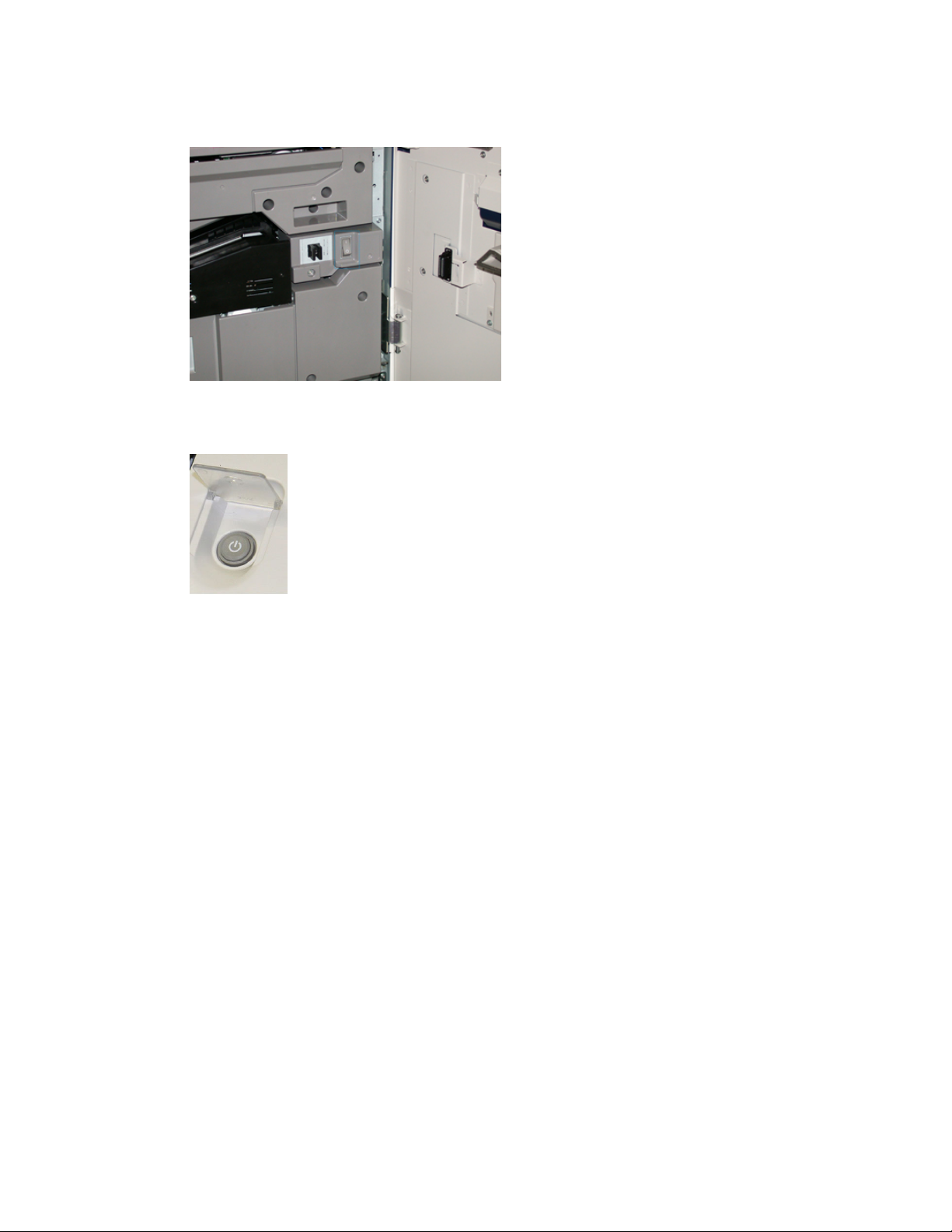
The Power Switches
There are three power switches involved with the press:
• The Breaker switch located at the rear of the press. Initially check to make sure this
switch is set to On when the press is shipped.
User Guide
1-7Xerox®Versant®2100 Press
Page 20
Product Overview
• The Main Power switch located inside the Center Front Door. This switch is used
mainly by the Xerox Service Representative when servicing the press. In rare problem
solving cases, you may be directed to power off the press with this switch.
• The Power On / Off button located on the right side of the Control Panel. This button
is the primary way for you to switch on or off the press. It is used by the operator as
workflow requires.
Use the Power On / Off button to power ON or power OFF the press.
Important
Always use the Power On / Off button first, and then power off the Main Power Switch.
Power On / Off the Press
To switch on the press:
• Check that the Main Power switch behind the Center Front Door is On and then press
the Power On / Off button on top of the print engine to the ON position. The Ready
Indicator light displays green.
A screen message advises of a short wait while the fuser warms up and the press runs
a system check. You can set features for a job during this time and the printing process
will start automatically when the press is ready.
To switch off the press:
• Press the Power On / Off button on the print engine.
Note
Allow the press to remain off for a minimum of 10 seconds before switching on the
power again.
Xerox®Versant®2100 Press1-8
User Guide
Page 21
Product Overview
Feeding and Finishing Devices
Available with your press is a variety of optional feeding and finishing devices. These
devices are briefly introduced on the following pages. Refer to the sections at the end
of this guide for specific information on each feeder or finisher.
Feeding Devices
Oversized High Capacity Feeder (OHCF / Trays 6 and 7)
Tip
The Oversized High Capacity Feeder (OHCF / Trays 6 and 7) are part of the standard
press configuration.
The Oversized High Capacity Feeder (OHCF) contains two trays, Trays 6 and 7 and feeds
a variety of stock sizes, including standard, heavyweight, and oversized stocks up to 13
x 19.2 in. / 330 x 488 mm in size and weighing between 52 gsm and 350 gsm. Each tray
holds 2,000 sheets of coated and uncoated stock.
Chained Oversized High Capacity Feeder (OHCF / Trays 8 and 9)
A second, chained Oversized High Capacity Feeder (OHCF) may be added to the system
to extend the paper capacities by providing two additional trays. This second, chained
OHCF is referred to as Trays 8 and 9, and it feeds a variety of stock sizes, including
standard, heavyweight, and oversized stocks up to 13 x 19.2 in. / 330 x 488 mm in size
and weighing between 52 gsm and 350 gsm. Each tray holds 2,000 sheets of coated
and uncoated stock.
1-9Xerox®Versant®2100 Press
User Guide
Page 22

Product Overview
Bypass (Tray 5)
The Bypass Tray, also called Tray 5, is an optional feeding device that is installed on top
of the Oversized High Capacity Feeder.
Important
When the system configuration includes only one OHCF (Trays 6 and 7), then the Bypass
Tray is installed on top of it. If the system configuration includes an second, chained
OHCF (Trays 8 and 9), then the Bypass Tray is installed on top of the second OHCF (Trays
8 and 9).
The Bypass Tray accommodates a weight range of 52 to 300 gsm and media size of
3.86 x 5.75 inches (98 x 146 mm) to 13 x 19.2 inches (330.2 x 488 mm). The Bypass
Tray holds a maximum of 280 sheets of 20 lb. / 75 gsm plain paper.
The Bypass Tray accepts envelopes, postcards and transparencies.
Finishing Devices
Offset Catch Tray (OCT)
The Offset Catch Tray installed at the end of the print engine receives the completed
print job. Output print sheets can be offset for easy separation. The maximum capacity
of the tray is 500 sheets of 24 lb. (90 gsm) paper.
Interface Module
Important
The Interface Module is required with any inline finishing devices installed with the
system.
Xerox®Versant®2100 Press1-10
User Guide
Page 23
Product Overview
The Interface Module provides communication, an aligned paper path between the
print engine and the attached finishing device, and cooling and decurling of the paper
as it exits the print engine.
GBC®AdvancedPunch
™
The GBC AdvancedPunch may be attached to a variety of optional finishing accessories.
It provides another level of finishing by allowing you to punch holes in 8.5 x 11 in. / A4
documents that support a variety of binding styles. Punch types include 19-hole to a
maximum of 32-hole for 8.5 x 11 in. media. A4 media supports punch types 21-hole to
a maximum of 47-hole.
GBC®AdvancedPunch™Pro
The GBC AdvancedPunch Pro may be attached to a variety of optional finishing
accessories and provides all the same capabilities as the GBC AdvancedPunch.
User Guide
1-11Xerox®Versant®2100 Press
Page 24
Product Overview
The AdvancedPunch Pro also provides additional capabilities such as the following:
• A bigger range of media sizes and types
• LEF and SEF punching
• 2-up punching (double punch) on large sheets
• Quick-change die sets that can be interchanged without any tools
• All die sets include an Identification Label providing the user with the hole pattern
and name
Information on this device can be found later in this guide. Information can also be
found on the customer documentation CD that came with the accessory, or it can be
downloaded from www.xerox.com.
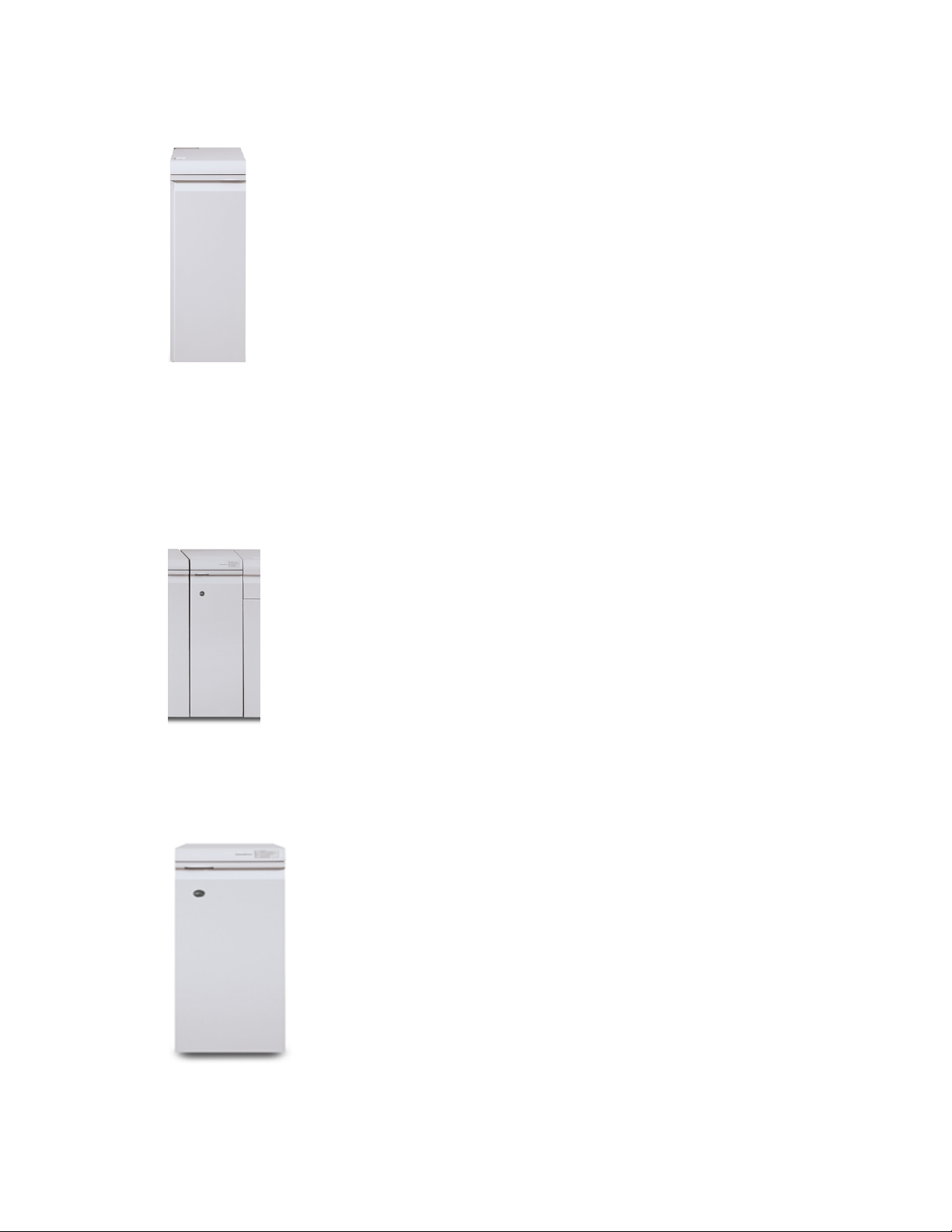
High Capacity Stacker
The High Capacity Stacker (HCS) is an optional finishing device that provides production
stacking and offsetting capabilities of up to 5,000 sheets to a cart in the Stacker Tray.
Shorter runs of up to 500 sheets can be sent to the stacker’s Top Tray.
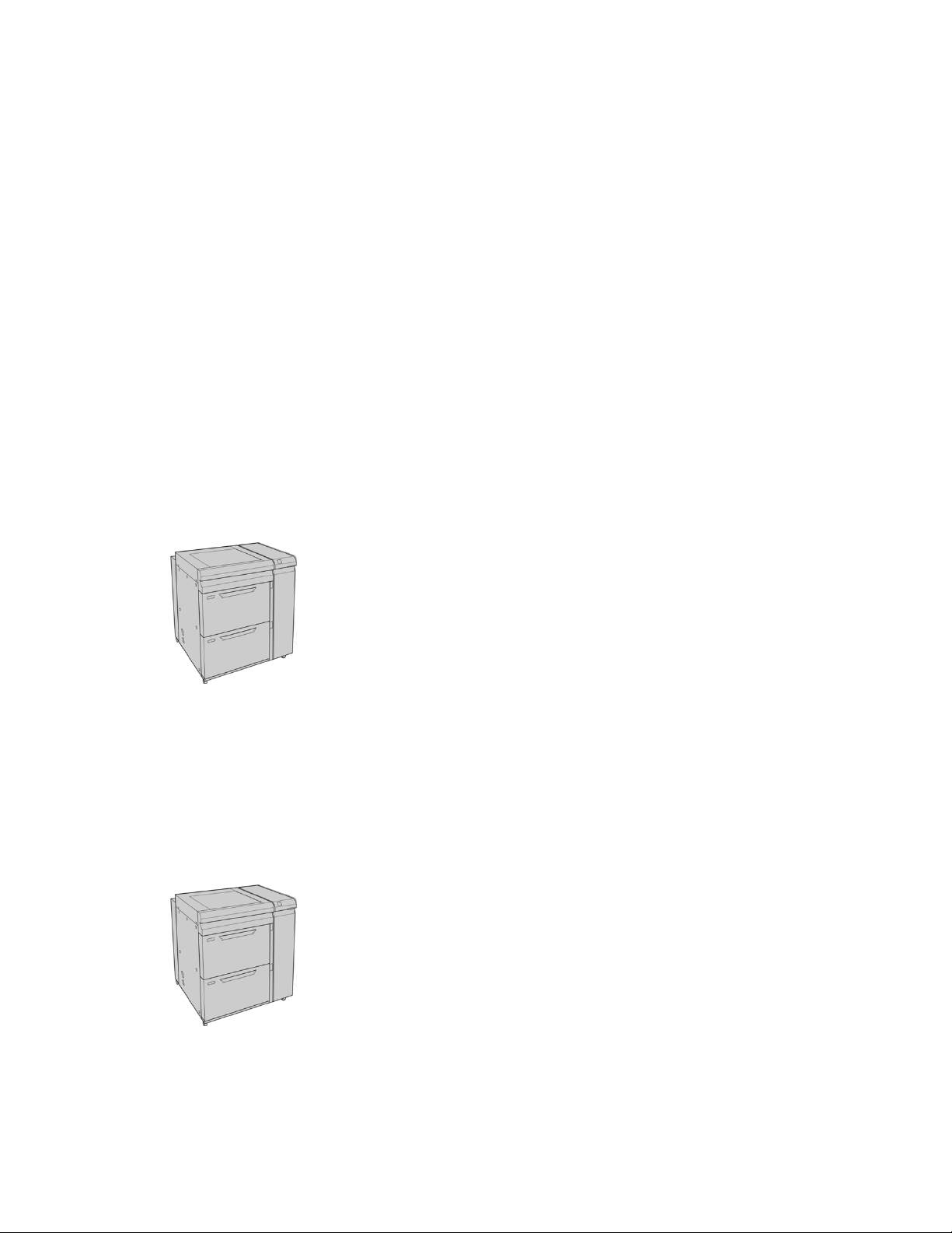
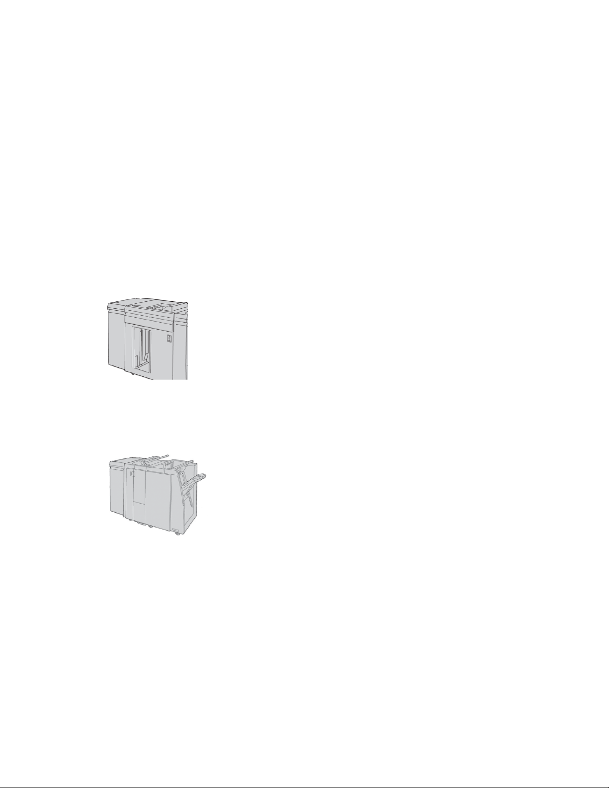
Standard Finisher
This finisher provides a wide range of finishing / folding options. It includes a basic inline
punch, stapler, built-in decurler and interposer.
Note
The Standard Finisher is shown here with the required Interface Module and with the
optional C / Z Folder.
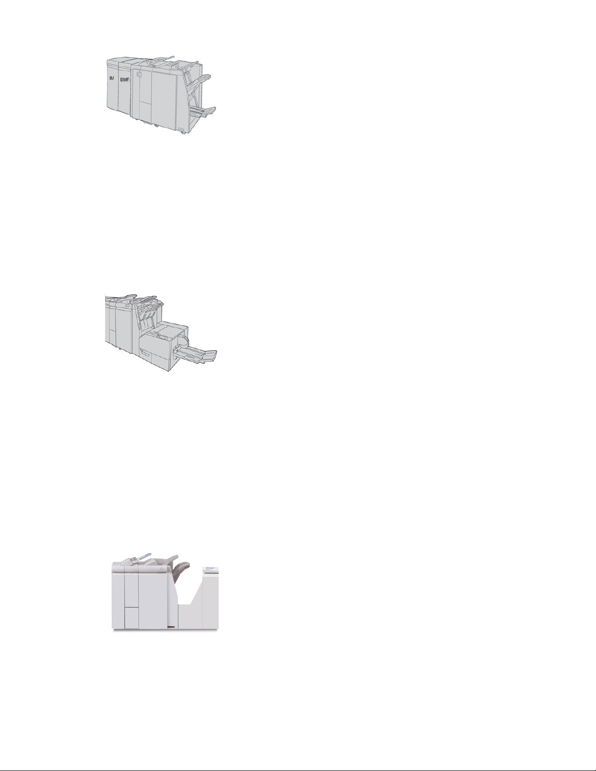
Booklet Maker Finisher
This finisher provides a wide range of finishing/folding options that include a basic inline
punch, stapler, a booklet unit with saddle-stitching and bifold finishing.
Xerox®Versant®2100 Press1-12
User Guide
Page 25
Product Overview
Note
The Booklet Maker Finisher is shown here with the required Interface Module to the left
and the optional C / Z Folder and GBC finisher to the right.
SquareFold®Trimmer Module
The SquareFold Trimmer Module is an optional finishing device that is used in conjunction
with a finishing device that contains a booklet maker (with or without the C / Z Folder).
The SquareFold Trimmer Module flattens the spine of the booklet and trims the face of
the booklet.
Note
The SquareFold Trimmer Module is shown here with the required Interface Module and
the required Booklet Maker Finisher.
Standard Finisher Plus
The Standard Finisher Plus includes the same features and functions as the Standard
Finisher but also serves as an interface to transfer paper between the print engine and
any third-party, Document Finishing Architecture (DFA) device attached to the press.
Note
The Standard Finisher Plus requires the Interface Module.
User Guide
1-13Xerox®Versant®2100 Press
Page 26

Product Overview
Third-Party Finishing Devices
Additional third-party, Document Finishing Architecture (DFA) devices are also available
for your press. Information on these DFA devices can be obtained by contacting your
Xerox sales representative.
Xerox®Versant®2100 Press1-14
User Guide
Page 27

2
Where to Find Help
Help on the Xerox Web Site
For technical product support, Xerox supplies, customer documentation, and answers to
frequently-asked questions, go to www.xerox.com. You will find the latest documentation
and the knowledge base under Support & Drivers. Use the Contact link for specific
contact information / telephone numbers in your area.
Note
Be sure to periodically check this website for the latest information on your product.
It may be helpful to know your press serial number before calling for support. The press
serial number is shown on the Machine Information tab: Machine Status > Machine
Information.
Diagnostic Tool
A Customer Diagnostic Tool CD is provided with your system. It provides you with the
information needed to identify and resolve image quality issues or faults the press may
be experiencing, and includes the procedures on how to replace customer-accessible
press components.
This tool is the first step you can use in isolating a problem or specific fault code and
the resolution associated with it.
2-1Xerox®Versant®2100 Press
User Guide
Page 28
Where to Find Help
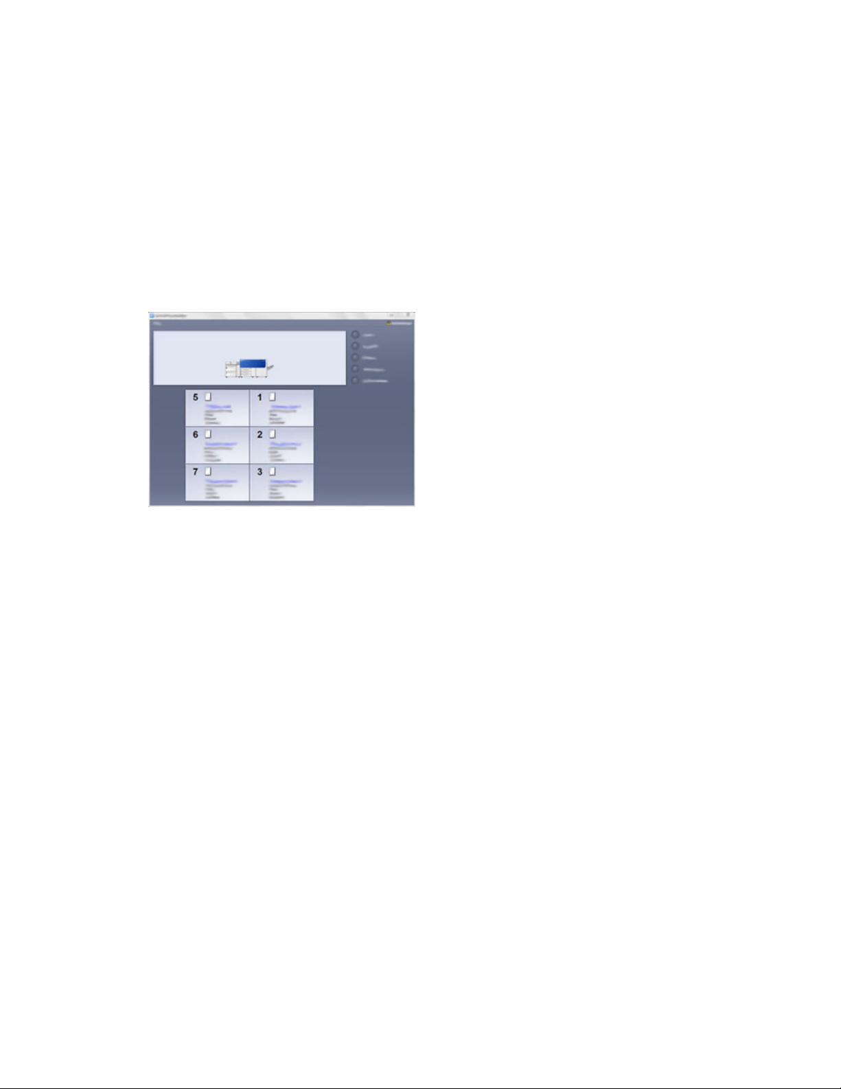
Stock Library Manager Online Help
At the top of the print server window contains a Help area from which you can locate
information on how to use the print server’s job and print management features.
There is also Help from within the Stock Library Manager application on the print server.
Use this Online Help to learn how to manage stocks used by the press and to select
advanced settings that resolve paper curl, offsetting, paper misfeeds, registration and
fold adjustments.
From the Stock Library Manager window, select Help from the top left of the screen. An
About menu and Help menu are available:
• Select the About menu to learn the software version installed.
• Select the Help menu to access all of the Stock Library Help topics such as Tray
Properties, Stock information, how to add stock, and more.
In the Contents area, topics are displayed to the right of the book icons. Selecting a
book icon expands the view and provides selections to subtopics. The right and left arrow
buttons advance forward or backward one topic at a time using the same order as
displayed on the Contents tab.
Print Server Customer Documentation
• The FreeFlow Print Server features are documented in the Online Help system from
the Help menu shown on the main print server window. Additional FreeFlow Print
Server user documentation can be found at www.xerox.com.
• The EFI Print Server Help menu on the Command WorkStation window is designed
to provide information on specific work flows when using the Command WorkStation.
Additional user documentation supplied by EFI is available to you from www.xerox.com
under the Support and Drivers link.
Xerox®Versant®2100 Press2-2
User Guide
Page 29

3
Technical Specifications
Press Specifications
Rated Speed
100 pages per minute of Letter (8.5 x 11 in.) / A4 paper size (full color or black only)
Print Modes
Two print modes are supported and are specified at the print server:
• 4 Color Mode (CMYK)
• Black and White Mode (Greyscale)
Maximum Printable Area
• Default Border: 2 mm on all sides
• Adjustable Border: 0.5 mm up to 400 mm on all sides
• Print Image Quality Assurance Area: 12.48 x 18.98 in. / 317 mm x 482 mm
• For Trays 1, 2 or 3: 12.72 x 18.98 in. / 323 x 482 mm
• Bypass (Tray 5): 12.83 x 18.98 in. / 326 x 482 mm
• For the OHCF (Trays 6 and 7): 12.83 x 18.98 in. / 326 x 482 mm
Paper Size Ranges
• Minimum:
- Trays 1-3: 5.51 x 7.17 in. / 140 x 182 mm
- Bypass (Tray 5): 3.86 x 5.75 in. / 98 x 146 mm
- Trays 6 and 7: 3.86 x 5.75 in. / 98 x 146 mm
• Maximum:
- Trays 1-3: 13 x 19.2 in. / 330.2 x 488 mm
User Guide
3-1Xerox®Versant®2100 Press
Page 30

Technical Specifications
- Bypass (Tray 5): 13 x 19.2 in. / 330.2 x 488 mm
- Trays 6 and 7: 13 x 19.2 in. / 330.2 x 488 mm
Printing Resolution
• Print Engine Imaging Resolution: 2400 x 2400 dpi
• Print Server RIP Resolution (print server to print engine): 1200 x 1200 dpi
First Print: Out Time
First Print: Out Time is the minimum time from when the press receives a job from the
print server to the time when the trail edge of the first print passes through the press
exit sensor.
From standby mode, the system usually takes less than 1 minute to the start printing
• From a cold start (power on or power saver), the system takes less than 5 minutes to
start printing
Press Warmup Time
The press warmup times vary depending on the current state / mode of the press. Warmup
times are listed as follows:
• From a cold start (either power on or power saver mode), less than 5 minutes
• From Sleep Mode / Power Saver, less than 5 minutes
• From Standby Mode, less than 1 minute
• When switching print modes (such as from black only to full color), approximately 2
minutes
Paper Tray Information
Trays 1, 2 and 3
When the press is first installed, the tray size setting for Trays 1 and 3 are set at 8.5 x
11 inches or A4 (LEF). The tray size setting for Tray 2 is set at 11 x 17 inches or A3 (SEF).
When the Stock Library Manager is installed on the print server, the default for all trays
is Letter (8.5 x 11 inches). At the Stock Library Manager, the operator can then set those
trays to different stock size settings.
The specifications for each tray are:
• Maximum of 550 sheets of 24 lb. (90 gsm) uncoated paper; 28-80 lb. cover (105-120
gsm) coated stock
• Paper weight range of 18 lb. Bond to 95 lb. Cover (64 gsm to 256 gsm)
• Paper sizes starting at 5.51 x 7.17 in. / 140 x 182 mm to a maximum of 13 x 19.2 in.
/ 330.2 x 488 mm
Xerox®Versant®2100 Press3-2
User Guide
Page 31

Technical Specifications
• Stock types include transparencies, heavyweight, coated and uncoated, predrilled,
and tabs
• Loading paper Long Edge Feed (LEF) / portrait or Short Edge Feed (SEF) / landscape
(dependent on the actual paper size)
• Auto size detection capability
• Automatically adjusts the tray position in the front and back based on the paper size;
this is done once the tray is closed
Oversized High Capacity Feeder (Trays 6 and 7)
The specifications for each tray are:
• Maximum of 2,000 sheets of 24 lb. (90 gsm) uncoated paper; 2,100 sheets of 82 gsm
and 2,300 sheets of 64 gsm
• Paper weight range of 52 to 350 gsm
• Stock types include transparencies, heavyweight, coated and uncoated, predrilled,
and tabs. Transparencies perform best when printed from Trays 6 and 7
• If using the optional Postcard bracket, minimum size is 4 x 6 inches / 101.6 x 152.4
mm
Note
For more information on the optional Postcard bracket, refer to the Paper and Media
section of this guide.
Bypass (Tray 5)
• Maximum of 250 sheets of 24 lb. (90 gsm) uncoated paper; 28 lb. to 110 lb. cover
(106-300 gsm) coated stock
• Paper weight range of 52 gsm (uncoated) to 300 gsm (coated)
• Stock types include transparencies, heavyweight, coated and uncoated, predrilled,
and tabs
Throughput / Productivity Information
Process and print speed is based on simplex (1-Sided) / duplex (2-Sided) mode, paper
type, paper weight, paper size and feeding tray.
Table 1: Trays 1, 2 and 3 in LEF Feed Direction
Prints Per MinuteSimplex / DuplexPaper WeightPaper Type
100 ppm / 50 ppmSimplex / Duplex64 to 256 gsm8.5 x 11 / A4 uncoated
and coated
and Transparencies
User Guide
40 ppmSimplex106 to 256 gsm8.5 x 11 / A4 Labels
3-3Xerox®Versant®2100 Press
Page 32

Technical Specifications
coated and coated
coated and coated
Table 2: Trays 1, 2 and 3 in SEF Feed Direction
coated
coated
and coated
Prints Per MinuteSimplex / DuplexPaper WeightPaper Type
80 ppmSimplex106 to 176 gsm8.5 x 11 / A4 Tab un-
80 ppmSimplex177 to 256 gsm8.5 x 11 / A4 Tab un-
Prints Per MinuteSimplex / DuplexPaper WeightPaper Type
80 ppm / 40 ppmSimplex / Duplex64 to 256 gsm8.5 x 11 uncoated and
60 ppm / 30 ppmSimplex / Duplex64 to 256 gsmA4 uncoated and
60 ppm / 30 ppmSimplex / Duplex64 to 256 gsm8.5 x 14 / B4 uncoated
and coated
coated and coated
uncoated
and Transparencies
and Transparencies
Table 3: Bypass (Tray 5)
148 mm
coated and coated
52 ppm / 26 ppmSimplex / Duplex64 to 256 gsm11 x 17 / A3 uncoated
50 ppm / 24 ppmSimplex / Duplex64 to 256 gsm12 x 18 / SRA3 un-
50 ppm / 24 ppmSimplex / Duplex64 to 256 gsm13 x 19.2 coated and
32 ppmSimplex106 to 256 gsm8.5 x 11 / A4 Labels
25 ppmSimplex106 to 256 gsm8.5 x 14 / B4 Labels
Prints Per MinuteSimplex / DuplexPaper WeightFeedDirectionPaper Type
70 ppm / 35 ppmSimplex / Duplex52 to 300 gsmPostal card 148 x
70 ppm / 35 ppmSimplex / Duplex52 to 300 gsmLEF8.5 x 11 / A4 un-
and coated
coated
60 ppm / 30 ppmSimplex / Duplex52 to 300 gsmSEF8.5 x 11 uncoated
50 ppm/ 25 ppmSimplex / Duplex52 to 300 gsmSEFA4 uncoated and
Xerox®Versant®2100 Press3-4
User Guide
Page 33

Technical Specifications
Prints Per MinuteSimplex / DuplexPaper WeightFeedDirectionPaper Type
50 ppm / 25 ppmSimplex / Duplex52 to 300 gsmSEF8.5 x 14 / B4 un-
coated and coated
44 ppm / 22 ppmSimplex / Duplex52 to 300 gsmSEF11 x17 / A3 un-
coated and coated
41 ppm / 21 ppmSimplex / Duplex52 to 300 gsmSEF12 x 18 / SRA3
coated and uncoated
40 ppm / 20 ppmSimplex / Duplex52 to 300 gsmSEF13x19.2coatedand
uncoated
Paper Specifications for Trays 1-3, 5, and 6-7
Note
Always refer to the Recommended Media List (RML) for a comprehensive list of supported
media. The RML can be accessed from the Stock Library Manager application, and can
also be downloaded from http://www.xerox.com/.
User Guide
3-5Xerox®Versant®2100 Press
Page 34

Technical Specifications
Weight (gsm)TraysPaper SizePaper Type
Plain paper (coated & uncoated)
Drilled paper (coated & uncoated)
B5 SEF / LEF
A4 SEF / LEF
A4 Cover SEF / LEF
DT Special A4 SEF / LEF
B4 SEF
A3 SEF
SRA3 SEF
DT Special A3 SEF
4 x 6 in. SEF
7.25 x 10.5 in. SEF / LEF
8 x 10 in. SEF / LEF
8.46 x 12.4 in. SEF
8.5 x 11 in. SEF/LEF
8.5 x 13 in. SEF / LEF
8.5 x 14 in. SEF
9 x 11 in. SEF / LEF
11 x 15 in. SEF
11 x 17 in. SEF
12 x 18 in. SEF
12.6 x 19.2 in. SEF
13 x 18 in. SEF
16-kai (TFX) SEF / LEF
16-kai (GCO) SEF / LEF
Pa-kai (TFX) SEF
pa-kai (GCO) SEF
Trays 1 - 3
Trays 5, 6 and 7
52 to 256
52 to 350
coated)
Embossed (coated & uncoated)
Government-Legal SEF / LEF
DT Special A4 SEF / LEF
DT Special A3 SEF
Envelopes
8.5 x 13 in.
215.9 x 330.2 mm
8.90 x 12.20 in.
226.0 x 310.0 mm
12.20 x 17.00 in.
310.0 x 432.0 mm
Square SEF / LEF
8.5 x 11 in. / A4 LEFLabels (coated & uncoated)
Trays 1 - 3
Trays 5, 6 and 7
Trays 5, 6 and 7
Trays 5, 6 and 7
Trays 5, 6 and 7
Trays 5, 6 and 7rectangle 3 x 10 SEF
Trays 1 - 3
Trays 5, 6 and 7
64 to 105All TraysRecycled paper (coated & un-
106 to 256
106 to 350
---All Trays8.5 x 11 in. (A4) LEFTransparency
106 to 350Trays 5, 6 and 7Postcard (coated and uncoated)
---Trays 1 -3
---Trays 1 -3
---Trays 1 -3
106 to 256
106 to 350
Xerox®Versant®2100 Press3-6
User Guide
Page 35

Technical Specifications
Weight (gsm)TraysPaper SizePaper Type
163All Trays9 x 11 in. LEFTabbed Inserts
Press Environmental Specifications
The press enters the Power Saver mode after 15 minutes of inactivity on the press. The
factory default time of 15 minutes can be changed when logged on as the Administrator.
For more information, refer to the System Administration Guide.
The temperature and relative humidity of the room where the press is located must be
within the minimum and maximum allowable temperature and relative humidity limits
for the press system to operate correctly.
Ambient Temperature
The operating temperature range is 10° to 32° Celsius (50° F to 90° F)
Relative Humidity
The required humidity range is 15% to 85% (relative humidity) - (RH) J zone (Dew
condensation is inhibited)
Altitude
The press functions at the elevation of 0 to 2,500 meters (0 to 8,200 feet)
User Guide
3-7Xerox®Versant®2100 Press
Page 36

Technical Specifications
Xerox®Versant®2100 Press3-8
User Guide
Page 37

4
Paper and Other Media
Paper and Other Media Overview
This section describes how to load specific stocks into the various feeder trays.
Before loading paper, consider the following:
• To define attributes for a stock, add a new stock to the Stock Library, or assign a stock
to a paper tray for the print job, access the Stock Library Manager on the print server.
If you have restricted access, contact your System Administrator.
Note
The Stock Library Manager is an application that is loaded onto the print server and
is used to manage the stocks and paper trays for your press. By default, the Stock
Library feature is available to both the operator and system administrator modes.
Your System Administrator may restrict user access to change or add stocks. When
you are loading paper, the Stock Library Manager application opens the Tray
Properties window for that tray and you can view or change the stock assigned to
that tray.
• The press supports the ability to pull different stock sizes and paper types from various
trays and assemble them as part of a single job. To select multiple paper trays and
insert different papers within one job, program this custom job at the print server
using features such as special pages.
• The press supports Automatic Tray Switching, which allows a job to switch
automatically from an empty tray to a full tray containing the same size paper,
orientation and stock type. Refer to the System Administrator Guide for how to enable
this feature and prioritize the order of trays to search on and use.
4-1Xerox®Versant®2100 Press
User Guide
Page 38

Paper and Other Media
Loading Media in Trays 1, 2, and 3
Trays 1, 2, and 3 are identical. Each tray has a capacity of 550 sheets of 20 lb. / 75 gsm
paper. Stock can be LEF or SEF, landscape or portrait.
Note
Each feeder tray has a stock loading label. When loading media into the tray, refer to
the labels on the inside panel of the feeder tray for the correct orientation of that stock
type.
Loading Paper in Trays 1, 2, and 3
From the Stock Library Manager on the print server, set the stock type, weight and size
settings for the tray. At the press, check that the stock loaded in the paper tray matches
the paper tray attributes programmed.
Note
A paper jam may occur if a tray is opened while it is being used to feed stock.
1. Select the appropriate paper stock for your print job.
2. Pull out the tray slowly until it stops.
3. Open the ream of paper with the seam side facing up.
4. Fan the sheets before loading them into the tray.
5. Load and align the edge of the paper against the left edge of the tray.
Paper can be loaded either in the LEF / portrait or SEF / landscape direction.
6. Adjust the paper guides by pressing in the guide release and carefully moving the
Edge Guide until it lightly touches the edge of the material in the tray.
Do not load materials above the MAX line located on the rear Edge Guide.
7. Gently push in the tray until it comes to a stop.
The Paper Tray Properties window displays on the print server (on Stock Library
Manager). You can view and set stock attributes and verify trays are assigned with
the correct stock. The Stock Library Manager is available from the print server only
and not at the press.
Xerox®Versant®2100 Press4-2
User Guide
Page 39

Paper and Other Media
8. From the Tray Properties window, enter or verify the correct paper information,
including size, type, weight and, if necessary, paper curl and / or alignment option.
Select the stock and assign the stock to the tray to be used.
9. Select OK to save the information and close the Tray Properties window.
Loading Tab Stock in Trays 1, 2, and 3
You can load either single straight collated or single reverse collated tab stock.
Before loading tab stock in paper trays 1, 2 or 3, you need to program your tab job at
the Stock Library Manager application on the print server. Create a new tab stock name
and select these tab-specific property settings for the tab print job:
• Type - Precut Tabs or Tab Stock
• Modules - the number of tabs in the set
• Paper Size - Auto Select or custom size of 9 x 11 inches
• Weight - select the correct tab stock weight in the range 106 to 176 gsm
• Tray / Source - Tray 1, 2 or 3
• Print Output Order / Tab Sequence - N to 1
• Output Delivery - Face Up
Note
Refer to the print server documentation for more detailed information on how to set up
a tab job at your print server.
Note
If a jam occurs while running tabbed sets, cancel the job and start again.
1. After programming your tab job at the print server, select the appropriate and
matching tab stock for your print job.
2. Pull out the tray slowly until it stops.
3. Fan the tab stock before loading into the tray.
4. Load the tab stock LEF (portrait) and align the straight edge of the tab stock against
the left edge of the tray (tabs to the right or trailing edge). For single straight collated
tabs, the first blank tab cutout in the stack will be toward the rear of the tray. For
single reverse collated tabs, the first blank tab cutout in the stack will be toward the
front of the tray.
Note
Tab stock is loaded so the straight edge of the stock is in the feed direction. Also, you
can only load the tab stock LEF.
User Guide
4-3Xerox®Versant®2100 Press
Page 40

Paper and Other Media
5. Adjust the paper guides by pressing in the guide release and carefully moving the
Edge Guide until it lightly touches the edge of the stock in the tray.
Do not load materials above the MAX line located on the rear Edge Guide.
6. Gently push in the tray until it comes to a stop.
7. If the Tray Properties window displays on the print server, confirm the correct tray
to which it is printing and other information, including size (9 x 11 inches), type (precut
tab), and, if necessary, paper curl and / or alignment option.
8. Select OK to save the information and close the Tray Properties window.
Loading Transparencies in Trays 1, 2, and 3
Note
Do not use transparencies with the white side strip (either permanent or removable)
At the Stock Library Manager, make sure to select Transparency as the Paper or Media
Type and select the tray containing the transparencies as the Paper Source.
1. Select the appropriate paper stock for your print job.
2. Pull out the tray slowly until it stops.
3. Fan the transparencies to stop them from sticking together before loading into the
tray.
4. Load a small stack of paper into the tray first. The paper must be the same size as
the transparencies.
5. Load the transparencies LEF on top of this paper stack. Align the edge of the
transparencies with a removable stripe against the left edge of the tray, with the side
to be printed on facing down.
Note
• Do not mix paper and transparencies in a tray. Jams may occur.
• Do not load more than 100 transparencies in a paper tray at one time.
• Load 8.5 x 11 in (A4) transparencies long edge feed only (landscape).
6. Adjust the paper guides by pressing in the guide release and carefully moving the
Edge Guide until it lightly touches the edge of the material in the tray.
Do not load materials above the MAX line located on the rear Edge Guide.
7. Gently push in the tray until it comes to a stop.
If enabled by your System Administrator, the Paper Tray Properties window displays
on the Stock Library Manager on the print server. The Stock Library Manager is not
available at the press.
Xerox®Versant®2100 Press4-4
User Guide
Page 41

Paper and Other Media
8. From the Tray Properties window, enter the correct paper information, including size,
type, weight and, if necessary, paper curl and / or alignment option.
9. Select OK to save the information and close the Tray Properties window.
Loading Pre-drilled Stock in Trays 1, 2, and 3
Pre-drilled paper is defined as having two or more holes along one edge for use in ring
binders and notebooks. To prevent jams or damage, make sure that any plugs (pieces
cut out of the paper to create the holes) do not remain in the stack.
1. Select the appropriate paper stock for your print job.
2. Pull out the tray slowly until it stops.
3. Open the ream of paper with the seam side facing up.
4. Fan the sheets before loading them into the tray.
5. Load and align the edge of the pre-drilled paper with the holes against the left edge
of the tray.
Paper can be loaded either in the LEF / portrait or SEF / landscape direction.
6. Adjust the paper guides by pressing in the guide release and carefully moving the
Edge Guide until it lightly touches the edge of the material in the tray.
Do not load materials above the MAX line located on the rear Edge Guide.
7. Gently push in the tray until it comes to a stop.
If enabled by your System Administrator, the Paper Tray Properties window displays
from the Stock Library Manager on the print server. The Stock Library Manager is not
available at the press.
8. From the Tray Properties window, enter the correct paper information, including size,
type, weight and, if necessary, paper curl and / or alignment option.
9. Select OK to save the information and close the Tray Properties window.
Loading Media in the Bypass (Tray 5)
Note
The Bypass Tray is located on the top of the OHCF (either Trays 6 / 7 or optional Trays
8 / 9).
User Guide
4-5Xerox®Versant®2100 Press
Page 42

Paper and Other Media
This tray is used primarily when using a small quantity and special media (such as
envelopes). When using the Bypass (Tray 5), refer to the following information:
• Program the stock job properties at the Stock Library Manager on the print server.
• You can load up to 280 sheets of 20 lb. / 75 gsm paper.
• Do not load mixed-size paper into the Bypass tray.
• Do not load materials above the MAX line as indicated on the tray.
Loading Paper in the Bypass (Tray 5)
1. Gently extend the Bypass (Tray 5) as necessary to accommodate the paper.
2. Hold the center of the paper guides and slide them to the desired paper size.
3. Select the appropriate paper stock for your print job.
4. Open the ream of paper with the seam side facing up.
5. Fan the sheets before loading them into the tray.
6. Insert the paper or media into the tray until it stops.
7. Adjust the paper guides so that they touch the edges of the stack.
The Paper Tray Properties window displays on the Stock Library Manager on the
print server. The Stock Library Manager is not available at the press.
8. From the Tray Properties window, verify that the correct paper information such as
size, type and weight are selected and match the stock loaded in the tray.
9. Select OK to save the information and close the Tray Properties window.
Loading Tab Stock in the Bypass (Tray 5)
You can load either single straight collated or single reverse collated tab stock.
Xerox®Versant®2100 Press4-6
User Guide
Page 43

Paper and Other Media
Before inserting tab stock in the Bypass Tray, program your tab job at the Stock Library
Manager application on the print server. Create a new tab stock name and select these
tab-specific property settings for the tab print job:
• Type - Precut Tabs or Tab Stock
• Modules - the number of tabs in the set
• Paper Size - Auto Select or Custom Size of 9 x 11 inches
• Weight - select the correct tab stock weight in the range 106 to 176 gsm
• Tray / Source - Tray 5
• Print Output Order / Tab Sequence - 1 to N
• Output Delivery - Face Down
Note
Refer to the print server documentation for more information on how to set up a tab
job at your print server.
Note
If a jam occurs while running tabbed sets, cancel the job and start again.
1. After programming your tab job at the print server, select the appropriate and
matching tab stock for your print job.
2. Locate the Bypass (Tray 5) on top of the OHCF.
3. Hold the center of the paper guides and slide them to the desired stock size.
4. Fan the tab paper before inserting into the tray.
5. Insert the tab stock into the tray so the straight edge of the stock is in the feed
direction (lead edge) and the tabs are to the left (trail edge).
6. Continue to insert the tab stock into the tray until it stops.
7. Adjust the paper guides so that they touch the edges of the stack.
Loading Transparencies in the Bypass (Tray 5)
Note
Do not use transparencies with a white side strip (either permanent or removable).
At the Stock Library Manager, make sure to select Transparency as the Paper or Media
Type and select the tray containing the transparencies as the Paper Source.
1. Gently extend the Bypass (Tray 5) as necessary to accommodate the paper.
2. Hold the center of the paper guides and slide them to the desired paper size.
3. Select the appropriate paper stock for your print job.
4. Fan the transparencies to stop them from sticking together before loading into the
tray.
5. Insert the transparencies LEF into the tray with the side to be printed on face up and
with the removable stripe to the right.
6. Continue to insert the paper or media into the tray until it stops.
7. Adjust the paper guides so that they touch the edges of the stack.
4-7Xerox®Versant®2100 Press
User Guide
Page 44

Paper and Other Media
Loading Pre-drilled Stock in the Bypass (Tray 5)
1. Gently extend the Bypass (Tray 5) as necessary to accommodate the paper.
2. Hold the center of the paper guides and slide them to the desired paper size.
3. Select the appropriate paper stock for your print job.
4. Fan the sheets before loading them into the tray.
5. Insert the pre-drilled stock into the tray in the LEF direction with the holes to the
right.
6. Continue to insert the paper or media into the tray until it stops.
7. Adjust the paper guides so that they touch the edges of the stack.
Loading Envelopes in the Bypass (Tray 5)
Note
It is recommended that you print envelopes from the Bypass (Tray 5) only. Trays 6 and
7 can be used if the Postcard Bracket is mounted and the stack height is limited to no
more than 200 envelopes.
When setting up your print job, follow the steps below to define the custom paper settings
at the Tray Properties window and assign this stock to Tray 5. With the flap closed,
measure the height and width of the envelope.
The following envelope sizes are supported. Other sizes can be used but performance is
not guaranteed.
• C4 (229 x 324 mm) Short Edge Feed (SEF) or Long Edge Feed (LEF)
• C5 (162 x 229 mm) Short Edge Feed or Long Edge Feed
• #10 (4.125 x 9.5 inches) Short Edge Feed
1. Always load envelopes with the flaps closed.
Do not use padded envelopes.
2. When loading in the SEF direction, place the flaps facing the back of the press. When
loading in the LEF direction, place the flaps facing the lead edge.
3. When submitting your print file, select Custom Paper as the Paper Type. Enter the
dimensions of the envelope.
The width is measured from the lead edge to the trail edge of the envelope. For
example, if you are loading SEF, enter the long dimension of the envelope as the
width. If you are loading the envelope LEF, enter the short dimension of the envelope
as the width.
4. Enter a heavy paper weight value, such as 220 gsm, in the Paper Weight field.
5. Select the Bypass Tray as the Paper Source.
6. Store unused envelopes in their original packaging to avoid the excess moisture or
dryness that can affect print quality and cause wrinkling. Excessive moisture can
cause the envelopes to seal before or during printing.
Xerox®Versant®2100 Press4-8
User Guide
Page 45

Paper and Other Media
Some wrinkling or embossing may occur when printing on envelopes. Successful envelope
printing depends on the quality and construction of the envelopes. Tryanother envelope
brand if problems occur.
Loading Media in the OHCF (Trays 6 and
7)
Note
Each feeder tray has a stock loading label. When loading media into the tray, refer to
the labels on the inside panel of the feeder tray for the correct orientation of that stock
type.
Note
It is recommended that you use the Bypass (Tray 5) to feed envelopes. However, if you
use Trays 6 or 7, C5 and #10 envelopes must be fed SEF with the Postcard Bracket
installed. Stack height is limited to 200 envelopes.
Postcard Bracket
The Postcard bracket is delivered with the OHCF from manufacturing. The Postcard
bracket allows you to print on smaller size media without requiring post-processing
cutting or sorting. The Postcard bracket specifically accommodates 4 x 6 in. (101.6 x
152.4 mm) SEF media.
Using the Postcard Bracket
Use the following procedure for installing and using the Postcard Bracket when printing
on smaller media (4 x 6 in. / 101.6 x 152.4 mm).
With the Postcard Bracket installed, you can print envelopes from Trays 6 and 7. The
stack height is up to 200 envelopes.
1. Slowly open one of the paper trays until it stops and remove the paper.
User Guide
4-9Xerox®Versant®2100 Press
Page 46

Paper and Other Media
2. Move the paper guides out to their largest position.
3. Open the front cover of the OHCF.
4. Remove the Postcard Bracket from inside the OHCF front cover.
5. Install the Postcard Bracket so that it sits on the locating pins on the upper frame
and in the grooves on the bottom of the tray.
6. Tighten the thumb screw so it locks the Postcard Bracket in place.
7. Load the postcard stock and adjust the paper guides against the stock.
8. Close the paper tray and confirm the new settings at the print server.
9. Run your print job.
10. Upon completion of your print job, remove the postcard stock and the Postcard
Bracket from the tray.
11. Store the Postcard Bracket inside the OHCF front cover area.
Xerox®Versant®2100 Press4-10
User Guide
Page 47

Paper and Other Media
Skew Adjustment Levers (Trays 6 and 7)
The skew adjustment levers are found in all paper trays. These levers are used to improve
paper feed accuracy and to reduce paper skew problems.
1 Rear Skew Adjustment Lever
2 Right Side Skew Adjustment Lever
Note
These levers should remain in their default position. The position of these levers should
be changed only if there is a skew problem when running a specific print job and / or
media type. Changing the levers may cause more skew problems when running certain
media types such as coated, label, transparency and film.
Use the following procedure to set the skew adjustment levers:
1. Pull out the tray slowly until it stops.
The Stock Library Manager and Tray settings automatically display at the print server.
2. From the Tray Properties window at the print server, verify that the correct paper
information is being used including size, type, weight and paper curl or alignment
option for the tray. Select OK and close the Tray Properties window.
3. At the tray, slide the rear skew adjustment lever to the right.
4. Gently push in the tray until it comes to a stop.
5. Run your print job.
• The paper is fed accurately without skew and the printed output is satisfactory;
your task is complete.
• The paper is skewed and the printed output is unsatisfactory; proceed to the next
step.
6. Pull out the tray slowly until it stops.
7. Verify the tray and paper settings at the print server.
8. Return the rear skew adjustment lever to its left, default position.
9. Slide the right-side skew adjustment lever toward the front of the paper tray.
10. Gently push in the tray until it comes to a stop.
11. Run your print job.
• The paper is fed accurately without skew and the printed output is satisfactory;
your task is complete.
User Guide
4-11Xerox®Versant®2100 Press
Page 48

Paper and Other Media
• The paper is skewed and the printed output is unsatisfactory; proceed to the next
step.
12. Pull out the tray slowly until it stops.
13. Return the right-side skew adjustment lever toward the rear of the paper tray; this is
its default position.
14. Gently push in the tray until it comes to a stop.
15. If you are still having skew adjustment problems, refer to the Advanced Stock Setup
information.
Loading Paper in the OHCF (Trays 6 and 7)
1. Select the appropriate paper stock for your print job.
2. Pull out the tray slowly until it stops.
3. Open the ream of paper with the seam side facing up.
4. Fan the sheets before loading them into the tray.
5. Load paper into the tray.
6. Adjust the paper guides by pressing in the guide release and carefully moving the
Edge Guide until it lightly touches the edge of the material in the tray.
Do not load materials above the MAX line located on the rear Edge Guide.
7. Gently push in the tray until it comes to a stop.
The Tray Properties window displays on the print server. You can view and set stock
attributes and verify trays are assigned with the correct stock. The Stock Library
Manager is available from the print server only and not at the press.
8. From the Tray Properties window, enter or verify the correct paper information,
including size, type, weight and, if necessary, paper curl and / or alignment option.
Select the stock and assign the stock to the tray to be used.
9. Select OK to save the information and close the Tray Properties window.
Loading Tabs in the OHCF (Trays 6 and 7)
You can load either single straight collated or single reverse collated tab stock.
Before loading tab stock in the OHCF, program your tab job at the Stock Library Manager
application on the print server. Create a new tab stock name and select these tab-specific
property settings for the tab print job:
• Type - Precut Tabs or Tab Stock
• Modules - the number of tabs in the set
• Size - Auto Select or custom size of 9 x 11 inches
• Weight - select the correct tab stock weight in the range 106 to 176 gsm
• Tray / Source - Tray 6 or 7
• Print Output Order / Tab Sequence - 1 to N
• Output Delivery - Face Down
Xerox®Versant®2100 Press4-12
User Guide
Page 49

Paper and Other Media
Note
Refer to the print server documentation for more detailed information on how to set up
a tab job at your print server.
Note
If a jam occurs while running tabbed sets, cancel the job and start again.
1. After programming your tab job at the print server, select the appropriate and
matching tab stock for your print job.
2. Pull out the tray slowly until it stops.
3. Fan the tab paper before loading into the tray.
4. Load the tab stock LEF (portrait) and align the straight edge of the tab stock against
the right edge of the tray (tabs to the left or trailing edge). For single straight collated
tabs, the first blank tab cutout in the stack will be toward the front of the tray. For
single reverse collated tabs, the first blank tab cutout in the stack will be toward the
rear of the tray.
Tab stock is loaded so the straight edge of the stock is in the feed direction. Also, you
can only load the tab stock LEF.
5. Adjust the paper guides by pressing in the guide release and carefully moving the
Edge Guide until it lightly touches the edge of the stock in the tray.
Do not load materials above the MAX line located on the rear Edge Guide.
6. Gently push in the tray until it comes to a stop.
The Paper Tray Properties window displays from the Stock Library Manager on the
print server. The Stock Library Manager is available from the print server only and
not at the press.
7. From the Tray Properties window, confirm the correct tray to which it is printing and
other information, including size (9 x 11 inches), type (precut tab), and, if necessary,
paper curl and / or alignment option.
8. Select OK to save the information and close the Tray Properties window.
Loading Transparencies in the OHCF (Trays 6 and 7)
Note
Do not use transparencies with a white side strip (either permanent or removable).
At the Stock Library Manager, make sure to select Transparency as the Paper or Media
Type and select the tray containing the transparencies as the Paper Source.
1. Select the appropriate paper stock for your print job.
2. Pull out the tray slowly until it stops.
3. Fan the transparencies to stop them from sticking together before loading into the
tray.
User Guide
4-13Xerox®Versant®2100 Press
Page 50

Paper and Other Media
4. Load transparencies LEF on top of a small stack of same-size paper and align the
strip edge of the transparency against the right edge of the paper tray, with the side
to be printed on facing down.
5. Adjust the paper guides by pressing in the guide release and carefully moving the
Edge Guide until it lightly touches the edge of the material in the tray.
Do not load materials above the MAX line located on the rear Edge Guide.
6. Gently push in the tray until it comes to a stop.
The Paper Tray Properties window displays from the Stock Library Manager on the
print server. The Stock Library Manager is available from the print server only and
not at the press.
7. From the Tray Properties window, confirm that the correct stock information for
transparencies, such as size, type, weight, are selected.
8. Select OK to save the information and close the Tray Properties window.
Loading Pre-drilled Stock into the OHCF (Trays 6 and 7)
1. Select the appropriate paper stock for your print job.
2. Pull out the tray slowly until it stops.
3. Open the ream of paper with the seam side facing up.
4. Fan the sheets before loading them into the tray.
5. Load and register the paper against the right side of the tray for LEF direction.
6. Load and register the paper against the right side of the tray as depicted below for
SEF direction.
7. Adjust the paper guides by pressing in the guide release and carefully moving the
Edge Guide until it lightly touches the edge of the stock in the tray.
Do not load materials above the MAX line located on the rear Edge Guide.
8. Gently push in the tray until it comes to a stop.
Xerox®Versant®2100 Press4-14
User Guide
Page 51

Paper and Other Media
The Paper Tray Properties window displays from the Stock Library Manager on the
print server. The Stock Library Manager is available from the print server only and
not at the press.
9. From the Tray Properties window, confirm the correct tray to which it is printing and
other information such as the paper type, paper weight and paper size.
10. Select OK to save the information and close the Tray Properties window.
Loading Media in the OHCF (Trays 8 and
9)
Note
Each feeder tray has a stock loading label. When loading media into the tray, refer to
the labels on the inside panel of the feeder tray for the correct orientation of that stock
type.
Note
It is recommended that you use the Bypass (Tray 5) to feed envelopes. However, if you
use Trays 8 or 9, C5 and #10 envelopes must be fed SEF with the Postcard Bracket
installed. Stack height is limited to 200 envelopes.
Postcard Bracket
The Postcard bracket is delivered with the OHCF from manufacturing. The Postcard
bracket allows you to print on smaller size media without requiring post-processing
cutting or sorting. The Postcard bracket specifically accommodates 4 x 6 in. (101.6 x
152.4 mm) SEF media.
Using the Postcard Bracket
Use the following procedure for installing and using the Postcard Bracket when printing
on smaller media (4 x 6 in. / 101.6 x 152.4 mm).
With the Postcard Bracket installed, you could print envelopes from Trays 8 and 9. The
stack height is up to 200 envelopes.
1. Slowly open one of the paper trays until it stops and remove the paper.
User Guide
4-15Xerox®Versant®2100 Press
Page 52

Paper and Other Media
2. Move the paper guides out to their largest position.
3. Open the front cover of the OHCF.
4. Remove the Postcard Bracket from inside the OHCF front cover.
5. Install the Postcard Bracket so that it sits on the locating pins on the upper frame
and in the grooves on the bottom of the tray.
6. Tighten the thumb screw so it locks the Postcard Bracket in place.
7. Load the postcard stock and adjust the paper guides against the stock.
8. Close the paper tray and confirm the new settings at the print server.
9. Run your print job.
10. Upon completion of your print job, remove the postcard stock and the Postcard
Bracket from the tray.
11. Store the Postcard Bracket inside the OHCF front cover area.
Xerox®Versant®2100 Press4-16
User Guide
Page 53

Paper and Other Media
Skew Adjustment Levers (Trays 8 and 9)
The skew adjustment levers are found in all paper trays. These levers are used to improve
paper feed accuracy and to reduce paper skew problems.
1 Rear Skew Adjustment Lever
2 Right Side Skew Adjustment Lever
Note
These levers should remain in their default position. The position of these levers should
be changed only if there is a skew problem when running a specific print job and / or
media type. Changing the levers may cause more skew problems when running certain
media types such as coated, label, transparency and film.
Use the following procedure to set the skew adjustment levers:
1. Pull out the tray slowly until it stops.
The Stock Library Manager and Tray settings automatically display at the print server.
2. From the Tray Properties window at the print server, verify that the correct paper
information is being used including size, type, weight and paper curl or alignment
option for the tray. Select OK and close the Tray Properties window.
3. At the tray, slide the rear skew adjustment lever to the right.
4. Gently push in the tray until it comes to a stop.
5. Run your print job.
• The paper is fed accurately without skew and the printed output is satisfactory;
your task is complete.
• The paper is skewed and the printed output is unsatisfactory; proceed to the next
step.
6. Pull out the tray slowly until it stops.
7. Verify the tray and paper settings at the print server.
8. Return the rear skew adjustment lever to its left, default position.
9. Slide the right-side skew adjustment lever toward the front of the paper tray.
10. Gently push in the tray until it comes to a stop.
11. Run your print job.
• The paper is fed accurately without skew and the printed output is satisfactory;
your task is complete.
User Guide
4-17Xerox®Versant®2100 Press
Page 54

Paper and Other Media
• The paper is skewed and the printed output is unsatisfactory; proceed to the next
step.
12. Pull out the tray slowly until it stops.
13. Return the right-side skew adjustment lever toward the rear of the paper tray; this is
its default position.
14. Gently push in the tray until it comes to a stop.
15. If you are still having skew adjustment problems, refer to the Advanced Stock Setup
information.
Loading Paper in the OHCF (Trays 8 and 9)
1. Select the appropriate paper stock for your print job.
2. Pull out the tray slowly until it stops.
3. Open the ream of paper with the seam side facing up.
4. Fan the sheets before loading them into the tray.
5. Load paper into the tray.
6. Adjust the paper guides by pressing in the guide release and carefully moving the
Edge Guide until it lightly touches the edge of the material in the tray.
Do not load materials above the MAX line located on the rear Edge Guide.
7. Gently push in the tray until it comes to a stop.
The Tray Properties window displays on the print server. You can view and set stock
attributes and verify trays are assigned with the correct stock. The Stock Library
Manager is available from the print server only and not at the press.
8. From the Tray Properties window, enter or verify the correct paper information,
including size, type, weight and, if necessary, paper curl and / or alignment option.
Select the stock and assign the stock to the tray to be used.
9. Select OK to save the information and close the Tray Properties window.
Loading Tabs in the OHCF (Trays 8 and 9)
You can load either single straight collated or single reverse collated tab stock.
Before loading tab stock in the OHCF, program your tab job at the Stock Library Manager
application on the print server. Create a new tab stock name and select these tab-specific
property settings for the tab print job:
• Type - Precut Tabs or Tab Stock
• Modules - the number of tabs in the set
• Size - Auto Select or custom size of 9 x 11 inches
• Weight - select the correct tab stock weight in the range 106 to 176 gsm
• Tray / Source - Tray 6 or 7
• Print Output Order / Tab Sequence - 1 to N
• Output Delivery - Face Down
Xerox®Versant®2100 Press4-18
User Guide
Page 55

Paper and Other Media
Note
Refer to the print server documentation for more detailed information on how to set up
a tab job at your print server.
Note
If a jam occurs while running tabbed sets, cancel the job and start again.
1. After programming your tab job at the print server, select the appropriate and
matching tab stock for your print job.
2. Pull out the tray slowly until it stops.
3. Fan the tab paper before loading into the tray.
4. Load the tab stock LEF (portrait) and align the straight edge of the tab stock against
the right edge of the tray (tabs to the left or trailing edge). For single straight collated
tabs, the first blank tab cutout in the stack will be toward the front of the tray. For
single reverse collated tabs, the first blank tab cutout in the stack will be toward the
rear of the tray.
Tab stock is loaded so the straight edge of the stock is in the feed direction. Also, you
can only load the tab stock LEF.
5. Adjust the paper guides by pressing in the guide release and carefully moving the
Edge Guide until it lightly touches the edge of the stock in the tray.
Do not load materials above the MAX line located on the rear Edge Guide.
6. Gently push in the tray until it comes to a stop.
The Paper Tray Properties window displays from the Stock Library Manager on the
print server. The Stock Library Manager is available from the print server only and
not at the press.
7. From the Tray Properties window, confirm the correct tray to which it is printing and
other information, including size (9 x 11 inches), type (precut tab), and, if necessary,
paper curl and / or alignment option.
8. Select OK to save the information and close the Tray Properties window.
Loading Transparencies in the OHCF (Trays 8 and 9)
Note
Do not use transparencies with a white side strip (either permanent or removable).
At the Stock Library Manager, make sure to select Transparency as the Paper or Media
Type and select the tray containing the transparencies as the Paper Source.
1. Select the appropriate paper stock for your print job.
2. Pull out the tray slowly until it stops.
3. Fan the transparencies to stop them from sticking together before loading into the
tray.
User Guide
4-19Xerox®Versant®2100 Press
Page 56

Paper and Other Media
4. Load transparencies LEF on top of a small stack of same-size paper and align the
strip edge of the transparency against the right edge of the paper tray, with the side
to be printed on facing down.
5. Adjust the paper guides by pressing in the guide release and carefully moving the
Edge Guide until it lightly touches the edge of the material in the tray.
Do not load materials above the MAX line located on the rear Edge Guide.
6. Gently push in the tray until it comes to a stop.
The Paper Tray Properties window displays from the Stock Library Manager on the
print server. The Stock Library Manager is available from the print server only and
not at the press.
7. From the Tray Properties window, confirm that the correct stock information for
transparencies, such as size, type, weight, are selected.
8. Select OK to save the information and close the Tray Properties window.
Loading Pre-drilled Stock into the OHCF (Trays 8 and 9)
1. Select the appropriate paper stock for your print job.
2. Pull out the tray slowly until it stops.
3. Open the ream of paper with the seam side facing up.
4. Fan the sheets before loading them into the tray.
5. Load and register the paper against the right side of the tray for LEF direction.
6. Load and register the paper against the right side of the tray as depicted below for
SEF direction.
7. Adjust the paper guides by pressing in the guide release and carefully moving the
Edge Guide until it lightly touches the edge of the stock in the tray.
Do not load materials above the MAX line located on the rear Edge Guide.
8. Gently push in the tray until it comes to a stop.
Xerox®Versant®2100 Press4-20
User Guide
Page 57

Paper and Other Media
The Paper Tray Properties window displays from the Stock Library Manager on the
print server. The Stock Library Manager is available from the print server only and
not at the press.
9. From the Tray Properties window, confirm the correct tray to which it is printing and
other information such as the paper type, paper weight and paper size.
10. Select OK to save the information and close the Tray Properties window.
Loading Post-Process Media in Optional Finishing Devices
Refer to the specific chapter for information on loading post-process media in the optional
finishing devices.
• For loading tabs into the GBC AdvancedPunch, refer to Loading Tab Stock with the
GBC AdvancedPunch
• For loading paper or tabs into the Post-Processor Inserter (Tray T1) for the Standard
Finisher, Booklet Maker Finisher, or the Standard Finisher Plus, refer to Loading Paper
or Tabs in the Post-Process Inserter (Tray T1).
User Guide
4-21Xerox®Versant®2100 Press
Page 58

Paper and Other Media
Xerox®Versant®2100 Press4-22
User Guide
Page 59

5
Submitting a Print Job
Setting Up and Submitting a Print Job
Basic Job Workflow
The basic workflow for setting up a job and submitting it from the print server is:
1. Within the Stock Library Manager on the print server, set up and define the stock
properties for the paper you will use and assign that paper to the feeder tray.
2. At the press, load the appropriate paper to be used for the job that matches the
tray property settings.
3. At the print server main window, customize your job such as inserting special pages
and tabs, and create your print queue that defines the attributes of those jobs sent
to the queue.
4. Submit the job file from the print server to the networked press for printing.
Stock Library Manager
Begin your job workflow at the Stock Library Manager. The Stock Library Manager is a
separate application residing on the print server desktop only and not at the press. At
the Stock Library Manager main window, set up and manage the stock types, profiles
associated with a stock, the Stock Library and RML, and the feeder tray attributes to use
when printing a job.
Note
For complete information on the Stock Library Manager and on how to set up your stock
and paper tray settings for the print job, refer to the Online Help in the Stock Library
Manager.
5-1Xerox®Versant®2100 Press
User Guide
Page 60

Submitting a Print Job
Enable Paper Tray Features
At the press, the System Administrator can enable the Auto Tray Switching feature and
prioritize the trays to switch over to using when one tray with the same paper becomes
empty.
Define Jobs and Queues
Refer to the Print Server documentation to learn about programming various types of
jobs including tab jobs and assembling different stock types from different trays for the
same job.
How to Submit a Print Job
There are several ways in which to submit your job for printing:
• From your computer workstation (PC or Mac), using print drivers such as PostScript
and Printer Command Language (PCL), you can submit a document file to the print
server queue. From the print server, you would then submit the job to the press.
Note
Make sure the appropriate print drivers have been installed on your computer. Refer
to your print driver documentation or the Xerox web site for more information on
how to download or install print drivers.
• At any remote workstation, using a Hot Folders application to submit the document
file to the print server.
• At the print server, importing/adding a document file to a print queue. Manage the
job settings of the document and then submit to the press for printing.
Refer to the Stock Library Manager application’s Online Help on how to set up the
properties for a job that you submit from the print server.
Printing from Your Computer
The system supports either Xerox FreeFlow or Fiery print drivers. Through print drivers
installed on your computer or Mac, you can send a document file from your desktop to
the print server, which can then be submitted to the press for printing.
Note
You can also use a drag and drop Hot Folders feature by which to send your files to the
print server for printing to the press.
1. From your computer, select the file you want to print and open it in its application.
2. Select File > Print.
3. Select the desired print server queue.
Xerox®Versant®2100 Press5-2
User Guide
Page 61

Submitting a Print Job
4. Select the Properties button for the queue.
5. Select the desired output options such as quantity or 1 sided / 2 sided printing.
6. Select OK to close the Properties window.
7. Select Print to send the job to the print server queue.
Printing from the FreeFlow Print Server
From your computer, you can submit your document files (select Print) to a directory on
the print server through the use of installed print drivers. You could also copy the
document files onto a USB flash drive or CD/DVD and then connect those devices to the
print server for importing.
1. If you copied the file onto a storage device, connect your device to the print server
and from the top menu bar select Services > Print From File.
2. From the Print From File window, select the Files tab and Browse.
3. From Look In, locate your storage device or other network directory containing the
document files you want.
4. Select and highlight one of the document files. Select OK.
5. From the Queue field at the top right of the Print From File window, select the desired
print queue.
6. Using the other tabs on the screen, select the desired output options such as quantity
or 1 or 2-sided printing.
7. Select Print.
The job is sent to the desired queue and either held or immediately printed.
8. Select Close.
Printing from the EX Print Server
From your computer, you can submit your document files (select Print) to a directory on
the print server through the use of installed print drivers. You could also copy the
document files onto a USB flash drive or CD / DVD and then connect those devices to
the print server for importing.
1. If you copied the file onto a storage device, connect your device to the print server
and select Services > Print From File.
2. From the EX Print Server, select File > Import Job.
3. Select Add.
4. Locate your storage device or other directory containing the document files.
5. Select and highlight one of the document files. Select Open.
6. Select Import.
7. Select the desired queue such as Process and Hold or Print and Hold.
The job is sent to the selected queue or to the press for immediate printing.
User Guide
5-3Xerox®Versant®2100 Press
Page 62

Submitting a Print Job
Printing on Tabs
The EFI Print Server allows for setting up your job to print on tabs. Otherwise, you can
set up your job to insert preprinted tabs into your document. Use one tray for the body
pages, another tray for the preprinted tab stock, and another tray for cover or back
pages.
While you can print tab stock from any of the paper trays on the system (Trays 1, 2, 3,
5, 6, 7, 8, or 9), Trays 6, 7, 8, and 9 should be used for best results. If you plan to apply
staple or punch finishing, use Trays 5, 6, 7, 8, or 9 only.
Loading orientation depends on what tray you are using. Refer to the Paper and Other
Media section on how to load and align tab stock in the trays.
Printing Tabs from the Print Server
There are many types of tab stock and tab sequences available. Precut tabs are commonly
used and have two different orientations: the single straight collated tab stock or the
single reverse collated tab stock.
When programming tab jobs and loading tab stock, consider the following:
• Precut tabs can only print 1-sided
• There are specific job settings that you need to define such as tab order / sequence,
number of bank sets, stock weight, paper size, and insertion before or after body
pages. Refer to your print server documentation for more detailed setting information.
• Always load tab stock LEF into the tray where the straight edge of the stock is the
lead edge and the tabs are oriented at the trail edge.
• Always use a complete set or bank or tabs in the paper tray.
• If staple or punch finishing, use trays 5, 6, 7, 8, or 9.
The following are the basic steps for printing tabs on your press.
1. From the print server, create and define the Tab stock for the paper tray you will be
using.
2. Load the Tab stock in Trays 1, 2, 3, 5, 6, 7, 8, or 9. Refer to Loading Tab Paper in Trays
in the Paper and Other Media chapter.
3. From the print server window, access the Held queue that contains your document.
Select the document you want to configure with tabs. Double click to open the file’s
properties.
4. Once all settings are made, select Print.
The press prints the complete set of tabs with the body pages defined. Any extra
tabs not used in the job are sent to the output tray.
Xerox®Versant®2100 Press5-4
User Guide
Page 63

6
Job Status
Job Status Overview
The Job Status feature allows the user to check active, pending, and completed jobs.
The ability to cancel printing or pause jobs is also available from Job Status.
Job Status Area
The Job Status button on the press control panel displays the progress and status of any
currently printing jobs and lists all completed jobs.
1. Select the Active Jobs tab to view the status of currently pending or in-progress print
jobs on the system.
2. Select the Completed Jobs tab to view a list of all jobs that have printed successfully.
3. Select the Group Parent Jobs checkbox to list and display the jobs according to a
parent/child relationship hierarchy.
6-1Xerox®Versant®2100 Press
User Guide
Page 64

Job Status
Active Jobs Tab
1. Press the Job Status button on the control panel.
2. Select the Active Jobs tab.
3. From the displayed list, select the applicable job to view.
Use the up or down buttons to navigate the list.
4. If required, select Display Time to show the time required to process the job.
5. To delete a job or change the execution order, select a job from the list.
6. Select Delete or Promote from the pop-up menu.
• Delete: This option cancels the current or pending job.
• Promote: This option moves a job to the top of list and runs it after the job that
is currently printing / copying.
• Details: This option shows the details of the selected document.
• Close Menu: This option closes the pop-up menu.
Completed Jobs Tab
1. Press the Job Status button on the Control Panel.
2. Select the Completed Jobs tab.
A list of the completed or deleted jobs display. Use the scroll bar to navigate the list.
3. To check the details of a job, select the job from the displayed list.
4. From this Status window, select one of the following to print a history of this job.
a) To print the job details, select Print this Job Report button.
b) To print the history of parent / child jobs, select Print this Job History button.
5. After checking the job details, select Close.
Xerox®Versant®2100 Press6-2
User Guide
Page 65

7
Machine Status
Machine Status Overview
Press the Machine Status button on the Control Panel to access the Machine Status
information, including maintenance and reporting features.
• Press configuration information
• Faults
• Billing / Meter information
Machine Information Tab
This tab provides general information about the press such as the currently installed
software version and the press serial number. This area also allows you to print reports
and view details that apply to billing impressions.
Machine Serial Number
The Machine Serial Number is displayed in the General Information area on the Machine
Information tab. Use this number when calling Xerox for technical information or
assistance.
7-1Xerox®Versant®2100 Press
User Guide
Page 66

Machine Status
Current System Software
The version of the system software that is currently installed on the press is displayed
under the Current System Software title.
IP Address and Host Name
The unique Internet Protocol Address and name identifying the press to the specific
network to which it is connected.
Machine Configuration
Select the Machine Configuration button to display a list of the various hardware
components and options that are available on the press as well as their status. Hardware
components and options include any optional feeding and finishing devices attached
to the press.
Software Version
Select the Software Version button to display a list of the software versions for the
various system components, including any optional feeding and finishing devices.
Print Reports
This Print Reports button is enabled by the system administrator. From the various
reports available, select a report on the touch screen and then select the Start button
to print. Some reports are only available in the system administrator mode.
From the Print Reports screen, select:
• Job Status and the Job History Report - This report lists the status, attributes, input
source and output destination of every print job completed, deleted or shutdown.
• Job Status and the Error History Report - This report lists the most recent errors
and faults that occurred on the press.
• Printer Report and the Configuration Report - This report lists the hardware
configuration, devices and software installed, and the network settings on the system
such as port and proxy settings. Print and place this report near the press for easy
access to information such as the press serial number.
• Job Counter Report (available in System Administrator mode only) - This report
identifies the total number of minutes the press has been in various operating modes,
the billing counters for various size impressions printed from each tray, and a
summary of the number of jobs printed with various page counts.
• Auditron Report / Meter Report (available in System Administrator mode only)This report is not applicable to a print-only system.
Maintenance Assistant
Select the Maintenance Assistant button to send the Xerox Remote Print Services
diagnostic information on the press to Xerox Support.
Xerox®Versant®2100 Press7-2
User Guide
Page 67

Machine Status
Overwrite Hard Disk
The Overwrite Hard Disk feature is a standard data security function on the system. It
prevents the document image and registered data that is recorded on the press hard
disk from being illegally retrieved or removed.
Job image data stored on the hard disk within the press can be deleted and overwritten
after a number of overwrites or a period of time specified by the system administrator.
The Standby status indicates the completion of the overwriting process.
Faults Tab
The Faults tab provides access to a list of current faults affecting the press and some
detailed information about the fault such as when it occurred. Access this tab by pressing
the Machine Status button on the Control Panel and selecting the Fault tab on the
screen.
Fault Code
This column identifies the code number assigned to the fault message.
Date/Time
This column indicates the day and time the fault occurred.
Image Count
This column indicates the total number of printed impressions.
From the Faults screen, select a fault to view instructions on how to fix the error.
Billing Information Tab
Accessing Billing Information
To view billing impressions and counters (or meters) information recorded by the press,
access the Machine Status area of the press Control Panel.
1. Press the Machine Status button on the Control Panel.
2. Select the Billing Information tab.
The Billing Information screen displays.
3. To view the Billing Impression Mode, press the Tools button on the Control Panel,
select the Tools icon, and select Setup > Billing Impression Mode.
User Guide
7-3Xerox®Versant®2100 Press
Page 68

Machine Status
Billing Impression Mode
The Billing Impression Mode defines how the press tracks and records impressions made
on large-size paper such as A3 or tabloid. The type of Billing Impression Mode used by
your press is set during system installation. A Xerox Sales Representative can confirm
the Billing Impression Mode applicable for your press.
There are two types of Impression Modes:
• A3 Impression Mode - For all media sizes (including oversized), counts all impressions
equally.
• A4 Impression Mode - Counts large impressions on media such as A3 and 11 x 17
inches (media that is larger than 8.5 x 14 inches), as their A4 equivalent.
To view the current Billing Impression Mode in effect on the press:
• Press the Tools button on the Control Panel, select the Tools icon, and select Setup >
Billing Impression Mode.
Billing Impressions Information
The Billing Information screen allows you to view the total number of impressions (prints)
recorded by the press, including a category of the number of color prints only, black
prints only and large media prints. It also displays specific usage counter information.
The counters display the impression amount for all printed jobs.
All meters that may be used for billing purposes are displayed on the Billing Information
screen:
• Color Printed Impressions: This value (number) represents the total number of color
impressions that have been printed.
• Black Printed Impressions: This value (number) represents the total number of
black-only impressions that have been printed.
• Total Impressions: This value (number) represents the total number of ALL
impressions. It is the sum of the Color Impressions and the Black Impressions.
• Color Large Impressions: This value (number) represents the total number of large
color impressions. These impressions are one side of one sheet of large media (for
example 11 x17 in. / A3). Large Impressions are any prints that are larger than 145
sq. in./935 sq. cm.
Note
This meter / counter is NOT added to the Total Impressions meter/counter since it is
already added to the Color Impressions meter / counter.
• Black Large Impressions: This value (number) represents the total number of large,
black-only impressions. These impressions are one side of one sheet of large media
(for example 11 x17 in. / A3). Large Impressions are any prints that are larger than
145 sq. in. / 935 sq. cm.
Xerox®Versant®2100 Press7-4
User Guide
Page 69

Machine Status
Note
This meter / counter is NOT added to the Total Impressions meter/counter since it is
already added to the Black Impressions meter / counter.
Usage Counters
Select the Usage Counters button to view even more detail on billing and counts being
tracked on the press such as the number of 1-sided vs 2-sided print jobs.
From the Counters drop-down list you can select the desired counter to view:
• Impression Counters
• Sheet Counters
• All Usage Counters
Impression Counters
This view displays the total impression amount. In other words, impression is the image
on one side of one sheet of media. This counter shows the total impression amount
for color and black-only impressions.
• Total Impressions: This number represents the total number of impressions for all
color and black-only print jobs.
• Black Impressions: This number represents the total number of impressions for all
black/white print jobs.
• Black Large Impressions: These impressions are one side of one sheet of a large
black-only document (such as 11 x17 in. / A3). Large Impressions are any prints that
are larger than 8.5 x14 in. / B4.
• Color Impressions: This number represents the total number of impressions for all
color print jobs.
• Color Large Impressions: These impressions are one side of one sheet of a large color
document (such as 11 x17 in. / A3). Large Impressions are any prints that are larger
than 8.5 x14 in. / B4.
Sheet Counters
This counter provides information on the total number of sheets the press feeds to the
output area. Each sheet counts as one click on the counter (regardless of size or whether
it is a one-sided or two-sided print job).
All Usage Counters
This view provides a complete total of all the counters, including the totals from the
Impression Counters and Sheet Counters.
Update Button
Select this button to refresh and update the counts.
User Guide
7-5Xerox®Versant®2100 Press
Page 70

Machine Status
Xerox®Versant®2100 Press7-6
User Guide
Page 71

8
Calibrating the Press
Full Width Array Overview
Accessed from the press Control Panel, the Full Width Array feature calibrates the print
engine only. It uses xerographic parameters and diagnostics to analyze the finished
image and correct errors in output color and density uniformity. This feature uses internal
color calibration strips (or tiles) as reference for known colors of a test pattern. These
color values are automatically adjusted to produce accurate and consistent reproductions.
The Full Width Array provides the following adjustment:
• Automatic Density Uniformity Adjustment: Run this image quality adjustment
when the printed output density is inconsistent (non-uniform) within the printed
page. Non-uniform, inconsistent density may appear as faded colors on portions of
the printed page (jobs running light and dark).
Note
Before running color-critical jobs, run the Density Uniformity Adjustment procedure and
use the calibration features at the print server to ensure that your press maintains the
best image quality with less or no down time.
Note
Refer to your Print Server user documentation when performing the calibration workflow
of the Print Server in conjunction with the print engine. Alignment and registration
adjustments are performed at the print server.
8-1Xerox®Versant®2100 Press
User Guide
Page 72

Calibrating the Press
Density Uniformity Adjustment
Use this feature to correct image quality issues on the output when that image quality
is not consistent throughout the entire output. For example, the image quality is lighter
(faded) or heavier (thicker) on the left or right sides of the output (inboard/outboard).
Adjusting Automatic Density Uniformity
1. Select the Tools button on the Control Panel.
2. Select the Full Width Array Density Uniformity Adj.
3. Select the Paper Supply button.
4. Select the tray containing 11 x 17 in. (A3) or 12 x 18 in. (SRA3) paper and select Save.
5. Select Start.
You may have to wait up to a minute for the Full Width Array feature to be ready.
The press prints the Density test patterns, measures them, and automatically adjusts
the dry ink/toner density for consistent application across the page. The printed
sheets do not yet reflect the new settings but are the sheets that were used to make
the adjustments.
6. Select one of the following:
• If you do not want to print sheets with the revised settings, select Save and Close.
• If you do want to print sheets with the revised settings, select the Sample Printout
button to view the adjustment prints. Sample sheets will print using the updated
settings.
7. Check the printed samples for density uniformity.
• If acceptable, select Save.
• If not acceptable, repeat the adjustment procedure.
8. Select Close to complete the Density Uniformity Adjustment.
Clean Fuser Assembly Information
Cleaning the fuser assembly is an automated routine you select to address and improve
any image quality issues on your print output, such as dry ink/toner debris on the back
of a printed sheet. This maintenance task is described in the (Clean Fuser Assembly)
procedure.
Xerox®Versant®2100 Press8-2
User Guide
Page 73

9
Maintenance
Maintenance Overview
This section includes information on how to maintain the press and how to replace
Customer Replaceable Units (CRUs).
Note
Also refer to the Diagnostic Tool CD provided with your system.
Cleaning the Press
Read and adhere to the following information when cleaning the press:
• Before you start to clean the press, be sure to switch off the power using the rear
breaker switch and unplug the press. Cleaning the press without switching off the
power may cause an electric shock.
• Always use a dry lint-free cloth for all cleaning actions unless otherwise directed.
• Do not use benzene, paint thinner, other volatile liquids, or spray insect repellent on
the press as doing so may discolor, deform, or crack covers.
• If a moistened cloth is used, wipe afterwards with a dry lint-free cloth. Cleaning the
press with an excessive amount of water may cause the press to malfunction and/or
damage documents during printing.
User Guide
9-1Xerox®Versant®2100 Press
Page 74

Maintenance
Cleaning the Exterior
1. Wipe the exterior with a soft cloth moistened with water. If dirt is difficult to remove,
try gently wiping with a soft cloth moistened with a small amount of neutral detergent.
2. Wipe off any excess water from the exterior with a soft cloth.
Clean Fuser Assembly
If you see dry ink / toner debris on the back side of the print output, select and run the
Clean Fuser Assembly routine from the press Control Panel to clean the fuser component
and address this image quality issue caused by contaminants in the fuser.
Note
If you still notice contaminants on the back of the prints after running this procedure,
contact Service. Dry ink/toner debris may be coming from the Transfer roll area instead
of the fuser.
1. Select the Tools button on the Control Panel.
2. Select the Clean Fuser Assembly icon.
3. From the screen that displays, you will specify the paper tray to use and the number
of blank sheets to print for the “Clean with Paper” method of removing the unfused
dry ink / toner.
4. From Paper Supply, select the paper tray to use.
Note
Any type of paper and size can be used. However, the smooth surface of coated paper
does offer more contact area to the pressure roll.
5. From Number of Sheets, select the number of blank sheets to print (1 to 5).
Note
For best results, run a minimum of 5 sheets.
6. Select Save.
7. Press the Start button. The system begins the cleaning process and displays a
“successfully completed” message when finished. Select OK.
Note
The process with 5 sheets of paper will take approximately one minute.
Xerox®Versant®2100 Press9-2
User Guide
Page 75

Maintenance
Cleaning the Drum Drawer Area
When you are Replacing a Drum Cartridge, and before inserting the new cartridge,
perform these steps to clean under the drum cartridge area:
1. With the Drum Cartridge Drawer open, look for dry ink/toner waste on the bottom
of the catch pan under the drum cartridges.
2. Use a clean cloth to wipe down the catch pan.
3. Continue following the instructions on how to insert the new cartridge (Replacing a
Drum Cartridge).
Cleaning the ROS Windows
Unfused dry ink/toner collects on the 4 color ROS window areas located just above the
Drum Cartridge Drawer within the press. Contaminated ROS windows can cause a white
streak defect on your printed output.
Perform this procedure to clean the ROS window of the affected color whenever:
• You replace the drum cartridge
• A white streak (no image captured) shows in the same position on every print
Note
Use only the wand and cloth pad provided when performing this cleaning procedure.
Do not use any other cleaning device, liquid solutions, or cloths.
1. Open the Left Front Door of the press.
2. Locate the Cleaning Wand tool stored on the side panel of the open front door and
remove.
Make sure the pad at the tip of the wand is clean. Replace the pad after 4 uses. Several
pads are provided in the Nationalization Kit. To acquire additional pads, contact your
Service representative.
3. With the pad facing upward, insert the wand fully into the ROS color window opening
and then bring the wand fully out towards you. Complete this in/out action 3 or 4
times in each ROS window.
4. Replace the Cleaning Wand tool into the storage area on the side panel of the open
front door.
5. Close the Left Front Door of the press.
Replacing Consumable Supplies
The following items are the Customer Replaceable Units (CRU) for the press. It is
recommended that you have a supply of these items available to eliminate down time
when they need to be replaced.
• Dry Ink / Toner cartridges (C, M, Y, K)
9-3Xerox®Versant®2100 Press
User Guide
Page 76

Maintenance
• Drum cartridges (C, M, Y, K)
• An empty Waste Dry Ink/Toner bottle
• OHCF (Trays 6 / 7) feed rolls (all items for OHCF are in one kit)
• Suction Filter
Refer to www.xerox.com for the latest consumable part numbers.
Note
The Fuser Module (Belt, Pressure Roll, Stripper Fingers, and PR Cleaning Pad) may be
replaced by the customer only if directed to do so by Service.
Note
Store supply items and Xerox parts in their original packages in a convenient location.
Always recycle / dispose the used CRU according to the disposal instructions supplied
with the new CRU.
Ordering Supplies
Xerox supplies, paper, and throughput material can be ordered from the web site
www.xerox.com and clicking on the Supplies link. For any item that is not orderable from
the web site, contact your Xerox Service Representative.
Note
The cleaning pads used with the ROS Window cleaning wand are not orderable. Contact
your Xerox representative for any additional cleaning pads.
Reorder QuantityCRUs (Supply Item)
Approximate Print Yield (Full
Color 8.5x11/A4 Prints)
50,0002 per boxBlack Dry Ink / Toner Cartridge
55,0001 per boxCyan Dry Ink / Toner Cartridge
51,0001 per boxMagenta Dry Ink / Toner Cartridge
51,0001 per boxYellow Dry Ink / Toner Cartridge
45,0001Waste Dry Ink / Toner Bottle
200,0001Suction Filter
348,0001 per boxDrum Cartridge (R1)
348,0001 per boxDrum Cartridge (R2)
348,0001 per boxDrum Cartridge (R3)
348,0001 per boxDrum Cartridge (R4)
500,0001 kitOHCF Feed Roll Kit (Trays 6 / 7)
Xerox®Versant®2100 Press9-4
User Guide
Page 77

Maintenance
Related Topics:
Finisher Consumable Supplies
Standard Finisher Plus Consumable Supplies
Checking the Status of Consumables
When a consumable is reaching the time it needs to be replaced, a message is displayed
on the Control Panel touch screen. This will indicate when it is time to order and/or install
a new consumable item. With some CRUs, the screen indicates that the press may
continue to run print jobs without immediately replacing the item. Otherwise, when it
is time to replace it, a message appears and the press stops running.
To check the status of your consumables:
1. Press the Home button on the Control Panel.
2. From the Home screen, notice the Supplies area showing a 1 to 100% indicator bar
of the remaining amount of dry ink / toner.
Remaining dry ink / toner is updated in 10% increments.
3. Press the Supply information button (i). The Supplies screen displays.
4. Under the Supplies pull-down, you can select Toner or Other Consumables to view
the status of each dry ink / toner cartridge, each drum cartridge, the OHCF feeder
rolls, and the Waste Dry Ink / Toner container (status is OK).
Note
Dry Ink / Toner yield projections are based on 7.5 percent area coverage per color (4
colors = 30 percent) at standardized conditions on A4 (8.5 x 11 in.) Xerox Digital Color
Xpressions+ 24 lb. (90 gsm) and Colotech Plus 90 gsm reference paper.
Note
If image quality (IQ) issues are on the output, refer to the problem solving chapter
of the user guide for specific IQ problems and their related corrective actions.
Related Topics:
Image Quality Problems
Replacing the Bypass Tray Feed Rolls for the OHCF (Trays 6 and
7)
Tip
The feed rolls for OHCF bypass tray should be replaced when experiencing frequent
multifeeds, single feeds, or blank prints in the stack of the output prints.
Use this procedure to replace the (OHCF) bypass tray feed rolls, which includes:
• Feed Roll
• Nudger Roll
• Retard Roll
User Guide
9-5Xerox®Versant®2100 Press
Page 78

Maintenance
Note
After you replace all of the feed rolls, contact your system administrator who will reset
the High Frequency Service Item (HFSI) usage counter for these CRU components to
zero (0).
1. Locate and access the Bypass Tray on top of the OHCF.
2. Lift up and open the Bypass Tray cover to access the feed roll components.
3. Remove and replace the feed roll by squeezing the metal shaft and lifting out.
4. Remove and replace the nudger roll using the same technique.
Xerox®Versant®2100 Press9-6
User Guide
Page 79

Maintenance
5. Remove and replace the retard roll using the same technique.
6. Close the bypass tray cover.
7. Verify that the tray is operating correctly by feeding paper from the bypass tray.
8. Either log in as the administrator or ask the administrator to perform the following
steps to reset the High Frequency Service Item (HFSI) count to zero (0):
a) At the Control Panel, press the Tools button.
b) From the screen that displays, select the Tools icon.
c) Select System Settings > Common Service Settings > Maintenance.
d) Use the up / down arrow buttons to access the next Maintenance screens.
e) Select the Technical Key Operator icon. The Technical Key Operator feature
displays.
f) Select the Multisheet Inserter (MSI / Bypass) rolls item that corresponds with
the newly-replaced components.
g) Select Reset Current Value. The system resets the High Frequency Service Item
(HFSI) to 0.
9. Exit the administrator mode by pressing the Log In / Out button on the Control Panel.
When prompted, select Logout.
Related Topics:
Fault Codes - Oversized High Capacity Feeder (Trays 6 and 7)
Replacing the Feed Rolls for the OHCF (Trays 6 and 7)
The OHCF feed rolls should be replaced every 300,000 prints or when experiencing
frequent multifeeds, single feeds, or blank prints in the stack of the output prints.
Use this procedure to replace the OHCF feed rolls, which includes:
• Feed Roll
• Nudger Roll
• Retard Roll
User Guide
9-7Xerox®Versant®2100 Press
Page 80

Maintenance
Note
After you replace all of the feed rolls, contact your system administrator who will reset
the High Frequency Service Item (HFSI) usage counter for these CRU components to
zero (0).
1. Pull open the top tray of the OHCF to access the feed components.
2. Notice the feed roll compartment on the right side panel of the drawer.
3. Removethenudger roll by pushing down on the black tab with one hand (which raises
the roll upward) and then squeezing the metal shaft on both ends with your other
hand. Lift out the nudger roll.
4. Replace the new roll by squeezing both ends of the metal shaft, and pushing down
on the black tab, insert and release the roll ends into the notches.
Xerox®Versant®2100 Press9-8
User Guide
Page 81

Maintenance
5. Next, remove the retard roll assembly at the side of the feeder tray to access the
retard roll. Unscrew the 3 thumbscrews.
6. Slide the retard assembly all the way to the left so it is out of the slots. Pull the
assembly out towards you until completely removed from the tray. Set aside.
7. With the retard assembly out, access and remove the feed roll. To remove, squeeze
both ends of the metal shaft and lift out. To replace, squeeze both ends of the new
roll shaft, and insert and release the roll ends into the notches.
User Guide
9-9Xerox®Versant®2100 Press
Page 82

Maintenance
8. Finally, replace the retard roll. Squeeze the orange shafts of the retard roll and lift
out of the assembly.
9. Replace a new retard roll into the black notches of the assembly using the same
technique.
10. Reinstall the retard assembly into the tray. Align the cutout holes of the assembly
with the frame of the tray so the pin holes match up. Insert the assembly into the
frame. Slide the assembly all the way to the right using the pin as a guideline. Ensure
the device is all the way into the slots and the 3 screw areas align.
11. Screw in the 3 thumbscrews to attach the assembly. Do not over tighten.
12. Close the tray and verify that the tray is operating successfully by feeding paper
using that tray.
13. Either log in as the administrator or ask the administrator to perform the following
steps to reset the High Frequency Service Item (HFSI) count to zero (0).
a) At the Control Panel, press the Tools button.
b) From the screen that displays, select the Tools icon.
c) Select System Settings > Common Service Settings > Maintenance.
d) Use the up / down arrow buttons to access the next Maintenance screens.
Xerox®Versant®2100 Press9-10
User Guide
Page 83

Maintenance
e) Select the Technical Key Operator icon.
The Technical Key Operator feature displays.
f) Select the item (HCF) that corresponds with the newly-replaced components.
g) Select Reset Current Value. The system resets the High Frequency Service Item
(HFSI) to 0.
14. Exit administrator mode by pressing the Log In / Out button on the Control Panel.
When prompted, select Logout.
Related Topics:
Fault Codes - Oversized High Capacity Feeder (Trays 6 and 7)
Replacing a Dry Ink / Toner Cartridge
Note
The dry ink / toner cartridge can be replaced while a job is printing.
Note
After you replace a dry ink / toner cartridge, the system automatically resets the High
Frequency Service Item (HFSI) usage counter for this CRU to zero (0). Check the
Consumables Supplies screen to verify the reset and new status.
1. Open the Dry Ink / Toner cover, located just above the press front door / cover.
2. Lay paper on the floor before removing the cartridge. This will allow any excess dry
ink / toner to fall on the paper.
3. Grasp the handle of the dry ink / toner cartridge matching the color indicated in the
message.
4. Remove the dry ink / toner cartridge by slowly and gently pulling it straight out. While
pulling out, hold the bottom of the cartridge with your other hand to give it support.
5. Dispose of or recycle the cartridge per your local authorities and regulations.
In the United States, also refer to the Electronic Industries Alliance website:
www.eiae.org. For more information about Xerox environmental programs, go to
www.xerox.com/environment.
6. Remove the new dry ink / toner cartridge from its packaging.
User Guide
9-11Xerox®Versant®2100 Press
Page 84

Maintenance
7. The dry ink / toner material inside the new cartridge is compact. Loosen and
redistribute the dry ink / toner material before placing into the dry ink / toner slot:
a) With one hand on either side of the cartridge, vigorously shake and rotate the
new cartridge up and down and then left and right for 30 seconds.
b) Test whether the dry ink / toner material is distributed sufficiently by turning the
white auger on the end of the cartridge.
c) If the auger does not turn easily, continue to shake the cartridge and loosen the
dry ink / toner material. When the auger does turn without resistance, the dry
ink / toner cartridge is ready to be installed.
8. Position the cartridge with the white auger end facing the press. Install the new dry
ink / toner cartridge by gently and evenly sliding the cartridge into the press until it
stops.
9. Close the dry ink / toner cover. If the cover does not close completely, make sure the
cartridge is in the lock position and is installed into the appropriate dry ink / toner
location.
Replacing the Dry Ink / Toner Waste Bottle
The Dry Ink / Toner Waste Bottle collects dry ink / toner that accumulates during the
printing process. When the Waste bottle is full, a message displays on the press touch
screen informing you to exchange the full bottle with an empty one.
The press contains one waste bottle located at the front of the press behind the front
center door. When removing a full Dry Ink / Toner Waste Bottle, SLOWLY pull it out of
the press. This will prevent any dry ink / toner from spilling out of the bottle.
Note
After you replace the Dry Ink / Toner Waste Bottle, the system automatically resets the
High Frequency Service Item (HFSI) usage counter for this CRU component to zero (0).
Check the Consumables Supply screen to verify the reset.
1. Ensure that the press is stopped (not running any jobs).
2. Open the front center cover and locate the waste bottle at the bottom right of the
press near the door.
Xerox®Versant®2100 Press9-12
User Guide
Page 85

Maintenance
3. Grasp the handle of the Dry Ink / Toner Waste Bottle and pull it halfway out of the
press.
4. Grip the handle with one hand and slowly begin to remove the waste bottle from the
press.
Caution
Never use a vacuum cleaner when cleaning up spilled dry ink / toner. Use a broom or
a cloth moistened with a neutral detergent.
5. Since the waste bottle may be heavy, support the underside of the bottle with your
other hand as you continue pulling it out from the press.
6. Use both hand to place the old used Dry Ink / Toner Waste Bottle into the provided
plastic bag.
7. Remove a new, empty waste bottle from the packaging.
8. Hold the center part on the top of a new bottle and insert it evenly and gently into
the press until it comes to a stop.
9. Close the front cover door.
Replacing a Drum Cartridge
Other than replacing a drum cartridge after 348,000 prints, you may need to replace a
drum cartridge if it is damaged by light or you are experiencing spots and streaks on
your output.
Note
All four Drum cartridges are interchangeable.
Note
After replacing the drum cartridge, the system automatically resets the High Frequency
Service Item (HFSI) usuage counter of this CRU component to zero (0). Check the
Consumables screen for the reset and new status.
User Guide
9-13Xerox®Versant®2100 Press
Page 86

Maintenance
Caution
Do not leave the Drum Cartridge Drawer open for more than one minute. Exposing the
drum cartridges to direct sunlight or strong light from indoor fluorescent lighting for
more than one minute may cause image quality defects.
Caution
Replace drum cartridges while the press is powered ON.
1. Ensure that the press is stopped and not currently printing jobs. Proceed to the next
step.
2. Open the press Left and Center Front doors.
3. Rotate and turn the R1-R4 Drum Drawer Handle to the unlock position.
Xerox®Versant®2100 Press9-14
User Guide
Page 87

Maintenance
4. Open the bag containing the new drum cartridge. Place the new drum cartridge near
the press.
Caution
Do not touch or scratch the surface of the drum when you take it out from the bag.
5. Unwrap the sheet covering the new drum cartridge and place it under the cartridge.
Some drum cartridges may include a protective film. Remove the film on the drum
cartridge, if the film is present.
6. Grab the Release Handle and pull the Drum Drawer straight out.
7. Remove the old drum cartridge by holding the finger rings provided at the both ends
of the drum cartridge and gently lifting up.
User Guide
9-15Xerox®Versant®2100 Press
Page 88

Maintenance
Caution
Drums are light sensitive. Do not leave the Drum Cartridge Drawer open for more
than one minute when replacing cartridges. Exposing the drum cartridges to direct
sunlight or strong light from indoor fluorescent lighting for more than one minute
may cause image quality defects.
8. Install the new drum cartridge into the press following the guides with the side marked
front facing the front.
9. Press both ends of the drum cartridge to place it in a horizontal position.
10. Immediately close the drum cartridge drawer to protect the other drums from light.
11. Return the Release Handle to its original position.
12. Return the R1-R4 handle to the original position and close the front door / cover.
13. Insert the used drum cartridge into an empty container for recycling.
Replacing the Suction Filter
You will need the T10 Torx driver tool for this procedure.
After you replace the filter, you will need to contact the system administrator who will
log into administrator mode and reset the High Frequency Service Item (HFSI) counter
for this CRU to zero (0).
Caution
Make sure the press is powered off before performing this procedure.
1. At the back of the press, locate the Suction filter cover on the lower panel.
Xerox®Versant®2100 Press9-16
User Guide
Page 89

Maintenance
2. Use the Torx driver to remove the screw on the right side of the cover by turning the
screw counterclockwise.
3. Pull out and remove the Suction filter cover.
4. Grasp the handle of the filter box and pull straight out.
5. Remove the Suction filter out of the box.
6. Place the new Suction filter into the box and push the tray back in until it stops and
is flush with the press.
7. Place the cover back onto the filter box area. Make sure to first insert the left two
tabs of the cover into the left side of the box area. Then push the entire cover flush
to the press.
8. Insert the Torx driver with the screw attached into the cover and turn clockwise to
tighten.
9. Either log in as the administrator or ask the administrator to perform the following
steps to reset the High Frequency Service Item (HFSI) count to zero (0), which indicates
a new filter has been installed.
a) At the Control Panel, press the Tools button.
b) From the screen that displays, select the Tools icon.
9-17Xerox®Versant®2100 Press
User Guide
Page 90

Maintenance
c) Select System Settings > Common Service Settings > Maintenance.
d) Use the up / down arrow buttons to access the next Maintenance screens.
e) Select the Technical Key Operator icon. The Technical Key Operator feature
displays.
f) Select the CRU item that corresponds with the newly-replaced component.
g) Select Reset Current Value. The system resets the High Frequency Service Item
(HFSI) to 0.
10. Exit administrator mode by pressing the Log In / Out button on the Control Panel.
When prompted, select Logout.
Removing the Fuser Module
Warning
You must wait 50 minutes to allow the Fuser Assembly to cool down to a safe temperature
before performing these tasks.
Caution
When pulling out the Transfer Drawer to the Service position, do not attempt to pull the
drawer further out towards you. Pulling the drawer further out will disengage it from the
rails resulting in damage to the drawer and possible injury.
Caution
Make sure the press is powered off. Do not perform this replacement procedure with
the power on or electrical power supplied to the system. Allow the fuser to cool down
for 50 minutes before performing any maintenance.
The reasons for removing and / or replacing the Fuser Module components include:
• Replace the entire Fuser Module, which includes the components listed below, after
650,000 prints or if damaged:
- Belt Module (choose up to 3 different modules available for fuser width change;
at installation, one standard fuser is provided)
- Pressure Roll
- Stripper Finger Assembly
- Pressure Roll Cleaning Pad
• Experiencing image quality issues or damage in the Fuser area
• Accessing other components within the Fuser Assembly area for maintenance
• if you run a mixed type of job within your workflow and switched from running 11
inch paper to an oversized paper, this could cause an edgewear defect. To resolve,
you can exchange and use another Fuser Belt Module, up to 3 different widths (for
example, 11 inch / A4 width, 12 inch width, or a custom size)
If you exchange the fuser type, you will need to also connect the associated jumper to
the assembly to identify the Fuser Width ID being used:
• Connecting and Changing the Fuser Width ID
Xerox®Versant®2100 Press9-18
User Guide
Page 91

Maintenance
Prerequisite: Prepare Your Tools
While waiting for the Fuser Assembly to cool down, locate the tools you will need to
complete the removal and replacement procedures.
• Fuser Holding Rack
• T10 and T15 Torx drivers (located in the Nationalization Kit)
• Fuser Handles (originally stored inside the Paper Tray 2 compartment)
• Pressure Roll Handles (originally stored inside the Paper Tray 2 compartment)
1. Power off the press by pressing the On / Off button on the right side of the Control
Panel.
2. When the indicator light stops blinking, open the Left Front Door and the Center
Front Door and switch off the main power switch.
3. Locate the green Handle (2) and rotate clockwise to the horizontal position to unlock
the Transfer Drawer.
4. When the Fuser has cooled, pull the Transfer Drawer out to the jam clearance position.
9-19Xerox®Versant®2100 Press
User Guide
Page 92

Maintenance
5. You will now need to pull the Transfer Drawer out to an extended position. While
gently pulling the drawer, use the pointed end of the Fuser Belt Module Handle to
push through the hole in the Transfer Drawer rail to release the tabs on each side of
the drawer.
Warning
Do not extend the drawer beyond this service position. Pulling the drawer further out
will disengage it from the rails resulting in damage to the drawer and possible injury.
6. Locate the black Fuser Front Cover. Notice if there is a black or gray fuser width
identifier clip at the front left side of the cover. The clip identifies the width of the
fuser currently installed, such as 13 inch. If there is no clip and jumper connected
(this is the default at install), the standard fuser is installed, which accommodates
all paper widths.
7. Using the provided T10 Torx driver, remove one screw and the Fuser Front Cover.
Caution
Save all screws for reinstallation. If you drop a screw inside the Fuser Assembly, make
sure to locate and remove the screw before continuing. Otherwise, the press could
be damaged or an image quality issue or fault code may result.
8. Remove the two mounting screws using the provided T15 Torx driver and lift the
Fuser Top Cover to the access position.
Xerox®Versant®2100 Press9-20
User Guide
Page 93

Maintenance
9. If there is a jumper harness attached to the wire bundle, it identifies the fuser width
restriction / resistance. One of two resistance jumpers may be installed. No jumper
(this is the default) indicates that the standard fuser is installed. Disconnect the four
Fuser connectors:
a) Pinch the tabs on both sides of the black connector and lift to remove.
b) Using a Torxdriver, gently push the tabs in on each of the three white connectors
while pulling slightly on the wires to remove.
c) Release the wire bundle from the harness clip.
10. Locate the storage area of the press that holds the pack of Fuser and Pressure Roll
Lift Handles. Remove the Lift Handles pack from the storage area.
11. Place the Fuser Belt Module Handles on the posts on each end of the module.
12. Facing the right side of the drawer, push the module slightly away from you and lift
the Fuser Belt straight up and out of the press, letting the weight of the module hang
in your hands.
Note
Do not twist or rotate the module as you place it in the Holding Rack.
13. Place it on the Fuser Holding Rack provided. Align the edge of the roller to the scribe
mark on the holding rack frame.
User Guide
9-21Xerox®Versant®2100 Press
Page 94

Maintenance
14. If damaged or end-of-life, place it inside the original box and return to Xerox for
recycling.
15. With the Fuser Belt removed, you can now remove and replace the Fuser Stripper
Finger Bracket, the Fuser Pressure Roll Assembly and the Pressure Roll Cleaning Pad
Assembly. Refer to those procedures.
16. If a different width fuser is going to be installed, remove the new fuser from its
packaging. Store the unused fuser in its original box.
17. To install the fuser, refer to that procedure Installing the Fuser Module.
Related Topics:
Replacing the Stripper Finger Assembly
Replacing the Pressure Roll Assembly
Replacing the Pressure Roll Cleaning Pad Assembly
Installing the Fuser Module
Replacing the Stripper Finger Assembly
Caution
Make sure the press is powered off. Do not perform this replacement procedure with
the power on or electrical power supplied to the press. Allow the fuser to cool down for
50 minutes before performing any maintenance.
1. Perform the steps for Removing the Fuser Module.
2. Once the Fuser Belt Assembly is out of the press, you can access and remove the
Fuser Stripper Finger baffle:
a) Using the T10 Torx driver, remove the two screws and the Fuser Entrance Baffle.
Set aside the screws for reinstallation.
b) Note the position of the Fuser Belt Edge Sensor so as not to damage it when
removing the Pressure Roll.
c) Press the front and back Spring Levers at the same time and lift out the Stripper
Finger Assembly.
3. To replace the Stripper Finger Assembly, align the two slots in the assembly with the
two posts and click into place.
4. Position the Entrance Baffle by aligning the two perforations and the two screw holes.
5. Reinstall the two screws to secure the baffle.
6. Ask the administrator to reset the High Frequency Service Item (HFSI) count for this
newly-replaced CRU component at the press Control Panel.
Related Topics:
Removing the Fuser Module
Xerox®Versant®2100 Press9-22
User Guide
Page 95

Maintenance
Replacing the Pressure Roll Assembly
Caution
Make sure the press is powered off. Do not perform this replacement procedure with
the power on or electrical power supplied to the press. Allow the fuser to cool down for
50 minutes before performing any maintenance.
1. Perform the steps for Removing the Fuser Module.
2. Perform the steps for Replacing the Stripper Finger Assembly
3. Once the Fuser Belt Assembly is out of the press and the stripper finger bracket
removed, you can access and remove the Pressure Roll Assembly:
a) Push down and release the front and back Bearing Holder Springs, and move
each spring into the holding position.
b) Install the Pressure Roll Handles under the bearings on each side of the roll.
c) Lift the Pressure Roll straight out of the press and place in an available box.
4. Install the new Pressure Roll Assembly. Use the Pressure Roll Handles to help position
the Pressure Roll in the Fuser Assembly.
5. Align the bearings to the cradle as you gently lower the Pressure Roll into place, and
then remove the handles.
6. Rotate the roll to ensure that the gears mesh properly.
7. Replace the Bearing Holder Springs to secure the Pressure Roll in place.
8. Ask the administrator to reset the High Frequency Service Item (HFSI) count for this
newly-replaced CRU component at the press Control Panel.
Related Topics:
9-23Xerox®Versant®2100 Press
User Guide
Page 96

Maintenance
Removing the Fuser Module
Replacing the Stripper Finger Assembly
Replacing the Pressure Roll Cleaning Pad Assembly
Caution
Make sure the press is powered off. Do not perform this replacement procedure with
the power on or electrical power supplied to the press. Allow the fuser to cool down for
50 minutes before performing any maintenance.
1. Perform the steps for Removing the Fuser Module.
2. Perform the steps for Replacing the Stripper Finger Assembly.
3. Perform the steps for Replacing the Pressure Roll Assembly.
4. To remove the Pressure Roll Cleaning Pad, use a T15 Torx driver and loosen the one
screw in the front of the press. It is not necessary to remove the screw.
5. Push the pad to the rear of the press and remove it.
6. Install the new cleaning pad. Make sure to align the locking tabs with the holes in
the frame and once the Cleaning Pad Assembly is seated, push the assembly towards
the front of the press against the screw.
7. Tighten the screw to secure the pad in place.
8. Ask the administrator to reset the High Frequency Service Item (HFSI) count for this
newly-replaced CRU component at the press Control Panel.
Related Topics:
Removing the Fuser Module
Replacing the Stripper Finger Assembly
Replacing the Pressure Roll Assembly
Installing the Fuser Module
After removing the Fuser Belt Module and removing / replacing the other fuser
components, you are ready to reinstall the existing or new Fuser Belt Module.
Note
If a different width fuser is going to be installed, remove the new fuser from its packaging.
Otherwise, you will be retrieving the fuser you removed and placed on the Holding Rack.
Xerox®Versant®2100 Press9-24
User Guide
Page 97

Maintenance
Important
To replace the Fuser Belt Module correctly, it is important to know about the 3 alignment
points. There are two in the front and one in the back of the assembly. Proper alignment
ensures proper performance.
1. Place the Fuser Belt Module Handles on each side of the belt and reinsert the required
Fuser Belt Module into the Fuser Assembly.
User Guide
9-25Xerox®Versant®2100 Press
Page 98

Maintenance
2. Using the handles, position the Belt Module into the Fuser Assembly using the 3
alignment points. The Belt Module can be moved front to back and side to side to
achieve the proper placement.
Make sure the fuser is seated correctly and completely or the Fuser Top Cover will
not close and machine damage may result.
3. To validate the Belt Module is installed properly, gently close the Fuser Top Cover. If
it closes completely, the module is installed correctly. If it does not close, try to reinstall
the Fuser Belt Module again. Leave the Top Cover open.
4. Replace the wire bundle into the harness clip. Reconnect the three white connectors
at the front of the Fuser by pushing into place.
5. Push the black connector in until it clicks into place.
Note
The three white connectors are keyed and cannot be mixed up. The smallest connector
is in the back and the largest is in the front.
Xerox®Versant®2100 Press9-26
User Guide
Page 99

Maintenance
Note
Notice that the small white connector with the two black wires does not need to be
connected for this configuration.
6. Gently close the Fuser Top Cover. Reinstall the two larger screws using the T15 Torx
driver.
Note
You must reinstall the Front Fuser Cover.
7. Replace and secure the Fuser Front Cover with the smaller T10 screw.
Warning
You must push the drawer in. Pulling the drawer further out will disengage it from
the rails resulting in damage to the drawer and possible personal injury.
8. To push in and close the Transfer Drawer, press the rail tabs on each side of the
drawer with your fingers as you gently push the drawer into the press.
9. Latch the Transfer Drawer and close the Front Covers to complete the procedure.
10. Ask the administrator to reset the High Frequency Service Item (HFSI) count for this
newly-replaced CRU component. The HFSI components that need to be reset at the
press touch screen are:
• Belt Module 1 (No Fuser connector)
• Belt Module 2 (Fuser connector 1)
• Belt Module 3 (Fuser connector 2)
Extending Fuser Life
While the press is installed with only one type of fuser (standard type), the system is
able to detect 3 different fuser width settings. To optimize your image quality, you can
exchange the standard fuser with up to 3 different width fusers. Use the different jumper
resistance connectors to identify the specific fuser and match up with the paper width
NVM settings in the following table. Also, a clip on the Front Cover of the fuser identifies
the width of the fuser being used.
User Guide
9-27Xerox®Versant®2100 Press
Page 100

Maintenance
Table 4: Bypass Connector Used for Default Paper Width NVM Settings
NVM Default ValueWidth RangeMedia SizeBypass ConnectorRange No.
All paper widthsNone1
mm (3.858 -
13.0 in.)
Black Resistor Type2
Blue Type3
A4 / Letter SEF
A3 SEF
A4 / Letter LEF
11 x 17 in.
SRA312 in. /
13 in.
Custom4 See Note
180.0 - 249.9
mm (lower limit) 270.4 - 298.0
mm (upper limit)
300.0 - 310.0
mm (lower limit) 307.0 - 330.2
mm (upper limit)
100.0 - 330.2
mm (3.937 -
13.0 in.)
980-330298.0 - 330.2
1800-2499 27042980
3000-3100 30703302
Note
Refer to the System Administrator Guide for the procedure on how to reset NVM settings
for other widths not shown in this table.
Changing the Fuser Width ID
The press is installed with a default standard fuser type that is suitable for all media
sizes (paper widths). However, when Removing the Fuser Module you can optimize its
life and maintain the system’s image quality output by attaching a jumper connector
to the fuser assembly that identifies the specific paper width range to use.
If you plan to print jobs using a specific paper width, use this procedure to attach the
bypass connector for that fuser to the fuser assembly. This identifies to the system that
a different fuser is being used and only certain paper widths will be allowed to print.
The fuser types available are:
• 11 inch (A4 / Letter SEF) width fuser
• 12 inch (A3 SEF / A4 / Letter LEF / 304.8 mm) width fuser
• 13 inch (SRA 3/ 330.2 mm) width fuser
• Custom and other size papers
Inform the System Administrator who will then set the NVM settings at the press touch
screen to identify the fuser type and set minimum and maximum NVM width values.
When you then connect the bypass connector to the fuser, the press detects the fuser
type and width and confirms it is appropriate for the system.
Xerox®Versant®2100 Press9-28
User Guide
 Loading...