

Page 1
™
SW Series Inverter/Chargers
With Revision 4.01 Software
Owner’s Manual
2001 Xantrex Technology, Inc.
5916 - 195th Street N. E.
Arlington, WA 98223
Telephone: 360/435-8826
Fax: 360/435-2229
www.traceengineering.com
SW Series Inverter/Charger
Part No. 2031-5
Rev. C: February 2001
Page 2

2001 Xantrex Technology, Inc.
SW Series Inverter/Charger
5916 - 195th Street N. E.
Arlington, WA 98223
Telephone: 360/435-8826
Fax: 360/435-2229
www.traceengineering.com
Part No. 2031-5
Rev. C: February 2001
Page 3

PRODUCT MATERIALS PACKAGE
Thank you for choosing Xantrex products to meet your powering needs. W e m ake every effor t to ensure
that your inverter/charger is properly packaged for shipping including the following:
q Owner’s Manual;
q Battery Temperature Sensor (BTS);
q Red and black battery terminal covers with attaching hardware;
q Hardware package (AC access panels with screws, crimp-on terminals);
q Trace™ bumper sticker;
If any of the above listed materials are m issing f rom your pack age, or if it is uns atisf actory in any m anner,
please contact our Service department at 360-435-8826; or, fax this page explaining the discrepancy to
360-474-0616. Please provide:
Model Number: ________________________________
Serial Number: ________________________________
Comments:
Visit our web site at www.traceengineering.com for more information and answers to frequently asked
questions.
2001 Xantrex Technology, Inc.
5916 - 195th Street N. E.
Arlington, WA 98223
Telephone: 360/435-8826
Fax: 360/435-2229
www.traceengineering.com
SW Series Inverter/Charger
Part No. 2031-5
Rev. C: February 2001
Page 4

2001 Xantrex Technology, Inc.
SW Series Inverter/Charger
5916 - 195th Street N. E.
Arlington, WA 98223
Telephone: 360/435-8826
Fax: 360/435-2229
www.traceengineering.com
Part No. 2031-5
Rev. C: February 2001
Page 5

TABLE OF CONTENTS
TABLE OF CONTENTS
IMPORTANT SAFETY INSTRUCTIONS ..................................................................................................... 1
GENERAL PRECAUTIONS....................................................................................................................................1
SPECIAL NOTICES................................................................................................................ ................................2
PERSONAL PRECAUTIONS..................................................................................................................................3
INTRODUCTION .......................................................................................................................................... 5
UNIT IDENTIFICATION................................................................................................................................ 7
MODEL NUMBER...................................................................................................................................................7
CONTROLS, INDICATORS AND COMPONENTS...................................................................................... 9
CONTROL PANEL..................................................................................................................................................9
AC SIDE ...............................................................................................................................................................12
DC SIDE...............................................................................................................................................................14
INSTALLATION.......................................................................................................................................... 15
QUICK INSTALL...................................................................................................................................................16
COMPLETE INSTALL...........................................................................................................................................17
FUNCTIONAL TEST .................................................................................................................................. 31
MENU SYSTEM.......................................................................................................................................... 33
OVERVIEW ..........................................................................................................................................................33
USER MENU MAP................................................................................................................................................34
SETUP MENU MAP..............................................................................................................................................35
USER MENU ........................................................................................................................................................36
SETUP MENU ......................................................................................................................................................44
OPERATION............................................................................................................................................... 57
THEORY OF OPERATION...................................................................................................................................57
POWER VS. EFFICIENCY...................................................................................................................................59
INVERTER CAPACITY VS TEMPERATURE .......................................................................................................60
OPERATING MODES...........................................................................................................................................61
INVERTER MODE................................................................................................................................................62
CHARGER MODE................................................................................................................................................64
INVERTER/CHARGER MODE.............................................................................................................................69
GENERATOR SUPPORT MODE.........................................................................................................................71
AUTOMATIC GENERATOR CONTROL MODE ...................................................................................................73
UTILITY BACKUP MODE.....................................................................................................................................81
UTILITY INTERACTIVE MODE ............................................................................................................................83
ENERGY MANAGEMENT MODE.........................................................................................................................90
PEAK LOAD SHAVING MODE.............................................................................................................................92
IN BRIEF...............................................................................................................................................................92
LOW BATTERY TRANSFER (LBX) MODE..........................................................................................................93
USING MULTIPLE INVERTERS...........................................................................................................................95
TECHNICAL INFORMATION..................................................................................................................... 99
BATTERY TYPE...................................................................................................................................................99
BATTERY SIZING...............................................................................................................................................101
BATTERY BANK SIZING....................................................................................................................................102
BATTERY CARE AND MAINTENANCE.............................................................................................................104
BATTERY INSTALLATION.................................................................................................................................106
BATTERY HOOK-UP CONFIGURATIONS.........................................................................................................107
BATTERY CABLE INDUCTANCE......................................................................................................................110
APPLICATIONS..................................................................................................................................................111
TROUBLESHOOTING GUIDE............................................................................................................................112
INVERTER/CHARGER TERMINOLOGY............................................................................................................115
SPECIFICATIONS AND FEATURES (60 Hz Models)..................................................................................... ...118
SPECIFICATIONS AND FEATURES (50 Hz Models)..................................................................................... ...119
DIMENSIONS.....................................................................................................................................................121
INSTALLATION DIAGRAMS..............................................................................................................................121
USER SETTINGS WORKSHEETS.....................................................................................................................123
2001 Xantrex Technology, Inc.
5916 - 195th Street N. E.
Arlington, WA 98223
Telephone: 360/435-8826
Fax: 360/435-2229
www.traceengineering.com
SW Series Inverter/Charger
Part No. 2031-5
Rev. C: February 2001
Page 6

TABLE OF CONTENTS
SW Series Inverter/Charger
APPENDIX................................................................................................................................................ 128
OPTIONS........................................................................................................................................................... 128
OTHER PRODUCTS.......................................................................................................................................... 129
REFERENCE TABLES AND GRAPHS.............................................................................................................. 130
STORAGE CHECKLIST..................................................................................................................................... 133
WARRANTY/REPAIR INFORMATION .................................................................................................... 135
LIMITED WARRANTY............................................................................................................... ......................... 135
WARRANTY REGISTRATION...........................................................................................................................135
LIFE SUPPORT POLICY....................................................................................................................................135
WARRANTY OR REPAIR SERVICE REQUIRED.............................................................................................. 136
INDEX ....................................................................................................................................................... 137
2001 Xantrex Technology, Inc.
5916 - 195th Street N. E.
Arlington, WA 98223
Telephone: 360/435-8826
Fax: 360/435-2229
www.traceengineering.com
Part No. 2031-5
Rev. C: February 2001
Page 7

TABLE OF CONTENTS
INDEX OF FIGURES
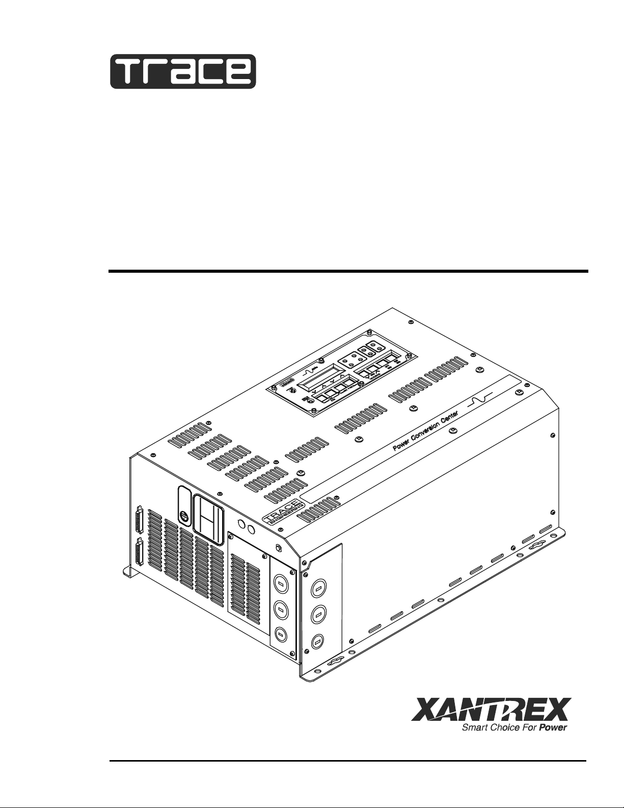
Figure 1, Identification Label .................................................................................................................. 7
Figure 2, SW Series Inverter/Charger.................................................................................................... 9
Figure 3, Control Panel........................................................................................................................... 9
Figure 4, AC Side................................................................................................................................. 12
Figure 5, Internal Components and Indicators ..................................................................................... 13
Figure 6, Aux and Gen Control Relays................................................................................................. 14
Figure 7, DC Side................................................................................................................................. 14
Figure 8, Air Flow Intake Location........................................................................................................ 18
Figure 9, AC Input/Output Power Connection......................................................................................19
Figure 10, Warning Label..................................................................................................................... 21
Figure 11, Battery to Inverter Cable Connection .................................................................................. 24
Figure 12, Neutral-To-Ground Bond Switching: No External AC Source Connected........................... 27
Figure 13, Neutral-To-Ground Bond Switching: External AC Source Connected ................................ 28
Figure 14, Neutral-To-Ground Bond Switching: Neutral Bonded To Ground....................................... 28
Figure 15, Multiple Point Ground System............................................................................................. 29
Figure 16, Single Point Ground System ............................................................................................... 29
Figure 17, Trace™ SW Series Inverter Simple Block Diagram ........................................................... 57
Figure 18, Trace™ SW Series Inverter Output Waveform................................................................... 58
Figure 19, Trace™ SW Series Efficiency Curves.................................................................................. 59
Figure 20, Inverter Capacity vs. Temperature...................................................................................... 60
Figure 21, Three-Stage Battery Charging ............................................................................................ 64
Figure 22, BTS (Battery Temperature Sensor) .................................................................................... 65
Figure 23, Two Wire Start Wiring Diagram .......................................................................................... 76
Figure 24, Three Wire Start Wiring Diagram (HONDA Type) .............................................................. 77
Figure 25, Three Wire Start Wiring Diagram (ONAN Type)................................................................. 77
Figure 26, Relay RY7 and RY8 Sequence...........................................................................................78
Figure 27, Selling Power From A DC Charging Source; Hypothetical Time Of Day Oper. History...... 85
Figure 28, Selling Power Stored In The Batteries; Hypothetical Time Of Day Operational History...... 86
Figure 29, Utility Interactive Line-Tie System With Battery Backup Flow Diagram.............................. 88
Figure 30, Overvoltage Protection for Battery ...................................................................................... 89
Figure 31, Series Configuration: 6-Volt Battery Wiring....................................................................... 107
Figure 32, Series Configuration: 12-Volt Battery Wiring..................................................................... 107
Figure 33, Parallel Configuration: 12-Volt Battery Wiring................................................................... 108
Figure 34, Series-Parallel Configuration: 6-Volt Battery Wiring.......................................................... 109
Figure 35, Series-Parallel Configuration: 12-Volt Battery Wiring........................................................ 109
Figure 36, AC Waveforms.................................................................................................................. 116
Figure 37, SW Series Dimensions: With AC Access Covers – Showing Knockout Sizes................. 120
Figure 38, Installation Diagram, 120 VAC, 1 Phase, Grid Connected, Generator Backup ................ 121
Figure 39, Installation Diagram, 240 VAC, 3 Wire, Grid Connected, Generator Backup................... 122
Figure 40, AWG Wire Size................................................................................................................. 131
2001 Xantrex Technology, Inc.
5916 - 195th Street N. E.
Arlington, WA 98223
Telephone: 360/435-8826
Fax: 360/435-2229
www.traceengineering.com
SW Series Inverter/Charger
Part No. 2031-5
Rev. C: February 2001
Page 8

TABLE OF CONTENTS
SW Series Inverter/Charger
INDEX OF TABLES
Table 1, AC Input and Output Wiring Connections .............................................................................. 19
Table 2, Minimum Recommended Battery Cable Size vs. Cable Length............................................. 22
Table 3, Battery Cable To Maximum Breaker/Fuse Size .....................................................................23
Table 4, Charging Setpoints For Common Battery Types.................................................................... 67
Table 5, Typical Wattage Of Common Appliances ............................................................................ 101
Table 6, Battery Charging: Charging Setpoints.................................................................................. 104
Table 7, Battery State of Charge Voltage........................................................................................... 105
Table 8, Battery Cable Inductance .....................................................................................................110
Table 9, Power Consumption Of Common Appliances...................................................................... 130
Table 10, AWG to Metric Wire Conversion Chart .............................................................................. 130
Table 11, Minimum Recommended Battery Cable Size vs. Cable Length......................................... 131
Table 12, Battery Cable to Maximum Breaker/Fuse Size................................................................... 131
Table 13, Recommended Minimum AC Wire Sizes (75° C)............................................................... 132
Table 14, Knockout/Hole Size To Conduit Size Required.................................................................. 132
Table 15, Safety Ground Wire Sizes.................................................................................................. 132
2001 Xantrex Technology, Inc.
5916 - 195th Street N. E.
Arlington, WA 98223
Telephone: 360/435-8826
Fax: 360/435-2229
www.traceengineering.com
Part No. 2031-5
Rev. C: February 2001
Page 9
IMPORTANT SAFETY INSTRUCTIONS
IMPORTANT SAFETY INSTRUCTIONS
SAVE THESE INSTRUCTIONS!
This manual contains im portant safety and operating instructions as prescribed by UL Standards for the
Trace™ SW Series Inverter/Chargers for use in residential and commercial applications. This manual
specifically covers products with the revision 4.01 software.
The 120 VAC/60 Hertz models of the SW Series Inverter/Chargers are ETL listed to UL Standard 1741
(Draft), Static Inverters and Charge Controllers for use in Photovoltaic Systems. The 12 and 24 VDC,
120 VAC/60 Hertz models of the SW Ser ies Inverter/Char gers ar e ETL lis ted to UL stan dard 458, Pow er
Converters/Inverters and Power Converter/Inverter Systems for Land Vehicles and Marine Craft.
The 120 VAC/60 Hertz models of the SW Series Inverter/Chargers are also ETL listed to Canadian
Standard CSA - C 22.2 No. 107.1 - M1, Commercial and Industrial Power Supplies.
The following Model Numbers of the SW Series Invert er/Chargers listed above comp ly with the following
EU directives:
• 89/336/EEC, “Council Directive of 3 May 1989 on the approximation of the laws of Member States
relating to Electromagnetic compatibility” (EMC)
• 73/23/EEC, “Council Directive of 19 February 1973 on the harmonization of the laws of Mem ber
States relating to electrical equipment for use within certain voltage limits” (LVD)
SW2612E SW4548AHC SW4548EPV SW2612A
SW2612EHC SW4548EHC SW2612AHC SW3048AHC SW4548E3PH
SW3024E
SW3048E
SW3048A SW3024EHC SW3048E SW4548E SW4548A
SW3048EHC SW3024E SW3048EPV SW3048E3PH
SW3024AHC SW3024A SW3048APV SW4548APV
SW3048E
The compliance of the above mentioned products with the Directives is confirmed through the
application of the following essential requirements:
Emissions and Immunity Safety
EN 50091-1
EN 50091-2 and
EN 60950
NOTE: To achieve compliance to EN50091-1, Conducted RF emissions, product mus t not be
connected to AC mains. Compliance is assured for off-grid applications only.
As the manufacturer we declare under our sole responsibility that the above mentioned products comply
with the above named directives.
GENERAL PRECAUTIONS
1. Before using the SW Series Inverter/Charger, read all instructions and cautionary markings on:
(a) the inverter/charger; (b) the batteries and; (c) all appropriate sections of this manual.
WARNING - To reduce risk of injury, charge only deep-cycle lead acid, lead antimony, lead calcium,
gel cell, absorbed glass mat, or NiCad/NiFe type rechargeable batteries. Other types of batteries
may burst, causing personal injury and damage.
2. Do not expose invert er/charger to rain, snow or liquids of any type. The inverter is designed f or indoor
mounting only. Protect the inverter from splashing if used in vehicle applications.
2001 Xantrex Technology, Inc.
5916 - 195th Street N. E.
Arlington, WA 98223
Telephone: 360/435-8826
Fax: 360/435-2229
www.traceengineering.com
SW Series Inverter/Charger
Part No. 2031-5
Rev. C: February 2001
Page
1
Page 10
IMPORTANT SAFETY INSTRUCTIONS
SW Series Inverter/Charger
3. Use of battery cable or custom attachm ent not recom mended or sold by Xantrex Tec hnology Inc. for
the SW Series Inverter/Charger may result in a risk of fire, electric shock, or injury to persons.
4. Do not disassem ble the inverter/charger. T ak e it to a qualif ied service c enter when servic e or repair is
required. Incorrect re-assembly may result in a risk of electric shock or fire.
5. To reduce risk of electric shock , disconnect all wiring bef ore attempting any maintenanc e or cleaning.
Turning off the inverter will not reduce this risk. Solar m odules produce power when expos ed to light.
Cover them with opaque material before servicing any connected equipment.
WARNING – RISK OF EXPLOSIVE GASSES
(a) WORKING IN VICINITY OF A LEAD ACID BATTERY IS DANGEROUS. BATTERIES
GENERATE EXPLOSIVE GASES DURING NORMAL BATTERY OPERATION. FOR THIS
REASON, IT IS OF UTMOST IMPORTANCE THAT EACH TIME BEFORE SERVICING
EQUIPMENT IN THE VICINITY OF THE BATTERY, YOU READ THIS MANUAL AND
FOLLOW THE INSTRUCTIONS EXACTLY.
(b) To reduce risk of batter y explosion, follow the instructions in this manual and those publis hed
by the battery manufacturer as well as manufactur er of any additional equipment us ed in the
vicinity of the battery. Review all cautionary markings on these products.
SPECIAL NOTICES
1. Tools required to make AC and DC wiring connections: Wire strippers; 1/2" (13MM) open-end or
socket wrench; Phillips #2 screwdriver; flat blade 1/4" (6MM) screwdriver.
2. No terminals or lugs are required for hook-up of the AC wiring. AC wiring must be copper wire and
rated for 75°C or higher. The maximum wire size for the AC terminals is #6 AWG (4.11 mm diameter).
Battery cables must be rated for 75°C or higher. Crimped and sealed copper ring ter minal lugs with a
5/16 hole should be used to connect the battery cables to the DC terminals of the inver ter/charger.
Soldered cable lugs are also acceptable.
3. Torque all AC wiring connections to 20 inch-pounds. T orque all DC cable connections to 10-15 footpounds. Avoid dropping metal tools onto the batteries. A s hort-circuit could result in a spar k, fire or
possible explosion.
4. T his inverter /c harger is designed for use with a battery supply with a nominal voltage that matches the
last two digits of the model number (e.g., 12 Volt with an SW2512).
5. For instructions on mounting, see the MOUNTING section on page 17 of this manual.
NOTE: Do not use the keyhole mounting slots for permanent ins tallations. F or battery installation
and maintenance refer to the battery manufacturer’s instructions.
6. No AC or DC disconnects are provided as an integral part of this inverter. Both AC and DC
disconnects must be pr ovided as part of the s ystem installation. Refer to the INSTALLATION section
beginning on page 15 for more information.
7. No overcurrent protection for the battery supply is provided as an integral part of this inverter.
Overcurrent protection of the battery cables must be provided as part of the system ins tallation. Refer
to the INSTALLATION section beginning on page 15 and the DC DISCONNECT AND
OVERCURRENT PROTECTION section on page 23 for more information.
8. No over current protection for the AC output wiring is provided as an integral part of this inverter.
Overcurrent protection of the AC output wiring m ust be provided as part of the system installation. Refer to
the INSTALLATION section on page 15 and the AC WIRING section on page 18 for more information.
9. The AC output neutral conductor and DC negative conductors are not connected (bonded) to the
inverter chassis. Both the input and output conductors are isolated from the enc losur e and eac h other.
System grounding, if required by sections 690-40, and 690-42 of the National Electric Code,
ANSI/NFPA 70-1996, is the responsibility of the system installer. All installations m ust comply with
local and national electrical codes and standards.
Page
2
2001 Xantrex Technology, Inc.
5916 - 195th Street N. E.
Arlington, WA 98223
Telephone: 360/435-8826
Fax: 360/435-2229
www.traceengineering.com
Part No. 2031-5
Rev. C: February 2001
Page 11

IMPORTANT SAFETY INSTRUCTIONS
10. GROUNDING INSTRUCTIONS - This inverter/battery charger should be connected to a grounded,
permanent wiring system. For m ost installations, the negative battery conductor should be bonded to
the grounding system at one (and only one point) in the system. All installations should com ply with
national and local codes and ordinances. Refer to the SYSTEM GROUNDING section on page 26 for
more information.
PERSONAL PRECAUTIONS
1. Someone should be within range of your voice or close enough to come to your aid when you work
near batteries.
2. Have plenty of fresh water and soap nearby in case battery acid contacts skin, clothing, or eyes.
3. Wear complete eye protection and clothing protection. Avoid touching eyes while working near
batteries. Wash your hands when done.
4. If battery acid contacts skin or clothing, wash immediately with soap and water. If acid enters eye,
immediately flood eye with running cool water for at least 15 minutes and get medical attention immediately.
(a) Baking soda neutralizes lead acid battery electrolyte.
(b) Vinegar neutralizes spilled NiCad and NiFe battery electrolyte.
(c) Keep a supply on hand in the area of the batteries.
5. NEVER smoke or allow a spark or flame in vicinity of a battery or generator.
6. Be extra cautious to reduce the risk of dropping a metal tool onto batteries. It could short-circuit the
batteries or other electrical parts that may result in a spark which could cause an explosion.
7. Remove personal m etal items such as rings, brac elets, necklaces , and watches when working with a
battery. A battery can produce a short-c ircuit current high enough to weld a ring or the like to metal,
causing severe burns.
8. NEVER charge a frozen battery.
9. If necessary to remove the battery, make s ure all accessories are off. Then, rem ove the grounded
terminal from the battery first.
10. If a remote or automatic generator
control system is used, disable the automatic starting circuit and/or
disconnect the generator from its starting battery while perform ing maintenanc e to prevent accidental
starting.
11. Provide ventilation to outdoors from the battery compartment. The battery enclosure should be
designed to prevent accumulation and conc entration of hydrogen gas in “pockets” at the top of the
compartment. Vent the batter y compartment from the highest point. A sloped lid c an also be used to
direct the flow to the vent opening location.
12. Clean battery terminals. Be careful to keep corrosion from coming in contact with eyes.
13. Study all the battery manufacturer’s specif ic precautions, s uch as rem oving or not rem oving cell caps
while charging and recommended rates of charge.
14. For flooded lead acid batteries, add distilled water in each cell until the battery acid reaches the level
specified by the battery manufacturer. This helps purge excessive gas fumes from the cells. Do not
overfill. For a battery without cell caps, carefully follow the manufacturer’s recharging instructions.
2001 Xantrex Technology, Inc.
5916 - 195th Street N. E.
Arlington, WA 98223
Telephone: 360/435-8826
Fax: 360/435-2229
www.traceengineering.com
SW Series Inverter/Charger
Part No. 2031-5
Rev. C: February 2001
Page
3
Page 12

IMPORTANT SAFETY INSTRUCTIONS
SW Series Inverter/Charger
Page
4
2001 Xantrex Technology, Inc.
5916 - 195th Street N. E.
Arlington, WA 98223
Telephone: 360/435-8826
Fax: 360/435-2229
www.traceengineering.com
Part No. 2031-5
Rev. C: February 2001
Page 13
INTRODUCTION
INTRODUCTION
Congratulations! You are the proud owner of the finest inverter on the market today - and one very
complex piece of equipment. T he Trace™ Sine wave (SW Series) Inverter/Charger has many features
and capabilities previously either non-existent, or found only in separate products.
With proper installation, the inverter will operate satisf actor ily for many applications str aight out of the box ,
using the factory default settings. To fully utilize the inverter's generator interactive, or utility interactive
capabilities, it is necessary to understand the way the inverter operates and then tailor its operation via the
Control Panel and the USER and SETUP menu systems. This manual will provide the necessary
information. However, it is recom mended that you consult with your authorized dealer to ensure correct
installation and maximum utilization of the numerous featur es of this produc t. If you do not understand any
aspect of installation, contact your authorized Xantrex dealer/installer for assistance.
If you intend to operate the inverter in a utility interactive mode, in which power will be sold to the utility,
you must contact the local utility office and get their approval. T he utility may require additional inf or mation
that may not be included in this manual. Please contact your authorized Xantrex dealer/installer for
assistance.
As a minimum , you should read the sections of the manual that relate to your type of installation. The
MENU SYSTEM section, beginning on page 33, explains how to make changes to the inverter’s
user/setup menus. T he OPERATION section, beginning on page 57, explains how the inverter works in
each of its different operating modes. Focus on the operating modes that relate best to your type of
installation and make the appropriate selections and adjustm ents. Installation diagrams are provided for
many of the various applications. This m enu system provides contro l of the inverter, allows features to be
enabled, and allows setting of operating parameters.
This is a long manual and much of it is fairly technical. Throughout this m anual terms may be used that
are unfamiliar, see the INVERTER/CHARGER TERMINOLOGY glossary on page 115 for clarification. If
you are an insomniac, properly used, this manual is guaranteed to provide several good nights of sleep.
Note: This manual is specific to the REVISION 4.01 software. Some featur es disc ussed may not
be included in previous software revisions provided in inverters manufactured before March
1996.
You can verify that the inverter is using REVISION 4.01 software by checking under the TRACE
ENGINEERING (3) m enu heading. The second menu item should read REVISION 4.01. If your inverter
includes a previous software version, please contact your authorized Xantrex dealer r egarding upgrade
options.
2001 Xantrex Technology, Inc.
5916 - 195th Street N. E.
Arlington, WA 98223
Telephone: 360/435-8826
Fax: 360/435-2229
www.traceengineering.com
SW Series Inverter/Charger
Part No. 2031-5
Rev. C: February 2001
Page
5
Page 14

INTRODUCTION
SW Series Inverter/Charger
Page
6
2001 Xantrex Technology, Inc.
5916 - 195th Street N. E.
Arlington, WA 98223
Telephone: 360/435-8826
Fax: 360/435-2229
www.traceengineering.com
Part No. 2031-5
Rev. C: February 2001
Page 15
UNIT IDENTIFICATION
UNIT IDENTIFICATION
This section describes the marking and location of the model and serial numbers for SW Series
Inverter/Chargers. Use this section to determine the type and model of your inverter/charger. The unit
identification label on the left side panel of the inverter/charger will show the serial number, model number,
listings, ratings, and date of manufacture.
Model Number
DC Input Voltage
Operating Range
AC Input/Output
Phase,
Quarter and Year of
Manufacture
Waveform,
Frequency and
Voltage
Product Code and Serial
Number
Figure 1, Identification Label
MODEL NUMBER
The Model Number of your inverter determines the different features your unit m ay have. Consider the
following unit with a SW4024 model number:
SW 40 24 *
Model Power Nominal DC
Voltage
Model: The first letter(s) (SW) indicate the model, in this case the SW Series.
Power: The first and second positions in the model num ber indicate the continuous AC power output in
hundreds of VA (Volt-Amps). Power levels available s tart at 2500 up to 5500 Volt-Amps with different DC
voltages. In the example above, 40 would stand for a 4000 VA (4 kVA), continuous-output inverter.
Input/Output DC Voltage: The number (24) following the power rating indicates an inverter/charger that
is designed to convert 24 VDC input to an AC voltage
output, and charge 24 VDC batteries when powered
by the same AC voltage. Available DC voltages are 12, 24 and 48 volt models.
AC Voltage/Options
Input/Output AC Voltage/Options: The letter following the power rating indicates what AC voltage and
frequency or particular option this inverter/charger is specifically designed to provide. No letter after the
DC voltage number indicates an AC voltage of 120 VAC/60 Hz and requires the s ame AC voltage and
frequency (120 VAC/60 Hz) to charge the inverter batteries. Available voltages range from 105 to 240
VAC at 50 or 60 Hz.
See the SPECIFICATIONS AND FEATURES section, on page 118, for the different models available.
2001 Xantrex Technology, Inc.
5916 - 195th Street N. E.
Arlington, WA 98223
Telephone: 360/435-8826
Fax: 360/435-2229
www.traceengineering.com
SW Series Inverter/Charger
Part No. 2031-5
Rev. C: February 2001
Page
7
Page 16

UNIT IDENTIFICATION
SW Series Inverter/Charger
Page
8
2001 Xantrex Technology, Inc.
5916 - 195th Street N. E.
Arlington, WA 98223
Telephone: 360/435-8826
Fax: 360/435-2229
www.traceengineering.com
Part No. 2031-5
Rev. C: February 2001
Page 17
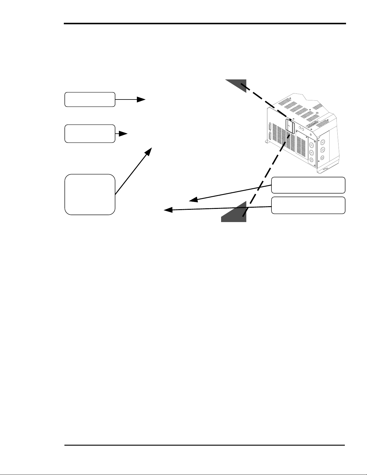
CONTROLS, INDICATORS AND COMPONENTS
CONTROLS, INDICATORS AND COMPONENTS
The SW Series Inver ter/Chargers have an integral, full f unction Control Panel with LED status indicators.
The following components are als o included: inverter/charger circ uit breaker; battery tem perature sensor
(BTS) port, remote port, and a stacking port.
Stacking Interface
Remote Interface
Control Panel
AC Side
DC Side
BTS Sensor Input
Circuit Breaker
Figure 2, SW Series Inverter/Charger
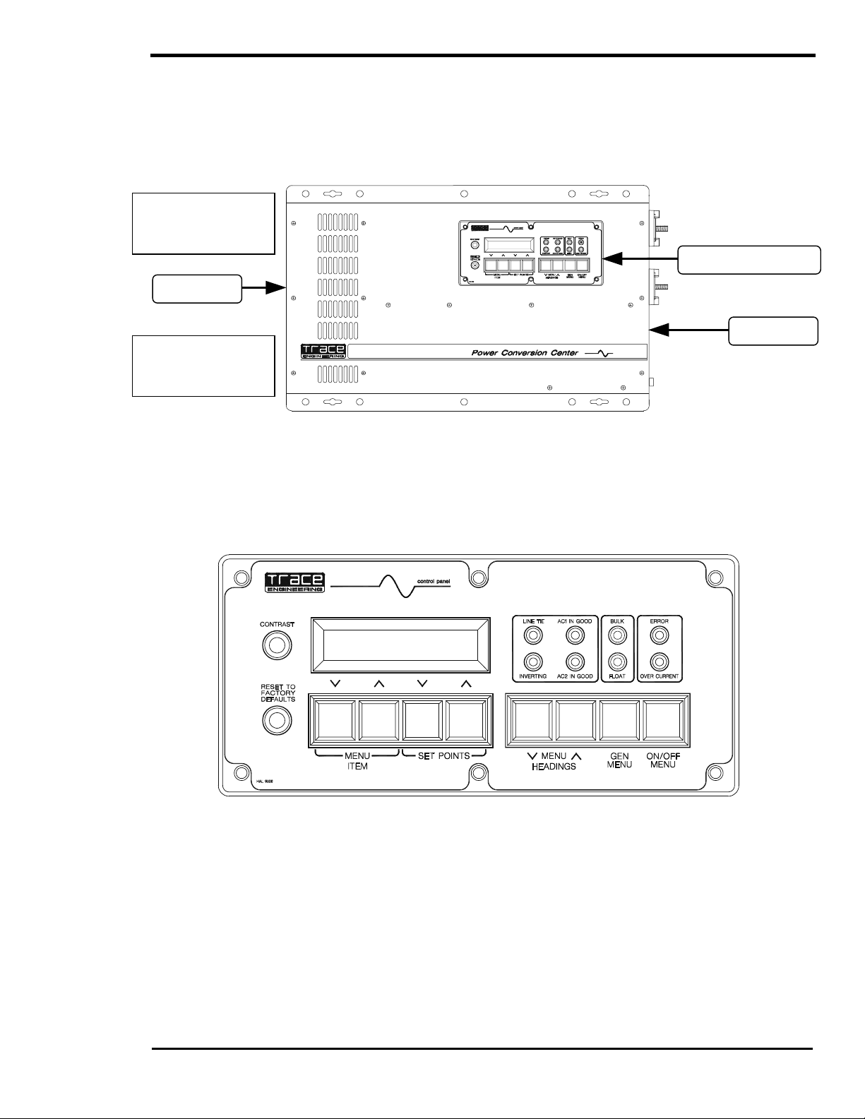
CONTROL PANEL
The Control Panel, on the front of the SW Series Inverter/Charger, provides the controls and displays
needed to adjust, control and monitor the oper ation of the unit. T he contr ol panel is operational whenever
DC power is applied to the inverter DC input terminals.
Figure 3, Control Panel
Eight pushbuttons are used to select the various menus, menu items and oper ating setpoint values f or the
unit, including the ability to turn the inverter on and off. A Liquid Crystal Display (LCD) presents the various
system settings and data as selected by the operation of the MENU BUTTONS on the control panel. Eight
LED indicators are provided to show the operating condition of the inverter, battery charger, AC inputs and
self-protection systems.
DISPLAY
The Liquid Crystal Display (LCD) displays data as selected by the menu buttons. Refer to the USER
MENU, beginning on page 36, and the SETUP MENU, beginning on page 44, for specific information on
the Menu Items, functions and display information.
2001 Xantrex Technology, Inc.
5916 - 195th Street N. E.
Arlington, WA 98223
Telephone: 360/435-8826
Fax: 360/435-2229
www.traceengineering.com
SW Series Inverter/Charger
Part No. 2031-5
Rev. C: February 2001
Page
9
Page 18

CONTROLS, INDICATORS AND COMPONENTS
SW Series Inverter/Charger
CONTRAST CONTROL
The CONTRAST adjustm ent enables you to adjust the contrast of the LCD display screen to accomm odate
changing lighting conditions. Less contrast is usually preferable in brighter lighting conditions.
RESET TO FACTORY DEFAULTS BUTTON
The RESET TO FACTORY DEFAULTS button returns all of the inver ter settings (exc ept for the TIME OF
DAY settings) to the factory default values. The def ault values will be re-entered only when this button is
pushed from a spec ific m enu item in the USER MENU. You must first select the TRACE ENGINEERING
(3) menu heading and then go to the first menu item, which will display “PRESS RESET NOW FOR
DEFAULTS”. Once this reset button is pressed from this menu item, you must reprogram all settings
required by your installation into the inverter.
Removing DC power from the inverter will also return the inverter to the factory default values
(including the TIME OF DAY settings). You must then reprogram the inverter with the required settings
for proper operation of your system. Recording your settings on the USER SETT INGS W ORKSHEET, in
the TECHNICAL INFORMATION section of this manual, will make the reprogramming of the inverter
much easier.
The reset button is also used to re-synchronize the remote control (SW RC) display if the charac ters bec om e
jumbled. Pressing the reset button anywhere in the menu s ystem ( except the PRESS RESET NOW FOR
DEFAULTS menu item) will re-synchronize the display, but the default values will not be reset.
MENU BUTTONS
ON/OFF MENU BUTTON (Red)
Pressing the red ON/OFF MENU button at any time will take you directly to the SET INVERTER menu
item of the INVERTER MODE (1) menu heading. There are four options available from this m enu item.
The first letter of the selec ted item will be underlined. Pressing the red ON/OFF MENU button will move
the cursor one position to the right, selecting the next item. You can also use the SET POINT S buttons to
move either right or left.
GEN MENU BUTTON (Green)
Pressing the green GEN MENU button at any time will display the SET GENERATOR menu item of the
GENERATOR MODE (2) menu heading. There are four options available from this menu. The f irst letter
of the selected item will be underlined. Pres sing the green GEN MENU button will move the cursor one
position to the right, selecting the next item. You can also us e the SET POINTS buttons to move either
right or left.
MENU ACCESS/ADJUSTMENT BUTTONS (Black)
The MENU HEADING buttons are used to move either up or down through the selection of menu
headings. Once a menu heading is selected, the MENU ITEM buttons are used to move up or down
through the list of related menu items. The SET POINTS buttons change the value of a parameter or
select a mode, for the selected menu item.
LED STATUS INDICATORS
The Control Panel features eight colored LED indicators that identify the various operating conditions of
the inverter. Unless otherwise indicated, the LED’s will be "solid" in appearance, when illuminated.
LINE TIE (Yellow)
Selecting SELL from the GRID USAGE menu item under the INVERTER SET UP (9) menu heading will
enable sell mode. This should only be done with utility connected systems and after you have received the
approval of the local utility. This mode allows excess power to be sent into the utility grid.
INVERTING (Yellow)
The inverter is operational and AC output is available. If this LED is blinking, the inverter is in the search
mode and is looking for an AC load greater than the SET SEARCH WATTS setting.
Page
10
2001 Xantrex Technology, Inc.
5916 - 195th Street N. E.
Arlington, WA 98223
Telephone: 360/435-8826
Fax: 360/435-2229
www.traceengineering.com
Part No. 2031-5
Rev. C: February 2001
Page 19

CONTROLS, INDICATORS AND COMPONENTS
AC1 IN GOOD (Green)
Indicates that AC power is present at the AC HOT IN 1 and NEUTRAL IN 1 input terminals. T his input is
intended for utility power. When an AC sourc e is connected to the input term inals, it will s tart to blink slowly
(once a second) to show the AC voltage has been detected. After the inverter has connected to the AC
source, the LED will be solid. If the LED starts to blink during operation, utility power has been dropped.
AC2 IN GOOD (Green)
Indicates that AC power is present at the AC HOT IN 2 and NEUTRAL IN 2 input terminals. T his input is
intended for generator power. When an AC source is connected to the input ter minals, it will start to blink
slowly (once a second) to show the AC voltage has been detected. After the inverter has connected to the
AC source, the LED will be solid. If the LED starts to blink during operation, generator power may have been
dropped.
This LED will also blink slowly (once a second) when the automatic generator control system is enabled.
When the generator has star ted, it will continue to blink slowly until the generator has been connected. If the
generator does not successfully start, the AC 2 IN GOOD LED w ill stop blinking and the red ERROR LED will
turn on. The ERROR CAUSES (5) menu heading will indicate a GENERATOR SYNC ERROR condition.
BULK (Yellow)
This indicator will be on to indicate the inverter is in the Bulk or Absor ption char ge s tage. This indicator will
go off and the FLOAT indicator will illuminate when the battery voltage has been held near the SET BULK
VOLTS DC setting for the time period determined by the SET ABSORPTION TIME setting from the
BATTERY CHARGING (10) menu heading.
If the EQ mode is selec ted from the SET GENERATOR menu item under the GENERATOR MODE (2)
menu heading, the BULK LED will slowly blink while the charger completes the equalization process.
FLOAT (Green)
This indicator will be on when the battery voltage has reached the Float Stage of the charging proc ess. It
will now regulate the charging process to the SET FLOAT VOLTS DC setting from the BATTERY
CHARGING (10) menu heading. The SET FLOAT VOLTS DC setting provides a maintenance c harge to
the battery until another Bulk Charge Cycle is initiated or the AC sourc e is disconnected. If a generator is
manually controlled and powering the battery charger, the FLOAT indicator will com e on to indicate that
the generator should be turned off, since the battery is now fully charged.
This indicator is also used to indicate the r egulation setpoint when the inverter is operating as an Utility
Interactive Inverter (SELL mode). The indicator will blink s lowly to indicate the battery is regulated to the
SET BATTERY SELL VOLTS DC setting from the BATTERY SELLING (17) menu heading, and the
indicator will be “solid” to indicate the battery is regulated to the SET FLOAT VOLTS DC setting from the
BATTERY CHARGING (10) menu heading.
ERROR (Red)
Indicates that an operating error has occur red (refer to the ERRO R CAUSES (5) menu heading f or a list
of possible causes). T o reset the inverter, pres s the red ON/OFF MENU button and then select OFF and
then ON with the SET POINTS buttons or by pressing the red button several times.
This indicator will blink slowly to indicate that the AC source f requency is not well-adjusted (3 to 7 hertz
from nominal). You can use the LED blink to help adjust the AC source frequenc y. Once the frequency is
within 3 hertz of your nominal frequency, the LED will turn off.
OVERCURRENT (Red)
The load requirement has ex ceeded the inverter’s maximum output AC am ps. A sustained overcurrent
condition will require a manual reset by pressing the red ON/OFF MENU button and then selecting OFF
and then ON with the SET POINTS buttons or by pressing the red button several times. Momentary
flashing of the red OVERCURRENT indicator means that the inverter has reac hed it max imum output AC
amps and has automatically reset itself. This may occur during motor startups and is acceptable.
2001 Xantrex Technology, Inc.
5916 - 195th Street N. E.
Arlington, WA 98223
Telephone: 360/435-8826
Fax: 360/435-2229
www.traceengineering.com
SW Series Inverter/Charger
Part No. 2031-5
Rev. C: February 2001
Page
11
Page 20
CONTROLS, INDICATORS AND COMPONENTS
SW Series Inverter/Charger
AC SIDE
Figure 4 shows the components located on the AC side of the inverter. T he rem ovable AC Acc ess Panels
cover and protect the Internal Components and Indicators, such as the AC Terminal Block, BTS
Connection, LED status indicators (for the AC1 and Gen Control relays) and the Aux and Gen Control
relay terminals. Refer to the INSTALLATION section beginning on page 15, for all wiring connections.
Inverter/
Identification
Label
Remote
Port
Charger
Circuit Breaker
Knockouts
(Also On Side}
Stacking
Port
Three
Removable
Access Panel
(One Panel on
Side)
Figure 4, AC Side
REMOTE PORT
The SW Series Inverter/Charger can be controlled remotely from the unit by plugging in a Sine wave
Remote Control (SWRC) or Sine wave Communications Adapter (SWCA).
The SWRC remote control is a full function, programmable remote control with backlit LCD which
duplicates the functions of the integral Control Panel.
The SWCA serial communications interf ace adapter allows for rem ote setup, adjustment, m onitoring and
troubleshooting of SW Series Inverter/Chargers from a personal computer and allows modem access
monitoring over long distances.
See the APPENDIX, OPTIONS section, starting on page 128, for a com plete description of the SW RC
Remote Control and SWCA Serial Communications Adapter.
STACKING PORT
The stacking port allows multiple SW Series Inverter/Chargers to be used in the same system. The
inverters can be used in a “SERIES” configuration to operate 240 Vac loads and to connect to
120/240 Vac power systems. A series stacking interface cable (SWI) is required to connect the series
stacking ports of the inverters. This port is als o used to c onnect two units in a “PARALLEL” configur ation.
The parallel stacking inter face cable (SWI/PAR) allows two inverters to be connected to provide twice the
continuous and surge capability at the same AC voltage. See the U SING MULTIPLE INVER TERS section
on page 95 for more information.
INVERTER/CHARGER CIRCUIT BREAKER
This circuit break er protects the unit’s internal wiring while the unit is inverting or charging. It is not used
for the pass-through current. This is not a branch-circuit rated breaker, separate output breakers are
required. Press the breaker to reset (to reset on 48-volt units, move the breaker handle to the ON
position).
Page
12
2001 Xantrex Technology, Inc.
5916 - 195th Street N. E.
Arlington, WA 98223
Telephone: 360/435-8826
Fax: 360/435-2229
www.traceengineering.com
Part No. 2031-5
Rev. C: February 2001
Page 21
CONTROLS, INDICATORS AND COMPONENTS
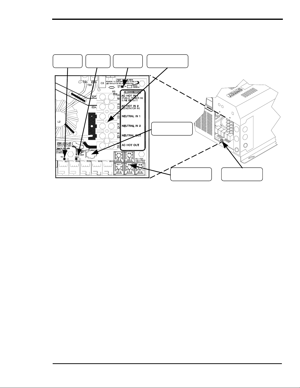
INTERNAL COMPONENTS AND INDICATORS
Additional components and indicators ar e located behind three removable AC Access Panels located on
the AC Side of the unit. They include the AC Terminal Block , BTS Connector, three LED indicators and
the Aux and Gen Control Relay Connectors.
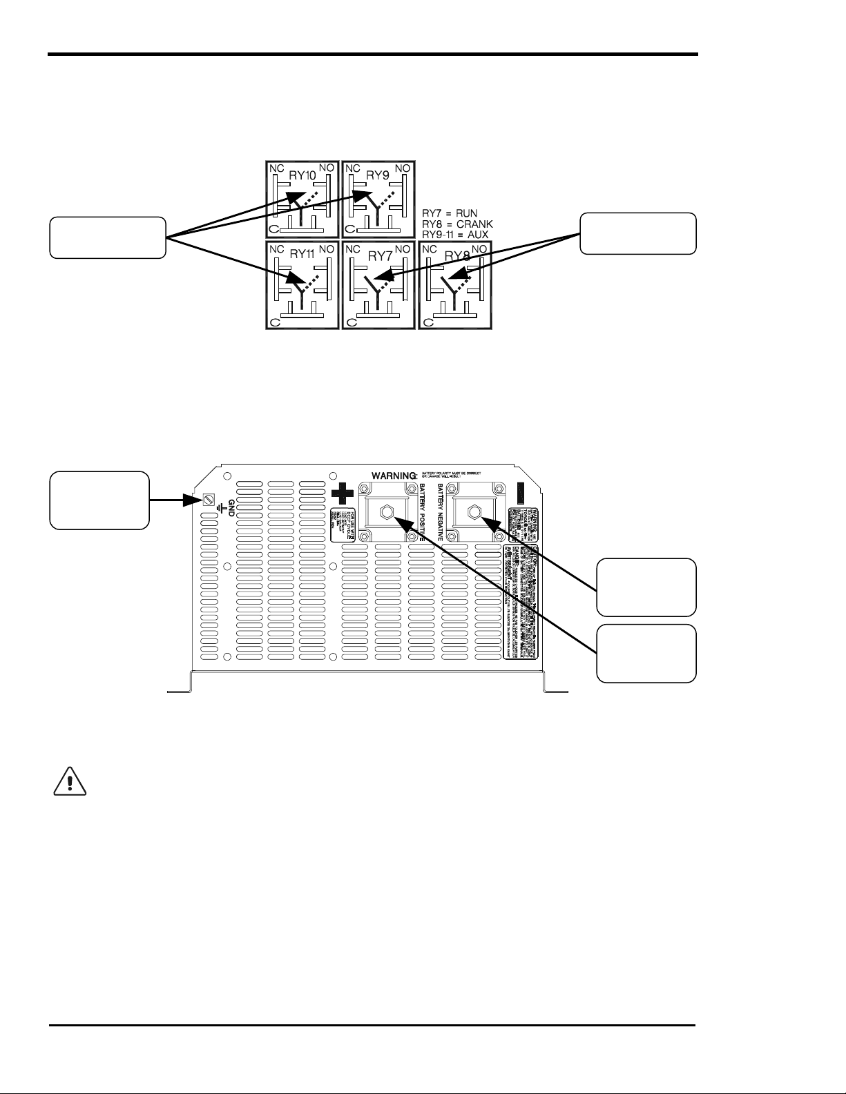
RY7 (Yellow)
LED
RY8 (Green)
LED
AC1 Relay
(Red) LED
Figure 5, Internal Components and Indicators
LED INDICATORS
AC
Terminal Block
BTS
Connector
Aux and Gen Control
Relay Connectors
AC
Safety Ground
Three LED indicators allow visual indication of operation of the RY7, RY8 and AC1 relays.
RY7 (Yellow) LED
Allows visual indication of relay RY7 operation. During the automatic generator control sequence, the
LED will be on to show that RY7 is closed (engaged) from the N.O. to the COM contacts, and will be
off when RY7 is opened (disengaged).
RY8 (Green) LED
Allows visual indication of relay RY8 operation. Dur ing the automatic generator control sequenc e, the
LED will be on to show that RY8 is closed (engaged) from the N.O. to the COM contacts, and will be
off when RY8 is opened (disengaged).
AC1 RELAY (Red) LED
Allows visual indication of AC1 relay operation. The LED will be on when the AC1 relay is closed
(engaged). This LED along with the test-jumper adjacent to the LED is used by utilities to perform
voltage and frequency tests to qualify the SW Series Inverter/Charger for line-tie applications.
BTS PORT
The battery temperature sensor (BTS) can be connected (plugged in) at the RJ-11 four-conductor
connector, located on the AC Circuit Board. T he BTS provides information that enables the three-stage
standby battery charger to “fine tune” the battery charge voltages for better charging per form anc e, greater
efficiency and longer battery life.
AC TERMINAL BLOCK
A six position terminal block is provided to m ak e the AC connec tions. T he term inal block is located on the
AC Circuit Board. The terminal block is used to hardwire all AC input and output connections.
2001 Xantrex Technology, Inc.
5916 - 195th Street N. E.
Arlington, WA 98223
Telephone: 360/435-8826
Fax: 360/435-2229
www.traceengineering.com
SW Series Inverter/Charger
Part No. 2031-5
Rev. C: February 2001
Page
13
Page 22
CONTROLS, INDICATORS AND COMPONENTS
SW Series Inverter/Charger
AC SAFETY GROUND
The AC Safety Ground is used to connect the inverter chassis to the AC Grounding System.
AUXILIARY AND GENERATOR CONTROL RELAY CONNECTORS
Auxiliary Control
Relay Connectors
Generator Control
Relay Connectors
Figure 6, Auxiliary and Generator Control Relay Connectors
DC SIDE
Figure 5 shows the components located on the DC side of the inverter. Refer to the INSTALLATION
section for the battery wiring connections to the Battery Terminals and the DC Ground.
DC
(Equipment)
Ground
Battery
Terminal
(-)
Battery
Terminal
(+)
Figure 7, DC Side
BATTERY TERMINALS
Caution: Before connecting the battery cables to the inverter, ver ify the correct battery voltage
and cable polarity using a voltmeter. The inverter is not reverse polarity protected. If the
positive terminal of the battery is co nnected to the negative terminal of the inverter and
vice versa, severe damage will result. If necessary, color- code the cables with colored tape or
heat shrink tubing: RED for positive (+); BLACK for negative (-) to avoid polarity problems.
DC (EQUIPMENT) GROUND
This connection is used to connect the exposed chassis of the inverter to the DC grounding system. The
terminal accepts wires from #14 AWG to #2 AWG.
Page
14
2001 Xantrex Technology, Inc.
5916 - 195th Street N. E.
Arlington, WA 98223
Telephone: 360/435-8826
Fax: 360/435-2229
www.traceengineering.com
Part No. 2031-5
Rev. C: February 2001
Page 23

INSTALLATION
INSTALLATION
This section is very important, since it tells you how to properly install your SW Series Inverter/Charger.
It becomes very frustrating when your inverter system does not perform properly, simply because car e
was not taken during installation. Please read this entir e section carefully. You will save time and avoid
common mistakes.
This section also describes the requirements and recommendations for installing the SW Series
Inverter/Charger. In the U.S., the National Electrical Code (NEC) def ines the standards for both the AC
and DC wiring in residential, commerc ial and RV applications. It will list the requirement for wire sizes,
overcurrent protection and installation m ethods and r equirem ents. T here ar e still m any other variables not
covered by the NEC. Most are determined by the level of automatic operation, the am ount of external AC
and DC power to be controlled and the loads to be operated.
The NEC standards and regulations are described here in general for your convenience, and are not
represented as comprehensive or complete. For comprehensive and complete official standards and
regulations, write the address listed below:
NFPA - National Fire Protection Association
National Electrical Code Handbook
1 Batterymarch Park,
PO Box 9101
Quincy, MA 02269-9101
617-770-3000.
Before beginning the installation of the SW Series Inverter/Charger , read all instructions. Disconnect all
sources of AC and DC power to prevent accidental shoc k. Disable and sec ure all AC and DC disconnec t
devices and automatic generator starting devices.
All installations should meet all local codes and standards and be performed by qualified
personnel such as a licensed electrician. Although the DC electrical system may be “low voltage”,
significant hazards may be present, particularly from s hort circuits of the battery system. Inver ter systems
by their nature involve power from multiple sour ces (inverter, gener ator, utility, batteries, solar arr ays etc.)
that add hazards and complexity that can be very challenging.
After you have finished installing your unit, continue with the FUNCTIONAL TEST section on page 31.
This Functional Tes t should be completed prior to configuring your unit’s Menu System for your specific
operation.
2001 Xantrex Technology, Inc.
5916 - 195th Street N. E.
Arlington, WA 98223
Telephone: 360/435-8826
Fax: 360/435-2229
www.traceengineering.com
SW Series Inverter/Charger
Part No. 2031-5
Rev. C: February 2001
Page
15
Page 24

INSTALLATION
SW Series Inverter/Charger
QUICK INSTALL
This section provides ins tallers, licensed electrical contractors, and k nowledgeable laymen the essential
steps to quickly install the Trace™ SW Series Inverter/Charger. If you haven’t had experience with the SW
Series Inverter/Charger, you are urged to skip this s ection and read the entire INSTALLATION section
before installing the inverter/charger.
MOUNTING
Mount the unit securely in a clean, dry, properly ventilated enclosure. Do not mount the unit in the sam e
enclosure as vented or maintenance-free type vented batteries. Bolt the unit securely. Allow adequate
clearance to allow access to the indicators or controls.
DC CABLING
1. Connect an appropriate sized cable from the positive batter term inal (or batter y bank) to the inverter’s
positive (red) terminal. See T able 12 in the Appendix to determ ine the proper size c able and length of
run needed to use with your inverter model and for your specific application. The National Electric
Code (NEC) requires the use of a DC fuse or disconnect with this cable. See Table 12 in the Appendix
to determine the correct fuse or breaker to use.
2. Connect an appropriate sized cable from the negative battery terminal to the negative (black ) inverter
terminal. Torque all term inals to 10-15 foot-pounds. NOT E: A 'snap' caused by charging the internal
capacitors may occur when first connecting the cable. This can be avoided by first removing the DC
fuse or opening the disconnect in the positive battery cable.
3. Connect a cable from the inverter’s DC Chassis Ground to the system ground.
AC IN CABLING
1. See Table 13 in the Appendix to determine the appropriate AC wire size.
2. Remove the knock out from the inverter chas sis and install a strain relief or conduit in which to route
the AC cabling in and out.
3. Connect the black wire from the hot side of the AC power to the terminal labeled AC HOT IN 1 (AC
HOT IN 2 if a generator is the AC source) on the inverter.
4. Connect the white wire from the neutral side of the AC power source to the terminal labeled
NEUTRAL IN 1 (NEUTRAL IN 2 if a generator is the AC source) on the inverter.
5. Connect the green wire from the ground of the AC power source to the AC Ground Terminal of the
inverter/charger.
AC OUT CABLING
1. Connect the black wire between the terminal m arked AC HOT OUT to the hot bus of your AC load
center or AC sub-panel.
2. Connect the white wire from the term inal marked NEUTRAL OUT to the neutral bus of your AC load
center or sub-panel.
3. Connect the AC Ground Terminal of the inverter to the safety ground bus of the AC load center or
sub-panel.
WRAP UP
1. Secure all wiring with wire ties or other non-conductive fasteners to pr event chafing or damage. Use
strain-reliefs, grommets, or conduits to prevent dam age to the wiring where it passes through any
apertures. Tighten all connections to the correct torque (AC Connections at 20 inch-pounds; DC
Connections at 10-15 foot-pounds).
2. Make a final check of all wiring, then reconnect to the AC power source.
3. Turn the inverter ON and check inverter operation (See the FUNCTIONAL TEST section on page 31).
Page
16
2001 Xantrex Technology, Inc.
5916 - 195th Street N. E.
Arlington, WA 98223
Telephone: 360/435-8826
Fax: 360/435-2229
www.traceengineering.com
Part No. 2031-5
Rev. C: February 2001
Page 25
INSTALLATION
COMPLETE INSTALL
UNPACKING
Before beginning, unpack the inverter/charger; record the
serial number on the inside cover of this booklet and on the
warranty card. Right now, please do the following:
• Verify that you have everything listed on the Packaging
Materials sheet. If any items are missing, please call
Customer Service at (360) 435-8826.
• Save your “proof-of-purchase”, You will need the “proof-of-
purchase” to obtain warranty service.
• Keep the original carton and packing materials. If you
need to return your inverter for service, you should ship it
in the original carton. It is also the best way to keep the
inverter safe if it needs to be moved.
LOCATION
Inverters are sophisticated electronic devices and should be treated ac cordingly. Treat the inverter as you
would any fine piece of electronic equipment. W hen selec ting the location for the inverter , don't think of it
in the same terms as the other interf acing equipm ent, e.g. batter ies, diesel generators, motor generators,
washing machines etc. It is a highly com plex micropr ocessor c ontrolled device. There ar e nearly 500,000
silicon junctions in its output devices and integrated circuits. The crystal oscillator runs at 4 megahertz.
The drive circuitry timing is acc urate to a thousandth of a second. Genetically speaking, it is a cous in to
stereo equipment, television sets or computer s. T he us e of c onf ormal-coated circuit boards, plated c opper
bus bars, powder coated metal components , and stainless steel fasteners impr oves tolerance to hostile
environments. However, in a corrosive or condensing environment (one in which humidity and/or
temperature change cause water to f orm on com ponents) all the ingredients for electrolysis are pres ent water, electricity and metals. In a corrosive or condensing environment, the life expectancy of the
inverter is indeterminate and the warranty is voided.
Caution: Install the inverter in a dry, protected loc ation away from sources of high temperature
and moisture. Exposure to saltwater is particularly destructive and potentially hazardous.
Locate the inverter as close to the batteries as pos sible in order to keep the battery cable length short.
Do not locate the inverter direc tly above the batteries or in the same compartment as vented batteries.
Batteries generate hydrogen sulfide gas, which is very corrosive to electronic equipm ent and everything
else. They also generate hydrogen and oxygen. If these gases accumulate, an arc caused by the
connecting of battery cables or the switching of a relay could ignite the mix ture. Mounting the inverter in a
ventilated enclosure with sealed batteries is acceptable.
Ensure the inverter is located in an area that prevents insects and rodents from entering the inverter , as
the inverter can provide a warm habitat in a cold environment. This m a y involve installing the inverter in an
enclosure and include mesh screens or nets over any openings to ensure the unit is kept well ventilated.
This inverter can create RFI (Radio Frequency Interference). Keep this in mind when determining the
placement of the inverter. You should locate the inverter as far away as possible from any electronic
devices that may be susceptible to RFI.
MOUNTING
UL Standard 1741 (draft) requires that the inverter be m ounted on a vertical surfac e (on a wall) and that
the keyhole slots not be used as the only method of mounting. The purpose of the wall mounting
requirement is to orient the inverter so that its bottom c over, which has no holes, will not allow burning
material to be ejected in case of an internal fire.
2001 Xantrex Technology, Inc.
5916 - 195th Street N. E.
Arlington, WA 98223
Telephone: 360/435-8826
Fax: 360/435-2229
www.traceengineering.com
SW Series Inverter/Charger
Part No. 2031-5
Rev. C: February 2001
Page
17
Page 26
INSTALLATION
SW Series Inverter/Charger
Use 1/4" minimum diameter bolts for mounting. The m ounting must be capable of supporting twice the
weight of the inverter in order to com ply with UL 1741. If this unit is used in a mobile applic ation (i.e. RV,
Boat) secure the inverter to a shelf or deck to prevent m ovem ent. Place flexible washer s on the m ounting
screws or bolts between the shelf or deck and the inverter chassis to reduce vibration.
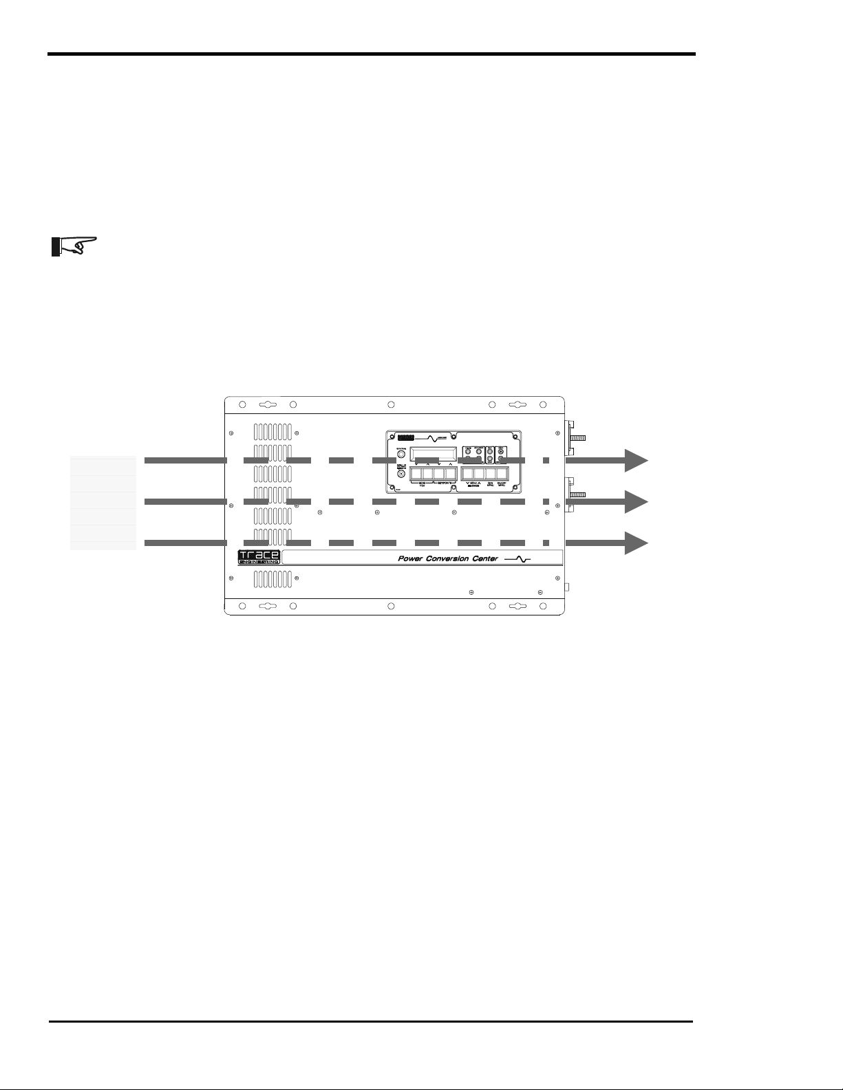
VENTILATION
Installation of the inverter in a properly ventilated enclosure is neces sary for eff icient operation of the unit.
The inverter’s thermal shutdown point will be reached sooner than normal in a poorly ventilated
environment and will result in a lower peak power output, reduced surge capability, and potentially shorter
inverter life.
Note: Do not operate the inverter in a closed-in area or restrict ventilation in any way.
Testing has shown that the volume of the enclosure is not as important as the overall ventilation. A
minimum airspace clearance of 1½ inches around the top and bottom and 3 inches of c learanc e at the lef t
and right sides of the inverter will provide adequate ventilation. Because the top and bottom of the SW
Series chassis is not vented, clearanc e between the enclosure and the top of the inverter is not critical. A
fresh air intake port s hould be provided directly to the left side and an exhaust port on the right side will
allow cool outside air to flow through the inverter and back out of the enclosure.
Top
Left
(AC Side)
Right
(DC Side)
AIR
FLOW
Bottom
Figure 8, Air Flow Intake Location
AC WIRING
This section describes AC wiring requirements and recommendations; including AC connections; wire
sizing; overcurrent devices; GFCIs; external r elays; hookup procedure; and neutral-to-ground switching.
Your local electrical code and the National Electrical Code (NEC) def ine the standards for AC ins tallation
wiring, but there are still many installation variables to be considered. Consult the local code and the NEC
for the proper wire sizes, connectors and conduit. All installations should meet all local codes and
standards and be performed by qualifie d personnel such as a licensed electrician.
AC INPUT AND OUTPUT CONNECTIONS
A six position terminal block is provided to m ak e the AC connec tions. T he term inal block is located on the
left-hand side of the inverter, enclosed under a cover plate (See INTERNAL COMPONENTS AND
INDICATORS on page 13 for location.). The term inal block can accept up to # 6 AWG str anded wire and
is used to hardwire all AC connections. For 120 VAC inverters, we recom mend 6 AWG (THHN) wire for
full utilization of the inverter’s 60 amp AC pass through capability. The code requires that disconnect
switches be provided in the AC input and output wiring circuits. AC circuit breaker s in an AC load center
can be used to meet this requirem ent. The wiring both in and out of the inverter mus t also be protected
from short circuits and overloads by a fuse or circuit breaker. Typically, a 60 amp circuit breaker will
protect #6 AWG wiring. Consult your local code for more information and for other wire sizes.
Page
18
2001 Xantrex Technology, Inc.
5916 - 195th Street N. E.
Arlington, WA 98223
Telephone: 360/435-8826
Fax: 360/435-2229
www.traceengineering.com
Part No. 2031-5
Rev. C: February 2001
Page 27
INSTALLATION
Note: The three neutral terminals are common to each other and can be used in any combination or
order. In a residential application, it is often easier to only connect one AC neutral wire to the inverter and
make the other neutral connections at a central point such as in the AC load center, etc. In mobile
installations, the AC system must have the neutral physically isolated from the gr ound throughout the load
distribution powered by the inverter. The SW Series Inverter/Charger does not include neutral to ground
switching for the AC electrical system. This must be done externally from the inverter. See the NEUTRAL-
TO-GROUND BOND SWITCHING (RV AND MARINE APPLICATIONS) section on page 27 for more
information.
AC Terminal Block
(TB1)
1b
1a
AC IN 1
2b
AC IN 2
From
Generator Power
2a
3a
4a
3b
4b
From
Utility Power
5b
5a
AC OUT
To
6a
6b
AC Loads
Figure 9, AC Input/Output Power Connection
Before making any AC connections, make sure that the inverter is disconnected from the battery (or
battery bank). Feed the wires through conduit fittings located on the left s ide or left bottom side of the
inverter. (Note: Conduit fittings must be purchased separately and are required by code to comply with
residential and commercial installations).
The AC wiring both in and out of the inverter must also be protected from short circuits and overloads by a fuse
or circuit breaker. Consult the NEC or your local code for more information and for other wire sizes. Table 13 on
page 132 gives suggestions for wire sizing. Follow the wiring guide on the circuit board inside the cover plate
(see Figure 9, above). Connect the AC wiring as follows (from front to back when wall mounted):
Table 1, AC Input and Output Wiring Connections
AC CONNECTIONS AC TERMINAL BLOCK # WIRE COLOR PURPOSE
AC HOT IN 1 1b Black (Hot) Utility Power
NEUTRAL IN 1 3b White (Neutral) Utility Power
AC HOT IN 2 2b Black (Hot) Generator
NEUTRAL IN 2 4b White (Neutral) Generator
AC HOT OUT 6b Black or Red (Hot) AC Loads
NEUTRAL OUT 5b White (Neutral) AC Loads
2001 Xantrex Technology, Inc.
5916 - 195th Street N. E.
Arlington, WA 98223
Telephone: 360/435-8826
Fax: 360/435-2229
www.traceengineering.com
SW Series Inverter/Charger
Part No. 2031-5
Rev. C: February 2001
Page
19
Page 28

INSTALLATION
SW Series Inverter/Charger
AC INSTALLATION GUIDELINES
The following steps are a basic guideline f or installation and connection of the AC wiring into and out of
the inverter.
1. Disconnect the inverter from the battery bank (if already connected), by either removing the DC s ide
fuse, or opening the DC disconnect. Then r emove the AC wiring com partm ent cover from the front of
the inverter by removing the two screws on the cover.
2. If conduit will be utilized (consult code, it may be required in your installation), determine which
knockout(s) will be utilized and remove them f rom the inver ter. Using appropriate c onduit connector s,
fasten the conduit to the inverter. Feed all AC wiring through the conduit and into the inverter AC
terminal block. Be s ure to leave yourself sever al ex tra inc hes of wire to work with. Rem ember that you
need at least two sets of three conductor wiring, one for AC Hot, Neutral, and Ground into the inverter,
and another for AC Hot, Neutral and Ground out of the inverter to the loads. Torque all AC term inals
to 10 to 15 inch-pounds.
3. Connect the Hot (black) and Neutral (white) wires from the AC source(s) to the appropriately labeled
terminals in the AC term inal block. The Safety Ground (green) should be connected to the terminal
stud labeled “AC Ground” bolted to the chassis. Repeat the procedure for the AC wiring going to the
AC sub-panel which will power the loads, except connect these wires to the terminals labeled AC HOT
OUT.
4. Ins pect all wiring for proper installation and then replace the access c over using the two screws to
secure it.
IMPORTANT PRECAUTION
The AC output of the inverter must at no time be connected directly to utility power or a generator.
This condition can be far wors e than a short circ uit. If the inverter survives this c ondition, it will s hut down
until corrections are made. Connection to a utility or generator must be only done internally by the
inverters built-in relays. This allows the inverter to f irst synchronize to the other AC sourc es waveform,
preventing damage. Connect the utility or generator to the provided input terminals AC HO T IN 1 or AC
HOT IN 2 respectively.
When the inverter output is connected directly to an external source, the inverter will shut down and
indicate an error on the control panel. Checking the ERROR CAUSES menu heading will show a YES for
the AC SOURCE WIRED TO OUTPUT menu item. Either determine the source of the AC or call a
qualified electrician to correct the situation.
EXTERNAL TRAN SFER RELAYS
It is not acceptable to switch the AC input from one AC source to another while the inverter is
connected. This applies whether the inverter is in battery charging mode or inverter mode. Switching the
AC input from one source to another can result in a loss of synchronization that can cause a severe
overcurrent condition that is far worse than short circuiting the inverter. Two separate AC inputs are
provided to eliminate the need for use of external transfer r elays. If a transfer relay is used, it must provide
a center “OFF” position (“break before make”) that causes a los s of input power to the inverter f or a period
of at least 100 milliseconds. This will allow the inverter to disconnect from the original AC input and then
re-synchronize to the new AC source although the same AC input terminal is being used. During the
transition period, the inverter will have to operate the load while it re-synchronizes to the new AC sour ce
(about a thirty-second period at the minimum). Most tr ansfer relays will switch too fast for the inverter to
detect - and will cause the inverter to lose synchronization with the AC source. This is indicated by the
inverter shutting down upon transfer and the red overcurrent LED indicator flashing or turning on.
Manually, hand operated transfer switches may be acceptable since the transfer time c an be slow enough
for the inverter to detect. The switch must go through a center “off” position. They are often used to switch
from one generator to another. Since the inverter has a separate AC input for a utility grid, a transfer
switch is not required to switch from the utility grid to a back-up generator. The inverter will not allow the
generator to be connected to the utility - if both are available, the generator will be disc onnected and the
inverter will connect to the utility on AC HOT IN 1.
Page
20
2001 Xantrex Technology, Inc.
5916 - 195th Street N. E.
Arlington, WA 98223
Telephone: 360/435-8826
Fax: 360/435-2229
www.traceengineering.com
Part No. 2031-5
Rev. C: February 2001
Page 29
INSTALLATION
120 VAC GROUND FAULT INTERRUPT OUTLETS (GFI’S)
Xantrex has tested the following 120 VAC GFI’s and found them to work satisfactorily with our inverters:
LEVITON 6599
PASS & SEYMOR 1591 4A957
ACE Hardware ACE 33238
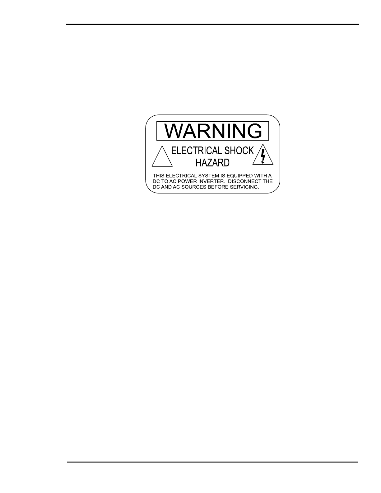
WARNING LA BEL
A warning label is provided to inform all per sonnel that an inverter is installed in your electrical system.
This label should be installed at the electric al panel that is being powered by the inverter. Be cautious until
the inverter is disconnected from your electrical system.
!
Figure 10, Warning Label
2001 Xantrex Technology, Inc.
5916 - 195th Street N. E.
Arlington, WA 98223
Telephone: 360/435-8826
Fax: 360/435-2229
www.traceengineering.com
SW Series Inverter/Charger
Part No. 2031-5
Rev. C: February 2001
Page
21
Page 30
INSTALLATION
SW Series Inverter/Charger
DC WIRING
CAUTION: The inverter’s maximum peak current requirements are high. If battery cables are too
small and/or connections are loose, efficiency and maximum output power are degraded. Small
cables or loose connections may cause dangerous overheating and a fire.
BATTERY CABLE SIZING
The larger the battery cables the better. Undersized cables result in additional s tres s on the inverter , lower
efficiency, reduced surge power and lower peak output voltage. Don’t use cables that are too small and
degrade the efficiency that we have worked so hard to achieve and you have paid so much to own.
Also, don’t use cables that are too long - the shorter the better. The lower the DC system voltage, the
shorter the cables need to be. If long cables ar e r equired, either overs ize them subs tantially, or switch to a
higher voltage system, such as 24 Vdc or 48 Vdc . On 12-Vdc system , cables m ay need to be doubled up
(paralleled) to get maximum performance from the inverter.
NOTE: Do not separate the positive and negative cables - taping them together in parallel is
best. This reduces the inductance of the wire r esulting in a better waveform and reduces the
current in the inverter’s filter capacitors. Make the battery cables as short as possible.
Although large cables may seem expensive, spending an additional $100 or more to ensure the
performance of your inverter is a wise investment. Using cables that are too small is like putting cheap
tires on a high performance sports car - the results will be disappointing.
If the system is expected to operate at the inverter ’s continuous power level rating for long periods of tim e
(over an hour), larger disconnects and cables may be required. Most systems do not operate at full
capacity for periods exceeding an hour and can operate satisfactorily with the following cable and
disconnects shown. If your system includes enorm ous batteries or has a very large DC source able to
continuously power the inverter (such as a hydroelectric plant, etc.) then increasing the disconnect and
cable sizes may be required to prevent nuisance tripping of a breaker or blowing of fuses.
The following table gives recom mended minimum cable sizes for various cable run lengths and inverter
voltages. Use only all copper cables. These recommendations may not meet all local code or NEC
requirements.
Table 2, Minimum Recommended Battery Cable Size vs. Cable Length
INVERTER
MODEL
SW2512 267 Amps 334 Amps #4/0 AWG/107 mm2#4/0 AWG/107 mm2Not Recommended
SW2612E 278 Amps 348 Amps #4/0 AWG/107 mm2#4/0 AWG/107 mm2Not Recommended
SW3024E or J 160 Amps 201 Amps #4/0 AWG/107 mm2#4/0 AWG/107 mm2#4/0 AWG/107 mm
SW4024 or W, K 214 Amps 267 Amps #4/0 AWG/107 mm2#4/0 AWG/107 mm2#4/0 AWG/107 mm
SW3048E or J 80 Amps 100 Amps #2/0 AWG/67.4 mm2#2/0 AWG/67.4 mm2#4/0 AWG/107 mm
SW4048 or K 107 Amps 134 Amps #2/0 AWG/67.4 mm2#2/0 AWG/67.4 mm2#4/0 AWG/107 mm
SW4548E or A 120 Amps 150 Amps #2/0 AWG/67.4 mm2#2/0 AWG/67.4 mm2#4/0 AWG/107 mm
SW5548 147 Amps 184 Amps #4/0 AWG/107 mm2#4/0 AWG/107 mm2#4/0 AWG/107 mm
1
TYPICAL DC AMPS is based on Low Battery Voltage with an efficiency of 85%.
2
NEC AMPS is based on Low Battery Voltage, an efficiency of 85%, and a 125% NEC de-rating.
TYPICAL
DC
1
AMPS
NEC
AMPS
2
1 TO 3 FEET
ONE WAY
3 TO 5 FT
ONE WAY
5 TO 10 FT
ONE WAY
2
2
2
2
2
2
WARNING! Battery cables that are too small will melt and burn the first time the inverter is
operated at high power levels.
Page
22
2001 Xantrex Technology, Inc.
5916 - 195th Street N. E.
Arlington, WA 98223
Telephone: 360/435-8826
Fax: 360/435-2229
www.traceengineering.com
Part No. 2031-5
Rev. C: February 2001
Page 31

INSTALLATION
DC DISCONNECT AND OVERCURRENT PROTECTION
For safety and to comply with regulations, battery over-current protection is required. Fuses and
disconnects must be s ized to protect the wiring in the system. The fuse or disconnect is required to open
before the wire reaches its maximum current carrying capability.
For residential and commercial electr ical systems, the National Electrical Code requir es both overcurrent
protection and a disconnect switch. These installation parts are not supplied as part of the inverter.
However, Xantrex offers a DC rated, UL listed, circuit breaker disconnect specifically designed for use
with Tr ac e™ inverter s for applic ations requiring NEC c ompliance. T wo amper age ratings are available - a
DC250 (250 amps) and a DC175 (175 am ps). Thes e disconnects are available in a s ingle or double pole
configuration to handle either one or two inverters. The DC disconnect enclosure will acc omm odate up to
four smaller break ers f or use as DC load dis connects, PV ar ray disconnects, etc. and the top is designed
to allow direct connection of up to two Xantrex charge controllers. The Trace™ DC disconnect is not
designed to accept doubled (paralleled) cables which may be required for long cable runs. Also, the plastic
red and black covers on the end of the inverter is not designed to accommodate dual cables. If dual
cables are used, the optional conduit box (SWCB) should be used.
When sizing the DC disconnect, the ex pec ted c ontinuous load on the inver ter is us ed to determine the DC
current involved. You must account for the efficiency loss through the inverter (see the POWER VS.
EFFICIENCY section on page 59 in this manual) which increases the DC current draw. Divide the
maximum continuous current draw by the lowest efficiency to determine the DC current, a 25% safety
margin should be included to comply with the code requirements. When a break er has been selected as
the overcurrent device, tighter sizing may be acceptable since the breaker is more easily reset when
compared to a high current, bolt-in type fuse.
Marine and RV installations typically do not require conduit or a means of disconnection, although
overcurrent protection (fus e) is r equired. Xantr ex of fers a fus eblock (TFB) that pr ovides the code required
inverter overcurrent protection for residential, commercial, RV and Marine applications.
TFB’s include a fast acting, current limiting class-T fuse to protect your battery, inverter and high
amperage cables from damage by short circuits and overloads. This fuse provides extremely fast
protection when a short circuit occurs . When properly selected, it also has a time delay that allows the
inverter to surge to full power without blowing the fuse. A slide off cover prevents accidental contact with
the fuse’s live terminals. For maxim um protection, install the fuseblock within 18 inches ( 45 cm) of the
battery. The fuses are available in 110, 200, 300, and 400 amp sizes.
Use Table 3 below, to determine the proper size disconnect ( breaker) or f use for the battery cables you
are using. These recom mendations may not meet all local code or the NEC requirem ents, consult your
applicable electrical code for more information regarding acceptable fuse and cable sizes.
Table 3, Battery Cable To Maximum Breaker/Fuse Size
CABLE SIZE
REQUIRED
RATING IN
CONDUIT
MAXIMUM
BREAKER SIZE
RATING IN
“FREE AIR”
MAXIMUM
FUSE SIZE
# 2 AWG 115 amps 125 amps* 170 amps 175 amps*
00 AWG 175 amps 175 amps 265 amps 300 amps*
0000 AWG 250 amps 250 amps 360 amps 400 amps*
*The NEC allows rounding up to the next standard fuse size from the cable rating, i.e. 150-amp cable size
rounds up to a standard 175-amp fuse or breaker size. The term "free air" is defined by the NEC as cabling that
is not enclosed in conduit or a raceway. Cables enclosed in raceways or conduits have substantially lower
continuous current carrying ability due to heating factors.
Contact your Xantrex dealer to order the inverter disconnects/fuses or see the OTHER PRODUCTS
section in this manual on page 129 for more information.
2001 Xantrex Technology, Inc.
5916 - 195th Street N. E.
Arlington, WA 98223
Telephone: 360/435-8826
Fax: 360/435-2229
www.traceengineering.com
SW Series Inverter/Charger
Part No. 2031-5
Rev. C: February 2001
Page
23
Page 32
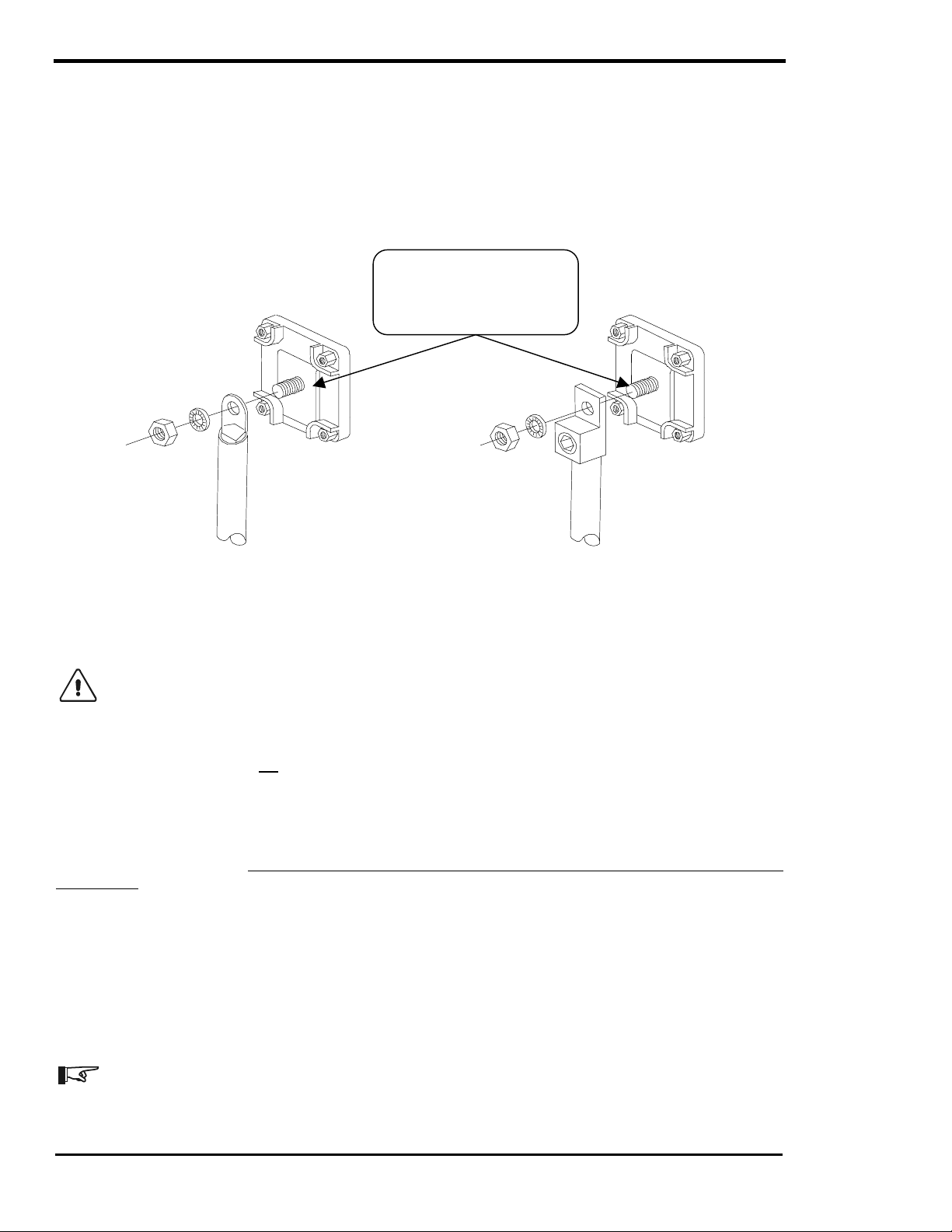
INSTALLATION
SW Series Inverter/Charger
BATTERY CABLE CONNECTIONS
Cables must have crimped (or preferably, soldered and crimped) copper compression lugs unless
aluminum mec hanical lugs are used. Soldered connections alone are not acc eptable. We suggest us ing
high quality, UL-listed Xantrex battery cables. These cables are available in a spec ific ass ortm ent of sizes
from 1-½ to 10 feet, and in 2/0 or 4/0 AWG. They are color-coded and have pressure-crimped, sealed-ring
terminals. Contact your Xantrex dealer to order. Figure 11, illustrates proper method to connect the battery
cables to the SW Series Inverter/Charger.
Do not place anything
between battery cable lug
and terminal surface.
Assemble exactly as shown.
2/0 Copper Compression Lug 2/0 Aluminum Mechanical Lug
Figure 11, Battery to Inverter Cable Connection
INSTALLATION PROCEDURE - BATTERY CABLES
CAUTION: THIS INVERTER IS NOT REVERSE POLARITY PROTECTED. If the positive
terminal of the battery is connected to the negative term inal of the inverter and vice vers a, the
result will be instantaneous failure of nearly every power transistor. This type of damage is
obvious and requires an extensive rebuilding of the inverter at your own cost. It is not c overed by
the warranty.
Ensure that the inverter is off bef ore connecting or disconnecting th e battery cables and that all
AC power is disconnected from the inverter’s inputs.
Determine the correct s ize battery cable to use for your installation from Table 2, on page 22 and the
proper size disconnect/fuse from Table 3, Battery Cable To Maximum Breaker/Fuse Size on page 23.
Color-code the cables with colored tape or heat shrink tubing [the standard colors ar e red for positive (+)
and black for negative (-)]. Always double-check the polarity with a voltmeter before mak ing the battery
connections
Install the over-current device (fuse or circuit breaker) between the inverter and battery - as close as
possible to the battery - in the ungrounded conductor [typically the positive (red) cable]. Connect a cable
from the battery negative terminal to the negative (black) terminal on the inverter.
Observe Battery Pola ri ty ! Place the battery cable ring terminals over the stud and directly against the inverter’s
battery terminals. Red is positive (+), Black is negative (-). Use a 1/2-inch wrench or socket to tighten the 5/16
SAE nut to 10-15 foot/pounds. Do not place anything betw een the cable ring terminal and t he flat metal
part of the terminal or overh eating of the terminal may occur. DO NOT APPLY ANY TYPE OF ANTIOXIDANT PASTE until after the battery cable wiring is tightened to 10–15 foot-pounds!
Note: Connecting the battery cables to the inverter battery ter minals may c ause a br ief s park or arc
- usually accompanied by a "snapping" sound. This is normal - don’t let it scare you. It is s imply the
internal capacitors of the inverter being charged.
Page
24
2001 Xantrex Technology, Inc.
5916 - 195th Street N. E.
Arlington, WA 98223
Telephone: 360/435-8826
Fax: 360/435-2229
www.traceengineering.com
Part No. 2031-5
Rev. C: February 2001
Page 33
INSTALLATION
CONTROL WIRING
More advanced installations will require additional wiring to interface the inver ter to other components of
the system. Proper installation is important to ensure the reliability of the system.
Although the circuits may carry little or even no actual power, the use of quality wire in conduit is
recommended to pr ovide good results. All circuits s hould also be fused at the sourc e of the power in the
circuit to provide both protection and indication of problem s with the control circ uit. Consult local c ode and
the NEC for minimum wire size and type required based on the length that you want to run.
The AC circuit board provides m ale type push on connectors and you are provided crim p-on term inals in
your hardwire package to connect to these Aux and Gen Control relays. These terminals allow easier
connection of a variety of wire sizes and allow faster installation and troubleshooting. T his circuit board
also includes two LED indicators to allow visual indication of the generator control s equence provided by
relays RY7 and RY8. These relays are not intended to directly control the starter motor or operate the
ignition system - rather they can be used to send a signal or operate the coil of another higher am perage
device which does the actual switching of the power.
CAUTION: A fuse rated at 5 amps or less must be included t o protect each of the relays.
Damage to these relays is not covered by the Warranty and requires the inverter to be returned to
a service center for repair.
GEN CONTROL WIRING
The configuration of the starting relays on all SW Series inverters allows st arting of both Honda and O nan
type generators. The COM terminals of relay RY7 and RY8 are separated and both the normally open and
normally closed contacts are provided.
It is much easier to m ake the connections to the generator if a remote control terminal or connector is
available on the generator. This som etimes requires that the generator optional remote c ontrol panel be
purchased. This allows examination of how the generator remote control panel work s - which is what the
inverter’s generator control system in the inverter must duplicate.
Connection of the inverter’s generator control r elays in the inverter to the generator’s r em ote control panel
also eliminates the need to make modifications and thus violate the generator’s warranty.
You should also ensure that there is a switch to allow disabling of the autom atic generator control system
at the generator. This will allow local control of the generator, preventing starting while servicing, etc.
AUX RELAY WIRING
The auxiliary relays are RY9, RY10, and RY11 and can be used to control external power sources or
loads. The voltage settings that determine when the relays are activated are individually adjustable. The
relays are connected to a terminal block located in the wiring compartment at the left end of the inverter
and must be fused to prevent dam age if they are miswired or a short- circuit occurs . The m aximum fuse
size must not exceed 5 amps and the f us es s hould be loc ated as c los e as pos s ible to the sour ce of power
e.g. generator battery.
REMOTE CONTROL WIRING
An optional remote control panel for the SW Series Inverter/Charger is available (Trace™ part num ber
SWRC or SWRC/50FT) which provides complete duplication of the control panel on the front of the
inverter. It is connected to the REMOTE PORT on the left side (AC side) of the inverter (s ee page 12 for
the location of the REMOTE PORT ) thr ough a pr ovided cable. Two cable lengths are available - 25 feet ( 8
meters) or 50 feet (16 meters). Distances longer than 50 feet (16 meters) are not recomm ended. The
remote control cable should be k ept away from sources of r adio frequency interference such as motors
and antennas. The cable must be protected from abrasion and hot surfaces.
2001 Xantrex Technology, Inc.
5916 - 195th Street N. E.
Arlington, WA 98223
Telephone: 360/435-8826
Fax: 360/435-2229
www.traceengineering.com
SW Series Inverter/Charger
Part No. 2031-5
Rev. C: February 2001
Page
25
Page 34

INSTALLATION
SW Series Inverter/Charger
SYSTEM GROUNDING
GROUNDING INSTRUCTIONS - This inverter/charger should be connected to a grounded, permanent
wiring system. For most installations, the negative battery conductor should be bonded to the grounding
system at one (and only one point) in the system. The subjec t is mor e easily discuss ed if it is divided into
three separate subjects; Chass is Ground, Ground Rods and Bonding. The grounding requirements vary
by country and application. All installations should comply with national and local codes and ordinances .
Even system designers and electricians often misunders tand system grounding. Consult loc al codes and
the NEC for specific requirements. Refer to Table 15, page 133 for safety ground wire sizes.
EQUIPMENT OR CHASSIS GROUNDS
This is the simplest part of grounding. The idea is to connect the metallic chassis of the various
enclosures together to have them at the same voltage potential, which reduces the possibility for electric
shock. It also provides a path f or fault currents to flow through to blow fus es or trip circuit breaker s. The
size of the connecting conductors should be coordinated with the size of the overc urrent devices involved.
Under some circumstances, the conduit and enclosures themselves will provide the current paths.
GROUNDING ELECTRODES/GROUND RODS
The purpose of the grounding electrode (often called a ground rod) is to “bleed” off any electrical charge
that may accumulate in the electrical system and to provide a path for “induced electromagnetic energy” or
lightning to be dissipated. The size for the conductor to the grounding electrode or gr ounding system is
usually based on the size of the largest conductor in the system. Mos t s ystems use a 5/8” (16 mm) copper
plated rod 6 feet (2 meters) long driven into the earth as grounding electrode. It is also com mon to use
copper wire placed in the concrete foundation of the building as a grounding system. Either method m ay
be acceptable, but the local code will prevail. Connection to the ground electrode should be done with
special clamps located above ground where they can be periodically inspected.
Many large systems use multiple ground rods. The most com m on exam ple is providing a direct path f rom
the solar array to earth near the location of the solar array. Most electrical codes want to see the multiple
ground rods connected by a separate wire with its own set of clamps. If this is done, it is a good idea to
make the connection with a bare wire located outside of the conduit (if us ed) in a tr enc h. T he r un of buried
wire may be a better grounding electrode than the ground rods! Well casings and water pipes can also be
used as grounding electrodes. Under no circ umstance should a gas pipe or line be used. Consult local
codes and the NEC for more information.
BONDING THE GROUNDING SYSTEM
This is the most confusing part of grounding. The idea is to connect one of the current carrying conductors
(usually the AC neutral and DC negative) to the grounding system. This connection is why we call one of
the wires “neutral” in the North American type electrical systems. You can touch this wire and the
grounding system and not be shocked. When the other ungrounded conductor (the hot or positive)
touches the grounding system, current will flow through it to the point of connection to the grounded
conductor and back to the sourc e. This will cause the overcurrent protection to stop the flow of current,
protecting the system. This point of connection between the grounding system (ground rod, vehicle
frame, boat hull, etc.), the cur rent carrying grounded conductor (AC neutral and DC negative), and the
equipment grounding conductor (green ground wire, equipment ground) is often called a “bond”. It is
usually located in the overcurrent protection device enclosures (both AC and DC) . Although it c an be done
at the inverter, codes do not generally allow it since the inverter is considered a “serviceable” item that
may be removed from the system. In residential systems, it is located at the service entranc e panel, after
the power has gone through the kilowatt-hour meter of the utility. In mobile applications (RV and m arine)
this “bond” is provided by the different AC sources on board, see NEUTRAL-TO-GROUND BOND
SWITCHING (RV AND MARINE APPLICATIONS) on page 27.
Bonding must be done at only one point in an electrical system. Our systems inherently have two separate
electric systems - a DC system and an AC s ystem. This means that two bonding points will occur in all
inverter applications. The bonding point will also be connected to the equipment (chassis) grounding
conductors. It is common to have two separate conductors connect the ground electrode and the two
bonding points. Each conductor should use a separate clamp.
Page
26
2001 Xantrex Technology, Inc.
5916 - 195th Street N. E.
Arlington, WA 98223
Telephone: 360/435-8826
Fax: 360/435-2229
www.traceengineering.com
Part No. 2031-5
Rev. C: February 2001
Page 35
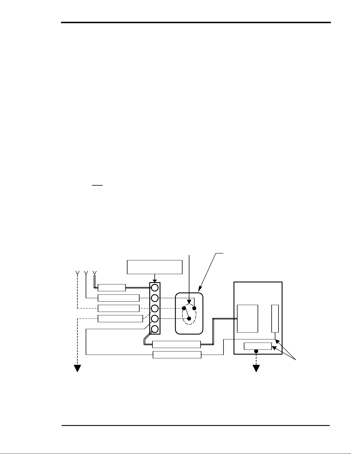
INSTALLATION
RY1
In some countries, the neutral is not bonded to the grounding system. This means you may not know
when a fault has occurred since the overc ur rent devic e will not tr ip unles s a “double” fault occurs. In some
marine electrical codes, this type of system is used.
NEUTRAL-TO-GROUND BOND SWITCHING (RV AND MARINE APPLICATIONS)
As required by NEC code and UL specification 458, inverter/char ger installations in the U.S. that ar e used
in RV or Marine applications employ ground-to-neutral switching. T he purpose for this requirement is to
ensure that all the neutral conductors are connec ted (“bonded”) to a single ground point in a three-wire
(hot, neutral and ground) AC system. This prevents a voltage difference from developing between the
vehicle/boat’s AC neutral and the external AC source’s (generator or shore power) neutral, which may
cause an electric shock or cause nuisanc e tripping of GFI’s. The SW Series In verter/Charger does not
include Neutral-to-Ground switching and must be provided in the AC installation.
When the unit is oper ating as an inverter, the AC output neutral should be connected or “bonded” to the
frame/hull (chas sis ground). W hen an external AC source (AC shore c ord) is provided, the inverter’s AC
output neutral should be disconnected from the frame/hull (chassis ground) and allow the “bond” to be
provided by the external AC source. The requirement to switch the neutral c an be met by your inverter
internally or can be easily met by using an external relay to connect and disconnect the external AC
source’s neutral. If another AC sourc e (on-board generator) is included in the RV or boat, this AC sour ce
neutral is required to be connected to ground when it is being used, and to disconnec t all other neutrals
from ground. An AC transfer switch can be used if it switches both the shore cords and generators neutral.
In some marine applic ations, neutral-to-ground switching is not required or acceptable. T he potential for
galvanic corrosion caused by small leak age c urrents between boats with dissim ilar m etals is pres ent. T he
proper and safe ways to prevent this is by using galvanic isolators or include an isolation trans former f or
the AC input. Disconnecting the common ground between the AC and DC system could contribute
to a hazardous and potentially fatal situation.
The figures below graphically describes the neutral-to-ground switching system for the two cases in
question: the unit operating as an inverter feeding the AC subpanel, and the unit connected to an external
AC source (generator, shore power, etc.).
No external AC
source is present
AC HOT IN
AC NEUTRAL IN
EARTH GROUND
CHASSIS GROUND
NEUTRAL-TO-GROUND
“BOND” is provided by this relay
for the entire AC system
INVERTER
(AC Terminal Block)
AC HOT OUT
AC NEUTRAL OUT
NEUTRAL-TO-GROUND SWITCHING
RELAY (provided in the AC installation):
Connects the output neutral to chassis or
vehicle ground when AC is not present at
inverter input. This assures all equipment in
the vehicle is referenced to the same
ground.
AC PANEL
(RV/Marine)
HOT
NEUTRAL
GROUND
The neutral conductor should
not be connected to the
equipment grounding
conductors or enclosures.
Figure 12, Neutral-To-Ground Bond Switching: No External AC Source Connected
2001 Xantrex Technology, Inc.
5916 - 195th Street N. E.
Arlington, WA 98223
Telephone: 360/435-8826
Fax: 360/435-2229
www.traceengineering.com
SW Series Inverter/Charger
Rev. C: February 2001
Part No. 2031-5
Page
27
Page 36
INSTALLATION
SW Series Inverter/Charger
AC SOURCE
AC NEUTRAL IN
EARTH GROUND
CHASSIS GROUND
NEUTRAL-TO-GROUND “BOND” is
provided by an external AC source for
the entire AC system
INVERTER
(AC Terminal Block)
AC HOT IN
RY1
NEUTRAL-TO-GROUND SWITCHING RELAY
(Provided in the AC installation): Connects the
neutral from external AC source, and neutral of
the AC panel loads together when AC is applied
to the inverter input.
AC PANEL
(RV/Marine)
HOT
The neutral conductor
should not be
NEUTRAL
connected to the
equipment grounding
conductors or
enclosures.
AC HOT OUT
AC NEUTRAL OUT
GROUND
Figure 13, Neutral-To-Ground Bond Switching: External AC Source Connected
Figure 14, graphically shows the current path if no ground switching was employed in a multiple AC
source system. If one neutral was tied to the AC subpanel ground buss and another neutral tied to the
vehicle or chassis ground, the two different ground points would now form a current car rying conductor
with the frame/hull (chassis ground) acting as the “wire” between the two different ground points. This
means any ground point in the vehicle or boat becomes a potential current carrying conductor, which
could result in an electric shock . Any form of Ground Fault Circuit Interrupter (GFCI) such as those found
in bathroom outlets, will pop if a ground loop (a s ituation where a voltage difference exist between m ultiple
ground points) is created.
If, however, the ground switching system were in place, it would ensure that there is only one ground point
in the system at all times. Th is would be either the vehicle/boat ground or the exter nal AC source ground,
but never both at once.
GFI’s will
nuisance trip
with multiple
Neutral-to-
Ground bonds
AC SOURCE
GFI
AC NEUTRAL IN
EARTH GROUND
CHASSIS GROUND
NEUTRAL-TO-GROUND
“BOND” is provided by
the external AC source
INVERTER
(AC Terminal Block)
AC HOT IN
RY1
AC HOT OUT
AC NEUTRAL OUT
NEUTRAL-TO-GROUND SWITCHING RELAY
(Provided in the AC installation): Connects the
neutral from external AC source, and neutral of
the inverter output (AC panel loads) together
when AC is applied to inverter input.
AC PANEL
(RV/Marine)
HOT
Another NEUTRAL-
TO-GROUND
“BOND” is
incorrectly provided
in the AC panel.
NEUTRAL
The neutral
conductor should
not be connected to
GROUND
the equipment
grounding
conductors or
enclosures.
Figure 14, Neutral-To-Ground Bond Switching: Neutral Bonded To Ground
Page
28
2001 Xantrex Technology, Inc.
5916 - 195th Street N. E.
Arlington, WA 98223
Telephone: 360/435-8826
Fax: 360/435-2229
www.traceengineering.com
Part No. 2031-5
Rev. C: February 2001
Page 37
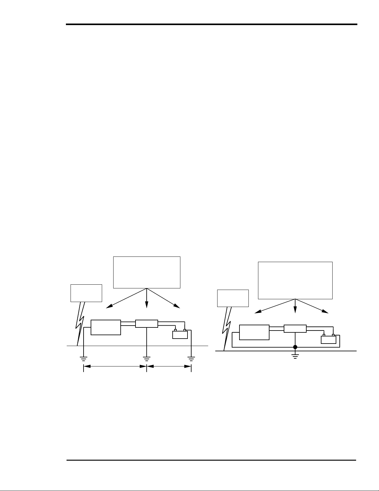
INSTALLATION
across Component Grounds
GROUNDING VS. LIGHTNING
This information is intended to provide bas ic grounding techniques that will help prevent inverter dam age
due to lightning. It is not intended to be a complete course on grounding or a guarantee against protection
during a lightning strike situation. The NEC is the ultimate authority as to legitimate gr ounding techniques
for your electrical system.
If an electrical system has com ponents gr ounded at differ ent points in the earth, large voltage dif ferences
will exist between these points during a lightning strike (See Figure 15). If this voltage appears between
the AC and DC side of the inverter, it will fail. All T race™ inverters are designed to withstand a minim um
of 1750 volts between AC and ground, and 500 volts between DC and ground.
ONE GROUND FOR ALL EQUIPMENT
The first step in inverter protection is to make sure that all equipment in the system is physically
grounded at the same location. This ass ures that ther e is no voltage potential between grounds in the
system (See Figure 15 and Figure 16). No voltage means no current flow through the system.
Practically speaking, this would mean connecting the generator and batter y grounds together, as well
as the case or “safety” grounds in the system, and then attaching all to the sam e earth grounding rod
(See the NEC for specific information on grounding requirements, and hardware).
In severe conditions, the generator frame should physically be isolated from the earth by a wood
frame or some other insulating means. This assures that the single point ground system is
maintained.
KEEP EQUIPMENT CLOSE TOGETHER
All equipment involved in a system should physically be located as close as possible to one another.
This reduces the potential that is developed between the ground site and the individual components of
the system during a lightning strike. This single point grounding greatly reduces the potential for
lightning damage to electrical equipment.
If you are unable to achieve single-point grounding due to large distances between equipm ent or other
variables, other means of lightning protection must be considered. Consult a reputable lightning
protection company.
Equipment acts as a
Equipment all grounded at
same point. No voltage
across system, and no
current flow through
equipment and wiring.
Lightning
Strike
conductor due to
voltage between the
grounds. Bad!
Lightning
Strike
GENERATOR INVERTER BATTERY
Generator
Ground
Difference
Inverter
Ground
Voltage
BANK
Battery
Ground
Voltage
Difference
GENERATOR INVERTER BATTERY
Generator
Ground
Inverter
Ground
Zero Voltage Difference
BANK
Battery
Ground
Figure 15, Multiple Point Ground System Figure 16, Single Point Ground System
2001 Xantrex Technology, Inc.
5916 - 195th Street N. E.
Arlington, WA 98223
Telephone: 360/435-8826
Fax: 360/435-2229
www.traceengineering.com
SW Series Inverter/Charger
Part No. 2031-5
Rev. C: February 2001
Page
29
Page 38

INSTALLATION
SW Series Inverter/Charger
Page
30
2001 Xantrex Technology, Inc.
5916 - 195th Street N. E.
Arlington, WA 98223
Telephone: 360/435-8826
Fax: 360/435-2229
www.traceengineering.com
Part No. 2031-5
Rev. C: February 2001
Page 39

FUNCTIONAL TEST
FUNCTIONAL TEST
Once the AC and DC wiring have been installed and connected, take a moment to go back over all
connections and mak e sure they are secure and have been installed pr operly. Ensure that there is no AC
or DC power provided to the inverter/charger and that all AC loads are disconnected from the output of the
inverter.
The below steps will complete a functional test of the inverter. If any area fails, figure out why before
proceeding. The TROUBLESHOOTING GUIDE section, starting on page 112, will hopefully help solve
problems you may encounter.
1. After ensuring the correct polarity, apply battery (DC) power to the inverter by turning on the battery
bank DC disconnect or connecting the pr oper fuse inline to the batter y to complete the battery circuit.
The inverter will power up, the LCD display will be on, but the inverter will remain in the OFF mode.
2. Press the red ON/OFF MENU switch twice (SEARCH then ON) to turn the inverter on.
Monitor your INVERTING LED (Yellow) to ensure what mode you are in:
• Off – The Inverter/Charger is off. This is the default position of the inverter upon power-up. No
inverter or pass-thru power will be applied to the AC loads.
• One blink/sec – The Inverter/Charger is in the Search mode and is looking for an AC load greater
than the SEARCH WATTS setting (default = 16 watts).
• On – Indicates the Inverter/Charger is on. The inverter will produce a low audible “buzz” is able to
provide power to the AC loads.
If the inverter does not produce an low audible “buzz” or come on, check all connections. Check the
inverter’s DC voltage on the positive (+) and negative (–) terminals. If the DC voltage is low, the
battery bank needs to be charged externally. Charge the battery bank and restart the functional test.
3. W ith the inverter ON, check the AC voltage on the AC output term inal of the inverter and ensure you
get the correct AC voltage for your particular unit. After confirming the corr ect AC voltage, connect
your AC output breaker and place a load on the inverter (plug in a light or other load to an outlet the
inverter is powering), and make sure it works.
4. Check your battery charger. To charge your batteries, provide AC power - by plugging in a power
cord or turning on the AC input breaker - to the AC HOT IN 1 and NEUTRAL IN 1 terminals on the
inverter. The AC1 IN GOOD (Green) light will initially blink until AC power has synchronized and then
turn solid to indicate the AC power is getting to the inverter. After a minimum 20 s econd delay, the
Battery BULK LED (Yellow) or FLOAT LED (Green) on the inverter should be on. This indicates the
charger is working properly. The Control Panel lights should indicate which charge stage (bulk or float)
the inverter is currently in. Any AC loads powered by the inverter should also work at this point s inc e a
portion of the AC input power (Utility or Generator) is passed through the inverter to power the loads.
5. Disconnect AC power. Take away the AC input power by turning the AC power breaker off, or
unplugging the AC power cord. The inverter should transfer to inverter mode immediately. The
INVERT (yellow) LED coming on will indicate this. The inverter will begin to produce an low audible
“buzz” as it takes power from the batteries and uses it to power the loads. The loads s hould continue
to operate uninterrupted.
6. This completes the functional test, if all areas pass, the inverter is ready for use. If any of the inverter’s
internal setpoints are to be adjusted, consult the MENU SYSTEM section starting on page 33.
2001 Xantrex Technology, Inc.
5916 - 195th Street N. E.
Arlington, WA 98223
Telephone: 360/435-8826
Fax: 360/435-2229
www.traceengineering.com
SW Series Inverter/Charger
Part No. 2031-5
Rev. C: February 2001
Page
31
Page 40
FUNCTIONAL TEST
SW Series Inverter/Charger
Page
32
2001 Xantrex Technology, Inc.
5916 - 195th Street N. E.
Arlington, WA 98223
Telephone: 360/435-8826
Fax: 360/435-2229
www.traceengineering.com
Part No. 2031-5
Rev. C: February 2001
Page 41

MENU SYSTEM
MENU SYSTEM
OVERVIEW
The operation of the inverter is determined by the settings in the menu system. The menu system is
divided into a USER MENU and a SETUP MENU. Each of the menu systems is divided into MENU
HEADINGS and MENU ITEMS. The menu headings break the m enu into groups of related menu item s.
At the Menu Item level a setting can be adjusted, a mode can be selected or information can be displayed.
When a num ber is included with the graphic of the m enu heading or m enu item in this m anual, the values
shown are the default value and are for a 12-volt domestic (120VAC/60Hz) model SW Series
Inverter/Charger. For 24 volt systems multiply the DC settings shown by 2, for 48 volt systems multiply the
DC settings shown by 4.
• The USER MENU provides the contr ols and settings needed on a daily basis. It allows you to turn on
the inverter and generator, read the AC and DC meters , check on an error cause and even adjus ts
the inverter’s time clock.
• The SETUP MENU provides all of the settings required to configure the inverter to operate in the
necessary modes for your installation. They are separated from the USER MENU to reduce tampering
and simplify the daily operation of the inverter.
The SW Series Inverter/Charger MENU SYSTEM is accessed through the CONTROL PANEL on the front
of the unit. To access the SETUP MENU, press both the red ON/OFF MENU and green GEN MENU
buttons at the same time once. The display will show INVERTER SETUP (9). This is simply the
continuation of the same m enu system of the USER MENU. If you select a menu heading less than nine,
or press either the red or green buttons, you will have to re-enter the setup menu by pressing the red and
green buttons at the same time again.
2001 Xantrex Technology, Inc.
5916 - 195th Street N. E.
Arlington, WA 98223
Telephone: 360/435-8826
Fax: 360/435-2229
www.traceengineering.com
SW Series Inverter/Charger
Part No. 2031-5
Rev. C: February 2001
Page
33
Page 42

MENU SYSTEM
SW Series Inverter/Charger
USER MENU MAP
Menu Heading
Menu Item
Information
Inverter Mode
Set Inverter
OFF SRCH ON CHG
CHG avail. Only
in FLT mode.
Press red or
setpoint button
to move.
Move cursor to
Inverter OFF to
resetOverCurrent
Setpoint
The values shown are the factory default val ues for
Model SW2512.
See the USER and SETUP m enu i tem descriptions
for default values for other models.
MENU HEADINGS
Generator Mode
1
Set Generator
OFF AUTO ON EQ
Gen under/over
speed NO
Generator start
error NO
Generator sync
error NO
Gen max run time
error NO
Load Amp Start
Ready NO
Voltage Start
Ready NO
Exercise Start
Ready NO
Move cursor to
GEN OFF to reset
Generator error. AC1 & AC2 volts
If no start in 5
trys then error.
If Gen starts &
runs for 5 min
then stops the
inverter will
not attempt
restart until
gen auto start
conditions are
again satisfied. for float, bulk, eq
If Gen runs for
More than max
Run time then
Error.
Under/Over speed
Will cause a
Sync error in 10
minutes
Trace
2
Engineering 3
Press reset now
for defaults
Revision 4.01 Input amps AC
5916 195th St NE
Arlington, WA
98223 USA Battery actual
Ph 360-435-8826
Fax 360-435-2229
Meters
Inverter/charger
Amps AC 00
Load
amps AC 00
volts DC 12.6
Battery TempComp
volts DC 12.6
Inverter
volts AC 00
Grid (AC1)
volts AC 00
Generator (AC2)
volts AC 00
Read Frequency
Hertz 60
valid only when
inverter synced
to that input.
Batt volt actual
is used for
LBCO,HBCO,LBX,
LBCI,sell volts,
and gen starting gen will always
Batt volt temp
comp is used,
& aux relays
Error Causes
4
Over Current
Transformer
00
overtemp NO
Heatsink
overtemp NO
High Battery
voltage NO
Low Battery
voltage NO
Inverter breaker
tripped NO
AC source wired
to output NO
External error
(stacked) NO
Generator start
error NO
Generator sync
error NO
Gen max run time
error NO
Gen under/over
speed NO
Inverter breaker
tripped NO
Push buttons on
Control Panel
Time of Day
5
00:00:00 6
Set Clock hour
NO
00:00:00
Set Clock minute
00:00:00
Set Clock second
Generator Timer
Start Quiet
Time h:m 08:00
End Quiet
Time h:m 08:00
Gen doesn’t run
During quiet
time unless batt
volts is less.
than LBCO volts
for 30 seconds.
To defeat timers
set start = end.
If exercise day
set to 1 then
start @ endquiet
End User Menu
8
00
7
MENU ITEMS
Page
34
2001 Xantrex Technology, Inc.
5916 - 195th Street N. E.
Arlington, WA 98223
Telephone: 360/435-8826
Fax: 360/435-2229
www.traceengineering.com
Part No. 2031-5
Rev. C: February 2001
Page 43

MENU SYSTEM
SETUP MENU MAP
The SETUP MENU provides all t he controls and settings need ed when installing or adjusting the
system. To access the SETUP MENU, press both the red ON/OFF MENU and green GEN MENU buttons
on the Control Panel at the same time. To exit the SETUP MENU, press the red ON/OFF MENU button or
press the down MENU HEADING button until you reach the USER MENU (menu headings 1-8).
MENU HEADINGS
Inverter Setup
Set Grid Usage
FLT SELL SLT LBX
Set Low battery
cut out VDC 11.0
Set LBCO delay
minutes 10
Set Low battery
cut in VDC 13.0
Set High battery
cut out VDC 16.0
Set search
watts 48
Set search
MENU ITEMS
spacing 59
Bulk Charge
Trigger Timer 15
Set Start Bulk
time 00:00
To disable timer
set to 00:00
If grid timer
active set bulk
time after start
charge time.
In SLT mode don’t
disable this
timer. It is the
daily chg time.
Battery Charging10AC Inputs
9
Set Bulk
volts DC 14.4
Set Absorption
time h:m 02:00
Set Float
volts DC 13.4
Set Equalize
volts DC 14.4
Set Equalize
time h:m 02:00
Set Max Charge
amps AC 20
Set Temp Comp
LeadAcid NiCad
Low Battery
Transfer (LBX) 16
Set Low Battery
TransferVDC 11.3
Set Low battery
cut in VDC 13.0
See menu 9 to
enable LBX mode.
Make sure LBX is
above LBCO volts.
Gen Auto Start
11
setup 12
Set Grid (AC1)
amps AC 60
Set Gen (AC2)
amps AC 30
Set Input lower
limit VAC 108
Set Input upper
limit VAC 132
Battery Selling17Grid Usage Timer18Information file
Set Battery Sell
volts DC 13.4
Set Max Sell
amps AC 30
See menu 9 to
enable SELL mode.
Make sure LBX is
above LBCO volts.
Set Load Start
amp AC 20
Set Load Start
delay min 5.0
Set Load Stop
delay min 5.0
Set 24 hr start
volts DC 12.3
Set 2 hr start
volts DC 11.8
Set 15 min start
volts DC 11.3
Read LBCO 30 sec
start VDC 11.0
Set Exercise
period days 30
Set Maximum run
time h:m 08:00
Set Max Run time
to 0 to defeat.
Set Exercise to 0
to defeat.
See menu 9 to
to set LBCO.
Start Charge
time 21:00
End Charge
time 21:00
After Start
Charge time:
SELL mode
charges battery.
FLT mode
charges battery
After End Charge
time:
SELL mode sells
battery to AC1.
FLT mode drops
AC1 and inverts
Timer on when
start < > end;
timer off when
start = end
Sell and float
modes use timer
SLT and LBX mode
ignore timer
Gen starting
details 13
Set RY7 Function
GlowStop Run
Set Gen warmup
seconds 60
Set Pre Crank
seconds 10
Set Max Cranking
seconds 10
Set Post Crank
seconds 30
battery 19
Batt temp comp
changes battery
voltage reading
away from actual
HBCO resets at:
6v/48, 3v/24 and
1.5v/12v under
HBCO.
LowBattTransfer
used in LBX, FLT
Modes only. Goes
back to battery
at LowBattCutIn
(aka LBCI).
For LBX mode set
below LBCI so
charger won’t
cycle batteries
up and down and
set LBCO below.
Auxiliary Relays
R9 R10 R11 14
Set Relay 9
volts DC 14.5
R9 Hysteresis
volts DC 01.0
Set Relay 10
volts DC 14.8
R10 Hysteresis
volts DC 01.0
Set Relay 11
volts DC 15.0
R11 Hysteresis
volts DC 01.0
Close on batt >
setpoint.
Open on batt <
setpoint - Hys
Relays have 2
second delay on
Close, 0.1 sec
delay on open
End Setup Menu
20
2001 Xantrex Technology, Inc.
5916 - 195th Street N. E.
Arlington, WA 98223
Telephone: 360/435-8826
Fax: 360/435-2229
www.traceengineering.com
SW Series Inverter/Charger
Part No. 2031-5
Rev. C: February 2001
Page
35
Page 44

MENU SYSTEM
SW Series Inverter/Charger
LBCO 30 sec start
USER MENU
The USER MENU provides all the controls and settings needed on a daily basis. It allows you to turn on
the inverter and generator, read the AC and DC meters, check on an error cause and even adjus t the
inverter’s time clock.
MENU HEADINGS
Inverter Mode
Generator Mode
Trace
Engineering 3
Meters
Error Causes
Time of Day
Allows control of the inverter and enables the search and charger only
1
modes.
Allows control of the generator, enables autom atic operation or triggers an
2
equalization charge cycle. This menu heading is used only if a gener ator is
included and controlled by the inverter.
Provides information for accessing Xantrex. Also provides the software
revision number and allows resetting to the factory default values.
Allows monitoring of the DC battery voltage, AC voltages and AC current of
4
the inverter and other AC sources.
Provides an indication of the cause of an error c ondition. Check this menu
5
heading if the red ERROR LED indicator is illuminated on the control panel.
Sets the internal 24-hour clock. This is used for time sensitive operating
6
modes and to determine the “quiet time” period for generator run lockout.
Generator Timer
End User Menu
Used to set a run lockout period called “quiet tim e”. During quiet time, the
7
generator starts only if the battery voltage reaches the
VDC setting.
Used to display that you have reached the end of the USER MENU.
8
Page
36
2001 Xantrex Technology, Inc.
5916 - 195th Street N. E.
Arlington, WA 98223
Telephone: 360/435-8826
Fax: 360/435-2229
www.traceengineering.com
Part No. 2031-5
Rev. C: February 2001
Page 45

MENU SYSTEM
INVERTER MODE (1) MENU HEADING
Set Inverter
OFF SRCH ON CHG
Allows turning the inverter ON and OFF, enabling the SEARCH mode or selecting the char ger only mode
CHG. The inverter always starts in the OFF position when powered up. Pressing the red ON/OFF MENU
button on the control panel can also access this display. Use the SET POINTS button to move the s ingle
space cursor under the desired s elec tion or you can continue to pus h the r ed button to move the cursor to
the right.
• OFF - Disables the inverter. When the OFF position is selected, no power will be provided to the AC
loads even if an AC source is available. This is the default position of the inverter upon power-up.
• SRCH - Enables the automatic load search mode control system. This system will turn on the
inverter if a large enough load is connected. If not enough AC loads are detected, the INVERTING
LED will blink slowly. The required AC load level is adjustable in the INVERTER SETUP (9) menu
heading of the SETUP MENU.
• ON - Allows the inverter to provid e AC voltage to th e output an d energiz e the AC loads eit her
from the battery or any “synchronized” AC source available on the input. This position must be
manually selected.
• CHG - Allows the inverter to op erate only as a battery ch arger. AC power will be available to the
AC loads only if an AC source is available and “synchronized”. This mode is used to prevent
discharge of the batteries by the AC loads when a utility outage occurs. This mode is only operational
on the AC1 input and when the SET GRID USAGE menu item under the INVERTER SETUP (9)
menu heading is in the FLT mode. W hen a different mode under the INVERTER SETUP (9) menu
heading is selected, this position will be locked out. Selecting the ‘CHG’ mode will disable the
Automatic Generator control features.
INFORMATION DISPLAY
The following information is displayed as additional Menu Items.
CHG Avail. Only in FLT mode. Press red or setpoint button to move.
Move cursor to Inverter OFF to reset Overcurrent
GENERATOR MODE (2) MENU HEADING
Set Generator
OFF AUTO ON EQ
Allows the generator to be turned ON and OFF or enables AUTO-matic and EQualization operation. This
menu display always starts in the OFF position when the inverter is powered up. Pressing the green GEN
MENU button on the control panel can access this display. Use the SET POINTS button to move the
single space cursor under the desired selection. You can also push the green button again to m ove the
cursor to the right.
• OFF - Disables the ‘auto start’ system or turns of f a generator that has been started by the
inverter. Also resets the automatic generator control system after an ERROR condition has occurred.
• AUTO - Enables the automatic generator control feat ures. When the battery voltage or load am ps
reach the auto start settings for the r equired tim e period, the gener ator will be started unles s the tim er is
in the “quiet time” period. The generator will only start if the SET LOW BATTERY CUT OUT VDC setting
under the INVERTER SETUP (9) menu heading is reached for over 30 seconds continuously. If the
generator is started automatic ally based on battery voltage, the generator will shut off automatically once
the battery has completed the BULK and ABSORPTION stages of the battery charging process. If the
generator is started automatic ally based on load amps, as set in under the GEN AUTO START SETUP
(12) m enu heading, the generator will turn off once the load cur rent has decreased below the LOAD
START AMPS continuously for the LOAD STOP DELAY MIN period. The AUTO-matic generator control
operation is disabled if the ‘CHG’ mode under INVERTER MODE (1) menu heading is selected.
2001 Xantrex Technology, Inc.
5916 - 195th Street N. E.
Arlington, WA 98223
Telephone: 360/435-8826
Fax: 360/435-2229
www.traceengineering.com
SW Series Inverter/Charger
Part No. 2031-5
Rev. C: February 2001
Page
37
Page 46

MENU SYSTEM
SW Series Inverter/Charger
• ON - Starts the generator that is controlled by the inverter. If this position is selected, it will
manually turn on the generator that is connected to the GEN CONTROL relays. The OFF position
must be selected to manually turn the generator off.
• EQ - Triggers the battery charger to complete the equalization process. If an AC source is
connected to the AC HOT IN 1 terminals, then the equalization process will begin. If no AC sourc e is
connected to the AC HOT IN 1 terminals, then the generator will start the equalization process the
next time the generator is automatic ally started. Once the equalization process has been completed,
the cursor will return to the AUTO position. If you are battery charging - in FLOAT charge - from the
Utility or a manually controlled generator, you may initiate another BULK charge by moving the cursor
through EQ.
Gen under/over
speed NO
If YES is displayed, it indicates that the automatic generator control system has detected that the
generator frequency is with in acceptable tolerance, but is not well adjusted. This error condition will cause
the red ERROR LED to blink , but will not cause the automatic gener ator control system to shut down the
generator.
The ERROR LED can be used to indicate when the generator frequency is well adjusted. When the
frequency is within is within 3 hertz of the nominal value (57 to 63 for 60 Hz units, 47 to 53 for 50 Hz units),
the LED will be off. Once outside this window, the LED will blink slowly. A frequency meter is also provided
in the METERS (4) menu heading to allow a more precise adjustment of the generator. It is able to
indicate the frequency of the generator only after the inverter has been able to synchronize to the
generator. The acceptable frequency range for the SW Series is 53 to 67 Hertz for 60-Hertz m odels and
44 to 56 Hertz for 50-Hertz models.
Generator start
error NO
If YES is displayed, it indicates that the automatic generator control system was not able to successfully
start the generator. The system com pletes five start cycles and requires that the gener ator operate for a
minimum of 5 m inutes before the s tarting attem pts counter is cleared. T o m anually clear this error, select
OFF and then AUTO or ON from the SET GENERATOR menu item, which can also be accessed by
pressing the green GEN MENU button on the control panel.
Generator sync
error NO
If YES is displayed, it indicates that the automatic generator control system was not able to successfully
connect to the generator after it was running. If the gener ator runs f or 10 minutes without operating in the
AC voltage and frequency tolerance windows, then the automatic control system stops the generator and
indicates an error condition. To m anually clear this error, s elect OFF and then AUTO or ON from the SET
GENERATOR menu item, which can also be acces sed by pressing the green GEN MENU button on the
control panel.
Gen max run time
error NO
If YES is displayed, it indicates that the generator ran for a period of tim e that exceeded the SET MAX
RUN TIME menu item setting under the GEN AUTO START SETUP (12) menu heading. This error
indication will only light to let the user know that the generator ran longer than originally expected. This
may be caused by many variables such as; excessive AC or DC loads oper ating while the generator is
trying to charge the battery; the generator operating near the INPUT LOWER LIMIT VAC setting; or the
batteries no longer holding a charge. This error LED is an advisory indication only and will not allow the
inverter to stop the generator. To disable the MAX RUN TIME, set the time to zero. To manually clear this
error, select OFF and then AUTO or ON from the SET GENERATOR menu item, which can also be
accessed by pressing the green GEN MENU button on the control panel.
Page
38
2001 Xantrex Technology, Inc.
5916 - 195th Street N. E.
Arlington, WA 98223
Telephone: 360/435-8826
Fax: 360/435-2229
www.traceengineering.com
Part No. 2031-5
Rev. C: February 2001
Page 47

MENU SYSTEM
Load Start Amps
Ready NO
If YES is displayed, it indicates that the automatic control system has started or is about to start the
generator because the AC load current has reached the LOAD START AMPS setting. The automatic start
is delayed by the time period set by the LOAD START DELAY MIN setting in the GEN AUTO START
SETUP (12). This allows checking why the generator was automatically started.
Voltage Start
Ready NO
If YES is displayed, it indicates that the automatic control system has started or is about to start the
generator because the DC battery voltage reached one of the START VOLTS settings. The automatic
start is delayed by the time period of the START VOLTS setting involved in the GEN AUTO START
SETUP (12). This allows checking why the generator was automatically started.
Exercise Start
Ready NO
If YES is displayed, it indicates that the automatic control system has started or is about to start the
generator because the EXERCISE PERIOD DAYS setting has been reached. This allows c hecking of why
the generator was automatically started.
INFORMATION DISPLAY
The following information is displayed as additional Menu Items.
Move cursor to GEN OFF to reset Generator error. If no start in 5 trys then error.
If Gen starts & runs for 5 min then stops the inverter will not attempt restart until gen auto
start conditions are again satisfied. If Gen r uns for more than max run time then error.
Under/Over speed will cause a Sync error in 10 minutes.
TRACE ENGINEERING (3) MENU HEADING
Press reset now
for defaults
Allows resetting of all menu item settings to the factory default values. This also occurs when the battery is
disconnected from the inverter. The RESET TO FACTORY DEFAULTS button on the control panel will
only reset the default values if it is pressed while this menu item is displayed. All factory default settings
will be reset except for the TIME OF DAY (6) clock.
If the RESET TO FACTORY DEFAULTS button is pressed while in any other menu item or menu
heading, only the control panel display (and remote c ontrol display) is reset, no settings will be reset. This
is useful for clearing any garbled display inform ation. This may be encountered when a rem ote display is
initially connected or when a remote is used in a high electrical noise environment such as a vehicle
application.
Revision 4.01
Displays the software revision. Used to ensure compatibility with other units when stacked, etc.
INFORMATION DISPLAY
The following information is displayed as additional Menu Items.
5916 195th St NE Arlington, WA 98223 USA
Ph 360-435-8826 Fax 360-435-2229
2001 Xantrex Technology, Inc.
5916 - 195th Street N. E.
Arlington, WA 98223
Telephone: 360/435-8826
Fax: 360/435-2229
www.traceengineering.com
SW Series Inverter/Charger
Part No. 2031-5
Rev. C: February 2001
Page
39
Page 48

MENU SYSTEM
SW Series Inverter/Charger
METERS (4) MENU HEADING
The current meters provided meas ure only the real, in phase component of the c urrent. T his is the portion
of the power that actually uses power from the battery. This allows better estimation of the DC power
drawn by the load or the battery charger. This may cause the reading to vary from other AC meters.
NOTE: The meters do not display a (+) symbol for positive values.
Inverter/charger
Amps AC 00
All models
Range: -64 to +64 Amps
Reads AC amperage. Positive (+) am ps indicates inverter is charging the batteries. Negative (-) amps
indicate the inverter is powering the AC loads and the batteries are being discharged.
Input
Amps AC 00
All models
Range: -64 to +64 Amps
Reads total AC input current from the grid (AC1) or generator (AC 2). T he reading is positive (+) if the
inverter is drawing power from the utility grid to charge the battery or power AC loads and negative (-) if
the inverter is selling power into the utility grid (only available if SELL mode is enabled).
Load
Amps AC 00
All models
Range: 00 to 64 Amps
Reads the current that is going to the AC loads. This reading is always positive (+).
Battery actual
volts DC 12.6
12 VDC models
Range: 5.0 to 17.5 VDC
Battery actual
volts DC 25.2
24 VDC models
Range: 10.0 to 35.5 VDC
Battery actual
volts DC 50.4
48 VDC models
Range: 20.0 to 71.0 VDC
Reads the battery voltage. Similar to the voltage reading of a standard DC voltmeter. The ac tual battery
voltage value is used for the LOW BATTERY CUT OUT; HIGH BATTERY CUT OUT, LOW BATTERY
TRANSFER, LOW BATTERY CUT IN and BATTERY SELL VOLTS settings.
Battery TempComp
volts DC 12.6
12 VDC models
Range: 5.0 to 17.5 VDC
Battery TempComp
volts DC 25.2
24 VDC models
Range: 10.0 to 35.5 VDC
Battery TempComp
volts DC 50.4
48 VDC models
Range: 20.0 to 71.0 VDC
Note: The BTS must be installed for temperature compensation to be operational.
Reads the battery voltage after it has been adjusted based on the battery’s temperature. This value is
used by the battery charger for its regulation settings. The value will decrease from the actual battery
voltage if the battery is cold and will increase if the battery is hot, which may give the appearance that the
batteries are being overcharged during winter and undercharged in the summert ime. This improves the
performance of the batteries in cold weather and r educes gas sing in hot weather. If you are using a NiCad
or other alkaline type battery, be sure to adjust the SET TEMP C OMP menu item under the BATTERY
CHARGING (10) menu heading of the SETUP MENU to NiCad.
Inverter
volts AC 120
Standard models
Range: 00 to 255 VAC
Reads the RMS value of the inverter’s AC output voltage. When synchronized to an AC source, the
inverter AC output voltage would match the AC inputs value.
Page
40
Inverter
volts AC 230
“E” models
Range: 00 to 510 VAC
2001 Xantrex Technology, Inc.
5916 - 195th Street N. E.
Arlington, WA 98223
Inverter
volts AC 105
“ J & K” models
Range: 00 to 255 VAC
Telephone: 360/435-8826
Fax: 360/435-2229
www.traceengineering.com
Inverter
volts AC 220
“W” models
Range: 00 to 510 VAC
Part No. 2031-5
Rev. C: February 2001
Page 49
MENU SYSTEM
Grid (AC1)
volts AC 120
Standard models
Range: 00 to 255 VAC
Grid (AC1)
volts AC 230
“E” models
Range: 00 to 510 VAC
Grid (AC1)
volts AC 105
“J & K” models
Range: 00 to 255 VAC
Grid (AC1)
volts 220
“W” models
Range: 00 to 510 VAC
Reads the RMS value of the AC voltage at the inverter’s AC HOT 1 input and NEUTRAL IN 1 ter minals.
This is usually the connection for the utility grid. Value will drift around before inverter has synchronized.
Generator (AC2)
volts AC 120
Standard models
Range: 00 to 255 VAC
Generator (AC2)
volts AC 230
“E” models
Range: 00 to 510 VAC
Generator (AC2)
volts AC 105
“J & K” models
Range: 00 to 255 VAC
Generator (AC2)
volts AC 220
“W” models
Range: 00 to 510 VAC
Reads the RMS value of the AC voltage at the inverter’s AC HOT 2 input and NEUTRAL IN 2 ter minals.
This is usually the connection for a back-up, fuel- powered generator . Value will drif t ar ound bef or e inverter
has synchronized.
Read Frequency
Hertz 60
60 Hz models
Range: 53 to 67 Hz
Read Frequency
Hertz 50
50 Hz models
Range: 44 to 56 Hz
Reads the frequency of the AC source that the inverter is synchronized to. This value may drift around
until the inverter has synchronized to the source. Once synchronized, the inverter follows the f requency of
the AC source it is connected to.
INFORMATION DISPLAY
The following information is displayed as additional Menu Items.
AC1 & AC2 volts valid only when inverter synced to that input.
Batt volt actual is used for LBCO, HBCO, LBX, LBCI, sell volts and gen starting.
Batt volt temp comp is used for float, bulk, eq & aux relays
ERROR CAUSES (5) MENU HEADING
When an err or has occurred, the red ERROR LED on the control panel will be illum inated. If a generator
error has occurred, the ERROR LED will blink slowly. This menu is provided to assist with the investigation
into the error cause. If an error c ondition has occ urred, the word NO will be changed to YES. T o reset the
error, turn the in verter OFF and then ON.
Over Current
NO
Too large of a load was connected or the AC output wiring was short-circ uited. This can occur in inverter
or charger mode. T o clear this f ault, disc onnect the loads and r estart the invert er. T o restar t, push the r ed
ON/OFF MENU button on the control panel and then select OFF and then ON or SRCH. Reconnect the
loads one at a time to find the load or combination of loads that cause the pr oblem. If the inverter will not
restart with all loads and inputs disconnected remove all AC wiring from the terminal block and try to
restart again. If it restarts, the problem is with the wiring. If it does not restart, refer to the
TROUBLESHOOTING GUIDE on page 112.
Transformer
overtemp NO
The transformer or power transistors have exceeded their s af e operating temperature and the inverter has
turned off. When operating as a battery charger, the inverter will reduce its charging rate to prevent
overheating. As an inverter, overheating can be caused by attempting to operate too large of a load for too
long, a failure of the inverter cooling fans, or that the air flow into or out of the inverter is being bloc ked.
The inverter will automatically reset once it has cooled. W hile the inverter has shut down, AC power from
any AC source will not pass through the inverter to power AC loads. Any power management provided by
the inverter will not be able to occur while the inverter is off.
Heatsink
overtemp NO
2001 Xantrex Technology, Inc.
5916 - 195th Street N. E.
Arlington, WA 98223
Telephone: 360/435-8826
Fax: 360/435-2229
www.traceengineering.com
SW Series Inverter/Charger
Part No. 2031-5
Rev. C: February 2001
Page
41
Page 50
MENU SYSTEM
SW Series Inverter/Charger
High Battery
voltage NO
Battery voltage was above the HIGH BATTERY CUT OUT VDC setting. This can be caused by the solar
array or other charging source not being regulated. Check the controller for proper operation. Some
controllers have a “equalize” setting which over-rides the normal operation, allowing the battery voltage to
be unregulated. Return the controller to the “normal” setting and c heck for proper operation. If you are
using NiCad type batteries, you will need to increase the HIGH BATTERY CUT OUT VDC setting. The
inverter will automatically reset once the battery voltage has dropped 1.5 volts below the HBCO s etting for
a 12 VDC system, 3 volts for a 24 VDC system and 6 volts for a 48 VDC system.
Low Battery
voltage NO
Battery voltage is below the LOW BATTERY CUT OUT VDC setting. The inverter has shut off to prevent
over-discharge of the battery. Allow the battery to recharge or connect to an AC source su ch as a bac k-up
generator. The inverter will reset when the battery exceeds the LOW BATTERY CUT IN VDC setting.
AC source wired
to output NO
Reports that an AC voltage source was connected directly to the AC output. This can be caused by
improper wiring or incorrect installation of the inverter. Check the AC input and output wiring. This
condition is much worse than a short circuit and m ay cause damage to the inverter. Find the cause and
correct the problem before restarting the inverter. A defective utility or generator AC input relay could
cause this condition. To test, disc onnect all input wiring from AC inputs 1 and 2 and res tart the inver ter. If
the AC IN GOOD LED indicator on the control panel glows, then the inverter’s internal relay is defective.
External error
(stacked) NO
A problem has occurr ed with the series interface c able or one of the inverter s operated in series . Check the
cable for damage and replace it to see if the problem is corrected. Also, check the connecting AC wiring.
Generator start
error NO
Indicates that the automatic generator control system was not able to successfully start the generator. The
system completes five s tart cycles and requires that the generator operate for a m inimum of 5 m inutes
before the starting attempts counter is cleared. To manually clear this error, select OFF and then AUTO or
ON from the SET GENERATOR menu item , which pressing the green GEN MENU button on the control
panel can access.
Generator sync
error NO
Indicates that the automatic generator control system was not able to successfully connect to the
generator after it was running. If the generator runs for 10 minutes without operating in the AC voltage and
frequency tolerance windows, then the automatic control system stops the generator and indicates an
error condition. To manually clear this error, select OFF and then AUTO or ON from the SET
GENERATOR menu item, or press the green GEN MENU button on the control panel can access.
Gen under/over
speed NO
Indicates that the automatic generator control system has detected that the generator f r equenc y is not well
adjusted. This error condition will cause the red ERROR LED to illuminate, but will not cause the
automatic generator control system to shut down the generator. If the inverter can not synchronize to the
generator after a 10-minute period, then the GENERATOR SYNC ERROR condition will be reached.
Page
42
2001 Xantrex Technology, Inc.
5916 - 195th Street N. E.
Arlington, WA 98223
Telephone: 360/435-8826
Fax: 360/435-2229
www.traceengineering.com
Part No. 2031-5
Rev. C: February 2001
Page 51
MENU SYSTEM
The ERROR LED can be used to indicate when the generator frequency is well adjusted. When the
frequency is within ± 5% of the nominal value, the LED will be off. Once outs ide this window, the LED will
be on. A frequency meter is also provided in the METERS ( 4) menu heading to allow a more precise
adjustment of the generator. It is able to indicate the f requency of the generator only after the inver ter has
been able to synchronize to the generator. The acceptable frequency range for the SW Series is 53 to 67
Hertz for 60-Hertz models and 44 to 56 Hertz for 50-Hertz models.
Inverter breaker
tripped NO
The inverter’s output AC circuit break er on the left end of the chas sis has tripped or is “open”. Operating
too large of an AC load may cause this. Reduce the loads connected and reset the circuit break er by
pressing it in or moving the handle depending upon the type of breaker included.
TIME OF DAY (6) MENU HEADING
Provides the reference for any time func tions enabled. Does not res et when the “PRESS FOR FACTORY
DEFAULTS” button is pressed. Will reset only if DC power to the inverter is lost.
Set Clock hour
00:00:00
Indicates and allows setting of the hours for the internal clock. This setting is based on a 24-hour clock
and adjusts in 10-minute increments.
Set Clock minute
00:00:00
Indicates and allows setting of the minutes for the internal clock.
Set Clock second
00
Indicates and allows setting of the seconds for the internal clock.
GENERATOR TIMER (7) MENU HEADING
Start Quiet
Time h:m 08:00
Generator will not be started during this period unless the actual battery voltage reaches the LOW
BATTERY CUT OUT VDC setting for a continuous period of 30 seconds. Caus es the automatic generator
control system to ignore the AC load and battery voltage start settings. The quiet time period is us ually set
for the sleeping hours.
End Quiet
Time h:m 08:00
This setting finishes the quiet tim e per iod, allowing the generator to start as required by the settings of the
GEN AUTO START SETUP (12) menu heading in the SETUP MENU. To disable the quiet time, set the
start and end times equal. The generator exerc ise system will start at this tim e setting and will run for 15
minutes if the generator exer cise timer has reached the SET EXERCISE DAYS m enu item setting. For
example, if the SET EXERCI SE DAYS menu item is s et for 1, then the generator will start every day at
this time. To disable the generator exercise system, set the SET EXERCISE DAYS menu item to zero.
INFORMATION DISPLAY
The following information is displayed as additional Menu Items.
Gen doesn’t run during quiet time unless batt volts is less than
LBCO volts for 30 seconds, or load > load start amps.
To defeat timers set start = end.
If exercise day set to 1 then gen will always start @ end quiet.
2001 Xantrex Technology, Inc.
5916 - 195th Street N. E.
Arlington, WA 98223
Telephone: 360/435-8826
Fax: 360/435-2229
www.traceengineering.com
SW Series Inverter/Charger
Part No. 2031-5
Rev. C: February 2001
Page
43
Page 52
MENU SYSTEM
SW Series Inverter/Charger
SETUP MENU
The SETUP MENU provides all the controls and s ettings needed when inst alling or adjus ting the system.
To access the SETUP MENU, press both the red ON/OFF MENU and green GEN MENU buttons at the
same time on the control panel of the inverter or remo te control. To exit, simply go to one of the USER
MENU headings numbers 1 through 8, or press the red ON/OFF MENU or green GEN MENU button
once.
MENU HEADINGS
Inverter Setup
Battery Charging
10
AC Inputs
11
Gen Auto Start
setup 12
Gen starting
details 13
Auxiliary Relays
R9 R10 R11 14
Bulk Charge
Trigger Timer 15
Use to program and adjust the operation of the inverter. Also allows
9
adjustment of how the inverter/ charger mode uses the utility grid.
Use to adjust the operation of the battery charger.
Use to adjust the operating characteristic s of the utility grid (AC1) and the
generator (AC2) inputs.
Use to setup the when the automatic generator control system and the
maximum run time allowed
Use to adjust the starting sequence of the automatic generator control
system.
Use to adjust the operation of the auxiliary signal relays for controlling
external power sources or system loads.
Use to set a time when the battery will be given a bulk charge cycle from the
utility grid (AC1) input. Usually only used when SLT mode is enabled.
Low Battery
Transfer (LBX) 16
Battery Selling
17
Grid Usage Timer
18
Information File
battery 19
End Setup Menu
20
Page
44
2001 Xantrex Technology, Inc.
5916 - 195th Street N. E.
Arlington, WA 98223
Use to set up the transfer voltage setting for the LBX mode.
Use to control the SELL mode when it is us ed to dis char ge a batter y into the
utility grid. Also allows setting of the maximum sell amps.
Use to control when the inverter/charger mode uses the utility grid for the
FLT and SELL modes.
Provides information about the operation of some settings and meters.
Used to display that you have reached the end of the SETUP MENU.
Telephone: 360/435-8826
Fax: 360/435-2229
www.traceengineering.com
Part No. 2031-5
Rev. C: February 2001
Page 53

MENU SYSTEM
INVERTER SETUP (9) MENU HEADING
Set Grid Usage
FLT SELL SLT LBX
• FLT - Float will try to maintain the batteries at the float voltage level. This can be used when the
source of power is a utility grid or a generator. W hen AC power is available, the inver ter will com plete
a full three stage charge cycle and then hold the battery at the float level until the source of utility
power is no longer available. This is the default setting and is appropriate f or use with stand-alone
systems with back-up generators or utility back-up systems. F LT mode d oes not sell excess pow er
into the utility grid. If a DC power source is available and the batter y is full, its power will be used to
directly power the AC loads connected to the inverter output even though the AC power is also
connected to the loads. If mor e power is available from the DC sourc e than is required to power the
AC loads, the battery voltage will increase above the float level. An external charge control device –
such as the Trace™ C40 Load/Charge controller - is therefore required to prevent over charging of the
battery.
• SELL – SELL mo de enables the inverter to “sell” the excess power t o the grid (AC HOT IN 1
only). This mode must have the approval of the local power utility prior to its use. In the US,
utility companies are required by law to purchase any excess power generated by their customers;
however, they decide what can be connected and what safety requirements m us t be m et. Be advised:
some utilities will be mor e receptive than others will. The most advantageous c onfiguration is called
“NET” metering where only one meter is installed and spins either direction. T he purchase and sell
prices are equal. “Dual” metering requires two meters and is less desirable s ince the power you sell is
usually worth only a fraction of the price for the power you purchase. Power from any DC source, such
as a solar array, and a battery can be sold. When power f rom a DC s ource is available, it will be used
to power any AC loads connected to the AC output first. Any excess power available from the s ystem
will be sold “into” the utility gird through the AC HOT IN 1 terminals.
• SLT - The silent mode does not main tain the battery at float voltage all the time. The battery
charger only operates for part of each day. AC power from the utility grid is passed through the
inverter to the loads 24 hours a day. Once a day, at the time prescribed by the BULK CHARGE
TRIGGER TIMER, the batteries are given a bulk and absorption charge cycle. The inverter will
perform a bulk charge once per day from the gr id, c harging the batter y to near the SET BULK VOLTS
DC setting until the battery charger has held the battery near the SET BULK VOLTS DC setting for
the ABSORPTION TIME period setting. The inverter will then go totally silent and will wait for the utility
power to fail, or until the next day when it performs another bulk charge. After each power outage, the
inverter will perform another bulk charge cycle once the AC source has retur ned. T his is typically used
only in utility back-up applications.
• LBX - The low battery transfer mode allows a system to automatically switch between utility
connected and stand alone battery operation. In this mode, the inverter will power the loads from
the battery and solar array (or other energy source) until the battery voltage drops to the LOW
BATTERY TRANSFER VDC setting. It will then connect to the utility grid and charge the battery. The
loads will be powered by the utility until the battery voltage reaches the LOW BATTERY CUT IN VDC
setting. The inverter will then disconnect the utility and power the loads from the battery and any other
source of DC power connected. This mode is often used instead of the SELL mode because approval
from the utility is not required - no power will be sent into the utility distribution s ystem when LBX is
selected. To use the LBX mode, the AC s ource (utility power) must be connected to AC1 input only,
transfer to the inverter will not occur if the AC source is connected to the AC2 input. If AC is present
on the AC1 input in the LBX mode, the AUTO GENERATOR CONTROL MODE will be disabled.
CAUTION: If the system is not properly sized, the LBX mode can result in frequent transfers
from the battery to the utility and result in poor performanc e of the system and excessive
energy consumption from the utility. The daily output of the alternative power source (solar,
wind etc.) should be able to meet the daily power requirements of the loads being operated
under typical conditions. See the low battery transfer mode section for more information.
2001 Xantrex Technology, Inc.
5916 - 195th Street N. E.
Arlington, WA 98223
Telephone: 360/435-8826
Fax: 360/435-2229
www.traceengineering.com
SW Series Inverter/Charger
Part No. 2031-5
Rev. C: February 2001
Page
45
Page 54
MENU SYSTEM
SW Series Inverter/Charger
Set Low Battery
cut out VDC 11.0
12 VDC models
Range: 08.0 to 16.0
Set Low Battery
cut out VDC 22.0
24 VDC models
Range: 16.0 to 32.0
Set Low Battery
cut out VDC 44.0
48 VDC models
Range: 32.0 to 64.0
This setting controls when the inverter turns off due to a low battery voltage condition. The inverter will turn
off only after this level has been reached for the period of time set by the following item. When the
automatic generator control system is used, the generator will be started when the battery voltage has
dropped below this value for 30 seconds continuous ly. This will occur even during the quiet tim e period.
This setting is not temperature compensated.
Set LBCO delay
minutes 15
All models
Range: 00 to 255
This setting controls how long the inverter delays before tur ning off due to a low battery voltage condition.
The inverter will turn off only after the LOW BATTERY CUT OUT VDC level has been reached for this
period of time continuously. If you are using the automatic generator control system, don’t set this delay
period shorter than the amount of tim e it takes the generator to start and connect or the power will go off
and then back on when the generator auto starts due to a LBCO condition.
Set Low battery
cut in VDC 13.0
12 VDC models
Range: 05.0 to 17.5
Set Low battery
cut in VDC 26.0
24 VDC models
Range: 10.0 to 35.0
Set Low battery
cut in VDC 52.0
48 VDC models
Range: 20.0 to 70.0
This setting controls when the inverter turns bac k on once it has shut off after the battery reached the
LOW BATTERY CUT OUT VDC setting. It is also used to control when the system resum es powering the
AC loads from the inverter when LBX mode is being used. In LBX mode, the best perfor mance will often
be achieved if this setting is higher than the BULK and FLOAT VOLTS DC setting in order to reduce
cycling of the system. The DC charging sourc es (wind, solar etc.) mus t then cause the battery voltage to
rise above the charger settings before the system r esumes inverter mode operation. This s etting is not
temperature compensated.
Set High battery
cut out VDC 16.0
12 VDC models
Range: 00.0 to 16.5
Set High battery
cut out VDC 32.0
24 VDC models
Range: 00.0 to 33.0
Set High battery
cut out VDC 64.0
48 VDC models
Range: 00.0 to 66.0
This is the battery voltage at which the inverter turns off . The inverter will automatically restart once the
battery voltage has dropped 1.5 VDC below the HBCO setting for 12 VDC systems, 3 VDC for 24 VDC
systems, and 6 VDC for 48 VDC systems. This setting is not temperature compensated.
Set search
watts 48
All models
Range: 00 to 240
The sensitivity threshold of the search m ode circuit is adjustable. If set to zero, it is ef fectively disabled.
The sensitivity is only adjustable in increments of 16 watts.
Set search
spacing 59
All Models
Range: 10 to 255*
The length of time between each search pulse is also adjustable. The s etting is in cycles. Therefore, a
setting of 60 would generate search pulses that are 1 s econd apart. The range of s ettings is from 10 to
255 cycles, which equals a search pulse from 6 times a second to once every 4.25 seconds. This
adjustment can be used to speed up the response of the sear ch circuit, which will reduce the delay when
starting a load. Reducing the spacing increases the power consumption of the inverter when it is in the
search mode, reducing the benefit of it. Typically, the default value is acceptable.
Page
46
2001 Xantrex Technology, Inc.
5916 - 195th Street N. E.
Arlington, WA 98223
Telephone: 360/435-8826
Fax: 360/435-2229
www.traceengineering.com
Part No. 2031-5
Rev. C: February 2001
Page 55
MENU SYSTEM
BATTERY CHARGING (10) MENU HEADING
Note: See the battery section of this manual for recommended setting for different battery types.
Set Bulk
volts DC 14.4
12 VDC models
Range: 10.0 to 16.0
Set Bulk
volts DC 28.8
24 VDC models
Range: 20.0 to 32.0
Set Bulk
volts DC 57.6
48 VDC models
Range: 40.0 to 64.0
Sets the voltage level that will be maintained during the first and sec ond stage of the charging process.
This will be the maximum voltage at which the batteries will be charged. This setting will be
compensated for the battery temperature if the BTS sensor is installed.
Set Absorption
time h:m 02:00
All models
Range: 00:00 to 23:50
Sets the time period that the batteries will be held near the SET BULK VOLTS DC level for the second
stage of the battery charging process, this ensures that the battery is well charged. If the automatic
generator control system is used, the generator will turn off when the batter ies have been held near the
SET BULK VOLTS DC setting until the ABSORPTION TIME period has elapsed. This time is an
accumulating or up/down type timer - it counts up while the voltage is near the BULK setting and c ounts
back down if the voltage drops. This makes the process more reliable and predictable. If the system
designer wants to minimize generator operation, a shorter time may be used. If the system designer wants
to ensure that the batteries are fully charged before stopping the charging pr ocess, then a longer setting
may be used. If the ABSORPTION TIME is set to zero (00:00) the unit will not provide any absorption
charge time and go straight to the float charge stage after reaching near the BULK voltage setting.
Set Float
volts DC 13.4
12 VDC models
Range: 10.0 to 16.0
Set Float
volts DC 26.8
24 VDC models
Range: 20.0 to 32.0
Set Float
volts DC 53.6
48 VDC models
Range: 40.0 to 64.0
Sets the voltage level that will be maintained at the final stage of the charging process. T his is impor tant for
systems which are connected to utility power since the battery charger will often be in this stage mos t of the
time. This setting will be compensated for the battery temperature if the BTS sensor is installed.
Set Equalize
volts DC 14.4
12 VDC models
Range: 10.0 to 16.0
Set Equalize
volts DC 28.8
24 VDC models
Range: 20.0 to 32.0
Set Equalize
volts DC 57.6
48 VDC models
Range: 40.0 to 64.0
Sets the voltage level that the batteries will be limited to during the equalization process. T his will be the
maximum voltage at which the batteries will be charged. This setting will be compensated for the
battery temperature if the BTS sensor is installed.
Set Equalize
time h:m 02:00
All models
Range: 00:00 to 23:50
Sets the amount of time battery voltage must exceed the BULK VOLTS DC setting before the equalization
process is considered to be completed. If the automatic generator control system is used; it will turn off the
generator when this timer has reached its setting, and return the cursor from the EQ to the AUTO position.
This time is an ac cumulating or up/down type timer - it counts up while the voltage is above the BULK
setting and counts back down if the voltage drops below the BULK setting for a period of time.
2001 Xantrex Technology, Inc.
5916 - 195th Street N. E.
Arlington, WA 98223
Telephone: 360/435-8826
Fax: 360/435-2229
www.traceengineering.com
SW Series Inverter/Charger
Part No. 2031-5
Rev. C: February 2001
Page
47
Page 56
MENU SYSTEM
SW Series Inverter/Charger
Set Max Charge
amps AC 20
12 VDC models
Range: 01 to 25
Set Max Charge
amps AC 30
24 VDC & 48 VDC models
Range: 01 to 35
Set Max Charge
amps AC 15
“E & W” models
Range: 01 to 18
Set Max Charge
amps AC 35
“J & K” models
Range: 02 to 40
Sets the maximum am ount of AC input cur rent that the battery charger will use to charge the batter y. This
can be used to limit the charger output as well. The charger will “back-off” if the com bination of AC loads
and the charger reaches the AM PS AC setting of the AC IN PUT connected to prevent overloading the
source or tripping breakers. This process occurs automatically.
Set Temp Comp
LEADACID NICAD
All models
Allows selection of the battery type for the battery temperature compensation system. This effectively
reduces the battery charging set points when the battery is hot and increases them when the battery is
cold. The battery charging set points change ±0.005 volts per degree Celsius for the LEADACID setting
and ±0.003 volts per degree Celsius per battery cell for the NICAD setting. These battery setpoint
changes occur if the battery temperatur e is higher or lower than 25° C (77°F), and will only occur if the
battery temperature sensor (BTS) is installed. The s etting should be changed f rom the def ault setting only
if NiCad or Nickel Iron batteries are used.
AC INPUTS (11) MENU HEADINGS
Set Grid (AC1)
amps AC 60
Standard models
Range: 00 to 63
This setting determines the level in AC amps at which the inverter begins to back -off the battery charger
or operates in parallel to reduce the load on the utility grid. Typically, this is set to the size of the AC cir cuit
breaker that feeds the AC HOT IN 1.
Set Grid (AC1)
amps AC 30.0
“E & W” models
Range: 00 to 31.5
Set Grid (AC1)
amps AC 60
“J & K” models
Range: 00 to 63
Set Gen (AC2)
amps AC 30
Standard models
Range: 00 to 63
Set Gen (AC2)
amps AC 15.0
“E & W” models
Range: 00.0 to 31.5
Set Gen (AC2)
amps AC 30
“J & K” models
Range: 00 to 63
This setting determines the level in AC am ps at which the inverter begins to back -off the battery charger or
operates in parallel to reduce the load on the generator. Typically, this is set to the size of the generator’s
circuit breaker feeding the inverter (AC HOT IN 2) or the maximum output amperage ability of the generator.
Set Input Lower
limit VAC 108
Standard models
Range: 80 to 111
Set Input Lower
limit VAC 206
“E” models
Range: 170 to 220
Set Input Lower
limit VAC 88
“J & K” models
Range: 70 to 90
Set Input Lower
limit VAC 196
“W” models
Range: 160 to 210
Sets the lowest voltage at which the inverter is allowed to be connected to the utility grid (AC INPUT 1) or
the generator (AC INPUT 2). W hen the AC input voltage reaches this level, the inverter will stop battery
charging and begin to invert in parallel with the AC source to reduce the load. If the voltage continues to
drop, the inverter will disconnect and will power the loads from the battery. NOTE: Typically the INPUT
LOWER LIMIT VAC setting will be based upon the minimum AC voltage tolerable by the AC loads.
Set Input Upper
limit VAC 132
Standard models
Range: 128 to 149
Set Input Upper
limit VAC 254
“E” models
Range: 250 to 298
Set Input Upper
limit VAC 112
“J & K” models
Range: 105 to 129
Set Input Upper
limit VAC 244
“W” models
Range: 240 to 288
Sets the highest voltage at which the inverter is allowed to be connected to the utility grid (AC INPUT 1) or
generator (AC INPUT 2). This is also the maximum voltage at which the inver ter will sell power into the line if
SELL is enabled. When this voltage is r eached the inverter will disconnect and power the AC loads from the
battery. If this voltage drops below this setting, the inverter will reconnect the loads to the AC source.
Page
48
2001 Xantrex Technology, Inc.
5916 - 195th Street N. E.
Arlington, WA 98223
Telephone: 360/435-8826
Fax: 360/435-2229
www.traceengineering.com
Part No. 2031-5
Rev. C: February 2001
Page 57

MENU SYSTEM
GEN AUTO START SETUP (12) MENU HEADING
Set Load Start
amps AC 33
All models
Range: 00 to 63
Sets the AC load current that will initiate the automatic generator c ontr ol s ystem when the cur r ent remains
above this setting continuously for the LOAD START DELAY MIN period.
Set Load Start
delay min 05.0
All models
Range: 00.0 to 25.5
Sets the time delay period that will initiate automatic generator control s ystem when the current remains
above the LOAD START AMPS AC setting continuously for this time period.
Set Load Stop
delays min 05.0
All models
Range: 00.0 to 25.5
Sets the amount of time that the automatic generator will continue to run after the load current
(determined by the LOAD AMPS AC meter) decreases below the LOAD START AMPS AC setting.
Set 24 hr start
volts DC 12.3
12 VDC models
Range: 05.0 to 16.5
Set 24 hr start
volts DC 24.6
24 VDC models
Range: 10.0 to 35.5
Set 24 hr start
volts DC 49.2
48 VDC models
Range: 20.0 to 71.0
Sets the battery voltage that will initiate the automatic generator control system if the voltage remains
below this setting continuously for 24 hours. This s etting is not temperature compensated. This 24- hour
start is defeated if the QUIET TIME under GENERATOR TIMER (7) is enabled.
Set 2 hr start
volts DC 11.8
12 VDC models
Range: 05.0 to 16.5
Set 2 hr start
volts DC 23.6
24 VDC models
Range: 10.0 to 35.5
Set 2 hr start
volts DC 47.2
48 VDC models
Range: 20.0 to 71.0
Sets the battery voltage that will initiate the automatic generator control system if the voltage remains
below this setting continuously for 2 hours. This setting is not temperature com pens ated. T his 2-hour start
is defeated if the QUIET TIME under GENERATOR TIMER (7) is enabled.
Set 15 min start
volts DC 11.3
12 VDC models
Range: 05.0 to 16.5
Set 15 min start
volts DC 22.6
24 VDC models
Range: 10.0 to 35.5
Set 15 min start
volts DC 45.2
48 VDC models
Range: 20.0 to 71.0
Sets the battery voltage that will initiate the automatic generator control system if the voltage remains
below this setting continuously for 15 minutes. This setting is not temperature compensated. This 15minute start is defeated if the QUIET TIME under GENERATOR TIMER (7) is enabled.
Read 30 sec LBCO
start VDC 11.0
12 VDC models
Range: 05.0 to 16.5
Read 30 sec LBCO
start VDC 22.0
24 VDC models
Range: 10.0 to 35.5
Read 30 sec LBCO
start VDC 44.0
48 VDC models
Range: 20.0 to 71.0
Displays the battery voltage setting that will initiate the automatic generator control system if the voltage
remains below the setting continuously for 30 seconds . This setting is not temperature com pens ated. This
display is linked and is adjusted by the SET LOW BATTERY CUT OUT VDC menu item setting under the
INVERTER SETUP (9) menu heading. T his 30-second start will attempt to s tart the auto start gener ator
even if the QUIET TIME under GENERATOR TIMER (7) is enabled.
2001 Xantrex Technology, Inc.
5916 - 195th Street N. E.
Arlington, WA 98223
Telephone: 360/435-8826
Fax: 360/435-2229
www.traceengineering.com
SW Series Inverter/Charger
Part No. 2031-5
Rev. C: February 2001
Page
49
Page 58

MENU SYSTEM
SW Series Inverter/Charger
Set Exercise
period days 30
All models
Range: 00 to 255
Sets a maximum number of days allowed between operation of the generator. W hen an internal counter
reaches the number of days set, the generator will be star ted at the END QUIET TIME menu item setting.
The run time is fixed at 10 minutes. If the generator is m anually or automatically operated for 5 m inutes at
any time during this period, then this counter will reset and the period will start again. If this m enu item is
set for 1 day, then the generator will start everyday at this time. If the period is set to zero, then the
exercise system will be disabled. If power is present at the AC1 input, the generator will not be connected
to during the exercising operating period.
Set Maximum run
time h:m 08:00
All Models
Range: 00:00 to 23:50
This setting provides an indication that the generator operated excessively after it was automatically or
manually started. Once this time per iod is reached, the error LED will flash and a GEN MAX RUN TIME
ERROR condition will be indicated in the GENERATOR MODE (2) menu heading. This error is an
advisory only error and does not stop the generator and the inverter/charger will continue to operate
normally. While the error condition exists, the generator can be s tar ted manually or automatically. To reset
the error condition, press the green GEN MENU button to selec t OFF, then the AUTO or ON. Setting the
time to 00:00 defeats this function.
INFORMATION DISPLAY
The following information is displayed as additional Menu Items.
Set Max Run Time to 0 to defeat. Set exercise to 0 to defeat. See menu 9 to set LBCO.
GEN STARTING DETAILS (13) MENU HEADING
Set RY7 Function
GlowStop Run
All Models
Allows Relay 7 (RY7) to provide two different generator start routines. T he relay labeled RY7 is used to
either provide a STOP signal or a RUN signal. It can also be us ed to provide a GLOW signal on diesel
generators with glowplugs. Note that the right side choice, RUN, is the default.
When RUN is s elected as the function of the RY7 relay, the RY7 COM and RY7 N.O. contacts remain closed
while the generator is running. The RY7 N.C. (normally closed) contac t is open (not connected to the c omm on
terminal) while the generator is running. W hen the generator is off, the RY7 N.C. term inal is connected to the
RY7 COM terminal. This configuration is useful for starting a two wire (auto crank) type generator.
When GLOWSTOP is selected as the function of the RY7 relay, the RY7 COM and RY7 N.O. contacts
remain open while the generator is running. T he contac ts clos e only when it is time for the gener ator to be
stopped, then re-open. This is useful for generators that require a stop signal to shut down the generator.
The GLOWSTOP setting can also be used for diesel generators . This relay can be used to provide both
the GLOW and STOP signals. W hen this is done the generator will be given both GLOW and STOP
signals before cranking and when stopping.
Set Gen warmup
seconds 60
All Models
Range: 16 to 255
Sets the number of sec onds the generator is allowed to warm up before the load is connected and the
battery charger started. If the generator is located in a cold location (below freezing), a longer setting may
be required.
Page
50
2001 Xantrex Technology, Inc.
5916 - 195th Street N. E.
Arlington, WA 98223
Telephone: 360/435-8826
Fax: 360/435-2229
www.traceengineering.com
Part No. 2031-5
Rev. C: February 2001
Page 59

MENU SYSTEM
Set Pre Crank
seconds 10
All Models
Range: 00 to 255
Sets the number of sec onds the system delays closing of relay RY8 - the star signal r elay - once relay
RY7 is closed. See the AUTOMATIC GENERATOR CONTROL MODE for more information. This period
may also be the amount of time that the glow plugs will be on if they are connected to the automatic
control sy st em.
Set Max Cranking
seconds 10
All Models
Range: 00 to 15
Sets the maximum num ber of s econds the starter will be cranked dur ing the starting sequence by closing
relay RY8. See the AUTOMATIC GENERATOR CONTROL MODE for more information.
Set Post Crank
seconds 30
All Models
Range: 00 to 255
Sets the number of sec onds the system will delay after c om pleting the start sequenc e. If the generator has not
started, this sequence will be repeated up to 5 tim es . See the AUTOMATIC GENERATOR CONTROL MODE
for more inform ation. This period is provided to allow the starter motor to c ool off. It can also allow generators
with built in warm-up delay contactors to provide AC output before the inverter attempts a re-crank cycle.
AUXILIARY RELAYS (14) MENU HEADING
Three voltage-controlled relays are provided to simplify installations that have battery voltage related tasks
to perform. T hey are single pole double throw, five amp relays. Both the normally closed and normally
open contacts are available for each relay. The operation of the relays is individually controlled and
adjustable. The three auxiliary relays operate independently of the inverter/charger status (being on or off).
Both the normally open (N.O.) and normally closed (N.C.) contacts are available for each of thes e aux iliary
relays. Use the crimp-on terminals provided in the hardware package to connect to these contacts.
CAUTION: These relays are not intended to directly control a load or charging s ource - rather
they can be used to send a signal or operate the coil of another higher amperage device which
does the actual switching of the power. A fuse rated at 5 amps or less should be included to
protect each of the relays. Damage to thes e relays from overloading is not covered by warranty
and requires the inverter to be returned to a repair c enter. This also applies to the relays that are
provided to start a generator.
The SET RELAY VOLTS DC setting sets the voltage trip point for each of the auxiliary relays (9, 10, and
11). When the battery voltage exceeds this setting, the relay energizes and closes the N.O. and COM
terminals on the relay. This setting is compensated for the battery temperature when the BTS is used.
There is no intentional time delay (0.1 sec) on the r eaction for this setting; this allows fas t response to
rapid voltage changes in the system
The HYSTERESIS VOLTS DC setting determines the voltage difference between when the relay
becomes energized and when it is de-energized. This is an “active high” type of control. The N.O. and
COM terminals of the relay close (relay is energized) when the battery voltage exceeds the AUX RELAY 9
VOLTS DC setting and opens (relay is de-energized) at this setting minus the R9 HYSTERESIS VO LTS
DC setting. The N.O. and COM terminals of the relay remain open (de-energized) until it again reac hes
the AUX RELAY 9 VOLTS DC setting. (For example, the default setting energizes the relay when the
voltage exceeds 14.5 VDC and de-energizes when it drops below 13.5 VDC for 12-volt systems). There is
an intentional 2-second time delay to reduce cycling.
2001 Xantrex Technology, Inc.
5916 - 195th Street N. E.
Arlington, WA 98223
Telephone: 360/435-8826
Fax: 360/435-2229
www.traceengineering.com
SW Series Inverter/Charger
Part No. 2031-5
Rev. C: February 2001
Page
51
Page 60

MENU SYSTEM
SW Series Inverter/Charger
Set Relay 9
volts DC 14.5
12 VDC Models
Range: 05.0 to 17.6
Set Relay 9
volts DC 29.0
24 VDC Models
Range: 10.0 to 35.5
Set Relay 9
volts DC 58.0
48 VDC Models
Range: 20.0 to 71.0
Sets the voltage trip point for the auxiliary relay number 9. This setting is compensated for the battery
temperature when using the BTS. There is no intentional time delay on the reaction for this setting. T his
allows fast response to rapid voltage changes in the system.
R9 Hysteresis
volts DC 01.0
12 VDC Models
Range: 00.1 to 12.8
R9 Hysteresis
volts DC 02.0
24 VDC Models
Range: 00.1 to 12.8
R9 Hysteresis
volts DC 04.0
48 VDC Models
Range: 00.2 to 25.6
The hysteresis setting for relay number 9. There is an intentional 2-second time delay to reduce cycling.
Set Relay 10
volts DC 14.8
12 VDC Models
Range: 05.0 to 17.6
Set Relay 10
volts DC 29.5
24 VDC Models
Range: 10.0 to 35.5
Set Relay 10
volts DC 59.0
48 VDC Models
Range: 20.0 to 71.0
Sets the voltage trip point for the auxiliary relay number 10. This se tting is compensated for the battery
temperature when using the BTS. There is no intentional time delay on the reaction for this setting. T his
allows fast response to rapid voltage changes in the system.
R10 Hysteresis
volts DC 01.0
12 VDC Models
Range: 00.1 to 12.8
R10 Hysteresis
volts DC 02.0
24 VDC Models
Range: 00.1 to 12.8
R10 Hysteresis
volts DC 04.0
48 VDC Models
Range: 00.2 to 25.6
The hysteresis setting for relay number 10. There is an intentional 2-second time delay to reduce cycling.
Set Relay 11
volts DC 15.0
12 VDC Models
Range: 05.0 to 17.6
Set Relay 11
volts DC 30.0
24 VDC Models
Range: 10.0 to 35.5
Set Relay 11
volts DC 60.0
48 VDC Models
Range: 20.0 to 71.0
Sets the voltage trip point for the auxiliary relay number 11. This se tting is compensated for the battery
temperature when using the BTS. There is no intentional time delay on the reaction for this setting. T his
allows fast response to rapid voltage changes in the system.
R11 Hysteresis
volts DC 01.0
12 VDC Models
Range: 00.1 to 12.8
R11 Hysteresis
volts DC 02.0
24 VDC Models
Range: 00.1 to 12.8
R11 Hysteresis
volts DC 04.0
48 VDC Models
Range: 00.2 to 25.6
The hysteresis setting for relay number 11. There is an intentional 2-second time delay to reduce cycling.
INFORMATION DISPLAY
The following information is displayed as additional Menu Items.
Close on batt > setpoint. Open on batt < setpoint – hys.
Relays have 2 seconds delay on close, 0.1 sec delay on open.
Page
52
2001 Xantrex Technology, Inc.
5916 - 195th Street N. E.
Arlington, WA 98223
Telephone: 360/435-8826
Fax: 360/435-2229
www.traceengineering.com
Part No. 2031-5
Rev. C: February 2001
Page 61

MENU SYSTEM
BULK CHARGE TRIGGER TIMER (15) MENU HEADING
Set Start Bulk
time 00:00
All Models
Range: 00:00 to 23:50
Starts the bulk charge process at the time shown. Setting to 00:00 defeats this function. This setting
should be enabled when using the SLT mode so that the batteries are c harged once each day. With the
GRID USAGE TIMER enabled, the START BULK TIME setting should be set near the beginning of the
charging time window for best operation. Since the battery will usually be fully charged when this timer
setting is reached, the battery charger will usually reach the ABSORPTION stage of the char ging process
quickly and will then hold the battery near the SET BULK VOLTS DC setting for the ABSORPTION TIME
setting (default time period is 2 hours ). This setting does not need to be adjusted if you are using FLT
mode with a generator. This setting works with the AC1 HOT IN 1 input only.
INFORMATION DISPLAY
The following information is displayed as additional Menu Items.
To disable timer set to 00:00. If grid timer active set bulk time after start charge time.
In SLT mode don’t disable this timer. It is daily chg time.
LOW BATTERY TRANSFER (16) MENU HEADING
Set Low Battery
Transfer VDC 11.3
12 VDC models
Range: 05.0 to 16.5
Set Low Battery
Transfer VDC 22.6
24 VDC models
Range: 10.0 to 33.0
Set Low Battery
Transfer VDC 45.2
48 VDC models
Range: 20.0 to 66.0
This is the voltage at which the inverter transfers the loads from the battery to the utility grid. It is used only
with the LBX and FLT modes. This setting is not tem perature c om pensated. T he transf er will occ ur only if
the battery voltage remains below this setting for 20 seconds. The system returns to powering the AC
loads from the battery once the battery voltage has reached the LOW BATTERY CUT IN setting. This
setting works with the AC1 HOT IN 1 input only.
Set Low battery
cut in VDC 13.0
12 VDC models
Range: 05.0 to 16.5
Set Low battery
cut in VDC 26.0
24 VDC models
Range: 10.0 to 33.0
Set Low battery
cut in VDC 52.0
48 VDC models
Range: 20.0 to 66.0
This setting controls when the inverter tur ns back on once it has shut off when the battery reached the
LOW BATTERY CUT OUT VDC setting. It is also used to control when the system resum es powering the
AC loads from the inverter when LBX mode is being used. In LBX mode, the best perfor mance will often
be achieved if this setting is higher than the BULK and FLOAT VOLTS DC setting in order to reduce
cycling of the system. The DC charging sourc es (wind, solar etc.) mus t then cause the battery voltage to
rise above the charger settings before the system re sumes inverter mode operation. This s etting is not
temperature compensated
INFORMATION DISPLAY
The following information is displayed as additional Menu Items.
See menu 9 to enable LBX mode.
Make sure LBX is above LBCO volts.
2001 Xantrex Technology, Inc.
5916 - 195th Street N. E.
Arlington, WA 98223
Telephone: 360/435-8826
Fax: 360/435-2229
www.traceengineering.com
SW Series Inverter/Charger
Part No. 2031-5
Rev. C: February 2001
Page
53
Page 62

MENU SYSTEM
SW Series Inverter/Charger
BATTERY SELLING (17) MENU HEADING
Note: See the battery section of this manual for recommended settings for different battery types.
Set Battery Sell
volts DC 13.4
12 VDC models
Range: 5.0 to 16.0
Set Battery Sell
volts DC 26.8
24 VDC models
Range: 10.0 to 32.0
Set Battery Sell
volts DC 53.6
48 VDC models
Range: 20.0 to 64.0
Sets the level to which the batteries will be discharged when power is being sold from the batteries to the
grid. This is only used if the SELL m ode is enabled and the GRID USAGE TIMER (18) is programm ed.
This setting will not be adjusted for the battery temperature if the temperature sensor is installed.
Set Max Sell
amps AC 30
Standard models
Range: 01 to 35
Set Max Sell
amps AC 15.0
“E” models
Range: 01 to 18
Set Max Sell
amps AC 35
“J & K” models
Range: 01 to 40
Set Max Sell
amps AC 16.5
“W” models
Range: 01 to 18
Sets the maximum AC amps allowed to be delivered to the utility grid from a solar array and/or the
batteries during utility interactive operation. This is only used if the SELL mode is enabled. If batteries are
being “sold” into the utility grid, this setting together with the SET BATTERY SELL VOLTS DC setting
determines the depth of discharge the batteries will experience. Note: The default setting will vary
between models with different continuous output power ratings.
INFORMATION DISPLAY
The following information is displayed as additional Menu Items.
See menu 9 to enable SELL mode. Make sure LBX is above LBCO volts.
GRID USAGE TIMER (18) MENU HEADING
The Grid Usage Timer selects when power may be drawn from the utility grid for battery charging. It is
used only when either the FLT or SELL modes are selected in the SET GRID USAGE menu item under
the INVERTER SETUP (9) m enu heading. Utility Power must be connec ted to the AC1 for this timer to be
operational.
Start Charge
time 21:00
All Models
Range: 00:00 to 23:50
End Charge
time 21:00
All Models
Range: 00:00 to 23:50
FLT mode: After the START CHARGE TIME, the inverter turns on the battery charger, connects the
utility grid and powers the AC loads from the utility grid and charges the battery to the FLOAT VOLTS DC
setting. At the END CHARGE TIME, the inverter disconnects from the utility grid and powers the loads
from the battery.
SELL mode:
• With the GRID USAGE TIMER enabled (the START CHARGE TIME is different from the END
CHARGE TIME), the inverter will charge the battery to the FLOAT VOLTS DC setting at the START
CHARGE TIME. After the END CHARGE TIME, the inverter turns off the battery charger and begins
to “sell” power into the utility grid from the battery (or any other DC sources available and connected to
the batteries) to the SELL VOLTS DC setting. The current will be limited to a maximum level
controlled by the MAX SELL AMPS AC menu item setting under the BATTERY SELLING (17) menu
heading.
• With the GRID USAGE TIMER disabled (the START CHARGE TIME beginning time is equal to the
END CHARGE TIME), the inverter will use the utility grid (or any other DC sources available and
connected to the batteries) to maintain the batteries to the FLOAT VOLTS DC setting.
In the SELL mode, battery voltage will be held near the SET BULK VOLTS DC setting for the adjustable
ABSORPTION TIME period setting after an AC failure or upon encountering a BULK CHARGE TRIGGER
TIMER event.
Page
54
2001 Xantrex Technology, Inc.
5916 - 195th Street N. E.
Arlington, WA 98223
Telephone: 360/435-8826
Fax: 360/435-2229
www.traceengineering.com
Part No. 2031-5
Rev. C: February 2001
Page 63

MENU SYSTEM
In either mode, the SET START BULK TIME menu item setting under the BULK CHARGE TRIGGER
TIMER (15) menu heading can be used to increase the battery charging regulation voltage to the BULK
VOLTS DC setting.
Note: By setting the beginning time equal to the ending time, the grid usage timer feature is defeated.
INFORMATION DISPLAY
The following information is displayed as additional Menu Items.
After Start Charge time: SELL mode charges battery. FLT mode charges battery.
After End Charge time: SELL mode sells battery to AC1. FLT mode drops AC1 and inverts.
Timer on when start <> end. Timer off when start = end;
Sell and float modes use timer. SLT and LBX mode ignore timer.
INFORMATION FILE BATTERY (19) MENU HEADING
This Menu Heading provides additional information about the battery charging system. It has no user
adjustable settings.
INFORMATION DISPLAY
The following information is displayed as Menu Items.
Batt temp comp changes battery voltage reading away from actual.
HBCO resets at: 6v/48, 3v/24 and 1.5v12 under HBCO.
LowBatt Transfer used in LBX, FLT modes only.
Goes back to battery at LowBattCutIn (aka LBCI).
For LBX mode set below LBCI so charger won’t cycle batteries up and down set LBCO below.
2001 Xantrex Technology, Inc.
5916 - 195th Street N. E.
Arlington, WA 98223
Telephone: 360/435-8826
Fax: 360/435-2229
www.traceengineering.com
SW Series Inverter/Charger
Part No. 2031-5
Rev. C: February 2001
Page
55
Page 64

MENU SYSTEM
SW Series Inverter/Charger
Page
56
2001 Xantrex Technology, Inc.
5916 - 195th Street N. E.
Arlington, WA 98223
Telephone: 360/435-8826
Fax: 360/435-2229
www.traceengineering.com
Part No. 2031-5
Rev. C: February 2001
Page 65

OPERATION
OPERATION
The SW Series Inverter/Char ger can be configured as a simple stand- alone unit, working in conjunction
with your generator to handle loads too large for the generator alone, allowing two-wire or three-wire
generators to be turned on and off based on battery voltage or loads amp s ize, or functioning as a utility
interactive inverter which will allow you to send excess power back to the utility grid. Often, the inver ter will
be set-up to operate in several modes at the same or different times - such as operating as an
inverter/charger in utility back-up mode with automatic generator control mode and generator support
mode during extended utility outage periods. The extensive c onfigurations available are described in this
section will allow you to enhance and customize your inverter’s particular operation.
Before operating the SW Series Inverter/Charger, ensure that the unit is installed in accordance with the
instructions in the INSTALLATION section beginning on page 15.
THEORY OF OPERATION
The SW Series inver ters employ a new patented inverter design. This design us es a combination of three
transformers, each with its own low frequency switcher, coupled in series and driven by separate
interconnected micro-controllers. In essence, it is three inverters linked together by their transformers.
Micro-
Controllers
Bridges are “mixed” by
Micro-Controllers
Controlling the H-Bridges.
Low
Frequency
Transformer
H-Bridge
Battery
Low
Frequency
Transformer
AC
Loads
H-Bridge
Low
Frequency
Transformer
H-Bridge
Figure 17, Trace™ SW Series Inverter Simple Block Diagram
By mixing the outputs from the diff er ent tr ansformers, a sine wave is produc ed. Shown in F igure 18, is the
output waveform from a Trace™ SW Series Inverter/Charger. Notice the “steps” f orm a staircase that is
shaped like a sine wave. The total harm onic distortion in this sine wave approach is typically 3-5%. The
multi-stepped output is formed by modulation of the voltage through mixing of the transformers in a
specific order. Anywhere from 34- 52 “steps” per AC cycle are present in the waveform . The heavier the
load or lower DC input voltage the more steps there are in the waveform.
This type of inverter solves many of the problem s associated with high frequency or ferroresonant sine
wave inverters. The low frequency method desc ribed has excellent surge ability, high ef ficiency (typically
85 to 90%), good voltage and frequency regulation, and low total harmonic distortion.
The inverter runs in two basic f ormats: as a stand-alone inverter ( converting DC to AC), or as a parallel
inverter (with its output synchronized to another AC source). In inverter mode, only 60 Hz (50 Hz for export
units) waveforms are created. As the battery voltage rises, wavefor ms with progressively fewer steps are
generated. More steps are used when battery voltage decreases. Since the battery voltage tends to drop
with increased load, the waveform has increased number of steps with heavier AC loads.
2001 Xantrex Technology, Inc.
5916 - 195th Street N. E.
Arlington, WA 98223
Telephone: 360/435-8826
Fax: 360/435-2229
www.traceengineering.com
SW Series Inverter/Charger
Part No. 2031-5
Rev. C: February 2001
Page
57
Page 66

OPERATION
SW Series Inverter/Charger
Figure 18, Trace™ SW Series Inverter Output Waveform
The inverter is able to synchronize with other AC sources before connecting it to the AC load. The
frequency of the AC source is track ed and the inverter cons tantly adjusts its frequenc y to maintain a lock.
A normally open contactor is used to parallel the inverter’s output and the AC source.
The inverter’s power topology is bi-directional. If the waveform c reated by the inverter has a higher voltage
than the paralleled AC source, then power flows from the batteries to the load. If the wavef orm gener ated
has a lower voltage than the AC source, power flows from the s ourc e to the batter y. The various modes of
operation use different algorithms for determining the size of the waveform to be created by the inverter. In
battery charger mode, for example, waveforms smaller than the AC source are created to cause current to
flow into the batteries. This process is fully regulated to provide a three-st age charge c ycle. If the level of
AC current exceeds the user progr ammed generator or grid size, and then the inverter will switch to a
generator support mode and create wavef orms that are lar ger than the AC source. This c auses power to
flow from the batteries to the AC loads to prevent overloading of the AC source.
In utility-interactive mode, the inverter can operate as a battery charger or paralleled AC source to the
utility grid. If an external source such as solar panels attempts to raise the batteries above the float voltage
setting, the inverter will try to hold the battery voltage at the float voltage level by “selling” the excess
power into the utility grid. This is done by increasing the inverter’s output voltage level. This moves the
excess DC power from the solar array to the AC utility grid, preventing the battery from being overcharged.
If the utility grid connected to the inverter is de-energized, the inverter can not r egulate the battery voltage.
Some external control device, s uch as Tr ace™ C40 Load/Charge controller, mus t be provided to prevent
damage to the battery.
Page
58
2001 Xantrex Technology, Inc.
5916 - 195th Street N. E.
Arlington, WA 98223
Telephone: 360/435-8826
Fax: 360/435-2229
www.traceengineering.com
Part No. 2031-5
Rev. C: February 2001
Page 67
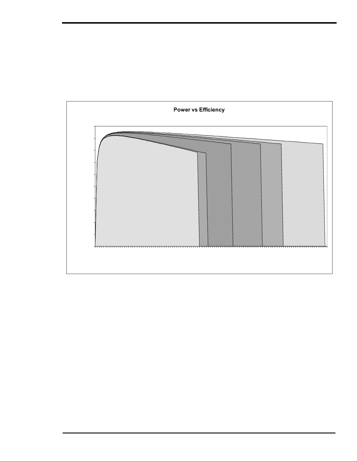
OPERATION
Power (VA)
POWER VS. EFFICIENCY
There are two primary losses that combine to create the eff iciency curve of the SW Series inver ter. The
first is the energy that is required to operate the inverter at full output voltage while deliver ing no current.
This is the no load or idle power. At low power levels, the idle power is the largest contributor to ef ficienc y
losses. At high power, the largest source of loss is a r esult of the res istance in the trans former and power
transistors. The power lost here is pr oportional to the s quar e of the output power. For ex ample, losses at
2000 watts will be four times higher than losses at 1000 watts. This graph represents a typical inverter’s
efficiency while operating resistive loads. Inductive loads such as motors ar e run less eff iciently due to the
impact of power factor losses.
100%
90%
80%
S
W
2
6
1
2
E
2500
2750
SW3024E / SW304 8E
3000
3250
SW4024 / SW4048
3500
3750
4000
SW4548E
4250
4500
4750
SW5548
5000
5250
5500
70%
60%
50%
Efficiency
40%
30%
20%
10%
0%
SW2512
0
250
500
750
1000
1250
1500
1750
2000
2250
Figure 19, Trace™ SW Series Efficiency Curves
The SW Series of f ers an ex trem ely good efficiency curve. The inver ter reac hes high ef f iciency at very low
AC load levels, which is important because the inver ter often spends the m ajority of the tim e at the lower
power range. The high efficiency is maintained over a wide power range. Only when operating at high
power levels at or above the continuous power levels does the efficiency begin to drop off. Since this
usually only occurs for short periods of time, the impact may be negligible.
If your application involves the inverter powering heavy loads for significant periods of time, selecting a
model with a higher continuous power rating and a higher DC input voltage would improve the operation of
the system. Since the low power efficiency of all the SW Series is extrem ely good, oversizing the inverter
does not reduce system performance.
2001 Xantrex Technology, Inc.
5916 - 195th Street N. E.
Arlington, WA 98223
Telephone: 360/435-8826
Fax: 360/435-2229
www.traceengineering.com
SW Series Inverter/Charger
Part No. 2031-5
Rev. C: February 2001
Page
59
Page 68

OPERATION
SW Series Inverter/Charger
INVERTER CAPACITY VS TEMPERATURE
The current protection circuit in the SW Series Inverter/Charger is tem perature compensated, therefore
the maximum s ized load that the inverter can run changes with temperature. As the temperature of the
power devices (FET’s) inc rease, the allowable current is reduc ed. W hen the available current is reduced,
the capacity of the inverter to run loads is reduced.
The graph below shows the effect tem perature has on the inverter’s c apacity to run loads, notice that the
inverter reduces its capacity at temperatur e above 25 °C. The temper ature derating graph assumes that
the inverter is at sea level and the airflow to the inverter is unrestricted.
Temperature Derating for SW Series Inverters
120
100
Percent
of
total
rated
power
capacity
80
60
40
20
0
25 32.5 40 47.5 55 62.5 70 77.5 85 92.5 100
Figure 20, Inverter Capacity vs. Temperature
Temperature °C
Page
60
2001 Xantrex Technology, Inc.
5916 - 195th Street N. E.
Arlington, WA 98223
Telephone: 360/435-8826
Fax: 360/435-2229
www.traceengineering.com
Part No. 2031-5
Rev. C: February 2001
Page 69

OPERATION
OPERATING MODES
The SW Series Inverter/Charger can be used in a wide variety and combination of operating modes:
• Inverter Mode - DC to AC inverter with sine wave output, high starting sur ge, power saving search
mode, low idle current, and very high efficiency DC to AC conversion.
• Charger Mode - Low AC current distortion, three stage, temper ature compensated, high amperage
battery charger.
• Inverter/Charger Mode - Automatic transfer f rom inverter to battery charging upon presence of utility
or generator AC power source.
• Generator Support Mode - Automatic “no glitch” switching from charger mode to inverter mode
allowing the inverter to assist the generator in starting and powering lar ge loads . Adjus table gener ator
support current and voltage thresholds.
• Automatic Generator Control Mode - Automatic generator starting, based on the battery voltage
reaching an adjustable voltage setting or the AC loads exceeding an amperage setting. Both start
conditions include adjustable time delays. Once started, the inverter operates in battery charger mode
until battery is charged to the float stage or until the AC load is reduced. The generator is then s hut of f
and the loads are powered from the battery through the inverter. Automatic generator exercising of the
generator and adjustable quiet time period to reduce generator operation m ay be programmed in the
setup menu.
• Utility Backup Mode - Phase synchronized fast AC transfer s witching for utility backup power supply
applications. Includes adjustable AC transfer voltage and line conditioning ability.
• Utility Interactive Mode - Excess power from charging sour ces or stor ed power from the battery can
be “sold” back into a utility grid. Also allows selling of the stored energy in the battery during a specific
time period.
• Energy Management Mode - Onboard clock to set inverter and charger operating tim e periods . This
mode can be used with “time of day” metering to shift energy consumption to off-peak periods.
• Peak Load Shaving M ode - Used to limit the draw of AC loads from a utility grid by powering it from
the batteries. The batteries are recharged when the AC loads ar e reduced. This can “level” the load
on a utility.
• Low Battery Transfer Mode - Automatic transfer of the AC loads from the batteries to the utility when
the system reaches an adjustable low battery voltage setting. Independent settings allow control of
when the AC loads return to battery once it is recharged.
Often, the inverter will be set-up to operate in several modes at the same or different times - such as
operating as an inverter/charger in utility back-up mode with automatic generator control mode and
generator support mode during extended utility outage periods.
ADDITIONAL FEATURES
Numerous additional features are provided to enhance and customize the inverter's operation for the
various operational modes:
• Automatic generator control system with adjustable quiet time period to reduce generator operation.
• Three-stage battery charging with fully adjustable charge settings and battery temperature sensing.
• AC and DC voltmeters and AC ammeters to allow monitoring of inverter, generator, and utility grid.
• On-board 24-hour clock for programming of generator quiet time and utility interactive modes.
• Adjustable sellback current level for utility interactive mode.
• Two separate AC inputs for utility and generator sources with utility priority.
• Three independently adjustable auxiliary signal relays for controlling charging sources, loads etc.
2001 Xantrex Technology, Inc.
5916 - 195th Street N. E.
Arlington, WA 98223
Telephone: 360/435-8826
Fax: 360/435-2229
www.traceengineering.com
SW Series Inverter/Charger
Part No. 2031-5
Rev. C: February 2001
Page
61
Page 70
OPERATION
SW Series Inverter/Charger
INVERTER MODE
BATTERY INVERTER AC LOADS
DC AC
IN BRIEF
The inverter makes a stepped approxim ation to a sine wave. T he num ber of s teps typically varies from 34
to 52 per cycle. Lower battery voltage and/or higher output power level increases the number of steps.
Higher battery voltage decreases the number of st eps. Distortion varies from 3% to 5%. The inverter is
able to control the AC output voltage, allowing the inverter to also sell power into a utility grid or ass ist
during the operation of heavy loads by operating in parallel with another AC power source such as a
engine powered generator.
SEARCH MODE CONTROL
An automatic search m ode circuit is available to minim ize the power draw of the inverter when no loads
are being operated. This reduces the power consum ption from 16 watts with no load to less than 1 watt
(when using the default settings). To do this , the output is reduced to pulses of a single AC cycle with an
adjustable delay between pulses. These pulses are used to detect the pr esence of a load. When a load is
detected, the inverter’s output goes to full 120 VAC output. The sensitivity of the detection circuit and the
spacing of the pulses are user adjustable using the Control Panel.
This feature can save a c onsiderable amount of power, particularly in smaller systems that do not have
loads operating all of the time. In larger systems, this feature may not result in as much savings. If
continuous operation of an AC load is required (such as when powering a microwave cloc k, VCR timer,
computer, or fax machine), then using the search mode is not recommended.
To enable the search mode: Select SRCH mode from the SET INVERTER menu item, accessible by
pushing the red ON/OFF MENU button. Pressing the red ON/OFF MENU button can also access the
SRCH mode. It is also located as the fir st menu item under the INVERTER MOD E (1) menu heading.
Pressing the red ON/OFF MENU button again will move the cursor one position to the right. T he SET
POINT buttons can also be used to move the cursor right or lef t. To disable the search m ode, select ON
from the SET INVERTER menu item.
Successful operation of the system utilizing the search mode requir es some initial tuning of the search
mode settings to matc h the loads connected in the system. If the loads change significantly, re-tuning of
the settings may be required. The benefit of the search mode c ircuit only is realized if the inverter is able
to enter the energy saving search mode for s ubstantial periods of the day. Occasional checking of the
yellow INVERT LED operation should be done to ensure that the search m ode is being used when all of
the loads are turned off (it should blink slowly if it is searching for a load).
SETTING SEARCH MODE WATTS
The search mode is user adjustable to allow fine-tuning of its operation. The settings are located under
the INVERTER SETUP (9) menu heading in the SETUP MENU. The following example explains the
operation:
Example: W ith the SEARCH WATTS setting at 32, a 50-watt load will bring the inverter to full output
voltage. However, a 30-watt load will leave the inverter in its energy saving search mode. If the sensitivity
is increased by lowering the setting to 16, a 20-watt load will bring the inverter out of the sear ch mode,
while a 5-watt load will not.
When in the sear ch mode, the yellow INVERT LED will blink slowly and the inverter will make a tick ing
sound. At full output voltage, the yellow INVERT LED will stay on and the inverter will make a steady
humming sound. W hen the inverter is used as an uninterruptible power supply, the search m ode should
be defeated.
Page
62
2001 Xantrex Technology, Inc.
5916 - 195th Street N. E.
Arlington, WA 98223
Telephone: 360/435-8826
Fax: 360/435-2229
www.traceengineering.com
Part No. 2031-5
Rev. C: February 2001
Page 71

OPERATION
Example A: If the SEARCH WATTS is set at 32 and a 30-watt incandescent light is turned on, the inverter
will detect the light. The initial load of the bulb is muc h greater than 32 watts when its filament is cold.
When the light gets bright, the f ilam ent heats up and the light bec om es a 30-watt load. Since this is below
the setting of 32, the inverter will not detect it and the light will turn off. This can cause cycling of the
inverter between on and off.
Example B: If the SEARCH WATTS setting is 32 and a 40-watt florescent light is turned on, the inverter
will not detect the light. The light presents a sm aller load than 32 watts until the gas in the f lorescent tube
ionizes and begins to glow. This problem is more common with the non-electronic type fluorescent bulbs.
Example C: There are some appliances that draw power even though they are turned off. TVs with instant
on circuits, microwave ovens with digital displays and VCRs with clock s are examples. These loads can
present a dilemma. If the SEARCH WATTS is set higher than the combination of these loads, then an
additional load must be used to bring the inverter out of the search mode before the applianc es can be
turned on. If the SEARCH WATTS is set lower than this combination of loads , then the inverter and the
loads will be left on. This will put an additional drain on the batteries (three such 15-watt loads would
amount to an additional 45 amp/hours per 24 hours in a 24 VDC system). One solution is to turn these
items off by using an extension cor d with a rocker switch, a switched outlet, or a circuit breaker for the
circuit. Unfortunately, this solution does not allow a clock to r etain its setting and may cause it to blink
constantly while operating.
SETTING SEARCH MODE SPACING
The SET SEARCH SPACING menu item is calibrated in cycles. To test for loads once each second,
adjust this setting to 59 (for 60 Hz models ) ; to test for loads about twice a second, adjus t the s etting to 30.
NOTE: The lower the search spacing value – the less time it tak es f or the inverter to bring up a load. T he
lower the setting), the greater the power consumption while in the sear ch mode, thus reducing power. The
factory default value (59) is acceptable for most applications. The range is from 4 to 255.
LOW BATTERY PROTECTION
When the actual batter y voltage reaches the LOW BATTERY CUT OUT menu item setting f or the LBCO
DELAY period, the inverter shuts off to prevent the battery from being over-discharged. If the inverter is
setup to automatically start a backup generator (Gen Auto Start Menu), then it will start once the battery
reaches the LBCO setting for the selected time (30 seconds, etc).
Any of the following three conditions will return the inverter to normal operation, after a LBCO condition:
1. Power is applied to the AC HOT IN 1 or AC HOT IN 2 input term inals, allowing the inverter to operate
as a battery charger.
2. The inverter is manually restarted by pushing the red ON/OFF button and selecting OFF and then
SRCH or ON.
3. Battery voltage rises above the SET LOW BATTERY CUT IN menu item setting.
While the inverter is shut off due to the battery reaching the LOW BATTERY CUT OUT settings, the red
ERROR LED will be illuminated. When the battery voltage increases to the LOW BATTERY CUT IN
setting, the inverter will automatically turn back on and the ERROR LED will turn off.
ADJUSTING THE LOW BATTERY PROTECTION
There are three settings used to prevent over -discharge of the battery. These settings ar e located under
the INVERTER SET UP (9) menu heading. See the SETUP MENU section for instructions on accessing
these settings.
The SET LOW BATTERY CUT OUT menu item deter m ines the voltage level that the battery must r each f or
it to be considered low. The inverter will continue to operate until the voltage has continuously remained
below this setting for the time period from the SET LBCO DELAY menu item. Onc e the inverter has shut of f,
the battery voltage must rise above the value from the SET LOW BATTERY CUT IN menu item.
The default LOW BATTERY CUT OUT setting may be lower than what is often recommended for m any
applications by battery manufacturers. It is set to allow max imum performance f rom the inverter, not to
maximize the life of the battery. If the system is properly designed, the inverter should not reach the LBCO
setting very often. If the system is expected to utilize the LBCO c ontrol on a regular basis, then inc reasing
this setting is recommended.
2001 Xantrex Technology, Inc.
5916 - 195th Street N. E.
Arlington, WA 98223
Telephone: 360/435-8826
Fax: 360/435-2229
www.traceengineering.com
SW Series Inverter/Charger
Part No. 2031-5
Rev. C: February 2001
Page
63
Page 72
OPERATION
SW Series Inverter/Charger
CHARGER MODE
AC SOURCE CHARGER BATTERY
AC DC
IN BRIEF
When AC power is available, the inver ter can operate as a very powerful battery charger with low current
distortion. Power is drawn over the full AC cycle. This improves the per f or mance with low AC input voltage
or with small generators.
The SW Series Inverter/Charger includes the ability to automatically “back-off” the battery charger to
prevent overloading a generator or tripping a circuit breaker when other AC loads are being operated
through the inverter. This improves system reliability and allows greater use of the power available. The
charger will also be turned off if the AC voltage drops to an adjustable lower limit VAC setting.
THREE STAGE CHARGING PROCESS
The charging cycle uses three stages. During the initial "Bulk Charge" stage, the inverter charges at
maximum rate allowed by the SET MAX CHARGE AMPS AC setting. This causes the battery voltage to
rise over time. After the batter y voltage nears the SET BULK VOLTS DC setting, the charger starts the
second or “Absorption” stage. During this phase, the charge rate is gradually reduced while the battery
voltage is held near the bulk voltage setting. This ensures that the battery is fully charged. The final "Float"
stage is initiated when the battery has been held near the SET BULK VOLTS DC setting for the
adjustable ABSORPTION TIME period setting. At this point, the battery voltage is allowed to fall to the
FLOAT VOLTS DC voltage setting, where it is maintained until another bulk charge c ycle is initiated. This
reduces gassing of the battery and keeps it fully charged. A new three-stage charge cycle is initiated after
an AC source is reapplied to the AC HOT input terminals, or daily if the BULK CHARGER TRIGGER
TIMER (15) is enabled and if AC power is available continuously.
Bulk Stage Absorption Stage Float Stage
Charging
Started
DC Voltage
AC Current
Increased Voltage Constant Voltage Reduced Voltage
Max Charge Amps
Setting
Constant Current Reduced Current Reduced Current
Time
Figure 21, Three-Stage Battery Charging
Bulk Volts Setting
Absorption Time
Float Volts Setting
If a generator was started autom atically by the
inverter to charge the battery, it will be shut off when
the charger reaches the float stage after the
bulk/absorption period. (GENERATOR must be in
AUTO mode)
Page
64
2001 Xantrex Technology, Inc.
5916 - 195th Street N. E.
Arlington, WA 98223
Telephone: 360/435-8826
Fax: 360/435-2229
www.traceengineering.com
Part No. 2031-5
Rev. C: February 2001
Page 73
BATTERY TEMPERATURE SENSOR (BTS)
A plug-in external Battery Temperature Sensor (BTS), which is provided,
automatically fine-tunes the charging process of the battery charger in
relation to temperature. When the temperature sensor is installed, the
charge voltage is adjusted either higher or lower than the BULK and
FLOAT setpoints based on temperature. The BATTERY TEMP COMP
VOLTS DC menu item under the METER S (4) menu heading shows this
adjusted charge voltage.
If the temperature s ensor is NOT installed and if the battery is subjec ted to
large temperature variations, a shorter battery life cycle may be expected.
Install the BTS on the side of the battery below the electrolyte level. It is best
if the sensor is placed between batteries and if the batteries are placed in
an insulated box to reduce the influence of the ambient temperature outs ide
the battery enclosure. Ventilate the battery box at the highest point to
prevent hydrogen accumulation.
OPERATION
Figure 22, BTS (Battery
Temperature Sensor)
The BTS provided may be extended beyond the standard 15 feet by an
additional 20 feet using standard telephone cables with RJ-11 plugs.
CHARGER ONLY OPERATION
When the CHG mode is selected, the inverter will operate only as a charger. Th is is usef ul f or unattended
operation where a power failure might allow the inverter to drain the batteries by powering an AC load
unnecessarily. To allow the Charger Only mode, FLT m us t be s elec ted f r om the SET GRID USAGE menu
item under the INVERTER SETUP (9) menu heading in the SETUP MENU (FLT is the factory default
setting).
This feature is comm only used in marine applications where the inverter operates a ref rigeration system
from the batteries. Norm ally, the engine’s alternators keep the batteries charged. W hen docked, a shore
cord is connected to the inverter to power the battery charger and run the refrigerator.
AC INPUT REQUIREMENTS
When an AC sour ce is applied to the AC input, the AC1 IN GOOD or AC2 IN GOOD LED indicator will
blink slowly once the AC voltage has been detected. If the AC source is acceptable, the inverter will
synchronize to it after a delay period has passed. Once synchronized, the inverter will close an internal
relay, connecting the AC source to the AC loads, indicated by the green AC IN GOOD LED (ON solid),
and begin charging the batteries, indicated by the orange BULK LED (ON solid).
The AC source, connected to the inverter ’s AC HOT IN 1 and AC HOT IN 2 term inals, is used to power
both the battery charger and the AC loads while the inverter is in the battery charger mode. T here are
several settings, listed below, that involve the AC INPUT. See the USER SETTING S WORKSHEET on
page 123 for factory default settings.
INPUT AC VOLTAGE
The AC HOT IN 1 and AC HOT IN 2 inputs share the same upper and lower limits for restricting
connection to an acceptable AC voltage operating window.
The AC input voltage window is typically set to the minimum / maximum range that the AC loads can
tolerate - the inverter itself can operate over an extremely wide voltage range. The upper and lower
settings are adjustable with the Control Panel and are located under the AC INPUTS (11) m enu heading
in the SETUP MENU.
2001 Xantrex Technology, Inc.
5916 - 195th Street N. E.
Arlington, WA 98223
Telephone: 360/435-8826
Fax: 360/435-2229
www.traceengineering.com
SW Series Inverter/Charger
Part No. 2031-5
Rev. C: February 2001
Page
65
Page 74

OPERATION
SW Series Inverter/Charger
AC CURRENT LEVEL
The maximum current draw into the AC HOT IN 1 terminal can be adjusted by the SET GRID (AC1)
AMPS AC menu item. The maxim um current draw into the AC H O T I N 2 term inal can be adjusted by the
SET GEN (AC2) AMPS AC menu item. These adj ustments are used to “back off ” the battery charger’s
AC current draw while other AC loads are being powered through the inverter. This prevents the
overloading of the AC source and prevents nuisance tripping of the AC source circuit breakers.
FREQUENCY
AC HOT IN 1 is the Utility Power connection point. The frequency tolerance is 53 to 67 Hz for 60 Hz
models (44 to 56 for 50 Hz m odels). The typical transfer delay is approximately 30 s econds once the AC
HOT IN 1 terminals are energized. W hen the SELL m ode is enabled from the SET GRID USAGE menu
item, the transfer delay period is typically 90 seconds and the frequency tolerance is restricted to 58 to 62
Hz for 60 Hz models (48 to 52 Hz for 50 Hz models).
AC HOT IN 2 is used as a fuel-powered generator c onnection point. There is a default 60-second delay
before transfer occurs. This gives the generator time to stabilize before being loaded. Frequency tolerance
is 53 to 67 Hz for 60 Hz models (44 to 56 for 50 Hz models). The f uel-powered generator mus t be stable
for the inverter to synchronize and connect.
DELAY PERIOD
The delay period, approximately 30 seconds, occurs af ter the AC sour c e has been applied to the AC H OT
IN 1 terminal. If SELL mode is enabled (from the SET GRID USAGE menu item under the INVERTER
SETUP (9) menu heading) and a power outage occurs, reconnection back to the utility power will be
delayed for a period of at least 90 seconds. This delay allows the utility distribution system to stabilize
before the inverter resumes selling power back to the utility. It is not adjustable.
The delay period for the AC H OT IN 2 ter minal is adj ustable through the SET GEN WARMUP SECONDS
menu item under the GEN STARTING DETAILS (13) menu heading. This allows the generator to reac h a
stable operating condition before being loaded. The default generator warm-up period is 60 seconds.
Once warmed up, the inverter synchronizes to the generator. If the AC source is not stable, the inverter
may not be able to synchronize and will not connect. If the generator runs for 5 minutes without the
inverter being able to connect, then the generator will be shut off and the ERROR LED indicator will be
illuminated. A GENERATOR SYNC, YES error condition will be displayed in the ERROR CAUSES (5)
menu heading on the Control Panel.
RECOMMENDED BATTERY CHARGER SETTINGS
The settings for the battery charger primarily depend upon the battery chemistry and construction. Other
factors such as usage, age and battery bank size need to be considered as well. T he battery charger
settings will automatically adjust if the temperature c ompensation sensor is installed. If it is not installed,
the settings should be adjusted manually to allow for the typical battery temperature. This may require
seasonal readjustment for optimum performance.
The default settings are typical values for liquid, lead acid battery applications. They will work satisfac torily
for many systems.
CAUTION: To prevent battery damage and achieve maximum performance, adjust the battery
charger settings to the manufacturer’s recommendations. NiCad (or alkaline) battery users must
also adjust the SET TEMP CO MP menu item setting. The battery charger settings are located
under the BATTERY CHARGER (10) menu heading in the SETUP MENU.
The SET MAX CHARGE AMPS AC menu item will need to be reduced if you are using a small battery
bank. High charge rates can caus e a small battery to overheat. This may cause dam age and is not an
efficient way to recharge the battery. With the Control Panel, adjust the charger for a maximum rate that is
less than 1/5 of the battery capacity for efficient recharging. For ex ample, if the battery is rated at 500
amp-hours, set the m aximum charge rate for 100 amps DC. Since the setting is adjus ted in amps AC
drawn by the battery charger, divide the DC charge rate by 8 for 12 volt systems, 4 for 24 volt systems and
2 for 48 volt systems (these f actors are for 120 VAC systems and include the power lost in the battery
charger). If the exam ple battery bank of 500 amp hours was a 24 volt system, the m aximum AC amps
setting should be around 25 amps AC (500 x 1/5 = 100 amps DC, 100 / 4 = 25 amps AC
.)
Page
66
2001 Xantrex Technology, Inc.
5916 - 195th Street N. E.
Arlington, WA 98223
Telephone: 360/435-8826
Fax: 360/435-2229
www.traceengineering.com
Part No. 2031-5
Rev. C: February 2001
Page 75

OPERATION
Once the battery voltage nears the BULK VOLTS DC setting, the voltage will be held at this level while the
current into the battery tapers off. The tim e allowed for this tapering period is called the ABSORPTION
TIME period. This setting is very important for systems which us e generator s sinc e it deter mines how long
a generator will run and when the generator shuts off. Using a gener ator to “trickle” charge a battery is not
efficient and should be avoided. Some users may want to decrease the ABSORPTION TIME to keep
generator-running time to a minimum. T his may result in the batteries not being fully charged. The higher
the BULK VOLTS DC setting and the longer the ABSORPTION TIME period, the more f ully charged the
battery would be when the charger is shut off. Of ten, the generator is used only to “BULK CHARGE” the
battery and the solar array is allowed to trickle charge the battery to a full charge condition.
The following chart provides a guideline in setting the battery charger s ettings for several differ ent types of
batteries. The battery manufacturer is the best source of information and should be consulted if your
battery type is not shown. Since the settings also depend on the system design, other factors may apply.
Table 4, Charging Setpoints For Common Battery Types
TYPICAL BULK AND FLOAT SETPOINTS FOR COMMON BATTERY TYPES
Battery Type Bulk Volts Float Volts Equalizing Charge Process
Sealed Gel
Lead Acid battery
A.G.M.
Lead Acid battery
Maintenance-Free RV/Marine
Lead Calcium Battery
Deep-Cycle, Liquid Electrol yte
Lead Antimony Battery
NiCad or NiFe Alkaline Batte ry*
(using 10 cells in series )
14.1 VDC BULK 13.6 VDC FLOAT Not Recommended - Consult manufacturer
14.4 VDC BULK 13.4 VDC FLOAT Charge to 15.5 VDC or as per manufacturer
14.4 VDC BULK 13.4 VDC FLOAT Not Recommended - Consult manufacturer
14.6 VDC BULK 13.4 VDC FLOAT Charge to 15.5 VDC or as per manufacturer
16.0 VDC BULK 14.5 VDC FLOAT Consult manufacturer
Note: Values shown are f o r 12 vol t syste ms. For 2 4 vo l t syst em s mul ti p l y the sett i ng s shown by 2.
For 48 volt systems multiply the settings shown by 4. These settings are guidelines, refer to your
battery manufacturer for specific settings.
EQUALIZING BATTERIES (UNSEALED OR VENTED BATTERIES ONLY)
In many of the inverter/charger applications, batteries are subjected to less than ideal operating
conditions. This can result in significant differences in the state-of-charge level between the individual
battery cells. Furthermore, the low charge rates and ex tended periods at par tial char ge levels c an res ult in
both stratified battery electrolyte and inactive areas of battery plate material. If the condition is allowed to
remain for extended periods of time, the battery can “sulfate” and become unusable.
To correct this condition, m any manufacturers recomm end a periodic “equalization” charge to mix up the
electrolyte, re-activate unused battery plate material, and bring up all of the individual cells to a f ull s tate of
charge. This requires that the batter y be given a controlled “overcharge” by increasing the charge voltage
for a limited period of time. The voltage and time required are both dependent upon the amount of
correction required. The mor e frequently the batteries are equalized, the lower the equalize voltage and
shorter the time period.
Equalizing a battery is only recommended on unsealed or vented batteries. T he process will cause the
electrolyte to gas and will release hydrogen and oxygen in the process. The chance of explos ion due to
the accumulation of these gasses is therefor e a r ealistic hazard. T he batteries must be provided with good
ventilation with no ignition sources present. Some us ers have f ound that the batter y cell caps are subject
to clogging during an equalization charge and therefore remove them during this process. Since the
batteries may rapidly bubble while being charged, it is advised that the battery be refilled only after the
equalization process is finished (if the battery electrolyte level is low, add enough to cover the plates
before charging).
2001 Xantrex Technology, Inc.
5916 - 195th Street N. E.
Arlington, WA 98223
Telephone: 360/435-8826
Fax: 360/435-2229
www.traceengineering.com
SW Series Inverter/Charger
Part No. 2031-5
Rev. C: February 2001
Page
67
Page 76

OPERATION
SW Series Inverter/Charger
The battery manufacturer or supplier s hould be consulted before equalizing to provide the recom mended
process and settings. During the equalization process, check the temperature of eac h battery every hour
by momentarily feeling the battery case. If the batteries are excess ively warm (too hot to keep your hand
on), terminate the charging immediately. Let the batteries cool before checking the need for further
equalization charging.
A manual or automatically controlled equalization charge process is available in the SW Series
Inverter/Charger. This equalization process can be powered by any AC source. The SET EQUALIZE
TIME H: M menu item under the BATTERY CHARGING (10) menu heading sets the amount of time that
the battery voltage must exceed the SET BULK VOLTS DC setting before the equalization process is
completed. This tim er is an acc umulating type and does not reset if the voltage m omentarily drops below
the bulk voltage setting. During the equalization process, the voltage is limited to the level of the SET
EQUALIZE VOLTS DC menu item under the BATTERY CHARGING (10) menu heading.
To start the equalization process (either manually or automatically):
Select EQ from the SET GENERATOR menu item, by pressing the green GEN MENU button on the
Control Panel. During the equalization process, the BULK LED will flash slowly to indicate that the EQ
position has been selected from the SET GENERATOR menu item.
To manually equalize the batteries, AC power must be available at the AC HOT IN 1 (utility power) or AC
HOT IN 2 (generator) terminals. If utility power is not available, the generator m ust be manually started.
The inverter uses this power to start the battery charger and begin the equalization process. Equalization
will continue to run for the amount of time programmed. When the equalization process finishes, the
FLOAT LED will come on (as long as utility or generator power is still available).
NOTE: If the generator was manually started to equalize the batteries, it must be manually shut off
once equalization has completed. Return the cursor to the OFF position in the SET GENERATOR
menu item (accessible by pressing the green GEN MENU button on the Control Panel).
If the automatic generator control system is selected, the inverter will complete an equalization charge
process during the next - automatically started - generator run period.
Page
68
2001 Xantrex Technology, Inc.
5916 - 195th Street N. E.
Arlington, WA 98223
Telephone: 360/435-8826
Fax: 360/435-2229
www.traceengineering.com
Part No. 2031-5
Rev. C: February 2001
Page 77

INVERTER/CHARGER MODE
UTILITY GRID
AC
AC
INVERTER/
CHARGER
AC
OPERATION
AC LOADS
GENERATOR
DC
BATTERY
IN BRIEF
The SW Series Inverter/Charger is capable of autom atically transferring AC loads from the inver ter to a
utility grid or generator. Once transferred, the inverter can recharge the battery. The inverter/charger can
transfer upon the availability of AC power (FLT mode), either at a spec ific tim e each day (using the GRID
USAGE TIMER (18) menu heading), or upon a low battery condition (LBX mode).
TRANSFERRING UPON AVAILABILITY OF AC POWER
When AC power is supplied to the AC HOT IN 1 or AC HOT IN 2 input, the inverter automatically transfers
from inverter mode to battery charger mode. Before transferring, the inverter verifies that both the AC
input voltage and frequency are within tolerance. It then synchronizes waveforms and c onnects to the
inverter’s AC output without interruption of power.
The FLT mode is the default mode ( see the GRID USAGE menu item under the INVERTER SET UP (9)
menu heading) and may be used with AC power supplied to either the AC HOT IN 1 or AC HOT IN 2
input. This is the proper m ode for most utility connected applications or for use with a back-up generator
that is being manually or automatically started.
The SLT m ode is used only with AC power supplied to the AC HOT I N 1 input. The SLT m ode is selected
from the GRID USAGE menu item under the INVERTER SETUP (9) menu heading. In this mode, the only
operational difference is that the battery charger will only be engaged for a single period of tim e each day,
set by the BULK CHARGE TRIGGER TIMER (15) menu heading setting. This reduces the power
consumption of the inverter over the period of a day. It is also us ed in applications where the slight noise
of the inverter might be undesirable, such as at night. AC power continues to be passed through the
inverter’s transfer relay while the charger is not engaged. If the AC source fails, the inverter will turn on
automatically and power the connected AC loads. When utility power returns, the AC loads will be
reconnected to the utility and the battery charger will complete a bulk charge cycle. Once this has been
completed the battery charger will turn off, but the loads will remain connected to the utility.
TRANSFERRING BA SED ON BATTERY VOLTAGE
The LBX mode is used only with AC power supplied to the AC HOT IN 1 input. The LBX mode is selec ted
from the GRID USAGE menu item under the INVERTER SETUP (9) menu heading. In this mode, the
decision to transfer to and from charger m ode will be based upon the battery voltage. W ith LBX enabled,
the SET LOW BATTERY CUT IN VDC setting and the SET LOW BATTERY TRANSFER VDC setting
determine the DC transfer voltages. W hen the battery voltage reaches the LOW BATTERY TRANSFER
VDC setting for more then 20 seconds, the AC loads are transferred from the inverter to the utility. If the
battery voltage reaches the LOW BATTERY CUT IN VDC setting, the AC loads are transferred from the
utility to the inverter. The low battery transfer system includes a 20 second delay so that large loads are
less likely to cause a transfer to the utility grid during motor startup, etc.
2001 Xantrex Technology, Inc.
5916 - 195th Street N. E.
Arlington, WA 98223
Telephone: 360/435-8826
Fax: 360/435-2229
www.traceengineering.com
SW Series Inverter/Charger
Part No. 2031-5
Rev. C: February 2001
Page
69
Page 78

OPERATION
SW Series Inverter/Charger
While connected to the utility, the battery charger will be engaged. Some applications may want to allow
the alternate power source (solar, wind or hydro) to recharge the battery instead of allowing the utility to
provide the power. The only option is to program the SET MAX CHARGE AMPS AC menu item under the
BATTERY CHARGING (10) menu heading to the minimum value, 1 am p AC, and set the BULK VOLTS
and FLOAT VOLTS settings, also under the BATTERY CHARGING (10) menu heading, to a low value.
TRANSFER TIME
Normally there is no transfer tim e from the inverter to utility power or generator. The inverter operates in
parallel with the AC source at all times - even when battery charging. This allows the trans f er f r om inverter
to the utility grid or generator to be interruption-free and virtually unnoticeable.
However, in SELL mode, when the utility grid fails, the inverter will reach the overcurrent protection
system setting (since it is will try to power everything that is connected to the grid). The inverter will
momentarily shut off while it opens the inter nal AC input r elay. Once the relay has opened, the invert er will
begin to operate within a single cycle. This results in a 20 millisecond transfer period. Most AC loads,
including computers, will not be affected during the transfer.
Page
70
2001 Xantrex Technology, Inc.
5916 - 195th Street N. E.
Arlington, WA 98223
Telephone: 360/435-8826
Fax: 360/435-2229
www.traceengineering.com
Part No. 2031-5
Rev. C: February 2001
Page 79

GENERATOR SUPPORT MODE
OPERATION
GENERATOR AC LOADS
AC AC
INVERTER/
CHARGER
DC
BATTERY
IN BRIEF
The factory default settings are intended to operate the inverter as an inverter/charger connected to a
generator. When the generator is off, the inverter will power the AC loads from the battery. Once the
generator is started, the AC loads will be transferred to the generator and the inverter will become a
battery charger and store the unused power in the batteries f or later use. The inver ter will automatically
limit the draw of the battery charger to prevent overloading the generator. When the generator is turned off
it will be disconnected and the inverter will instantly take over and power the AC loads from the batteries.
Generator support does not require that the automatic generator control system be used.
To operate in this mode the system must be set-up as follows:
• Connect the generator AC output to the inverter’s AC HOT IN 2 and NEUTRAL IN 2 terminals.
• Connect the AC loads to the inverter’s AC HOT OUT and NEUTRAL OUT terminals.
• Adjust the battery charger parameters to m atch the requirements of the batteries connected (if the
factory defaults listed in the technical section are not satisfactory).
• Adjust the SET GEN (AC2) AMPS AC menu item located in the AC INPUTS (11) menu heading, to
the continuous output ability of the generator. This allows the generator s upport feature to function
correctly, preventing the generator from being overloaded. The gener ator’s output should be de-rated
for altitude and if propane or natural gas is the power source. It is best to err or on the low side for this
setting, or to experiment with higher settings after the system has been operational.
• Adjust the SET INPUT LOWER LIMIT VAC located in the AC INPUTS (11) menu heading, to the
lowest AC voltage that the AC loads can tolerate. If the gener ator is pulled down to this level while
powering a load, the inverter will back-off its battery charging or even oper ate in parallel to reduc e the
load on the generator. Keep in mind that when the inverter supports the generator it uses energy from
the batteries to power the AC loads. Therefore, when generator support occurs, the batteries can be
discharging instead of recharging even though the generator is running.
• Adjust the SET INPUT UPPER LIMIT VAC located in the AC INPUT (11) menu heading, to the
highest voltage that the generator will be allowed to operate without being considered out of tolerance.
At this voltage the inverter will disconnect to protect the AC loads. W hen the voltage returns to the
operating window, the inverter will require a minimum of 20 seconds to re-synchronize and connect
the generator to the loads.
2001 Xantrex Technology, Inc.
5916 - 195th Street N. E.
Arlington, WA 98223
Telephone: 360/435-8826
Fax: 360/435-2229
www.traceengineering.com
SW Series Inverter/Charger
Part No. 2031-5
Rev. C: February 2001
Page
71
Page 80

OPERATION
SW Series Inverter/Charger
GENERATOR SUPPORT/OVERLOAD PROTECTION
This battery charger is quite powerful and, without limits, could overload a generator. When the generator
is running, it has to power both the battery charger and any connected AC loads. If the AC load current,
combined with the charge current, exc eeds the SET GEN (AC2) AMPS AC setting, the charge rate will
automatically be reduced to avoid overloading the generator or tripping its circuit breaker.
If the amount of current demanded by the AC load is greater than the GEN (AC2) AMPS AC setting, the
inverter is capable of supplementing the generator’s power. The inverter attempts to hold the current
drawn from the generator at the setting of the GEN (AC2) AMPS AC. This allows the generator to start
larger loads than it could normally and reduces the load on the generator during motor start-ups.
Generator support is also available if AC voltage falls to the SET INPUT LOWER LIMIT VAC. In this case,
the inverter will assist the generator as long as there is power flowing from the generator to the load. This
is typically used when a large AC load is being operated and the generator’s AC output voltage drops.
For example, if you have a 20 amp generator and the GEN SIZE AMPS AC setting is at 15 amps, the
inverter will start providing additional power from the batteries whenever the load reaches 15 amps or
higher (even though it may not be required). When setting the GEN SIZE AMPS AC value, allow for
headroom but do not set the value too low.
While the inverter is suppor ting the generator, the BULK or FLOAT LED Indicator will remain on even
though the inverter may not be battery charging. The INVERTER/CHARGER AMPS AC meter will indicate
the support process by displaying “negative” current flowing from the inverter to the loads. The INPUT
AMPS AC will also drop during this process while the LOAD AMPS AC remains the same.
120 VAC VS. 120/240 VA C GENERATORS
In the US, generators are available with either 120/240 VAC “split phase” or 120 VAC only output. Some
generators can be rewired in the field, or have a switch, for changing from one output to the other. If a
system uses only one inverter, having the generator put out all of its power at 120 VAC is advantageous. If
two inverters are used, having the generator wired for 120/240 VAC output is better.
If you are using one inverter and can not rewire your generator for 120 VAC, or have a com bination of 120
and 240 VAC loads which need to be operated, you may need to include a balancing transformer to allow
full use of the generator output at 120 VAC. This allows the battery charger to use power from both
“halves” of the generator, instead of only half of it. Xantrex of f er s a balancing tr ans f ormer (Part Number T-
240) for this purpose. See OTHER PRODUCTS section on page 129 or contact your inverter supplier for
more information.
If your generator can be wired for 120 VAC output and you are using only one inverter, 240 VAC loads can
be operated from the system by using a transform er in a step-up conf iguration. This is c omm on for deep
well submersible well pumps. If the step-up is done on the pump side of the pressur e switch or manual
switch for the pump (run 120 VAC through the switch then step it up to 240 VAC), the transf orm er will not
interfere with using the search mode or increase idle current draw by the inverter when the pump is off.
When two inverters are operating in a “series stacked” configuration (120/240 VAC); each inverter
operates as a separate inverter. One inverter can be battery charging with the excess power fr om one half
of the generator, while the other inverter is supporting the generator by operating in parallel to support a
heavy 120 VAC load on that half of the system. This allows greater utilization of limited system capacity
and is very useful when starting large 120 VAC loads such as water pumps or compressors.
Two 120 VAC/60 HZ inverters can be used to provide 240 VAC. T his provides both 120 and 240 VAC
since a center “neutral” is provided between the two inverters. If a 240 VAC only AC source is c onnected
to the AC input terminals of the inverter without this center neutral, unacceptable operation will r esult. To
allow connection of a 240 VAC only source, a small (500 VA) autotransform er m ust be connected acros s
the 240 VAC input and to the AC neutral terminals of the inverters. This will allow the inverter to oper ate
properly. No transformer is requir ed on the AC output side - the 240 VAC can be taken directly from the
two AC hot output terminals (one from each inverter).
Page
72
2001 Xantrex Technology, Inc.
5916 - 195th Street N. E.
Arlington, WA 98223
Telephone: 360/435-8826
Fax: 360/435-2229
www.traceengineering.com
Part No. 2031-5
Rev. C: February 2001
Page 81

AUTOMATIC GENERATOR CONTROL MODE
OPERATION
GENERATOR AC LOADS
AC
CONTROL
INVERTER/
CHARGER
AC
DC
BATTERY
IN BRIEF
Automatic start/stop contr ol of a back -up generator can be us ed with any of the other oper ating m odes. If
used with an application that includes utility power, the generator will be started only if the utility power is
not available. It is not possible to use both generator and utility power at the same time. If the generator is
manually started while the inverter is connected to utility power, the inverter will ignore the generator and
not connect to it. W ith utility power connected to the AC HOT IN 1 terminals, the autom atic gener ator start
and stop control is disabled.
Extensive control of automatic generator operation is available through the items under the menu
headings GEN AUTO START SETUP (12), GEN STARTING DETAILS (13) and GENERATOR TIMER
(7). The generator can be set to start based on four diff erent low battery voltage levels with diff erent delay
times for each. A quiet tim e period can be set that restricts the generator from starting during defined
hours of the day. The generator will be started during the quiet time period only if the battery voltage
reaches the setting of the SET LOW BATTERY CUT OUT VDC MENU ITEM for a continuous 30- second
period of time.
To operate in this mode the system must be set-up as follows:
• Connect the generator AC output to the inverter’s AC HOT IN 2 and NEUTRAL IN 2 terminals.
• Connect the AC loads to the inverter’s AC HOT OUT and NEUTRAL OUT terminals.
• Select AUTO f rom the SET GENERATOR menu item, accessed by pressing the green GEN MENU
button. The AUTO mode is dis abled if the CHG mode under INVERTER MODE (1) menu heading is
selected.
• Adjust the battery charger parameters to m atch the requirements of the batteries connected (if the
factory defaults listed in the technical section are not satisfactory).
• Adjust the SET GEN (AC2) AMPS AC menu item, located in the AC INPUTS (11) menu heading, to
the continuous output ability of the generator. This allows the generator s upport feature to function
correctly, preventing the generator from being over loaded. The generator’s output should be derated
for altitude and if propane or natural gas is powering it. It is best to error on the low side for this
setting, or to experiment with higher settings after the system has been operational.
• Adjust the SET INPUT LOWER LIMIT VAC menu item, located in the AC INPUTS (11) menu
heading, to the lowest AC voltage that the AC loads can tolerate. If the generator is pulled down to this
level while powering a load, the inverter will back-off its battery charging or even operate in parallel to
reduce the load on the generator. Keep in mind that when the inverter supports the generator it uses
energy from the batteries to power the AC loads. Therefore, when generator support occurs, the
batteries can be discharging instead of recharging even though the generator is running.
• Adjust the SET INPUT UPPER LIMIT VAC menu item , located in the AC INPUT (11) menu heading,
to the highest voltage that the generator will be allowed to operate without being considered out of
tolerance. At this voltage the inverter will disconnect to protect the AC loads. When the voltage returns
to the operating window, the inverter will require a minimum of 20 seconds to re-synchronize and
connect the generator to the loads.
2001 Xantrex Technology, Inc.
5916 - 195th Street N. E.
Arlington, WA 98223
Telephone: 360/435-8826
Fax: 360/435-2229
www.traceengineering.com
SW Series Inverter/Charger
Part No. 2031-5
Rev. C: February 2001
Page
73
Page 82

OPERATION
SW Series Inverter/Charger
GEN CONTROL RELAYS
CAUTION: All circuits connecting the auto generator control system M UST be protected
with fuses rated at 5 amps o r less. T he warranty does not cov er damage to these relays.
Fuses should be located as close as possible to the point of connection to the lar ger conductors
providing power from the battery. A fuse mus t be used, even if the c ircuit is providing only a “dry
contact” or “ground” connection - it will prevent dam age if the connection is miswired or if the
cable connecting the inverter to the generator is damaged.
The generator control relays are not intended to directly control the starter motor or operate the ignition
system - rather they are used to send a signal to operate the coil of another higher amperage device
which does the actual switching of power. For location and wiring inform ation on the GEN CONTROL
RELAYS, see AUXILIARY AND GENERATOR CONTROL RELAY on page 14.
The SW Series Inverter/Charger provides two relays, labeled RY7 and RY8, to allow starting of many
types of generators. Two LED indicators provide status indications whether RY7 or RY8 have been
energized.
The relay labeled RY7 is used to provide either a STOP signal or a RUN signal. It can also be used to
provide a GLOW signal on diesel generators with glow-plugs. The relay labeled RY8 is used to provide a
crank signal for the starter of the generator engine. It is not used on two-wire type (auto cranking)
generators. The COM (comm on) term inals of the relays are separated and both the N.O. (nor mally open)
and N.C. (normally closed) contacts of the relays are provided.
It is much easier to m ake the connections to the generator if a remote control terminal or connector is
available on the generator. This sometimes requires that the generator optional remote control be
purchased. This also allows exam ination of how the generator rem ote control works - which is what the
inverter’s generator control system in the inverter must duplicate.
Connection of the GEN CONTROL RELAYS to the generator remote control also eliminates the need to
modify the generator and violate the warranty of the generator.
You should also add a switch to allow disabling of the automatic generator contr ol s ystem at the gener ator
to allow local control of the generator, preventing starting while servicing, etc. Many generators include this
switch with the optional remote control.
GENERATOR STARTING SCENARIOS
The generator can be set to start based on the four following scenarios:
AUTOMATICALLY
(1) AC Current: The generator starts whenever the current travelling through the inverter to the AC
loads remains above the LOAD START AMPS AC setting for the selected LOAD START DELAY
MIN period. T he current can be m onitored by the LOAD AMPS AC menu item under the METERS
menu. The generator will start, unles s the tim er is in the “quiet tim e” period, at which time it will only
start if the READ LBCO 30 SEC START VDC setting is reached. W henever the generator starts
automatically, based on load amps, it will shut off once the load current drops below the LOAD
START AMPS value for the selected LOAD STOP DELAY MIN period.
(2) Battery Voltage: The generator starts whenever the battery voltage reaches one of the four
adjustable low battery voltage levels for the selected delay periods (24 hours, 2 hours, 15 minutes, or
30 seconds). The low battery voltage levels are set under the GEN AUTO START SETUP. Actual
battery voltage can be monitored from the BATTERY ACTUAL VOLTS DC menu item under the
METERS menu. The generator will start, unless the timer is in the “quiet time” period, at which tim e it
will only start if the SET LOW BATTERY CUTOUT VDC or READ LBCO 30 SEC START VDC
setting is reached. Whenever the generator starts automatically, based on low battery voltage it will
shut off once the BULK and ABSORPTION stages of the battery charging have completed, thus
fully recharging the batteries.
Page
74
2001 Xantrex Technology, Inc.
5916 - 195th Street N. E.
Arlington, WA 98223
Telephone: 360/435-8826
Fax: 360/435-2229
www.traceengineering.com
Part No. 2031-5
Rev. C: February 2001
Page 83

OPERATION
(3) Time (Exercise Period Days): The generator is automatically started at a pre-selected time
whenever it exceeds a set number of days without running. Once the start comm and is initiated,
the generator starts and runs for 15 minutes to ensure that it remains f ully operational and that the
generator’s starting battery is maintained at an optimal state of charge. To set generator start
time, go to END QUIET TIME under the GENERATOR TIMER menu. To set the number of days
between exercise periods, go to SET EXERCISE PERIOD DAYS under the GEN AUTO START
SETUP menu. If the value is s et to 10, the generator will start every tenth day of c ontinuous nonoperation. To disable this feature, set the value to zero.
MANUALLY
(4) M anual Start – T he generator can be m anually started by selecting ON from SET GENERATOR
directory under the GENERATOR MODE menu. In manual mode, the generator MUST be
manually switched OFF by selecting OFF from the SET GENERATOR menu item.
GENERATOR STARTING AND STOPPING CONFIGURATIONS
Two different generator start routines are available to allow use with a wider variety of generator types.
The sequence of closing and opening of the RY7 relay changes depending upon what position the
underlining cursor is in fr om the SET RY7 FUNCTION menu item under the GEN STARTING DETAILS
(13) menu item. The choices are GLOWSTOP or RUN.
When RUN is selected as the func tion of the RY7 relay, the RY7 COM and RY7 N.O. contacts remain
closed while the generator is running. This is usually wired to the ignition system of the generator engine
and/or a fuel solenoid valve. The norm ally closed contacts of this relay are also available on the term inal
block, mark ed RY7 N.C. The normally closed contact is open ( not connected to the common terminal)
while the generator is running. W hen the generator is off , the RY7 N.C. terminal is c onnected to the RY7
COM terminal. This configuration is us eful for starting many HONDA brand gener ators as well as som e
others. This should also be used to select when the RY7 COM and RY7 N.O. contacts are used to control
a two wire (auto crank) type generator.
When GLOWSTOP is selected as the function of the RY7 relay, the RY7 COM and RY7 N.O. contacts
remain open while the generator is running. T he contac ts clos e only when it is time for the gener ator to be
stopped. This is useful for generators that require a stop signal to shut down the generator. The
GLOWSTOP configuration is useful for starting ONAN brand generators.
The GLOWSTOP setting can also be used for diesel generators. The RY7 COM and RY7 N.O. contacts
will be closed during the PRE CRANK SECONDS period. This relay can be used to provide both the
GLOW and STOP signals. When this is done the gener ator will be given both GLOW and STOP signals
before cranking and when stopping. This is done on many diesel generators by their own starting systems.
You should also check that the control system also powers the glow plugs during the cr anking signal - the
generator manufacturer or dealer can provide more information.
The terminals RY8 COM and RY8 N.O. provide contacts that remain closed only during the gener atorcranking period. This is usually wired to the starter solenoid (relay) of the generator engine. This relay
closes after an initial PRE CRANK delay period (the default MAX CRANKING SECONDS period is 10
seconds). Relay RY8 will open after a half-second delay, once the inverter senses an AC voltage above
80 VAC on the AC HOT IN 2 terminals. If the voltage r emains for the POST CRANK period, relay RY8 will
remain open. If the generator doesn’t start, it will close again after a POST CRANK delay period. The
inverter will attempt to start the generator up to 5 times (the number of times the inverter tries to start the
generator is fixed at 5 attempts). If the required voltage level is not reached, relay RY7 opens (in RUN
mode) to “kill” the gener ator before a restar t is attempted. T his reduces the chanc e that the starter m otor
will be engaged on a spinning generator engine. This protection is inherent in the GLOWSTOP mode.
The generator will be stopped when the battery charger has kept the tem perature compensated battery
voltage near the BULK VOLTS DC setting for the ABSORPTION TIME period.
When it is tim e to stop the generator, r elay RY7 will open or close (depending on which RY7 FUNCTION
is selected), stopping the generator. This will occur af ter a 40 second cool down period. If the generator
does not stop, the inverter will continue to charge the battery at the FLOAT VOLTS DC.
The transfer f rom generator to inverter will be less notic eable if you manually turn off the generator f rom
the inverter’s Control Panel instead of from the generator’s off switch. This allows the inverter to first
disconnect the generator before it is turned off, reducing problems with voltage sags during the transition.
2001 Xantrex Technology, Inc.
5916 - 195th Street N. E.
Arlington, WA 98223
Telephone: 360/435-8826
Fax: 360/435-2229
www.traceengineering.com
SW Series Inverter/Charger
Part No. 2031-5
Rev. C: February 2001
Page
75
Page 84
OPERATION
SW Series Inverter/Charger
GENERATOR AUTO START REQUIREMENTS AND TYPES
In order for the generator to be automatically started, it must include electric star t and an automatic choke.
An automatic primer system m ay also be required on natural gas and propane powered generators. The
generator should also include remote s tart ability with accessible remote start term inals or a connector.
Protective systems for low oil pressure, over temperature, starter lockout and over crank control are
valuable features that will prevent generator damage and increase system reliability. “Two wire” start
generator are recommended highly because of the greater simp licity for automatic starting and because
they are intended for remote/automatic/unattended operation.
Generators used can be fueled by gasoline, propane or diesel f uel. Propane is often the best choice for
residential applications due to the ease of fuel storage and delivery, cost, safety, and ease of starting.
Since propane is required for the cooking stove, water heater and space heating as well, most r esidential
applications will already have a tank and propane service. Gasoline is als o com m on, but c an be diff icult to
transport and store on site safely. Most sm all generators do not hold much fuel in their built-in tanks refitting the generator to use mar ine outboard motor type fuel tanks is often a good solution for limited fuel
capacity. This eliminates the need to pour fuel into the tank of a hot generator - which can be very
dangerous. Diesel is a much safer fuel to use and store. Diesel generators can operate with very little
maintenance and have very long lives. The only problems with diesel are the higher initial cost, dif ficulty
with starting in cold weather and possible need for the additional control of the glow plugs before starting.
Generators can be either air or water-cooled. W ater-cooled units are usually more quiet but can r equire
more maintenance. Low speed (~1800 / 1500 rpm) generators are pref erred by many system designers
as they often provide longer life due to less mechanical wear and tear.
TWO WIRE START GENERATORS
Generator starting requirem ents c an be divided into two categories – t w o - w ire st art types and three-wire
start types. The two-wire start type generator is more simple and the eas ies t to automate. To star t, simply
connect the two “remote control” wires together and it starts. The generator provides its own cranking
control circuit for star t-up. To stop, simply disconnect the two wires. The wires can be connected by a
switch or relay. To enable automatic start, connect the two wires from the generator to Relay RY7 COM
and RY7 N.O. of the inverter and c onnect the generator output to AC HOT IN 2 input of the inverter. Two
wire start generators are specifically designed for unattended operation and usually include all of the
safety and protection devices from the factory. They are highly recommended due to the ease of hook -up
and troubleshooting that they allow.
GEN CONTROL RELAYS 2 WIRE TYPE GENERATOR
RY7
COM
N.O.
5 AMP
FUSE
REMOTE
START/STOP
TERMINALS
Figure 23, Two Wire Start Wiring Diagram
When a two-wire start type generator is used, multiple loads can signal the generator to run. A good
example is a float switch in a water stor age tank. When the water level dr ops, the float switch clos es a set
of contacts, which signals the generator to r un. When the tank is full, the float switch opens its contac ts
and the generator stops. The float switch can be used in parallel with the autom atic control system of the
inverter. Either “switch” can start the generator. This allows easy automation of the entire s ystem. F or this
type of generator, select RUN from the SET RY7 FUNCTION menu item under the GEN STARTING
DETAILS (13) menu heading. This is the default setting of this menu item.
Page
76
2001 Xantrex Technology, Inc.
5916 - 195th Street N. E.
Arlington, WA 98223
Telephone: 360/435-8826
Fax: 360/435-2229
www.traceengineering.com
Part No. 2031-5
Rev. C: February 2001
Page 85
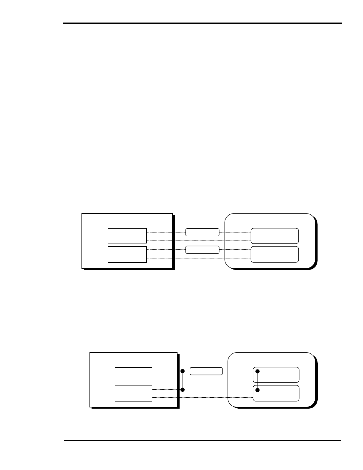
OPERATION
THREE-WIRE START GENERATORS
Three-wire start generators do not include automatic engine cranking control system. Separate
control of the starter m otor requires additional interaction between the inverter’s auto- control system and
the generator. This also adds complexity to the installation since more wires must be connected and
more programming of the inverter is required. Troubleshooting can also be more difficult.
The automatic control s ystem contr ols the starter much like a person does when star ting a car engine.
The starter is turned on for short periods of time and then turned off. If the engine starts up while cranking,
the starter is turned off af ter a 1/2-s ec ond delay. If the engine does not s tar t, the st arter is tur ned on again
after a delay period. This is repeated until either the generator starts or the m aximum number of start
attempts is reached.
The comm on term “three-wire start” m ay be misleading - the actual number of wires us ed may be four or
more. It simply means that c ontrol of the star ter motor is done separately from the generator. Mos t threewire start generators are not designed for automatic, unattended operation. T he generator supplier s hould
be consulted regarding additional safety components r equired for your installation. The automatic c ontrol
system only provides the starting and stopping signals based on what the batteries need. It will not shut off
the generator if a problem such as low oil pressure occurs.
Three-wire start type generators can be divided into two basic types - “Honda” types and “Onan” types.
The Honda type uses an automotive type starting circuit as previously discussed. O perating a switch that
is first turned to “RUN” and then m omentarily held to a “START” position starts it. Onc e the engine has
started, the switch is released and it retur ns to the “RUN” pos ition. To s hut down the generator, the switch
is placed in the “OFF” position. For this type of generator, relay RY7 duplicates the “RUN” position and
relay RY8 duplicates the “START” position, cranking the starter m otor. For this type of generator, select
RUN from the SET RY7 FUNCTION menu item under the GEN STARTING DETAILS (13) menu heading.
This is the default setting of this menu item.
GEN CONTROL RELAYS
COM
RY7
RY8
N.O.
COM
N.O.
5 AMP FUSE
5 AMP FUSE
HONDA TYPE GENERATOR
STOP SWITCH
CONTACTS
START SWITCH
CONTACTS
Figure 24, Three Wire Start Wiring Diagram (HONDA Type)
Onan type generators use a different starting sequenc e. Most Onan type generators use a three-pos ition
momentary type switch that controls their operation. To start the generator, the switch is held to the
“START” position. T his energizes the ignition system and cranks the starter motor. Onc e the engine has
started, the switch is released and it returns to a center off position. T he starter m otor then stops crank ing
but the ignition system remains energized. To shut down the generator, the switch is held to the “STOP”
position until the engine dies. Once the handle is released, it retur ns to the center pos ition. For this type of
generator, relay RY8 duplicates the “START” position and relay RY7 is used to duplicate the “STOP”
position (using the common and normally open contacts). Some gener ators use a sim ilar s ystem with two
push button switches - one to start and one to stop.
GEN CONTROL RELAYS
COM
RY7
RY8
N.O.
COM
N.O.
5 AMP FUSE
HONDA TYPE GENERATOR
STOP SWITCH
CONTACTS
START SWITCH
CONTACTS
Figure 25, Three-Wire Start Wiring Diagram (ONAN Type)
2001 Xantrex Technology, Inc.
5916 - 195th Street N. E.
Arlington, WA 98223
Telephone: 360/435-8826
Fax: 360/435-2229
www.traceengineering.com
SW Series Inverter/Charger
Part No. 2031-5
Rev. C: February 2001
Page
77
Page 86
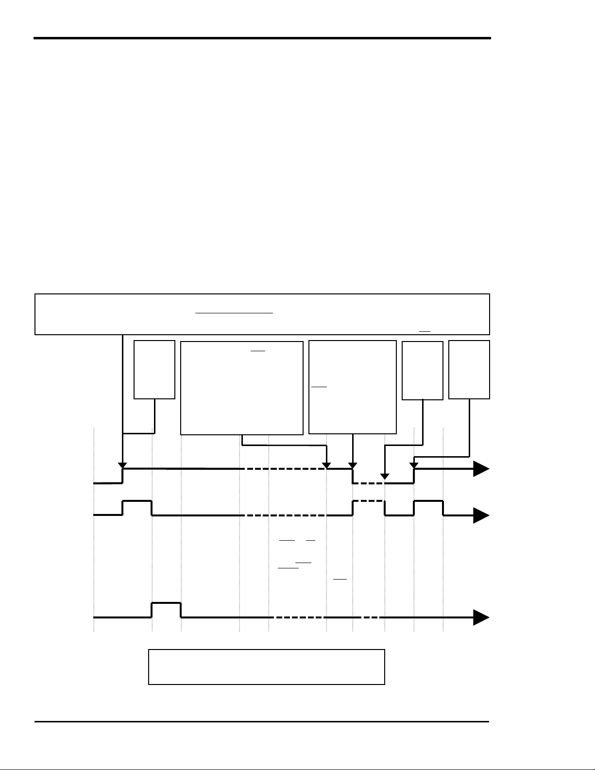
OPERATION
SW Series Inverter/Charger
Most diesel generators are controlled like the Onan type, except that they also require that glow plugs be
operated before the generator start is attempted. The SW Series Inverter/Charger automatic generator
control system can also provide glow plug control. The addition of an external relay may be required to
operate the glow plugs due to the amperage required by the glow-plugs and to separate the stop signal
circuit. For this type of generator, select GLOWSTOP from the SET RY7 FUNCTION menu item under the
GEN STARTING DETAILS (13) menu heading.
3-TO-2 WIRE CONVERTERS
Another option for three-wire start-type generators is a 3- to-2- wire conver ter which vary from simple relays
to advanced microprocessor types. Onan offers a simple 3-to- 2-wire converter that works well for m any
installations. Universal 3-to-2 wire converters can be us ed with virtually any generator as well as control
glow plugs for diesel generators. These also feature additional system components to signal the
generator control system to start.
GENERATOR CONTROL SEQUENCE
The relays close in a specific sequenc e to start the generator. Some of the timing periods are adj ustable
through the GEN STARTING DETAILS (13) menu heading. GLOWSTOP has been added to the
sequence for diesel generator applications . RY7 can be configured f or either “RUN” or “GLOWSTOP”
operation. The two control relays complete the following sequence:
The ’auto generator control sequence’ is initiated if the battery voltage remains bel ow the ’Set start volts DC’ setting (unless
’Start/End Quiet time h:m’ is enabled) for the required period of time or the ’Read LBCO 30 sec s tart VDC’ setting for 30 seconds;
or if the load amps reaches the ’Load Start amp AC’ setting longer than the ’Set Load Start delay min’ period. The manual
generator control sequence is in i t i ated if generator is manually turned on vi a ’Set Generator’ to ON.
RY7
RUN (or)
GLOW-
STOP
RY8
First ’auto
generator
start
attempt’
The auto generator stop sequence
is initiated if: (1) The battery
voltage has been held at the ’Set
Bulk volts DC’ setting for the ’Set
Absorption time h:m’ period or (2)
The load amps drops below the
’Load Start amps AC’ setting for
longer than the ’Set Load Stop
delay min’ period.
OFF OFF ON
OFF ON
START
SET PRE
CRANK
10 SECS.
DEFAULT
SET MAX
CRANKING
SECONDS
10 SECS
DEFAULT
(RY8 goes
off with a
1 sec delay
when
AC HOT IN
>80 VAC)
ON
DELAY
PERIOD
8 SECS
FIXED
SECONDS
ON (engages to the N.O. position)
OFF (engages to the N.C. position)
VAC
and
GEN-RUN PERIOD
(Determined by the
CHARGING’ heading
or by the current and
SET GEN
WARM-UP
SECONDS
60 SECS
DEFAULT
(Starts once
voltage
exceeds
80 VAC)
OFF (engages to the N.C. position)
LOCK ON
GOOD
DELAY
PERIOD
12 SECS
FIXED
(Starts when
AC is within
108 to 132
53-67 Hz)
voltage and ti me
settings under the
delay min settings
under the ’GEN
AUTO START
SETUP’ heading)
The generator will stop
immediately with an
inverter fault or if ’Set
Generator’ is set to
OFF. Also a "Kill Before
Cranking" signal is
enabled before the next
'auto generator start
DOWN
PERIOD
’BATTERY
40 SECS
FIXED
(Only used
with ’Set
Generator’ to
AUTO)
attempt'
COOL
ON ONOFF
Generator is
off and
waiting for
next ’auto
generator
start
sequence
START
DELAY
PERIOD
8 SECS
FIXED
Next ’auto
generator
Start
sequence
has been
initiated
SET PRE
SECONDS
10 SECS.
DEFAULT
Second
‘auto
generator
start
attempt’
CRANK
Time (Sec) 0 8 18 28 88 100 +100 +140 0 8 18
Figure 26, Relay RY7 and RY8 Sequence
Page
78
OFF = relay contact closed f rom N.C. to COM (relay disengaged)
ON = relay contact closed f rom N.O. to COM (relay engaged)
2001 Xantrex Technology, Inc.
5916 - 195th Street N. E.
Arlington, WA 98223
GEN CONTROL RELAYS
Telephone: 360/435-8826
Fax: 360/435-2229
www.traceengineering.com
Part No. 2031-5
Rev. C: February 2001
Page 87

OPERATION
GENERATOR STOP COOL DOWN PERIOD
When the autom atic generator stop system is used to st op the generator, the generator is disconnected
from the inverter first by opening the AC relay inside the inverter. This allows a very clean transition from
the generator to the inverter. The STO P signal is provided immediately if the generator is manually shut
off from the Control Panel. If the generator is shut of f automatically the generator will be allowed to run for
an additional 40 seconds before the STOP signal is provided. This allows the generator to cool down
before it is turned off. This is very important for turboc har ged generator s as it allows c ooler oil to r eac h the
turbo. If the generator does not stop after the 40 second cool down period when the stop signal is sent,
then the inverter will reconnect to the AC source and remain connected as long as it is available.
If the generator is stopped m anually from the Contr ol Panel, the generator is st opped im m ediately with no
cool down.
GENERATOR ERROR CAUSES
The red ERROR LED indicator will blink slowly if one of the following generator errors occurs:
• GEN UNDER/OVER SPEED: Indicates that the generator has synchronized with the inverter/charger
but the frequency is not well adjusted (63 - 67 on the high-end or 53 - 57 on the low end).
• GENERATOR START ERROR: The automatic control system will attempt to start the generator 5
times by closing the starting relay RY8 for up to the MAX CRANKING SECONDS setting, or the
inverter senses an AC voltage above 80-volts AC on the AC HOT IN 2 term inal. Once the inverter
senses 80 volts AC on the AC HOT IN 2 terminal, after a half-second delay, RY8 opens. After
successfully running for 5 minutes, the start attempts counter resets to zero. If the generator dies
within the 5-minute period of being started, the inverter will attempt to restart the generator. An
unsuccessful run is considered a failed start attempt. After 5 start attempts, the ERROR LED
illuminates and the generator control system shuts down. If the generator dies after successfully
running for 5 minutes, the start attempt c ounter will be reset to zero and the inverter will only restart
the generator if the auto start voltage setting or load amps AC setting is reached for the requir ed time
delay period.
• GENERATOR SYNC ERROR: Indicates that the generator was running but was not operating within
the voltage and frequency tolerances and not able to connect (out of sync), or the unit can not
maintain synchronization (AC voltage or frequency is out of tolerance).
• GEN MAX RUN TIME ERROR: Indicates that the generator ran for a period of time that exceeded the
SET MAXIMUM RUN TIME setting. This setting is intended to indicate exces sive generator operation
if the system has not been able to fully charge the battery. Operating heavy loads while charging, an
unstable generator or even low electrolyte levels in the battery can cause this. This m ay also occur
with systems that have very large batteries, requiring long charge periods, or systems with small
generators with limited battery-charging ability. If the default value results in repeated error c onditions,
increasing the SET MAXIMUM RUN TIME menu item setting m ay be necessary for your application.
When using the autom atic generator control system to complete a equalization cycle, the additional
time required for the EQ cycle should be consider ed in order to prevent reaching the SET MAXIMUM
RUN TIME menu item setting and causing a GEN MAX RUN TIME ERROR. This is an advisory error
only and does not stop the generator.
To clear a generator start error , access the SET GENERATOR menu item by pressing the green GEN
MENU button and move the cursor fr om AUTO or ON to OFF in the SET GENERATOR menu item. T his
clears all the generator error conditions and resets the start attempts counter.
2001 Xantrex Technology, Inc.
5916 - 195th Street N. E.
Arlington, WA 98223
Telephone: 360/435-8826
Fax: 360/435-2229
www.traceengineering.com
SW Series Inverter/Charger
Part No. 2031-5
Rev. C: February 2001
Page
79
Page 88

OPERATION
SW Series Inverter/Charger
EQUALIZATION CHARGING, AUTOMATIC GENERATOR CONTROL SYSTEM
An automatic equalization charge process is available in the SW Series Inverter/Charger. To start the
equalization process, select EQ from the SET GENERATOR menu item, accessible by pressing the green
GEN MENU button on the Control Panel.
During the next automatic generator run period, the inverter can be set to complete an equalization charge
process. You must first select EQ from the SET GENERATOR menu item. The generator will start the
equalization process the next time the generator is automatic ally started and will automatically stop and
return the cursor to the AUTO position in the SET GENERATOR menu item once the equalization period
has been completed.
The SET EQUALIZE TIME menu item under the BATTERY CHARGING (10) menu heading sets the
amount of time that the battery voltage must exceed the BULK VOLTS DC setting befor e the equalization
process is considered to be c ompleted. T his tim er is an acc umulating type timer that does not reset if the
voltage drops momentar ily below the bulk voltage setting. During the equalization process, the voltage will
be limited to the level of the SET EQUALIZATION VOLTS DC menu item.
During the equalization process, the BULK LED will flash slowly to indicate that the EQ position has been
selected from the SET GENERATOR menu item. When the proces s has f inished, the FLOAT LED will be
on if the generator or utility power is still available.
Page
80
2001 Xantrex Technology, Inc.
5916 - 195th Street N. E.
Arlington, WA 98223
Telephone: 360/435-8826
Fax: 360/435-2229
www.traceengineering.com
Part No. 2031-5
Rev. C: February 2001
Page 89

UTILITY BACKUP MODE
OPERATION
GENERATORUTILITY GRID
AC
MAIN
AC BREAKER
PANEL
AC
NON-CRITICAL
AC LOADS
AC AC
AC
INVERTER/
CHARGER
DC
BATTERY
ADDITIONAL
AC BREAKER
SUB-PANEL
AC
CRITICAL
AC LOADS
IN BRIEF
SW Series Inverter/Chargers provide an excellent utility system backup under the majority of powering
applications. Whenever a shorted grid condition affects voltage or frequency, the inverter disconnects
itself from the gr id and continues to suppor t the AC load using battery power. Typical transfer time under
a shorted grid condition is instantaneous.
Depending upon the type and amount of load, the transfer m ay, at times, be notic eable. T his is due to the
inverter’s output reaching the overcurrent trip level as it tr ies to maintain the load bef ore the internal relay
transfers to battery power.
To operate the system in utility backup mode:
• Connect utility AC power to the inverter's AC HOT IN 1 and NEUTRAL IN 1 terminals.
• Connect the AC loads to the inverter's AC HOT OUT and NEUTRAL OUT terminals.
• Adjust the battery charger parameters if the factory default values are not satisfactory. For UPS
applications with small battery banks, lower the battery-charging rate.
• Adjust the GRID (AC1) AMPS AC menu item to match the am perage of the cir cuit breaker s upplying
AC to the inverter input. This setting is loc ated in the AC INPUTS (11) menu heading - (See UTILITY
SUPPORT/OVERLOAD PROTECTION, on page 82).
2001 Xantrex Technology, Inc.
5916 - 195th Street N. E.
Arlington, WA 98223
Telephone: 360/435-8826
Fax: 360/435-2229
www.traceengineering.com
SW Series Inverter/Charger
Part No. 2031-5
Rev. C: February 2001
Page
81
Page 90

OPERATION
SW Series Inverter/Charger
UTILITY SUPPORT/OVERLOAD PROTECTION
This battery charger is very powerful and without limits could draw more current than is available fr om the
AC input source. When the utility grid is available, the grid has to power both the battery charger and any
AC loads connected. If AC charge curr ent combined with any AC load current exceeds the GRID (AC1)
AMPS AC menu item setting, the charge rate will be automatically reduced to keep from tripping the utility
grid breaker.
In addition, the inverter will support utility grid in the event that excessive loads threaten to trip the AC
breaker. If the am ount of power demanded by the AC loads is greater than the GRID (AC1) AMPS AC
menu item setting, the inverter will contribute power to operate the AC loads. This will limit the AC curr ent
drawn from the utility system.
This ability allows the utility line to be sized closer to the typical draw of the system, instead of being sized
to the maximum load. This m ay save considerable cost if a utility extension or upgrade is being installed.
The savings can even offset part or all of the inverter / battery system in some situations.
While the inverter is supporting the AC loads, the battery will be discharging. Typically, utility line support is
required for only short period of time during heavy power usage that will not cause the battery to be
significantly drained.
USING SLT MODE (SILENT MODE)
In SLT mode the batteries are charged only once a day, at a time prescribed in the BULK CHARGE
TRIGGER TIMER (15) menu heading. Selecting SLT in the SET GRID USAGE menu item, located under
the INVERTER SETUP (9) menu heading enables it. During the rest of the day the battery charger is
turned off and the utility grid powers the AC loads. If a utility outage occur s, the inverter turns on and r uns
the loads. When power r eturns, the inverter will return to the SLT mode after it has com pleted the Bulk
and Absorption stages of the battery charging process . The advantage of SLT m ode is silent operation
and slightly less power consumption under most conditions and quieter operation since the battery charger
is off most of the tim e. The disadvantage of SLT m ode is the loss of the natural power conditioning ability
of the inverter and the ability to “back off” the AC input which prevents overloading or circuit breaker
tripping (except during the time that the inver ter is c harging). T he trans ition from utility to inverter when an
outage occurs may also be more noticeable.
When using this mode, a START BULK TIME must be entered from the BULK CHARGE TRIGGER
TIMER (15) menu heading. If the tim er is defeated by setting it to 00:00, no bulk charging will take place
on a daily basis except immediately after a grid failure has occurred and the power has been restor ed.
The default setting is 00:00 that defeats the BULK CHARGE TRIGGER TIMER.
BATTERY REQUIREMENTS
Utility backup applications usually are designed to discharge the battery at a higher rate for a shorter
duration than alternative energy applications. Typically, batteries capacity ratings are for discharge periods
of 20 hours. This means that a 100-amp hour battery can deliver 5 amp hours for 20 hours. It cannot
deliver 100 amp hours for 1 hour . Battery manufactures can provide de-rating curves for their produc ts. If
the battery is not large enough, unsatisfactory performance may result. For the best performance,
oversizing of the battery is strongly recommended.
Page
82
2001 Xantrex Technology, Inc.
5916 - 195th Street N. E.
Arlington, WA 98223
Telephone: 360/435-8826
Fax: 360/435-2229
www.traceengineering.com
Part No. 2031-5
Rev. C: February 2001
Page 91

UTILITY INTERACTIVE MODE
OPERATION
UTILITY GRID
kWh METER
AC
OUTDOOR AC
DISCONNECT
BACKED UP
AC LOADS
SUB-PANEL
AC
AC
AC
MAIN AC LOADS
NOT PROVIDED
WITH BACK-UP
INVERTER/
CHARGER
DC
BATTERY
DC
SOLAR ARRAY
DC
GROUND FAULT
PROTECTION
DC
OVERVOLTAGE
PROTECTION
IN BRIEF
In this mode, SW Series Inverter/Charger s can be used to move power from the DC system into the AC
utility grid. This is often called “selling” power since the utility pays for the power you produce. It is
relatively simple to set the inverter up to accom plish this. However, this type of installation is so new that
many utility companies have not formalized their regulations regarding acceptable installations.
Regulations will vary from one utility to another. The utility companies have a right and a need to be
careful about how power is fed into their system. Utility interactive should be done with the assistance
of your dealer and must be done with the approval of the local utility company.
As a minimum, an outdoor mounted AC disconnect s hould be installed at the service entrance or nex t to
the utility meter. It should be clearly labeled “SOLAR ELECTRIC SYST EM AC DISCONNECT”. T his will
allow utility and emergency personnel to easily and safely isolate the system from the utility grid if required.
This disconnect should be lockable (by the utility) and installed between the AC HOT 1 INPUT of the
inverter and the circuit breaker in the AC load center connected to the utility grid. This allows the utility to
shut off the system if a problem occurs.
Since a utility interactive installation requires an understanding of your local utility code, lim ited diagrams
and details are included in this manual. Consult your utility or your local Xantrex dealer.
To operate the system in utility interactive mode, set-up the system as follows:
• Connect utility AC power to the inverter's AC HOT IN 1 and NEUTRAL IN 1 terminals.
• Connect the cr itical AC loads that are required to be backed-up, to the inverter ’s AC HOT OUT and
NEUTRAL OUT terminals.
• Use the GRID USAGE TIMER (18) and the BULK CHARGE TRIGGER TIMER (15) with the battery
charger parameters adj usted under the BATTERY CHARGING (10) menu heading to determine the
battery voltage level you require for your batteries.
• Select SELL from the SET GRID USAGE menu item in the INVERTER SETUP (9) menu heading.
• Adjust the GRID (AC1) AMPS AC menu item located in the AC INPUTS (11) menu heading (See
UTILITY SUPPORT/OVERL OAD PROTECTION, on page 82) to match the amperage of the circuit
supplying AC to the inverter input.
• Adjust the AC input voltage parameters using the SET INPUT LOWER LIMIT VAC and the SET
INPUT UPPER LIMIT VAC menu items, both located in the AC INPUTS (11) menu heading to match
the AC voltage requirements of your connected utility.
2001 Xantrex Technology, Inc.
5916 - 195th Street N. E.
Arlington, WA 98223
Telephone: 360/435-8826
Fax: 360/435-2229
www.traceengineering.com
SW Series Inverter/Charger
Part No. 2031-5
Rev. C: February 2001
Page
83
Page 92

OPERATION
SW Series Inverter/Charger
THEORY OF OPERATION
When SELL mode is selected from the SET GRID USAGE menu item located under the INVERTER
SETUP (9) menu heading in the SETU P MENU, the inverter will move any excess power not required to
charge the batteries into the utility grid.
In SELL mode, the inverter can be thought of as a battery charger that is able to operate in either direction
- it can send excess power fr om the battery back into the utility grid instead of drawing power fr om the
utility to charge the battery. To regulate the battery charging process, the inverter tak es DC power from
the solar array and converts it to AC power that supplies other AC loads through the utility grid. The
inverter is more accurately described as a utility interactive battery charger. This means that the inverter
will control battery voltage whenever utility power is connected and available. If a utility outage occurs, the
inverter can not control the battery voltage. Some external control must be provided by the system to
prevent damaging the battery as the solar array tries to overcharge the battery.
In a solar array configuration, a charge controller is not needed when the inverter is operational in SELL
mode and utility is connected. If the inverter was turned off, or utility power was to fail, the batteries could
quickly be over-charged. One of the inverter’s voltage controlled relays can be used to protect the
batteries in case of utility failure. It would be programmed to open an additional external relay that contr ols
the solar panels at a battery voltage above the battery charger’s BULK VOLTS DC setting. Please see the
OVERVOLTAGE PROTECTION FOR THE BATTERY section on page 89 for more information.
UTILITY INTERACTIVE ISLANDING PROTECTION
In utility interactive mode, the inverter is capable of detecting several types of failures.
• Grid shorted - Normally, when the utility power fails, the inverter momentarily tries to power the entir e
neighborhood. This condition looks like a short circuit to the inverter and causes it to reach the
overcurrent protection setting and shuts off. It then opens its internal relay and disconnects from the
utility grid. This protective system operates instantly.
• Grid open - The inverter can tell when there is no current being delivered to the grid and it will
disconnect. This is used when a disconnect switch is opened or the power line which feeds the
installation is cut. This protective system operates instantly.
• Islanding - This occurs when the grid has failed and the "neighbor hood" that the inverter is powering
requires a power level that the inverter can supply. This condition is called “islanding”. The islanding
detection circuit checks gr id condition on each c ycle. The inverter watches the utility grid and waits for
it to rise a couple of volts before it begins to invert again. This is done on each cycle when SELL
mode is activated. Typically, disconnect is achieved in a few cycles after the utility has failed. If a lar ge
electric motor is c onnected, it may provide enough generator capacity that the inverter think s the grid
is still connected. This c an fool this protective s ystem. T wo additional protec tive s ystems are provided
to then handle this condition, over/under frequency and over/under voltage detection.
• Over/Under Frequency - Since the inverter is locked onto the frequency of the utility grid, the
frequency of the islanding system will drift out of regulation in a short amount of time during an
islanding condition. This protective system may require a couple of seconds to respond. T he settings
are 58 and 62 Hertz for 60 Hertz models (48 and 52 Hertz for 50-Hertz models) and are not
adjustable.
• Over/Under Voltage - Since the inverter does not try to regulate the voltage of the utility grid while
selling power into it, the AC voltage will drift out of regulation in a short amount of time during an
islanding condition. This protective s ystem may require a couple of seconds to respond. T he default
settings are 108 VAC as the lower limit and 132 VAC as the upper limit. These settings are adjustable.
Page
84
2001 Xantrex Technology, Inc.
5916 - 195th Street N. E.
Arlington, WA 98223
Telephone: 360/435-8826
Fax: 360/435-2229
www.traceengineering.com
Part No. 2031-5
Rev. C: February 2001
Page 93

OPERATION
SELLING POWER - FROM A DC CHARGING SOURCE
The simplest and default operation of the SW Series Inverter/Charger in the SELL m ode is to “sell” the
excess power from the charging sourc e to the utility when the batteries are full. In this mode, the battery
voltage is held to the regulation level determined by the SET BATTERY SELL VOLTS DC setting. Since
the SET BATTERY SELL VOLTS DC setting is defaulted to the same value as the SET FLOAT VOLTS
DC setting, the inverter will sell the power f rom the charging source (wind, hydro or solar, etc.), but will
hold the battery at a charged level.
The regulation process can also be accomplished and allow the three stage charging (float, bulk and
absorption) of the batteries to occur each day by enabling the BULK CHARGE TRIGGER TIMER (15).
The batteries will be maintained at the SET FLOAT VOLTS DC setting until the SET START BULK TIME,
which will charge the batteries near the SET BULK VOLTS DC setting until the end of the ABSORPTION
TIME.
This operating mode offer s the individual system owner with several advantages. T he batteries would not
be cycled thereby increasing their life and the batteries would be fully charged in case of a power failure,
resulting in greater system efficiency.
Begin Day
00:00
Time
Float Volts
DC Volts
DC Volts
13.0
Charging from the DC
source (wind, hydro or
solar) has started
POSITIVE (+) = Inverter is drawing power from grid.
NEGATIVE (-) = Inverter is selling power to grid.
Input
amps AC 00
AC amps to grid (-)
AC amps from grid ( +)
AC amps
{
{
DC Setting
Set Float
Volts DC 13.4
Max Sell Amps
Set Max Sell
amps AC 30
LEGEND
Display/Settings
on Control Panel
Information
AC Setting
Bulk Charge Trigger Timer is
enabled (not the default setti ng)
Battery Sell Volts
DC Setting
Set Battery Sell
Volts DC 13.4
Sell to grid period
when the current from
the DC source is greater
than needed to maintain
the Float/Sell Volts DC
setting.
Charging from the DC
source (wind, hydro or
solar) has stopped
Max Charge
Amps AC Setting
Set Max Charge
amps AC 30
Set Start Bulk
time 20:00
Bulk Volts
DC Setting
Set Bulk Volts
DC 14.4
20:00
Set Absorption
time h:m 02:00
Absorption Time
Battery
charging from
grid has
started
End Day
23:59
Figure 27, Selling Power From A DC Charging Source; Hypothetical Time Of Day Operational History
2001 Xantrex Technology, Inc.
5916 - 195th Street N. E.
Arlington, WA 98223
Telephone: 360/435-8826
Fax: 360/435-2229
www.traceengineering.com
SW Series Inverter/Charger
Part No. 2031-5
Rev. C: February 2001
Page
85
Page 94

OPERATION
SW Series Inverter/Charger
started
SELLING POWER - STORED IN THE BATTERIES
Power stored in the batteries can also be sold into the utility grid. This can be used together with the solar
array or alone without a solar array. The inverter can be programm ed to sell the energy in the batteries at
a specific time and then to r echarge the batteries at another time. Both the discharge level and disc harge
rate can be adjusted to control the battery selling process.
Selling the power stored in the batteries can be used to level the output of the combined solar array and
battery system. This is beneficial during conditions of cloudy weather when the solar array output will vary
with each cloud that passes over. To set-up this ability, adjust the SET BATTERY SELL VOLTS DC menu
item under the BATTERY SELLING (17) menu heading for the maximum discharge voltage level
acceptable. The SET MAX SELL AMPS AC menu item should be set for the expected maximum output of
the solar array. Next, access the GRID USAGE TIMER (18) menu heading to allow setting of the time
period that the battery will be allowed to recharge during by adjusting the SET START CHARGE TIME and
SET END CHARGE TIME menu items. Outside of this time period, the inverter will sell the power stored in
the battery to the utility grid until the voltage reaches the BATTERY SELL VOLTS DC setting.
This mode can use the battery to maxim ize the output of the system during a specific period of time. An
example of these setting follows:
Begin Day
00:00
Time
Float Volts
DC Setting
Set Float
Volts DC 13.4
Charging from the
DC source (wind,
hydro or solar) has
started.
POSITIVE (+) = Inverter is drawing power from grid.
NEGATIVE (-) = Inverter is selling power to grid.
Input
amps AC 00
AC amps to grid (-)
AC amps from grid ( +)
{
{
Battery charging
from grid has
stopped
End charge
time 08:00
Set Float
Volts DC 13.4
DC Volts
AC amps
08:00
10:00
Battery Sell Volts
DC Setting
Set Battery Sell
Volts DC 12.4
Battery charging
from grid has
Start charge
time 18:00
Bulk Volts
DC Setting
Set Bulk Volts
DC 14.4
Max Sell
Amps Setting
Set Max Sell
amps 30
20:0018:00
Bulk charging
has started
Set Start Bulk
time 20:00
Set Absorption
time h: m 2:00
Absorption Time
Max Charge
Amps Setting
Set Max Charge
amps AC 30
End Day
23:59
LEGEND
Display/Settings
on Control Panel
Information
Figure 28, Selling Power Stored In The Batteries; Hypothetical Time Of Day Operational History
Page
86
2001 Xantrex Technology, Inc.
5916 - 195th Street N. E.
Arlington, WA 98223
Telephone: 360/435-8826
Fax: 360/435-2229
www.traceengineering.com
Part No. 2031-5
Rev. C: February 2001
Page 95

OPERATION
A system that includes 2400 watts of solar array is able to produce approximately 18 amps of AC power at
120 VAC. The output is most needed from 12:00 noon to 18:00 by the utility. If the GRID USAGE TIMER
is set to a START CHARGE TIME of 18:00 and a END CHARGE TIME of 12:00 noon, the inverter will sell
the battery from 12:00 noon to 18:00. The energy in the batteries will be used only if the solar array is not
able to provide enough power to reach the 18 amps AC ( determined by the MAX SELL AMPS AC setting
under the BATTERY SELLING MENU (17) menu heading. The battery will assist the solar array to meet
the 18 amps AC MAX SELL AMPS AC setting during the battery sell period. If the battery reaches the
SELL VOLTS DC setting during the sell period, the AC output current will slowly taper down to the solar
array’s output level and the battery will not be further discharged. At 18:00, the battery will c harge at the
rate allowed by the SET MAX CHARGE AMPS AC (2 amps AC is the lowest setting allowed). The batter y
will be recharged only to the FLOAT VOLTS DC setting unless the BULK CHARGE TRIGGER TIMER
(15) menu heading is used to trigger a bulk charge cycle.
This system offers the utility several advantages. The system can be relied on for a specific amount of
output at a set time. The AC output of the s ystem f rom 12 noon to 4 PM will not vary with the level of
sunlight (after all, the AC loads on the grid do not suddenly drop when a cloud passes over ). Only if it is
extremely cloudy will the system not produce its rated output for the full tim e period - which would not be
as important since the ambient temperature would not be as high.
This operating mode does not provide an individual system owner with m any added values. The wear and
tear on the batteries would be avoided and greater efficiency achieved if the standard sell mode was used.
BATTERY REQUIREMENTS
Batteries are required for utility inter-tie operation of this inver ter. The batteries can, however, be sm all if
the system does not provide back-up power in c ase of utility failure. T wo thousand watt/hours is suff icient
(100 amp/hours at 24 volts is 2400 watt hours). This can be achieved by using two “Group 27” sized
batteries for a 24-volt system. This is a very common size for RV and boat applications. Since the
batteries are not cycled excessively, sealed batteries may be used with good success.
CAUTION: If using gelled batteries, the battery charger must be set to the appropriate settings or
battery damage will occur.
BATTERY REGULATION LEVEL - SELL MODE
In the SELL mode, the regulation level of the battery is determ ined by the charge cycle (FLOAT or BULK)
and the settings of the BULK CHARGE TRIGGER TIMER (15) and the GRID USAGE TIME R (18).
The SET START CHARGE TIME menu item setting under the BULK CHARGE TRIGGER TIMER (15)
menu heading can be used to increase the battery charging regulation voltage to the SET BULK VOLTS
DC setting. The battery voltage will be held near the SET BULK VOLTS DC menu item setting under the
BATTERY CHARGING (10) menu heading for the adjustable ABSORPTION TIME period setting upon
encountering this BULK CHARGE TRIGGER TIMER event or after a loss of AC power to the AC HO T IN
1 input terminal.
The inverter will charge the battery to the FLOAT VOLTS DC setting at the START CHARGE TIME with
the GRID USAGE TIMER enabled (the START CHARGE TIME beginning time is not equal to the END
CHARGE TIME). This is indicated by the FLOAT LED indicator being on. After the END CHARGE TIME,
the inverter turns off the battery charger and begins to “sell” power into the utility grid from the battery (or
any other DC sources available and connected to the batteries) to the SELL VOLTS DC setting. The
FLOAT LED indicator blinking indicates this. The cu rrent will be limited to a max imum level c ontrolled by
the MAX SELL AMPS AC menu item setting under the BATTERY SELLING (17) menu heading.
With the GRID USAGE TIMER disabled (the SET START CHARGE TIME beginning time is equal to the
SET END CHARGE TIME) and the inverter in the FLOAT charge cycle, the inverter will use the utility grid
(or any other DC sources available and connected to the batteries) to m aintain the batteries to the SET
FLOAT VOLTS DC setting. This is indicated by the FLOAT LED indicator being on.
2001 Xantrex Technology, Inc.
5916 - 195th Street N. E.
Arlington, WA 98223
Telephone: 360/435-8826
Fax: 360/435-2229
www.traceengineering.com
SW Series Inverter/Charger
Part No. 2031-5
Rev. C: February 2001
Page
87
Page 96
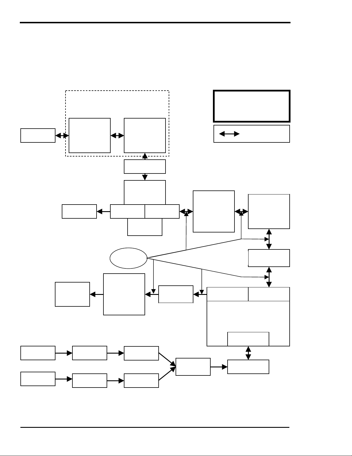
OPERATION
SW Series Inverter/Charger
UTILITY INTERACTIVE OPERATION WITH UTILITY BACKUP
The SW Series Inverter/Charger is capable of operating both as a utility interactive and a stand-alone
inverter. This allows the system to norm ally sell the excess power to the utility and, once an outage has
occurred, provide power to the AC loads from the battery.
The loads that will be provided with utility backup during outages must be isolated from the non-utility
backed-up loads. This usually requires the addition of an AC load center sub panel for the output of the
inverter.
UTILITY GRID
120/240 VAC
NOTE: THE BUY AND SELL METERS
kWh METER WITH
DETENTS (ONE-
WAY) 120/240
“BUY” METER
AC LOADS
120/240 VAC
CAN BE COMBINED
INTO ONE TWO-WAY METER
IF NET BILLING IS ALLOWED.
kWh METER WITH
DETENTS (ONE-
WAY) 120/240
VAC
“SELL” METER
AC DISCONNECT
(LOCKABLE)
120/240 VAC
BREAKER
60A/120 VAC
(FOR HOUSE)
#6 AWG
REQUIRED
VAC
SERVICE
ENTRANCE
PANEL
BREAKER
60A/120 VAC
CIRCUIT
BREAKERS
UTILITY INTERACTIVE
LINE-TIE SYSTEM WITH
BACKUP OF CRITICAL AC
(OPTIONAL)
kWh METER WITH
DETENTS (ONE-
WAY)
120 VAC
“PRODUCED”
METER
NEXT TO THE
INVERTER
LOADS
DESIGNATES
BI-DIRECTIONAL
CURRENT PATH
OUTDOORS NEXT
TO THE UTILITY
SERVICE
ENTRANCE
FUSED
DISCONNECT
60A/120 VAC
NEMA 3R
OUTDOOR TYPE
FUSED
DISCONNECT
60A/120 VAC
AC SUBPANEL
FOR UTILITY
BACK-UP AC
LOADS
“PRODUCED”
METER
CONTROLLER
PV CHARGE
CONTROLLER
FUSED
DISCONNECT
60A/120 VAC
NEXT TO THE
INVERTER
BATTERY
STORAGE
SYSTEM
AC OUTPUT
TERMINALS
WIND
GENERATOR
SOLAR
ARRAY
AC LOADS
TO BE
BACKED UP
120 VAC ONLY
FUSED
DISCONNECT
FUSED
DISCONNECT
Figure 29, Utility Interactive Line-Tie System With Battery Backup Flow Diagram
Page
88
2001 Xantrex Technology, Inc.
5916 - 195th Street N. E.
Arlington, WA 98223
Telephone: 360/435-8826
Fax: 360/435-2229
www.traceengineering.com
AC INPUT
TERMINAL
TRACE SW-SERIES
INVERTER/CHARGER
120 VAC
DC BATTERY
TERMINALS
BATTERY
DISCONNECT
Part No. 2031-5
Rev. C: February 2001
Page 97

OPERATION
OVERVOLTAGE PROTECTION FOR THE BATTERY IN SELL MODE
Normally, the inverter will regulate the charging process of the battery by selling ex cess power into the
utility grid. The battery will receive a three-stage charge r outine as previous ly described. If the utility grid is
not available (due to an outage or tripped AC input circuit breaker, etc.) or if the inverter s huts off, then the
inverter is not able to sell the excess power and the battery voltage will not be regulated, resulting in
possible overcharging of the battery.
Therefore, a separate contr ol is required to provide over voltage protection f or the battery when an outage
has occurred. The AUX Relays in the SW Series Inverter/Charger are designed to control an exter nally
connected power relay that would disconnect the solar arr ay and stop the charging process. The voltage
and hysteresis (difference between opening and closing voltage) are both adjus table. The external relay
can be either a standard mechanic al type or a mercury displacem ent type, depending on the voltage and
current required. The m ercury displacement type relay is usually required when the system voltage is 48
VDC or if the current of the solar array exceeds about 20 amps. Multiple relays can be used if the solar
array is divided into several source circuits (do not parallel relays for higher cur rent). Another option is to
use a charge controller such as the Trace™ C40. For more on the C40 MULTI-FUNCTION
CONTROLLER, see page 129.
A typically wiring configuration for this overvoltage protection is as follows:
SOLAR ARRAY
This circuit does draw a sm all am ount of power all of the tim e to power the coil of
the relay. Other circuits are possible but m ay have other drawbacks. This circuit
+P -N
provides protection against overcharging the batteries.
NORM.
OPEN
5 AMP
FUSE
AC OUTPUT - NEU
AC OUTPUT - HOT
SW - SERIES
INVERTER
AUX RELAY 9 COM.
AUX RELAY 9 N.C.
120VAC
COIL
-N
+P
+P -N
BATTERY BANK
Figure 30, Overvoltage Protection for Battery
AUX RELAYS
Three voltage-controlled relays are provided to simplify installations that have battery voltage related tasks
to perform. T hey are single pole double throw, five amp relays. Both the normally closed and normally
open contacts are available for each relay. The operation of the relays are individually controlled and
adjustable via the user menu. The battery voltage at which each of these relays are activated (SET
RELAY 9, 10 or 11 VOLTS DC) and the number of volts by which the battery voltage must drop before
the relay is de-activated (R9, R10 or R11 HYSTERESIS VOLTS DC) are both individually adjusted for
each relay. The three AUX Relays operate independently of the inverter or charger. For location and wiring
information on the AUX Relays, see the AUXILIARY AND GENERATOR CONTROL RELAY section on
page 14.
CAUTION: These relays are not intended to direc tly control a load or charging source - rather
they can be used to send a signal or operate the coil of another higher amperage device which
does the actual switching of the power. A fuse rated at 5 amps or less should be included to
protect each of the relays. Damage to these relays from overloading is not cov ered by warranty
and requires the inverter to be returned to a repair center. This also applies to the generator
control relays.
2001 Xantrex Technology, Inc.
5916 - 195th Street N. E.
Arlington, WA 98223
Telephone: 360/435-8826
Fax: 360/435-2229
www.traceengineering.com
SW Series Inverter/Charger
Part No. 2031-5
Rev. C: February 2001
Page
89
Page 98
OPERATION
SW Series Inverter/Charger
ENERGY MANAGEMENT MODE
UTILITY GRID
AC
INVERTER/
CHARGER
AC
AC LOADS
DC
BATTERY
IN BRIEF
The purpose of this mode is to manage how utility power is used. One method is to char ge the batteries at
a favorable time and then use the power later. This is often desirable when time of day metering is
available. A solar array is not required, but can be used to reduce the dis c har ging of the batter y. Since the
most expensive power is often during the afternoon, the solar array may be a valuable addition. This mode
is an alternative to utility interactive systems. This mode does not involve “selling” power into the utility grid
and therefore does not usually require the approval of the utility. The same system is also able to operate
as a utility back-up system to provide power when an outage occurs.
In order to disconnect from the grid during a specif ic period of the day and operate only as an inverter, a
window of time is created during which battery charging is allowed. Outside this window, the inverter will
power the load from the battery. If the battery gets low, the system will transfer back to the utility and
recharge the battery.
To operate the system in Energy Management Mode, set up the system as follows:
• Connect utility AC power to the inverter’s AC HOT IN 1 and NEUTRAL IN 1 terminals.
• Connect AC loads to the inverter’s AC HOT OUT and NEUTRAL OUT terminals.
• Set the GRID (AC1) AMPS AC menu item, in the AC INPUTS (11) menu heading, to match the
amperage of the circuit supplying AC to the inverter input (See UTILITY SUPPORT/OVERLOAD
PROTECTION on page 82).
• Set the SET GRID USAGE menu item, under the INVERTER SETUP (9) menu heading, to FLT.
• Set the SET START CHARGE TIME menu item, under the GRID USAGE TIMER (18) menu heading,
to the time the inverter connects to the utility. This is the beginning of the time the battery charger is
allowed to operate and the end of the inverter operating period.
• Set the SET END CHARGE TIME menu item, under the GRID USAGE TIMER (18) menu heading, to
the time that the inverter disconnects from grid and begins to run the loads from the battery. At this
time, the battery charger will stop charging. If the battery voltage falls to the LOW BATTERY
TRANSFER VDC menu item setting during the inverter operating time period, the AC loads will be
reconnected to the utility grid and the battery will be charged to the FLOAT VOLTS DC or LOW
BATTERY CUT IN VDC setting, whichever is lower. This prevents over-discharging the battery. The
battery will be charged until the next END CHARGE TIME is reached.
• Set the START BULK TIME menu item under the BULK CHARGE TRIGGER TIMER (15) menu
heading to a time after the START CHARGE TIME menu item s etting. T his allows delaying of the bulk
charge cycle to a later time. Before the bulk charge is started, the battery will be charged only to the
float voltage level. The START BULK TIME is usually set to occur during the lowest cost rate per iod.
Adjusting the SET FLOAT VOLTS DC menu item to just above the normal at res t voltage ( 12.6 VDC)
will reduce the amount of charging that occurs in the between time periods, yet will allow limited
charging to prevent sulfation of the battery while being partially discharged.
Page
90
2001 Xantrex Technology, Inc.
5916 - 195th Street N. E.
Arlington, WA 98223
Telephone: 360/435-8826
Fax: 360/435-2229
www.traceengineering.com
Part No. 2031-5
Rev. C: February 2001
Page 99

OPERATION
The system should be designed so that the battery is able to operate the loads for the entire peak rate
period without reaching the low battery transfer voltage. This may require that heavy loads be operated
only during the non-peak rate period.
This mode may be advantageous when the utility offers time-of-day metering that allows you to buy power
at a variable rate during different time periods. For exam ple, the rate may be only $0.04 per kilowatt-hour
from midnight to 6 AM, but $0.16 during the peak period from noon to 6 PM. The in-between periods might
cost $0.08 per kilowatt-hour. The idea is to not use utility power during the peak period and to charge the
battery at night, during the off-peak period. A solar arr ay is not required but, since it produces the most
power during the peak period, it will reduce the amount of power required from the battery.
The greater the difference between the peak and off-peak rates, the gr eater the value of this operating
mode. W hen com bined with a solar array, this mode m ay be more ec onom ic than operating the s ystem in
low battery transfer mode.
If the battery is full and power is available from the solar array, it will be used to directly power the AC
loads connected to the inverter output, even though the utility grid is also connected to the loads. If the
amount of power exceeds the AC loads connected, the battery voltage will increase. An external solar
array controller is required to limit the battery voltage to a safe level and to prevent overcharging and
possible damage to the battery when only light loads are being powered.
Note: The round-trip net energy efficiency of charging and discharging a Deep Cycle battery rarely
exceeds 50%. In order for this tec hnique to be cost ef f ective, the off -peak r ate f oe elec tricity should be no
more than half of the on-peak rate. The cost of battery replacement should also be calculated and
included when evaluating this technique.
To program the inverter for the example above:
• Set the SET GRID USAGE menu item, under the INVERTER SETUP (9) menu heading, to FLT.
• Set the START CHARGE TIME menu item, under the GRID USAGE TIMER (18) menu heading, to 6
PM (18:00).
• Set the END CHARGE TIME menu item, under the GRID USAGE TIMER (18) menu heading, to
NOON (12:00).
• Set the SET START BULK TIME menu item, under the BULK CHARGE TRIGGER TIMER (15) menu
heading, to a time after MIDNIGHT (00:30) to delay most of the recharging for the cheapest period.
• Setting the SET FLOAT VOLTS DC menu item, under the BATTERY CHARGING (10) menu
heading, to the nominal full battery voltage level will reduce the amount of battery charging that occur s
between time periods, yet will allow limited charging to prevent sulfation of the battery while sitting
partially discharged.
2001 Xantrex Technology, Inc.
5916 - 195th Street N. E.
Arlington, WA 98223
Telephone: 360/435-8826
Fax: 360/435-2229
www.traceengineering.com
SW Series Inverter/Charger
Part No. 2031-5
Rev. C: February 2001
Page
91
Page 100

OPERATION
SW Series Inverter/Charger
PEAK LOAD SHAVING MODE
UTILITY GRID
AC
INVERTER/
CHARGER
AC
AC LOADS
DC
BATTERY
IN BRIEF
The inverter can also be used to lim it the maximum draw the AC loads place on the utility grid. Many
utilities impose a surchar ge on their custom ers bas ed on the peak load used by a fac ility. The SW Series
Inverter/Charger can be configured to provide all of the power above a specified level, eliminating the
surcharges. With the Control Panel, simply adjust the SET GRID (AC1) AMPS AC menu item to the
maximum value allowed by the utility without the peak load surchar ge. All AC loads mus t be connected to
the output of the inverter through the 60-amp AC transfer relay located internally. Multiple inverters may be
required for larger applications with individual groups of loads connected to each inverter. This can be
used in addition to time of day metering and still allows the invert er to provide a utility back-up f unction in
addition.
This mode is als o useful for applications where AC loads r equire more power than a utility connection is
able to supply. This often occurs in mobile applications where only a 15-amp outlet may be available. The
inverter can provide the excess power above the 15 am ps when the load is operating. If this condition
occurs intermittently, then the inverter will be able to recharge the batteries between the heavy load
periods. This can elim inate the need to increase the size of a utility supply circuit, providing substantial
savings that can offset the cost of the inverter.
This mode is used in some vehicle applications to im prove the power quality by reducing the load placed
on the AC line cord. The inverter provides the “start-up” power to eliminate brown out problems
experienced when starting air conditioners, etc. This also prevents tripping AC source circuit breakers
when heavy loads are operating.
Page
92
2001 Xantrex Technology, Inc.
5916 - 195th Street N. E.
Arlington, WA 98223
Telephone: 360/435-8826
Fax: 360/435-2229
www.traceengineering.com
Part No. 2031-5
Rev. C: February 2001
 Loading...