

Page 1
Internal RS-232 Interface
for XT/HPD Series
Programmable DC
Power Supplies
RS232-XT
RS232-HPD
Operating Manual
Page 2

Page 3

Operating Manual for
Internal RS-232 Interface
for XT 60 Watt and
HPD 300 Watt Series
Programmable DC
Power Supplies
Page 4

Limited
Warranty
What does this warranty cover and how long does it last?
This Limited Warranty is provided by Xantrex Technology, Inc. (“Xantrex”) and
covers defects in workmanship and materials in your RS-232 Interface Card. This
warranty lasts for a Warranty Period of 5 years from the date of purchase at point of
sale to you, the original end user customer.
What will Xantrex do?
Xantrex will, at its option, repair or replace the defective product free of charge,
provided that you notify Xantrex of the product defect within the Warranty Period,
and provided that Xantrex through inspection establishes the existence of such a
defect and that it is covered by this Limited Warranty.
Xantrex will, at its option, use new and/or reconditioned parts in performing
warranty repair and building replacement products. Xantrex reserves the right to use
parts or products of original or improved design in the repair or replacement. If
Xantrex repairs or replaces a product, its warranty continues for the remaining
portion of the original Warranty Period or 90 days from the date of the return
shipment to the customer, whichever is greater. All replaced products and all parts
removed from repaired products become the property of Xantrex.
Xantrex covers both parts and labor necessary to repair the product, and return
shipment to the customer via a Xantrex-selected non-expedited surface freight
within the contiguous United States and Canada. Alaska and Hawaii are excluded.
Contact Xantrex Customer Service for details on freight policy for return shipments
outside of the contiguous United States and Canada.
How do you get service?
If your product requires troubleshooting or warranty service, contact your merchant.
If you are unable to contact your merchant, or the merchant is unable to provide
service, contact Xantrex directly at:
Phone: 604 422 8595
Toll Free North America: 1 800 667 8422
Fax: 604 421 3056
Email: info@xantrex.com
ii Operating Manual for RS-232 for XT/HPD Series Power Supply
Page 5

Direct returns may be performed according to the Xantrex Return Material
Authorization Policy described in your product manual. For some products, Xantrex
maintains a network of regional Authorized Service Centers. Call Xantrex or check
our website to see if your product can be repaired at one of these facilities.
In any warranty claim, dated proof of purchase must accompany the product and the
product must not have been disassembled or modified without prior written
authorization by Xantrex.
Proof of purchase may be in any one of the following forms:
• The dated purchase receipt from the original purchase of the product at point of
sale to the end user, or
• The dated dealer invoice or purchase receipt showing original equipment
manufacturer (OEM) status, or
• The dated invoice or purchase receipt showing the product exchanged under
warranty
What does this warranty not cover?
This Limited Warranty does not cover normal wear and tear of the product or costs
related to the removal, installation, or troubleshooting of the customer’s electrical
systems. This warranty does not apply to and Xantrex will not be responsible for any
defect in or damage to:
a. the product if it has been misused, neglected, improperly installed, physically
damaged or altered, either internally or externally, or damaged from improper
use or use in an unsuitable environment;
b. the product if it has been subjected to fire, water, generalized corrosion,
biological infestations, and high input voltage from lightning strikes;
c. the product if repairs have been done to it other than by Xantrex or its authorized
service centers (hereafter “ASCs”);
d. the product if it is used as a component part of a product expressly warranted by
another manufacturer;
e. the product if its original identification (trade-mark, serial number) markings
have been defaced, altered, or removed.
Release 1.1 iii
Page 6

Disclaimer Product
THIS LIMITED WARRANTY IS THE SOLE AND EXCLUSIVE WARRANTY PROVIDED
BY XANTREX IN CONNECTION WITH YOUR XANTREX PRODUCT AND IS, WHERE
PERMITTED BY LAW, IN LIEU OF ALL OTHER WARRANTIES, CONDITIONS,
GUARANTEES, REPRESENTATIONS, OBLIGATIONS AND LIABILITIES, EXPRESS
OR IMPLIED, STATUTORY OR OTHERWISE IN CONNECTION WITH THE PRODUCT,
HOWEVER ARISING (WHETHER BY CONTRACT, TORT, NEGLIGENCE, PRINCIPLES
OF MANUFACTURER’S LIABILITY, OPERATION OF LAW, CONDUCT, STATEMENT
OR OTHERWISE), INCLUDING WITHOUT RESTRICTION ANY IMPLIED WARRANTY
OR CONDITION OF QUALITY, MERCHANTABILITY OR FITNESS FOR A
PARTICULAR PURPOSE. ANY IMPLIED WARRANTY OF MERCHANTABILITY OR
FITNESS FOR A PARTICULAR PURPOSE TO THE EXTENT REQUIRED UNDER
APPLICABLE LAW TO APPLY TO THE PRODUCT SHALL BE LIMITED IN DURATION
TO THE PERIOD STIPULATED UNDER THIS LIMITED WARRANTY.
IN NO EVENT WILL XANTREX BE LIABLE FOR ANY SPECIAL, DIRECT, INDIRECT,
INCIDENTAL OR CONSEQUENTIAL DAMAGES, LOSSES, COSTS OR EXPENSES
HOWEVER ARISING WHETHER IN CONTRACT OR TORT INCLUDING WITHOUT
RESTRICTION ANY ECONOMIC LOSSES OF ANY KIND, ANY LOSS OR DAMAGE TO
PROPERTY, ANY PERSONAL INJURY, ANY DAMAGE OR INJURY ARISING FROM OR
AS A RESULT OF MISUSE OR ABUSE, OR THE INCORRECT INSTALLATION,
INTEGRATION OR OPERATION OF THE PRODUCT.
Exclusions If this product is a consumer product, federal law does not allow an exclusion of
implied warranties. To the extent you are entitled to implied warranties under federal
law, to the extent permitted by applicable law they are limited to the duration of this
Limited Warranty. Some states and provinces do not allow limitations or exclusions
on implied warranties or on the duration of an implied warranty or on the limitation
or exclusion of incidental or consequential damages, so the above limitation(s) or
exclusion(s) may not apply to you. This Limited Warranty gives you specific legal
rights. You may have other rights which may vary from state to state or province to
province.
iv Operating Manual for RS-232 for XT/HPD Series Power Supply
Page 7

Information WITHOUT LIMITING THE GENERALITY OF THE FOREGOING, UNLESS
SPECIFICALLY AGREED TO BY IT IN WRITING, XANTREX
a. MAKES NO WARRANTY AS TO THE ACCURACY, SUFFICIENCY OR SUITABILITY
OF ANY TECHNICAL OR OTHER INFORMATION PROVIDED IN MANUALS OR
OTHER DOCUMENTATION PROVIDED BY IT IN CONNECTION WITH THE
PRODUCT; AND
b. ASSUMES NO RESPONSIBILITY OR LIABILITY FOR LOSSES, DAMAGES,
COSTS OR EXPENSES, WHETHER SPECIAL, DIRECT, INDIRECT,
CONSEQUENTIAL OR INCIDENTAL, WHICH MIGHT ARISE OUT OF THE USE OF
SUCH INFORMATION.
THE USE OF ANY SUCH INFORMATION WILL BE ENTIRELY AT THE USER’S RISK.
WARNING:
Limitations
on Use
Please refer to your product user manual for limitations on uses of the product.
Specifically, please note that this power supply is not intended for use in connection
with life support systems and Xantrex makes no warranty or representation in
connection with any use of the product for such purposes.
Xantrex Technology, Inc.
8999 Nelson Way
Burnaby, British Columbia
Canada V5A 4B5
Information
About Your
Power
Supply
Please record the following information when you first open your Power Supply
package:
Model Number ______________________________________________
Serial Number ______________________________________________
Purchased From ______________________________________________
Purchase Date ______________________________________________
Release Release 1.1 (2002-06)
Copyright © 2002 Xantrex Technology Inc. All rights reserved.
Printed in Canada
Release 1.1 v
Page 8
Power
!
!
Supply
Safety
WARNING—High Energy and High Voltage
Exercise caution when using and calibrating a power supply. High energy levels
can be stored at the output voltage terminals on a power supply in normal
operation. In addition, potentially lethal voltages exist in the power circuit and on
the output and sense connectors of a power supply with a rated output greater
than 40 V. Filter capacitors store potentially dangerous energy for some time after
power is removed.
CAUTION
Operate the power supply in an environment free of flammable gases or fumes.
To ensure that the power supply’s safety features are not compromised, use the
power supply as specified in this manual and do not substitute parts or make any
unauthorized modifications. Contact the service technician for service and repair
help. Repairs must be made by experienced service technicians only.
Warnings,
Cautions,
and Notes
Warnings, cautions, and notes are defined and formatted in this manual as shown
below.
WARNING
Describes a potential hazard which could result in injury or death, or, a procedure
which, if not performed correctly, could result in injury or death.
CAUTION
Describes a procedure which, if not performed correctly, could result in damage
to data, equipment, or systems.
Note
Describes additional operating information which may affect the performance of the
equipment.
vi Operating Manual for RS-232 for XT/HPD Series Power Supply
Page 9

About This Manual
This technical manual is for the RS-232 Interface, a microprocessor-controlled
option card for all models of XT and HPD Series DC output power supplies. This
manual provides you with specifications, user options, and configuration
instructions for the interface, along with a command set which allows you to control
your power supply from a computer console. Error messages and calibration
procedures are also included.
This manual is designed for the user who is familiar with basic electrical theory
especially as it applies to the operation of power supplies. This implies a recognition
of Constant Voltage and Constant Current operation modes and the control of input
and output power, as well as the observance of safe techniques while effecting supply
or pin connections and any changes in switch settings. The user should also have
experience with a computer-based communications software package.
Refer to your power supply manual for installation, configuration, and operating
procedures for your power supply.
Main Sections
Section 1 Features and Specifications Describes the interface and lists its
features and specifications.
Section 2 Installation and Configuration Gives basic setup procedures.
Describes inspection, cleaning, shipping, and storage procedures.
Section 3 Operation Lists the complete command set, status registers, and error
codes.
Section 4 Calibration Provides detailed procedures for voltage and current
mode calibration as well as over voltage protection (OVP) calibration. Includes
calibration for programming and readback accuracy.
Manual Revisions
The current release of this manual is listed below. Updates may be issued as an
addendum.
Release 1.1 (2002-06)
Release 1.1 vii
Page 10

About This Manual
viii Operating Manual for RS-232 for XT/HPD Series Power Supply
Page 11

Contents
About This Manual . . . . . . . . . . . . . . . . . . . . . . . . . . . . . . . . . . . . . . . . . . . . . . . . . . . vii
Section 1.
Features and
Specifications
Section 2.
Installation
and
Configuration
Description . . . . . . . . . . . . . . . . . . . . . . . . . . . . . . . . . . . . . . . . . . . . . . . . . . . . . . . . . 11
Features and Functions . . . . . . . . . . . . . . . . . . . . . . . . . . . . . . . . . . . . . . . . . . . . . . . 12
Features. . . . . . . . . . . . . . . . . . . . . . . . . . . . . . . . . . . . . . . . . . . . . . . . . . . . . . . 12
Programmable Functions. . . . . . . . . . . . . . . . . . . . . . . . . . . . . . . . . . . . . . . . . . 12
Readback Functions . . . . . . . . . . . . . . . . . . . . . . . . . . . . . . . . . . . . . . . . . . . . . 12
Specifications . . . . . . . . . . . . . . . . . . . . . . . . . . . . . . . . . . . . . . . . . . . . . . . . . . . . . . . 13
Introduction. . . . . . . . . . . . . . . . . . . . . . . . . . . . . . . . . . . . . . . . . . . . . . . . . . . . . . . . . 15
Initial Inspection . . . . . . . . . . . . . . . . . . . . . . . . . . . . . . . . . . . . . . . . . . . . . . . . . . . . . 15
Basic Setup Procedure. . . . . . . . . . . . . . . . . . . . . . . . . . . . . . . . . . . . . . . . . . . . . . . . 19
Communications . . . . . . . . . . . . . . . . . . . . . . . . . . . . . . . . . . . . . . . . . . . . . . . . . . . . .21
Baud Rate Selection . . . . . . . . . . . . . . . . . . . . . . . . . . . . . . . . . . . . . . . . . . . . . 21
Flow Control Selection . . . . . . . . . . . . . . . . . . . . . . . . . . . . . . . . . . . . . . . . . . . . 22
Software Flow Control . . . . . . . . . . . . . . . . . . . . . . . . . . . . . . . . . . . . . . . . . . . . 22
Hardware Flow Control . . . . . . . . . . . . . . . . . . . . . . . . . . . . . . . . . . . . . . . . . . . 23
Connections . . . . . . . . . . . . . . . . . . . . . . . . . . . . . . . . . . . . . . . . . . . . . . . . . . . . 24
Transmit / Receive Pin Selection . . . . . . . . . . . . . . . . . . . . . . . . . . . . . . . . . . . . 24
Removing the cover . . . . . . . . . . . . . . . . . . . . . . . . . . . . . . . . . . . . . . . . . . . . . . 24
Remote/Local Operation. . . . . . . . . . . . . . . . . . . . . . . . . . . . . . . . . . . . . . . . . . . . . . .25
Remote / Local Switch . . . . . . . . . . . . . . . . . . . . . . . . . . . . . . . . . . . . . . . . . . . . 25
LOC Command . . . . . . . . . . . . . . . . . . . . . . . . . . . . . . . . . . . . . . . . . . . . . . . . . 25
Local Mode Disable Jumper J95 . . . . . . . . . . . . . . . . . . . . . . . . . . . . . . . . . . . . 25
Remote Mode Operation . . . . . . . . . . . . . . . . . . . . . . . . . . . . . . . . . . . . . . . . . . 26
Local Mode Operation . . . . . . . . . . . . . . . . . . . . . . . . . . . . . . . . . . . . . . . . . . . . 26
RS-232 Connection . . . . . . . . . . . . . . . . . . . . . . . . . . . . . . . . . . . . . . . . . . . . . . . . . .27
Power Supply Settings . . . . . . . . . . . . . . . . . . . . . . . . . . . . . . . . . . . . . . . . . . . . . . . . 28
User Options and Settings . . . . . . . . . . . . . . . . . . . . . . . . . . . . . . . . . . . . . . . . . . . . . 29
OVP Selection . . . . . . . . . . . . . . . . . . . . . . . . . . . . . . . . . . . . . . . . . . . . . . . . . . 29
TTL Shutdown . . . . . . . . . . . . . . . . . . . . . . . . . . . . . . . . . . . . . . . . . . . . . . . . . .30
User Signals . . . . . . . . . . . . . . . . . . . . . . . . . . . . . . . . . . . . . . . . . . . . . . . . . . . . . . . . 31
Connector J7 User Signals . . . . . . . . . . . . . . . . . . . . . . . . . . . . . . . . . . . . . . . . 31
J7 Cable Connection . . . . . . . . . . . . . . . . . . . . . . . . . . . . . . . . . . . . . . . . . . . . . 32
Section 3. Operation
Release 1.1 ix
Introduction. . . . . . . . . . . . . . . . . . . . . . . . . . . . . . . . . . . . . . . . . . . . . . . . . . . . . . . . . 35
RS-232 Operation. . . . . . . . . . . . . . . . . . . . . . . . . . . . . . . . . . . . . . . . . . . . . . . . . . . . 35
Command Syntax . . . . . . . . . . . . . . . . . . . . . . . . . . . . . . . . . . . . . . . . . . . . . . . . . . . . 35
Manual Conventions . . . . . . . . . . . . . . . . . . . . . . . . . . . . . . . . . . . . . . . . . . . . . 35
Command Format and Parameters . . . . . . . . . . . . . . . . . . . . . . . . . . . . . . . . . . 36
Command Strings . . . . . . . . . . . . . . . . . . . . . . . . . . . . . . . . . . . . . . . . . . . . . . .38
Command Terminators . . . . . . . . . . . . . . . . . . . . . . . . . . . . . . . . . . . . . . . . . . . 38
Order . . . . . . . . . . . . . . . . . . . . . . . . . . . . . . . . . . . . . . . . . . . . . . . . . . . . . . . . . 38
Page 12

Contents
Command Summary . . . . . . . . . . . . . . . . . . . . . . . . . . . . . . . . . . . . . . . . . . . . . . . . . 39
Command Reference. . . . . . . . . . . . . . . . . . . . . . . . . . . . . . . . . . . . . . . . . . . . . . . . . 42
Accumulated Status, Status, and Fault Registers . . . . . . . . . . . . . . . . . . . . . . . . . . . 49
Error Codes . . . . . . . . . . . . . . . . . . . . . . . . . . . . . . . . . . . . . . . . . . . . . . . . . . . . . . . . 51
Troubleshooting . . . . . . . . . . . . . . . . . . . . . . . . . . . . . . . . . . . . . . . . . . . . . . . . . . . . . 52
Diagnostic LEDs . . . . . . . . . . . . . . . . . . . . . . . . . . . . . . . . . . . . . . . . . . . . . . . . 52
Section 4.
Calibration
Introduction . . . . . . . . . . . . . . . . . . . . . . . . . . . . . . . . . . . . . . . . . . . . . . . . . . . . . . . . 53
Voltage Mode Calibration. . . . . . . . . . . . . . . . . . . . . . . . . . . . . . . . . . . . . . . . . . . . . . 54
Voltage Calibration Setup . . . . . . . . . . . . . . . . . . . . . . . . . . . . . . . . . . . . . . . . . 54
Voltage Program Calibration Procedure . . . . . . . . . . . . . . . . . . . . . . . . . . . . . . 54
Voltage Readback Calibration Procedure . . . . . . . . . . . . . . . . . . . . . . . . . . . . . 55
Current Mode Calibration. . . . . . . . . . . . . . . . . . . . . . . . . . . . . . . . . . . . . . . . . . . . . . 56
Current Calibration Setup . . . . . . . . . . . . . . . . . . . . . . . . . . . . . . . . . . . . . . . . . 56
Current Program Calibration Procedure . . . . . . . . . . . . . . . . . . . . . . . . . . . . . . 56
Current Readback Calibration Procedure . . . . . . . . . . . . . . . . . . . . . . . . . . . . . 57
Over Voltage Protection (OVP) Calibration . . . . . . . . . . . . . . . . . . . . . . . . . . . . . . . . 58
x
Operating Manual for RS-232 for XT/HPD Series Power Supply
Page 13
Section 1. Features and Specifications
Description
The RS-232 Interface is a microprocessor-controlled option card for all models of
the XT and HPD Series of DC output power supply. Installed internally, the RS-232
interface card gives you remote digital control of simple test systems. It features fast,
16-bit resolution for programming and readback and uses bit serial protocol for
sending data between the computer and the interface. The RS-232 interface has an
extensive command set and uses most of the user-programmable features employed
by all of our interfaces.
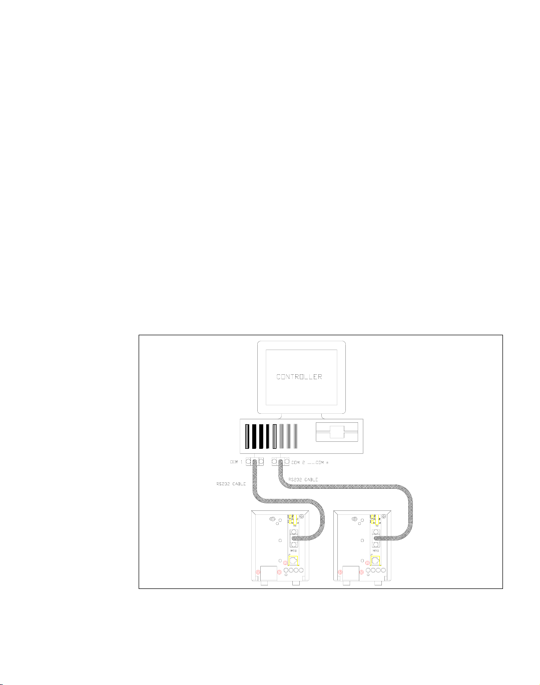
In addition to the RS-232 port and its interface, this remote control application
requires a computer-based communications software package such as PROCOMM,
XTALK, Windows Terminal Program, equivalent communications software, or low
level or high level language programs. The RS-232 interface is an ideal tool for
reliable, remote power supply control of both research and development
applications.
Figure 1.1 Sample Configuration using RS-232 Interface
Release 1.1 11
Page 14

Features and Specifications
Features and Functions
Features and Functions
Features • 16-bit programming and readback of voltage and current
• Programmable over voltage protection with reset
• Easy-to-use, self-documenting command set
• User-programmable isolated fault, polarity, isolation, and auxiliary, user-defined
output signals.
• LED status signals: error, address, remote/local operation, and over voltage
protection.
• Foldback in CV or CC mode with reset
• Software calibration
Programmable
Functions
Readback
Functions
• Output voltage and current
• Soft limits for voltage and current
• Over voltage protection
• Output enable/disable
• Maskable fault interrupt
• Hold and trigger
• Output relay signals
• Actual voltage and current
• Voltage and current settings
• Soft voltage and current limits
• Over voltage protection setting
• Present and accumulated power supply status
• Programming error codes
• Fault codes
• Power supply model and software version identification
12 Operating Manual for RS-232 for XT/HPD Series Power Supply
Page 15

Features and Specifications
Specifications
The specifications in this section are warranted at 25°C ±5°C unless otherwise
specified. All specifications are subject to change without notice.
Table 1.1 Specifications for XT 60 W Series Supply with RS-232 Interface Installed
Models 7-6 15-4 20-3 30-2 60-1 120-0.5 250-0.25
Program Resolution
Voltage
Current
OVP
Program Accuracy
Voltage
Current
OVP
Readback Resolution
Voltage
Current
Readback Accuracy
Voltage
Current
1. Apply accuracy specifications according to the following voltage program accuracy example:
Set a model XT 15-4 power supply to 10 volts.
The expected result will be within the range of 10 volts ± 20mV ± 0.1% of the set voltage of 10 volts.
1
1
1.1mV
1.0mA
1.0mV
10mV
±0.1%
110mA
±0.15%
70mV
1.1mV
1.0mA
10mV
±0.15%
110mA
±0.15%
2.4mV
0.6mA
2.4mV
20mV
±0.1%
70mA
±0.15%
150mV
2.4mV
0.6mA
10mV
±0.1%
70mA
±0.15%
3.1mV
0.5mA
3.1mV
20mV
±0.15%
50mA
±0.15%
200mV
3.1mV
0.5mA
10mV
±0.1%
50mA
±0.15%
4.7mV
0.3mA
4.7mV
30mV
±0.15%
40mA
±0.15%
300mV
4.7mV
0.3mA
15mV
±0.1%
40mA
±0.15%
9.3mV
0.2mA
9.3mV
200mV
±0.15%
26mA
±0.2%
600mV
9.3mV
0.2mA
35mV
±0.15%
26mA
±0.2%
17mV
0.1mA
17mV
400mV
±0.15%
13mA
±0.2%
1.2V
17mV
0.1mA
70mV
±0.15%
13mA
±0.2%
34mV
0.08mA
34mV
800mV
±0.15%
7mA
±0.2%
2.4V
34mV
0.08mA
140mV
±0.15%
7mA
±0.2%
Specifications
Release 1.1 13
Page 16

Features and Specifications
Specifications
Tab le 1.2 Specifications for HPD 300 W Series Supply with RS-232 Interface Installed
Models 15-20 30-10 60-5
Program Resolution
Voltage
Current
OVP
Program Accuracy
Voltage
Current
OVP
Readback Resolution
Voltage
Current
Readback Accuracy
Voltage
Current
1. Apply accuracy specifications according to the following voltage program accuracy example:
Set a model HPD 15-20 power supply to 10 volts.
The expected result will be within the range of 10 volts ± 20mV ± 0.1% of the set voltage of
10 volts.
2.4mV
2.8mA
2.4mV
1
60mV
±0.1%
75mA
±0.12%
150mV
2.4mV
2.8mA
1
45mV
±0.3%
75mA
±0.12%
4.7mV
1.4mA
4.7mV
70mV
±0.1%
50mA
±0.12%
300mV
4.7mV
1.4mA
90mV
±0.3%
40mA
±0.12%
9.3mV
0.7mA
9.3mV
90mV
±0.12%
25mA
±0.1%
600mV
9.3mV
0.7mA
175mV
±0.3%
25mA
±0.1%
14 Operating Manual for RS-232 for XT/HPD Series Power Supply
Page 17

Section 2. Installation and Configuration
!
Introduction
To use this product, you must have the following equipment:
• a compatible model of DC output power supply
• serial extender cable (straight through)
• computer with an RS-232 interface (serial port)
• computer-based communications software package
The RS-232 interface is usually installed at the factory. Your local distributor or
service center can also install the interface, especially for use in a
previously-purchased supply already on site. The RS-232 interface card will be
calibrated and configured with default settings. You will need to configure the supply
for your system using the “Basic Setup Procedure” on page 19. Refer also to
Figure 2.1, on page 16, Figure 2.2, on page 16 and Figure 2.3, on page 17 for
drawings of the front panel, the interface subplate, and the RS-232 interface printed
circuit board (PCB).
Initial Inspection
CAUTION
If you remove the unit's cover, use proper static control techniques to avoid damage
to static-sensitive components on the printed circuit board.
On first receiving your unit, perform a quick physical check.
• Ensure each package contains a power supply with its RS-232 interface board
installed, and manuals for the power supply and the RS-232 interface. Any
additional parts shipped with the power supply will be identified in the supply's
documentation.
• Inspect the unit for any signs of physical damage such as scratches, cracks, or
broken switches, connectors, or displays.
• Check the printed circuit board and components if you suspect internal damage.
If the unit is damaged, save all packing materials and notify the carrier immediately.
For additional information, please see the section titled, “Returning Power Supplies
to the Manufacturer” in the manual shipped with your complete unit.
Release 1.1 15
Page 18
Installation and Configuration
Initial Inspection
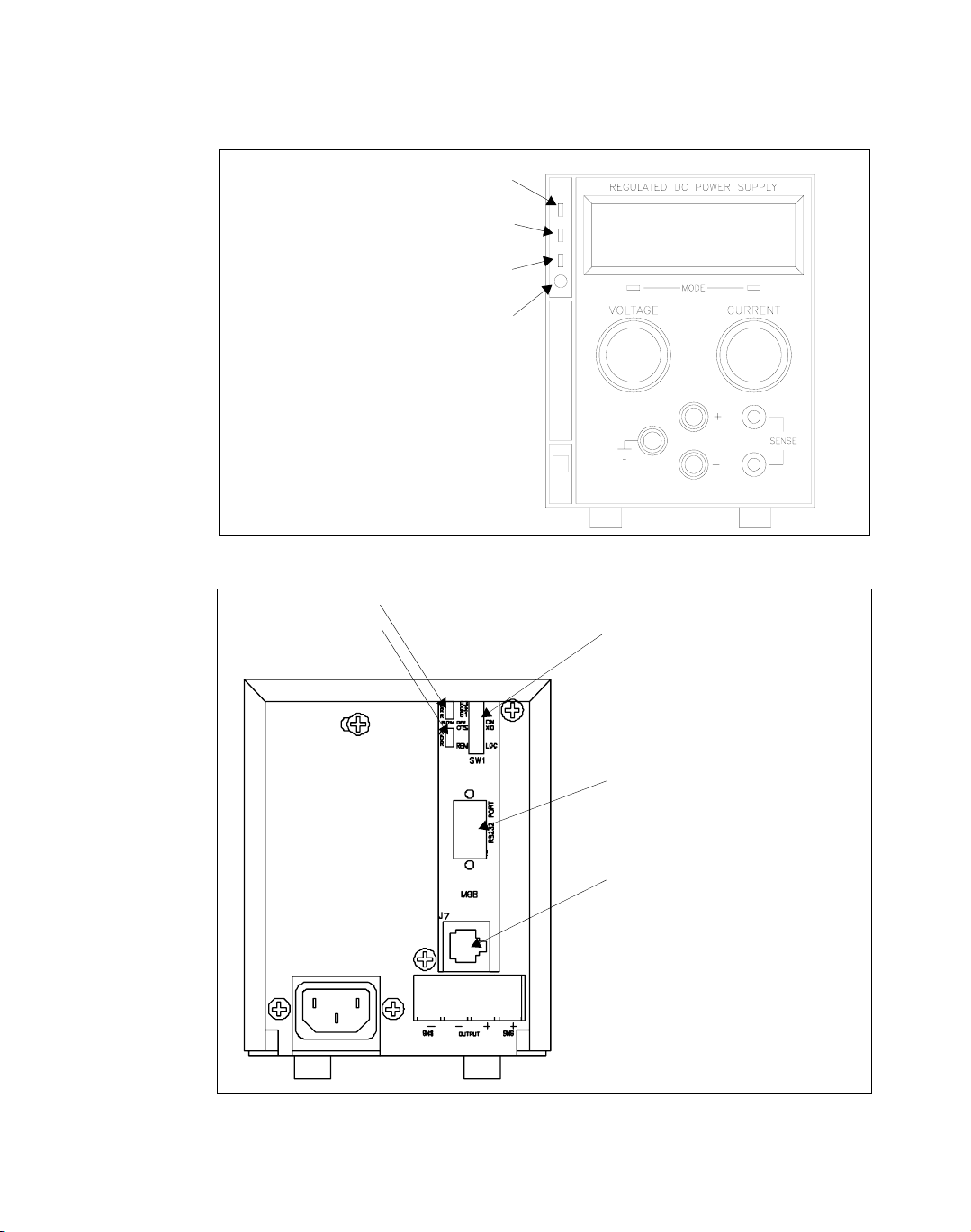
Over Voltage Protection (OVP) LED
Figure 2.1 Power Supply Front Panel with RS-232 Interface Installed
Remote Mode (REM) LED
Service Request (SRQ) LED
GPIB Only
OVP Potentiometer
Error LED (ERR)
Address LED (ADR)
0
1
SW1 Switch
1 Remote/Local Mode Selection
2,3 Not Used
4 CTS/XO Flow Control Selection
5 Flow ON/OFF Selection
6-8 B1-B3 Baud Rate Selection
RS-232 Connector
J7 User Signal Connector
Figure 2.2 Power Supply Rear Panel with RS-232 Interface Installed
16 Operating Manual for RS-232 for XT/HPD Series Power Supply
Page 19
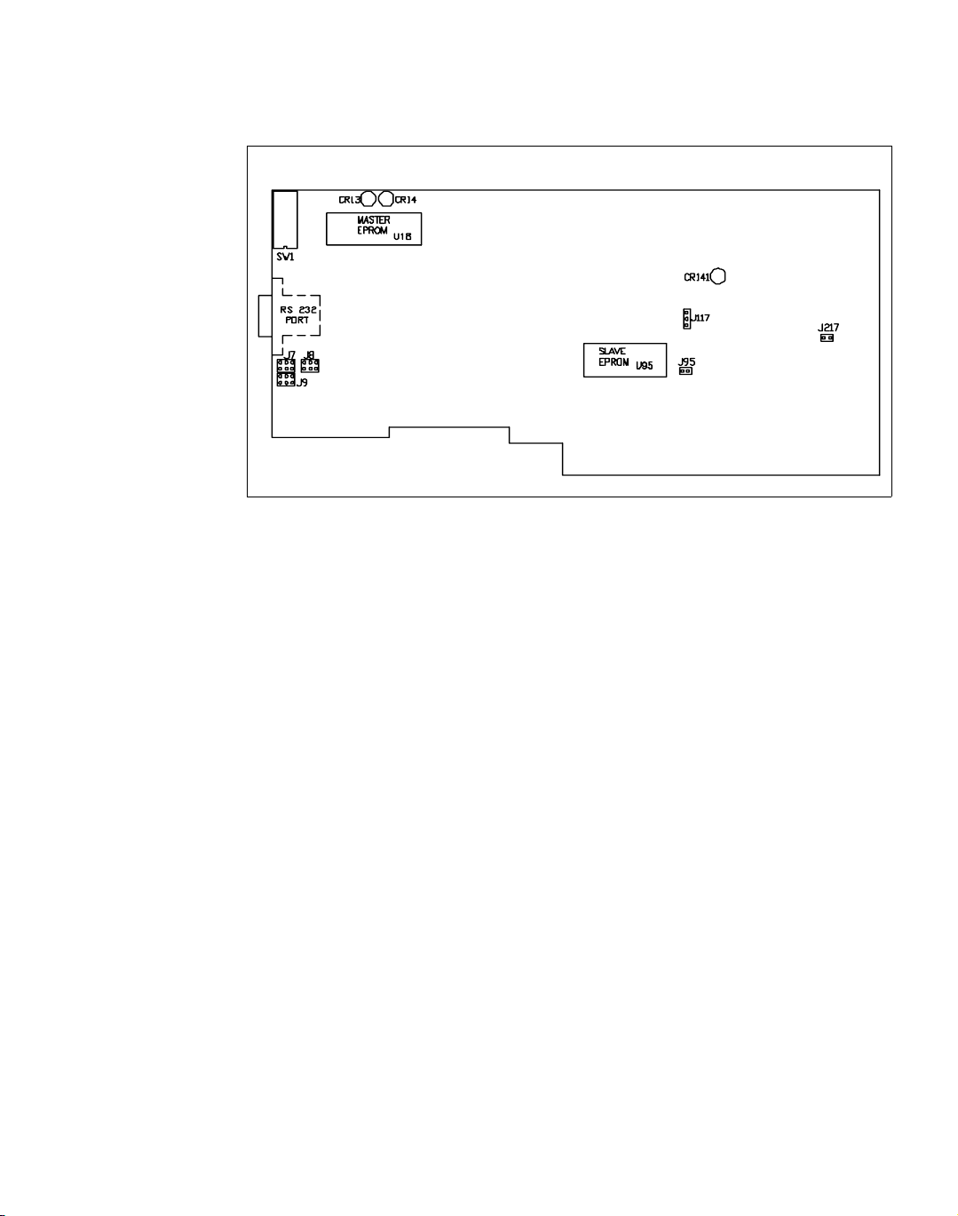
Figure 2.3 RS-232 Interface PCB
See next page for designation descriptions.
Installation and Configuration
Initial Inspection
Release 1.1 17
Page 20

Installation and Configuration
Initial Inspection
JUMPER SELECTION
J95 Local OVP control selection
J117 User TTL shutdown (S/D)
selection
J217 Remote OVP Control Selection
J7 RS-232 (J5) transmit and
receive pin selection
J8 RS-232 flow control selection of
RTS/CTS (ready to send/clear
to send) or DTR/DSR (data
terminal ready/data set ready)
J9 RS-232 flow control selection of
RTS/CTS or DTR/DSR
Note: All other jumpers are not user-selectable.
LED INDICATORS
[closed] [default]. See
[open] See
[1-2] User TTL S/D line active low.
[2-3] [default] User TTL S/D line active high.
[closed] [default]. See
[open] See
[3-1] Transmit on pin 3 [default]
[4-6] Receive on pin 2 [default]
[3-5] Transmit on pin 2
[4-2] Receive on pin 3
[2-4][3-5] [default] RTS input on pin 7 (used with
CTS output on pin 8)
[2-4][1-3] DTR input on pin 4 (used with DSR
output on pin 6)
[1-3][4-6] [default] CTS output on pin 8 (used
with RTS input on pin 7)
[3-5][4-6] DSR output on pin 6 (used with DTR
input on pin 4)
Table 2.13, on page 29.
Table 2.13, on page 29.
page 29.
page 29.
CR141 Red Diagnostic LED Bus error or soft restart on Slave circuitry.
CR14 Red Diagnostic LED Soft restart on Master circuitry.
CR13 Green Diagnostic LED Bus error on Master circuitry.
EPROMS
U95 Slave EPROM See revision number stamped on EPROM.
U18 Master EPROM See revision number stamped on EPROM.
Figure 2.3, RS-232 Interface PCB continued.
18 Operating Manual for RS-232 for XT/HPD Series Power Supply
Page 21

Basic Setup Procedure
This procedure can be used as a quick reference for those familiar with the
configuration requirements for the RS-232 interface as installed in the DC power
supply. For those who want more information, each step refers to more detailed
procedures located in subsequent sections. Execute each step of the procedure in the
sequence given.
The RS-232 standard is a commonly-used serial communications protocol that
defines how to transmit data between a computer and a programmable instrument. It
uses a point-to-point communication protocol with a transmitter sending data to a
receiver, one bit at a time, over a single communication line. Serial communication
is accessible via the serial ports on most computers.
For proper communication through the RS-232 serial interface, you need to specify
various parameters so that your data is sent and received by the controller (computer)
and the device (power supply) in the same manner. To set the RS-232 option for
operation, follow the setup procedure in Table 2.1.
Installation and Configuration
Basic Setup Procedure
Release 1.1 19
Page 22

Installation and Configuration
Basic Setup Procedure
Table 2. 1 Setup Procedure
Step # Description Action Reference
1 Baud Rate
Selection
2 Flow Control
Selection
3 Remote/Local
Operation
4 RS-232
Connection
5 User Signal
Connector
6 Power ON Power on the unit. Before proceeding,
7 Power Supply
Settings
8 Test Test the link by communicating with the
Select transmission speed See
page 21
Set flow control ON or OFF. If flow
control is set ON, choose
software-based XON/XOFF or
hardware-based CTS/RTS (Clear to
Send/Ready to Send) or DTR/DSR
(Data Terminal Ready/Data Set Ready)
communication control.
Use the rear panel REM/LOC switch to
select remote or local state of the power
supply.
Connect the RS-232 cable assembly to
the supply at connector J4.
Configure and use the J7 connector
signals, if required.
check to ensure that the green REMOTE
LED on the front panel is on.
Configure the controller’s operating
parameters to match the power supply
settings.
power supply.
“Flow Control Selection” on page
22
See
page 25
See
page 27
See “Connector J7 User Signals”
on page 31
See
on page 29 and “User Signals” on
page 31
Local/Remote OVP, TTL Shutdown,
and auxiliary connector J7 user
signals.
See
page 28.
Example: VSET2;ISET1
This command string sets power
supply voltage to 2V and its current
limit to 1A.
See Section 3.
“Baud Rate Selection” on
.
“Remote/Local Operation” on
“RS-232 Connection” on
“User Options and Settings”
“Power Supply Settings” on
.
.
.
for information about
20 Operating Manual for RS-232 for XT/HPD Series Power Supply
Page 23

Communications
Installation and Configuration
Communications
Baud Rate
Selection
Serial transmission sends and receives data in bit streams at fixed bit rates. Both the
computer and the interface must have the same bit rate setting for proper
communication. Use switches B1, B2, and B3 on the rear panel SW1 switch to select
the power supply's rate of transmission in bits per second. Table 2.2, “Switch S1
Settings for Baud Rate”summarizes the switch settings with the reference markings
on the rear panel subplate. Refer to Figure 2.2, on page 16 for the location of the
SW1 switch on the RS-232 interface subplate.
Table 2.2 Switch S1 Settings for Baud Rate
Baud Rate B1 B2 B3
9600 0 0 0
4800 0 0 1
2400 0 1 0
1200 0 1 1
600 100
300 101
150 110
75 111
0 = OPEN/OFF 1 = CLOSED/ON
Note:When resetting switches B3, B2, and B1 during a working session, turn the
power supply OFF and then ON again to put the new settings into effect.
Release 1.1 21
Page 24

Installation and Configuration
Communications
Flow Control
Selection
Flow control signals regulate data flow for proper communication. Use the
FLOW switch on the rear panel S1 switch to select flow control or to disable
flow control. With flow control enabled, you can use either software or hardware
protocols to control flow rates. Table 2.3 gives the FLOW switch settings with
regards to the markings on the subplate rear panel. For a diagram of the rear
panel subplate, see Figure 2.2, on page 16.
Table 2.3 Flow Control Section
FLOW Switch Setting Condition
0 Disable Flow Control
1 Enable Flow Control
Once you select the flow control option, you have to select either software flow
control or hardware flow control using the CTS/XO switch (SW1-4) on the rear
panel of the power supply. Software flow control uses XON/XOFF protocol
while with hardware flow control you have the choice of RTS/CTS or DTR/DSR
protocol. Table 2.4 shows the flow control conditions in reference to the
CTS/XO switch. To change the hardware flow control protocol, refer to Table
2.3 in this section. Figure 2.2, “Power Supply Rear Panel with RS-232 Interface
Installed” on page 16 shows the location of the SW1 switch on the power supply
rear panel.
Table 2.4 Hardware/Software Flow Control Selection
XON Switch Setting Condition
0
1
Hardware Flow Control
Software Flow Control
Software
Flow Control
This software protocol uses special characters that synchronize device
communications. The device sends the control code XOFF (ASCII value 13 hex)
when it is not ready to receive data. The device sends the control code XON
(ASCII value 11) when it is ready to resume receiving data.
To choose XON/XOFF protocol, select the XON switch position shown in Table
2.4.
22 Operating Manual for RS-232 for XT/HPD Series Power Supply
Page 25

Installation and Configuration
Communications
Hardware
Flow Control
Hardware flow control protocol requires a dedicated control line on the RS-232
cable. The dedicated control line is needed so that the device can signal the
controller when it is ready to receive data. You can designate either RTS/CTS or
DTR/DSR protocol for the RS-232 interface.
Set the XON switch for hardware control using the information in Table 2.4. With
hardware flow control selected, RS-232 Interface PCB jumpers J8 and J9 dictate
the type of flow protocol. Table 2.5, “Jumper/Pin Settings for RTS/CTS Flow
Control (Default)” and Table 2.6, “Jumper/Pin Settings for DTR/DSR Flow
Control (Default)” identify jumper connections and input and output pin
designations for each protocol. See also “Transmit / Receive Pin Selection” on
page 24 for RS-232 connector pinouts.
Note:When resetting the flow control switches during a working session, turn the
power supply OFF and then ON again to put the new settings into effect.
Table 2.5 Jumper/Pin Settings for RTS/CTS Flow Control (Default)
Jumper Connections RS-232 Connector Pin
RTS (Input to RS-232)
CTS (Output to RS-232)
Table 2.6 Jumper/Pin Settings for DTR/DSR Flow Control (Default)
DTR (Input to RS-232)
DSR (Output to RS-232)
J8 to 2-4 and 3-5
J9 to 1-3 and 4-6
Jumper Connections RS-232 Connector Pin
J8 to 2-4 and 1-3
J9 to 3-5 and 4-6
7
8
4
6
Release 1.1 23
Page 26

Installation and Configuration
Communications
Connections Use a 9-pin (DB9) to 9-pin parallel cable to connect the interface card to the serial
port on the host computer. If you need to use a 25-pin connector (DB25) on the host
interface, ensure the correct connections are made by referring Table 2.7. If the
proper cables are not available and you need to change the transmit/receive pin
configuration, see “Transmit / Receive Pin Selection”.
Table 2.7 Transmit/Receive Pin Connections
Power Supply (DCE) Host Computer (DTE)
9-pin connector
Pin 2 transmits to Pin 2 (Receive)
Pin 3 receives from Pin 3 (Transmit)
Pin 5 (Ground) connects to Pin 5 (Ground)
25-pin connector
Pin 2 transmits to Pin 3 (Receive)
Pin 3 receives from Pin 2 (Transmit)
Pin 5 (Ground) connects to Pin 7 (Ground)
Transmit /
Receive Pin
Selection
Removing the
cover
The RS-232 interface can use either pin 2 or pin 3 of the RS-232 connector to
transmit or receive data. You can set the pin orientation you want by changing the
position of the J7 jumper on the interface PCB. Table 2.8, “Jumper Settings for
Transmit/Receive Pin Selection” shows the transmit/receive pin selection on the
RS-232 connector in relation to the settings of the J7 jumper. See Figure 2.3,
“RS-232 Interface PCB” on page 17 to locate jumper J7.
Table 2.8 Jumper Settings for Transmit/Receive Pin Selection
Jumper J7 Connections RS-232 Connector Pin
Transmit (TXD)
Receive (RXD)
4-6 (default)
4-2
3-1 (default)
3-5
3
2
2
3
In order to access the J7 jumper or the J95 jumper (see page 25) you will need to
remove the cover. First, turn the unit upside-down and remove the 6 small screws
(3 to each side) on the bottom of the power supply. Turn the unit back up the right
way. Hold the plastic front panel firmly and lift the metal cover slightly back and
up. The front panel should disengage from the cover. Now, holding the cover
straight, slide it towards the back of the unit, along the runners, until it comes fully
off.
24 Operating Manual for RS-232 for XT/HPD Series Power Supply
Page 27

Remote/Local Operation
Installation and Configuration
Remote/Local Operation
Remote /
Local Switch
LOC
Command
Local Mode
Disable
Jumper J95
Use the rear panel Remote/Local switch, SW1-1, to toggle between remote and
local operation without losing the programmed values. See Table 2.9 for the switch
settings.
Table 2.9 Remote/Local Start-up Settings.
Switch Position Power ON results
0, OPEN (REM) Unit in remote mode
1, CLOSED (LOC) Unit in local mode
Ensure the rear panel REM/LOC switch is set for remote mode. When the switch
is set for remote mode, you can use the LOC command to toggle between remote
mode and local mode. See “Command Reference” on page 42.
You can disable local control of the power supply by removing jumper J95 on the
PCB. We recommend that you remove jumper J95 only if you never plan to control
the power supply from the front panel. When the Local Mode Disable Jumper J95
is closed, you can select between operating the power supply in either local mode
or remote mode by using the rear panel remote/local switch or by using the
software LOC command. With jumper J95 open, you can only operate the power
supply in remote mode. Opening the J95 jumper disables the rear panel
remote/local switch and the front panel voltage and current knobs. You cannot
return to local mode using the LOC command without closing jumper J95.
Table 2.10 Local Mode Disable Jumper J95 Selection.
Jumper J95 Position Operating State
Closed Remote or local control of power supply
Open Software control only
Note:The location of over voltage protection control is dependent on the position
of jumper J95 and of OVP control jumper J217. Table 2.13, “OVP Control Mode
Selection,” on page 29 shows how jumper position affects the location of OVP
control.
Release 1.1 25
Page 28

Installation and Configuration
Remote/Local Operation
Table 2.11 Remote Mode Power On Conditions
Condition Default Settings 60 W 7-6 Model Example
Voltage 0 V VSET 0
Current 0 A ISET 0
Soft Voltage Limit VMAX (see models) VMAX 7
Soft Current Limit IMAX (see models) IMAX 6
OVP Trip Voltage Model VMAX + 10% OVSET 7.7
Delay 0.5 s DLY 0.5S
Foldback Protection OFF FOLD OFF
Output ON OUT ON
Hold OFF HOLD OFF
Unmask NONE UNMASK NONE
AUXA OFF AUXA OFF
Remote Mode
Operation
Local Mode
Operation
AUXB OFF AUXB OFF
While in remote mode, use the interface commands to control the output of the
power supply from a computer. See Section 3 for a complete list of
device-dependent commands available with this interface.
In local mode operation, you set the voltage and current output levels and the OVP
trip level with controls located on the front panel. Refer to the operating manual for
a description of the functions available at the front panel.
26 Operating Manual for RS-232 for XT/HPD Series Power Supply
Page 29
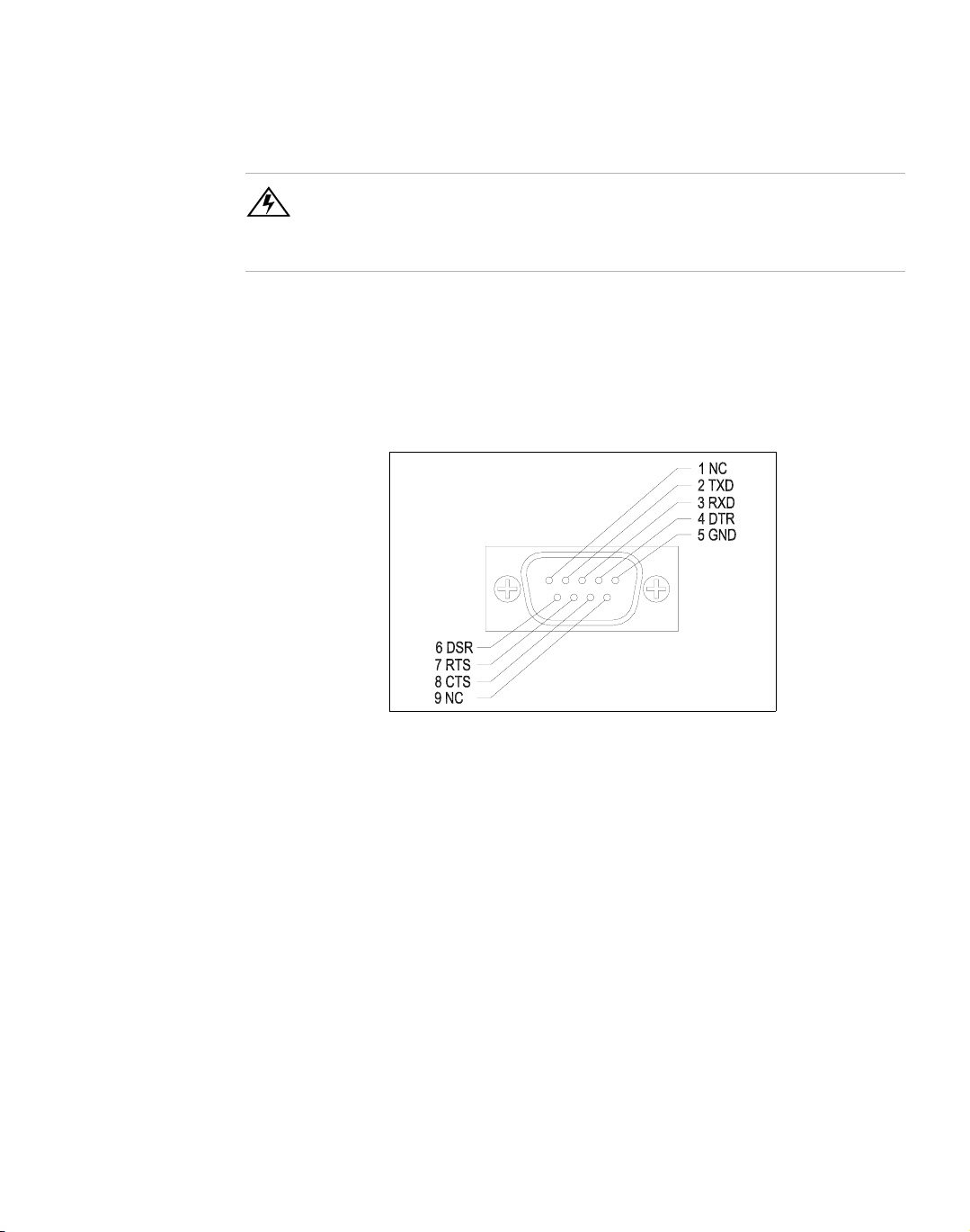
RS-232 Connection
Use an approved RS-232 connector and cable when connecting the RS-232
Interface to your computer. The RS-232 connector uses the 9 pin mating connector
J4 on the rear panel. Figure 2.4 shows the connector pinouts for the RS-232
connector. Refer to Figure 2.2, on page 16 for the position of the RS-232 connector
on the rear panel subplate.
Installation and Configuration
RS-232 Connection
WARNING
Do not operate the power supply and the computer at significantly different frame
potentials. The interface connection system may not be capable of handling the
resulting excessive ground currents.
Figure 2.4 RS-232 Connector (J4) Pinouts (default configuration)
Release 1.1 27
Page 30

Installation and Configuration
Power Supply Settings
Power Supply Settings
For serial communication, the computer and the RS-232 interface must share the
same communication settings. Make sure that the settings of the computer and of
the power supply agree with those shown in Table 2.12.
Table 2.12 Power Supply Settings
Parameter Setting
Transmission
Mode Full Duplex
Speeds 75, 150, 300, 600, 1200, 2400, 4800, 9600
Parity None
Connector DB9-pin Male
Start Bit 1
Stop Bit 1
Data Bits 8
Protocols XON/XOFF (Software flow control)
Asynchronous
CTS/RTS (DSR/DTR) (Hardware flow control)
NONE (Flow control off)
28 Operating Manual for RS-232 for XT/HPD Series Power Supply
Page 31

User Options and Settings
!
CAUTION
If you remove the unit's cover, use proper static control techniques to avoid damage
to static-sensitive components on the printed circuit board.
You can customize remote operation settings for OVP (over voltage protection)
control and TTL shutdown by changing jumper positions on the RS-232 PCB.
Refer to the operating manual for information on how to use over voltage
protection and TTL shutdown.
Installation and Configuration
User Options and Settings
OVP
Selection
Over voltage protection (OVP) on the RS-232 interface is set at the factory for
remote software operation. When operating the power supply in remote mode, you
control the OVP trip level using the OVSET software command. If you return the
power supply to local operation by using the LOC software command, control of
the OVP trip level changes from software control to the front panel OVP
potentiometer. The default OVP trip level is set as 110% of the power supply's
rated output voltage. See Table 2.11, on page 26 for a complete list of remote
power ON default settings.
You can isolate the location of OVP control by changing the positions of the Local
OVP Control jumper J95 and the Remote OVP Control jumper J217, both on the
RS-232 interface PCB. The default jumper settings allow control of OVP to depend
on the operating state of the power supply. By physically changing the jumper
settings, you can isolate the location of OVP control to software control only or
front panel control only. Table 2.13 shows the jumper settings and OVP
programming selection. Refer to “Basic Setup Procedure” on page 19 for the
positions of the jumpers on the RS-232 PCB.
Table 2.13 OVP Control Mode Selection
PCB Jumper
J95 Position
Closed (default) Closed (default) Software or Front Panel OVP control
Open Closed Software OVP control only
Closed Open Front Panel OVP control only
Open Open Front Panel OVP control only
PCB Jumper
J217 Position
OVP Programming Selection
(dependent on the power supply operating state)
Release 1.1 29
Page 32

Installation and Configuration
User Options and Settings
TTL
Shutdown
You can use the Shutdown function to disable or enable the supply's output.
Disabling the supply using TTL shutdown allows you to make adjustments to the
load or to the power supply without shutting down the power supply. With the
RS-232 interface installed, TTL shutdown is activated by a TTL signal to Pin 1 of
the J7 connector on the interface subplate. The shutdown user line uses a 0-5Vdc
TTL input with a high signal range of 2.2-5.0Vdc. The current range of the
shutdown line is 1-10mA. See Figure 2.6, “J7 User Signal Connector Circuit Block
Diagram” on page 32 for a schematic of the J7 connector containing the shutdown
user line.
You can select the logic level of the TTL input by changing the J117 connector on
the RS-232 PCB. Table 2.14 shows the TTL signal levels for the J117 jumper
settings. See Figure 2.3, on page 17 for the location of the J117 jumper on the
printed circuit board.
Table 2.14 Switch Settings for TTL Shutdown Circuit Logic
PCB Jumper J117
Position
Pin 2 to Pin 3 (default) HIGH
Pin 1 to Pin 2 HIGH
TTL Signal Level Supply Output Condition
OFF
LOW
LOW
ON
ON
OFF
30 Operating Manual for RS-232 for XT/HPD Series Power Supply
Page 33

User Signals
Installation and Configuration
User Signals
Connector J7
User Signals
Auxiliary connector J7, located on the RS-232 interface rear panel, provides
several signals to increase your operating control of the supply. These signals are
dependent on the operator's design and uses. The operation of the J7 signal requires
that you provide external Vcc and ground. Use a standard 8-position RJ45
connector and data cable to connect to J7. To locate the connector, refer to the
RS-232 interface subplate drawing in Figure 2.2, on page 16. See Figure 2.5 for pin
descriptions. The J7 outputs can sink a current of 5mA each. Figure 2.6, on page
32 shows the portion of the option board schematic which contains the J7
connector. Use the schematic as a reference when making input or output
connections.
J7-1 External TTL shutdown input signal
(See “TTL Shutdown”)
J7-2 Polarity signal, open collector
(asserted by VSET -x)
J7-3 Isolation signal, open collector
(asserted by OUT OFF)
J7-4 Fault signal, open collector
(asserted when bit set in fault register)
J7
J7-5 External Vcc, 15V maximum
(supplied by connecting and operating an external source)
J7-6 External ground and shutdown return
(supplied by connecting and operating an external source)
J7-7 Open collector user signal
(asserted by AUXA ON)
J7-8 Open collector user signal
(asserted by AUXB ON)
Figure 2.5 User Signals J7 Connector
Release 1.1 31
Page 34

Installation and Configuration
User Signals
R96
R96
R96
R96
R96
VCCS
5
C
U72
4N35
E
4
6
1
A
KB
2
6
1
U74
2
3
MCT6
45
1
2
MCT6
3
45
U73
/E
/C
/A
/B
VCCS
3
4
1
2
7
8
9
10
5
6
U75
4N35
1
A
KB
CR62
2
C
5
E
4
8
7
6
8
7
6
1
6
1
5
1
4
1
R61
3
1
2
R61
10k
R61
10k
R61
10k
10k
R61
10k
R63
511
/E
/D
/C
/B
/A
SHUTDOWN
EXT_VCC
AUXB
FAULT
AUXA
POLARITY
ISOLATION
EXT_GND
Figure 2.6 J7 User Signal Connector Circuit Block Diagram
J7- 1
J7- 5
J7- 8
J7- 4
J7- 11
J7- 12
J7- 7
J7- 2
J7- 3
J7- 6
J7 Cable
Connection
Use a standard 8-position RJ45 connector and data cable to connect to J7. Add a
ferrite block to reduce radiated emission. The one inch square ferrite block with
built-in housing clip is packaged and shipped with the power supply interface card.
To install the ferrite block:
1. Position the block no more than 5 cm (2 in.) from the power supply end of the
J7 user cable.
2. Open the ferrite block housing.
3. Loop the cable through the ferrite block. See Figure 2.7, “J7 User Cable with
Ferrite Block” on page 33.
4. Close the housing clip.
The ferrite block ensures that the power supply system meets radiated emission
requirement 89/336/EEC for CE mark approval. See the power supply's operating
manual for noise specifications.
32 Operating Manual for RS-232 for XT/HPD Series Power Supply
Page 35

Ferrite Block
Figure 2.7 J7 User Cable with Ferrite Block
Installation and Configuration
User Signals
J7 User Cable
To User Custom InterfaceTo J7 Connector
Release 1.1 33
Page 36

Installation and Configuration
User Signals
34 Operating Manual for RS-232 for XT/HPD Series Power Supply
Page 37

Section 3. Operation
Introduction
This section covers RS-232 interface programming, including an extensive set of
commands, and providing error codes, and status and fault register information.
RS-232 Operation
The RS-232 interface card allows you to send and receive data between your power
supply and computer. You can use the computer controller to issue commands to the
power supply for programming, queries, calibration, or status. The power supply
responds to the complete command set of device dependent software commands
shown in “Command Reference” on page 42.
Command Syntax
Manual
Conventions
The manual uses these conventions when displaying command information. These
characters are not part of the command but are used to denote parameters used with
the command.
< > (angle brackets) Angle brackets enclose a parameter. Do not include
the angle brackets in the command line you send to
the computer.
/ (slash) Separates two alternative parameters. When a slash
separates two parameters, you can use either
parameter to achieve the same result.
Example:
Entering
COMPUTER ENTRY Words typed on the computer are shown in Arial
text, full capitals.
<1/ON>
1 or ON will achieve the same result.
Release 1.1 35
Page 38

Operation
Command Syntax
Command Format and Parameters
The device-dependent language for the RS-232 Interface consists of commands and
parameters. A command is a one word code which either gives instructions to the
interface or asks for information from the interface. A command may be followed by
one or more parameters, a short code that changes the state of the power supply or
the state of the bit register. Table 3.1, “Command Parameters” lists the parameters
that affect the command set.
Format:
COMMAND or
COMMAND <parameter> or
COMMAND <parameter>,<parameter>
• You can enter commands in upper or lower case lettering.
Example: MASK FOLD = mask fold
• Do not further abbreviate command names or parameters.
Example: MASK FOLD ≠ MK FOLD
MASK FOLD ≠ MASK FD
• Use a space between the command and the first parameter. Any number of
consecutive spaces is treated as one space. Numeric data may contain leading
spaces. Embedded spaces between digits or between a digit and a decimal point
are not accepted.
Example: MASK FOLD = MASK FOLD
VOUT 3.4 = VOUT 3.4
VOUT 3.4 ≠ VOUT 3. 4
• Use commas between parameters in those commands with more than one
parameter, and between mnemonic parameters as in the MASK and UNMASK
commands. Only one comma is allowed and it may be preceded or followed by
any number of spaces.
Example: MASK CV, OV, FOLD
36 Operating Manual for RS-232 for XT/HPD Series Power Supply
Page 39

Command Syntax
Table 3.1 Command Parameters
Parameter Description Form
<current> The current in amps or milliamps. If no unit is
given, the default unit is amps.
<seconds> The time in seconds or milliseconds. If no unit
is given, the default unit is seconds.
<voltage> The voltage in volts or millivolts. If no unit is
given, the default unit is volts.
<fault mask> A combination of CV, CC, OV, SD and FOLD.
See MASK and UNMASK commands in the
command reference for use of the ALL and
NONE parameters.
<status mask> A combination of CV, CC, OV, SD, FOLD,
ERR and REM. See MASK and UNMASK
commands in the command reference for use
of the ALL and NONE parameters.
<other> Command-specific parameters such as 1, 0,
ON, OFF, ALL or NONE.
<float>
<float>A
<float>mA
<float>
<float>s
<float>ms
<float>
<float>V
<float>mV
See registers
on
See registers
on
See
Operation
page 49.
page 49.
page 42.
Floating Point Number <float> Variables sent with command parameters are
floating point numbers. Table 3.2 defines the structure of floating point numbers for
use with the software commands.
Table 3.2 Floating Point Numbers
Floating Number Definition Example
The floating point number has four significant figures.
It can be of either sign, positive or negative.
A floating point number can have a decimal point. 0.123
Scientific Notation
Use E or e after the number for a base ten exponent.
An integer of either sign must follow an exponent.
Release 1.1 37
1.234
-1.234
+1.234
1.2
123.4
123.0E-1
1.2E-1
10.00E+1
Page 40

Operation
Command Syntax
Command
Strings
Command
Terminators
Order You may send commands in any order, keeping in mind that only those commands
If you send more than one command line, separate the commands with a semicolon.
The semicolon may be preceded or followed by spaces.
Example:
ISET 2.0A; VSET 5V
ISET 2.0A; VSET 5V
Terminators indicate the end of a command string and tell the power supply to
execute the command. The termination character is CR (carriage return).
Format:
COMMAND <parameter>; COMMAND <parameter>, <parameter><CR>
Most computer controllers automatically send LF with output statements.
received after a HOLD and before a TRG (trigger) will be released by the TRG
command. In addition, only these commands received after a supply disable and
before a RST (reset) or OUT ON command will be released by the RST command
or the OUT command. Commands are executed in the order they are received.
38 Operating Manual for RS-232 for XT/HPD Series Power Supply
Page 41

Command Summary
Use these commands to control the operation of the supply. They are listed here in
order of function such as PROGRAMMING, QUERY, CALIBRATION, and
STATUS commands. See “Command Reference” on page 42 for more detailed
information about each command and its use.
Table 3.3 Programming Commands
Command Description
AUXA Selects the state of the AUXA output signal on the J7-7 connector.
AUXB Selects the state of the AUXB output signal on the J7-8 connector.
CLR Initializes the power supply to its Power ON (PON) state.
DLY Sets a programmable time delay which is executed by the supply
FOLD Sets foldback mode for the supply.
HOLD Enables or disables voltage/current setting hold mode for the supply.
IMAX Sets an upper soft limit on the programmed output current for the
ISET Sets the output current of the supply in amps (default) or in milliamps.
LOC Enables or disables local mode operation for the power supply.
OUT Enables or disables voltage/current output for the supply.
OVSET Sets the over voltage protection trip point for the supply in volts
RST Resets the supply to the present voltage and current settings if the
TRG Implements programmed voltage and current settings which had been
VMAX Sets an upper soft limit on the supply’s programmed output voltage.
VSET Sets the output voltage of the power supply in volts (default) or in
Operation
Command Summary
before reporting fault conditions after a new output voltage or current is
specified.
supply.
(default) or in millivolts.
output is disabled by OVP or foldback protection.
in hold mode.
millivolts.
Release 1.1 39
Page 42

Operation
Command Summary
Table 3.4 Query Commands
Command Description
AUXA? Asks for the state of the set value for the AUXA command
AUXB? Asks for the state of the set value for the AUXB command
CMODE? Asks for the power supply’s calibration mode status.
DLY? Asks for the programmable time delay setting before the supply
reports fault conditions.
ERR? Asks for the most recent remote programming error which occurred in
the supply since the last time the error query command (ERR?) was
used.
FOLD? Asks for the supply’s present foldback setting.
HOLD? Asks for the present hold mode setting.
ID? Asks for the power supply’s model name and master EPROM version.
IMAX? Asks for the supply’s soft current limit setting.
IOUT? Measures the supply’s actual current output.
ISET? Asks for the supply’s present output current limit setting.
LOC? Asks whether or not the supply is in local mode operation.
OUT? Asks for the present enabled/disabled status of the supply’s output.
OVSET? Asks for the supply’s present over voltage protection limit.
ROM? Asks for the version number of the master and slave EPROMs on the
interface PCB.
VMAX? Asks for the supply’s soft voltage limit setting.
VOUT? Measures the supply’s actual voltage output.
VSET? Asks for the supply’s present output voltage setting.
40 Operating Manual for RS-232 for XT/HPD Series Power Supply
Page 43

Command Summary
Table 3.5 Calibration Commands
Command Description
CMODE Places the supply into calibration mode.
IDATA Calculates the slope and intercept for current programming.
IHI Sets the current output to the high calibration point.
ILO Sets the current output to the low calibration point.
IRDAT Calculates the slope and intercept for current readback.
IRHI Sets the current output to the high readback point.
IRLO Sets the current output to the low readback point.
OVCAL Calibrates the over voltage protection (OVP).
VDATA Calculates the slope and intercept for voltage programming.
VHI Sets the voltage output to the high calibration point.
VLO Sets the voltage output to the low calibration point.
VRDAT Calculates the slope and intercept for voltage readback.
VRHI Sets the voltage output to the high readback point.
VRLO Sets the voltage output to the low readback point.
Operation
Table 3.6 Status Commands
Command Description
ASTS? Asks for the supply’s accumulated status register.
FAULT? Asks for the supply’s fault register for the status preset operating
conditions.
MASK Prevents the supply's previously unmasked operating conditions from
setting bits in the fault register.
STS? Asks for the supply’s present status register.
UNMASK Enables you to select those supply's operating conditions that you are
most interested in monitoring for fault occurrence.
UNMASK? Asks for the supply's fault conditions which are currently enabled
(unmasked).
Release 1.1 41
Page 44

Operation
Command Reference
Command Reference
Table 3.7 Command Reference
Command Description
ASTS? Returns the supply’s accumulated status register. The accumulated status
AUXA <1/ON>,<0/OFF> Sets the AUXA output signal level at rear panel connector J7-7. Active low.
AUXA? Returns the present set value of the AUXA output signal.
AUXB <1/ON>,<0/OFF> Controls the AUXB output signal level at rear panel connector J7-8. Active
AUXB? Returns the present set value of the AUXB output signal.
CLR Initializes the power supply to its power ON condition. If issued while in local
CMODE <1/ON>,<0/OFF> CMODE ON places the power supply into calibration mode for processing
CMODE? Returns the power supply’s calibration mode status.
register stores any bit that was entered in the status register since the
accumulated status query command (ASTS?) was last used, regardless of
whether the condition still exists. Bits in the accumulated status register
represent the same bits and conditions as the bits in the status register. A
bit in the accumulated status register will be set at 1 if the corresponding bit
in the status register has been 1 (TRUE) at any time since the register was
last read. See
“Accumulated Status, Status, and Fault Registers” on page
49. The ASTS? query clears the accumulated status register.
Response: ASTS <status mask> where status mask is the decimal
equivalent of the total bit weights for the operating conditions as listed in the
status register.
Initial value: AUXA 0
Response: AUXA 0 (OFF)
AUXA 1 (ON)
low.
Initial value: AUXB 0
Response: AUXB 0 (OFF)
AUXB 1 (ON)
mode, CLR will force power supply settings to register default values as in
but these default settings will not come into effect until the power supply is
switched to remote mode operation. The CLR commands will clear faults
from the fault register. CLR will not reset CMODE.
calibration commands.
Initial value: CMODE OFF or CMODE 0
Response: CMODE 0 (disabled)
CMODE 1 (enabled)
42 Operating Manual for RS-232 for XT/HPD Series Power Supply
Page 45

Operation
Command Reference
Command Description
DLY <seconds> Sets a programmable time delay employed by the supply before reporting
fault conditions. The power supply uses the time delay after receiving a new
output voltage or current setting via VSET or ISET, or after receiving RST,
TRG, or OUT ON commands. During the time delay, the power supply
disables CV, CC, and FOLD conditions from generating faults, preventing
possible nuisance foldback if the supply momentarily switches modes while
changing an output setting.
Range: 0 to 32 seconds, with 32ms resolution
Initial value: 0.5 second
DLY? Returns the setting of the programmable time delay before the supply
reports fault conditions.
Response: DLY <seconds>
ERR? Returns the most recent remote programming error. When the power supply
detects a programming error, it lights the ERR LED and sets the ERR bit in
the accumulated status and fault registers. If the error bit has been masked
using the MASK command, then the ERR bit in the registers will not set.
Once an error is detected, the remaining portion of the command line is
discarded. An error query clears the ERR bit in the accumulated status
register. See
Response: ERR <error number> Example: ERR 0 (if no error)
FAULT? Returns the state of the fault register. A bit is set in the fault register when a
fault arises for that condition. Lists the conditions which activate a fault bit.
You can use the MASK command to disable bits from being set in the fault
register.
When a bit is set in the fault register it also asserts a signal on the J7-4 user
signal line. You can tie the J7-4 fault line signal to the power supply's own
External Shutdown user line, J7-1, so that the shutdown signal goes low
(active) in the case of a user-defined fault.
The FAULT? query clears bits in the supply's fault register and fault line.
Response: FAULT <fault mask> where fault mask is the decimal equivalent
of the total bit weights for the operating conditions as listed in the fault
register. See
.
49
FOLD
<2/CC>, <1/CV>,
<0/OFF>
Sets foldback mode for the supply. Foldback protection disables the power
supply output when the output enters the fold condition. Reset with the RST
command.
Example: Specify FOLD 1 or FOLD CV (Constant Voltage) when you want
the supply to operate in Constant Current mode and have foldback
protection disable the output if the supply switches to Constant Voltage
mode.
Initial value: FOLD 0/OFF
“Error Codes” on page 51.
“Accumulated Status, Status, and Fault Registers” on page
Release 1.1 43
Page 46

Operation
Command Reference
Command Description
FOLD? Returns the supply’s present foldback setting.
Response: FOLD <mode> where mode is:
0 (OFF) or
1 (CV or Constant Voltage mode) or
2 (CC or Constant Current mode)
HOLD <1/ON>,<0/OFF> Enables or disables voltage/current setting hold mode for the supply. When
HOLD ON is specified, hold mode is enabled so that all voltage and current
settings which would normally be applied immediately are held until a TRG
(trigger) command is received. This feature allows you to synchronize the
operation of several supplies.
Initial value: HOLD OFF or HOLD 0
HOLD? Returns the present hold mode setting.
Response: HOLD 0 (OFF or disabled) or
HOLD 1 (ON or enabled)
ID? Returns the power supply model and the master EPROM version.
Response: ID <model name><version>
IDATA <Ilo>,<Ihi> Calculates and records the slope and offset for programmed current using
ILO and IHI data. Set CMODE ON before using this command. See also the
calibration procedures in Section 4.
<Ilo> and <Ihi> are in <current> format.
IHI In response to this command, the power supply sends a programmed
current value to the output terminal. This value is at the high end of the
power supply’s current range and is read by an external device connected
as part of the calibration procedure. Refer to this value as IHI and record it
to use as input with the IDATA command. Set CMODE ON before using this
command. See also the calibration procedures in Section 4.
ILO In response to this command, the power supply sends a programmed
current value to the output terminal. This value is at the low end of the
power supply’s current range and is read by an external device connected
as part of the calibration procedure. Refer to this value as ILO and record it
to use as input with the IDATA command. Set CMODE ON before using this
command. See also the calibration procedures in Section 4 .
IMAX <current> Sets an upper soft limit on the supply’s programmed output current. If the
soft limit is exceeded, or if the soft limit value is lower than the present
output current setting, the supply will ignore the command, turn on the
ERR LED, and set the ERR bit in the bit registers.
Range: 0 to model maximum output current (IMAX)
Initial value: model IMAX
IMAX? Returns the supply’s soft current limit setting.
Response: IMAX <current>
44 Operating Manual for RS-232 for XT/HPD Series Power Supply
Page 47

Operation
Command Reference
Command Description
IOUT? Measures and returns the supply’s actual current output using the built-in
current readback circuitry.
Response: IOUT <current>
IRDAT <Ilo>,<Ihi> Calculates and records the slope and offset for readback voltage using
IRLO and IRHI data. Set CMODE ON before using this command. See also
the calibration procedures in Section 4.
<Ilo> and <Ihi> are in <current> format.
IRHI The power supply outputs a current value to an external device connected
as part of the calibration procedure and records a current readback value
internally. These values are at the high end of the programmed current
range. Refer to the output value as IRHI and record it to use as input with
the IRDAT command. Set CMODE ON before using this command. See
also the calibration procedures in Section 4.
IRLO The power supply outputs a current value to an external device connected
as part of the calibration procedure and records a current readback value
internally. These values are at the low end of the programmed current
range. Refer to the output value as IRLO and record it to use as input with
the IRDAT command. Set CMODE ON before using this command. See
also the calibration procedures in Section 4.
ISET <current> Sets the power supply’s output current in amps (default) or in milliamps.
This programmed current is the actual output in CC mode or the current
limit in CV mode.
Range: 0 to model maximum output current (IMAX)
Initial value: 0 amps
ISET? Returns the supply’s present output current setting. Does not apply to
current settings which are being held. See HOLD command.
Response: ISET <current>
LOC <1/ON>,<0/OFF> Enables or disables local mode operation for the power supply. This
command is used with the rear panel Remote switch. See
Command” on page 25
LOC? Returns the present enabled/disabled setting of local mode operation.
Response: LOC 0 (OFF or disabled) or
LOC 1 (ON or enabled)
MASK <mnemonics> Disables the supply's previously unmasked operating conditions from
setting bits in the fault and status registers. See
.
“Accumulated Status,
“LOC
Status, and Fault Registers” on page 49. Mnemonics are separated from
each other by commas and may be sent in any order.
Mnemonics: CV, CC, OV, SD, FOLD, ERR
Note: UNMASK NONE = MASK ALL (Initial value)
MASK NONE = UNMASK ALL
Release 1.1 45
Page 48

Operation
Command Reference
Command Description
OUT <1/ON>,<0/OFF> Enables or disables the supply’s voltage/current output. The supply will
continue to accept new commands while the output is disabled but these
will not be implemented until OUT ON or OUT 1 is received. OUT ON is the
default setting. When you start the supply in remote mode, the output is
enabled.
OUT OFF (or OUT 0) also sets the isolation signal on the rear panel J7
connector, line 3. You can use the to trip external relays to isolate the power
supply from the load.
Initial value: OUT ON (or OUT 1) for output enabled
OUT? Returns the present enabled/disabled status of the supply’s output
voltage/current.
Response: OUT 1 output enabled or
OUT 0 output disabled
OVCAL Causes the master controller to perform automatic calibration of the
supply’s over voltage protection circuitry. Set CMODE ON before using this
command. Ensure jumper J95 on the RS-232 Interface PCB is connected
for remote operation.
OVSET <voltage> Sets the supply’s over voltage protection trip point in volts (default) or in
millivolts. If the trip point is exceeded, or if the trip point value is lower than
the present output voltage setting, the supply will ignore the command, turn
on the ERR LED, and set the ERR bit in the accumulated status register.
Reset with the RST command.
Range: 0 to 110% of model maximum output voltage (VMAX)
Initial value: 110% of model VMAX
OVSET? Returns the supply’s present over voltage protection limit.
Response: OVSET <voltage>
ROM? Returns the version number of the master and slave EPROMs located on
the interface PCB.
Response: ROM M:<version> S:<version>
RST Resets the supply to present voltage and current settings if the output is
disabled by over voltage or foldback protection. Output values may be
changed via VSET, ISET, and OVSET while the unit is disabled, but those
values will not take effect until RST is applied.
STS? Returns the supply’s present status register. Status conditions are stored in
the status register. Each bit represents a separate condition. When the
condition is true, the corresponding bit is 1 (true). Bits remain set in the
status register as long as the condition is true. See
Status, and Fault Registers” on page 49
Response: STS <status mask> where status mask is the decimal equivalent
of the total bit weights for the operating conditions as listed in the status
register.
.
“Accumulated Status,
46 Operating Manual for RS-232 for XT/HPD Series Power Supply
Page 49

Operation
Command Reference
Command Description
TRG Causes programmed voltage and current settings which had been in hold
mode to be applied. The supply operates with previous values until the TRG
(trigger) command is sent.
UNMASK <mnemonics> Selects the supply operating conditions that you are most interested in
monitoring for fault occurrence. Mnemonics describing the conditions are
separated from each other by commas, and may be sent in any order.
Specifying one or more mnemonics which describe the conditions (or the
decimal equivalent of their total bit weight) enables the selected conditions
to set bits in the supply’s fault and status registers during operation. A bit is
set in the fault register when the corresponding bit in the status register
changes from 0 to 1 and the corresponding bit in the mask register is 1. See
“Accumulated Status, Status, and Fault Registers” on page 49.
Mnemonics: CV, CC, OV, SD, FOLD, ERR, ALL, NONE
Initial value: UNMASK NONE
UNMASK? Returns the supply's fault conditions which are currently enabled
(unmasked).
Response: UNMASK <fault mask> where fault mask is the decimal
equivalent of the total bit weights for the operating conditions as listed in the
status and fault registers See
Registers” on page 49
VDATA <Vlo>,<Vhi> Calculates and records the slope and offset for programmed voltage using
VLO and VHI data. Set CMODE ON before using this command. See also
the calibration procedures in Section 4.
<Vlo> and <Vhi> are in <voltage> format.
VHI In response to this command, the power supply sends a programmed
voltage value to the output terminal. This value is at the high end of the
power supply’s voltage range and is read by an external device connected
as part of the calibration procedure. Refer to this value as VHI and record it
to use as input with the VDATA command. Set CMODE ON before using
this command. See also the calibration procedures in Section 4.
VLO In response to this command, the power supply sends a programmed
voltage value to the output terminal. This value is at the low end of the
power supply’s voltage range and is read by an external voltmeter
connected as part of the calibration procedure. Refer to this value as VLO
and record it to use as input with the VDATA command. Set CMODE ON
before using this command. See also the calibration procedures in
Section 4.
“Accumulated Status, Status, and Fault
.
Release 1.1 47
Page 50

Operation
Command Reference
Command Description
VMAX <voltage> Sets an upper soft limit on the supply’s programmed output voltage. If the
soft limit is exceeded, or if the soft limit value is lower than the present
output voltage setting, the supply will ignore the command, turn on the
ERR LED, and set the ERR bit in the accumulated status register.
Range: 0 to model maximum output voltage (VMAX)
Initial value: model VMAX
VMAX? Returns the supply’s soft voltage limit setting.
Response: VMAX <voltage>
VOUT? Measures and returns the supply’s actual voltage output using the built-in
voltage readback circuitry.
Response: VOUT <voltage>
VRDAT <Vlo>,<Vhi> Calculates and records the slope and offset for readback voltage using
VRLO and VRHI data. Set CMODE ON before using this command. See
also the calibration procedures in Section 4 .
<Vlo> and <Vhi> are in <voltage> format.
VRHI The power supply outputs a voltage value to an external voltmeter
connected as part of the calibration procedure and records a voltage
readback value internally. These values are at the high end of the
programmed voltage range. Refer to the output value as VRHI and record it
to use as input with the VRDAT command. Set CMODE ON before using
this command. See also the calibration procedures in Section 4.
VRLO The power supply outputs a voltage value to an external voltmeter
connected as part of the calibration procedure and records a voltage
readback value internally. These values are at the low end of the
programmed voltage range. Refer to the output value as VRLO and record it
to use as input with the VRDAT command. Set CMODE ON before using
this command. See also the calibration procedures in Section 4.
VSET <voltage>
or
VSET <-voltage>
Sets the power supply’s output voltage in volts (default) or in millivolts. This
programmed voltage is the actual output in CV (constant voltage) mode or
the voltage limit in CC (constant current) mode.
If you enter a negative voltage value, the power supply will assert a signal
on the J7-4 user signal line. You can use the user signal to trip external
relays to switch the output polarity.
Range: 0 to model maximum output voltage (VMAX)
Initial value: 0 volts
VSET? Returns the power supply’s present output voltage setting. Does not apply
to voltage settings which are being held. See HOLD command.
Response: VSET <voltage>
48 Operating Manual for RS-232 for XT/HPD Series Power Supply
Page 51

Accumulated Status, Status, and Fault Registers
The RS-232 option card uses three separate registers which are always active. They
are the accumulated status, status, and fault registers. You can use the status
commands shown in Table 3.6, “Status Commands” to activate the registers. The
bit register has eight conditions, each assigned a bit weight. When querying a
register, the controller returns a response which is the sum of the weights of all
relevant conditions.
Example:
ASTS? Query the Accumulated Status register.
ASTS 771 Controller response.
771 = 512 + 256 + 2 + 1 = PON + REM + CC + CV
The accumulated status register shows that PON, REM, CC and CV have all been
active since the last accumulated status register query.
Table 3.8 shows the mnemonics and bit weights which correspond to each register
condition. You can select conditions you want to monitor in the fault and status
register by using the MASK and UNMASK commands.
Operation
Accumulated Status, Status, and Fault Registers
Release 1.1 49
Page 52

Operation
Accumulated Status, Status, and Fault Registers
Table 3.8 Accumulated Status, Status, and Fault Registers
Condition Mnemonic Bit Position Bit Weight
Constant voltage operation CV 0 1
Constant current operation CC 1 2
Not used – 2 4
Overvoltage protection tripped OV 3 8
Not used – 4 16
Supply external shutdown active (J7-1) SD 5 32
Foldback mode operation FOLD 6 64
Remote programming error ERR 7 128
Power ON (accumulated status, status
registers only)
Remote mode (accumulated status, status
registers only)
Notes:
1. Only CC, CV, OV, SD, ERR and FOLD can be masked or unmasked.
2. The error (ERR) bit is reset in the accumulated status, status, and serial poll registers with an
error query (ERR?).
3. The accumulated status register is cleared with an accumulated status query (ASTS?).
4. A fault is cleared with a fault query (FAULT?).
PON 8 256
REM 9 512
50 Operating Manual for RS-232 for XT/HPD Series Power Supply
Page 53

Error Codes
Operation
Error Codes
If the ERR flag in the accumulated status or fault registers has been activated, an
ERR? query will return an error number which corresponds to an event described
in the following table. The ERR? query will also clear the ERR bit in the register.
Table 3.9 Error Codes
ERROR # ERROR IDENTIFICATION EXPLANATION
0No Errors
4 Unrecognized Character Received a character such as @,*,$.
Improper Number Received a numeric character but the
characters were not a proper number.
Example: VSET,±10.3
Unrecognized String Received an invalid command.
Syntax Error Received an incorrectly placed word,
number, separator, or terminator.
Example: OFF SRQ, VOUT 6, MASK,
ERR
5 Number Out of Range Specified a value for the command
which was outside of the allowed range.
6 Attempt to Exceed Soft Limits Attempted to program a voltage or
current greater than the soft limit.
Example: VMAX 500; VSET 550 LF
7 Improper Soft Limit Attempted to program a soft limit less
than the output value.
9 OVP Set Below Output Sent an OVSET command with a trip
value lower than the output voltage.
10 Slave Processor Not
Responding
12 Illegal Calibration Attempted calibration when the supply
The interface PCB slave processor did
not respond.
was not in calibration mode. See
CMODE command.
Release 1.1 51
Page 54

Operation
Troubleshooting
Troubleshooting
WARNING
Exercise caution when using and servicing power supplies. High energy levels can
be stored at the output voltage terminals on all power supplies in normal operation.
In addition, potentially lethal voltages exist in the power circuit and the output
connector of power supplies which are rated at 40V and over. Filter capacitors store
potentially dangerous energy for some time after power is removed.
Diagnostic
LEDs
This section describes the diagnostic LEDs found on the RS-232 interface.
Computer Operating Properly (COP) LEDs The RS-232 interface provides
three diagnostic LEDs, located at CR13, CR14, and CR141 on its PCB. Refer to
Figure , ‘Figure 2.3, RS-232 Interface PCB continued.” on page 18, for their
locations. At present, these LEDs turn on to signal COP events for the interface's
microprocessors. Issue a RST (reset) command to turn off the diagnostic LEDs.
The green COP LED at circuit designation CR13 indicates that the RS-232
interface microprocessor successfully recovered from a timeout error due to a
communications bus error. The event is transparent to the RS-232 communications
line continues to function normally.
The red COP LED at CR14 indicates that a transparent restart caused by noise in
the master processor circuitry has occurred.
The red COP LED at CR141 indicates that a transparent restart caused by noise in
the slave processor circuitry has occurred.
52 Operating Manual for RS-232 for XT/HPD Series Power Supply
Page 55

Section 4. Calibration
Introduction
WARNING
Exercise caution when using and servicing power supplies. High energy levels can
be stored at the output voltage terminals on all power supplies in normal operation. In
addition, potentially lethal voltages exist in the power circuit and the output connector
of power supplies which are rated at 40V and over. Filter capacitors store potentially
dangerous energy for some time after power is removed.
You can calibrate the RS-232 interface by adjusting the signal levels on the interface
card so that they correspond to the expected signal levels on the power supply's main
assembly. You may need to recalibrate the interface if you replace parts either on the
interface board or on the main power supply board, or if the unit falls out of
specification due to component aging drifts.
You can calibrate the RS-232 Interface for:
• Voltage program
• Voltage readback
• Current program
• Current readback
• Overvoltage protection
The following equipment will be required to accurately calibrate your unit:
• Digital Voltmeter, 5 1/2 digit, 0.1% accuracy or better, with test leads
• Current sensing shunt resistor, rated for 150% of maximum output current,
0.25% accuracy or better
• Connection wires rated for the unit's maximum output current and voltage
• An RS-232 equipped computer to send the calibration commands to the unit
Calibrate the unit according to the following procedures, referring to “Command
Reference” for more information about the calibration commands used.
The calibration procedures in this section are designed to be performed at an ambient
temperature of 25°C ± 5°C.
Release 1.1 53
Page 56

Calibration
Voltage Mode Calibration
Voltage Mode Calibration
Voltage
Calibration
Setup
Voltage
Program
Calibration
Procedure
1. Disconnect the load from the power supply which is to be calibrated.
2. Connect a voltmeter across the power supply’s output terminals.
Figure 4.1 Voltage Calibration Setup
1. Set the power supply for calibration as in Figure 4.1.
2. Activate calibration mode by sending command CMODE ON or CMODE 1 to the power supply.
3. Send command VLO; ILO to the power supply. Measure and record the output
shown on the external voltmeter.
4. Send command VHI; IHI to the supply. Measure and record the output voltage
as shown on the external voltmeter.
5. Send the command VDATA <vlo>,<vhi> where <vlo> and <vhi> are the values
read from the voltmeter when the VLO and VHI commands were sent. When the
power supply is calibrated, the low to high voltage program calibration values
are stored as constants.
6. Program the supply at various levels using the VSET command to confirm that
the calibration was successful and that linearity is observed. See the voltage
program accuracy specification in Section 1.
7. Turn off calibration mode by sending the command CMODE OFF or CMODE 0
to the power supply.
54 Operating Manual for RS-232 for XT/HPD Series Power Supply
Page 57

Calibration
Voltage Mode Calibration
Voltage
Readback
Calibration
Procedure
1. Set the power supply for calibration as in Figure 4.1.
2. Activate calibration mode by sending command CMODE ON or CMODE 1 to
the power supply.
3. Send command VRLO; IRLO to the power supply. Wait for the supply to settle.
Measure and record the output shown on the external voltmeter. Send VRLO
again.
4. Send VRHI; IRHI to the supply. Wait for the supply to settle. Measure and
record the output voltage shown on the external voltmeter. Send VRHI again.
5. Send the command VRDAT <vlo>,<vhi> where <vlo> and <vhi> are the values
read from the voltmeter after the VRLO and VRHI commands were sent. The
processor calculates the offset value required to calibrate the power supply.
When the power supply is calibrated, the low to high voltage readback
calibration values (offsets) are stored as constants.
6. Use commands VSET and VOUT? commands to confirm that the calibration
was successful and that linearity is observed. Refer to the voltage readback
accuracy specification in Section 1.
7. Turn off calibration mode by sending the command CMODE OFF or CMODE 0
to the power supply.
Release 1.1 55
Page 58
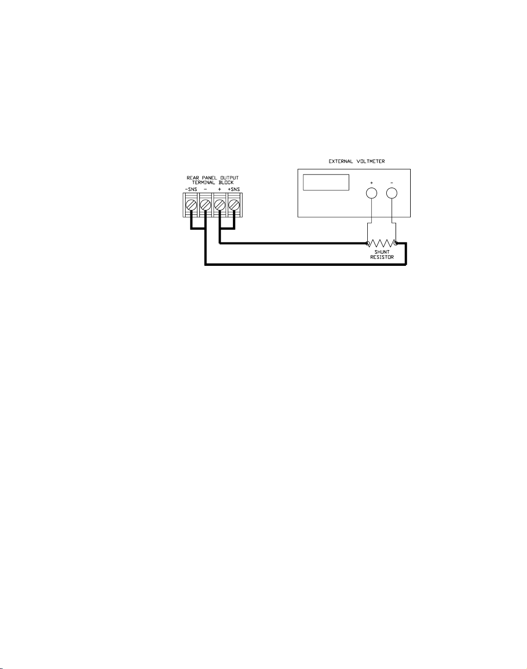
Calibration
Current Mode Calibration
Current Mode Calibration
Current
Calibration
Setup
Current
Program
Calibration
Procedure
1. Disconnect the load from the power supply to be calibrated.
2. Connect a shunt across the supply's output terminals. Ensure the shunt is rated to
handle the maximum voltage and current output from the supply.
3. Connect a voltmeter across the shunt.
Figure 4.2 Current Calibration Setup
1. Connect the shunt and voltmeter to the power supply as shown in Figure 4.2.
2. Activate calibration mode by sending command CMODE ON or CMODE 1 to
the power supply.
3. Send command ILO; VLO to the power supply. Measure and record the output
shown on the external voltmeter.
4. Send command IHI; VHI to the supply Measure and record the output voltage
shown on the external voltmeter.
5. Calculate ILO and IHI from the voltages read from the external voltmeter and
the shunt resistance. I=V/R.
6. Send the command IDATA <ilo>,<ihi> to the power supply. <ilo> and <ihi> are
the current values obtained from sending the ILO and IHI commands to the
power supply. When the power supply is calibrated, the low to high current
program calibration values are stored as constants.
7. Program the supply at various levels using the ISET command to confirm that
the calibration was successful and that linearity is observed. Refer to the current
program accuracy specification in Section 1.
8. Turn off calibration mode by sending the command CMODE OFF or CMODE 0
to the power supply.
56 Operating Manual for RS-232 for XT/HPD Series Power Supply
Page 59

Calibration
Current Mode Calibration
Current
Readback
Calibration
Procedure
1. Connect the current shunt and voltmeter to the power supply as shown in
Figure 4.2.
2. Activate calibration mode by sending command CMODE ON or CMODE 1 to
the power supply.
3. Send command IRLO; VRLO to the power supply. Wait for the supply to settle.
Measure and record the output voltage shown on the external voltmeter. Send
IRLO again.
4. Send command IRHI; VRHI to the supply. Wait for the supply to settle. Measure
and record the output voltage shown on the external voltmeter. Send IRHI again.
5. Calculate IRLO and IRHI from the voltages taken from the external voltmeter
and the shunt resistance. I=V/R.
6. Send the command IRDAT <ilo>,<ihi> to the power supply. <ilo> and <ihi> are
the current values obtained from sending the IRLO and IRHI commands to the
power supply. When the power supply is calibrated, the low to high current
readback calibration values are stored as constants.
7. Program the supply at various levels using the ISET command to confirm that
the calibration was successful and that linearity is observed. Refer to the current
readback accuracy specification in Section 1.
8. Turn off calibration mode by sending the command CMODE OFF or CMODE 0
to the power supply.
Release 1.1 57
Page 60

Calibration
Over Voltage Protection (OVP) Calibration
Over Voltage Protection (OVP) Calibration
We recommend that you perform OVP calibration every six months. Connecting a
digital voltmeter as in “Voltage Calibration Setup” is optional.
1. Disconnect all loads from the power supply.
2. Ensure that jumper J95 on the interface PCB is CLOSED to enable remote OVP
calibration (Jumper J95 is closed at the factory). See Figure 2.3, RS-232
Interface PCB continued., p. 18 for the location on the PCB of jumper J95.
3. Activate calibration mode by sending command CMODE ON or CMODE 1 to
the power supply.
4. Send the command OVCAL to the power supply. The ADDR LED will light
during OVP calibration. Calibration is complete when the ADDR LED turns off.
This may take a few minutes.
5. Use the OVSET, OVSET?, and VSET commands to trip the OVP level,
confirming that the calibration was successful. When you trip the OVP level, the
red OVP LED will light and the voltage will drop to zero. Send the command
RST to clear the OVP condition. Refer to the OVP program accuracy
specification in Section 1.
6. Turn off calibration mode by sending the command CMODE OFF or CMODE 0
to the power supply.
58 Operating Manual for RS-232 for XT/HPD Series Power Supply
Page 61

Page 62

Xantrex Technology Inc.
8999 Nelson Way
Burnaby, British Columbia
Canada V5A 4B5
604 422 8595 Tel
604 421 3056 Fax
800 667 8422 Toll Free North America
prg.info@xantrex.com
www.xantrex.com
TM-RS6H-01XN
PRINTED IN CANADA
 Loading...