


RU-225-35
MODELS INCLUDED
• RU-150
• RU-225
• RU-300
• RU-600
• RU-1000
Wilbur Curtis Co., inC.
Service Manual – RU Series Automatic Urns
Important Safeguards/Symbols
This appliance is designed for commercial use. Any servicing other than cleaning and maintenance
should be performed by an authorized Wilbur Curtis service center.
• Toreducetheriskofreorelectricshock,donotopensideorbottompanel.Therearenouser
serviceable parts inside.
• All repairs should only be performed by authorized service personnel.
• Keep hands and other items away from hot parts of the unit during operation.
• Never clean with scouring powders, bleach or harsh chemicals.
Symbols:
WARNING/CAUTION – To advise about conditions that may result in property damage,
personal injury or death
IMPORTANT – Notes about proper operation
Sanitation requirements
The RU Automatic Urn is factory pre-set and ready to go… right from the carton.
Factory Settings:
WARNING: HOT
LIQUID, Scalding
may occur. Avoid
splashing.
ISO 9001:2008 REGISTERED
WILBUR CURTIS CO., INC.
6913 West Acco Street
Montebello, CA 90640-5403
For the latest information go to
www.wilburcurtis.com
Tel: 800-421-6150
Fax: 323-837-2410
• Brew Temperature = 200°F
• Brew Volume = Set to requirements of coffee liner
System Requirements
•WaterSource:20–100psi(minimumowrateof1gpm)
• Electrical: See attached schematic for standard model or visit www.wilburcurtis.com for your
model.
CAUTION: Please use the setup procedures in this manual before attempting to use the
brewer. Failure to follow the instructions can result in injury or the voiding of the warranty.
See setup procedures on page 2.
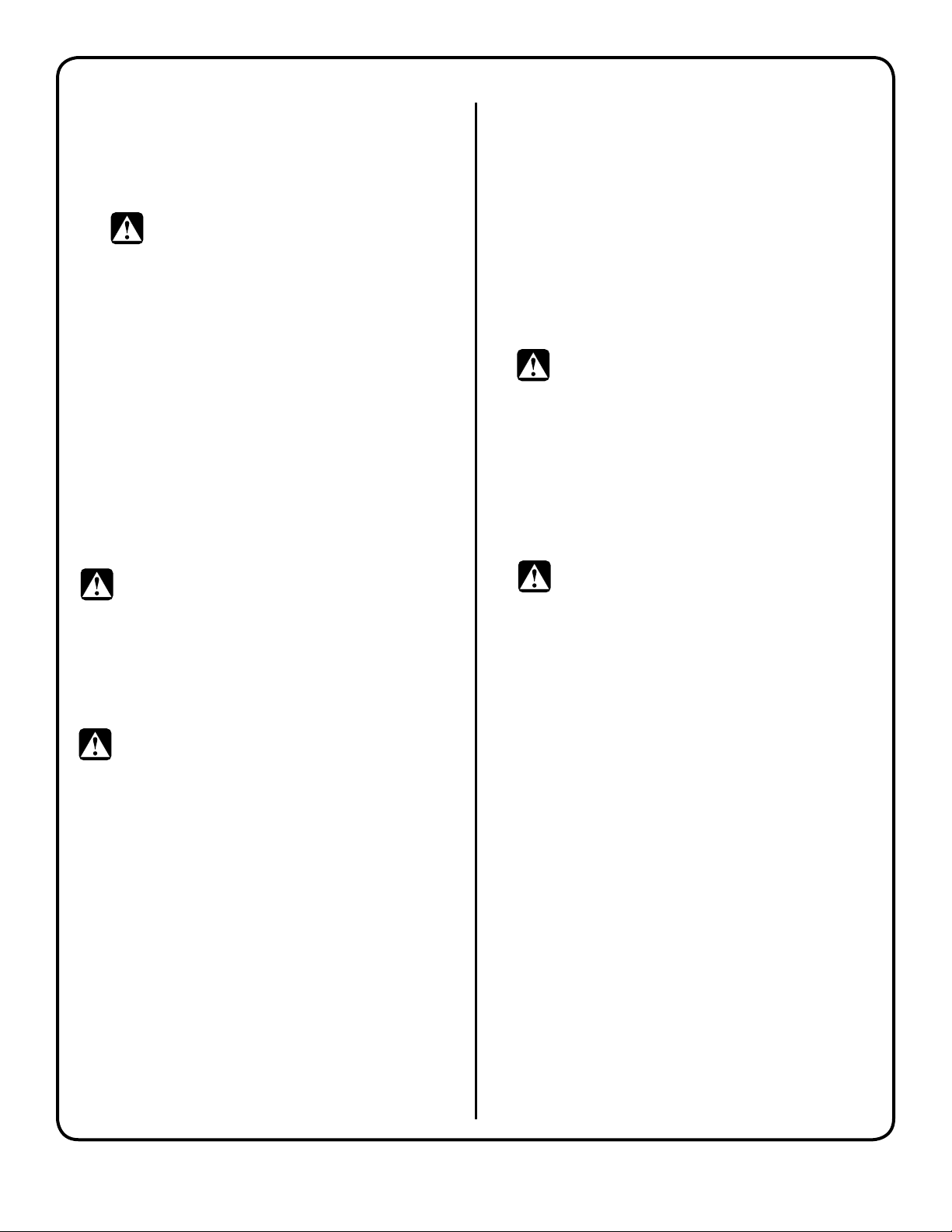
Brewing Instructions
1. Place lter in basket.
Pour coffee into lter.
Place basket into liner.
Technical Support: 800-995-0417 M-F 5:30 a.m. - 4:00 p.m. PT
2. Rotate spray head over
bed of coffee inside
lter.
Email: techsupport@wilburcurtis.com
3. Press BREW button on
control panel to begin
brewing.

INSTALLATION AND OPERATING INSTRUCTIONS
SETUP STEPS
WARNING: DO NOT place this urn closer than six [6] inches from wall. Urn must have adequate cross-ventilation.
NOTE: A water ltration system must be used to help maintain trouble-free operation. Air must
be purged from the cartridge prior to connection to equipment. In areas with extremely hard
water, we recommend the use of a Curtis approved water lter. For our full line of lters, please
log on to www.wilburcurtis.com.
1. Attach adjustable legs, threading them into
the holes beneath the four corners of the urn.
2. Place unit at counter height, on a rm, level
base, near water and power supply connections. Level it left to right and front to back by
rotating the feet on the 4 corners.
WARNING: Use the leveling legs
to level the brewer only. Do not
use them to adjust brewer height. Do not
extend them higher than necessary.
3. Install the water and coffee faucets.
4. Connect water line to inlet tting on valve. All
Curtis automatic urns are equipped with a ¼”
male are tting which must be connected
to the water supply with a ¼” copper tubing
and a ¼” are nut. Water pressure entering brewer is required to be stable and must
provide minimum of 1 gallon per minute. Use
water regulator for constant pressure. Required water pressures, 20 to 100 psi.
CAUTION: Don’t forget to close the
valve once the water jacket has lled.
8. When the water jacket has lled, turn on the
thermostat by turning the dial clockwise to
the desired setting. It will take 50 to 60 minutes for the heating tank to reach operating
temperature. On electric urns, the thermostat
indicator will light at this time.
WARNING: When you hookup an
electric urn, use the proper wire
gauge, plus 25% (see table on page 12).
Never use fuses or breakers larger than
needed.
The body of the urn must be securely
grounded with a separate grounding
conductor and never with the neutral
conductor of a single phase, 3 wire system.
Refer to the wiring diagram included with
each urn for wire gauge.
CAUTION: DO NOT connect this urn
to hot water. The inlet valve is not
rated for hot water.
5. Turn on water valve.
6. Hook-up electrical power to the unit (refer to
schematic for power requirements). If gas or
steam, 120V circuit is required.
7. When power is turned on, water will start owing into the water jacket. To expedite the lling
of the urn, you may use the emergency rell
valve located behind the machine.
2
CARE AND MAINTENANCE OF URN
PREVENTIVE MAINTENANCE
1. Remove the spray head from the urn and
clean it once a week. More often in heavy lime
areas.
WARNING: Switch off the power to the
unit at the circuit breaker. Turn off the
water line running to the urn.
2. Clean the faucet seat cups twice a week and
replace when cracked or leaking.
3. Periodic temperature checks and thermostat
adjustments should be made by authorized
personnel.
CLEANING
To ensure the highest quality coffee, the urn must
be cleaned daily after the last batch of coffee is
used.
Regular cleaning and preventive maintenance is
essential in keeping your coffee urn looking and
working like new.
CAUTION: Do not use cleaning products
containing chemicals that will damage stainless steel, ammonia and bleaches containing
chlorine. Never use abrasives that will scratch the
outside surface of the urn.
DAILY CLEANING INSTRUCTIONS
WARNING: These steps involve working
with very hot water.
1. After all the brewed coffee has been drawn
from the urn, run a brew cycle of fresh water.
Spray the hot water into the liner, then thoroughly brush it out with a long handled brush.
TWICE A WEEK
The coffee urn liner must be scoured twice a
week:
1. Be sure water jacket is full of water and at
brewing temperature.
2. Fill the liner with several gallons of water and
add at least 1½ ounces of coffee urn cleaning
compound. Allow this solution to remain in the
liner approximately 30 minutes. During this
time, the thermostat should be set to BOIL.
WARNING: Very hot water.
3. Scrub the inside of the liner and cover with a
long handled brush.
4. Drain all the urn cleaning solution and rinse
by running several brew cycles with the spray
head centered over the liner, draining the
rinse water between sprays.
5. Thoroughly clean the faucets.
WARNING: Never remove the faucet
when the liner has water or coffee in it.
Switch off the power to the unit at the circuit
breaker. Turn off the water line running to the
urn.
Use a long thin gauge glass brush to clean the
coffee gauge glass. Use the same brush to
clean the tting at the bottom of the liner and
the pipe connecting to the coffee faucet.
6. Leave a gallon or two of fresh water in the
liner. Drain just before brewing coffee.
7. After the unit is clean, turn on the water supply and power to the unit.
2. Drain the water off then repeat step one. Run
another brew cycle. Brush out the liner and
drain. Wipe down the liner with a clean towel.
3. If urn is not going to be used immediately, pour
a gallon or two of fresh water into the liner. Remember to drain off this water before making
another brew.
4. Wash the wire brew baskets with urn cleaner
and rinse thoroughly.
3
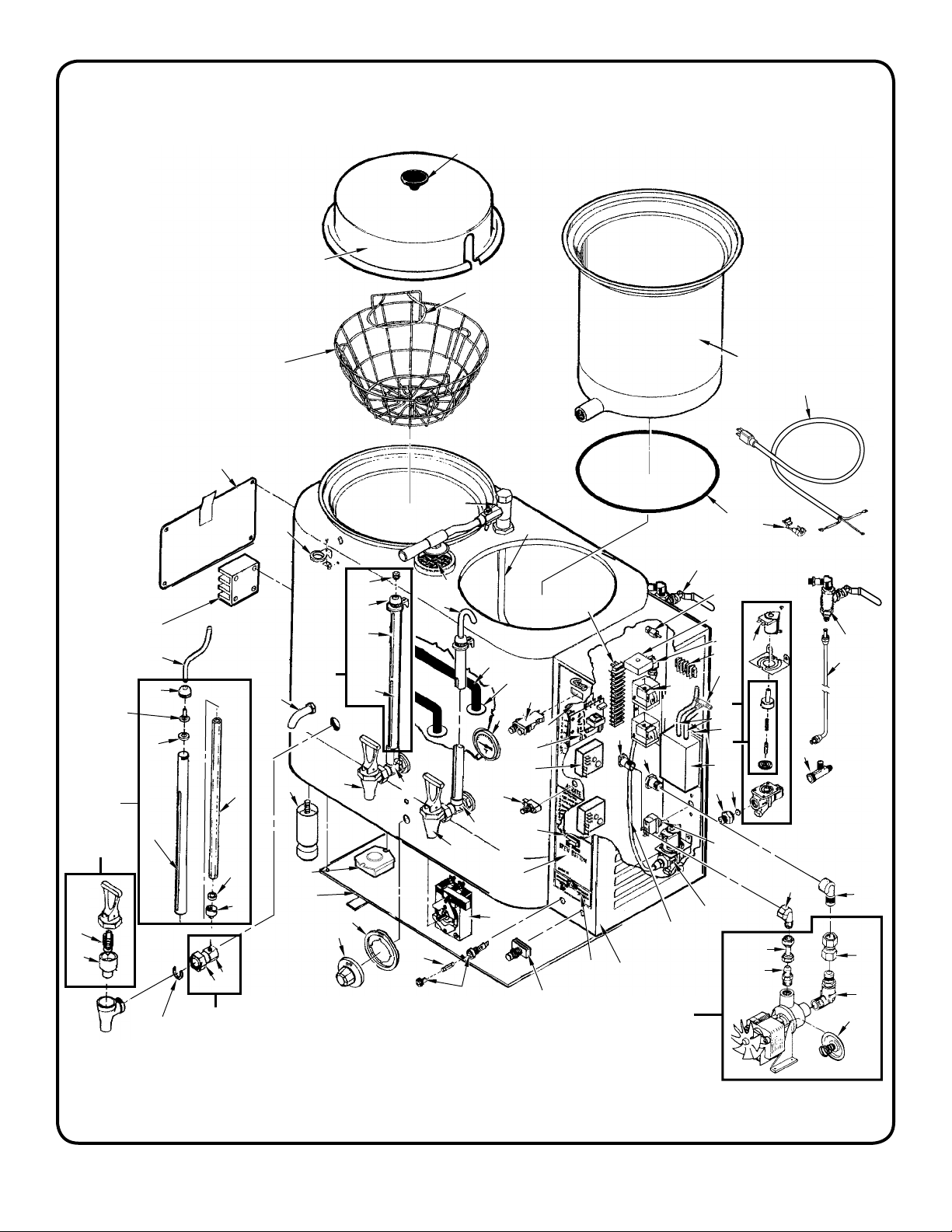
ILLUSTRATED PARTS LIST AUTOMATIC URNS,
RU-150, RU-225, RU-300, RU-600, RU-1000 ELECTRIC
1
2
2A
17
3
3A
3B
85
54
58
60
61
34
35
78
78A
78B
78C
77
76
83
84
48
36
69
61
82*
81
80
80A
80B
80C
79
80D
79A
79B
79C
71
87
70
75
73
72
74
63
63A
63B
63C
62
64
64A
64B
64C
66
15
11
56
35
65
74
67
51
50
53
41
41A
41B
91
86
86A
42
52
43
44
45
46
42
47
47A
47B
47C
27
49
21
21A
21B
21C
34
31
31A
31B
37
37A
33
32
32A
25
4
4A
4B
4C
5
8
39
40
68
11
16
20
12
35
19
13
18
14
15
38
12
29
28
6
7
8
9
9A
10
30
22
23
24
26
*82 NOT INCLUDED WITH GAUGE GLASS ASSEMBLY.
4
INDEX №PART
№
DESCRIPTION
EQUIPMENT USED ON
1 WC-3205 KNOB, LID 1/4-20 FEMALE THRD USE ON WC-5601/2/3 ALL RU URNS
2 WC-5601 LID, LINER ASSY (SC)RU-150/300 RU-150, RU-300
2A WC-5603 LID, LINER ASSY RU225/600/1000 RU-225, RU-600, RU-1000
3 WC-3302 BREW BASKET WIRE W/FLAPS RU-300 RU-150, RU-300
3A WC-3303 BREW BASKET, WIRE W/ FLAPS RU-600 RU-225, RU-600
3B WC-3304 BREW BASKET, WIRE W/ FLAPS RU-1000 RU-1000
4 WC-5700 LINER, 3 GAL RU-150 RU-150
4A WC-5706 LINER, 6 GAL RU-600 RU-225, RU-600
4B WC-5704 LINER, 3 GAL RU-300 RU-300
4C WC-5708 LINER, 10 GAL RU-1000 RU-1000
5 WC-4303 O-RING, LINER RU-150/300 RU-150, RU-300
5A WC-43076 O-RING, LINER, RU’S, 6, 10 GA RU-225, RU-600, RU-1000
6 WC-1200 CORD, 14/3 SJTO 6’ BLK W/PLUG ALL GAS, STEAM & 3Ø RU URNS
7 WC-1408 GRIP, CORD 7/8” OD ALL GAS, STEAM & 3Ø RU URNS
8 WC-806 VLVE, 1/4” BR. BALL ASSY EMERGENCY REFILL RU’S ALL RU URNS
9 WC-53104 TUBE ASSY, 1/4x14.50 ER W/NUTS RU-150/300 RU-150, RU-300
9A WC-53105 TUBE ASSY, 1/4x17.00 ER W/NUTS RU-225/600 RU-225, RU-600
9B WC-53109 TUBE ASSY, 1/4” ER W/NUTS RU-1000 RU-1000
10 WC-2705 TEE, 1/4 X 1/4 FLARE X 3/8 NPT PLATED ALL RU URNS
11 WC-3217 KNOB, ELECTRIC THERMOSTAT RU ALL RU URNS
12 WC-801 VALVE, INLET BRASS .50 GPM 120V 10W RU/WB ALL RU URNS
13 WC-3700 KIT, INLET VAL. REP. USE ON WC-801/801R/885/890/858 ALL RU URNS
14 WC-813 FLOW WASHER, .5GPM .5” S45 ALL RU URNS
15 WC-3220 BEZEL, THERMOSTAT ELECTRIC URN’S ALL RU URNS
16 WC-3011 TERMINAL STRIP, 4-S ALL RU URNS (BEFORE 1/29/13)
17 WC-3305 FLAP, WIRE BASKET RU150/300 (2 REQUIRED) RU-150 & RU-300
18 WC-37166 KIT, AIR PUMP RU’S ALL RU URNS
19 WC-5843 BRACKET, AERATOR PUMP RU ALL RU URNS
20 WC-3600 TEE, CONNECTOR 3/16 POLYPROPYLENE RU-150 & RU-225
21 WC-38570 LABEL, INSTRUCTION PANEL RU150/RU-300 RU-150 & RU-300 (AFTER 1/29/13)
21A WC-38571 LABEL, INSTRUCTION PANEL RU225/RU-600 RU-225 & RU-600 (AFTER 1/29/13)
21B WC-38574 LABEL, INSTRUCTN PANEL RU1000 RU-1000 (AFTER 1/29/13)
22 WC-2405 ELBOW, 1/2 FLARE x 1/2 NPT ALL RU URNS
23 WC-2609 SWIVEL, 1/2” TUBE X 1/2 NPT ALL RU URNS
24 WC-2504 ELBOW, 1/2 NPT X 1/2 NPT ALL RU URNS
25 WC-1037 PUMP, WATER W/FITTINGS 120VAC ALL RU URNS
26 WC-3702 KIT, WATER PUMP SEAL RU’S USE ON WC-1000 ALL RU URNS
27 WC-37165 KIT, THERMOSTAT WC-500A/501A ALL RU URNS
28 WC-2605 CONNECTOR, 3/8 FLARE X 3/8 NPT ALL RU URNS
29 WC-2608 SWIVEL, 3/8 TUBE x 3/8 NPT ALL RU URNS
30 WC-2403 ELBOW, 3/8 FLARE x 3/8 NPT PLATED GEN USE ALL RU URNS
31 WC-5808 DOOR, CONTROL BOX LOUVER, RU-225/600 RU-225, RU-600
31A WC-5807 DOOR, LOUVER ACB RU150/300 RU-150, RU-300
31B WC-5809 DOOR, CONTROL BOX LOUVER RU-1000 RU-1000
32 WC-5322 TUBE ASSY, 1/4x20.00 WI W/NUTS RU-225, RU-600
32A WC-5321 TUBE ASSY, 1/4x17.00 WI W/NUTS RU-150, RU-300
33 WC-2929P FITTING, 1/2 NIPPLE/NUT PLATED ALL RU URNS
34 WC-300 POWER BLOCK 3-STA 175A 600V RU’S ALL RU URNS
35 WC-5307 TUBE, 3/16 ID x 3/32W SILICONE GEN USE ALL RU URNS
36 WC-522 THERMO., HI LIMIT HEATER CONTROL DPST 277V 40A ALL RU URNS
37 WC-402
37A WC-403
1,2
RELAY, HOLDING 120V COIL 10A RU’S ALL RU URNS (BEFORE 1/29/13)
1,2
RELAY HOLDING 120V 3 POLE 6.6A RES.@240V RU-1000 (BEFORE 1/29/13)
38 WC-102 SW, TOG NON-LIT SPST 15A 125/6A 250VAC RESIST. ALL RU URNS
1
OLDER UNITS
2
ITEMS 37 AND 37A, AFTER 1/29/13 SEE ITEMS 45, 45A, 45B
5
INDEX №PART
№
DESCRIPTION
EQUIPMENT USED ON
39 WC-5502-01 KIT, PRB, ASSY WATER LVL W/HEX FITTING, O-RNG & NUT ALL RU URNS
40 WC-405R-101 TIMER, AGITATION 90-260 VAC 30 SEC ALL RU URNS
40A WC-405R TIMER, AG. 120V 50/60HZ W/WIRES & BRKT RU’S ALL RU URNS
41 WC-304
1
TERMINAL STRIP, 14-S(RU1,6) RU-225, RU-600, RU-1000
41A WC-3031 TERMINAL STRIP 12-S RU-150, RU-300
41B WC-3021 TERMINAL STRIP, 6-S(GM,CRA) RU-1000
42 WC-3737 KIT, BREW SWITCH 120V RU’S ALL RU URNS
43 WC-58021 BRACK., WTR LVL. CONT. RU-150/225/300/600/1000 ALL RU URNS
44 WC-608-101K KIT, LIQUID LEVEL CONTROL BOARD RETROFIT ALL RU URNS
45 WC-603-101K-RU KIT, RET. TIMER, BREW SELECTOR 120V RU-300 W/1/2BB SEE NOTE
NOTE: 120V RU URNS BUILT BEFORE JAN. 2013
45A WC-603-101 TIMER, BREW SELECTOR 120V 2-20 MIN GEM-120A/RU’S SEE NOTE
NOTE: 120V RU URNS (EXCEPT RU-1000) BUILT JAN. 2013 AND AFTER
45B WC-603-102 TIMR., BRW. SELT. 120V 2-20 MIN W/FULL & 1/3 BTCH OPT SEE NOTE
NOTE: 120V RU-1000 URNS BUILT BEFORE JAN. 2013
45C WC-622-101K-RU KIT, RETROFIT BREW TIMER FULL & 1/3 BATCH 220V RU SEE NOTE
NOTE: 208/220V RU URNS BUILT BEFORE JAN. 2013
45A WC-622-101 TIMER, BREW SELECTOR 220V 2-20 MIN GEM-120A/RU’S SEE NOTE
NOTE: 208/220V RU URNS (EXCEPT RU-1000) BUILT JAN. 2013 AND AFTER
45B WC-622-102 TIMER, BRW SEL. 220V 2-20 MIN W/FULL & 1/3 BTCH OPT SEE NOTE
NOTE: 208/220V RU-1000 URNS BUILT BEFORE JAN. 2013
46 WC-101 SWITCH, ON/OFF NON-LIT SPST MOMENT. 3/6A 250/120V ALL RU URNS
47 WC-3903 LABEL, INSTRUCT’S PANEL CURTIS RU-600 RU-600
47A WC-3900 LABEL, INSTRUCTION PANEL RU150 RU-150
47B WC-3901 LABEL, INSTRUCTION PANEL RU225 RU-225
47C WC-3902 LABEL, INSTRUCT’S PANEL CURTIS RU-300 RU-300
47D WC-3904 LABEL, INSTRUCT’S PANEL CURTIS RU1000 RU-1000
48 WC-3528 LEG, 4” ADJUSTABLE 3/8-16 THRD ITALIAN STYLE ALL RU URNS
49 WC-100 SW, RES-STOP N.C.NON-LIT SP MOMENT 10/15A 250/120V ALL RU URNS
50 WC-1501 FUSE, HOLDER ASSY W/5A FUSE ALL RU URNS
51 WC-1500 FUSE, 5 AMP ALL RU URNS
52 WC-511 THERMOMETER, DIAL RU’S ALL RU URNS
53 WC-5313 TUBE, SPRAYARM ASSY W/NUTS RU-300 RU-300, RU-150
53A WC-5314 TUBE, SPRAYARM ASSY W/NUTS RU-600 RU-225, RU-600
53B WC-5315 TUBE, SPRAYARM ASSY W/NUTS RU-1000 RU-1000
54 REFER TO VALVE CORE & SPRAY ARM ON PAGE 8
56 WC-5800 RING, STEAM ALL RU URNS
58 WC-2007 BRACKET, GAUGE GLASS GEM-3 ALL RU URNS
60 WC-2003 CAP, PLUG VENTED 44 ALL RU URNS
61 WC-2002 CAP, SHIELD W/CLEAN OUT ALL RU URNS
62 WC-2030 GLASS, GAUGE 13” RU-225, RU-600
63 WC-2108 GAUGE GLASS ASSEMBLY 13” USE ON RU-225 RU-225, RU-600
63A WC-2104 GAUGE GLASS ASSEMBLY 10” RU-150
63B WC-2105 GAUGE GLASS, ASSY 11” USE ON RU-150/300 RU-150, RU-300
63C WC-2113 GAUGE GLASS, ASSY 19” RU-1000
64 WC-2017 SHIELD, GAUGE GLASS 13” RU-225, RU-600
64A WC-2104 SHIELD, GAUGE GLASS 10” RU-150
64B WC-2014 SHIELD, 11” GAUGE GLASS RU-300
64C WC-2022 SHIELD, 19” GAUGE GLASS 1/8 NPT RU-1000
65 WC-1900 VALVE, GAUGE SHIELD SHUT-OFF 1/8 NPT ALL RU URNS
66 WC-1800L FAUCET, “S” SERIES LOCKING 1-1/32-14 UNS ALL RU URNS
70 WC-1805 SEAT CUP, “S” FAU USE ON WC-1800/B/LB/D/DL/L/WC-1803 ALL RU URNS
71 WC-3705 KIT, FAUCET S SERIES NONLOCK USE ON WC-1800 ALL RU URNS
72 WC-1906 C’ RING .917 X .760 X .090 TT-3 TC’S ALL RU URNS
1
OLDER UNITS
BEFORE
1/29/13
6
 Loading...