


MODELS INCLUDED
•RU-150
•RU-225
•RU-300
•RU-600
•RU-1000
CAUTION: Please use this setup procedure before attempting to use
this brewer. Failure to follow the instructions can result in injury or the voiding of the warranty.
WARNING: DO NOT place this urn closer than six [6] inches from wall. Urn must have adequate
cross-ventilation.
CAUTION: DO NOT connect this urn to hot water. The inlet valve is
not rated for hot water.
 WARNING When you hookup an electric urn, use the proper wire gauge, plus 25%. Never use fuses
or breakers larger than needed. The body of the urn must be securely grounded with a separate grounding conductor and never with the neutral conductor of a single phase, 3 wire system.
Refer to the wiring diagram included with each urn for wire gauge.
ISO 9001:2008 REGISTERED
WILBUR CURTIS CO., INC.
6913 WestAcco Street
Montebello, CA90640-5403 For the latest information go to www.wilburcurtis.com
Tel: 800-421-6150
Fax: 323-837-2410
Wilbur Curtis Company, Inc.
Service Manual – RU SeriesAutomatic Urns
Important Safeguards/Symbols
This equipment is designed for commercial use.Any servicing other than cleaning and routine maintenance should be performed by an authorized Wilbur Curtis Company Service Technician.
•DO NOT immerse the unit in water or any other liquid
•To reduce the risk of fire or electric shock, DO NOT open service panels. There are no user serviceable parts inside.
•Keep hands and other items away from hot areas of the unit during operation.
•Never clean with scouring powders or harsh chemicals.
Symbols
WARNINGS – To help avoid personal injury
Important Notes/Cautions – from the factory
Sanitation Requirements
The RUAutomatic Urn is Factory Pre-Set and Ready to Go… Right from the Box.
Factory Settings:
•Brew Temperature = 200°F • Brew Volume = Set to requirements of coffee liner. System Requirements
•Water Source: 20 – 100PSI (Min Flow Rate of 1 GPM)
•Electrical: See attached schematic for standard model or visit www.wilburcurtis.com for your model.
•HEAT SUPPLY: Read the serial tag to determine the energy source (electric, gas, steam).
SETUP STEPS
1.Place unit at counter height. on a firm, level base, in such a way that it can be connected to water and power supply.
2.Install the water and coffee faucet.
3.Connect water line to inlet fitting on valve. It is recommended that some type of water mineral reducing filter be used in the water line before entering the unit. Water pressure entering brewer is required to be stable and must provide minimum of 1 gallon per minute. Use water regulator for constant pressure. Required water pressures, 20 to 100 psi. Turn on water valve.
4.If setting up a gas urn, connect gas line with 3/8” O.D. flex tube from urn to gas valve in the facility. Check for leaks.
5.Hook-up electrical power to the unit (refer to schematic for power requirements). If gas or steam, 120V circuit is required.
6.When power is turned on, water will start flowing into the water jacket. You may increase the speed of the filling by using the emergency refill valve.
7.When the water jacket has filled, turn on the thermostat by turning the dial clockwise to the desired setting. It will take 50 to 60 minutes for the heating tank to reach operating temperature. On electric urns, the thermostat indicator will light at this time.
NSF International requires the following:
1.Aquick disconnect or additional coiled tubing (at least 2x the depth of the unit) so the unit can be moved for cleaning.
2.This equipment is to be installed with adequate backflow protection to comply with applicable federal, state and local codes.
3.Water pipe connections and fixtures directly connected to a portable water supply shall be sized, installed and maintained in accordance with federal, state, and local codes.
BREWING INSTRUCTIONS
WARNING HOT LIQUID, Scalding may occur. Avoid splashing.
1. Place filter in basket. Pour coffee into |
2. Rotate sprayhead over bed of coffee |
3. Press the BREW button on control |
filter. Place basket into liner. |
inside filter. |
panel to begin brewing. |
For the latest specifications and information go to www.wilburcurtis.com
Technical Support: 1-800-995-0417 M-F 5:30am-4:00pm PT
Email: techsupport@wilburcurtis.com
ELECTRIC THERMOSTAT ADJUSTMENT
On electric urns, thermostats are set at the factory to cut off at 200ºF. We do not recommend changing this. If necessary, adjustment is as follows:
1.Rotate the thermostat knob to the right to the BOILposition. Remove the knob by pulling off from the stem.
2.Locate the tiny adjustment screw, inside the stem (see figure 1). Using a small screwdriver, adjust the temperature up or down:
a.By turning the screw ¼ turn to the left will increase the temperature about 20°F.
b.Turning ¼ to the right will decrease the temperature by 20°F.
c.To set the thermostat precisely at 200°F, insert a thermometer probe into the water jacket through the steam hole (just under the sprayhead). Turn the screw ½ turn to the left. When the thermometer reaches 200°F, slowly turn the adjustment screw to the right until the pilot light turns off.
GAS URN INSTALLATION
The urn must be away from wall no less than 6” and must have plenty of cross ventilation.
The water supply connection is the same in all RU models.All that is needed is 1/4” copper tubing with a 1/4” flare nut and some sort of water filter in the line before water enters the unit. Once the water connection is complete, open the water line, then plug in the power cord into an 115V outlet. To facilitate the filling of the water jacket, you can open the
emergency refill faucet (red knob) behind the unit, to increase the speed of filling the urn. Water must be above the base of the center gauge glass before turning on the heat.
GAS CONNECTION
All RU automatic urns are supplied with a 3/8” pressure connector at the end of the gas valve. This valve is connected to the thermostat. Use 3/8” O.D. stainless steel flex tubing to make the connection from the urn to the gas valve in your facility. When the connections are complete, turn the gas on. Check the line for leaks.
PROCEDURE FOR LIGHTING OR RELIGHTING PILOT
1.Remove the pilot control cover on the right side of the thermostat cover (held in place by four screws).
2.Turn the pilot dial to the OFF position and thermostat dial to the lowest temperature position.
3.Allow sufficient time for any gas that may still be in the burner compartment to dissipate.
4.Push in the pilot dial (the dial has a slight inward travel) and rotate it to the PILOT position. On older units, there is a separate red SET button that must be pushed in to allow the dial to turn.
5.Continue pressing in the dial while lighting the pilot burner. The pilot is located inside the burner compartment, between the main burners.
6.Once lit, allow the flame to burn for approximately 30 seconds before releasing pilot dial. If the pilot flame does not remain lit, repeat the operation, allowing for a longer period before releasing the pilot dial.
7.Turn the pilot dial to the ON position. Turn the thermostat dial to the desired position. The main burner will then ignite.
MAIN BURNER ADJUSTMENT
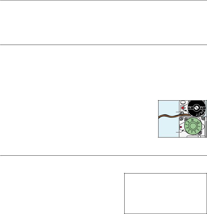
To adjust the main burner flame, turn the thermostat dial to 6½ for 195ºF or 7 for 200ºF; see figure 1. For older units (made before serial number 12327781), turn the screw under the gas cock handle in either direction to regulate the flow of gas to the main burner.
PILOT
DIAL
THERMOSTAT
DIAL
Fig 1. Dial on the gas thermostat set at 6½.
TO RE-CALIBRATE THE THERMOSTAT
The Unitrol thermostat is built to the most exacting standards and is a precision instrument which should never need re-calibration. However because of tampering, misuse or other reason, if the thermostat is found to be more than 10º from normal, a re-calibration may be performed by a qualified service technician. The following are the steps for this procedure:
1.Turn the thermostat to OFF to allow the unit to cool down.
2.When the water temperature is room temperature, turn the thermostat dial until the main burner ignites.
3.Slowly, turn the thermostat dial counterclockwise until the flame on the burner goes out.
4.Place a thermometer into the water jacket to determine the temperature of the water.
5.Pull off the thermostat dial and lift off the outside cover.
6.Turn the temperature stop to correspond to the actual water temperature. Mark the location of the stop for reference.
7.Turn the stop slowly until the control snaps off. Holding the stop to prevent rotation, carefully loosen the stop adjustment nut (see figure 2).
8.Taking care not to move the temperature adjusting screw, turn the stop until it lines up with the tick mark (see step 6).
9.Hold the stop in place and tighten the stop adjustment nut.
10.Recheck the OFF temperature.
11.Replace the outside cover and thermostat dial.
THERMOCOUPLE CONNECTION
Poor contact between the thermocouple lead and the magnet assembly may cause the valve to be inoperative even when the pilot is in proper adjustment and position. If this is the problem, clean and tighten the contact points. Remove the thermocouple and carefully clean the parts that make contact with the magnet assembly.
PROCEDURE FORADJUSTING PILOT
1.Remove pilot adjustment cap.Adjust pilot key, allowing flame to completely envelop the end ( ⅛”) of the thermocouple.
2.Adjust pilot burner air shutter (if provided) to obtain a soft blue flame.
2
 Loading...