


YSF379LEKB0
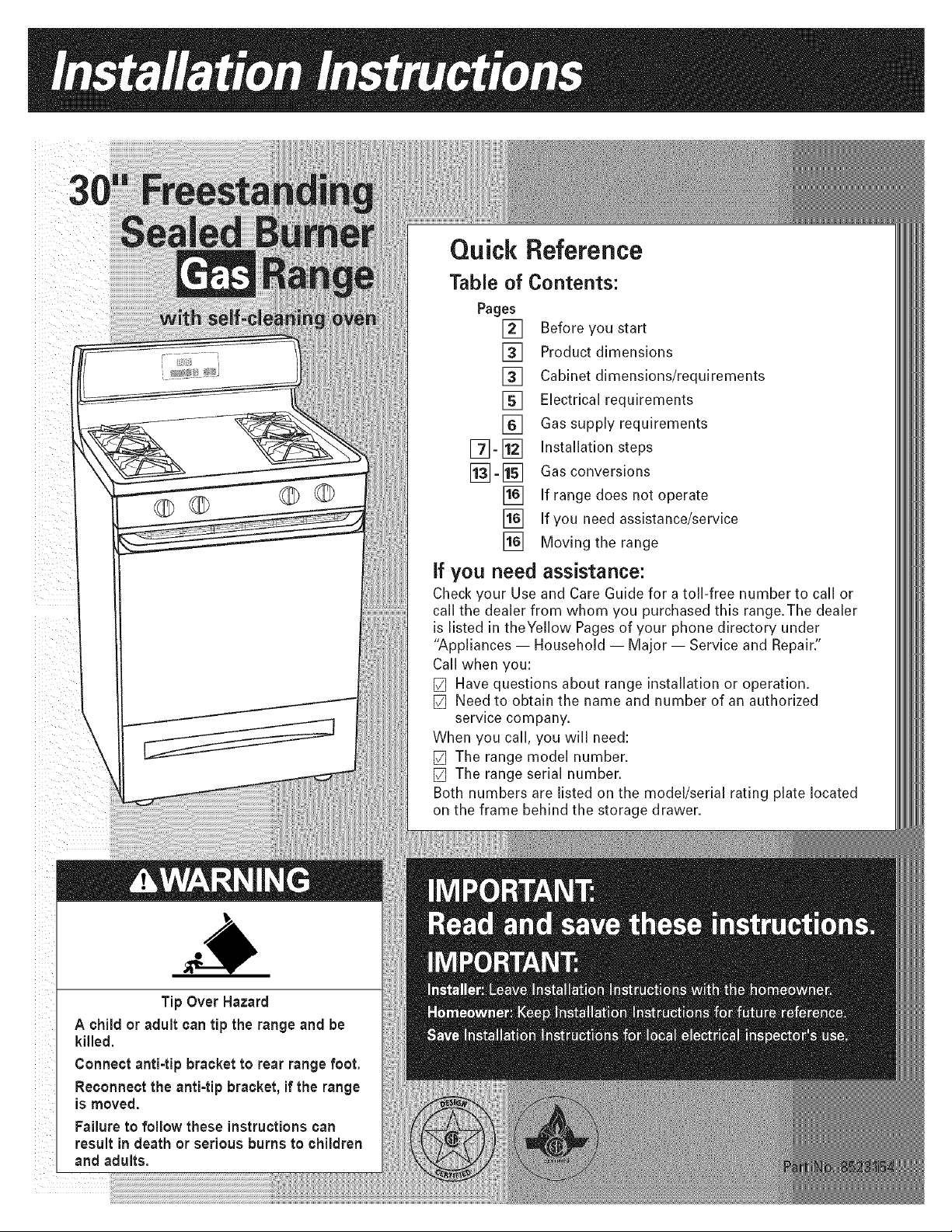
Tip Over Hazard
A child or adult can tip the range and be
killed.
Connect anti-tip bracket to rear range foot.
Reconnect the anti=tipbracket, if the range
is moved.
Failure to follow these instructions can
result in death or serious burns to children
and adults.
Quick Reference
Table of
Pages
[]
[]
[]
[]
[]
[]-[]
[]
[]
[]
if you need
Contents:
Before you start
Product dimensions
Cabinet dimensions/requirements
Electrical requirements
Gas supply requirements
Installation steps
Gas conversions
If range does not operate
If you need assistance/service
Moving the range
assistance:
Check your Use and Care Guide for a toll-free number to call or
call the dealer from whom you purchased this range.The dealer
is listed in theYellow Pages of your phone directory under
"Appliances -- Household -- Major -- Service and Repair."
Call when you:
[] Have questions about range installation or operation.
[] Need to obtain the name and number of an authorized
service company.
When you call, you will need:
[] The range model number.
[] The range serial number.
Both numbers are listed on the model/serial rating plate located
on the frame behind the storage drawer.
Yoursafetyand the safety of others are veryimportant.
Wehaveprovided many important safety messagesin this
manual and onyour appliance.Always read andobey all safety
messages.
This is the safety alert symbol.
This symbol alerts you to potential hazardsthat can kill
or hurt you and others.
All safety messageswill follow the safety alertsymbol and
either the word "DANGER"or "WARNING". Thesewords mean:
Youcan bekilled or seriously injuredif youdon't
immediately follow instructions.
Youcan bekilled or seriously injuredif youdon't follow
instructions.
All safety messageswill tell you whatthe potential hazardis,
tell you how to reducethe chanceof injury, and tell you what
can happenif the instructions arenot followed.
WARNING: If the information in this
manual is not followed exactly, a fire or
explosion may result causing property
damage, personal injury or death.
m Do not store or use gasoline or other
flammable vapors and liquids in the
vicinity of this or any other appliance.
WHAT TO DO IF YOU SMELL GAS
, Do not try to light any appliance.
• Do not touch any electrical switch.
• Do not use any phone in your building.
• Immediately call your gas supplier
from a neighbor's phone. Follow the
gas supplier's instructions.
• If you cannot reach your gas supplier,
call the fire department.
= Installation and service must be per=
formed by a qualified installer, service
agency or the gas supplier.
important: Observe all governing codes and
ordinances.
Do not obstruct flow of combustion and ventilation air.
This installation must conform with all local codes and
ordinances. In the absence of local codes, installation
must conform with American National Standard,
National Fuel Gas Code ANSI Z223.1 -- latest edition*
or CAN/CGA -- B149 -- latest edition* installation
codes.
It is the customer's responsibility:
• To contact a qualified electrical installer.
•To assure that the electrical installation is adequate
and in conformance with National Electrical Code,
ANSI/NFPA 70 -- latest edition**, or CSA Standard
C22.1, Canadian Electrical Code, Part 1 -- latest
edition*, and all codes and ordinances.
Cabinet opening dimensions shown must be used. Given
dimensions are minimum clearances.
When installing a range under existing cabinets and the
installation does not meet the minimum cabinet clearances,
install a range hood above the cooktop to avoid burn
hazards.
Proper installation is your responsibility. A qualified
technician must install this range. Make sure you have
everything necessary for correct installation. It is the
installer's responsibility to comply with installation
clearances specified on the gas information label.The gas
information label and model/serial rating plate are located
on the frame behind the storage drawer.
Copies of the standards listed may be obtained from:
* CSA International
8501 East Pleasant Valley Rd.
Cleveland, Ohio 44131-5575
** National Fire Protection Association
One Batterymarch Park
Quincy, Massachusetts 02269
Page 2
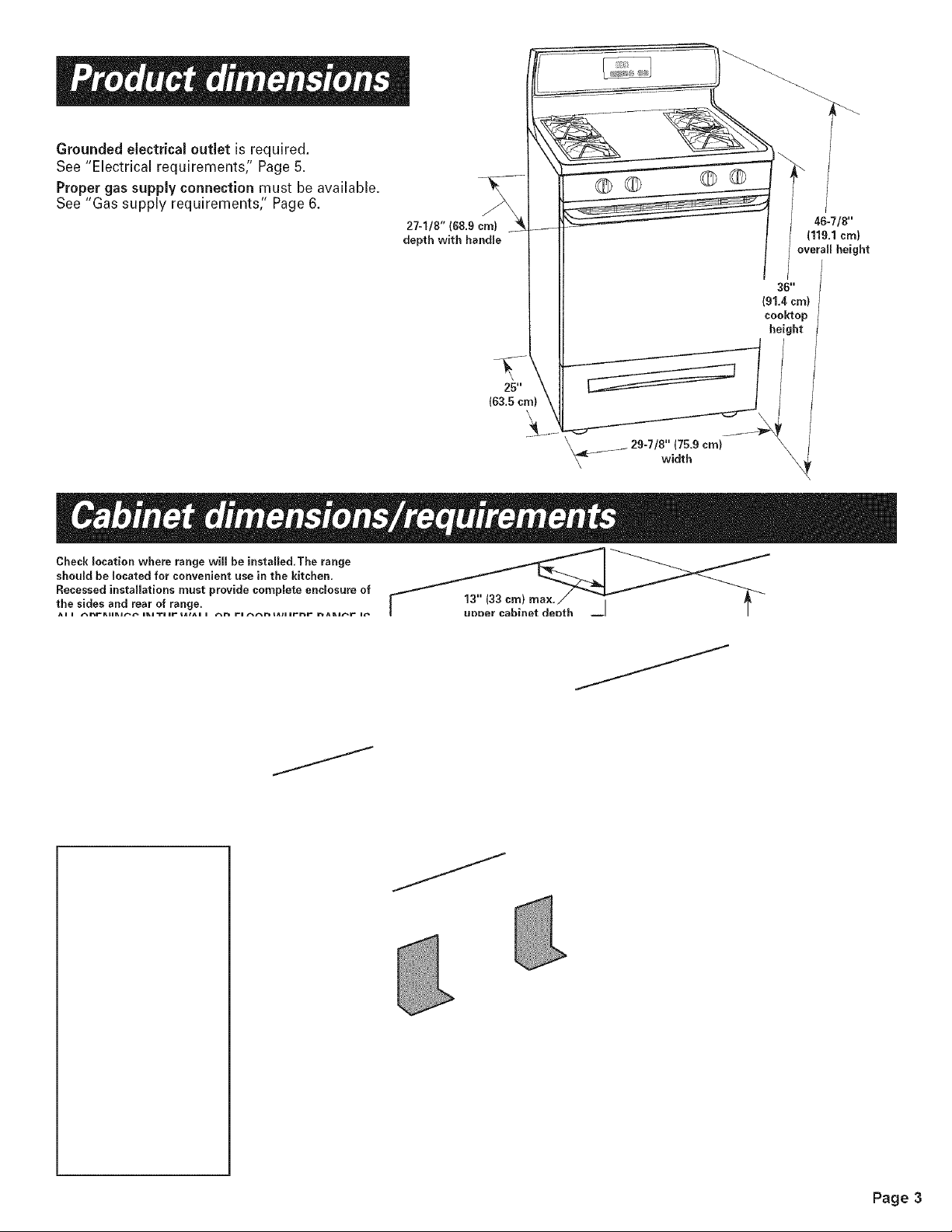
Groundedelectricaloutletis required.
See "Electrical requirements;' Page 5.
Proper gas supply connection must be available.
See "Gas supply requirements" Page 6.
J
27-1/8" (68.9 cm)
depth with handle
25"
(63,5 cm)
\
OQ ©O
,_ .......... 29-7/8" (75.9 cm)
width
36"
(91.4 cm)
cooktep
height
Check _ocation where range will be installed, The range _......_t_ I _ _ -
should be located for convenient use in the kitchen,
Recessed installations must provide cempEete enclosure of
the sides and rear of range, unn__r cabinet de_nth I
Ae e _rRBeRJ_ eRJTeer t_l^e e _ re _taleernr _ARJ_r e_
Page 3

Mobile home installation
The installationof this range must conform to the Manufactured
Home Construction and Safety Standards,Title 24 CFR,Part
3280 (formerly the Federal Standard for Mobile Home
construction and Safety,Title 24, HUD, Part280);or when such
standard is not applicable, the Standard for Manufactured
Homes Installations (Manufactured Home Sites,Communities
and Setups),ANSIA225.1/NFPA501A*, or with local codes.
In Canada, the installationof this range must conform with
the current standards CAN/CSA-Z240 -- latest edition**, or
with local codes.
When this range is installedin a mobile home, it must be
secured to the floor during transit. Any method of securing
the range is adequate as long as itconforms to the standards
listed above.
Copies of the standards listed may be obtained from:
* National Fire Protection Association
One Batterymarch Park
Quincy, Massachusetts 02289
_ CSA International
8501 East Pleasant Valley Rd.
Cleveland, Ohio 44131-5575
floor-mounted
anti-tip bracket
O O
2 plastic
anchors
Not shown: 2 screws_ ___• literature pack (#10 x 1-1/2"}
• orifice spuds
Bracket must be securely mounted to sub-floor.Thickness
of flooring may require longer screws to anchor bracket to
sub-floor. Longer screws are available from your local
hardware store.
e t-blade screwdriver
J screwdriver
wood floor:
1/8" drill bit [_ tape measure
concrete/ceramicfloors: I 2/orruler
3/16" carbide-tipped masonry \ Z_L'L_'__'_'L_._,._
drill bit (Hammer may be need-
ed for anchors.}
channel lock
_ pliers
and3,8....
putty knife
combination stainless
wrenches steel/glass
mirror
pipe
wrench
safety glasses
nd or electric drill
Materials required:
• gas line shutoff valve
• 1/2" male pipe thread nipple for connection to pressure regulator
• L.R gas-resistant pipe-joint compound
AGA or CSA design-certified flexible metal appliance connector (4-5 feet}
(1.2-1.5 m} or rigid gas supply line as needed
• insulated pad or 1/4" (6 ram} plywood if range is installed
over carpeting
Page 4

ElectricalShockHazard
Pluginto a grounded 3-prong outlet.
Do not remove ground prong.
Do not use an adapter.
Failure to follow these instructions can result in
death, fire, or electrical shock.
Recommended
ground method
For personal safety, this range isequipped with a power
supply cord having a 3-prong ground plug.To minimize
possible shock hazard, the cord must be plugged into a
mating 3-prong, ground-type outlet, grounded in accordance
with the National Electrical Code, ANSI/NFPA 70 -- latest
edition* or CSA Standard C22.1, Canadian Electrical Code,
Part 1,- latest edition** and all local codes and ordinances.
If a mating outlet is not available, it is the personal
responsibility and obligation of the customer to have a
properly polarized and grounded, 3-prong outlet installed by
a qualified electrician.
if codes permit and a separate ground wire is used, it is
recommended that a qualified electrician determine that the
ground path isadequate and that the outlet is correctly
polarized.
Do Not ground to a gas pipe.
Check with a qualified electrician if you are not sure range is
properly grounded.
A 120-volt, 60-Hz, AC-only, 10-ampere, fused electrical
supply is required. A time-delay fuse or circuit breaker is
recommended. It is recommended that a separate circuit
serving only this appliance be provided.
Electronic ignition systems operate within wide voltage
limits, but proper grounding and polarity are necessary.
In addition to checking that the outlet iscorrectly grounded,
the outlet must be checked by a qualified electrician to see if
it is wired with correct polarity.
Important:This range isequipped with an electronic ignition
system that will not operate if plugged into an outlet that is
not properly polarized.
Copies of the standards listed may be obtained from:
* National Fire Protection Association
One Batterymerch Park
Quincy, Massachusetts, 02269
_ CSA International
8501 East Pleasant Valley Rd,
Cleveland, Ohio 44131-5575
3-prong ground
plug _
d
power supply
cord
3-prong properly polarized
ground-type outlet
A wiring diagram is includedon the back of the range.
See "Cabinet dimensions/requirements" Page 3, for
recommended location of electrical outlet.
Page 5

ExplosionHazard
Usea new AGAor CSA approved gas supply line.
Install a shut=offvalve.
Securely tighten all gas connections.
If connected to LP,have a qualified personmake sure
gas pressure does not exceed 14" water column.
Examples of a qualified person include licensed heating
personnel, authorized gas company personnel, and
authorized service personnel.
Failure to do so can result in death,explosion, or fire.
Observe allgoverning codesand ordinances.
This installation must conform with localcodes and
ordinances. In the absence of local codes, installations must
conform with American National Standard, National Fuel
Gas Code ANSI Z223.1 -- latest edition or CAN/CGA-B149 --
latest edition* installation codes.
Input ratings shown on the model/serial rating plate are for
elevations up to 2,000 feet (610 m). For assistance when
installingthe range at higher elevations, contact your local
service company.
Type of gas: This range is design-certified by CSA
International for use with Natural gas or, after proper
conversion, for use with L. P.gas. This range is factory set
for use with Natural gas. Gas conversion instructionsare
provided on pages 13-15. The model/serial rating plate
located on the frame behind the storage drawer or broiler
door has information on the type of gas that can be used. If
the type of gas listed does not agree with the type of gas
available, check with the local gas supplier. Conversion
must be done by a qualified service technician.
Gas supply line: Provide a gas supply line of 3/4" rigid pipe
to the range location. With L.R gas, piping or tubing sizecan
be 1/2" minimum. A smaller size pipe on longer runs may
result in insufficientgas supply. Usually, LR gas suppliers
determine the size and materials used inthe system.
Pipe-joint compounds made for use with L.R gas must be
used on pipe threads only.
Flexible metal appliance connector: If local codes permit, a
newAGA or CSA design-certified, 1/2" or 3/4" I.D.,
flexible metal appliance connector isrecommended for
connecting range to the gas supply line. A 1/2" male pipe
thread nipple is needed for connection to pressure regulator
female pipe threads. Do Not kink or damage the flexible
metal tubing when moving the range.
Rigid pipe _, , ,==
connection: I I! - -
Requires a _
combination of pipe
fittings to obtain an in-lineconnection to the range. _
All strains must be removed from the supply and 111'II
fuel lines so range will be level and in line. I_I
manual shutoff valve __
"open"position .___
Shutoff valve:The supply line must be equipped with a man-
ual shutoff valve.This valve should be located in the same
room asthe range and should be in a location that allows
ease of opening and closing.The valve is for turning on or
shutting off gas to the range. Do Not block access to shutoff
valve.
Pressure regulator:The gas pressure regulator supplied with
this range must be used.The inlet pressure to the regulator
should be as follows for proper operation:
NATURAL GAS:
Minimum pressure: 5 inchesW.C.
Maximum pressure: 14 inchesW.C.
L.P.GAS:
Minimum pressure: 11inchesW.C.
Maximum pressure: 14 inchesW.C.
Contact local gas supplier if you are not sure about the inlet
pressure.
Line pressure testing above 1/2 psi gauge
(14"WCP)--The range and its individual manual shutoff
valve must be disconnected from the gas supply piping
system during any pressure testing of that system at test
pressures greater than 1/2 psig (3.5 kPa).
Line pressure testing at 1/2 psi gauge
(14"WCP} or lower--The range must be isolatedfrom the
gas supply piping system by closing its individual manual
shutoff valve during any pressure testing of that system at
test pressures equal to or less than 1/2 psig (3.5 kPa).
Copies of the standards listed may be obtained from:
* CSA international
8501 East Pleasant Valley Rd.
Cleveland, Ohio 44131-5575
Page 6
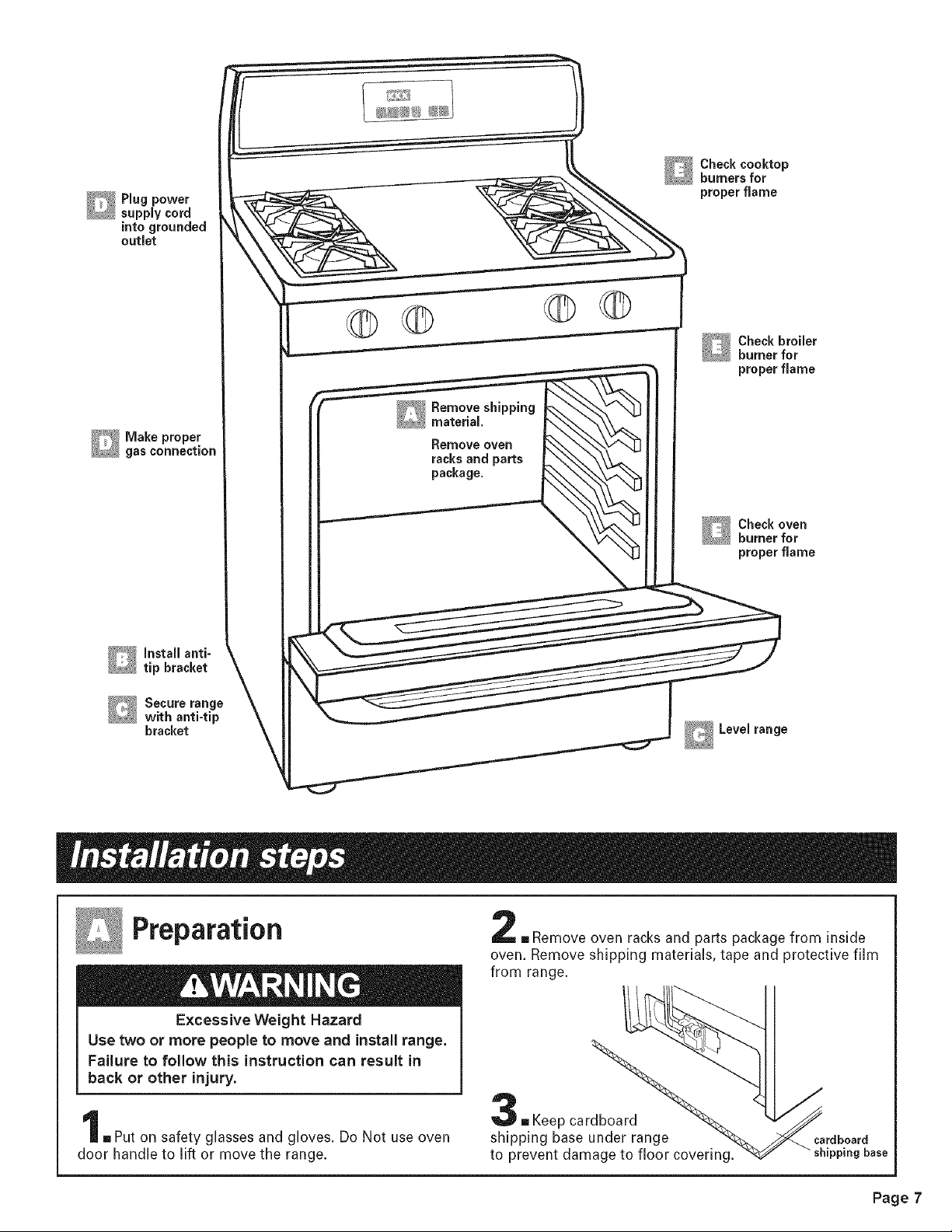
into grounded
outlet
__' Make proper
_gas connection
Install anti-
tip bracket
_ ecure range
with anti-tip
bracket
©
©
Remove oven
racksand parts
package.
® Check cooktop
burnersfor
proper flame
Levelrange
Preparation
Excessive Weight Hazard
Use two or more people to move and install range.
Failure to follow this instruction can result in
back or other injury.
-, Put on safety glasses and gloves. Do Not use oven
door handle to lift or move the range.
[] Remove oven racks and parts package from inside
oven. Remove shipping materials, tape and protective film
from range.
,, Keep cardboard
shipping base under range
to prevent damage to floor covering.
cardboard
shipping base
Page 7
Anti-tip bracket installation
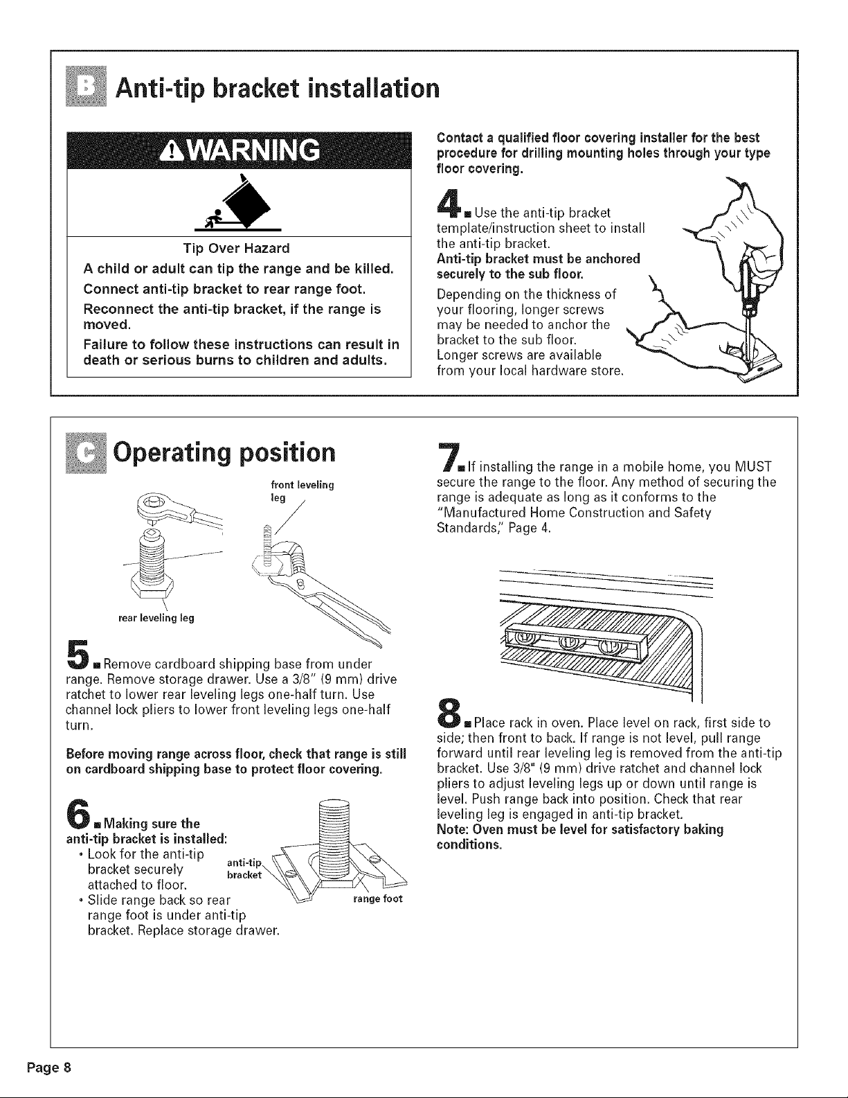
Tip Over Hazard
A child or adult can tip the range and be killed.
Connect anti-tip bracket to rear range foot.
Reconnect the anti=tip bracket, if the range is
moved.
Failure to follow these instructions can result in
death or serious burns to children and adults.
Contact a qualified floor covering installerfor the best
procedure for drilling mounting holes through your type
floor covering.
m Use the anti-tip bracket
template/instruction sheet to install
the anti-tip bracket.
Anti-tip bracket must be anchored
securely to the sub floor.
Depending on the thickness of
your flooring, longer screws
may be needed to anchor the
bracket to the sub floor.
Longer screws are available
from your local hardware store.
Operating position
front leveling
leg /
rear leveling leg
- Remove cardboard shipping base from under
range. Remove storage drawer. Use a 3/8" (9 mm) drive
ratchet to lower rear leveling legs one-half turn. Use
channel lock pliers to lower front leveling legs one-half
turn.
Before moving range across floor, checkthat range is still
on cardboard shipping baseto protect floor covering.
. Making sure the \___
anti-tip bracket is installed:
. Look for the anti-tip anti-tip
bracket securely bracket
attached to floor. __
• Slide range back so rear _ range foot
range foot is under anti-tip
bracket. Replace storage drawer.
=If installingthe range in a mobile home, you MUST
secure the range to the floor. Any method of securing the
range is adequate as long as itconforms to the
"Manufactured Home Construction and Safety
Standards:' Page 4.
= Place rack in oven. Place level on rack, first side to
side; then front to back. If range is not level, pull range
forward until rear leveling leg is removed from the anti-tip
bracket. Use 3/8" (9 mm) drive ratchet and channel lock
pliers to adjust leveling legs up or down until range is
level. Push range back into position. Check that rear
leveling leg is engaged in anti-tip bracket.
Note: Oven must be level for satisfactory baking
conditions.
Page 8
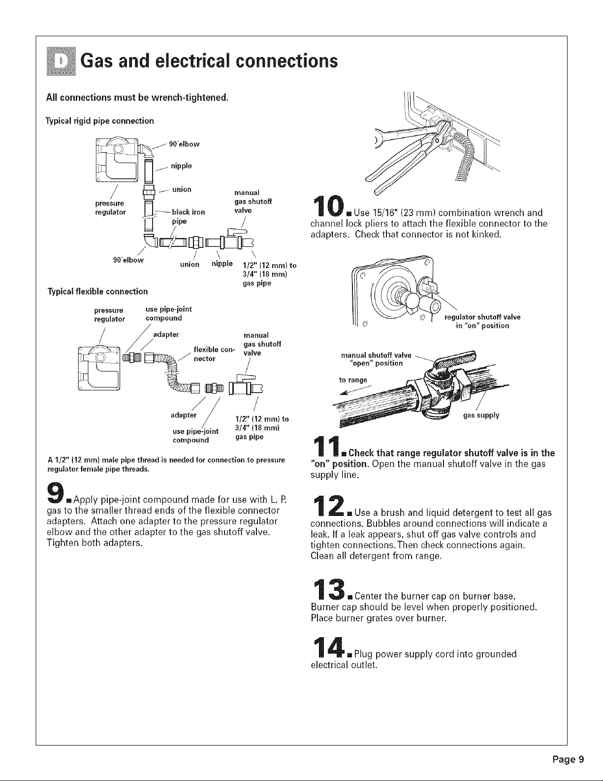
Gas and electrical connections
All connections must be wrench-tightened.
Typical rigid pipe connection
/90°elbow
_ nipple
/ _] _ union
pressure
regulator
pipe
manual
gas shutoff
valve
/
90°elbow
Typicalflexible connection
union nipple
\
1/2" (12 ram) to
3/4" (18 mm)
gas pipe
pressure
regulator
use pipe-joint
compound
adapter manual
gas shutoff
flexible con- valve
hector
//
sdspt / l/z, mm to
/ 3/4" (18 mm)
use pipe-joint
compound gas pipe
A I/2" (12 ram) male pipe thread is needed for connection to pressure
regulator female pipe threads.
,, Use 15/16"(23 ram) combination wrench and
channel lock pliers to attach the flexible connector to the
adapters. Checkthat connector is not kinked.
manual shutoff.valve _
"open" pos=tlon
[] Check that range regulator shutoff valve is in the
"on" position. Open the manual shutoff valve in the gas
supply line,
[]Apply pipe-joint compound made for use with L. R
gas to the smaller thread ends of the flexible connector
adapters. Attach one adapter to the pressure regulator
elbow and the other adapter to the gas shutoff valve.
Tighten both adapters.
[] Use a brush and liquid detergent to test all gas
connections. Bubbles around connections will indicate a
leak. If a leak appears, shut off gas valve controls and
tighten connections.Then check connections again.
Clean all detergent from range.
-Center the burner cap on burner base.
Burner cap should be level when properly positioned.
Place burner grates over burner.
[] Plug power supply cord into grounded
electrical outlet.
Page 9

Check operation
Electronic ignition system
Cooktop and oven burners use electronic ignitors in place
of standing pilots. When a cooktop control knob isturned
to the "LIGHT" position, the system creates a spark to light
the burner.This sparking continues until the control knob
isturned to the desired setting.
When the oven control is set to the desired setting, a series
of sparks lights the oven burner.The sparking will stop
when burner gas lights. Sparking will again occur to re-light
the burner everytime the burner cycles back on again.
Check operation of cooktop
.,After air has been purged from gas line, push in
and turn each surface unit control knob to "LIGHT"
position.The flame should light within 4 seconds.Turn
control knob to "HIGH" position after burner
lights.
Checkeachcooktop burner for proper flame.
The small inner cone should have a very
distinct blue flame 1/4" (6 ram) to 1/2" (13 mm)
long.The outer cone is not as distinct as the
inner cone.
=Push in and turn each cooktop control knob
from "LIGHT" to "LOW" setting quickly.The low flame
should be a minimum, steady blue flame. If flame needs
to be adjusted, turn control knob to the "LOW" setting
and remove control knob. Insert a small flat-blade
screwdriver into the valve stem. Turn the valve screw to
obtain the smallest flame that will not go out when the
control of a cold burner is quickly turned from "HIGH" to
"LOW': Repeat for other cooktop burners as needed.
Check operation of oven burner
reOpen oven door.
Remove oven bottom:
Remove two screws atthe rear of the oven bottom. Lift the
rear of the oven bottom up and back until the front of the
panel is away from the front frame. Remove from oven.
steel/glass
mirror
f
flame
spreader
2 screws
You can check the burner flame by removing the flame
spreader or by using a mirror.
Removeflame spreader:
Removetwo screws from the front tabs of the flame
spreader. Lift front of the flame spreader and pull forward to
remove tabs from rear of oven.
Using a mirror:
Insert mirror to one side of the burner. Look into mirror to
check flame.
mFollow the instructions for your type of oven
controls.
Note:A faint ticking sound will be heardwhile the oven
burner Eghts.The oven burner shouldlight within 8 seconds.
OFF PUSHTO
TURN
t
W/ARM
/
OVEN ON 0 ,200
/TURN OFF OVEN WHEN FLASHING) CLEAN
OVEN HEATING qlt PUSHTO i
TURN • 250
1
DOOR LOCKED/CLEANING 0 BROIL e \
(OLOSE DOOR WHEN FLASHING)
e
500 / • I • \ 350
450 400
Push in and turn the oven selector control knob to
"350" If the burner fails to light due to air remaining in
the gas line, reset the oven control by turning selector
knob to "OFF" and then again to "350:'
Page 10
 Loading...