


 Loading...
MICROWAVE HOOD COMBINATION INSTALLATION INSTRUCTIONS
INSTRUCTIONS D’UTILISATION DE L’ENSEMBLE
HOTTE/FOUR À MICRO-ONDES
This product is suitable for use above electric or gas cooking products up to and including 36" (91.4 cm) wide. See the “Installation Requirements” section for further notes.
These installation instructions cover different models. The appearance of your particular model may differ slightly from the illustration in these installation instructions.
Ce produit peut être installé au-dessus de produits de cuisson électriques ou au gaz d’une largeur maximale de 36 po (91,4 cm). Voir la section « Exigences d’installation » pour plus de renseignements.
Ces instructions d’installation couvrent plusieurs modèles. L’apparence de votre modèle peut différer légèrement des illustrations présentes dans ces instructions d’installation.
Table of Contents / Table des matières
MICROWAVE HOOD COMBINATION SAFETY............................ |
2 |
INSTALLATION REQUIREMENTS................................................. |
3 |
Tools and Parts............................................................................. |
3 |
Location Requirements................................................................. |
3 |
Product Dimensions..................................................................... |
4 |
Electrical Requirements................................................................ |
4 |
INSTALLATION INSTRUCTIONS................................................... |
5 |
Wall Venting Installation Only....................................................... |
5 |
Install Damper Assembly (for wall venting only)........................... |
5 |
Roof Venting Installation Only....................................................... |
5 |
Install Damper Assembly (for roof venting only)........................... |
6 |
Vent Cover Installation (for both wall and upper |
|
vent installation)............................................................................ |
6 |
Locate Wall Stud(s)....................................................................... |
6 |
Prepare Upper Cabinet................................................................. |
8 |
Mark Rear Wall.............................................................................. |
9 |
Drill Holes in Rear Wall.................................................................. |
9 |
Attach Mounting Plate to Wall.................................................... |
10 |
Install the Microwave Oven........................................................ |
10 |
Complete Installation.................................................................. |
11 |
VENTING DESIGN SPECIFICATIONS......................................... |
12 |
ASSISTANCE................................................................................. |
13 |
Replacement Parts..................................................................... |
13 |
SÉCURITÉ DE L’ENSEMBLE HOTTE/FOUR |
|
À MICRO-ONDES......................................................................... |
14 |
EXIGENCES D’INSTALLATION.................................................... |
15 |
Outils et pièces........................................................................... |
15 |
Exigences d’emplacement......................................................... |
15 |
Dimensions du produit................................................................ |
16 |
Spécifications électriques........................................................... |
16 |
INSTRUCTIONS D’INSTALLATION............................................. |
17 |
Installation avec décharge murale uniquement......................... |
17 |
Installation du registre |
|
(pour décharge à travers le mur uniquement)............................ |
17 |
Pour une installation avec décharge à |
|
travers le toit seulement............................................................. |
17 |
Installation de l’ensemble de registre |
|
(pour décharge à travers le toit uniquement)............................. |
18 |
Installation du couvercle d’évent |
|
(pour évent mural et supérieur)................................................... |
18 |
Identification de la position des montants de cloison............... |
18 |
Préparation de l’armoire supérieure........................................... |
20 |
Tracé sur le mur arrière............................................................... |
21 |
Perçage de trous dans le mur arrière......................................... |
21 |
Fixation de la plaque de montage au mur.................................. |
22 |
Installation du four à micro-ondes.............................................. |
23 |
Terminer l’installation.................................................................. |
24 |
SPÉCIFICATIONS/CONCEPTION DU CIRCUIT |
|
D’ÉVACUATION............................................................................. |
25 |
ASSISTANCE................................................................................. |
27 |
Pièces de rechange.................................................................... |
27 |
W11424575A
MICROWAVE HOOD COMBINATION SAFETY
Your safety and the safety of others are very important.
many important safety messages in this manual and on your appliance. Always read and obey all safety
safety alert symbol.
alerts you to potential hazards that can kill or hurt you and others.
messages will follow the safety alert symbol and either the word “DANGER” or “WARNING.” mean:
 DANGER
  WARNING
You can be killed or seriously injured if you don't immediately follow instructions.
You can be killed or seriously injured if you don't follow instructions.
All safety messages will tell you what the potential hazard is, tell you how to reduce the chance of injury, and tell you what can happen if the instructions are not followed.
2
INSTALLATION REQUIREMENTS
Tools and Parts
Tools needed
Gather the required tools and parts before starting installation. Read and follow the instructions provided with any tools listed here.
■Measuring tape
■Pencil
■Masking tape or thumbtacks
■Scissors
■No. 3 Phillips screwdriver for 1/4 - 20 x 3" (7.6 cm) bolts
■Drill
■3/16" (5 mm),
3/8" (9.5 mm), 5/8" (1.6 cm) drill bits
■3/4" (1.9 cm) hole saw
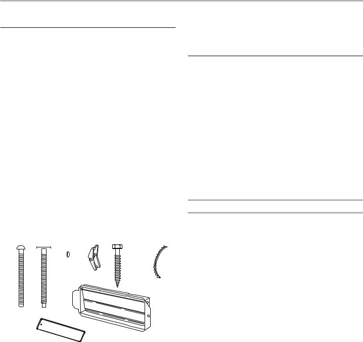
Parts supplied
■Diagonal wire cutting pliers
■Stud finder
■7/16" (1.1 cm) socket wrench (or box wrench) for 1/4" x 2" (0.6 cm x 5.1 cm) lag screws
■11⁄2" (3.8 cm) diam. hole drill bit for wood or metal cabinet
■Keyhole saw
■Caulking gun and weatherproof caulking compound
■Duct tape
For information on reordering, see the “Replacement Parts” section.
NOTE: The hardware items listed here are for wood studs. For other types of wall structures, be sure to use appropriate fasteners.
A  B
B C
C  D E
D E  F
F  G
G
H
J
A.3/16 - 24 x 3" (7.6 cm) round-head bolts (2)
B.1/4 - 20 x 3" (7.6 cm) flat-head bolts
(2)
C.Washers (2)
D.3/16" (4.8 mm) toggle nuts (2)
E.1/4" x 2" (0.6 cm x 5.1 cm) lag screws (2)
F.Sheet metal screws 5/32" x 5/16" (0.4 cm x 0.8 cm) (2)
G.Power supply cord bushing (1)
H.Damper assembly (for wall or ro venting)
J. Exhaust vent cover (2)
Not Shown:
■Mounting plate (Located on the upper polyfoam)
■Grease filters
■Charcoal filters
NOTE: Depending on model, grease filter and charcoal filter may be combined.
Materials Needed
Standard fittings for wall or roof venting. See the “Venting Design Specifications” section.
Location Requirements
IMPORTANT: Check the opening where the microwave oven will be installed. The location must provide:
■Minimum installation dimensions. See the “Installation Dimensions” illustration.
■Minimum one 2" x 4" (5.1 cm x 10.2 cm) wood wall stud and minimum 3/8" (9.5 mm) thickness drywall or plaster/lath within cabinet opening.
■Support for weight of 150 lbs (68 kg) which includes microwave oven and items placed inside the microwave oven and upper cabinet.
■Grounded electrical outlet inside upper cabinet. See the “Electrical Requirements” section.
NOTE: Some cabinet and building materials are not designed to withstand the heat produced by the microwave oven for cooking. Check with your builder or cabinet supplier to make sure that the materials used will not discolor, delaminate, or sustain other damages.
Special Requirements
For Wall Venting Installation Only:
■Cutout must be free of any obstructions so that the vent fits properly and the damper blade opens freely and fully.
For Roof Venting Installation Only:
■If you are using a rectangular-to-round transition piece, the 3" (7.6 cm) clearance needs to exist above the microwave oven so that the damper blade can open freely and fully. See “Rectangular to Round Transition” illustration in the “Venting Design Specifications” section.
3

Installation Dimensions
NOTE: The grounded 3 prong outlet must be inside the upper cabinet. See the “Electrical Requirements” section.
A B
30" (76.2 cm) min.
24" (61 cm) typical*
60" ( 152.4 cm) min.
12" (30.5 cm) min.
14" (35.6 cm) max.
upper cabinet and side cabinet depth
A.2" x 4" (5.1 cm x 10.1 cm) wall stud
B.Grounded 3 prong outlet
*24" (61 cm) is typical for 60" (152.4 cm) installation height exact dimensions may vary depending on type of range/cooktop below.
NOTE: To ensure good performance, do not obstruct top vent airflow. If cabinets are deeper than 14" (35.6 cm) but no more than 15" (38.1 cm), use the bump out mounting kit replacing the mounting plate from the wall. The bump out mounting kit (part # W11185746) is not provided but can be purchased from Whirlpool.
12" DEPTH 14" |
|
14" DEPTH 15" |
mounting plate |
Bump out mounting |
|
|
|
bracket |
Product Dimensions
*Overall depth of product will vary slightly depending on door design.
10 |
" |
(26.2 cm) |
|
18" |
|
(45. |
|
5 |
cm) |
|
|
10 |
" |
(26.2 cm)
|
.0cm) |
29 |
"(76 |
|
Electrical Requirements
 WARNING
Electrical Shock Hazard Plug into a grounded 3 prong outlet. Do not remove ground prong.
Do not use an adapter.
Do not use an extension cord.
Failure to follow these instructions can result in death, fire, or electrical shock.
Observe all governing codes and ordinances.
Required:
■A 120 V, 60 Hz, AC only, 15 A or 20 A electrical supply with a fuse or circuit breaker
Recommended:
■A time-delay fuse or time-delay circuit breaker
■A separate circuit serving only this microwave oven
GROUNDING INSTRUCTIONS
■For all cord connected appliances:
The microwave oven must be grounded. In the event of an electrical short circuit, grounding reduces the risk of electric shock by providing an escape wire for the electric current. The microwave oven is equipped with a cord having a grounding wire with a grounding plug. The plug must be plugged into an outlet that is properly installed and grounded.
WARNING: Improper use of the grounding plug can result in a risk of electric shock. Consult a qualified electrician or serviceman if the grounding instructions are not completely understood, or if doubt exists as to whether the microwave oven is properly grounded.
Do not use an extension cord. If the power supply cord is too short, have a qualified electrician or serviceman install an outlet near the microwave oven.
SAVETHESE INSTRUCTIONS
4
INSTALLATION INSTRUCTIONS
The Microwave oven is set for recirculation installation. For wall or roof venting, changes must be made to the venting system.
NOTE: Skip below sections if you are using recirculation installations. Go to section “Locate Wall Stud(s)”. Keep the damper assembly in case the venting method is changed or the microwave oven is reinstalled in another location where wall or roof venting may be used.
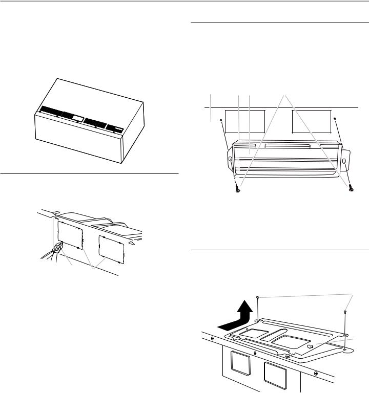
Wall Venting Installation Only
1.Using diagonal wire cutting pliers, gently snip out the rectangular vent covers on the damper plate.
A
B
A.Diagonal wire cutting pliers
B.Damper vent covers
Install Damper Assembly
(for wall venting only)
1.Check that damper blade moves freely, and opens fully.
2.Position the damper assembly on the back of the microwave oven so that the damper blade hinge is at the top, and the damper blade opens away from the microwave oven.
A B C D
A.Back of microwave oven
B.Damper assembly
C.Damper blade
D.Sheet metal screw 5/32" x 5/16" (4 mm x 8 mm)
3.Secure damper assembly with two sheet metal screws 5/32" x 5/16" (4 mm x 8 mm).
Roof Venting Installation Only
1.Remove screws attaching damper plate to top of microwave oven exterior. Slide damper plate toward the front of the microwave oven and lift up.
A
 B
B
A.Screws
B.Damper plate
5

Install Damper Assembly
(for roof venting only)
1.Check that damper blade moves freely, and opens fully.
2.Position the damper assembly on the top of microwave oven so that the damper blade hinge is at the top, and the damper blade opens away from the microwave oven.
A
B |
C |
 D
D
2. Rotate C 180 degrees, place it as shown below.
° 180
C
C.Recirculation lighting cover
3.Take J from packaging upper foam (see item J in “Parts Supplied” section), attach both of them as shown below with screw removed from step 1.
A
A.Screws
B.Damper blade
C.Damper assembly
D.Top of the microwave oven
3.Secure damper assembly with two sheet metal screws 5/32" x 5/16" (4 mm x 8 mm).
NOTE: To ensure good performance of airflow, for Wall and Roof venting, remove the charcoal filter from the bottom plate before operating the microwave oven.
Charcoal Filter
Grease Filter 
Vent Cover Installation
(for both wall and upper vent installation)
1.Remove screws attaching B and C covers. Slide them out. Keep cover C for use in Step 2.
A
J
A. Screws
J. Exhaust vent covers
Locate Wall Stud(s)
NOTE: If no wall studs exist within the cabinet opening, do not install the microwave oven.
See illustrations in “Possible Wall Stud Configurations.”
1.Using a stud finder, locate the edges of the wall stud(s) within the opening.
2.Mark the center of each stud and draw a plumb line down each stud center. See illustrations in “Possible Wall Stud Configurations.”
B
C
B
A.Screw
B.Recirculation vent covers
C.Recirculation lighting cover
NOTE: Keep B for future recirculation vent installation.
6
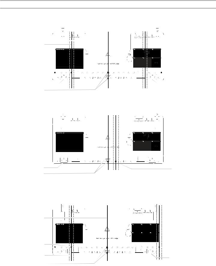
Possible Wall Stud Configurations
These depictions show examples of preferred installation configurations with the mounting plate.
No Wall Studs at End Holes
Figure 1
B 
 C
C
C
D 


 D
D
A 


 A
A
R E A R W A L L R E A R W A L L
E E
F
No Wall Studs at End Holes
Figure 2
B 
 C
C
A 


 A
A
R E A R W A L L R E A R W A L L
E  E
E
D
F
NOTE: If wall studs is within 6" (15.2 cm) of the vertical centerline (see “Mark Rear Wall” section), only recirculation or roof venting installation can be done.
Wall Studs at End Holes
Figure 3
B
D |
|
|
|
|
|
|
|
|
A |
|
|
|
|
|
|
A,D |
|
|
|
|
|
|
||||
E |
|
|
|
R E A R W A L L |
R E A R W A L L |
|||
C |
|
|
|
|
|
|
C |
|
|
|
|
|
|
|
|||
|
|
|
|
|
|
E |
||
|
|
|
|
|
|
|
|
|
F |
|
|
|
|
|
|
|
|
|
|
A. End holes (on mounting plate) |
D. Holes for lag screws |
|||||
|
|
B. Cabinet opening vertical centerline |
E. Support tabs |
|||||
|
|
C. Wall stud centerlines |
F. Mounting plate center markers |
|||||
7
Wall Studs at End Holes
Figure 4
B
A,D
E |
|
|
R E A R W A L L |
R E A R W A L L |
||
C |
|
|
|
|
|
|
|
|
|
||||
F |
|
|
||||
A. End holes (on mounting plate) |
|
D. Holes for lag screws |
||||
B. Cabinet opening vertical centerline |
E. Support tabs |
|||||
C. Wall stud centerlines |
|
F. Mounting plate center markers |
||||
A,D
C
E
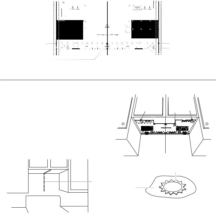
Prepare Upper Cabinet
You can find the quick reference guide direct from the mounting plate marking, or use this installation guide for installation.
See below install steps:
1.Disconnect power to outlet.
2.Remove all contents from upper cabinet.
3.Mark centerline on bottom of upper cabinet. Place mounting plate against the bottom of the upper cabinet. Make sure the mounting plate centerline aligns with the vertical centerline on the rear wall.
The “Rear wall” arrows must be against the rear wall so that the holes cut into the upper cabinet align with the holes in the top of the microwave oven.
NOTE: If the wall behind the microwave oven (as installed) has a partial wall covering (for example, tiled wall), be sure the “Rear Wall” arrows align to the thickest part of the rear wall (for example, to the tiles, rather than the drywall).
A
A.Centerline
4.Place mounting plate against the bottom of upper cabinet line and mark power supply hole “G” and 2 mounting holes “D” and “E” as shown in following figure. Make sure the 103⁄4" (27.3 cm) dimension from the rear wall to “D” and “E” on the mounting plate is maintained. And 11⁄2" (3.8 cm) diameter for “G” hole. Then cut the holes of “D”, “E” and “G”.
D 

 G E
G E
t
NOTE: If upper cabinet is metal, the supply cord bushing needs to be installed around the supply cord hole as shown.
B
A
A.Metal cabinet
B.Power supply cord bushing
5.Drill 3/8" (9.5 mm) holes at points “D” and “E” on the mounting plate. These are for two 1⁄4 - 20 x 3" (7.6 cm) bolts and washers used to secure the microwave oven to the upper cabinet.
NOTE: If replacing a range hood that has the direct wire power supply coming from the wall, install outlet box accessory kit
in upper cabinet. The Outlet Box Kit (part #W11082816) is not provided but can be purchased from Whirlpool.
8
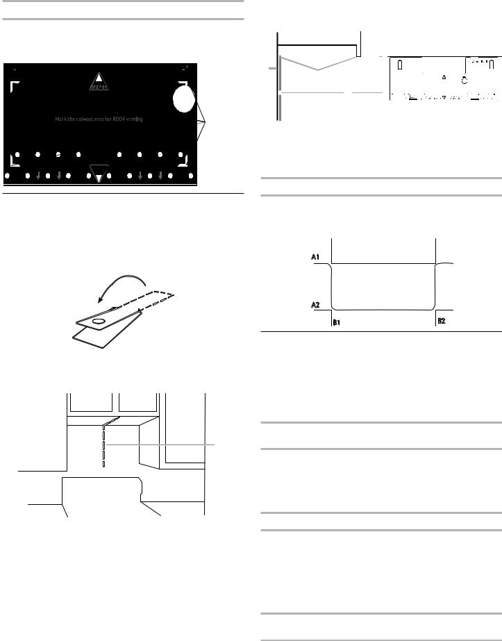
Roof Venting Installation Only
If venting through the roof, mark and trace the corner punches on the mounting plate. Set mounting plate aside, cut the venting area out from the bottom of the upper cabinet using a keyhole saw.
4 Corners
R E A R W A L L 
 R E A R W A L L
Mark Rear Wall
The microwave oven must be installed on a minimum of 1 wall stud, preferably 2, using a minimum of 1 lag screw, preferably 2.
1.Fold 2 mounting tabs forward into the tab cutout. Note that the tabs will NOT be flush after folding.
Fold Forward
2.Mark centerline on the back wall. Place mounting plate against the back wall, find and clearly mark the vertical centerline of the opening.
A
A.Centerline
3.Align the center markers on the mounting plate to the centerline of the wall. Make sure it is leveled and top of the mounting plate is butted up against the bottom edge of the upper cabinet.
NOTE: If the front edge of the upper cabinet is lower than the back edge, lower the mounting plate so that its top is leveled with the front edge of the cabinet.

 D
D
A 
C
B
A.Rear wall
B.Mounting plate
C.Top of mounting plate must align with front edge of cabinet
D.Front edge of upper cabinet
Wall Venting Installation Only
4.If venting through the wall, place mounting plate on the wall and mark the cut-out area. Set mounting plate aside, then using a keyhole saw, cut out hole in the wall at back venting area.
A1
Cut-out area for
BACK WALL Venting
A2
B1 |
B2 |
Drill Holes in Rear Wall
In addition to being installed on at least 1 wall stud, the mounting plate must attach to the wall at both end holes. If the end holes are not over wall studs, use two 3/16-24 x 3" (7.6 cm) round head bolts with toggle nuts; if 1 end hole is over a wall stud, use 1 lag screw and one 3/16-24 x 3" (7.6 cm) round-head bolt with toggle nut; or if both end holes are over wall studs, use 2 lag screws. Following are 3 installation configurations.
Installation for No Wall Studs at End Holes (Figures 1 and 2)
1.Drill 5/8" (1.6 cm) holes through the wall at both end holes marked in Step 3 of “Mark Rear Wall.”
2.Drill 3/16" (5 mm) hole(s) into the wall stud(s) at the hole(s) marked in Step 6 of “Mark Rear Wall.” Refer to figures 1 and 2 in “Possible Wall Stud Configurations” in the “Locate Wall Stud(s)” section.
Installation for Wall Stud at One End Hole (Figure 3)
1.Drill a 3/16" (5 mm) hole into the wall stud at the end hole marked in Step 3 of “Mark Rear Wall.”
2.If installing on a second wall stud, drill a 3/16" (5 mm) hole into the wall stud at the other hole marked in Step 6 of “Mark Rear Wall.” Refer to Figure 3 in “Possible Wall Stud Configurations” in the “Locate Wall Stud(s)” section.
3.Drill a 5/8" (1.6 cm) hole through the wall at the other end hole.
Installation for Wall Studs at Both End Holes (Figure 4)
1.Drill 3/16" (5 mm) hole into the wall stud at the end hole marked in Step 3 of “Mark Rear Wall.”
9
Loading...