

Whirlpool WF163SE1 Owner's Manual

16" (40.6 CM) STAND FAN
Use & Care Guide
For questions about features, operation/performance, parts
or visit our website at... www.whirlpoolairpurifiers.com
or service, call: 1-866-990-7365.
VENTILADOR DE PIE DE 16"
(40,6 CM) DE DIÁMETRO
Manual de uso y cuidado
Si tiene preguntas respecto a las características, funcionamiento,
o visite nuestro sitio de internet en... www.whirlpoolairpurifiers.com
rendimiento, partes o servicio técnico,
llame al: 1-866-990-7365.
VENTILATEUR SUR
SUPPORT DE 16" (40,6 CM)
DE DIAMÈTRE
Guide d’utilisation et d’entretien
Au Canada, pour assistance, installation ou service,
ou visitez notre site web à... www.whirlpoolairpurifiers.com
composez le : 1-866-990-7365.
WF16SFPF
Table of Contents/Índice/Table des matières ...... 2
Model/Modelo/Modèle : WF163SE1

TABLE OF CONTENTS
FAN SAFETY...................................................................................2
ELECTRICAL REQUIREMENTS....................................................3
Electrical Connection ...................................................................3
Fused Plug and Cord Information................................................3
FAN ASSEMBLY INSTRUCTIONS................................................4
Fan Base and Pole.......................................................................4
Fan Head and Fan Guard.............................................................4
ÍNDICE
SEGURIDAD DEL VENTILADOR...................................................8
REQUISITOS ELÉCTRICOS ..........................................................8
Conexión eléctrica........................................................................8
Información acerca del enchufe con fusible y el cable ...............9
INSTRUCCIONES DE ENSAMBLAJE DEL VENTILADOR........10
Base y poste del ventilador........................................................10
Cabezal y cubierta del ventilador...............................................10
TABLE DES MATIÈRES
SÉCURITÉ DU VENTILATEUR ....................................................14
SPÉCIFICATIONS ÉLECTRIQUES..............................................14
Raccordement électrique...........................................................14
Informations sur la fiche avec fusible
et le cordon d'alimentation ........................................................15
INSTRUCTIONS D’ASSEMBLAGE DU VENTILATEUR.............16
Base et tige principale du ventilateur.........................................16
Tête et grille de protection du ventilateur..................................16
FAN OPERATING INSTRUCTIONS...............................................5
Control Panel................................................................................5
Remote Control—On Some Models............................................6
FAN CARE.......................................................................................6
Cleaning........................................................................................6
ASSISTANCE OR SERVICE...........................................................6
In the U.S.A. and Canada.............................................................6
WARRANTY ....................................................................................7
INSTRUCCIONES PARA EL FUNCIONAMIENTO DEL
VENTILADOR................................................................................11
Panel de control .........................................................................11
Control remoto — En algunos modelos ....................................12
CUIDADO DEL VENTILADOR .....................................................12
Limpieza .....................................................................................12
AYUDA O SERVICIO TÉCNICO...................................................12
En los EE.UU. y Canadá.............................................................12
GARANTÍA.....................................................................................13
INSTRUCTIONS D’UTILISATION DU VENTILATEUR ...............17
Tableau de commande ..............................................................17
Télécommande—Sur certains modèles ....................................18
ENTRETIEN DU VENTILATEUR..................................................18
Nettoyage ...................................................................................18
ASSISTANCE OU SERVICE.........................................................18
Aux États-Unis et au Canada.....................................................18
GARANTIE.....................................................................................19
FAN SAFETY
Your safety and the safety of others are very important.
We have provided many important safety messages in this manual and on your appliance. Always read and obey all safety
messages.
This is the safety alert symbol.
This symbol alerts you to potential hazards that can kill or hurt you and others.
All safety messages will follow the safety alert symbol and either the word “DANGER” or “WARNING.”
These words mean:
All safety messages will tell you what the potential hazard is, tell you how to reduce the chance of injury, and tell you what can
happen if the instructions are not followed.
SAFETY FIRST BOX
DANGER
WARNING
You can be killed or seriously injured if you don't immediately
follow instructions.
can be killed or seriously injured if you don't
You
instructions.
follow
2
IMPORTANT SAFETY INSTRUCTIONS
WARNING: To reduce the risk of fire, electrical shock or injury when using your fan, follow these basic precautions:
Do not use fan if any parts are damaged or missing.
Do not expose to water or rain.
Do not use this fan with any solid state speed control
device.
Never insert finger or any other objects through the grille
guard when fan is in operations.
Unplug power cord when moving from one location to
another.
Unplug power cord when removing grille for cleaning.
Be sure fan is on a stable, flat surface when in operation.
Do not use fan in window; rain and moisture may create
electrical hazard.
Do not alter the fan's assembly in any way.
Be sure front and rear grille screws are tightened before
operation.
SAVE THESE INSTRUCTIONS
ELECTRICAL REQUIREMENTS
Electrical Connection
■ To properly install your fan, plug the 2 prong power cord into
a grounded 120V outlet.
■ This appliance has a polarized plug (one blade is wider than
the other). To reduce the risk of electric shock, this plug is
intended to fit in a polarized outlet only one way.
Fused Plug and Cord Information
WARNING
Electrical Shock Hazard and Fire Hazard
Always unplug this product before installing or
replacing fuses.
Do not operate any fan with a damaged cord or plug.
Discard fan or return to an authorized service facility
for examination and/or repair.
Do not run cord under carpeting.
Do not cover cord with throw rugs, runners, or similar
coverings.
Do not route cord under furniture or appliances.
Arrange cord away from traffic area and where it will
not be tripped over.
Failure to follow these instructions could result in
shock or fire hazard.
NOTES:
■ This product employs overload protection (fuse). A blown
fuse indicates an overloaded or short-circuit situation. If the
fuse blows, unplug the product from the outlet. Replace the
fuse as per the user servicing instructions below (follow the
product marking for proper fuse rating) and check the
product. If the replacement fuse blows, a short circuit may be
present and the product should be discarded or returned to
an authorized service facility for examination and/or repair.
If the plug does not fit fully in the outlet, reverse the plug. If it
still does not fit, contact a qualified electrician. Do not
attempt to defeat this safety feature.
■ This fan is rated at 120 VAC, 60 Hz, 45 W.
■ If your fan loses power and you suspect that the fuse on your
fan has blown, replace the fuse. See the following steps for
replacing the fuse.
1. Disconnect power by unplugging the fan. Grasp the plug and
remove from the receptacle or other outlet device.
NOTE: Do not unplug by pulling on the cord.
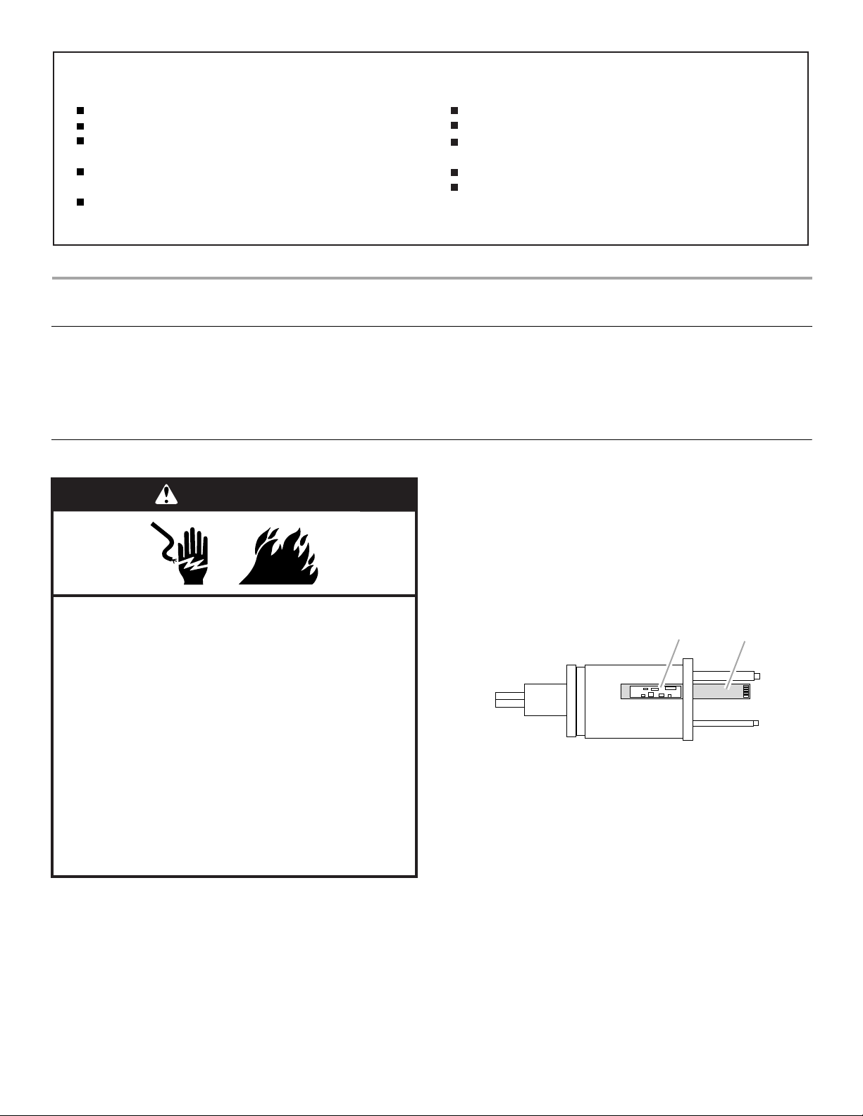
2. Slide open the fuse door on the side of the plug. Be sure the
fuse door is open completely and the blown fuse is fully
visible.
A
placeholder
A. Fuse
B. Fuse door
3. Remove the blown fuse.
4. Snap the 5-amp, 125-volt replacement fuse into place.
5. Fully close the fuse door by sliding back into place.
6. Discard the blown fuse.
7. The fan should now be ready for normal use.
IMPORTANT: Risk of fire. Do not replace attachment plug.
Contains a safety device (fuse, AFCI, SCDI) that should not be
removed. Discard product if the attachment plug is damaged.
Failure to follow these instructions can result in death or fire.
B
3

FAN ASSEMBLY INSTRUCTIONS
H
Fan Assembly
A
TU S R NO
Q P
V
A. Fan guard mounting nut
B. Motor shaft
C. Tilt adjustment knob
D. Fan head assembly
E. Hand screw
F. Extension pole
G. Pole extension screw
H. Main pole
I. Cross base sheath
J. Cross base
K. Cross base screws (4)
L. Fan control pad
M. Prongs
N. Rear fan guard
O. Notches
P. F an bl ad e
Q. Fan blade securing screw
R. Fan guard washer
S. Fan guard clip
T. Fan guard screw
U. Front fan guard
V. Remote control (some models)
Fan Base and Pole
1. Slide the main pole onto the cross base. Check that the
4holes align.
2. Use the 4 cross base screws to attach the main pole to the
cross base.
3. Slide the cross base sheath onto the main pole.
4. Loosen the pole extension screw and raise the extension pole
fully.
5. Retighten the pole extension screw.
6. Remove the hand screw from the fan head assembly.
7. Insert the neck of the fan head assembly into the extension
pole.
8. Retighten the hand screw.
B
C
D
M
E
F
L
G
I
J
K
Fan Head and Fan Guard
1. Unscrew the fan blade securing screw.
NOTE: Turn the fan blade securing screw clockwise to
remove.
2. Remove the rear fan guard mounting nut.
3. Place the rear fan guard over the motor shaft, with the
notches, 2 at the top and 1 at the bottom, sliding over the
corresponding prongs on the motor housing.
NOTE: Check that the rear fan guard fits tightly against the
motor housing.
4. Use the rear fan guard mounting nut to attach the rear fan
guard to the motor housing. Tighten firmly.
5. With the hollowed interior of the blade facing toward the rear
fan guard, slide the fan blade firmly onto the motor shaft.
NOTE: The top of the motor shaft should align with the center
of the fan blade.
6. Use the fan blade securing screw to lock the fan blade into
place.
NOTE: Turn the fan blade securing screw counterclockwise
to tighten. Do not overtighten.
7. Keep the logo on the logo plate on the front fan guard parallel
with the floor.
8. With the front fan guard held against the rear fan guard, hook
the top outer edge of the front fan guard over the top outer
edge of the rear fan guard.
9. Gently push the front and rear fan guards together until the
clips around the outer edge snap into position.
10. If the front fan guard does not fit evenly around the rear fan
guard, remove the front fan guard and reinstall.
11. With the front of the fan guard facing you, insert the fan guard
screw through the hole in the bottom of the fan guard.
12. Place the fan guard washer onto the screw.
13. Slide the fan guard clip onto the screw.
14. Align the fan guard clip with the hole on the fan guard and
push in to secure clip.
15. Tighten the fan guard screw completely.
NOTE: Do not overtighten.
4

FAN OPERATING INSTRUCTIONS
B
C
D
E
F
G
H
I
Control Panel
A
2
1
0
.
A. Sleeping breeze mode
indicator light
B. Natural breeze mode
indicator light
C. Fan speed indicator lights
D. Timer indicator lights
E. Off button
5
4
F. Timer button
G. Natural breeze/Sleeping
breeze mode button
H. Oscillation button (on some
models)
I. On/Fan speed button
1. Set fan on a dry, level surface.
2. Plug in fan.
3. Press the On/Fan Speed button to select the desired fan
speed. Choose High (III), Medium (II) or Low (I). See “On/Fan
Speed.”
4. Press the Oscillation button (on some models) or push down
on the Oscillation control (on some models) to start
oscillation. See “Oscillation.”
On/Fan Speed
Timer
1. Press the Timer button once to set the fan to turn off after
30 minutes. The 0.5h Timer indicator light will turn on.
2. Each time that the Timer button is pressed, 30 minutes is
added to the time when the fan will turn off up to 7 hours
30 minutes. For example, if the Timer button is pressed
6 times, the 2h, 1h and 0.5h indicator lights will turn on, and
the fan will turn off after 3 hours 30 minutes.
Oscillation
1. Press the Oscillation button to turn on oscillation.
2. Press the Oscillation button again to turn off oscillation.
Natural Breeze/Sleeping Breeze
Natural Breeze Mode
1. Press the Natural Breeze/Sleeping Breeze mode button once.
2. The Natural Breeze indicator light turns on. The fan alternates
between fan speeds to imitate a natural breeze.
3. To turn off the Natural Breeze Mode, press the Natural
Breeze/Sleeping Breeze mode button 2 times.
1. Press the On/Fan Speed button. The fan will operate on Low
(I) fan speed.
2. Press the On/Fan Speed button again to choose Medium (II)
or High (III) fan speed.
3. The Fan Speed indicator lights will turn on for the selected
fan speed.
Sleeping Breeze Mode
1. Press Natural Breeze/Sleeping Breeze mode button twice.
2. Press the Timer button to select a time between 30 minutes
and 7 hours 30 minutes before the fan turns off. See “Timer.”
3. The Sleeping Breeze indicator light will turn on.
4. To turn off the Sleeping Breeze mode, press the Natural
Breeze/Sleeping Breeze mode button 1 time.
5

Remote Control—On Some Models
NOTE: The remote control requires 2 AAA batteries (not included)
for operation.
A
B
C
D
E
1. To install the batteries, depress the back of the remote, with
your thumb in the indentations, and remove the cover.
2. Insert the batteries according to the diagram shown inside.
3. Replace the cover.
4. To activate all function buttons, press On/Fan Speed button,
any button on the Remote Control or the control.
A. Off button
B. Timer button
C. Natural breeze/Sleeping breeze mode button
D. Oscillation button
E. On/Fan speed button
FAN CARE
Cleaning
■ Use a soft, damp cloth to clean all surfaces. Wipe dry with a
soft, dry cloth.
■ Do not use a cleaning solution that is damaging to paints or
plastics.
ASSISTANCE OR SERVICE
Before calling for assistance or service, please check
“Troubleshooting.” It may save you the cost of a service call. If
you still need help, follow the instructions below.
In the U.S.A. and Canada
Call the Customer Service Center toll free: 1-866-990-7365.
Our consultants provide assistance with:
■ Features and specifications on our full line of appliances.
■ Installation information.
■ Use and maintenance procedures.
■ Accessory and repair parts sales.
■ Specialized customer assistance (Spanish speaking, hearing
impaired, limited vision, etc.).
■ Referrals to local dealers, repair parts distributors and service
companies. Designated service technicians are trained to
fulfill the product warranty and provide after-warranty service,
anywhere in the United States and Canada.
■ Do not bend the blades.
■ The motor bearings are permanently sealed and do not
require additional lubrication.
When calling, please know the purchase date and the complete
model and serial number of your appliance. This information will
help us to better respond to your request.
To locate the designated service company in your area, you
can also look in your telephone directory Yellow Pages.
For further assistance
If you need further assistance, you can write to Master Brands
HK Limited with any questions or concerns at:
Master Brands HK Limited
c/o CCRG Teleservices
4240 Ridge Lea Road, Suite 29
Amherst, NY 14226
Please include a daytime phone number in your correspondence.
6
 Loading...