

Page 1
P-
Cardio Menu
Service Manual
I
Welc$Altynm
i
Sc
hiller
Q
Page 2
SP-1
User
Artide
Number2.510 271a
Guide
Copyright
0
'
97
&
Schiller
Welch Allyn Inc.
7420
Carroll
San Diego, CA
Phone:
United Kingdom:
Welch Allyn
Cubblington Road
Aston Abbotts
United Kingdom
Tel:
Fax:
'
98
by
Welch
Alp
UK
Ltd
HP22 4ND
01296-682-140
01296-682-104
schiller
(800)
Fax:
(858)
www.welchallyn.com
854-2904
621-6611
ii
Road
92121
Canada:
Welch Allyn Canada Ltd
160
Matheson Blvd. East, Unit
Mississauga, Ontario
Canada
Tel:
(800) 561-8797
Fax:
(905)
@
890-0008
L4Z
#2
1V4
Page 3
DECLA RA
TI0
N
0
F
CO
NFO
R
MIW
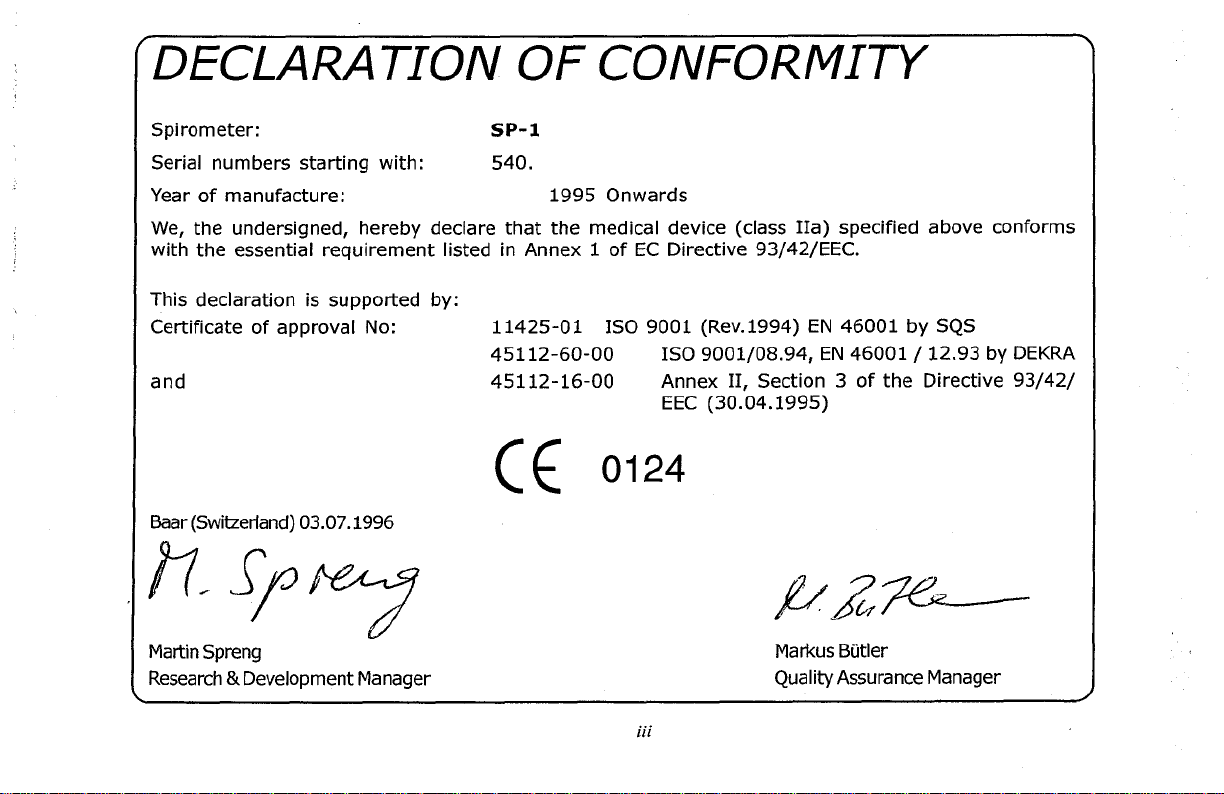
Spirometer:
Serial numbers starting with: 540.
Year of manufacture: 1995 Onwards
We, the undersigned, hereby declare that the medical device (class IIa) specified above conforms
with the essential requirement listed in Annex
This declaration is supported by:
Certificate of approval
and 45112-16-00 Annex 11, Section 3
bar (Switzerland) 03.07.1996
Martin Spreng
Research
ti
Development Manager
No:
SP-
1
1
of EC Directive 93/42/EEC.
11425-01 IS0 9001 (Rev.1994)
45112-60-00
(c
IS0 9001/08.94,
EEC
0124
(30.04.1995)
Markus Butler
Quality Assurance Manager
EN
46001 by SQS
EN
46001 / 12.93 by DEKRA
of
the Directive 93/42/
iii
Page 4
LXdlimer
TheInformationin thisguide has
of
the contents and WELCH AUYN SCHILLER makes no representations or warranties regarding the contents of this
manual. We resewethe rightto revise
within at any time without obligation
Trademaks
WELCH ALLYN SCHILLER and
property oftheir owners.
CoPynigM~
0
Copyright
1996
store
in a retrieval
optical, chemical, manual or otherwise, any
SCHILLER.
TWlllSOfwdnanly
WELCH AUYN SU-IILLER warrants the SP-1 Spirometer, when new, to be
and to
perform inaccordancewithmanufaburw'sspedficationsfortheperiodofthree(3)yearsfromthedateofpurchase
from
Welch Allyn or
limited to a wanantyof 90days fmmthedateof purchasefmm Welch Allyn or itsauthorized distributors oragents. Welch
Allyn will repairorreplaceany mponen tsfoundto bedefectiveoratvariancefrom
this time at no
authorized dimibuter,
misuse, neglect, accidents, modifications orshipping. This warranty is alsovoid ifthe instrument is not
with manufacturer's recommendations or if repaired by otherthan Welch Ally or an authorized agent. Purchase date
determineswarranty requirements. No otherexpress warranty isgiven.
and
system
it'
wst
to
the customer.
agentor~cerep-sentative.Thiswarrantydoesnot
beencarefullych~edforreliabliity;
this
document and make changes
to
notify any person of
SP-1
are registered trademarks of WELCH AUYN SCHILLER. All trademark are the
1998
by WELCH AUYN SCHIUER.
orhanslate into any language, in any
s
authorized distributors or agents. Accessoly items such as electrodes, batteries and cables are
part
It
shall be the purchasers responsibility to
All
of this oublication without
howevernoguaranteeisgivenastothewmxtness
in
wch
revision or change.
rights resewed. You may not
form
the specification
or by any means, elebmnic, mechanical, magnetic,
~XDRSS
written Dermission of WELCH AUT"
free
of defects
manufacturer'sspedfications
return
indudebreakage orfailuredueto tampering,
of
the prcduct described
repmduce,
hansmit,
In
material and workmanship
the insbument to Welch Allyn or an
used
hansaibe,
within
in
accordance
iv
Page 5
Schiller
PHYSICIAN’S RESPONSIBILITY
THE SP-1 SPIROMETER IS PROVIDED FOR THE EXCLUSIVE USE OF QUALIFIED
PHYSICIANS OR PERSONNEL UNDER THEIR DIRECT SUPERVISION. THE
NUMERICAL AND GRAPHICAL RESULTS FROM A RECORDING MUST BE
EXAMINED WITH RESPECTTO THE PATIENTS OVERALL CLINICAL CONDITION.
THE RECORDING PREPARATION QUALITY AND THE GENERAL RECORDED DATA
QUALITY, WHICH COULD EFFECTTHE REPORT DATA ACCURACY, MUST ALSO
BE TAKEN INTO ACCOUNT.
IT
IS THE PHYSICIANS RESPONSIBILITY TO MAKE THE DIAGNOSIS OR TO
OBTAIN EXPERT OPINION ON THE RESULTS, AND TO INSTITUTE CORRECT
TREATMENT IF INDICATED.
0
FEDERAL
ORDER OFA PHYSICIAN
LAW
IN THE USA RESTRICTS THIS DEVICE TO SALE BY OR ON THE
V
Page 6
Safety Notices
THIS UNIT IS BF CLASSIFIED ACCORDING TO IEC
601
-1.
1
SERVICING TO QUALIFIED PERSONNEL ONLY.
?
FLAMMABLE GASES SUCH AS ANAESTHETIC AGENTS.
THIS PRODUCTIS NOTDESIGNED FOR STERILE USE.
z
~
DO NOT, UNDER ANY CIRCUMSTANCES, IMMERSE THE UNITOR CABLE ASSEMBLIES IN LIQUID.
THE DEVICE MUST ONLY BE OPERATED USING BATTERY POWER IF THE EARTH CONNECTION IS SUSPECTOR IF
THE MAINS LEAD IS DAMAGED OR SUSPECTED
ZM
OR GAMMA R4DIATlON STERIUSAIION.
DO NOT USE SOLVENT CLEANERS
USE ONLYACCESSORIES AND OTHER PARTS RECOMMENDED OR SUPPLIED BY WELCH ALLYN SCHILLER. USE
OTHER THAN RECOMMENDED OR SUPPLIED PARTS MAY RESULTIN INJURY INACCURATE INFORMATIONAND/ OR
DAMAGE
THE
EMISSIONS AND ELECTRICAL INTERFERENCE. HOWEVER SPECIAL CARE MUST BE EXERCISED WHEN THE UNIT
IS USED WITH HIGH FREQUENCY EQUIPMENT.
TO
SP-1
THE UNn.
COMPLIES WITH EMC REGULATIONS FOR MEDICAL PRODUCTS WHICH AFFORDS PROTECTION AGAINST
OF
BEING DAMAGED.
vi
OF
Page 7
(
SP-I
This User's Guide gives instructions on how to operate the unit and provides an overview
easy and simple to use format. The procedures are presented in a logical, step-by step way to enable the user
and easily familiarisethemselves with unit operation. Detailed medical information
necessary to operate the unit
1
or
understand the results.
User's
vii
Guide
is
excluded from this guide except where
of
all the basic functions in an
to
quickly
Page 8
This equipment has been tested and found to comply with the limits for a class A digital device, pursuant to both Part
15
of the FCC (Federal Communications Commision) Rules and the radio interference regulations of the Canadian
Department of Communications. These limits are designed to provide reasonable protection against harmful interference
is
when the equipment
operated in a commercial environment. This equipment generates, uses and can radiate radio
frequency energy and, if not installed and used in accordance with this instruction manual, may cause harmful
interference to radio communications. Operation of this equipment in a residential area is likely to cause harmful
interference in which case the user will be required to correct the interference at his own expense.
Disposal Instructions
and Battery Care
DO NOT DISPOSE
DANGER OF EXPLOSION
O
DO NOT ATTEMPT TO RECHARGE THE BATTERY - DANGER
EXPLOSION
O
DO NOT OPEN THE BATTERY CASING - DANGER OF ACID BURN
Only dispose of the battery in official recycling centres
OF
THE BATTERY BY
FIRE
OR INCINERATOR
or
municipally approved
-
OF
O
areas. Alternatively used batteries can be returned to Schiller AG for disposal.
Unit Disposal Instructions
Units no longer required can be returned to Schiller AG for disposal. Alternatively
dispose of the unit in municipally approved recycling centres.
viii
Page 9
Schiller
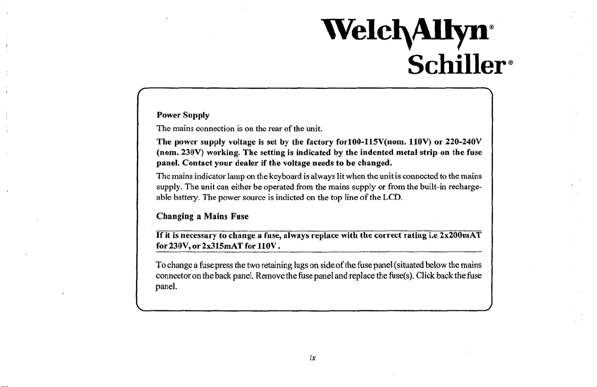
Power Supply
The mains connection
The power supply voltage is set by the factory for100-115V(nom. llOV) or 220-240V
(nom. 230V) working. The setting is indicated by the indented metal strip on the fuse
panel. Contact your dealer if the voltage needs
The mains indicator lamp
supply. The unit can either be operated
able battery. The power source is indicted
Changing a Mains Fuse
If it is necessary to change a fuse, always replace with the correct rating i.e 2x200mAT
for 230V, or 2x315mAT for
is
on
the rear of the unit.
to
be changed.
on
the keyboard is always lit when the unit is connected to the mains
from
llOV
.
the mains supply
on
the
top
line
or
from the built-in recharge-
of the LCD.
@
To change a fuse press the
connector
panel.
on
the back panel. Remove the fuse panel and replace the fuse(s). Click back the fuse
two
retaining lugs
on
ix
side
of
the fuse panel (situated below the mains
Page 10
Welc$AJlp-
Schiller
r
9314ZEEC Medical
0124
‘Notified
X
Devices:
Body’
DEKRA
AG
0
.
1
i
Page 11
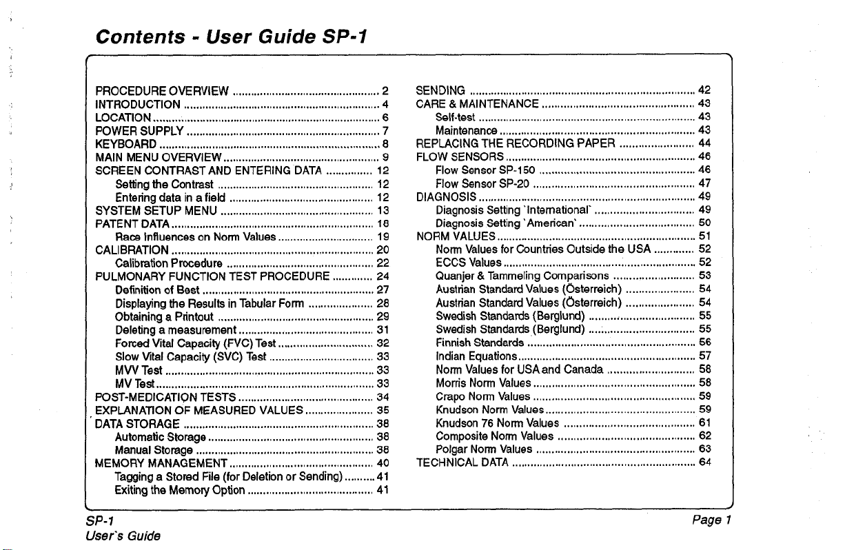
Contents . User Guide
SP-I
PROCEDURE OVERVIEW
INTRODUCTION
LOCATION
POWER SUPPLY
KEYBOARD
MAIN MENU OVERVIEW
SCREEN CONTRAST AND ENTERING DATA
Setting the Contrast
Entering data
SYSTEM SETUP MENU
PATENT DATA
Race Influences on Norm Values
CALIBRATION
Calibration Procedure
PULMONARY FUNCTION TEST PROCEDURE
Definition
Displaying the Results in Tabular Form
Obtaining a Printout
Deleting a measurement
Forced Vital Capacity (FVC) Test
Slow
Vital Capacity (SVC) Test
MW
Test
MV Test
POST-MEDICATIQN TESTS
EXPLANATION OF MEASURED VALUES
DATA STORAGE
Automatic Storage
Manual Storage
MEMORY MANAGEMENT
Tagging a Stored File (for Deletion or Sending)
Exiting the Memory Option
................................................................
..........................................................................
...............................................................
........................................................................
in
..................................................................
..................................................................
of
Best
....................................................................
.......................................................................
..............................................................
................................................
...................................................
...................................................
a field
...............................................
..................................................
...............................
................................................
........................................................
.....................
...................................................
............................................
...............................
..................................
............................................
......................
......................................................
..........................................................
...............................................
.........................................
...............
.............
..........
SENDING
2
CARE & MAINTENANCE
4
6
7
REPLACING THE RECORDING PAPER
8
FLOW SENSORS
9
12
12
DIAGNOSIS
12
13
18
NORM VALUES
19
20
22
24
27
28
29
31
32
33
33
33
34
35
38
38
38
TECHNICAL DATA
40
41
41
.........................................................................
Self-test
Maintenance
......................................................................
...............................................................
.............................................................
Flow Sensor
Flow Sensor
SP-150
SP-20
......................................................................
Diagnosis Setting 'International'
Diagnosis Setting 'American'
................................................................
Norm Values for Countries Outside the USA
ECCS Values
Quanjer & Tammeling Comparisons
Austrian Standard Values (Osterreich)
Austrian Standard Values (Osterreich)
Swedish Standards (Berglund)
Swedish Standards (Berglund)
Finnish Standards
Indian Equations
Norm
Morris Norm Values
Crapo Norm Values
Knudson Norm Values
Knudson
Composite Norm Values
Polgar Norm Values
..............................................................
......................................................
.........................................................
Values for
USA
76
Norm Values
...........................................................
.................................................
........................
..................................................
....................................................
................................
.....................................
.............
..........................
......................
......................
..................................
..................................
and Canada
............................
....................................................
....................................................
................................................
..........................................
............................................
...................................................
42
43
43
43
44
46
46
47
49
49
50
51
52
52
53
54
54
55
55
56
57
58
58
59
59
61
62
63
64
SP-1
User's
Guide
Page
1
Page 12
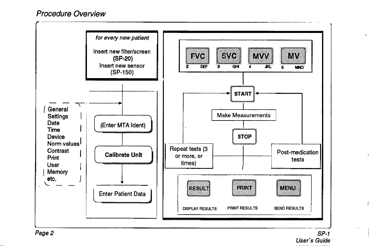
Procedure Overview
r
I
for
every new patient
Insert new filterkcreen
Insert new sensor
(SP-20)
(SP-150)
-1
\
2
OEF
3
GHI
4
JKL
5
MNO
-_
(
General
Settings
Date
Time
Device
Norm values
Contrast
Print
User
I
Memory
etc.
,L--
Page
2
-i-
.
I
Enter MTA ldent
1
Repeat tests
or more, or
times)
I
DISPLAY
I
I
I
I
I
I
(3
I
RESULTS PRINT RESULTS SEND RESULTS
I
I
Post-medication
tests
I
User's
1
SP-
Guide
I
!
',
1
i
Page 13
Procedure Overview
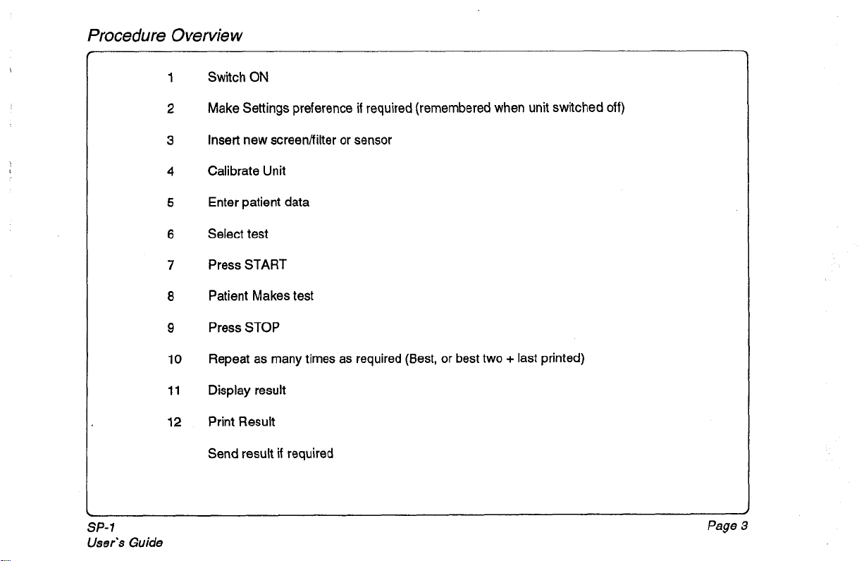
1
Switch
ON
Make Settings preference
2
Insert new screenAiIter or sensor
3
Calibrate Unit
4
Enter patient data
5
Select test
6
Press
7
8
9
10
11
12
START
Patient Makes test
Press
STOP
Repeat as many times
Display result
Print Result
Send result
if
required
if
required (remembered when unit switched
as
required (Best, or best two + last printed)
off)
SP-1
User’s
Guide
Page
3
Page 14
Introduction
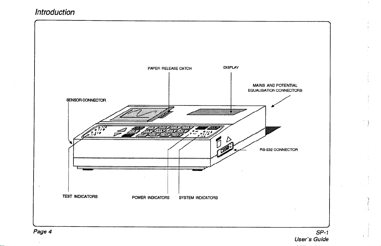
FNSOR CONNECTOR
PAPER RELEASE CATCH DISPLAY
I
MAINS AND POTENTIAL
EQUALISATION CONNECTORS
/
RS-232
CONNECTOR
Page
TEST
INDICATORS
4
POWER INDICATORS SYSTEM INDICATORS
,I
User's
SP-
Guide
1
Page 15
Introduction
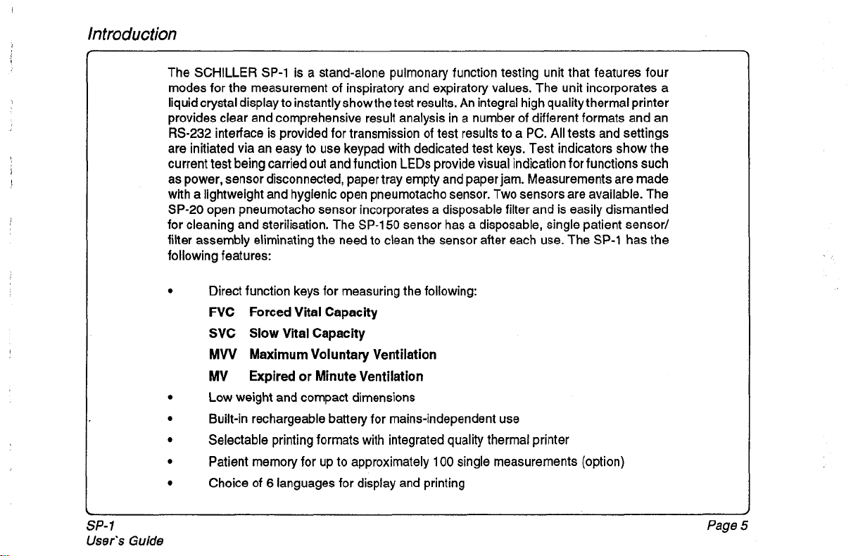
The SCHILLER
modes for the measurement of inspiratory and expiratory values. The unit incorporates a
liquidcrystal display to instantly showthetest results. An integral high quality thermal printer
provides clear and comprehensive result analysis in a number of different formats and an
RS-232
are initiated via an easy to use keypad with dedicated test keys. Test indicators show the
current test being carried
as power, sensor disconnected, paper tray empty and paper jam. Measurements are made
with a lightweight and hygienic open pneumotacho sensor. Two sensors are available. The
SP-20
for cleaning and sterilisation. The
filter assembly eliminating the need
following features:
interface is provided for transmission of test results to a
open pneumotacho sensor incorporates a disposable filter and is easily dismantled
Direct function keys for measuring the following:
FVC Forced Vital Capacity
SVC
MW
MV
Low weight and compact dimensions
Built-in rechargeable battery for mains-independent use
Selectable printing formats with integrated quality thermal printer
Patient memory for up to approximately
Choice of
SP-1
is a stand-alone pulmonary function testing unit that features four
out
and function
Slow
Vital Capacity
Maximum Voluntary Ventilation
Expired or Minute Ventilation
6
languages for display and printing
LEDs
SP-150
sensor has a disposable, single patient sensor/
to
clean the sensor after each use. The
PC.
All
tests and settings
provide visual indication for functions such
SP-1
has the
100
single measurements (option)
SP-
1
User's
Guide
Page
5
Page 16
Location
As
with all medical units, the following general rules are to be noted:
The unit should not be stored or operated in a wet, humid or dusty environment.
The unit may not come into contact with acidic steams or liquids.
The unit should not be set up near radiology or diathermic systems, or near large
transformers or electrical motors. Ensure that a minimum distance of
between the unit and the mains supply
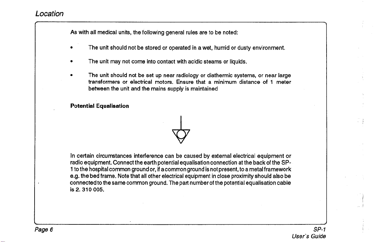
Potential Equalisation
In certain circumstances interference can be caused by external electrical equipment or
radio equipment. Connect the earth potential equalisation connection at the back
1
to the hospital common ground or,
e.g. the bed frame. Note that all other electrical equipment in close proximity should also be
connected to the same common ground. The part number of the potential equalisation cable
is
2.
31
0
005.
if
acommon ground is not present, to a metal framework
is
maintained
of
1
the
meter
SP-
Page
6
User's
SP-1
Guide
Page 17
Power
Supply
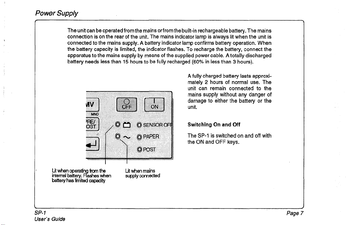
The unit can be operatedfromthe mains orfrom the built-in rechargeable battery. The mains
connection is on the rear of the unit. The mains indicator lamp is always lit when the unit is
connected to the mains supply.
the battery capacity is limited, the indicator flashes. To recharge the battery, connect the
apparatus to the mains supply by means
battery needs less than
A
battery indicator lamp confirms battery operation. When
of
the supplied power cable. A totally discharged
15
hours to be fully recharged
(60%
in less than 3 hours).
A
fully charged battery lasts approxi-
mately
2
hours of normal use. The
unit can remain connected to the
mains supply without any danger
damage to either the battery or the
unit.
of
SP-
1
User's
titwhenoperati fromthe
internal
battery.
#Lws
banery
Guide
has
limited
*en
capaaty
Lit
when mains
suppty
CoMected
Switching
The
SP-1
the
ON
and
On
and
Off
is switched on and
OFF
keys.
off
with
Page
7
Page 18
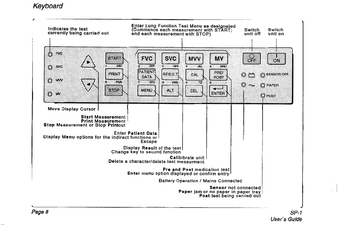
Keyboard
Indicates the test
currently being carried out
Move Display Cursor
Stop Measurement or Stop Printout
Display Menu options for the indirect functions or
I
Start Measurement
Print Measurement
Enter Patient Data
Change Rey to second function
Delete a character/delete last measurment
Enter Lung Function Test Menu as designated
(Commence each measurement with START; Switch Switch
end each measurement with
I
1
Escape
Dis lay Result of th test
Enter menu option displayed or confirm entry
STOP)
I
I
Calibibrate unit
Pre and Post medication test
Battery Operation / Mains Connectec
Paper jam or no paper in paper tray
Sensor not connected
Post test being carried out
unit off unit on
Page
8
User's
SP-1
Guide
Page 19

Main Menu Overview
Note that the Save and the Memory menu items only appear when the memory option is installed
SP-
1
User's Guide
Page
9
Page 20

Menu
Overview
Main
Menu
Page
10
Save
Memory
MTA ldent
Send
Setup
This option only appears when the memory option is installed. Select this
option to save the current measurement in the memory.
This option only appears when the memory option
is
installed. Select the
memory menu item to:
Print a stored recording
.
Delete a recording
.
Send a recording
Enter the name of the person carrying out the test. The MTA name (medical
technical Assistant)
remembered when the unit is switched
is
given on printouts. The users name entered here, is
off;
it
only needs updating when a new
user takes over.
Current recording
PC storage program). Note that the
is
sent overthe
RS-232
RS-232
interface (for example to the
SEMA
protocol settings must be defined
in the setup menu before transmission.
See System Setup Menu following
User's
SP-
1
Guide
,t
!
I
I
Page 21
Menu
Overview
SP-1
User's
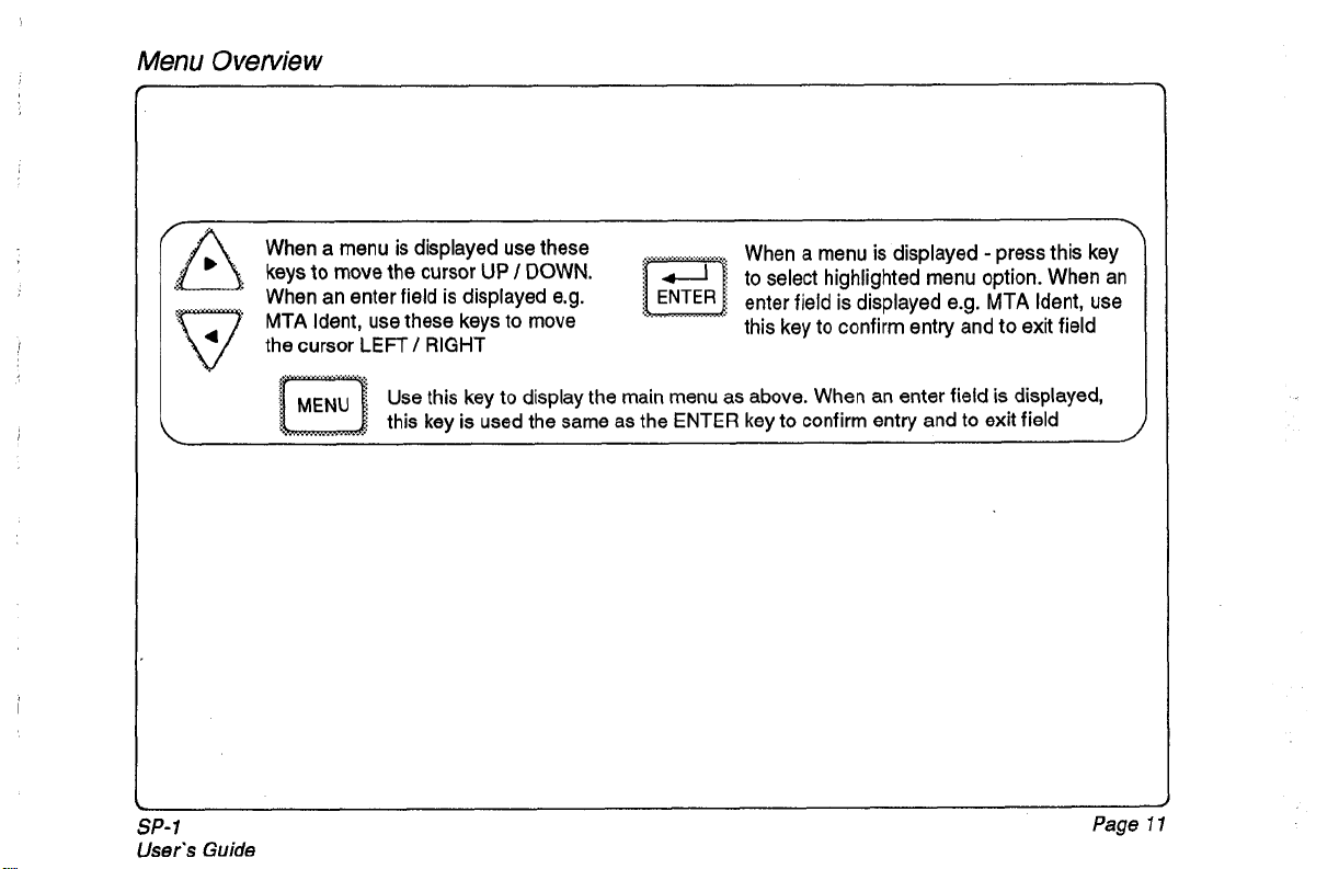
When a menu is displayed use these
keys
to
move the cursor
When an enter field is displayed e.g.
MTA
Ident, use these keys to move
the cursor
Guide
LEFT
/
RIGHT
Use this key to display the main menu as above. When an enter field
this key is used the same as the ENTER key to confirm entry and to exit field
UP
/
DOWN.
-
When a menu is displayed
to select highlighted menu option. When an
enter field
this key to confirm entry and to exit field
is
displayed e.g. MTA Ident, use
press this key
is
displayed,
Page
1
I1
Page 22
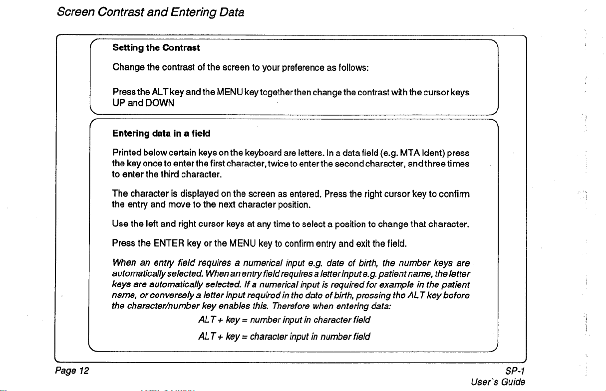
Screen Contrast and Entering Data
Change the contrast of the screen to your preference as follows:
Press the ALT key and the MENU key togetherthen change the contrast with the cursor keys
UP and DOWN
Page
12
User's Guide
SP-
I
Page 23
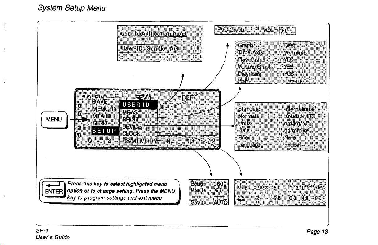
System Setup Menu
t
3-v-
7
User’s
Guide
Press this
Option or
key
key
to select highlighted menu
to
change setting.
to program settings and
Press
exit
the
menu
MENU
Page
13
Page 24
System Setup Menu
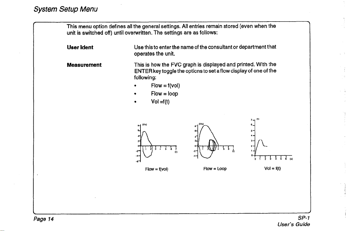
This menu option defines all the general settings.
unit is switched
User
ldent
Measurement
off)
until overwritten. The settings are as follows:
Use this to enter the name of the consultant
operates the unit.
This is how the FVC graph is displayed and printed. With the
ENTER
following:
key toggle the options to set aflow display of one
Flow = f(vol)
Flow = loop
Vol =f(t)
-8-l
Flow
=
f(v0l)
All
entries remain stored (even when the
or
department that
,
11)
Flow = LOOP
:kL
of
Vol
the
=
f(1)
Page
14
User's
SP-
Guide
I
Page 25
System Setup
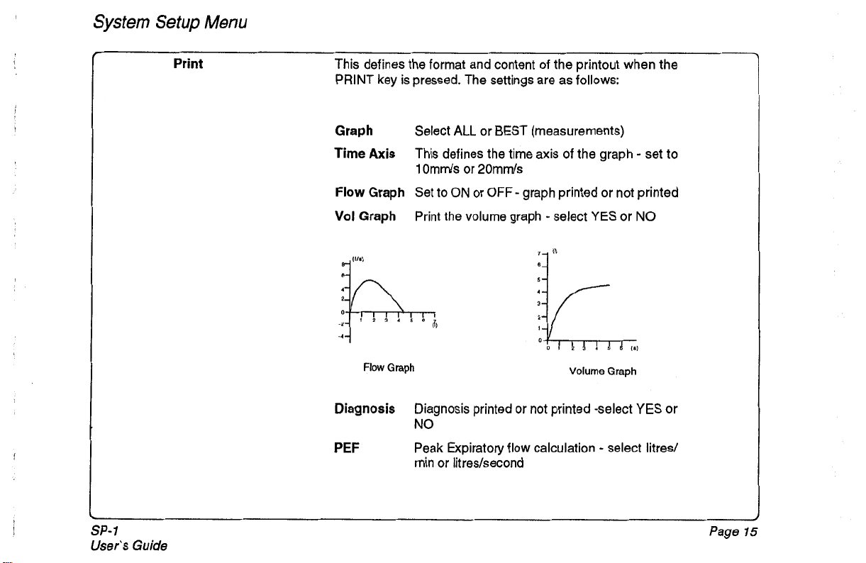
Print This defines the format and content of the printout when the
Menu
PRINT key is pressed. The settings are as follows:
SP-
1
User’s Guide
Graph Select
Axis
Time
Flow
Graph Set to ON or
Vol
Graph
111.1
Flow
Diagnosis
PEF
This defines the time axis of the graph - set
1
Omds or 20mm/s
Print the volume graph
Graph
Diagnosis printed
NO
Peak Expiratory flow calculation
min or litres/second
ALL
or BEST (measurements)
OFF - graph printed or not printed
-
select
YES
Volume
or
not
printed -select
-
to
or
NO
Graph
YES
or
select litred
Page
15
Page 26

System Setup Menu
Device
STANDARD
Set to 'International' for all countries outside the USA and
Canada or to 'American' for USA and Canada
NORMALS
The diagnosis is based on the standard defined here. The
Normal value standards are given at the end of this section'Diagnosis and Norm Value Tables'
UNITS
DATE
cm I kg IoC, cm I kg /OF,
settheorder ofthedatetomonth-day-year,
inch I Ib. 1°F
day- month-year
Set to
:
or year-month-day
RACE
set to:
NONE
(no
race): recommended for Europe,
WIB
(White1 Black) for all countries outside the USA and
Canada
CIHIBIA (Caucasian
/
Hispanic I Black I Asian) for USA and
Canada
The standards and Norm Values are detailed at the end of this
section (Diagnosis and Norm Values). The individual setting
for
race, and the effect of race on results is detailed in the
Patient data (see following page)
LANGUAGE This defines the language on the printout and menu structure.
to
English, German, French, Italian, Spanish, or Portuguese
Set
Page
16
1
Isnr's
SP-
Guide
1
Page 27

System Setup Menu
Clock
RSlMemory
Press the
shows
MENU
key to confirm all settings and exit the setup menu. The following table
typical setup combinations.
BERGLUND / QUANJER
FINNISH
INDIAN
OSTERREICH
KNUDSON
KNUDSON76
/
QUANJER
I
ITS
I
ITS
Set the time and date
The Baud rate
for sending over the
(300
to
38400)
RS
and parity setting (No/odd/even)
interface must be set to the same as
the receiving unit.
The save options are MAN (manual) or AUTO (automatic).
When the save option is set to AUTO, all measurements are
automatically saved when completed (only when the memory
option is installed).
(W/B)
International
or
NONE
cm/kglC
SP-
1
User‘s Guide
Page
17
Page 28

Patient Data
Each printout is complete with the name and other information concerning the patient. Before
beginning a recording, the patient data should be entered. The following parameters have to be
entered:
Pat-Name:
Pat-No:
Age:
Sex:
Height:
Weight:
Race:
Wrongly typed characters can be deleted by pressing the
Page
18
Patient name
Patient number
Enter age
Select
Height in centimetres (or inches
(scaled to
unit setup).
Weight in kilogrammes (or pounds,
depending on unit setup).
Enter patients race:
WIB:
C/H/B/A:
If
this position does not appear,
option <SETUP> <DEVICE> <RACE> see previous page.
of
patient in whole years
"M"
(male) or
1/10
"W
for White, "B" for Black
"C"
"F"
inch), depending on
for Caucasian,
(female).
"H"
for
"NONE"
'
Pat-Name
Pat-No
Age
Sex
Height
Weight
Race
was selected in the device setup. (menu
DEL
(delete) key.
:
years
(M/F)
cm
kg
SP-
1
User's Guide
Page 29

Patient Data
Race Influences
on
Norm
Values
According to the setting of the patients race the predicted values will differ. The differences
are (according to
When in the "Settings" menu
ITS
recommendations) as follows:
NONE
was set:
All values are calculated according to the given formulas.
When in the "Settings" menu
W
(White): values are calculated accordingtothe given formulas
B (Black):
85%
When in the "Settings" menu
C (Caucasian):
H (Hispanic):
B (Black):
A (Asian):
The
85%
race compensation is calculated only when the following normal
values are calculatedaccordingtothe given formulas
values are calculated according
85%
85%
values are selected: COMPOSITE;
(WB)
was set:
of the given formulas
(CMIB/A)
was set:
of the given formulas
of the given formulas
KNUDSON;
(=
1
OO0/o)
(=
100%)
to
the given formulas
(=
100%)
CRAPO; MORRIS; POLGAR
SP-
1
User's
Guide
Page
19
Page 30

Calibration
r
I
Page 20
Last calib.
BTPS
Calib.
Temperature
Measured
Syringe
THE UNIT MUST
THE DAY, AFTER EVERY SIGNIFICANT TEMPERATURE CHANGE
CHANGING THE SENSOR.
BE
Factor
Factor
Vol.
Vol.
IMPORTANT
CALIBRATED WITH THE FIRST PULMONARY FUNCTION TESTOF
23.1
1.090
1
.ooo
20
0.00
4.00
1.95
"C
I
I
OR
AFTER
User's
SP-
Guide
1
Page 31

Calibration
last Calibration
BTPS
Calibration Factor
Temperature
Measured Volume
Syringe Volume
date of last calibration
(=>
Factor calculated BTPS
Body Temperature, Ambient
Pressure, Saturated with water vapour) value. This value
compensatesforthe diff erence in inhaledand exhaled humidity.
The unit is set for measuring exhaled volume
so
Temp 36.8O), and
when inhaled volume is measured this
(1
00%
humidity,
factor is applied. The SP-1 uses ambient temperature to
calculate the BTPS factor. This is sufficient for accurate
FlVC
calculation. The formula used is as follow:
5
+
BTPS
=
0.033 + 273.1
273.1
5
+
36.8
T~
Tu is ambient temperature degrees centigrade
0.033 is equivialent to 760mmHg at
degrees
C
22
273.1 5 is degrees absolute
calculated value between measured and effective calibration
air volume
ambient temperature in
"C
(or
OF)
dependent on device setting
air volume measured by the system from the calibration pump
entered air volume depending on the size of the calibration
pump and times the air was pumped through the sensor; e.g.
pumping 2 litres 3 times amounts to
volume with a
2
litre pump is 4 litres; with 3 litre pump, 6 litres)
6
litres (the recommended
SP-
1
User's
Guide
Page
21
Page 32

Calibration
I
Calibration
To
calibrate the unit proceed as follows:
0
Note: Make
While pumping, the unit records the volume being pumped through the flow sensor and
indicates it on the display.
0
Procedure
Connect the calibration pump to the sensor. Ensure that there are no air leaks
Press the CAL key -the menu is displayed as shown on the previous page
The cursor is positioned at temperature. Enter the ambient temperature
Press ENTER when the correct temperature entered
Wait 1 second.
Press the START key
Pump 4 to 6 litres of air through the sensor
sure
that the flow sensor is kept still during the pumping operation.
Press the STOP key when finished pumping.
Enter the pumped air volume at syringe volume prompt (depending on the size of the
calibration pump and times of pumping; i.e. a
Press ENTER.
The message "Calibration complete " appears on the display, press the PRINT key
to
obtain a printout of the calibration report with the following information:
2
litre pump pumped3 times
=
6
litres).
Page
22
SP-
1
User's Guide
Page 33

Calibration
SP-1
User's Guide
If the message 'EXCESSIVE DEVIATION!' appears on the screen after a calibration,
indicates that the difference between the measured volume and the entered volume
great
(>25%).
volume. If these are all correct change the screen/filter and recalibrate
Check the temperature setting, the syringe volume and the entered syringe
is
too
it
Page
23
Page 34

Pulmonary Function Test Procedure
The test method for the FVC, SVC, MW and MV test
1.
Calibrate the unit
THE
UNIT
MUST
BE CALIBRATED
is
the same. Proceed as follows:
At the beginning of each day
If
the sensor is changed
When a significant temperature or pressure difference occurs
Press the function test key
2.
0
FVC
0
svc
MW
0
MV
The relevant keyboard lamp lights and the corresponding coordinate presentation appears
on the display as shown in this example for
FVC
The coordinates represent the graph on which the curve will be drawn with the respiratory
volume in litres being represented on the vertical axis and the time in seconds
horizontal
axis.
on
the
Page
24
User's
SP-
Guide
1
Page 35

Pulmonary Function Test Procedure
SP-
1
User's
Guide
Page
d
25
Page 36

Pulmonary Function Test Procedure
r
Press the START k eY
3.
The flow sensor must be heldquite stillandno air shouldbe breathedinto the device for at least one
second before and after the
The message "READY
counter graph for the value.
begins to record the expiratory flow. The corresponding curve is represented on the display. The
break-off point forthe expiration measurement is reached automatically (orthe Stop key is pressed).
4.
Press the STOP key on completion
5.
Repeat steps 3 and 4 until three measurements have been taken.
Note: If the Start key is again pressed (a
stored.
When American standards are stipulated, the message "ATS criteria met" appears on the printout
if
the deviation (as stipulated by the American Thorasic Society) between the best and second best
measurements is not greater than 200ml.
START
FOR
As
key
is
pressed.
MEASUREMENT' appears on the display together with a volume
soon as the patient starts to breathe into the flow sensor, the unit
of
the test.
fourth
or more times),
only
the best three measurements are
Page
26
SP-7
User's Guide
Page 37

Pulmonary Function Test Procedure
Following a series of patient measurements the best two results are recorded and stored
along with the last test made (which may
results can then
(from these three results). The table
screen.
~__
Definition
of
be
printed graphical along with a table of the best individual measurements
~~
Best
or
may not be one of the best three). These three
of
the best measurements can also be displayed on the
SP-
1
Uses’s
In accordance with the ATS Spirometry Standard (1 1 November
1994),
the best recordings
are defined as the highest value from the calculation:
The measurement table
measurements (e.g. FVC, FEVl
(on
the printout and on the display) gives the highest individual
,
SVC,
MW
etc.) from the two best recordings as defined
above, and the last recording made. This is true for all parameters except the following which
are based solely on the highest
Guide
FVC
+
FEVl value:
Page
27
Page 38

Pulmonary Function Test Procedure
FVC
svc
MV
Displaying
Press the
A
measurement table is displayedforthetest mode (as indicated bythetest lamp) asfollows:
the
Results in Tabular
RESULT
Key after a measurement, or series of measurements have been made.
Form
Page
28
User’s
SP-1
Guide
Page 39

Pulmonary Function Test Procedure
Obtaining a Printout
...............
Press after taking all measurements.
.............
SP-
I
User's
Guide
Page
29
Page 40

Pulmonary Function Test Procedure
The following is given:
The patient data
The selected norm values
The date of last calibration
The number of tests stored.
brackets indicates the total number of tests carried out. The number
stored, and the total number of post tests made are given in the same manner after
the slash. In the example given opposite, atotal of
of
6
post tests.
The
FVC
and
FEW
variation in ml between the best and second best measurements.
If
this value
The diagnostic statement (if enabled in Settings menu)
MTA
The
The user identification
The date and time of the printout
The software version and the installed options
bottom of this page.
is
within 200ml the message
identification
If
more than three tests are made the figure given in
of
post tests
5
tests were carried out and atotal
'ATS
criteria met' is printed.
(M
=
memory) are also indicz
3d at th
I
,
Page
30
User's
SP-
I
Guide
1
1
Page 41

Pulmonary Function Test Procedure
r
The second section of the printout comprises:
the test results presented as atable giving the best values, the predictedvalues and
the best values as a percentage*
*
The predicted values
would be obtained
predicted values on the printout are rounded to two decimalplaces, the processor
however,
%
exists, the values given on the printout are always the more accurate.
Deleting a measurement
The last measurement made can be deleted by pressing
uses
of
predicted value. This can account for a possible variation. Where a difference
(%)
given on the printout may differ slightly from the values that
if
manually calculated. The reason is that the measured and
the actual values -measured to three decimalplaces - to calculate the
of
the predicted.
DEL
3
SP-
1
User's Guide
Page
37
Page 42

Pulmonary Function
Test
Procedure
Forced
For this test the patient must exhale as quickly as possible from the time
Note:
To
coordinate presentation appears on the display
The patient must exhale as quickly as possible from the time of starting the test
that he understands what is required of him.
exhalation can be immediatelyfollowed by a maximum inhalation. The inspiration results will
be given on the printout.
Before initiating a printout of the FVC Test, ensure that the settings are correct as detailed
previously. Press the PRINT key to obtain a printout as defined.
Vital
Capacity (FVC)
NC
The
volume is too large
display
carry out the test for Forced Vital Capacity (FVC), press key "FVC and the corresponding
Test
of
starting the test.
test employs the "Back extrapolation" method. If the extrapolated
(>O.
15 litres or5%
of
FVC),
then a warning appears on the
so
be sure
If
inspiratory measurements are required, the
Page
32
SP-1
User's Guide
Page 43

Pulmonary Function Test Procedure
Slow
Vital Capacity (SVC) Test
The patient should breathe normally 3 times and then inhale maximally to total lung capacity
and then expire maximally. Make sure that the patient understands what is required of him.
MW
Test
SP-
1
User’s
The patient should breathe as deeply and as rapidly as possible over a period
seconds
so
make sure that he understands what is required of him.
WARNING
EXTREME CARE SHOULD BE EXERCISED WHEN PERFORMING THIS TEST AS
THERE IS A DANGER OF HYPERVENTILATION. ENSURE THAT THE PATIENT
SITTING DOWN.
MV
Test
The patient should breathe as normally as possiblefor up to
seconds. Make sure that the patient understands what is required
Guide
60
seconds, but for at least
of
him.
of
6
to
12
IS
20
Page
33
Page 44

Post-Medication Tests
I
In order to carry out post-medication tests for comparison, press the PRVPOST key and
"POST" Lamp lights
The post-medication tests are carried out in the same way as the premedication tests (three
measurements stored). The printout following post-medication tests will give the curves of
both pre and post-medication tests (the premedication curve is bold). The measurement
results are shown as the best results (pre/post), results as a percentage of those predicted,
(both pre and post) and the percentage change (i.e. difference) between pre and postmedication results.
Page
34
The diagnosis resulting from the premedication test is also given on this printout.
User's
SP-
1
Guide
I
Page 45

Explanation
FVC Forced (expiratory) Vital Capacity. Volume achieved by the
of
Measured Values
quickest possible exhalation after a maximal inhalation.
SP-1
User‘s
FE”o.5/I.o/3.0
FEF
FEF,,,
FEF,,S,
FEF,,
FEFSO,
FEF.2-1.2
PEF Peak Expiratory Flow
MEF Maximal Expiratory Flow
Guide
Forced expiratory volume. Lung volume in litres, measured
after
0.5,
1
.O
Forced Expiratory Flow Respiratory. Flow in terms of differing
lung volumes measured in litres per second.
flow speed of the expired air by 25 to
capacity (FVC)
flow speed of the expired air by
capacity (FVC)
flowspeed of the expired air by25% of the forced vital capacity
(FVC)
flow speed of the expired air by
(FVC)
flow speed of the expired air by
(FVC)
averaged flow between
vital capacity
or 3 seconds forced expiration.
75%
of the forced vital
75
to
85%
of the forced vital
50%
of the forced vital capacity
75%
of the forced vital capacity
0.2
and
1.2
litres of the forced expired
Page
35
Page 46

Explanation
of
Measured Values
flow speed of the expired air by25% of the forced vital capacity
(FVC)
Page
36
flow speed of the expired air by
(FW
flow speed
~
of
the expired air by
50%
of
the forced vital capacity
75%
of the forced vital capacity
(FW
MEF=,=
MEF,,
FEFZ5,
=
FEF=,
MEF,,,= FEF,,
ERV
Expiratory Reserve Volume. Possible further expiration
starting from the normal expiration level
lnspiratory Reserve Volume. Possible further inspiration
starting from the normal inspiration level
TV Tidal Volume. Expirational and inspirational volumes during
normal respiration
Slow
Vital Capacity. Lung volume measured from a complete
expiration following a deep inspiration
Expired
or
Minute Ventilation. Volume of expired air in litres
per minute measured over a minimum of one minute
I
Icer’c
SP-
Criida
1
Page 47

Explanation
MW Maximum Voluntary Ventilation. Maximum volume of air
of
Measured Values
~~ ~ ~
~~~
which can be moved on expiration while breathing as deeply
and as rapidly as possible
SP-1
User's
RR
Respiration Rate
FMFT Forced Mid-expiratory Flow Time. Time difference between
the
25%
and
75%
points of the
FVC
FlVC Forced lnspiratory Vital Capacity. Inspiration volume
achieved between a maximal expiration and a maximal
inspiration
FI"
1.0
forced inspiratory air volume in litres measured in the first
second
FIV
,.o
/
FlVC
forced inspiratory air volume measured in the first second as a
percentage of forced inspiratory vital capacity
FIV
l.o
/
FVC
forced inspiratory air volume measured in the first second as a
percentage of forced expiratory vital capacity
PIF
Peak lnspiratory Flow. Maximum inspiratory flow speed in
litres
/
second
MIF Maximum lnspiratory Flow. Maximum inspiratory flow in
litres
MIF
uM6
flow speed by
50
%
of the forced inspiratory vital capacity
Guide
Page
37
Page 48

Data
f
Storage
This section is only applicable when the memory option is installed.
Automatic Storage
To store a measurement automatically the save option in the setting menu must be set to
AUTO
-
See
page
19.
When this is set, the patients measurements are stored automatically
at the end of the test (when
Manual Storage
To
store a measurement manually press the
press enter. The message
a
new patient is entered).
MENU
FILE
IS
STORED
is displayed. Press
key, highlight the
ENTER
SAVE
to
111'"")
option, and
exit.
Page
38
User's
SP-
1
Guide
Page 49

Data Storage
SP-
1
User's
The message
be deleted (see next section)
appear when a new patient
must be made available before entering new patient details.
Guide
MEMORY
FULL
appears when all memory space is used. Old records must
to
store the current recording. In auto mode this message will
is
entered.
If
you wish to store the current measurement, space
Page
39
Page 50

Memory Management
f
This section is only applicable when the memory option is installed.
Enter the memory screen press the MENU key, highlight the
enter. A list of the stored recordings is displayed. At the bottom of the screen the number of
files stored is displayed along with the percentage of free memory available. Six files are
displayed on each page. Use the up and down cursor keys to select
or top file is highlighted the nedpreceding page, is automatically displayed when the down
or up cursor key is again pressed.
MEMORY
option, and press
a
file. When the bottom
Page
40
User's
SP-I
Guide
Page 51

Memory Management
With a file highlighted, press the MENU key to display the following options:
SP-
1
User's
Read
Delete
Send
To cancel any operation in the above option press the MENU key.
Tagging a
Highlight the File (with the READIDELETOSEND menu NOT displayed
displayed, exit by pressing the MENU key) and press ENTER. An asterisk appears by the
side
of
Exiting the Memory Option
Press any of the Function keys (FVC, SVC, MW, or MV) to return to the measurement
screen. Note that it is notpossible to exit the memory screen when the Delete or Sendmenu
options are selected (TaggedAll displayed); press the
function key.
Guide
Highlight this option and press ENTER to display the patient data of the
selected file. Obtain a printout of the selected file by pressing the PRINT key.
Display results by pressing the RESULT key.
Highlight this option and press ENTERto delete all or selectedfiles. When this
option is selected you are prompted by the message TAGGED or ALL. Select
the option you require to delete only the tagged files or all stored files.
Highlight this option and press ENTERto send all or selectedfiles overthe
232
interface. When this option
TAGGED
or all stored files. See the following page for sending procedure.
Stored
File
or
ALL. Select the option you require to send only the tagged files
(for
Deletion
or
Sending)
is
selectedyou are prompted bythe message
-
the file. Cancel the tag by pressing ENTER again.
MENU
key first then and then the
if
RS-
the menu is
Page
41
Page 52

Sending
r
Measurements can besent to the SEMAdata management system. To send a measurement
proceed as follows:
Connect the PC to the
Carry out the measurement(s) as described previously
Press the
When the transmission is complete a message is displayed showing that successful
transmission has been completed.
check settings in the PC and on the unit. Check the cable connection. Ensure that the Baud
rate and the parity settings are the same in both the PC and the unit (SETUP menu).
MENU
RS-232
key and select
If
an error message is displayed e.g. 'serial link time-out'
connector on the right hand side of the unit
SEND
Page
42
Stored files can also be sent - see previous page.
SP-
User's Guide
1
I
Page 53

Care & Maintenance
The casing of the
the
unit before cleaning.
DO
NOT, UNDER ANY CIRCUMSTANCES, IMMERSE THE APPARATUS INTO A
CLEANING LIQUID
Self-test
At the time of print his function was not fully defined
A table giving information for the service staff is printed out.
Maintenance
At
12
monthly intervals, the unit should undergo a technical safety check. The extent of this
check should include the following:
Visual inspection of the unit, sensor and cables.
Electrical safety tests according
Functional tests according to the Service Handbook.
The test results must be documented.
SP-1
should be cleaned with a
WARNING
OR
STERILIZE WITH HOT WATER, STEAM,
to
IEC
soft
601
-1.
cloth on the surface only.
OR
AIR.
Disconnect
SP-1
User's Guide
Page
43
Page 54

Replacing the Recording Paper
The recording paper must be replaced as soon as the end
stripe on the lower edge. After the indication first appears, there are about
However, we recommend that the paper be replaced immediately.
If
no paper is
blink.
left,
the printing process
is
interrupted and the paper warning lamp starts
of
the paper is indicated by a red
8
pages
left.
to
Page
44
User's
SP-1
Guide
Page 55

Replacing the Recording Paper
Push paper compartment release and lift up cover.
Remove the remaining paper.
Place a new paper pack into the drawer.
Check that the printed (grid) side is facing upwards, and place the beginning of the
paper over the guide roller.
Close lid and press firmly until release catches.
Press
STOP
to transport the paper to the start position.
SP-
1
User’s
Guide
NOTE:
WELCH ALLYN SCHILLER can only guarantee an excellent printout if
WELCHALLYN SCHILLER originalchartpaper or a chart paper
quality
is
used.
of
the same
Page
45
Page 56

Flow
c
I
Sensors
Flow
1.
2.
3.
Sensor
SP-150
Remove disposable mouthpiece
handle
(2).
Discard the complete assembly.
Position new disposable mouthpiece
it
in position.
(1)
by gently but firmly pulling it away from the
(Part
No.
2.100077)
and gently but firmly click
L
Page
46
NOTE:
The disposable mouthpiece can only be positioned in one direction and no
force is necessaty
to
insert it on the handle.
SP-
1
User's Guide
I
Page 57

Flow
Sensors
Flow
1.
2.
Sensor
SP-20
Slide out the combined filter/mouthpiece assembly
direction.
Unscrew the assembly.
(1).
This
is
only possible in one
SP-
1
User's Guide
Page
47
Page 58

Flow
Sensors
3.
4.
5.
6.
Remove and discard filter
Clean and disinfect the assembly after every patient.
Insert a new filter
Carefully screw the two halves of the assembly together again.
filter is not displaced.
(Part
(2).
No.
2.100123).
Make
sure
that the
Page
48
7.
Push the combined filtedmouthpiece assembly gently but firmly into the outer tube
until
it
makes contact
go
in
one direction.
on
the outside edge of the outer tube. The assembly can only
SP-
User's Guide
1
Page 59

Diagnosis
The diagnostic interpretation is dependent upon the country. The factors used in the
evaluation for diagnosis are automatically included in the respective language software and
described in the following chapters.
Diagnosis Setting 'International'
SP-1
User's
'International
Note:
Possible respiratory problems are diagnosed on evaluation
The measurement
Guide
When
(if
taken).
%VC
100
FEV%
100
If
=
100
*
NC/FVC predicted
=
100
*
FEVl/NC
I
Obstructive
FEVIIFVC
'is set, diagnosticnorms arepredictedusing the VCvalue
VC values are not recorded, FVC
*
VCNC predicted (when VC measurement taken), otherwise
FEVlNC (when VC measurement taken), otherwise
I
or
FEVl
NC
will adapted on the screen and on the printout.
-
is
used. That is:
of
the following factors:
I
<70%
I
Page
49
Page 60

Diagnosis
Diagnosis Setting 'American'
calculations apply to patients between the
calculated as follows:
Adolescent
Child
Using this LLN value, the diagnostic statements and their criteria are as follows:
For the USA and Canada, diagnosis of possible respiratory problems is based on the
ITS
interpretation standard which uses the LLN (Lower Limits of Normal) calculations. These
ages
I
I
19 to
I
I
el8 yrs:
25
I
yrs: I Predicted FEV1% x 0.848
I
I
Predicted FEV1%
Diagnosis
1
Normal
limits
Borderline Obstruction I FEVl/FVC% is 80
]Mild Obstruction
Moderate Obstruction
Severe Obstruction
Mild Restriction
I
Moderate Restriction 1 %FVCpredicted is
Severe Restriction
x
0.826
I
Criteria
I
FEVl/FVC% predicted is >80%
I
1
I
FEVl/FVC% is
FEVl/FVC% is
FEVl/FVC% is ~40%
"/FVCpredicted is
%FVCpredicted is
of 5 and
1
19
to
I
I
el8 yrs:
to
60
to
40
to
60
50
40%
85.
The LLN
20
vrs: I Predicted FEV1% x 0.805
100%
of
80%
of
LLN
60%
of
LLN
of
LLN
to
80%
to
60%
FEV1%
I
I
I
Predicted FEV1% x 0.791
1
I
LLN
value
I
is
Page
50
User's
SP-
1
Guide
Page 61

Norm
Values
The norm values used for the calculation of predicted values are dependent upon the
country.
For Great Britain, Italy, Spain and Switzerland, the ECCS andQuanjer standards are
used.
For Sweden, the Swedish (Berglund) and Quanjer standards are used.
In Finland the Finnish and Quanjer.standards are used.
0
In Austria the Austrian standards are used.
In India the Indian norm values are used.
0
In America and Canada the norm values that are used are Knudson, Knudson76,
Crapo, Morris, Composite and Polgar. The American normvalues are extended with
values taken from the ITS (Intermountain Thoracic Society) recommendations.
The factors used in the evaluation for diagnosis and the specific norm values are included
in the software and are described in the following pages.
IMPORTANT
SP-
I
User’s
Guide
DUE
ARE
TO
GREAT DIFFERENCES IN THE
NO
STANDARD VALUES FOR CHILDREN UNDER 6 YEARS
SIZE
OF
THE LUNGS
OF
CHILDREN, THERE
OF
AGE.
Page
51
Page 62

Norm
Values
Norm Values for Countries Outside the
ECCS
Values
The safety standards
valid for adults of at least
calculated on the basis of a
FEVlISVC
MEF
PEF
MER5
I
MEF50
I
MEF25 12.605xH -0.026xA-1.336 I1.050xH -0.025xA+1.107
H: Height in meters
of
the European Coal and Steel Community Standards (ECCS) are
25
years
25
year old. The calculation equations are as follows:
-0.179 x A e7.21
1.944
x
H
-0.043 x A +2.699
6.146xH-0.043xA+0.154 5.50xH -0.030XA-1.106
5.459
x
H
-0.029 x A -0.470 3.218 x H -0.025 x A +1.596
I
3.794 x H -0.031 x A -0.352
A:
Age
USA
of
age. Patients between the ages of
-0.192 x A +89.10
1.252 x H -0.034
1
2.450 x H
-0.025
18
x
A
+2.924
x A +1.156
and
25
I
I
are
Page
52
User’s
SP-1
Guide
Page 63

Norm
Values
Quanjer & Tammeling Comparisons
The Quanjer and Tammeling comparison
as follows:
MEF50
5.6
x
H
-4.4
H: Height in meters
is
valid for children between the ages of 6 and
6.6
x
H
-5.3
4.6
X
H
-3.3
17
SP-1
User's
Guide
Page
53
Page 64

Norm Values
Austrian Standard Values (Osterreich)
Page
54
ln(FEV1)=-1.178+ 1.221H+0.003841AW
In(PEF)
=
-0.214
+
O.921H
+
..
ln(PEF75) = -0.077 + O.77OH + 0.0373A + 0.0025W
=
In(PEF50)
H
-0.522
=
Height in meters,
0.0467A + 0.002OW
+
0.843H + 0.03ooA
+
0.0035W
A
=
Age in years, W = Weight in kg, Fi = Body fat index = H/dW
I
1
FVC1
=
-8.125 + 6.212H
I
JPEF = 1.798
I
I
JPEF75
=
1.581
I
JPEFW = 1.490 + 1.2901nfHI + 0.0125A - 0.00021M(mwer 2)
-
0.03OOA x
H + 0.97701n(A)
+
231
Iln(H) + 0.0159A - 0.000248Abower
..
+
1.8541n(H) + 0.0213A - 0.000283A(power 2)
..
2)
User’s
SP-1
Guide
Page 65

Norm
Values
Swedish
The
Standards
(Berglund)
Swedish (Berglund) standard
follows:
A:
FEV%
SVC
FEV
Age
91.79 -(0.373
1.09 [ (4.81
1.01.09
H: Height in
[
(3.44
x
x
H)
A)
40.020
x
H)
meters
is
valid for adults between the ages
92.1 1 -(0.261
x
A)
-(0.033
-2.811
x
A)
-1
.OO]
1.09 [ (4.04
1.09
[
(2.67
x
A)
x
H)
-(0.022 x A)
x
H)
-(0.027
of
18
and
75
years as
-2.351
x
A)
-0.541
SP-
1
User's
Guide
Page
55
Page 66

Norm
Values
Finnish
The Finnish standard is valid for adults from the age of
A
Standards
18
years as follows:
exp
svc
(I)
FEVl
(I)
FVC
(I)
FEVl ISVC
FEVl / FVC
PEF
svc
FEVl
~~
FVC
FEVl I SVC
FEVl I FVC (%)
PEF
(“10)
(“h)
(l/s)
(I)
(I)
(I)
(“A)
Ills)
exp
exp
exp
exp
exp
1
exp
1
exp
exp
exp
exp
8XD
[(-0.00833
[(-0.00567
[(-0.00827
[(0.00246
[(0.00240
1(-0.00211
[(-0.01016
[(-0.00920
[(-0.00982
[(0.00096
[(0.00062
[(-0.00677
x
A)
+
x
A)
+
x
A)
+
x
A)
+
x
A)
+
x
A)
+
x
A)
+
x
A)
+
x
A)
+
x
A)
+
x
A)
+
X
A)
+
(0.6309
x
log
(0.2756
x
log
(0.5860
x
log
(-0.3553
(-0.3104
(-0.2223 x log
(-0.1586
(0.1049
(0.6995
(0.4772
(0.6358
(0.4017
x
log
x
log
x
log
x
log
x
log
x
log
x
log
X
log
A)
A)
A)
A)
A)
A)
A)
A)
A)
A)
A)
A)
+
+
+
+
+
+
+
+
+
+
+
+
Age H: Height in meters log: Logarithm to base
(-1.4750
(-1.1655
(-1.4468
(0.3095
(0.2813
(-0.6774
(-1.4518
(-1.3284
(-1.4137
(0.1233
(0.0853
(-0.7422
I
I
I
I
/
10
I
I
I
H)
H)
I
I
/
I
H)
H)
H)
+
H)
+
H)
+
+
+
H)
+
H)
+0.7763]
H)
+
H)
+
+
+
H)
+
0.90471
1.0980]
0.94611
2.19331
2.15191
1.32551
0.92961.
0.83201
2.15331
2.09751
0.966ll
Page
56
User’s
SP-
1
Guide
Page 67

Norm
FVC
FEVl
FVC
Values
Indian Equations
The Indian equations are valid for patients from the age of 7 years as follows:
c30
years
old:
0.055 x H + 0.019 x A -6.058
0.039
x
>30
years
0.054
H - 0.010
x
H
old:
-
0.01
x
A
-3.266
8
x
A -4.832 10.043 x H - 0.010 x A - 3.755
0.030 x H + 0.006 x A - 2.284
0.025
x
H - 0.01 1 x A - 1.424
FEVlIFVC
svc
FEV3
FEF25-75%
PEF
FEF50
FER5
MW
SP-1
User’s
Guide
-0.1756 x H - 0.2457 x A -1 19.346
0.0522
0.0485
0.0173xH -0.0407xA-1.6108
0.0850
0.0195
0.0088
1.3056
A
Age, H: Height in meters
x
H
-
0.01 14
X
H
-
0.0183
x
H
-
0.0187
x
H
-
0.0365 x A -1.7383
x
H
-
0.0301 x A -1.0402
x
H
-
0.5228
x
A
-4.859
X
A -4.138
x
A
-6.2083
x
A -93.2102
-0.0334 X H - 0.21 46 X A - 94.8867
0.0587
x
H
-
0.0296 x A - 5.927
0.0533
x
H - 0.0105 x A - 5.660
0.0245
x
H - 0.0336 x A - 0.1399
x
0.0497
0.0272 x H - 0.0279 x A - 0.2704
0.0113
0.7149
H - 0.0018 x A - 2.7154
x
H
-
0.0288 x A - 0.5012
x
H - 0.3624 x A - 25.0208
Page
57
Page 68

Norm
Values
Norm
Morris
Values
Norm
for
USA
Values
and Canada
Page
58
The Morris equations are valid for women between
range of
of
FVC
FEW
FEVl/FVC
FEF0.2- 1.2
FEF25 - 75
FEF75
20
to
-
85
20
to
90
years, and for men between
90
years
as
follows:
0.1480
x
H
-0.0250
x
A
-4.241
0.0920
x
H
-0.0320
x
A
I
I
-0.31 18
x
H
-0.2422
0.1090~H-0.0470~A+2.010 0.1450
0.0470
x
H
-0.0450 x A +2.513
x
H
0.0130
-0.0230
-1.260
x
A
+107.120 14.0679
x
A
+1.210
58
and
The Morris normals are extended with the following:
FEV0.5
FEV3.0
1
FEV3.0FVC -0.1 593
MW
(0.0831
3.4040
x
H
-0.0152xA-1.914
x
H
-0.1450
X
H
-1.2600
x
A
-3.512
x
A
+112.090
x
A
-21.400 2.0500
56
and
72
inches tall and within the age
80
inches tall and within the age range
0.1 150
x
H
-0.0240
x
A
-2.852
0.0890
x
H
-0.0250
x
A
-1.932
x
H
-0.1815 xA +88.700
x
H
-0.0360
x
A
-2.532
0.0600
x
H
-0.0300
x
A
+0.551
0.0250
x
H
-0.0210
x
A
+0.321
10.0605
x
H
-0.01 85
x
A
-0.809
1-0.1 123
x
H
-0.0257 x A -2.745 1-0.1359~ H -0.0271
-0.2380~H-0.1630~A+118.160
x
H
-0.5700
x
A
-5.500
I
SP-1
User's
Guide
J,
Page 69

Norm
Values
Crapo Norm
Values
The Crapo equations are valid for men between 61 and 77 inches tall and within the age
range
of
18 to 89 years, and for women between
57
and 71 inches tall and within the age
range of 18 to 89 years as follows:
FVC
FEV1
FEV3
FEVlFVC
-
FEF25
MW
VOl.
~~~
~
75
0.1524
0.1052
0.1359
-0.3302
0.0518
3.4040
x
x
x
x
x
x
H
-0.0214
H
-0.0244
H
-0.0271
H
H
-0.0380
H
-1.2600
-0.1520
x
A
x
A
x
A
x
x
A
x
A
-4.650
-2.190
-3.512
A
+110.490
+2.133
-21.400
0.1247X H -0.0216xA -3.590
0.0869
x
H
-0.0255
x
A
-1 578
x
H
-0.0257
x
A
x
x
xA
A
A
-2.745
+126.580
+2.683
-5.500
0.1 123
-0.5131
0.0391
2.0500
x
x
x
H
-0.2520
H
-0.0460
H
-0.5700
The Crapo normals are extended with the following ITS equations:
0.0605
x
H
-0.0185
x
A
x
A
-0.809
+118.160
FEV0.5
FEV3.0lFVC
A: Age
Knudson
0.0831
-0.1593
H:
Norm
x
H
-0.0152
x
H
-0.1450
Height in inches
Values
x
A
x
-1.914
A
+112.090
-0.2380
x
H
-0.1630
The Knudson equations are valid for both children and adults in specific groups according
to age and height as shown following:
SP-1
User’s
Guide
Page
59
Page 70

Norm
Values
I
0.0434
I
3.0300~
x
H
+
H.
0.8160~
0.0~
A
-
A
1.015
-
37.900
[
0.0277~
H
+
0.0
XA
~
12.7600xH+3.4000xA-
I
H=52
lo
72
hches.
0.166
A
=
11
108.120
lo20
vrs
I
Page
60
tF
FEF50
I
0.1080~
I
0.1379~
H
+0.1660xA
H
+
0.1150
-
8.061
x
A
-
6.385
10.1240~
10.0732~
H
H+
+
0.1570~
0.1111
x
A
A
-
3.920
-
2.304
User’s
SP-
1
Guide
I
Page 71

Norm
Values
Knudson
The Knudson
follows:
76
Norm
Values
76
equations are valid for
both
males and females in specific age groups as
SP-1
User's Guide
A
Age
H:
Height in inches
Page
61
Page 72

Norm
Values
Composite
Selection of the Composite normals provides selected equations taken from other tables as
follows:
Norm
Values
FVC
FEVl
FEV3
FEF25
FER5-85
FEF0.2
MW
svc
-
75
-
1.2
Knudson
Knudson
crape
Knudson
MOMS
Morns
CmPo
Knudson
(same
as
FVC)
I
1
Page 73

Norm
r
Values
Polgar
The Polgar equations are valid for both children and adults in specific groups according to
age as
Norm
Values
follows:
1
SP-
User's
Guide
A
Age
Height in inches, The remaining values are taken from the
H:
ITS
equations.
Page
63
Page 74

Technical Data
Technical data subject to change without notice.
Safety standard:
BF
according to
RL
93/42/EEC
60601
EN
IEC 601-1
pr
EN
1441:1994
~
-1
:1990
IEC
and complying with the following:
Page
64
~~ ~
Protection class:
Dimensions (IMh):
Weight:
Mains
Supply:
LCD
IEC 513:1994
I
according to
Ila according
290 x 21
2.9
kg:
100
to
IEC, VDE, SEV
to
0 x 69
6.31bs
1 15 I 220
RL
93/42/EEC
mm:
1 1.4 x 8.3 x 2.7
to
240 VAC, 50/60
Liquid crystal, display
representat ion
Resolution
-
192 x 64
dots variable contrast
ins
Hz
for
graphic and alpha numeric
SP-1
User's Guide
Page 75

Technical
Data
Battery:
Built-in
12
V
lead-acid battery (rechargeable).
Power Consumption:
~___
~ ~
Control Panel:
Storage:
Paper Speed:
Chart Paper:
Printing Process:
Normal working time
Charging time
(<6
28
hours to
VA
90%)
max.
-
5
hours
-
15
hours for a completely discharged battery
Splashproof Rubber keys
Memory for approximately
25
mds
Thermoreactive Z-folded,
(3.54
ins)
50
measurements
90
mm wide, perforation 90mm
High-resolution thermal print head
SP-1
User's
Guide
Page
65
Page 76

Technical Data
Method
Measurement Ranges:
Measurement Accuracy:
Flow
Measured Values:
of
Measurement: Pneumotachometer
Flow:
0
f2%
Impedance:
Less than
FVC, ERV, IRV,
to
f14
0.2
Vs;
mbar
TV,
FEV,.$FVC, FEV,,flC, FEF
,,PEF, MEF,%, MEF,,, MEF25,, MV, MW, FIVC, FIV,,,,
FIV,JFIVC, FIV,,$NC, PIF, MIFw
Comparison pre/post medication possible.
Extrapolated predicted values
Prediction Equation:
Adults: ECCS
I
Austria I Berglund I Finnish I Indian I Morris
Crapo I Knudson I Knudson
Children: Quanjer & Tammeling / Austria / Indian / Knudson
Knudson
76
/
Polgar
Standards Compliance: ATS, OSHA, NIOSH
Volume: 0 to
s/l
at
12
Vs
kl
1
litres
FVC, FEVo,5, FEV,,, FEV,,, FEVo,,ISVC,
,,,.
1,2
(litres), FEF,,,,, FEF,.
76
I
Polgar / Composite
I
I
Page
66
SP-1
User's Guide
Page 77

Technical Data
Environmental Conditions:
RS-232
Pin Connections:
(V24)
Interface
Temperature, Operating:
Temperature, Storage:
Relative humidity:
Atmospheric pressure:
Protocol:
Baud Rate:
Byte Format:
or
-),
1
Transfer Control:
Connection Socket:
300
stop bit
Asynchronous
to
38400
1
start bit, 8 data bits 0 or 1 parity bit
10'
-1
0"
25
to
95%
700
Baud
By means
3
x
D subminiature
to
40'
C
to
55"
C
(non condensing)
to
1060
hPa
of
CTS,
RTS
(9
pole
female), wired as DTE (Data Terminal Equipment).
Pin
3
TXDl
0
(output data)
Pin
2
RXDl
I
(input data)
Pin
7
RTS1
0
Pin
Pin
8
5
CTSl
GND
I
(request
(ready
(ground)
for
for
output)
output)
(+
SP-1
User's
Guide
Page
67
Page 78

Page
68
User's
I
SP-1
Guide
Page 79

INDEX
Page 80

A
Austrian Standard Values (Osterreich)
54
B
Berglund Standards
Best 27
BTPS 21
55
C
Calibration 20
Calibration Factor 21
Calibration Procedure 22
Changing the filter SP-20 Flow Sensor 47
Changing the Flow Sensor SP-150 46
Clock 17
Composite Norm Values 62
Crapo Norm Values 59
D
Data Storage 38
Definition of Best 27
Deleting a Memory file 40
Device
Diagnosis
Diagnosis for Countries Outside the USA 49
Diagnosis for USA and Canada
Diagnostic statements
Displaying the results in tabular form
16
50
50
50
28
E
ECCS Values 52
Environmental Conditions 67
Exiting the memory option 41
Exiting the the memory option
Explanation of Measured Values
41
35
F
Features
Finnish Standards 56
Flow Sensor SP-150 46
Flow Sensor SP-20 47
Forced Vial Capacity (FVC) Test 32
FVC 35
5
I
Indian Equitations
K
Keyboard
Knudson 76 Norm Values 61
8
57
L
LLNvalue
Location 6
50
Page 81

M
P
Main Menu 10
Maintenance 43
Measured Values 35
Measured Volume 21
Memory 10, 38
Memory Management
Menu Overview and Setup
Morris Norm Values 58
Morris normals 58
MTA ldent 10
40
N
Norm Values 51
Berglund
Crapo
ECCS
Finnish 56
Indian
Knudson76 61
Morris 58
Osterreich
Outside the
Polgar
Quanjer & Tammeling 53
’
Race Influences 18
Swedish
USA
Norm Values for Countries Outside the
Norm Values for
55
59
52
57
54
USA
52
63
55
and Canada 58
USA
and Canada
Patent Data 18
Polgar Norm Values 63
Post-Medication Tests
Potential Equalisation 6
Power Supply 7
Print
15
9
Protection class 64
Pulmonary Function Test Procedure 24
34
Q
Quanjer & Tammeling Comparisons 53
R
Race 16
18
58
USA
52
Race Influences on Norm Values
Reading from the Memory 40
Replacing the Recording Paper 44
RS-232
17
Page 82

S
Safety standards 64
Self-test
Sending a Memory
Sensor
Sensor
Storage
Swedish Standards
Swedish Standards (Berglund)
Switching On and
43
SP-150
SP-20
38
46
47
Off
File
55
40
7
T
55
Tagging a Stored File (for Deletion
ing) 41
Temperature
21
U
User ldent 14
or
Send-
 Loading...