

Page 1
Welch Allyn Solarc
Light Source Menu
Operation Manual
Light Source/Illuminator
Service Manual
Models: 49500,49502,49504,49506,
HLS-24-0,HLS-24-2,HLS-24-4,HLS24-6
Copyright 1996
Welch Allyn Inc.
4341 State Street Road
P.O Box 220
Skaneateles Falls, NY 13153-0220
P/N 495621 Rev. B
Page 2
Introduction
Revision (History) Page
Rev. Description of Change ECN # Date Initial
A New Release 5-33806 10/10/96 JSJ
B Update, Remove section revisions,
replace fuse P/N
5-34456 1/14/97 JSJ/MD
Light Source/Illuminator Service Manual Page 2
Page 3

Introduction
To Service Personnel:
The information in this manual is subject to change without notice and
should not be construed as a commitment by Welch Allyn, Inc.
Welch Ally n assumes no responsibility for any errors that may appear in this
manual. If the product and/or its operation varies significantly from any
description herein, please contact the Welch Allyn Product Service
Department at 4341 State Street Road, Skaneateles Falls, New York 131530220, 1 800 669-9771, (315) 685-4445
This product has been designed to provide a high degree of safety and
reliability. However, we can not guarantee against the deterioration of
components due to aging and normal wear.
All service and repairs must be performed by authorized Welch Allyn
personnel or agents, using Welch Ally n replacement parts. Failure to do so
will invalidate the product warranty.
Authorized service centers should refer to repair specification for proper
test and device history record requirements.
Please refer to the product warranty for specific coverage.
Welch Allyn, Inc.
Medical Products
4341 State Street Road
Skaneateles Falls, New York 13153-0220
USA
1 800 669-9771
(315) 685-4445
Limited Warranty
Light Source/Illuminator Service Manual Page 3
Page 4

Introduction
49501Medical Light Source...
new, to be free of defects in material and workmanship and to perform in accordance with
manufacture' specifications when subject to normal use and service for a period of three
years from the date of purchase from Welch Allyn or an authorized agent. Welch Allyn
will either repair or replace any components found to be defective or at variance from
manufacture's specifications within this time at no cost to the customer. It shall be the
purchaser's responsibility to return the instrument directly to the authorized distributor,
agent, or service representative. This warranty does not cover the Solarc Lamp or breakage
or failure due to tampering, misuse, neglect, accidents, improper installation, modification,
shipping, or to improper maintenance, service, and cleaning procedures. This warranty
is also void if the instrument is not used in accordance with manufacture's
recommendations or if required or serviced by other than Welch Allyn or an authorized
agent. Purchase date determines warranty requirements. No other express or implied
warranty is given.
HLS24 Industrial Illuminator...
new, to be free of defects in material and workmanship and to perform in accordance with
manufacture' specifications when subject to normal use and service for a period of one year
from the date of purchase from Welch Allyn or an authorized agent. Welch Allyn will
either repair or replace any components found to be defective or at variance from
manufacture's specifications within this time at no cost to the customer. It shall be the
purchaser's responsibility to return the instrument directly to the authorized distributor,
agent, or service representative. This warranty does not cover the Solarc Lamp or breakage
or failure due to tampering, misuse, neglect, accidents, improper installation, modification,
shipping, or to improper maintenance, service, and cleaning procedures. This warranty
is also void if the instrument is not used in accordance with manufacture's
recommendations or if required or serviced by other than Welch Allyn or an authorized
agent. Purchase date determines warranty requirements. No other express or implied
warranty is given.
Welch Allyn warrants the Welc h Allyn Light Source when
Welch Allyn warrants the We lch Ally n Illuminator when
For service assistance or questions regarding this warranty, please call
Welch Allyn Medical Technical Service Department at 1 800 669-9771, or
(315) 685-4445.
Light Source/Illuminator Service Manual Page 4
Page 5

Introduction
Table of Contents
SECTION 1: General Information
Basic System Description ...............................................................7
Specifications ........................................................................8
SECTION 2: Service
Intent of Manual ......................................................................9
Required Tools .......................................................................9
Words of Caution ....................................................................10
Performance Check ..................................................................11
Calibration .........................................................................11
SECTION 3: Problem Solving
Troubleshooting .................................................................. 12-13
SECTION 4: Disassembly and Repair
Part Identification ....................................................................14
Left Housing Assy ....................................................................15
Ballast Board .......................................................................16
Power Supply .......................................................................16
Fan / Secondary Wire Harness Asy ......................................................17
Lamp Cover Safety Interlock Switch ......................................................18
Power Switch .......................................................................18
SECTION 5: Maintenance
Preventative Maintenance ..............................................................20
Cleaning ...........................................................................20
Checking Ground Impedance ..........................................................21
Measuring Leakage Current ......................................................... 21-22
Fuse or Lamp Replacement ............................................................23
SECTION 6: Theory of Operations
Introduction .........................................................................24
Start Up Routine .....................................................................24
Power Supply .......................................................................25
Ballast Board........................................................................25
Light Source/Illuminator Service Manual Page 5
Page 6

Introduction
APPENDIX A: Schematics/Diagrams
Table of Drawings (Appendix A)
Drawing Number Description
N/A Parts Lst/Recomended Inventory
495000 ACMI Light Box Asm
495064 Right Housing Asm
495072 Internal Chassis Asm
495078 Secondary Wire Harness Asm
495102 Interconnect Diagram
A03387 Illuminator Electrical Safety Test Secification
Drawings and specs are for reference only. Consult factory for current revisions.
Light Source/Illuminator Service Manual Page 6
Page 7

General Information
Basic System Description
Model # 49501 is a medical light source which is used in conjunction with several Welch Allyn
medical instruments. This model has a built in Infrared filter to limit the heat generated by the
light. It also has an external ferrite bead built into the power cord to meet Electromagnetic
Interference (EMI) requirements, as required by medical standards.
Model HLS-24-0 is an industrial illuminator which can be used in many industrial applications.
The HLS-24-0 is also known at Welch Allyn as a 49501I (The I indicates that the unit is for
industrial use only). This instrument is identical to the 49501 medical light source with the
deletion of the Infrared filter and the Ferrite bead.
49500....Welch Allyn Light Source
100-240 VAC
50/60 Hz
U.S.A. Plug Type
49502...Welch Allyn Light Source
100-240 VAC
50/60 Hz
European Plug Type
49504...Welch Allyn Light Source
100-240 VAC
50/60 Hz
U.K. Plug Type
49506...Welch Allyn Light Source
100-240 VAC
50/60 Hz
Australian Plug Type
HLS24-0...Welch Allyn Illuminator
100-240 VAC
50/60 Hz
U.S.A. Plug type
HLS24-2...Welch Allyn Illuminator
100-240 VAC
50/60 Hz
European Plug type
HLS24-4...Welch Allyn Illuminator
100-240 VAC
50/60 Hz
U.K. Plug type
HLS24-6...Welch Allyn Illuminator
100-240 VAC
50/60 Hz
Australian Plug Type
Light Source/Illuminator Service Manual Page 7
Page 8

Section 1 General Information
Specifications
Electrical
Input Voltage: 100-240 VAC, 50-60 Hz
Input Current: 1Amp (@ 100VAC)
Output: 60VDC @.4A
Leakage Current: Less than 100 microamps
Dimensions
HxWxD: 8.2" x 3.1" x 5.2" (21cm x 8cm x 13cm)
Weight: 2.5 Pounds
Illumination System
Welch Allyn HI-Lux Lamp
Color Temperature: 5500
Lamp: 60 Volts, 24 Watts
Lamp Life: 300 hours average
Dimming System
Manual Shutter: 20% to 100%
Fiber Optic Bundle Interface
Standard ACMI Connector
K
Approvals
UL 2601-1 IEC 801-2,3,4,5
CSA C22.2 No. 601.1-M90 EN 55011
IEC 601-1 Australia AS3200
IEC 601-1-2
CE
The CE mark on this product indicates it has been tested to and conforms with the provisions noted within
the 93/42/EEC Medical Device Directive.
Declarations of Conformity are held by Welch Allyn's European Representative.
European Regulatory Manager
Welch Allyn Ltd.,
Kells Road, Navan,
County Meath, Republic of Ireland.
Tel +353 46 28122
Fax +353 46 28536
Environment
Operating: 60F (15C) to 85F (30C)
Storage: -13
F (-25 C) to 140F (60C)
Equipment Classification
Class 1, Type B, Continuous Operation
Fuses
T1.0A L250V: 1.0 A, 250 V, Time Lag (Slow-Blow), Low Breaking Capacity.
Light Source/Illuminator Service Manua Page 8
Page 9

Service
Intent of Manual
The purpose of this manual is to provide Welch Allyn Inc. authorized service representatives with
systematic guidelines for preventative maintenance, problem identification, and service of the
Solarc Light Source/Illuminator. We have included the theory of operation schematic diagrams,
simplified drawings, service tips and procedures to assist a trained service representative with
board-level repairs. Should you encounter problems that are beyond the scope of this manual,
please contact the Technical Service Department of Welch Allyn's Medical Products for assistance.
Required Tools for Service
1. 11/32 Nut Driver
2. Screwdriver: Phillips #1
3. Long Nose Pliers
4. Wire Cutters Xcelite 54CG
5. 1/16" Drill bit and Pin-Vise
Required Equipment:
1. Digital Volt/Ohm Meter with Leads (True RMS). Beckman model 310 or equivalent.
2. Soldering Iron
3. Solder Sucker or Desoldering Wick
4. Kepco Model MSK 10-10M Power Supply. Capable of 10 amps at 10VDC.
5. Hy-Pot Tester- Associated Research Inc. Model 35400D or Equivalent.
Light Source/Illuminator Service Manual Page 9
Page 10
Section 2 Service
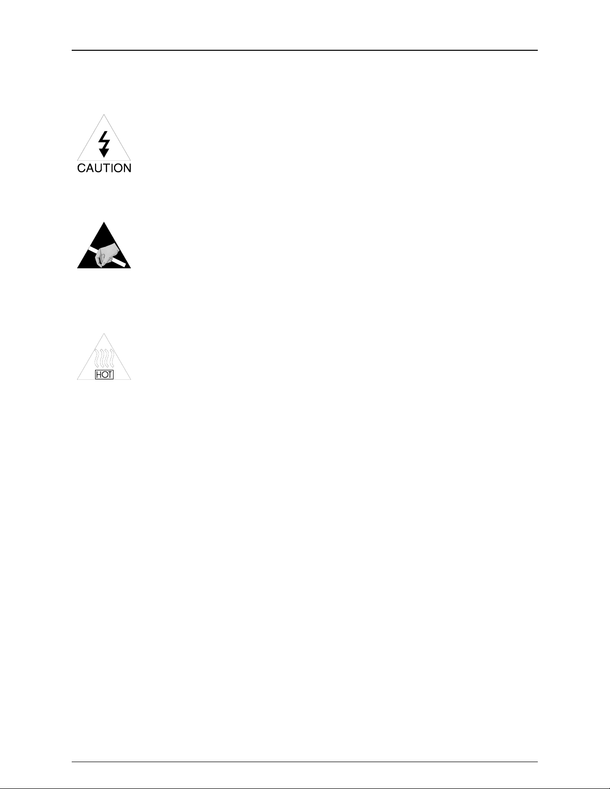
Words of Caution:
High Voltage
Use caution when servicing. When servicing the unit, potentially
dangerous high voltage levels are exposed. Disconnect the
power cord whenever possible to avoid electric shock.
Static Electricity (ESD)
Adhere to standard ESD practices at all times when servicing this
equipment. Many of the electronic devices in this equipment are
static sensitive, and may suffer catastrophic or latent failure if
handled improperly.
Heat
Lamps, power supplies, and heat sinks may emit extreme
amounts of heat during and after operation. Approach and
handle these and other potentially hot components with caution.
Finished Parts
Handle all finished parts with care. The finish can be easily scratched or
damaged from poor or improper handling.
Light Source/Illuminator Service Manual Page 10
Page 11

Section 2 Service
Performance Checks
The following performance checks will help you (1) determine whether or not the system is
operating properly, and (2) isolates a problem, if there is one.
System Set Up
Make sure the system is connected as follows:
1. Be sure that power is being provided by the wall outlet.
2. Be sure that the Lamp is installed properly.
3. Be sure that the cooling fan is turning when the unit is turned on.
4. The light source should produce a bright continuous white light with no
flickering after it reaches the steady state (approx. 15-20 Sec).
If any of these conditions do not occur, see the troubleshooting section.
Calibrations
Not Applicable
Light Source/Illuminator Service Manual Page 11
Page 12

Problem Solving
Troubleshooting
Experience shows that many service calls are due to improper operator technique and poor
connections. Before taking apart the light source, make sure that setup err ors are not causing
the problem.
harness wires, connectors, and on the circuit board.
Symptom Possible Cause Procedure
When checking voltages or signals, be sure to verify signal through the
Lamp is not illumina t ed,
and the fan is running.
Lamp connector is not
connected well.
Lamp is blown.
Defective ballast
Remove lamp cover and
re-seat connector.
Verify unit functions with a
known good lamp or lamp
functions with a known
good unit.
Verify Voltage input and
output of the Ballast
board. Refer to wiring
diagram.
1KV to 2KV present at
the output during
startup.
Note: There is
Light Source/Illuminator Service Manual Page 12
Page 13

Section 3 Problem Solving
Symptom Possible Cause Procedure
Lamp not illuminat ed, fan
does not function (No
power is apparent).
Power line damaged or
disconnected.
Power is not turned "ON"
Lamp Door Interlock
switch is disengaged.
AC line fuses F1 and/or
F2 are open.
Open circuit connection.
Power supply circuit
defective.
Connect, repair, or
replace as necessary.
Turn power on.
Verify that the lamp cover
is firmly and properly in
place and that interlock
switch is functioning
properly. Verify continuity
to be sure that the switch
is working properly.
Verify and replace as
necessary.
Verify AC input through
unit to the Switching
Power Supply.
Verify DC output at J2 of
Switching Power Supply.
Light Source overheating
Other circuits loading
down power supply.
Fan Not working properly
or blocked fan ventilation
If the fuse is blown,
disconnect the plug from
J2 (Output of the
Switching Power Supply).
Replace the blown fuse,
and reapply power. Verify
DC output at J2. If no
voltage is present or fuse
is again blown, replace
Switching Power supply.
Verify correct voltages at
the input and output of the
power supply
diagram 495102).
voltages are within
specification, then replace
motor/secondary wire
harness assembly.
(See wiring
If all
Light Source/Illuminator Service Manual Page 13
Page 14

y
p
About This Section:
This section describes how to remove and replace major sub assemblies of the
49501 (Medical Version) and 40501I (Industrial Version) Solarc Light Source.
Disassembl
and Re
air
Note:
reference on the Parts List to determine the correct part number.
Refer to the "Bubble Number" on each drawing and the cross
Part
Number
106087 PHPS 6-32 X.500 495000 4
495080 PLUG, SCREW 495000 10
Description Drawing
#
Bubble
#
Start up
order Qty
20
50
Light Source/Illuminator Service Manual Page 14
Page 15

Section 4 Disassembly and Repair
Left Housing Assy Disassembly
1. Remove the tw o screw plugs:
___
through the center of the plug w ith a 1/16 drill in a pin vise
Drill
and pull straight up.
2. Remove the Bottom Housing:
___
Loosen
thumb screw on the back of the unit and slide the
assembly towards the back of the unit.
3. Lamp Replacement Label:
___
off Label and discard.
Peel
4 Fan Guard:
___
Unscrew
the two screws on the left side directly over the AC
Power inlet that hold the fan guard in place. Only remove these
two screws.
5. Light Attenuator Assembly:
___
Unscrew
the two screws that hold Light Attenuator Control
Assembly, and remove the pan head screw, that was under the
attenuator control, from the left housing.
6. Left Housing Assembly:
___
Unscrew
the two side screws that hold the right and left
housings together. The left hous ing will now come off. Make sure
to hold the switch and t he AC power inlet down.
Light Source/Illuminator Service Manual Page 15
Page 16

Section 4 Disassembly and Repair
Ballast Board Replacement
1. Lamp:
___
Remove
the lamp from the lamp holder, and disconnect the
lamp socket.
2. Wire Tie:
___
the tie wrap that holds the black and white wires t hat lead
Cut
to the ballast board and lift the metal chassis off t o one side.
3. Ballast PCB:
___
Unscrew
board in place. Lift the board up and
the four Phillips head screws that hold the ballast
unplug
secondary wire
harness connector from the ballast board.
4. Lamp Wires:
___
Desolder
the Black and White wires from the ballast board.
5. Reassembly:
___
Reassemble
the wires under the chassis plate. The chassis plate should be
between the right housing and the insulator. Be sure to place the
ballast board insulator in its original position.
Power Supply Replacement
1. Insulator Sheet:
___
out insulator along side the PCB.
Pull
2. Wire Harness:
___
Unplug
PCB. It is the plug closest to t he fan.
___
Unplug
ground wire from the power supply board.
in reverse order taking care to not pinch any of
the secondary wire harness from the power supply
the primary wire connector and the green/yellow
3. Reassembly:
___
Reassemble
back into its original position.
supply board is
Light Source/Illuminator Service Manual Page 16
in reverse order. Be sure to put the insulator
that the new power
seated
Make sure
into the right housing.
Page 17

Section 4 Disassembly and Repair
Fan / Secondary Wire Harness Replacement
The fan comes as part of the secondary wire harness assembly; therefore, the
*
entire secondary wire harness assembly must be replaced.
1. Power Supply PCB:
___
Remove
the power supply board and the ballast board as
described in earlier in section 4 of this document. Do Not desolder
the black and white wires from the ballast board as described in
the ballast board section .
2. Fan/Fan Guard:
___
Unscrew
the remaining two screws that hold the fan to the
right housing. Taking care to remember how the ground wire is
connected and routed.
3. Wire Tie:
___
the w ire tie that holds the secondary wiring harness to t he
Cut
Black & White wires leading from the ballast board.
4. Ground Wire:
___
Unscrew
11/32 nut driver, and lift off the top two ring terminals. See detail
"A"of drawing 495072 for proper assembly of ground wires to the
chassis ground stud.
5. Thermal Cut Off:
___
Loosen
lamp holder assembly, and remove the sensor.
6. Harness:
___
Remove
7. Reassembly:
___
Reassemble
thermal compound
of the new temperature sensor before it is installed. See detail
"A"of drawing 495072 for
chassis ground stud.
grommets are positioned properly.
the top nut on the chassis ground stud, using an
the screw that holds the temperature sensor to the
the Secondary Wiring Harness assembly.
in reverse order.
(Note)
(M11047) needs to be
proper assembly of ground wires
Make sure
that the thermal cut out wire
A small amount of
applied to
the flat side
to the
Light Source/Illuminator Service Manual Page 17
Page 18

Section 4 Disassembly and Repair
Lamp Cover Safety Interlock Switch:
1. Safety Switch Assy:
___
Unscrew
the two Phillips head screws that hold the switch
assembly to the chassis. K eep the outside insulators.
2. Primary Wires:
___
Disconnect
the primary w ires from the switch, and remove the
switch.
3. Reassembly:
___
Reassemble
in reverse order. Make sure to reinstall the two
insulators that were removed in step #1. Refer to wiring diagram
for wiring of the switch.
Power Switch Replacement
1. Left Housing:
___
Remove
left housing assembly as described in the left
housing disassembly section.
2. Power Switch removal:
___
Unplug
remove
the four quick connect terminals from the switch and
defective swit ch.
3. Power Switch replacement:
___
Reassemble
the switch to the four quick connect terminals.
The switch should be set into the right housing w ith the "0" closest
to the internal chassis plate.
Light Source/Illuminator Service Manual Page 18
Page 19

Section 4 Disassembly and Repair
Replacement of the Primary Wiring Harness
1. Left Housing:
___
Remove
left housing assembly as described earlier in sect. 4.
2. Wire Ties:
___
the two wire ties that hold the harness to the internal
Cut
chassis plate.
3. Ground Wire:
___
Unscrew
11/32 nut driver, and
the two nuts on the chassis ground lug using an
remove
the primary ground wire.
4. Removal of the Interlock Switch:
___
Unscrew
the two Phillips head screws that hold the interlock
safety sw itch assembly to the chassis. Keep the out side insulators.
5. Removal of the defective wiring harness:
___
Pull
off the quick connect terminals that attach the defective
wiring harness to the power switch and to the interlock safety
switch, Remov e t he defective wiring harness.
6. Reassembly of the primary wire harness assembly:
___
Reassemble
in reverse order. Refer to wiring diagram for
wire connections.
Light Source/Illuminator Service Manual Page 19
Page 20

Maintenance
Preventative Maintenance
The purpose of preventative maintenance is to pro-actively reduce or eliminate future problems.
Keeping the Solarc Light Source in good operating condition ensures that it will perform reliably and
safely. Every six to twelve months, you should:
* Check power cable for wear.
* Ensure that, during use, the light source receives adequate ventilation.
* Ensure that the ball detent is still functioning properly.
Visual Inspection
Check for anything out of the ordinary. For instance:
- Does the light source make too much noise?
- Are there any loose parts inside the box?
- Is the power switch working properly?
- Do all components connect/disconnect easily?
- Are the ventilation holes free of obstructions?
CLEANING
Refer to Operating Manual, Welch Allyn Part Number 495003.
Light Source/Illuminator Service Manual Page 20
Page 21

Section 5 Maintenance
Check Ground Continuity
1. Disconnect the power cord from the Solarc Light Source.
2. Verify the impedance between the ground pin of the IEC detachable gr ound cord and the thumb
screw meets the requirements as outlined on drawing A03387 in Appendix. A).
Measuring Leakage Current
To check the Chassis Leakage Current:
1. Connect the light source to a leakage tester (refer to figure 5-1), and measure leakage current
on leakage meter. Ensure that leakage is less than 100 microamperes.
2. Open ground line, and ensure leakage current is less than 100 microamperes.
3. Reverse line polarity, and ensure that leakage current is less than 100 microamperes.
4. With reversed polarity, open ground line and ensure leakage is less than 100 microamperes.
CAUTION: The meter must be suitably insulated and
capable of withstanding the power line voltage.
Light Source/Illuminator Service Manual Page 21
Page 22

Section 5 Maintenance
LEAKAGE CURRENT TEST SET-UP
When the light source is used in conjunction with other accessories, it may be necessary to measure
the leakage current level of the entire set-up. A typical system setup is shown in Figure 5-1. Using a
standard leakage tester, this set-up will allow the overall sy stem leakage current to be measured. If this
value exceeds 100 microamps (or whatev er the maxi mum req uirements ar e for a particular region), an
isolation transformer should be used.
Figure 5-1: Typical Current Leakage Test Set-Up
Light Source/Illuminator Service Manual Page 22
Page 23

Section 5 Maintenance
FUSE REPLACEMENT
1. Turn the power switch OFF and disconnect the power cord from the light source.
2. Open fuse drawer located as part of the power cord receptacle.
3. Remove fuse by pulling it out firmly.
4. Check fuse condition. Replace if blown. Replacement fuse:
250V, 1.0 Amps. 5 x 20mm , Slow-Blow.
unqualified fuse may fail prematurely.
Use WA fuse only! An
5. T h is system has two fuses. Be certain to check the condition
of both fuses.
Fuse Replacement Figure 5-2
LAMP REPLACEMENT
Refer to users manual 495002 for full detail.
1. Turn the power switch OFF and disconnect the power cord from the light source.
2. Wait a minimum of 5 minutes to allow the lamp to cool.
3. Remove the lamp cover on the bottom of the Light Source by unscrewing the thumb screw on
the back of the light source.
NOTE: Removing the cover will automatically cut off power to the Light Source.
4. Slide black connector off the lamp.
5. Remove the lamp assembly by pulling against the spring action and pulling up.
6. Acquire new replacement lamp assembly.
7. Reseat the new lamp assembly. Be sure that the pin on the lamp is properly seated into the
slot on the lamp bracket.
8. Slide black connector on to lamp.
9. Secure lamp cover.
10. Reconnect system to verify lamp operation and power interlock switch is closed.
Light Source/Illuminator Service Manual Page 23
Page 24

Introduction
Theory of Operation
Model # 49501 is a
medical instruments. This model has a built in Infrared filter to limit the heat generated by the
light. It also has an external ferrite bead built into the power cord to meet Electromagnetic
Interference (EMI) requirements. This light source should only be used by qualified medical
personnel.
Model HLS-24-0 is an industrial illuminator which can be used in many industrial applications.
The HL S-24-0 is also known at Welch Allyn as a 49501I (The I indicates that the unit is for
industrial use only). This instrument is identical to the 49501 medical light source with the
deletion of the Infrared filter and the Ferrite bead.
Start up Routine (Lamp Ignition)
Upon turning the power switch to the "ON" position lamp ballast will ignite the lamps for an
approximate warm-up phase of 15 seconds. Once this warm-up phase is complete, the the lamps
will be warmed up, and the system will be ready for use.
Note: The fiber bundle must be in place to stabilize light output. Do not toggle the power switch
ON and OFF . Doing so will dramatically shorten lamp life. The lamp will not restart for 5-10
Seconds after power down.
medical light source
which is used in conjunction with several Welch Allyn
Light Source/Illuminator Service Manual Page 24
Page 25

Section 6 Theory of Operation
Power Supply
UNIVERSAL INPUT, SWITCHING AC TO DC MEDICAL GRADE POWE R SUPPLY
The power supply accepts an input voltage of 100-240 VAC, 50-60 Hz, single phase. The primary
circuit provides adequate control of leakage current, which is limited to 35 microamperes maximum.
The primary side of the power supply rectifies the AC vol tage and converts it to a high voltage DC lev el.
This DC vol tage is connected to the i solation transformer through a sw itching dev ice, typical ly a mosfet.
The mosfet is triggered by a high frequency clock circuit, typically at a 30-50 KHz rate. The
secondary side of this transformer provides isolation between primary and secondary circuits. The
secondary voltage i s rectified and filtered to pr ovide a + 15 VDC output vol tage at 5.3 amps. The output
voltage is regulated to 2%, with peak-to-peak noise of 150mV. The output is fully protected against
short circuit and output overload. Short circuit protection is a cycling type power limit with automatic
recovery after fault.
Ballast Board
The ballast board is a power supply used to operate the 24 watt Welch Allyn miniature arc lamp. The
nature of arc lamps require a ballast which limits the current, and therefore the power, in the lamp.
There are three states of the operation of the ballast: ignition, warm-up, and steady state. In ignition
the ballast provides the lamp with a train of ignition pulses between 6 and 7 kV. Once the lamp is
ignited the ballast conducts current at a very low impedance, which constitutes the warm-up phase.
Once it warms up, the impedance changes to a higher steady state value.
Light Source/Illuminator Service Manual Page 25
Page 26

Appendix A
Light Source/Illuminator Service Manual Page 26
Page 27

Parts List / Recommended Inventory
Part No. Description Drawing # Bubble # Rec. Inv.
106100-8 PHPS 6-32 X .63 LG 495000 1 20
106102-2 FHPS 4-40 X .375 LG 495000 3 20
106100-13 PHPS 6-32 X.500 495000 4 20
495059 LAMP REPLACEMENT LABEL 495000 5 25
495063-1 HOUSING, LEFT 495000 9 1
495080 PLUG, SCREW 495000 10 50
095100 LAMP, 24W MINIATURE ARC 495000 11 5
106132-5 4-40 X .750 PH TR MS SS 495000 14 10
495086-501 ACMI ATTENUATOR ASSY 495000 15 0
495055-502 MOUNTING BASE ASSY 495000 16 2
495061-1 LABEL, ETL W/CE 495000 17 5
495062-0 LABEL MODEL NUMBER 495000 18 5
495111 DIELECTRIC FILTER 495000 19 5
328043-1 RETAINING RING-LENS 495000 20 5
106106-2 #4 INTRNL TOOTH LKWSHR 495064 1 20
106103-27 FLAT WASHER 495064 2 20
790043 4-40 HEX NUT 495064 4 10
106102-2 FHPS 4-40 X .375 LG 495064 6 20
106124-13 #2 X 1/4 SCREW-PLASTITE 495064 7 20
495067 FAN GUARD 495064 8 0
495068 BALLAST 24W UNREGULATED 495064 10 5
880031 POWER SUPPLY 40 WATT 495064 11 5
495069-1 HOUSING, RIGHT 495064 15 1
495070 INSULATOR, POWER SUPPLY 495064 16 5
495071 INSULATOR, BALLAST 495064 17 5
Light Source/Illuminator Service Manual Page 27
Page 28

Parts List / Recommended Inventory
Part No. Description Drawing # Bubble # Rec. Inv
495066 LAMP HOLDER 495064 22 0
106132-3 4-40 X 1" PH TR MS SS 495064 23 10
106132-5 4-40 X .750 PH TR MS SS 495064 24 10
M31426 .032DIA ENERGIZED ROSIN S 495064 25 1
106113-6 #4-40 SOCKET SET SCREW 495064 27 20
495065 LAMP SPRING 495064 28 0
M30373 LOCTITE 425 ASSURE THDLOC 495064 30 1
106132-4 6-32 X .3125 TRUSS HEAD
SCREW
495076 CHASSIS, INTERNAL 495072 1 0
455508 LABEL, PROTECTIVE EARTH
Ground
495073 GROMMET .126 ID X.06 X.25 495072 3 10
495064 31 10
495072 2 15
.
495077 PRIMARY WIRE HARNESS 495072 5 1
747187 #8-32 HEX-NUT 495072 8 10
483412 #8 EXTERNAL LOCKWASHER 495072 9 4
761077-1 TIE WRAP 495072 10 50
495074 INSULATING PLATE 495072 12 0
451534 SCREW PHP #4-40 X1.0 495072 13 20
495075 BALLAST SIDE CONN ASSY C1 495072 15 5
495078-1 SECONDARY WIRE HARNESS 495078 NA 1
488307-9 FUSE NA NA 20
495079-501 BOTTOM HOUSING ASSY NA NA 1
Light Source/Illuminator Service Manual Page 28
Page 29

Page 30

Page 31

Page 32

Page 33

Page 34

 Loading...