

Page 1
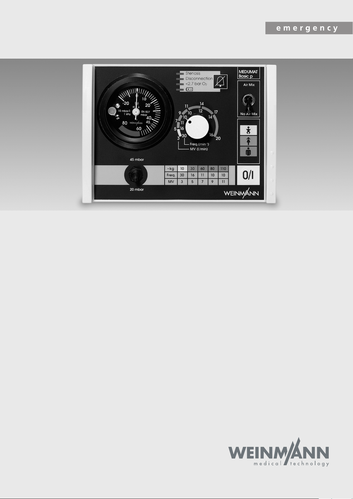
MEDUMAT Basic
Ventilator
MEDUMAT Basic
Ventilator
Servicing and repair instructions
WM 22600
p
WM 22650
Page 2

Contents
Introduction
1.
Overview
1.1
2.
Description of ventilator
2.1
2.2
2.3
3.
Final Check
3.1
3.2
3.3
3.4
3.5
3.6
3.7
3.8
3.9
3.10
3.11
3.12
3.13
3.14
3.15
4.
Servicing
4.1
4.2
4.3
4.4
4.5
5.
Troubleshooting
. . . . . . . . . . . . . . . . . . . . . . . . . .
. . . . . . . . . . . . . . . . . . . . . . . . . . .
Symbols used on the ventilator
Uses
. . . . . . . . . . . . . . . . . . . . . . . . .
Ventilation function
Patient valve
. . . . . . . . . . . . . . . . . . . . . . . . . .
Test resources required
Preparations for final check
Entering device data
Testing for leaks and checking pressure
reading
Device self-test after switching on
Functional check on alarms
Functional check on frequency setting
Functional check on
at 4.5 bar delivery pressure and
10 mbar counterpressure
Checking oxygen concentration
Functional check on pressure limit
Functional check on exhaust valve
without patient valve
Check the breath volume
Checking equipment and accessories
(system components)
Checking external condition
Documentation
Intervals and Scope
Batteries and fuses
Adjusting the pressure gauge
Storage
Disposal
. . . . . . . . . . . . . . . . . . . . . .
. . . . . . . . . . . . . . . . . . . . . . . . . . .
. . . . . . . . . . . . . . . . . . . . .
. . . . . . . . . . . . . . . . . . . . .
. . . . . . . . . . . . . . . . . . . . . .
. . . . . . . .
. . . . . . . . . . . . . . . . .
. . . . . . . . . . . . . . .
. . . . . . . . . . . . . . . . . . .
. . . . . . . . . . . .
. . . . . . . . . .
. . . . . . . . . . . . . .
. . . . .
. . . . . . . . .
. .
tidal volume
. . . . . . . . . .
. . . . . .
. . . .
. . . . . . . . . . . . .
. . . . . . . . . .
. . . . . . . . . . . . .
. . . . . . . .
. . . . . . . . . . . . . . . . .
. . . . . . . . . . . . . .
. . . . . . . . . . . . . .
. . . . . . .
10
10
11
11
12
13
13
13
13
14
14
15
15
16
16
17
17
18
3
4
5
6
6
6
7
8
8
9
9
9
6.
Repair information and repair instructions
6.1
General
6.2
Replacing the sieve in the compressed
gas connection
6.3
Changing the foam insert in the
pressure relief valve outlet
6.4
Opening the
6.5
Closing the
6.6
Changing the batteries
6.7
Replacing the fuse
6.8
Replacing ventilation control knob
6.9
Calibration after removal of PCB,
ventilation control knob 5 and/or
pneumatic block
6.10
Replacing the alarm signalling device
6.11
Replacing two-way switch for maximum
ventilation pressure (
Basic p Basic p only)
6.12
Replacing the circuit board. . . . . . . . . 29
6.13 Replacing the pressure gauge . . . . . . . 31
6.14 Replacing the pneumatic block . . . . . . 32
6.15 Replacing the pneumatic block with
angled outlet . . . . . . . . . . . . . . . . . . 34
6.16 Replace 3/2 solenoid valve . . . . . . . . 37
6.17 Changing the Air Mix/
7. Spare parts . . . . . . . . . . . . . . . . . . . . . . . . . 47
8. Tools and test equipment . . . . . . . . . . . . . . . 51
9. Technical data . . . . . . . . . . . . . . . . . . . . . . . 53
10. Technical Changes . . . . . . . . . . . . . . . . . . . . 56
11. Repair and inspection log. . . . . . . . . . . . . . . 57
No Air Mix switch . . . . . . . . . . . . . . 38
6.18 Replace upper part of housing/
control panel . . . . . . . . . . . . . . . . . . 39
6.19 Replacing the housing base section . . . 45
6.20 Upgrading ventilation tube . . . . . . . . . 46
7.1 List of spare parts . . . . . . . . . . . . . . . 47
7.2 Maintenance set. . . . . . . . . . . . . . . . 49
8.1 General tools. . . . . . . . . . . . . . . . . . 51
8.2 Special tools . . . . . . . . . . . . . . . . . . 51
8.3 Test equipment . . . . . . . . . . . . . . . . . 52
9.1 Pneumatics . . . . . . . . . . . . . . . . . . . 54
9.2 O2 content when using Air Mix. . . . . . 55
. . . . . . . . . . . . . . . . . . . . .
. . . . . . . . . . . . . . . .
. . . . . . . . . .
device
. . . . . . . . . . . . .
device
. . . . . . . . . . . . . .
. . . . . . . . . . .
. . . . . . . . . . . . . . .
. . . . . . . . . . . . . . . .
MEDUMAT Basic /
. . . . . . . . . . . . .
. .
. . . .
. .
21
21
21
22
22
23
23
24
24
25
27
28
© Copyright Weinmann GmbH & Co. KG.
The content and presentation are copyright protected and may only be used by authorised Weinmann Service Partners in the
course of their service operations. The content must not be reproduced or passed on to third parties. The complete documents
must be returned on termination of the cooperation with Weinmann.
2
Page 3

Introduction
For decades, Weinmann has developed, manufactured and distributed equipment for emergency
medicine, oxygen therapy and inhalation therapy.
In 1972, Weinmann introduced the first
MEDUMAT emergency ventilator to the market.
MEDUMAT emergency ventilators are automatic
resuscitators. They are used for controlled respiration in emergency medicine, e.g. in the event of
acute ventilatory disorders, and for secondary obstructions.
The new generation of equipment, which was
especially developed to meet the requirements of
users, offers users and patients an enhanced level
of safety. An intelligent alarm system monitors the
patient's breathing and notifies the user of any malfunctions. Hence, this technology offers even greater safety and reliability during respiration.
The aim of these service and repair instructions is
to familiarise you, as a knowledgeable expert, with
the MEDUMAT in terms of function, technology
and repairs. In conjunction with the training you
have already received from Weinmann, you are
now a "trained, qualified expert" and are able to
instruct your clients correctly, rectify faults yourself,
and perform the functional checks described in the
instructions for use, as well as conduct any repairs
which may be necessary, as outlined in these service and repair instructions.
In the event of a guarantee claim, MEDUMAT should
be returned to Weinmann.
To enable us to process any guarantee or goodwill
claims, please return the consumer's proof of
purchase (invoice) together with the device.
Repairs and maintenance work must be carried out
only by Weinmann or by knowledgeable experts.
You are responsible for all repairs performed by
yourself and the warranty thereof!
Only original Weinmann spare parts should be used
for repair purposes.
Please remember:
Your customer trusts you and relies on your expertise, just as you rely on Weinmann.
Note:
The following information can be found in the description and operating instructions for MEDUMAT:
• Safety instructions
• Mounting with the wall bracket STATION MEDUMAT,
Mounting of accessories
• Operation
• Hygienic preparation
• Functional check
3
Page 4
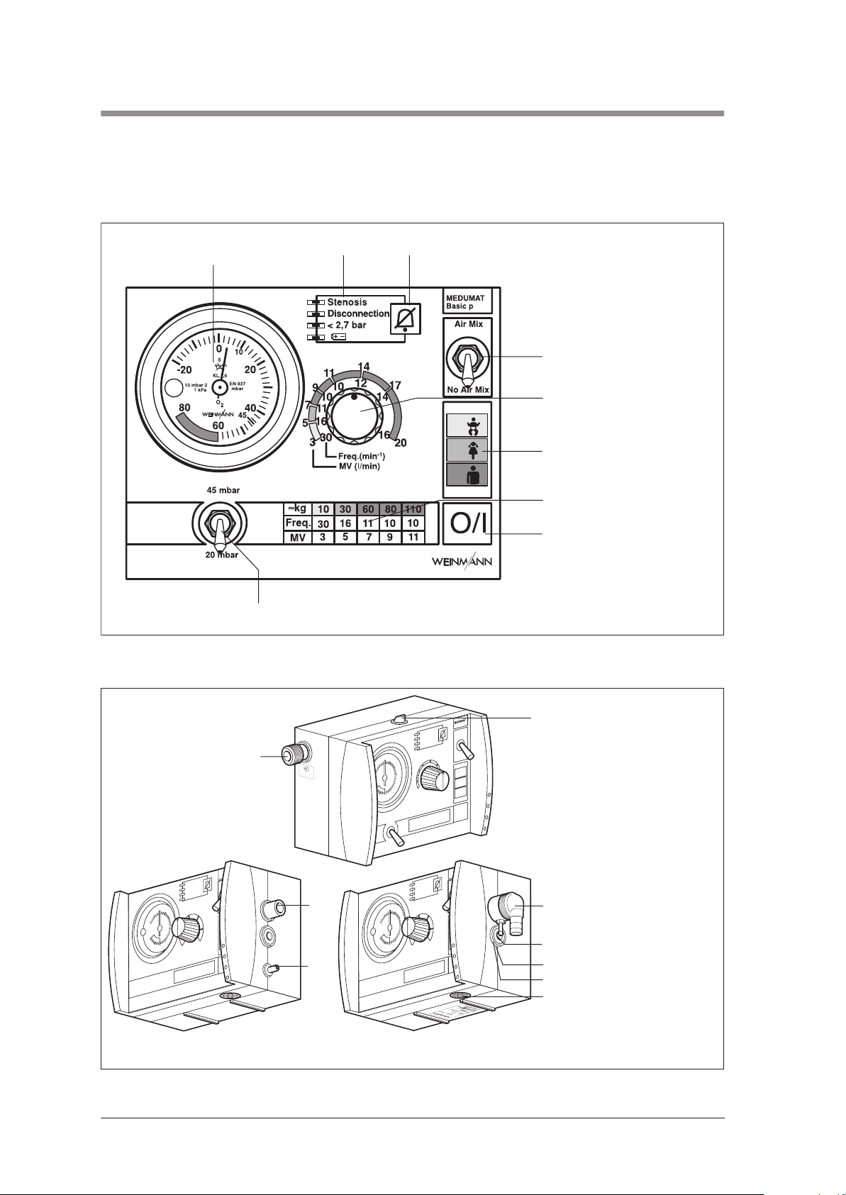
1. Overview
Control panel MEDUMAT Basic, Basic p
1 Ventilation pressure gauge
3 Alarm mute button2 Alarm panel
(Manometer)
9 Tumbler switch for setting max.
ventilation pressure (Basic p only)
4 Air Mix/No Air Mix switch
5 Minute volume regulator
6 Colour code
7 Recommendations for ventilation
settings
8 ON/OFF switch
MEDUMAT Basic, Basic p connections
10 Pressure gas connection
®
T
A
M
U
D
E
M
ic
s
a
B
12
O/I
up to appliance no.: Basic 1019
Basic p 1399
13
from appliance no.: Basic 1020
p
c
i
s
a
B
/I
O
®
T
A
M
U
D
E
M
ic
s
a
B
O/I
:
:
N
S
:
p
y
T
Basic p 1400
11 Locking latch for STATION
MEDUMAT wall bracket
12 Connection for ventilation hose
13 Pressure gauge hose connection
14 Relief valve
15 Dust cover
16 Mixed air filter
4 Overview
Page 5
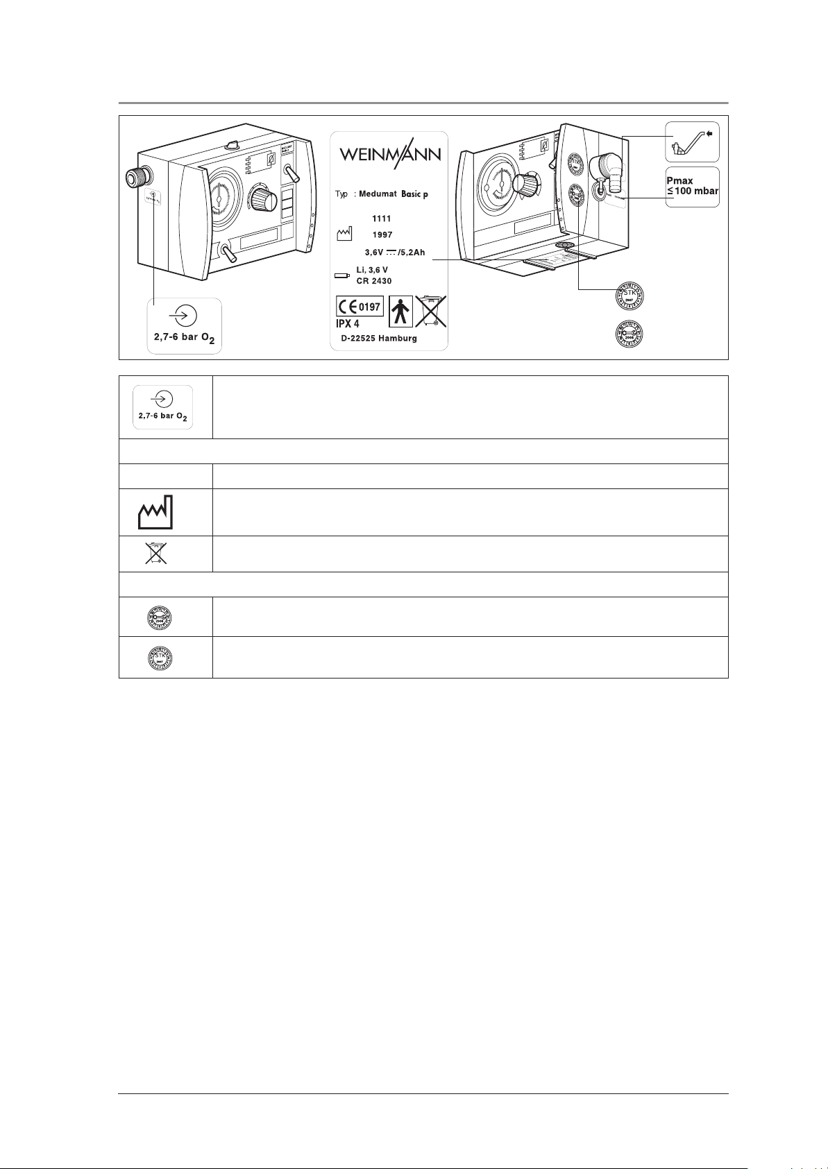
1.1 Symbols used on the ventilator
SN
SN :
O/I
:
Inlet 2,7 - 6 bar O2.
MEDUMAT Basic / Basic p device information plate
Serial number of device
Year of manufacture
Do not dispose of device in domestic waste.
Safety check and servicing label
Servicing label: indicates when the next service is due.
O/I
:
:
:
p
y
T
N
S
Safety check label (in Germany only): marks when the next safety check as per §6 of the
German law relating to users of medical devices is required.
Overview 5
Page 6
2. Description of ventilator
2.1 Uses
MEDUMAT Basic / Basic p is an automatic (short-term) ventilator.
You can use MEDUMAT Basic / Basic p:
• to revive patients at the site of an emergency
• on a longer term basis in more protracted
emergencies, e.g. fires.
You can use MEDUMAT Basic / Basic p whilst
transporting patients:
• between the various rooms and departments
of a hospital;
• between the hospital and other premises;
• in emergencies;
• when transport over a considerable distance is
planned.
2.2 Ventilation function
MEDUMAT Basic / Basic p operates within a pressure range of 2.7 to 6 bar and at a flow rate of not
less than 70 l/min O2. It has a built-in power
pack.
The gas used for ventilation is highly compressed
medical oxygen, which is reduced to the required
operating pressure by a two-stage external pressure reducer. The oxygen supply is fed in at input
valve 10.
MEDUMAT Basic / Basic p:
• is designed to provide controlled ventilation to
persons of 10 kg body weight or more;
• is used to treat respiratory arrest;
• can be preset to parameters that ensure evenly
balanced ventilation provided that the selected
maximum ventilation pressure P
is not ex-
max
ceeded.
• can be supplied with additional modules for
aspiration and oxygen inhalation. (N.B.
MEDUMAT Basic / Basic p cannot be used
as a ventilator simultaneously with these modules)
p
c
i
s
a
B
10
/I
O
The continuously adjustable ventilation settings and
the inspiration/expiration ratio of1:1.67 are regulated internally by electronic control processes.
The gas for inspiration flows along the hose and
through the patient valve and either the mask or the
tracheal tube into the patient’s airways. The patient
valve is fitted with a lip membrane that enables expired gas to be conducted away through the expiration tube.
6 Description of ventilator
Page 7
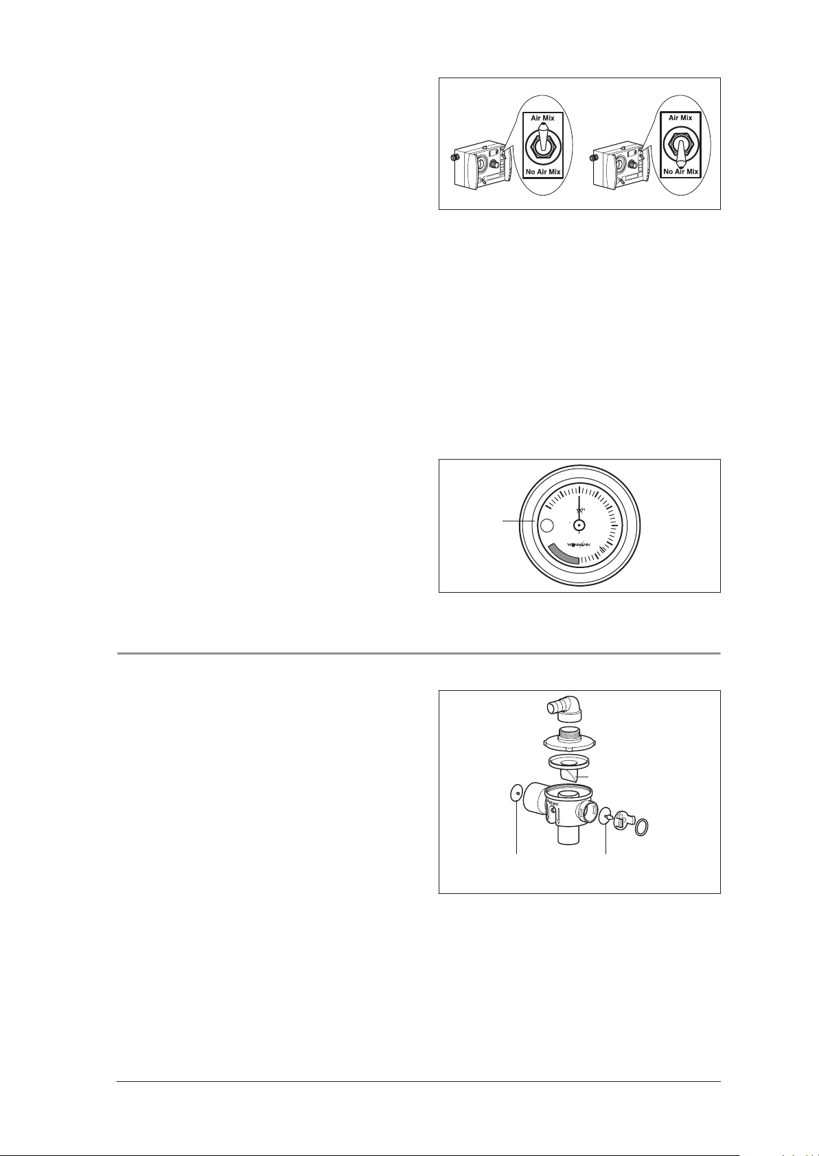
At the normal Air Mix setting, atmospheric air is admixed to give an O2-concentration of between
55% and 85% at 10 mbar ventilation pressure
(see “9.2 O2 content when using Air Mix“ on
page 55).
In certain indications and in cases where the surrounding atmosphere is contaminated, you can
switch to No Air Mix and ventilate with pure oxygen.
The injector unit is switched off when switching
from Air Mix to No Air Mix. This increases minute
volume which can result in the set pressure limit being exceeded and a stenosis alarm (Stenosis) being
triggered. In this case, set minute volume correspondingly lower.
In the opposite instance, in other words when
switching from No Air Mix to Air Mix, the injector
unit is switched on. This reduces minute volume
which can lead to the set pressure limit being un-
dershot. In this case, set minute volume correspond-
ingly higher.
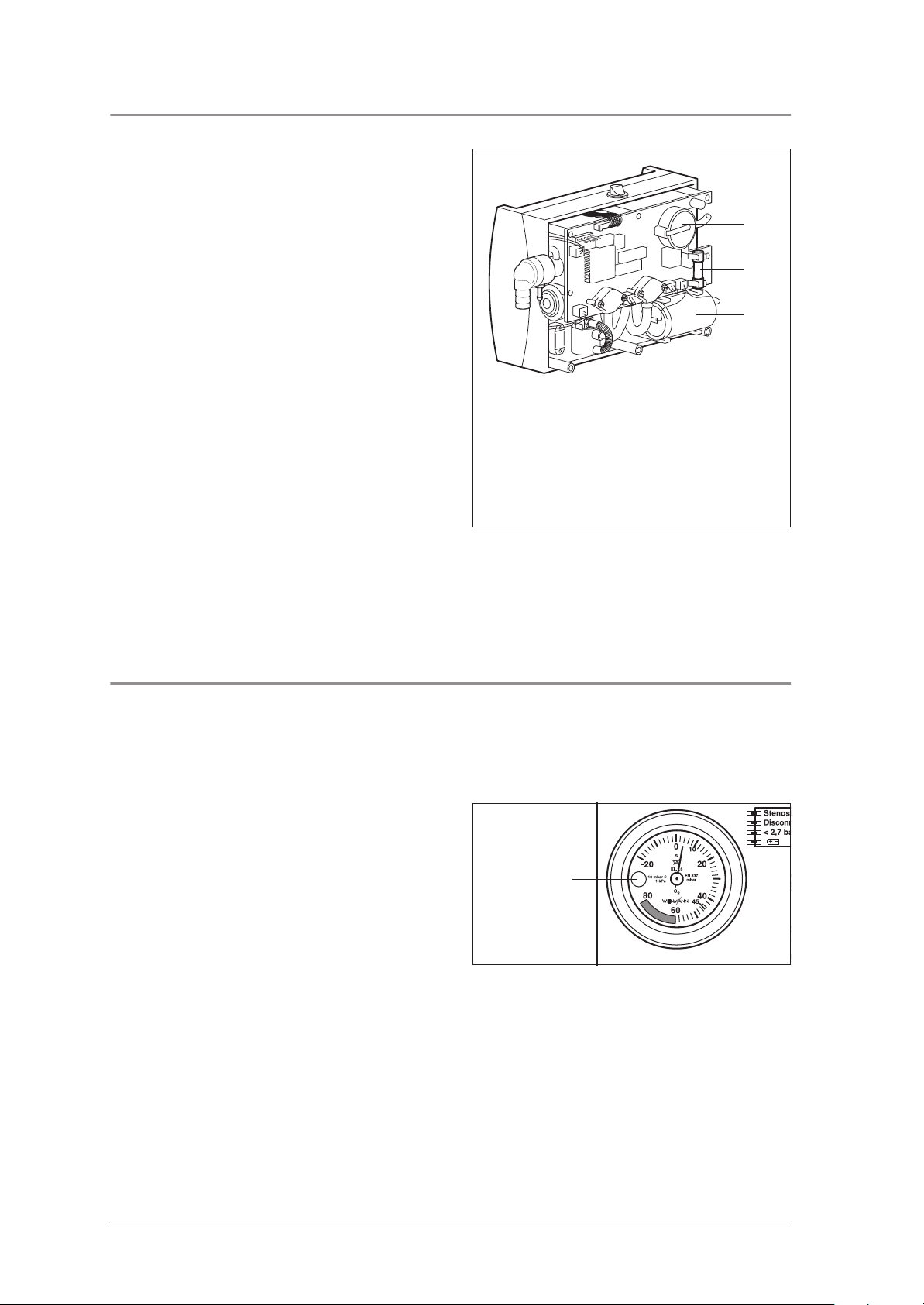
You can check the course of the ventilation on pressure gauge 1.
/I
O
0
10
S
1
-20
80
10 mbar =
1 kPa
20
KL.1,6
EN 837
mbar
O
2
40
45
60
2.3 Patient valve
The gas for inspiration is channelled into the patient’s airways through the patient valve.
This valve is designed to enable spontaneous breathing
in case of equipment failure.
Diaphragm for
exspirations arm
Lip membrane
Diaphragm for
spontaneous
breathing arm
Description of ventilator 7
Page 8

3. Final Check
After any repair and maintenance work, the device
must be subjected to the following final check in
accordance with the Test Instructions WM 22671
and Test Record.
Note:
For a final check on the MEDUMAT Basic /
Basic p you must connect the respiration tube and
the patient valve.
If the final check reveals faults or deviations from
the specified values, you must not use the
We recommend you to keep the following parts in
stock:
• Replacement seals for device connections;
• Replacement dust filter;
• Lip diaphragm for patient valve;
• Diaphragm for spontaneous breathing leg;
• Diaphragm for expiration leg;
• O–Ring 1145/118.
MEDUMAT Basic / Basic p.
3.1 Test resources required
• Flowmeter, PF 300 (imtmedical), RT 200 (Timeter), EKU VIP (EKU Elektronik) or comparable testing
device
• Functional check test set WM 15335
• Adjustable orifice, e.g. ball valve, internal diameter ≥ 10 mm
• Oxygen concentration measuring device, 0 – 100 % ± 1 %,
e.g. Type Oxycontrol WM 13550
• Set: hose with injector WM 15359
• Pressure gauge 0 - 13 bar, class 1.6
• Pressure gauge 0 - 160 mbar, class 1.6
• Set, supply test Medumat / Modules WM 15440
Default settings for flow meter PF300
Settings Values
Default settings:
– Type of gas
– Gas standardization
Trigger settings:
– Type of ventilation
– Source
– Start
– End
– Delay
– Base flow rate
Units and measured values:
– P high
– P diff
– Rate
– Vti
– O
2
Air/02 auto
STP
Adult
Internal HF
Flow rate ≥ 3.0 l/min
Flow rate ≤ 3,0 l/min
60 ms
disabled
bar
mbar
1/min or b/min
ml
%
If you have a comparable testing device, contact WEINMANN’s Technical Support department to have the
setting parameters calibrated.
8 Final Check
Page 9
3.2 Preparations for final check
1. Connect MEDUMAT Basic / Basic p to pressure supply 4.5 – 6 bar of cylinder system.
2. Connect respiration tube and pressure measurement tube to MEDUMAT Basic / Basic p.
3. Set MEDUMAT Basic / Basic p with switch in position No Air Mix to Freq. = 30 min-1, MV = 3 l/min
and P
= 45 mbar.
max
4. Start check.
3.3 Entering device data
• Enter the device number and date of manufacture in the Test Record.
3.4 Testing for leaks and checking pressure reading
3.4.1 Testing for leaks on the inlet side
• With device switched off, apply pressure of 6 bar to inlet side and shut off outlet pressure.
• Set lever to No Air Mix.
Requirement: The pressure drop must be less than 0.2 bar/min.
• Set lever to Air Mix.
Requirement: The pressure drop must be less than 0.2 bar/min.
3.4.2 Testing for leaks in pressure measurement segment
• Apply pressure of 60 mbar to pressure measurement segment of MEDUMAT Basic / Basic p.
• During the measurement, a traction force of approx. 3 N must be applied manually to the elbow outlet.
Requirement: The pressure drop must be less than 2 mbar/min.
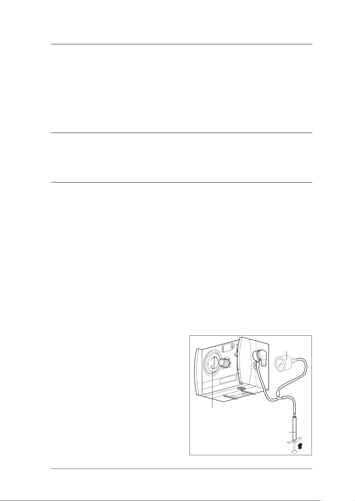
3.4.3 Checking pressure reading
®
T
A
M
U
D
E
1. Attach T-connector with injector (WM 15359)
to pressure measurement connection 13.
2. Connect test pressure gauge 0 - 100 mbar or
Timeter to free end of T-connector (pressure
gauge/volumetric flowmeter not supplied with
device).
3. Use injector to create a pressure of 55 mbar
as shown on the test pressure gauge.
Requirement: Respiration pressure reading must not
deviate from set value by more than ≤≤≤≤ 1.5 mbar.
Pressure gauge
M
c
i
s
a
B
/I
O
:
:
N
S
:
p
y
T
Test pressure
gauge
Injector
Final Check 9
Page 10

3.5 Device self-test after switching on
1. Apply approx. 4.5 bar to the inlet.
2. Switch on MEDUMAT Basic / Basic p at pushbutton 8 O/I.
Requirement: The self-test is activated: all 4 LEDs light up together and a brief signal tone sounds.
3.6 Functional check on alarms
3.6.1 Stenosis alarm check up to appliance no.: Basic 1019; Basic p 1399
• Set MEDUMAT Basic / Basic p to the Air Mix setting at f = 30/min, MV = 3 l/min and
p
= 45 mbar. Close patient valve outlet.
max
Note: Over-response of needle is normal.
Requirement: The stenosis alarm must be activated after two respiration cycles.
• Set MEDUMAT Basic / Basic p to the No Air Mix setting at f = 30/min, MV = 3 l/min and
p
= 45 mbar. Close patient valve outlet.
max
Note: Over-response of needle is normal.
Requirement: The stenosis alarm must be activated after two respiration cycles.
3.6.2 Stenosis alarm check from appliance no.: Basic 1020; Basic p 1400
• Set MEDUMAT Basic / Basic p to the Air Mix setting at f = 30/min, MV = 3 l/min and
p
= 45 mbar. Close patient valve outlet.
max
Note: Over-response of needle is normal.
MEDUMAT Basic / Basic p briefly switches to expiration if the maximum ventilation pressure is exceeded, but then tries to continue inspiration in the same inspiration phase.
If the maximum ventilation pressure is exceeded for a second time during the same inspiration phase,
the unit finally switches to expiration and vents the patient tube system completely. The next inspiration
begins with the following ventilation stroke according to the frequency selected.
Requirement: The stenosis alarm must be activated after two respiration cycles.
• Set MEDUMAT Basic / Basic p to the No Air Mix setting at f = 30/min, MV = 3 l/min and
p
= 45 mbar. Close patient valve outlet.
max
Note: Over-response of needle is normal.
Requirement: The stenosis alarm must be activated after two respiration cycles.
3.6.3 Test alarm mute button
• Immediately after first alarm tone sounds, press button 3 alarm acknowledgement.
Requirement: The alarm tone must be suppressed immediately. The alarm sounds again after approx.
1 min (or immediately, if parameters are changed).
3.6.4 Disconnection alarm check
• Open patient valve outlet.
Requirement: The disconnection alarm must be activated after two respiration cycles.
3.6.5 Pressure alarm check
• Shut off pressurised gas connection of MEDUMAT Basic / Basic p (2.7 - 6.0 bar).
Requirement: The pressure alarm must be activated.
10 Final Check
Page 11
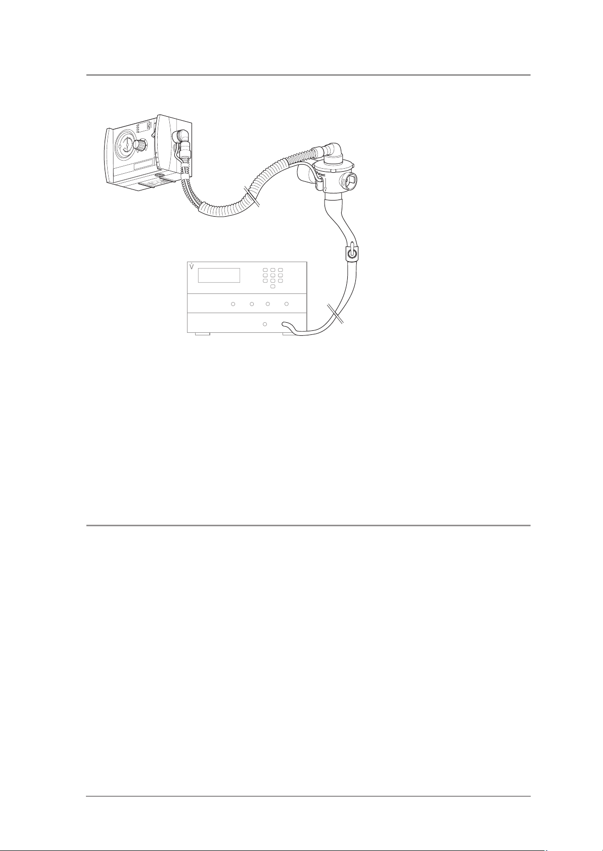
3.7 Functional check on frequency setting
Connect respiration tube to 10 mbar orifice and to volumetric flowmeter.
®
T
A
M
U
D
E
M
c
asi
B
Patient valve with
/I
O
:
:
N
S
:
p
y
T
Volumetric flowmeter
tube system
Orifice 10 mbar
open
1. Run MEDUMAT Basic / Basic p in position No Air Mix, Freq. = 16 min
Requirement: The measured frequency must be 16 ± 2 min
-1
.
2. Run MEDUMAT Basic / Basic p in position No Air Mix, Freq. = 10 min
Requirement: The measured frequency must be 10 ± 2 min
-1
.
3. Run MEDUMAT Basic / Basic p in position No Air Mix, Freq. = 30 min
Requirement: The measured frequency must be 30 ± 2 min
-1
.
-1
and MV = 20 l/min.
-1
and MV = 11 l/min.
-1
and MV = 3 l/min.
3.8 Functional check on tidal volume at 4.5 bar delivery pressure and 10 mbar counterpressure
1. Run MEDUMAT Basic / Basic p in position No Air Mix, Freq. = 16 min-1 and MV = 20 l/min.
Requirement: Tidal volume must be 1250 ± 190 ml.
Switch MEDUMAT Basic / Basic p to position Air Mix.
Requirement: Tidal volume must be 1250 ± 190 ml.
2. Run MEDUMAT Basic / Basic p in position No Air Mix, Freq. = 10 min-1 and MV = 11 l/min.
Requirement: Tidal volume must be 1100 ± 170 ml.
Switch MEDUMAT Basic / Basic p to position Air Mix.
Requirement: Tidal volume must be 1100 ± 170 ml.
Final Check 11
Page 12
3. Run MEDUMAT Basic / Basic p in position No Air Mix, Freq. = 30 min-1 and MV = 3 l/min.
Requirement: Tidal volume must be 100 ± 20 ml.
Switch MEDUMAT Basic / Basic p to position Air Mix.
Requirement: Tidal volume must be 100 ± 20 ml.
Patient valve with
tube system
®
T
A
M
U
D
E
M
c
i
s
a
B
I
/
O
Volumetric flowmeter
Orifice set to
10 mbar
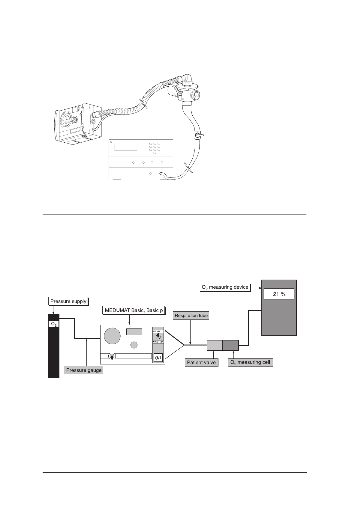
3.9 Checking oxygen concentration
1. Run MEDUMAT Basic / Basic p in position Freq. = 10 min-1 and MV = 11 l/min with 100 % O2.
2. Check O2 concentration in position No Air Mix.
Requirement: The O
concentration must be greater than 98 %.
2
3. Check O2 concentration in position Air Mix.
Requirement: The O
concentration must lie between 50 % and 65 %.
2
12 Final Check
Page 13

3.10 Functional check on pressure limit
1. Connect respiration tube to test bag.
2. Set MEDUMAT Basic / Basic p to No Air Mix, Freq. = 11 min-1 and MV = 7 l/min.
3. Applies to MEDUMAT Basic / Basic p Basic p only
Set pressure limit to 20 mbar.
Requirement: The pressure limit must respond at 20 ± 5 mbar and trigger the stenosis alarm.
4. Applies to MEDUMAT Basic / Basic p Basic and MEDUMAT Basic / Basic p Basic p
Set pressure limit to 45 mbar.
Requirement: The pressure limit must respond at 45 ± 5 mbar and trigger the stenosis alarm.
3.11 Functional check on exhaust valve without patient valve
1. Run MEDUMAT Basic / Basic p in position f = 10 min
2. Connect patient valve to device outlet with expiration outlet closed, without lip diaphragm and with test
bag.
Requirement: The test bag is completely inflated in one inspiration stroke. The respiration device can then
be heard to exhaust.
-1
and MV = 11 l/min.
3.12 Check the breath volume
See “Check the breath volume” in the description and operating instructions for MEDUMAT.
3.13 Checking equipment and accessories (system components)
• Respiration tube with patient valve undamaged and in working order
• Functional check test set in working order
• Pressure reducer in working order
• O2 cylinder within test deadline; valve in working order
• Portable system complete and in working order
• Medical products book present
• Operating instructions present
Final Check 13
Page 14

3.14 Checking external condition
• Check external condition of device.
Requirement: No mechanical damage to housing.
Device labels with operating information are legible.
Sealing sleeves are properly seated.
Pressure gauge zero reading is correct.
Connecting thread G3/8 is undamaged and functions smoothly.
All rotary knobs are self-locking against inadvertent readjustment.
3.15 Documentation
• Document points 4. to 13. in the Test Record, along with test date and tester number.
14 Final Check
Page 15

4. Servicing
N.B.
Always remember to carry out a technical safety check of the ventilator after every repair.
MEDUMAT Basic / Basic p must be serviced regularly.
We recommend having all maintenance work, servicing and repairs carried out either by the manufacturer
Weinmann or by a qualified agent expressly authorised by that company.
4.1 Intervals and Scope
Every 2 years:
Every 2 years, you must subject the device (including patient valve and tube system) to a technical safety check
and maintenance.
The servicing and inspection may also be carried out by the manufacturer Weinmann.
The following points should be observed:
• Check that the equipment is complete
• Visual check for:
– physical or mechanical damage
– correct markings on controls
– damage to all external hoses
• Replacement of worn components/
compulsory change parts (see “7.2 Maintenance set” on page 49);
• Check of system components: portable system, oxygen supply fittings, secretion suction
system, hose connections etc.
• Check test bag.
• Repeat testing of aluminium oxygen bottles
WM 1821 and WM 3621 by the Technical
Testing Association. The specified testing date
is stamped on the shoulder of the bottle.
• Final check in accordance with Test Instructions/
Test Report STK WM 22671 (see „3. Final Check“
on page 8 and see “11. Repair and inspection
log” on page 57).
Every 4 years:
• Servicing of the fittings in the oxygen supply system (e.g. pressure reducer) either by the manufacturer or
by a qualified agent expressly authorised by him.
Every 10 years:
• Repeat testing of the conventional steel or aluminium oxygen bottles by the Technical Testing Association.
The specified testing date is stamped on the shoulder of the bottle.
Servicing 15
Page 16
4.2 Batteries and fuses
MEDUMAT Basic / Basic p is fitted with two batteries which must always be changed together:
A button cell CR2430 17 supplies the electronics
with auxiliary power if the capacity of the main
battery 19 is exhausted. This means that an alarm
can still be activated in the event of sudden failure
of the main battery. The device switches to expiration.
As a general rule, the capacities of the batteries
are designed in such a way that under normal usage conditions, they do not need to be changed
during the 2-year servicing intervals. Within the
context of the prescribed 2-year servicing, the batteries are replaced completely.
We recommend that the batteries be changed
only by the manufacturer Weinmann or by authorised specialists explicity authorised by them, since
special precautions must be taken to protect the
electronics (see “6.6 Changing the batteries” on
page 23)).
17
18
19
17:Button cell for auxiliary power
18:Fuse to prevent internal short-circuiting
19:Lithium battery 3.6 V for main power to
MEDUMAT Basic / Basic p
For information on replacing the fuse, see Section
„6.7 Replacing the fuse“ on page 24.
4.3 Adjusting the pressure gauge
In the idle state, with MEDUMAT Basic / Basic p deactivated and the oxygen cylinder closed, the needle of
the pressure gauge must point precisely to “0”.
To adjust the needle, proceed as follows:
1. Carefully lever out the plastic cover of the adjusting screw.
2. Adjust the needle with the adjusting screw
using a small screwdriver.
3. Re-insert the plastic cover.
Adjusting screw
16 Servicing
Page 17

4.4 Storage
If you are not intending to use MEDUMAT Basic / Basic p for a long period, we recommend the following
storage precautions:
1. Clean and disinfect the ventilator (see
“5. Hygienic preparation” of the description
and operating instructions for MEDUMAT).
2. Store MEDUMAT Basic / Basic p in a dry
place.
4.5 Disposal
Do not dispose of the unit with domestic waste. For proper waste disposal of the equipment, please
contact an approved and certified waste disposal site for electronic goods. Ask your Environmental
Officer or town council for the address.
Important note!
Remember that the ventilator still requires servicing
at the stipulated intervals even when in storage,
otherwise it cannot be used when removed from
storage.
Servicing 17
Page 18

5. Troubleshooting
Defect Cause of defect Elimination
Battery failure
Fuse is defective
MEDUMAT Basic / Basic p
Basic, Basic p cannot be
switched on
Ribbon cable to front membrane
faulty or not connected
On/Off switch faulty
Circuit board faulty
Replace both batteries
(chap. 6.6, page 23)
Replace the fuse (chap. 6.7,
page 24)
Check plug-in connectors X7 and
cable (chap. 6.12, page 29);
If necessary replace top of housing
(chap. 6.18, page 39)
If necessary replace top of housing
(chap. 6.18, page 39)
Replace circuit board (chap. 6.12,
page 29)
MEDUMAT Basic / Basic p
Basic, Basic p cannot be
switched off
MEDUMAT Basic / Basic p
Basic, Basic p is functioning
but without any displays
MV too high
MEDUMAT Basic / Basic p
Basic, Basic p:
MV not correct
MEDUMAT Basic / Basic p
Basic only:
MV not correct
User error
On/Off switch 8 faulty
Pressure gauge hose on
MEDUMAT Basic / Basic p Basic,
Basic p or on patient valve slipped
off
Kink in pressure gauge hose
Measured without 10 mbar
counterpressure
Measuring device not calibrated Calibrate measuring device
Spindles in pneumatic block out of
adjustment
Inlet pressure > 6 bar Adjust system to below 6 bar
Patient valve not in order
Adjustment knob incorrectly set
Air Mix/No Air Mix switch 4 faulty
Leak in pneumatic block
Keep switch 8 depressed for at least
2 seconds
If necessary replace top of housing
(chap. 6.18, page 39)
Check pressure gauge hose
Set to 10 mbar counterpressure
Replace pneumatic block (chap.
6.14, page 32)
or replace pneumatic block with
angled outlet (chap. 6.15,
page 34)
Check diaphragms and O-ring,
replace if necessary (Chapter 6.8 of
Operating Instructions)
Reset adjustment knob (chap. 6.9,
page 25)
Replace switch (chap. 6.17,
page 38)
Replace pneumatic block (chap.
6.14, page 32)
or replace pneumatic block with
angled outlet (chap. 6.15,
page 34)
18 Troubleshooting
Page 19

Defect Cause of defect Elimination
Incorrect setting selected on device
Pressure gauge not reading “0”
Patient valve not in working order
Patient valve or test bag incorrectly
connected
MV not correct See defect “MV not correct”
Pressure limit (P
) incorrect
max
Tube connections in device faulty
Pressure sensor on circuit board
faulty
Potentiometer for frequency faulty
Pressure measurement connection
blocked
Two-way switch 9 45 mbar/
20 mbar faulty (for
MEDUMAT Basic / Basic p Basic p)
LEDs do not light up
Alarms (visual and acoustic)
faulty
Incorrect indication
(Stenosis/Disconnection)
No alarm (visual + acoustic) Circuit board faulty
Alarm acknowledgement pressed Wait for 30 – 120 s
No acoustic alarm
Alarm sensor faulty
No stenosis alarm Valve unit membrane leaking
Pressure sensor faulty
Alarm < 2,7 bar despite
existence of pressure
Tube connections in device faulty
Make correct setting (Chapter 6.5 of
Operating Instructions)
Adjust (chap. 4.3, page 16) or
replace pressure gauge (chap.
6.13, page 31)
Check diaphragms and O-ring, if
necessary replace (Chapter 6.8 of
Operating Instructions)
Check tube connections and bag
Check tubes and replace if
necessary (chap. 6.14, page 32)
Replace circuit board (chap. 6.12,
page 29)
Replace pneumatic block (chap.
6.14, page 32)
or replace pneumatic block with
angled outlet (chap. 6.15,
page 34)
Replace (chap. 6.10, page 27)
Replace switch (chap. 6.17,
page 38)
Replace top of housing (chap. 6.18,
page 39)
Check settings, check tube
connection to patient valve
(Chapter 6.8 of Operating
Instructions)
Replace circuit board (chap. 6.12,
page 29)
Replace alarm sensor (chap. 6.10,
page 27)
Check that valve membrane is
properly seated
Replace circuit board (chap. 6.12,
page 29)
Check tubes and replace if
necessary (chap. 6.14, page 32)
Alarm Battery failing
Leak at pressure inlet
Elbow connector in device loose or
faulty
Leaks in tubes in device
Replace both batteries (chap. 6.6,
page 23)
Check (chap. 6.19, page 45)
Check tubes and replace if
necessary (chap. 6.14, page 32)
Troubleshooting 19
Page 20

Defect Cause of defect Elimination
Leak in pressure sensor on
circuit board
Air Mix/No Air Mix switch 4
faulty
Leak in pneumatic block
O2 concentration not correct
Frequencies incorrect
Test bag is not sufficiently
inflated during functional
check, disconnection alarm
No stenosis alarm when
patient valve is closed during
functional check, see
“Functional check on tidal
volume” (chap. 3.8,
page 11)
Replace circuit board (chap. 6.12,
page 29)
Replace switch (chap. 6.17,
page 38)
Replace circuit board (chap. 6.14,
page 32)
Measuring device not calibrated Calibrate measuring device
Incorrect measurement sequence Check No Air Mix first, then Air Mix
Air Mix/No Air Mix switch 4 faulty
Replace switch (chap. 6.17,
page 38)
Replace pneumatic block (chap.
6.14, page 32)
Pneumatic block faulty
or replace pneumatic block with
angled outlet (chap. 6.15,
page 34)
Adjustment knob out of adjustment
Reset adjustment knob (chap. 6.9,
page 25)
Replace pneumatic block (chap.
Spindles (MV + frequency in
MEDUMAT Basic / Basic p Basic)
out of adjustment
6.14, page 32)
or replace pneumatic block with
angled outlet (chap. 6.15,
page 34)
Ventilation parameters wrongly
selected
Correct ventilation parameters
Patient valve not working properly Check lip membrane
Pressure gauge hose not fitted Fit pressure gauge hose
Patient valve not working properly Check lip membrane
20 Troubleshooting
Page 21

6. Repair information and repair instructions
6.1 General
Repairs to MEDUMAT Basic / Basic p should be carried out only at an ESD workstation!
• Please follow the safety instructions for
MEDUMAT Basic / Basic p on page 6 of the
description and operating instructions.
• All handling of the device pre-supposes a
precise knowledge of and compliance with
the description and operating instructions and
the service and repair instructions.
• Please carry out only the repairs described in
these service and repair instructions. Otherwise, perfect functioning of the
MEDUMAT Basic / Basic p cannot be guaranteed.
• Please ensure that your hands and workplace
are clean when carrying out repairs.
• After each repair, please perform a functional
check (see “3. Final Check” on page 8).
• When you replace components or individual
parts, please use original Weinmann parts only.
• When ordering the housing base section 28,
please specify the device model, year of construction and device number.
• Note:
The item numbers used in the following text
match the item numbers in the spare parts list
on page 47 and the overview on page 4.
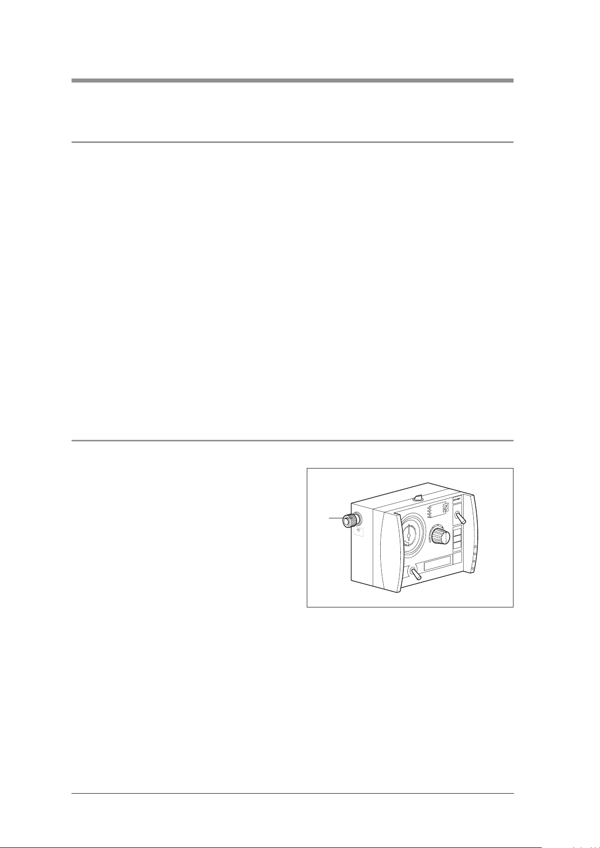
6.2 Replacing the sieve in the compressed gas connection
Tools required:
• Slotted screwdriver,
• Tweezers.
1. Unscrew the slotted screw at the compressed
gas connection 10.
2. Using the tweezers, remove the sieve set 62.
3. Carefully insert a new sieve set 62 into the
compressed gas connection.
4. Screw the slotted screw back into the compressed gas connection.
62
Repair information and repair instructions 21
Page 22

6.3 Changing the foam insert in the pressure relief valve outlet
Tools required:
• Tweezers.
1. Use tweezers to remove foam insert 15.
2. Place a new foam insert 15 in the outlet.
6.4 Opening the device
Tools required:
15
• Crosstip screwdriver, size 2.
1. Carefully place the device on a non-slip surface and unscrew the 6 screw 40 the rear panel of the device.
2. Pull off the housing base section 28 and fold it
away.
3. Next, loosen the connecting tube 46 from the
oxygen inlet by pushed back the sleeve on the
angular bush 29 and pulling out the tube.
40
up to appliance no.:
Basic 1019; Basic p 1399
29
46
28
from appliance no.:
Basic 1020; Basic p 1400
40
22 Repair information and repair instructions
Page 23

6.5 Closing the device
Tools required:
• Crosstip screwdriver, size 2.
1. Push the connecting hose 46 into the angular
bush 29 as far as it will go.
2. Place the housing base section 28 onto the upper housing section.
Take care to ensure that none of the lines are
pinched and that the twistlock 11, the
grommets 39 and the angled outlet or the pressure measurement connection 13 are correctly
seated.
3. Next, secure the housing base section using
the 6 screws 40.
4. Perform a functional check (see “3. Final
Check” on page 8).
28
29
46
11 11
angled outlet
13
39 39
up to appliance no.:
Basic 1019; Basic p 1399
6.6 Changing the batteries
Tools required:
• Crosstip screwdriver, size 2.
1. Open the device (see “6.4 Opening the device” on page 22).
2. The main battery 19 can be removed by lifting
the battery out of its holder and then pulling
connector X1 from the circuit board.
3. To remove the button cell 17, gently lift up the
plus contact and pull the button cell out sideways with your other hand.
4. Insert the new batteries by proceeding in the
reverse order.
Make sure that the wires for the main battery are
not pinched and that the button cell is inserted
with correct polarity!
5. Close the device (see “6.5 Closing the
device” on page 23).
6. Perform a functional check (see “3. Final
Check” on page 8).
40
28
from appliance no.:
Basic 1020; Basic p 1400
40
17
X1
19
Remember that used batteries must not be disposed of with your domestic waste. Used batteries should be
taken to a collection point in your area, or to a specialist dealer.
Repair information and repair instructions 23
Page 24

6.7 Replacing the fuse
Tools required:
• Crosstip screwdriver, size 2.
1. Open the device (see “6.4 Opening the device” on page 22).
2. Pull out the defective fuse 18 upwards.
3. Carefully press a new fuse 18 into the holder.
4. Close the device (see “6.5 Closing the
device” on page 23).
5. Perform a functional check (see “3. Final
Check” on page 8).
6.8 Replacing ventilation control knob
Tools required:
18
• Crosstip screwdriver, size 2,
• L-handled socket wrench 10 mm,
• Special tool WM 22829 from special tool set WM 15349,
• Calibration device WM 22836.
1. Remove the faulty ventilation control knob 5.
To do so, proceed as follows:
– Turn the control knob 35 as far as it will go
to the left, so that you have a reference
point when reassembling later.
– Prise off the cover 34.
– Hold the control knob with the special tool
and undo the nut with a tubular socket span-
ner (10 mm).
– Pull the control knob 35 off.
2. Attach the new control knob 35:
– Push the control knob 35 onto the spindle
almost as far as it will go.
– Turn the knob until the white line points to
the lowest MV value.
– Hold the knob with the special tool and
tighten the nut to secure it.
3. Check the control knob 35 readings: at the left
stop the white line must point to the lowest MV
value, at the right stop it must point to the highest value. If this is not the case, slacken the nut
and align the control knob correctly.
4. Place the cover 34 on the control knob 35.
5. Perform calibration (see “6.9 Calibration after
removal of PCB, ventilation control knob 5
and/or pneumatic block” on page 25).
5
35
34
(Two-way switch only on Basic p)
24 Repair information and repair instructions
Page 25

6.9 Calibration after removal of PCB, ventilation control knob 5 and/or pneumatic block
The ventilation control knob 5 controls an EPROM on the printed circuit board of the MEDUMAT Basic /
Basic p. To ensure correct setting of the minute ventilation, the EPROM must be calibrated after every removal
of the PCB, the control knob 5 or the pneumatic block.
Tools required:
• Crosstip screwdriver, size 2
• Calibration device WM 22836.
1. Remove the back of the housing. To do so:
– Place the device on a non-slip surface and
unscrew the 6 screws 40 from the back of the
device.
– Pull off the lower part of the housing 28 and
swing it out of the way.
up to appliance no.:
Basic 1019; Basic p 1399
2. Now detach the connecting tube 46 from the
oxygen inlet by pushing back the angular
bush 29 and pulling out the tube.
3. Switch the calibration device off at the toggle
switch. The Status LED is not on.
4. Connect the power cord of the calibration
device to connector X6 on the circuit board of
the MEDUMAT Basic / Basic p.
5. Switch on the MEDUMAT Basic / Basic p.
You must hear the valve switch.
6. Switch on the calibration device at the toggle
switch. The Status LED lights up.
7. Press the bottom button Start/Stop on the cal-
ibration device. When it is pressed, all the
LEDs on the calibration device light up.
29
46
40
X6
S
28
40
from appliance no.:
Basic 1020; Basic p 1400
46
p
/
t
ic
a
s
a
m
B
u
6
1
d
a
/
e
5
d
r
M
a
d
n
a
t
0
1
4
1
/
7
1
0
3
Repair information and repair instructions 25
Page 26

8. As soon as you release the Start/Stop button,
communication between the devices is automatically established. While this is happening,
the LEDs 5/16, 17/14 and Start/Stop flash.
Once the Start/Stop LED stay on continuously
and LEDs 5/16 and 17/14 have gone out,
communication is established. The solenoid
valve of the MEDUMAT Basic / Basic p does
not switch any more.
9. Turn the ventilation control knob 5 on
MEDUMAT to the setting MV=5,
frequency=16.
10. Press the middle button on the calibration
device. The corresponding LED 5/16 must
light up.
11. Turn the ventilation control knob 5 on
MEDUMAT to the setting MV=17,
frequency=14.
12. Press the middle button on the calibration
device. The corresponding LED 17/14 must
light up.
13. Press the bottom button Start/Stop on the calibration device. All LEDs except Status go out.
You must hear the solenoid valve of the
MEDUMAT Basic / Basic p switching.
14. Switch off the calibration device at the toggle
switch.
15. Disconnect the calibration device from the
MEDUMAT.
16. Close the device (see “6.5 Closing the
device” on page 23).
17. Perform a functional check (see “3. Final
Check” on page 8).
18. Turn MEDUMAT Basic / Basic p off.
26 Repair information and repair instructions
Page 27

6.10 Replacing the alarm signalling device
Tools required:
• Crosstip screwdriver, size 2,
• Crosstip screwdriver, size 1.
1. Open the device (see “6.4 Opening the
device” on page 22).
2. Up to appliance no.: Basic 1019; Basic p 1399
Pull the pressure measurement connection 13
upwards out of the housing wall.
3. Pull the connector X5 from the circuit board.
42
4. Unscrew both screws 42.
5. Remove the defective alarm signalling
23
device 23.
6. Insert the new alarm signalling device 23.
7. Secure the alarm signalling device using the
two screws 42.
up to appliance no.:
Basic 1019; Basic p 1399
8. Push the connector X5 onto the contacts on the
circuit board.
9. Up to appliance no.: Basic 1019; Basic p 1399
Push the pressure measurement connection 13
42
into the wall of the housing.
10. Close the device (see “6.5 Closing the
device” on page 23).
23
11. Perform a functional check (see “3. Final
Check” on page 8).
from appliance no.:
Basic 1020; Basic p 1400
13
X5
X5
Repair information and repair instructions 27
Page 28

6.11 Replacing two-way switch for maximum ventilation pressure (MEDUMAT Basic / Basic p Basic p only)
Tools required:
• Crosstip screwdriver, size 2,
• Special socket spanner SW8 WM 22826.
1. Open the device (see “6.4 Opening the
device” on page 22).
2. The main battery 19 can be removed by lifting
the battery out of its holder and then pulling
connector X1 from the circuit board.
Pull on the connector only, not on the lead!
3. Turn the MEDUMAT Basic / Basic p round.
4. Unscrew the cap 27 from the two-way switch 9.
5. Unscrew the nut with the special socket spanner.
X1
19
6. Detach connector X3 from the PCB.
7. Remove the toggle switch 26.
8. Insert a new toggle switch 26 so that the red
wire points to the wall of the housing. This is the
only way to guarantee that the switch toggles
correctly.
9. Turn the MEDUMAT around and secure the
toggle switch firmly by tightening the nut.
10. Push the connector X3 onto the PCB contacts.
11. Connect the battery connector X1 to the PCB
and place the battery 19 in its holder.
12. Close the device (see “6.5 Closing the
device” on page 23).
13. Turn the MEDUMAT Basic / Basic p round.
14. Screw the cap 27 onto the toggle switch.
15. Perform a functional check (see “3. Final
Check” on page 8).
27 9
X1
19X326
27
28 Repair information and repair instructions
Page 29

6.12 Replacing the circuit board
Tools required:
• Crosstip screwdriver, size 2,
• Side nippers,
• Cable tie,
• Calibration device WM 22836.
1. Open the device (see “6.4 Opening the
device” on page 22).
2. Remove the battery 19 by lifting it out of its
holder and then pulling connector X1 from the
circuit board.
Only pull on the connector, not on the lead!
3. Pull connectors X2, X5, X4 (and also connector
X3 in Basic p) from the circuit board.
4. Release the flat cable from the locking
device X7: To do so, pull the upper part of the
locking device upwards. You can then pull out
the cable.
5. Carefully pull the tube 52 from the sensor B2.
6. Using side nippers, cut through the cable
tie 53 at the tube 47.
X7
X2
X5
X4
X1
19
X3
(Basic p only)
7. Carefully pull the tube 47 from the sensor B1.
If the tube cannot be pulled off, you may cut
through it (e.g. using a scalpel).
In such cases, the tube must be replaced (as
explained in step 9.
8. Unscrew the two screws 41 and remove the
defective circuit board 22.
9. If you have cut through the tube 47 under
point 7., please replace it as follows:
– Using side nippers, cut through the cable
tie 53 at the distributor.
– Pull off the tube.
– Slide a new tube 47 onto the distributor and
secure with a cable tie.
B252 47 B153
22
41
53
(Basic p only)
47
Repair information and repair instructions 29
Page 30

10. Replace the alarm signalling device (see
“6.10 Replacing the alarm signalling device”
on page 27).
11. Place the new circuit board 22 onto the spacer
brackets. The points of the spacer brackets
snap into the circuit board.
Make sure that no leads are beneath the circuit
board, where they may be pinched.
12. Secure the circuit board with the two short
screws 41.
13. Slide the tube 52 onto the sensor B2.
14. Slide the tube 47 onto the sensor B1 and secure it there with a cable tie.
15. Push the connectors X2, X5, X4 (and also connector X3 in the Basic p) onto the contacts of
the circuit board.
16. Connect the connector X1 of the battery to the
circuit board and insert the battery 19 into the
holder. Avoid pinching the battery cables.
17. Place the flat cable into the locking device X7:
To do so, pull the upper part of the locking
mechanism upwards, slide the cable into it,
and press the upper part down again.
18. Perform calibration (see “6.9 Calibration after
removal of PCB, ventilation control knob 5
and/or pneumatic block” on page 25).
19. Close the device (see “6.5 Closing the
device” on page 23).
20. Perform a functional check (see “3. Final
Check” on page 8).
X7
X2
X5
X4
52 47
X1
19
X3
(Basic p only)
30 Repair information and repair instructions
Page 31

6.13 Replacing the pressure gauge
Note: The pressure gauge is identical to the respiratory pressure meter described in the instructions for use.
Tools required:
• Crosstip screwdriver, size 2,
• Open-ended spanner SW 7,
• If necessary, side nippers,
• If necessary, cable tie.
1. Open the device (see “6.4 Opening the
device” on page 22).
2. Unscrew the circuit board (see „6.12 Replacing
the circuit board“ on page 29, steps 2. to 9.).
The tubes 52 and 47 may be left on the circuit
board.
3. Release the pressure gauge tube 51 by
pushing back the sleeve of the swivel screw
connection 33 and pulling out the tube.
51
33
4. Using an open-ended spanner (SW 7),
unscrew the swivel screw connection 33 from
the pressure gauge 1.
5. Using your fingers, press the pressure gauge 1
out of its holder.
Tip:
You will find the pressure gauge easier to remove
if you dribble a small amount of spirit between
the pressure gauge and the holder.
6. Wet a new pressure gauge 1 with a small
amount of spirit and press it into the holder.
Take care to install the gauge in the right position,
so that it is easy to read.
7. Screw the swivel screw connection 33 onto the
pressure gauge.
8. Push the pressure gauge tube 51 into the angular bush as far as it will go.
9. Secure the circuit board (see „6.12 Replacing
the circuit board“ on page 29, steps 11. to
18.).
10. Close the device (see “6.5 Closing the
device” on page 23).
11. Perform a functional check (see “3. Final
Check” on page 8).
1
51
(only
Basic p)
47
52
Repair information and repair instructions 31
Page 32

6.14 Replacing the pneumatic block
Tools required:
• Crosstip screwdriver, size 2,
• L-handled socket wrench 10 mm,
• Special tool WM 22829 from special tool set WM 15349,
• If necessary, side nippers,
• If necessary, cable tie,
• Calibration device WM 22836.
1. Remove the ventilation control knob 5. To do
so, proceed as follows:
– Turn the control knob 35 as far as it will go
to the left, so that you have a reference
point when reassembling later.
– Lift off the lid 34.
– Using the special tool, hold the control knob
steady and loosen the nuts with an L-handled
socket wrench (10 mm).
– Pull off the control knob 35.
2. Open the device (see “6.4 Opening the
device” on page 22).
5
35
34
(Two-way switch only on Basic p)
3. Unscrew the circuit board (see „6.12 Replacing
the circuit board“ on page 29, steps 2. to 9.).
You can leave the pressure measurement tube 47
attached to the circuit board.
4. Release the pressure tube 48 by pushing back
the sleeve of the inlet and pulling out the tube.
5. Pull the ventilation tube 45 from the pneumatic
block 24.
6. Pull the suction connector 43 from the pneumatic block 24.
7. Carefully pull the defective pneumatic block
upwards out of the housing.
8. Pull off the two grommets 39.
9. Take a new pneumatic block 24 and push the
grommets written side first onto the connection 12
and the valve 14.
39
39
43
48
(Basic p
only)
Pressure
measurement tubes
45+54
12
14
32 Repair information and repair instructions
Page 33

10. Insert the new pneumatic block into the
housing.
Make sure,
– That you push the rocker and the spindle
through the corresponding holes in the housing
– That no tubes or leads are underneath the
pneumatic block where they may be
pinched
– That the grommets are positioned correctly
in the housing wall (the housing wall must
be in the groove)
– That the pneumatic block is resting on the
four rubber buffers.
11. Slide the suction connector 43 and the ventilation tube 45 with the spring 54 onto the corresponding connections on the pneumatic
block 24 as far as they will go.
12. Slide the pressure tube 48 into the inlet of the
pneumatic block as far as it will go.
48
(Basic p
only)
13. Secure the circuit board (see „6.12 Replacing
the circuit board“ on page 29, steps 11. to
17.).
14. Turn the MEDUMAT Basic / Basic p round.
15. Attach the control knob 35. To do so, proceed
as follows:
– Slide the control knob 35 onto the spindle
as far as it will go.
– Turn the knob until the white line points to
the lowest value.
– Hold the knob steady with the special tool
and screw it down.
16. Check the display on the control knob 35:
when the knob is turned to the left stop the
white line must point to the lowest MV value,
when it is turned to the right stop the line must
point to the highest value. If this is not the case,
loosen the nuts and align the control knob 35.
17. Perform calibration (see “6.9 Calibration after re-
moval of PCB, ventilation control knob 5 and/or
pneumatic block” on page 25).
18. Close the device (see “6.5 Closing the
device” on page 23).
19. Turn the MEDUMAT Basic / Basic p round.
43 45+54
35
(Two-way switch only in Basic p)
Repair information and repair instructions 33
Page 34

20. Place the lid 34 on the knob 35.
21. Perform a functional check (see “3. Final
Check” on page 8).
35
5
34
(Two-way switch only on Basic p)
6.15 Replacing the pneumatic block with angled outlet
The pneumatic block with angled outlet is fitted as standard to MEDUMAT Basic / Basic p Basic from appliance No. 1020 and to MEDUMAT Basic / Basic p Basic p from appliance No. 1400 onward. Old
appliances should be converted not later than the 6-year service.
Tools required:
• Crosstip screwdriver, size 2,
• L-handled socket wrench 10 mm,
• Special tool WM 22829 from special tool set WM 15349,
• If necessary, side nippers,
• If necessary, cable tie,
• Special pliers WM 22928,
• Calibration device WM 22836.
1. Remove the ventilation control knob 5. To do
so, proceed as follows:
– Turn the control knob 35 as far as it will go
to the left, so that you have a reference
point when reassembling later.
– Lift off the lid 34.
– Using the special tool, hold the control knob
steady and loosen the nuts with an L-han-
dled socket wrench (10 mm).
– Pull off the control knob 35.
2. Open the device (see “6.4 Opening the
device” on page 22).
3. Unscrew the circuit board (see „6.12 Replacing
the circuit board“ on page 29, steps 2. to 9.).
You can leave the pressure measurement tube 47
attached to the circuit board.
35
5
34
(Two-way switch only on Basic p)
34 Repair information and repair instructions
47
Page 35

4. Pull the ventilation tube 45 from the pneumatic
block 24.
5. Pull the suction connector 43 from the pneumatic block 24.
6. Release the pressure tube 48 by pushing back
the sleeve of the inlet and pulling out the tube.
7. For devices with an angled connector:
Detach pressure measurement tube 50 from the
tube connector on pneumatic block 24.
8. Carefully pull the defective/old pneumatic
block upwards out of the housing.
9. Pull off the grommet 39 from the pneumatic
block 24.
For conversion of appliances up to No. 1019
(Basic) or 1399 (Basic p): go to step 10..
For replacement in appliances from No. 1020
(Basic) or 1400 (Basic p) onward: go to step 13..
10. Remove connection 13 for the pressure measurement tube from the upper part of the housing.
24
50
39
13
43
48
(Basic p
only)
Pressure
measurement tubes
45+54
11. Pull tube 49 off the T-piece and replace it with
the new tube 50 (use WM 22967!).
12. Route the tube so that it is below the valve insert locator and the alarm unit 23 and run it
along the inside wall of the housing.
13. Take a new or replacement pneumatic
block 24 and push the grommet 39 written side
first onto the valve 14.
14. Insert the new pneumatic block into the
housing and push tube 50 onto the pneumatic
block.
49
up to appliance no.:
Basic 1019; Basic p 1399
50
23
39
24
14
Repair information and repair instructions 35
Page 36

15. Now take the swivelling angled connector
and push it onto the connector of the pneumatic block. To fit the swivelling angled connector
properly into the upper housing section, lift the
pneumatic block slightly and push it over the
outer wall of the housing.
Make sure,
– That you push the rocker and the spindle
through the corresponding holes in the
housing
– That no tubes or leads are underneath the
pneumatic block where they may be
pinched
– That the grommet is positioned correctly in
the housing wall (the housing wall must be
in the groove)
– That the pneumatic block is resting on the
four rubber buffers.
For conversion: go to step 16..
For replacement: go to step 18..
16. Where present: If you have a device that you
have converted to a swivelling angled connector, you must insert sealing plug WM 22809
with O-ring 5-1.2 WM 1145/90 into the upper part of the housing where the pressure sensor tube was previously fitted.
17. Remove the “Sensor” plate from the housing.
18. Slide the suction connector 43 and the ventilation tube 45 with the spring 54 onto the corresponding connections on the pneumatic
block 24 as far as they will go.
19. Slide the pressure tube 48 into the inlet of the
pneumatic block as far as it will go.
20. Secure the circuit board (see „6.12 Replacing
the circuit board“ on page 29, steps 11. to
17.).
43
48
(Basic p
only)
45+54
21. Slide the tube 52 onto the sensor B2.
22. Turn the MEDUMAT Basic / Basic p round.
36 Repair information and repair instructions
B252 47
Page 37

23. Attach the control knob 35. To do so, proceed
as follows:
– Slide the control knob 35 onto the spindle
as far as it will go.
– Turn the knob until the white line points to
the lowest value.
– Hold the knob steady with the special tool
and screw it down.
24. Check the display on the control knob 35:
when the knob is turned to the left stop the
white line must point to the lowest MV value,
when it is turned to the right stop the line must
point to the highest value. If this is not the case,
loosen the nuts and align the control knob 35.
25. Perform calibration (see “6.9 Calibration after re-
moval of PCB, ventilation control knob 5 and/or
pneumatic block” on page 25).
26. Close the device (see “6.5 Closing the
device” on page 23).
27. Turn the MEDUMAT Basic / Basic p round.
28. Place the lid 34 on the knob 35.
29. Perform a functional check (see “3. Final
Check” on page 8).
35
5
34
(Two-way switch only on Basic p)
6.16 Replace 3/2 solenoid valve
Tools required:
• Crosstip screwdriver, size 2,
• 10 mm socket wrench,
• Special tool WM 22829 from set WM 15349
• If necessary, side nippers
• If necessary, cable tie
• Special pliers WM 22928
• Calibration device WM 22836
• Crosstip screwdriver, size 0
1. Open the device (see “6.4 Opening the
device” on page 22).
2. Remove the pneumatic block (see “6.15 Replacing the pneumatic block with
angled outlet” on page 34).
Repair information and repair instructions 37
Page 38

3. Undo the two mounting screws and remove
3/2 solenoid valve 64.
4. Replace the seal. Ensure that the seal is positioned correctly.
5. Screw new 3/2 solenoid valve 64 tight.
6. Refit the pneumatic block (see “6.15 Replacing the pneumatic block with angled outlet” on
page 34).
7. Close the device (see “6.5 Closing the
device” on page 23).
8. Perform a functional check (see “3. Final
Check” on page 8).
6.17 Changing the Air Mix/No Air Mix switch
Tools required:
• Crosstip screwdriver, size 2,
• L-handled socket wrench 10 mm,
• Open-ended spanner SW 17,
• Special tool WM 22829 from special tool set WM 15349,
64
• If necessary, side nippers,
• If necessary, cable tie,
• Vice with protective jaws,
• Calibration device WM 22836.
1. Up to appliance no. 1019 (Basic) or 1399
(Basic p):
Remove the pneumatic block from the housing
(see „6.14 Replacing the pneumatic block“ on
page 32, steps 1. to 7.).
From appliance no. 1020 (Basic) or 1400
(Basic p):
Remove the pneumatic block from the housing
(see „6.15 Replacing the pneumatic block with
angled outlet“ on page 34, steps 1. to 8.).
2. Clamp the pneumatic block in a vice with protective jaws.
3. Unscrew the rocker using an open-ended
spanner (SW 17).
4. Screw in a new rocker 25 with the seal.
Take care to ensure the correct installation
position:
The rocker must drop automatically into its end
position. It must not become stuck in an intermediate position.
25
38 Repair information and repair instructions
Page 39

Note:
The rocker will tend to drop into the lower
position.
5. Up to appliance no. 1019 (Basic) or 1399
(Basic p):
Re-install the pneumatic block (see „6.14 Replacing the pneumatic block“ on page 32,
steps 10. to 20.).
From appliance no. 1020 (Basic) or 1400
(Basic p):
Re-install the pneumatic block (see „6.15 Replacing the pneumatic block with
angled outlet“ on page 34, steps 14. to 28.).
6. Perform a functional check (see “3. Final
Check” on page 8).
6.18 Replace upper part of housing/control panel
Tools required:
• Crosstip screwdriver, size 2,
• Crosstip screwdriver, size 1,
• L-handled socket wrench 10 mm,
• Special tool WM 22829 from special tool set WM 15349,
• Special socket spanner 8 mm WM 22826,
• Flat nose pliers,
• Side nippers,
• Cable tie,
• Calibration device WM 22836.
Remove upper part of housing
1. Remove the ventilation control knob 5. Please
proceed as follows:
– Twist the control knob 35 to the left limit so
that you have a reference point when you
come to re-assemble it.
– Lift off the lid 34.
– Using the special tool, hold the control knob
steady and loosen the nuts with an L-han-
dled socket wrench (10 mm).
– Pull off the control knob 35.
2. Basic p only:
– Unscrew the cap 27 from the two-way
switch 9.
– Unscrew the nut with the special socket
spanner.
35
5
34
(Two-way switch only on Basic p)
27 9
Repair information and repair instructions 39
Page 40

3. Open the device (see “6.4 Opening the
device” on page 22).
4. Remove the circuit board (see „6.12 Replacing the circuit board“ on page 29, steps 2. to
9.).
The pressure measuring tube 47 may be left on
the circuit board.
5. Basic p only: remove the toggle switch 26.
6. Pull the ventilation tube 45 with the spring 54
from the pneumatic block 24 and the filter holder.
7. Pull the suction connector 43 from the pneumatic block 24 and the filter holder.
8. Release the pressure tube 48 by pushing back
the sleeve of the inlet and pulling out the tube.
48
26
(Basic p
only)
47
9. Carefully pull the pneumatic block upwards
out of the housing.
10. For devices with an angled connector:
Detach pressure measurement tube 50 from the
tube connector on pneumatic block 24.
11. Release the pressure gauge tube 51 by
pushing back the sleeve of the swivel screw
connection 33 and pulling out the tube.
12. Using your fingers, press the pressure gauge 1
out of the pressure gauge holder.
Tip:
You will find the pressure gauge easier to remove
if you dribble a small amount of spirit between
the pressure gauge and the holder.
13. Press the pressure gauge holder out of the
housing.
14. Take locking latch 11 out of the housing wall.
15. For conversion up to appliance No. 1019 (Basic)
or 1399 (Basic p):
Pull the pressure measurement connection 13
upwards out of the housing wall.
16. Unscrew both the screws 42 and remove the
alarm signalling device 23.
Filter holder
up to appliance no.:
Basic 1019; Basic p 1399
24
50
Filter holder
from appliance no.:
Basic 1020; Basic p 1400
11
43 45+54
43 45+54
234213
48
26
(Basic p
only)
47
51
33
1
40 Repair information and repair instructions
Page 41

17. For conversion up to appliance No. 1019 (Basic)
or 1399 (Basic p):
The pressure measuring tube 49 is secured to
the housing with a cable tie. Cut through the
cable tie with side nippers and remove the
tube or pull the tube off upwards the housing
with the cable tie.
up to appliance no.:
Basic 1019; Basic p 1399
49
18. Remove the filter insert:
– Pull the filter cap 55 out of the housing wall.
– Using a screwdriver, press out the pin 61.
– Take the valve insert 57 out of the recepta-
cle in the housing e.g. by tilting it with a
small screwdriver then pulling it out with flat
nose pliers.
19. Finally, remove the four rubber buffers 38.
from appliance no.:
Basic 1020; Basic p 1400
61
55
57
50
21
If you are not replacing the control panel, continue
at “Fit upper part of housing“.
Replace control panel
1. Remove upper part of housing (see above).
2. Push a screwdriver against the metal panel
from the inside until control panel 65 comes
loose.
3. Remove adhesive residues completely from the
upper part of the housing.
38
65
Repair information and repair instructions 41
Page 42

4. Pass the ribbon cable of new control panel 65
through the slot in the upper part of the housing
and glue on control panel 65.
p
ic
Bas
Fit upper part of housing
1. If your MEDUMAT Basic / Basic p is not to be
updated (straight connection on pneumatic
block), you will first have to file away a semicircle for the pressure measurement
connection 13.
2. Push the pressure gauge mounting 21 into the
new upper housing section 20.
3. Wet the rubber buffers 38 with a little spirit and
insert them.
4. Install the filter insert:
– Insert O-ring 60 in the corresponding
groove in the valve insert.
– Check that the membrane 59 is lying flush
and smooth against the valve insert 57.
– Press the valve insert, membrane first, into
the filter holder.
After installing, make sure that the valve insert
is lying straight in the holder.
– Take the pin 61 in your hand. The pin has a
notched side and a smooth side. Press the
pin with the smooth side forwards into the
small hole on the top of the filter holder until
it is flush with the holder. The pin holds the
valve insert in position.
– Push the filter cap 55 into the housing wall.
5. Wet the pressure gauge 1 with a small amount
of spirit and press it into the holder.
Observe the installation position so that the display remains clearly legible.
6. Push the pressure gauge tube 51 into the swivel screw connection 33 as far as it will go.
7. Place the pressure gauge tube 51 and the
pressure measuring tube 49/50 into the housing as illustrated.
8. For conversion up to appliance No. 1019 (Basic)
or 1399 (Basic p):
Secure the pressure measuring tube 49 to the
middle spacer with a cable tie.
up to appliance no.:
Basic 1019; Basic p 1399
11
O/I
65
61
59
57
60
55
51
33
1
9. Push locking latch 11 into the housing wall.
Remember that the slanted surface needs to be
pointing towards the device base later.
42 Repair information and repair instructions
49 Middle spacer
Page 43

from appliance no.:
Basic 1020; Basic p 1400
11
50
51
33
1
10. Basic p only:
– Insert the toggle switch 26 so that the red
wire points to the wall of the housing. This is
the only way to ensure the switch toggles
correctly.
– Turn the MEDUMAT round and secure the
toggle switch by tightening the nut.
11. Insert the alarm signalling device 23 and secure it with the screws 42.
12. For conversion up to appliance No. 1019 (Basic)
or 1399 (Basic p):
Push the connection 13 into the housing wall.
13. Insert the new pneumatic block 24 into the
housing.
Make sure that
– the connector X2 (on the long cable) is be-
side the connection 12.
– you push the rocker and the spindle through
the corresponding holes in the housing.
– no tubes or leads are underneath the pneu-
matic block where they may be pinched.
– the grommet 39 is positioned correctly in the
housing wall (the housing wall must be in
the groove).
– the pneumatic block is resting on the four
rubber buffers.
from appliance no.:
Basic 1020; Basic p 1400
up to appliance no.:
Basic 1019; Basic p 1399
24
X2
12
39
26
(Basic p only)2342
26
(Basic p only)234213
Repair information and repair instructions 43
Page 44

14. Make the tube connections:
– Push the suction connector 43 onto the rear
nozzle of the filter holder and onto the connection on the pneumatic block 24.
– Using the ventilation tube 45 with the
spring 54, connect the front nozzle of the filter holder to the pneumatic block 24.
– Make sure that all the tube ends are pushed
on to the limits.
15. Slide the pressure tube 48 into the inlet of the
pneumatic block as far as it will go.
16. Slide pressure measurement tube 50 onto the
tube connection of the angled outlet.
17. Secure the circuit board (see „6.12 Replacing
the circuit board“ on page 29, steps 11. to
17.).
18. Turn the MEDUMAT Basic / Basic p round.
19. Secure the ventilation control knob 5. Please
proceed as follows:
– Push the control knob 35 onto the spindle
just short of the limit.
– Twist the knob until the white line is pointing
to the lowest value.
– Hold the knob steady with the special tool
and screw it down.
20. Check the display on the control knob 35:
when turned to the left stop, the white line must
point to the lowest MV value.
If this is not the case, loosen the nuts and align
the control knob 35.
21. Perform calibration (see “6.9 Calibration after re-
moval of PCB, ventilation control knob 5 and/or
pneumatic block” on page 25).
22. Close the device (see “6.5 Closing the
device” on page 23).
23. Place the lid 34 on the knob 5.
24. Basic p only:
Carefully screw the cover 27 onto the two-way
switch 9.
25. Perform a functional check (see “3. Final
Check” on page 8).
48
50
43 45+54Filter holder
35
(Two-way switch only in Basic p)
35
5
34
52
44 Repair information and repair instructions
(Two-way switch only on Basic p)
Page 45

6.19 Replacing the housing base section
Tools required:
• Crosstip screwdriver, size 2,
• Open-ended spanner SW 13,
• Open-ended spanner SW 22,
• Special locknut tool G 3/8 WM 22827 and special spanner SW 17 WM 22828 from the special
tool set WM 15349,
• Vice with protective jaws.
1. Open the device (see “6.4 Opening the
device” on page 22).
2. Screw the special locknut tool onto the compressed gas connection 10.
3. Clamp the special locknut tool in a vice.
4. Tighten the nuts of the special locknut tool
against the pressure connection using an
open-ended spanner (SW 22).
5. Unscrew the angular bush 29 using an openended spanner (SW 13).
6. Using the special spanner (SW 17), loosen the
nut 30 and unscrew it.
7. Pull out the plate 31 upwards.
8. Remove the housing base section 28.
9. Remove rubber buffer 37 from the old device.
10. Place a new housing base section 28 on the
compressed gas connection 10.
11. Slide the plate 31 on the inside of the housing
onto the connection.
12. Tighten the nut 30 on the inside of the
connection.
13. Secure the angular bush 29 the connection.
14. Loosen the nuts of the special locknut tool using
the open-ended spanner (SW 22).
15. Open the vice.
16. Unscrew the special locknut tool from the compressed gas connection 10.
17. If your MEDUMAT Basic / Basic p is not to be
updated (straight connection on pneumatic
block), you will first have to file away a semicircle for the pressure measurement
connection 13.
18. Moisten the rubber buffers 37 of the defective
housing with a little spirit and insert them in the
new housing.
19. Close the device (see “6.5 Closing the
device” on page 23).
20. Perform a functional check (see “3. Final
Check” on page 8).
10
from appliance no.:
Basic 1020; Basic p 1400
up to appliance no.:
Basic 1019; Basic p 1399
2928 3110
30
Semi-circle for
pressure measurement
connection 13
37
Repair information and repair instructions 45
Page 46

6.20 Upgrading ventilation tube
In order to reduce the ventilation resistance of the respiration tube, the ventilation tube 45 on devices up to
device number 1011 (Basic) or 1137 (Basic p) should be upgraded in the course of the two-yearly service.
In addition a spring 54 is installed to prevent kinks in the tube.
Tools required:
• Crosstip screwdriver size 2,
• Socket wrench 7 mm,
• Side nippers or sharp knife,
• Spring 54.
1. Open the device (see “6.4 Opening the
device” on page 22).
2. Pull the ventilation tube 45 off the elbow connection.
3. Unscrew the elbow connection.
4. Unscrew the chromium-plated tube sleeve from
the elbow connection.
5. Screw the chromium-plated tube sleeve together with a sealing washer into the connection
(where the elbow connection was previously
installed).
6. Shorten the ventilation tube 45 to exactly
65 mm.
7. Slide the spring 54 onto the ventilation tube 45.
8. Push the ventilation tube 45 onto the tube nipple.
9. Close the device (see “6.5 Closing the
device” on page 23).
10. Perform a final check (see “3. Final Check” on
page 8).
Elbow
connector
45
46 Repair information and repair instructions
Tube
sleeve
45+54
Page 47

7. Spare parts
7.1 List of spare parts
Note:
The item numbers in the following table match the numbers in the text of these service and repair instructions
and the operating instructions.
Item no. Designation Order No.
1 Pressure gauge WM 22539
10 Pressurised gas connection (threaded connection), pre-assembled WM 22685
11 Twistlock for wall bracket WM 22642
13
15 Dust protector (foam insert) for pressure relief valve WM 22585
17
19
18 Fuse insert F 0,5 L 250 V WM 22651
20
21 Pressure gauge mounting WM 22504
Pressure measuring connection, pre-assembled (up to appliance
no. 1019 {Basic} or 1399 {Basic p})
Battery set,
consisting of:
– Button cell CR 2430
– Battery 3,6 Volt
Upper housing section, complete
– Basic
– Basic p
WM 22527
WM 15186
WM 22652
WM 22529
WM 22654
WM 22656
22
23 Alarm signalling device WM 22553
24
25 Set of rockers (for two-way switch Air Mix/No Air Mix 4) WM 15193
26 Toggle switch (for two-way switch Max. Ventilation Pressure 9) WM 15188
27 Push-on cap for switch lever (toggle switch) WM 22644
28
29 Angular bush 4/6 WM 22552
30 Nut M 14 x 1.5 WM 22586
31 Torque plate WM 22509
32 Screw-in connection WM 22596
33 Swivel screw connection 2/4 WM 22588
34
Set printed circuit board, Basic
Set printed circuit board, Basic p
Pneumatic block with angled outlet, complete, new
Pneumatic block with angled outlet, complete, replacement
Housing base section, complete*
– Basic
– Basic p
Lid, blue (Basic up to appliance no. 1010)
Lid, blue (Basic p up to appliance no. 1039)
Lid, white (Basic from appliance no. 1011)
Lid, white (Basic p from appliance no. 1040)
WM 15450
WM 15451
WM 22680
WM 22849
WM 22856
WM 22854
WM 4896
WM 4896
WM 22941
WM 22941
Spare parts 47
Page 48

35 Short button WM 4891
Set of rubber parts,
consisting of:
36
37
38
39
– Grommet for potentiometer
– Rubber buffer for housing base section
– Rubber buffer for upper housing section
– Grommet for connections 12 (up to appliance no. 1019
WM 15190
{Basic} or 1399 {Basic p}) and 14
Set of screws,
WM 15191
consisting of:
40
41
42
– Fillister-head screw KB 30 x 20
– Fillister-head screw KB 30 x 8
– Fillister-head screw KB 18 x 7,5
43 Suction connector WM 22598
44
Set of tubes for MEDUMAT,
consisting of:
45
46
47
48
49
50
51
52
53
– Tube, silicon 4/7, 65 long
– Tube, PU 4/6, 95 long
– Tube, PU 4/6, 82 long
– Tube, PU 4/6, 30 long
– Tube, PU 2/4, 105 long
– Tube, PU 1,6/3.2, 220 long (for angled connector)
– Tube, PU 2/4, 155 long
– Tube, silicon 4/7, 85 long
– Cable tie
WM 15187
54 – Spring WM 22804
55 Cover cap, drilled, for dust filter WM 4954
56
Filter insert set,
consisting of:
57
58
59
60
61
– Valve insert, complete
– Dust filter
– Valve membrane
– O-ring 13 x 1.25
– Split taper pin 1,5 x 8
WM 15185
Sieve set,
62
consisting of:
– Sieve
WM 15284
– Seal 3,5 x 6 x 0,5
Service label:
63
– for servicing in 1 years time
– for servicing in 2 years' time
– for servicing in 3 years' time
– for servicing in 4 years' time
– for servicing in 5 years' time
– for servicing in 6 years' time
WM 0301
WM 75340
WM 0302
WM 75341
WM 75640
WM 75339
64 Magnetic valve WM 22625
65
Control panel keypad Basic
Control panel keypad Basic p
WM 22559
WM 22548
Instructions for use WM 16182
* When ordering, please specify the model, device number and year of manufacture.
** When ordering, please specify year of next maintenance
48 Spare parts
Page 49

7.2 Maintenance set
Sets for devices already serviced with Set WM 15292 (Basic)/WM 15244 (Basic p)
(pneumatic block replacement)
Years 2 4 6 8 10 12 14
Maintenance
set Basic
Maintenance
set Basic p
Sets for devices not yet serviced with Set WM 15292 (Basic)/WM 15244 (Basic p)
(pneumatic block replacement)
Years 2 4 6 8 10 12 14 16
Maintenance
set Basic
Maintenance
set Basic p
Maintenance set 2 years (for MEDUMAT Basic and Basic p)
WM 15242 WM 15242 WM 15292 WM 15242 WM 15242 WM 15293 WM 15364
WM 15242 WM 15242 WM 15244 WM 15242 WM 15242 WM 15289 WM 15474
WM 15242 WM 15242 WM 15242 WM 15292 WM 15242 WM 15293 WM 15242 WM 15364
WM 15242 WM 15242 WM 15242 WM 15244 WM 15242 WM 15289 WM 15242 WM 15474
Set, WM 15242
consisting of:
• Battery
• Button cell
• Dust filter
• Foam insert for pressure relief valve
• Lip membranes
• Membrane for spontaneous breathing arm
Maintenance set 8 years (for MEDUMAT Basic)
Set, WM 15292
consisting of:
• Set WM 15242
• Rubber buffer pad
• Rubber buffer receptacle
• Set of tubes
• Pneumatic block, replacement
• Seal 3.5 x 6 x 0.5
• Sieve
• Membrane for expiration arm
• O-ring 15 x 1.5
• Valve membrane
• Suction connector
• O-ring 13 x 1.25
• Sealing plug
• O–ring 5 x 1.2
Maintenance set 8 years (for MEDUMAT Basic p)
Set, WM 15244
consisting of:
• Set WM 15242
• Rubber buffer pad
• Set of tubes
• Toggle switch
Spare parts 49
Page 50

• Push-on cap for switch lever
• Rubber buffer receptacle
• Pneumatic block, replacement
• Suction connector
• O-ring 13 x 1.25
• Sealing plug
Maintenance set 12 years (for MEDUMAT Basic)
Set, WM 15293
consisting of:
• Set WM 15242
• Printed circuit board /PCB
MEDUMAT
• Alarm signalling device
• Cable tie
Maintenance set 12 years (for MEDUMAT Basic p)
Set, WM 15289
consisting of:
• Set WM 15242
• Toggle switch
• Push-on cap for switch lever
• Printed circuit board /PCB
MEDUMAT
• Alarm signalling device
• Cable tie
Maintenance set (14) 16 years (for MEDUMAT Basic)
Set, WM 15364
consisting of:
• Set WM 15242
• Rubber buffer pad
• Suction connector
• O-ring 13 x 1.25
• Rubber buffer receptacle
• Set of tubes
• Pneumatic block, new
• Sealing plug
• O–ring 5 x 1.2
Maintenance set (14) 16 years (for MEDUMAT Basic p)
Set, WM 15474
consisting of:
• Set WM 15242
• Rubber buffer pad
• Set of tubes
• Toggle switch
• Push-on cap for switch lever
• Rubber buffer receptacle
• Pneumatic block, new
• Suction connector
• O-ring 13 x 1.25
• Sealing plug
50 Spare parts
Page 51

8. Tools and test equipment
Below is a list of all tools and test equipment used in these service and repair instructions.
The particular tools and test equipment required are outlined in the respective chapter.
Special tools can be purchased from the manufacturer Weinmann.
8.1 General tools
• Slotted screwdriver size 0.5 x 3 x 100;
• Crosstip screwdriver, size 1;
• Crosstip screwdriver, size 2;
• Open-ended spanner SW 7
for tube connection of pressure gauge;
• Socket wrench 7 mm
• Open-ended spanner SW 13,
for elbow connector at O2 inlet;
• Open-ended spanner SW 17
for rocker valves;
• Open-ended spanner SW 22
for special locknut tool;
• L-handled socket wrench 10 mm
for control knob;
• Tweezers
for sieve set;
• Side nippers;
• Flat nose pliers.
8.2 Special tools
The following tools are available from the manufacturers Weinmann:
• Special tool set, consisting of: WM 15349
– Special locknut tool G 3/8 WM 22827
for unlocking the threaded connection
on the O2 inlet
– Special spanner SW 17 WM 22828
for lock nut on O2 inlet
– Special tool WM 22829
for holding the control knob
– Set: hose with injector WM 15359
– Special pliers WM 22928
• Set, supply test Medumat / Modules WM 15440
• Set, test set respiration and pressure reducer flow WM 15443
• Special socket spanner SW8, WM 22862
for removing toggle switch for P
in MEDUMAT Basic / Basic p Basic p
• Calibration device WM 22836
max
Tools and test equipment 51
Page 52

8.3 Test equipment
• Oxygen concentration measuring device, Type Oxycontrol WM 13550
• Volumetric flowmeter
Type Flow Analyser PF-300
obtainable from:
SI-special instruments GmbH
Strelgasse 2
D-86720 Nördlingen
Tel.: +49 90 81 / 2 20 61 or 2 20 62
Fax: +49 90 81 / 2 20 63
www.specialinstruments.com
or
Type RT 200 (Timeter)
obtainable from:
Allied Healthcare Products Inc.
1720 Sublette Avenue
St. Louis, Missouri, MO 63110
USA
Tel.: 001-800-444-3954
Fax: 001-314-771-5183
or
Type EKU VIP-Ventilatortester
obtainable from:
EKU Elektronik GmbH
Feldstrasse 9a
56291 Leiningen
Tel.: 06746-1018
Fax: 06746-8484
www.eku-elektronik.de
• Test set for final check WM 15339
• Adjustable orifice, e.g. ball valve,
internal diameter ≥ 10 mm
• Pressure gauge 0 to 6.3 bar, class 1.6;
• Pressure gauge 0 – 100 mbar, class 1.6
Type WIKA
obtainable from:
Alexander Wiegand GmbH & Co.
Alexander-Wiegand-Strasse 30
63911 Klingenberg am Main
Tel. 09372/1320
52 Tools and test equipment
Page 53

9. Technical data
MEDUMAT Basic / Basic p
Product category
according to
II b
93/42/EEC
Device dimensions
D x W x H
Weight incl.
accessories
190 x 110 x 90
inc. connections
approx. 1.1 kg
Operating parameters
– temperature range
– humidity
– air pressure
-18 °C to +60 °C
15 % to 95 %
70 kPa to 110 kPa
Storage -40 °C to +70 °C
Electromagnetic
compatibility (EMC) in
accordance with
EN 60601-1-2 and
EN 794-3:
– interference
EN 55011
suppression
– interference immunity
Control
EN 61000-4-2 to 3
Timing pulse, constant
volume
Gas input Medicinal oxygen
Operating pressure 2.7 to 6.0 bar
Minimal gas volume
required
70 l/min O
2
Insp.-exp. ratio 1:1.67
Ventilation frequency
Minute volume (MV)
infinitely variable
from 10 to 30 min
-1
infinitely variable 3 to
20 l/min
MV tolerances:
– room temp. (20 °C)
for 3 l/min = ±20%
for >3 l/min = ±15%
– -18 °C to +60 °C
for 3 l/min = ±35%
for >3 l/min = ±20%
max. ventilation
pressure
– MEDUMAT Basic /
Basic p Basic
– MEDUMAT Basic /
45 mbar
20 mbar or 45 mbar
Basic p Basic p
O2 concentration
– Air Mix
– No Air Mix
see page 55
100% O
2
MEDUMAT Basic / Basic p
High-pressure gas
connection
Connection to
ventilation hose
Patient valve
– inspiration tube
Patient valve
– expiration tube
Power supply
External thread G 3/8
External diameter
13 mm
15 mm socket
22 mm plug
ISO 5356-1
30 mm socket
ISO 5356-1
maintenance-free lithium
battery 3.6 V; 5.2 Ah
life expectation
max. storage:
Auxiliary energy for
> 2 years
10 years after delivery
Button cell CR2430
alarm system
max. storage:
10 years after delivery
F1 fuse T 500 L 250V
Ventilation hose Spiral silicone NW 10
Degree of protection
against water
Standard complied
with
IPX 4
EN 794–3;
EN 60601–1;
prEN 1789
Alarm sound pressure 54 dB A
Manometer accuracy Class 1.6
Patient valve resistance
(complied with
EN 794-3):
– Inspiration
– expiration
– spontaneous
<6 mbar at 60 l/min
<6 mbar at 60 l/min
<1.5 mbar at 30 l/min
breathing
Elasticity of breathing
system
Patient valve dead
space
Negligible
12.8 ml
Components
dependent on the
Patient valve
direction of flow
Parts containing latex None
Subject to technical change
without notice.
Technical data 53
Page 54

9.1 Pneumatics
input pressure
2.7 - 6 bar
frequency regulator
P/E converter
A/D converter
evaluation electronics
p
V1
pressure regulator
patient
valve
exp.-insp.
P/E converter
valve rocker
V2
manometer
injector unit
V8
relief valve
V6
V3
amplifier valve
V4
exhaust valve
V9
non-return valve
V7
air inlet
V5
regulator valve
air mix valve
The input pressure at p is max. 6 bar. This is reduced by V1 to 2.7 bar dyn. This is the input pressure at V6,
V2 and V3.
Inspiration/No Air Mix
Valve rocker V6 is opened and switches over V7. An electrical impulse to V2 opens V3 and closes V4. Oxygen flows through V5 into injector unit V9 and onwards to the patient valve. If the ventilation pressure in the
patient valve rises above 100 mbar, the relief valve V8 will open.
Inspiration/Air Mix
Valve rocker V6 is closed. This closes V7. O2 flows into injector unit V9 through V5 and sucks in air through
V7. The air-oxygen mixture flows to the patient valve.
Expiration/Air Mix or No Air Mix
Another electrical impulse closes V2. Exhaust valve V4 opens and exhausts injector unit V9. The patient breathes
out through the patient valve.
Patient valve
The respiratory gas flows into the patient’s airways during inspiration. The expiratory pressure then switches the valve over
and enables the patient to breathe out.
Inspiration
Patient
Inspiration
Expiration
Expiration
54 Technical data
Medumat
Page 55

9.2 O2 content when using Air Mix
The following diagram shows the oxygen concentration prevailing at various counter-pressures and minute
volumes when Air Mix is switched on.
100
95
90
85
80
(%)
2
75
O
70
65
60
55
50
3 5 7 9 11 14 17 20
10 mbar counter-pressure
15 mbar counter-pressure
30 mbar counter-pressure
Minute volume (l/min)
In isolated cases the minute volume (MV) deviations may be higher at ventilation pressures in excess of
30 mbar.
Technical data 55
Page 56

10. Technical Changes
Technical change From Device No. Date
Lid, white
1011
Basic
1040
Basic p
20.07.00
28.01.99
Ventilation tube 45 rerouted and fitted with spring 54.
(see “6.20 Upgrading ventilation tube” on page 46)
Pressure controller spindle secured against vibration
Angled outlet
Software modification for cardiac massage and stenosis
alarm
Housing parts, reinforced
Potientiometer cable, extended
1011
Basic
1137
Basic p
1011
Basic
1137
Basic p
1020
Basic
1400
Basic p
1014
Basic
1400
Basic p
1014
Basic
1458
Basic p
1014
Basic
1470
Basic p
20.07.00
6.07.00
20.07.00
6.07.00
21.07.03
21.07.03
03.12.03
10.12.03
12.03.04
12.03.04
17.05.04
17.05.04
56 Technical Changes
Page 57

11. Repair and inspection log
Inspection log – safety check in accordance with EEC - Directive WM 22671
Device: MEDUMAT Basic Device-No.: .......………..... WM-Nr.: 22600 Date of manufacture: ……...................
MEDUMAT Basic p Device-No.: .......………..... WM-Nr.: 22650 Date of manufacture: ……...................
1. Test equipment
• Test pressure 6 ± 0.15 bar, pressure gauge 0 – 6.3 bar, class 1,6
• Volumetric flow measuring device RT 200; adjustable diaphragm 10 mbar; test set WM 15335
• Oxygen measuring device
2. Preparation for testing
• Connect MEDUMAT to the test unit.
• Set MEDUMAT to the “No Air Mix” setting at f = 30/min, MV = 3 l/min and p
3. Input the device data
• Enter the above device data Measurement OK not OK
4. Leak tests at 6 bar
• Pressure drop, inlet side with lever set to “No Air Mix” ≤ 0.2 bar/min
• Pressure drop, inlet side with lever set to “Air Mix” ≤ 0.2 bar/min
• Pressure drop in pressure measuring segment ≤ 2.0 mbar/min
• Pressure reading deviation less than ±1.5 mbar
5. Self-test after switching on the device
• All 4 LEDs are illuminated simultaneously and the alarm sounds
6. Functional check and alarms
• With lever set to “Air Mix”, Stenosis alarm is triggered
• With lever set to “No Air Mix”, Stenosis alarm is triggered
• Alarm acknowledgement function
• Disconnection alarm is triggered
• Pressure alarm is triggered
7. Frequency check – frequency setting
• Frequency 16 / min ± 2
• Frequency 10 / min ± 2
• Frequency 30 / min ± 2
8. Tidal volume check at 4.5 bar admission pressure and 10 mbar counterpressure
• f = 16 / min , MV = 20 l/min: AV = 1250 ± 190 ml
• f = 10 / min , MV = 11 l/min: AV = 1100 ± 170 ml
• f = 30 / min , MV = 3 l/min: AV = 100 ± 20 ml
9. Check O2 concentration at f = 10 / min and MV = 11 l/min
• O2 concentration with “No Air Mix” > 98 Vol.%
•O2 concentration with “Air Mix“” > 50 – 65 Vol.%
10.Functional check – pressure limit with No Air Mix
• Pressure limit responds at 20 ± 5 mbar (only MEDUMAT Basic p)
• Pressure limit responds at 45 ± 5 mbar (MEDUMAT Basic and Basic p)
11.Functional check – ventilation valve without patient valve
• Test bag is inflated completely, respirator is then vented audibly.
12.Check the equipment and accessories (system components)
• Respiration tube with patient valve undamaged and fully functional
• Test set for functional check fully functional
• Pressure-reducer fully functional
•O2 cylinder within the inspection limits; valve fully functional
• Support plate complete and fully functional
• Medcal products book
• Instructions for use
13.Check external condition
• Zero setting of manometer
• Connection thread and knobs fully functional
Servicing carried out: yes no Final inspection carried out:______ _______ __________________
date inspector no. signature
= 45 mbar.
max
1/min
1/min
1/min
Air Mix No Air Mix
ml
ml
ml
mbar
mbar
present yes no
Repair and inspection log 57
Page 58

Page 59

Page 60

Weinmann
Geräte für Medizin GmbH+Co. KG
P.O. Box 540268 • D-22502 Hamburg
Kronsaalsweg 40 • D-22525 Hamburg
T: +49-(0)40-5 47 02-0
F: +49-(0)40-5 47 02-461
E: info@weinmann.de
www.weinmann.de
Center for
Production, Logistics, Service
Weinmann
Geräte für Medizin GmbH+Co. KG
Siebenstücken 14
D-24558 Henstedt-Ulzburg
T: +49-(0)4193-88 91-0
F: +49-(0)4193-88 91-450
WM 16287e - 04.10
 Loading...