


¤
TM
Operator’s Manual
CT-238
AC/DC Current Probe
•Bedienungsanleitung
•Manuel d’Utilisation
Accessory

WARRANTY
The CT238 Current Clamp is warranted against any defects of material or workmanship within a period of one (1) year following the date of purchase of the multimeter by the original purchaser or original user.
Any multimeter claimed to be defective during the warranty period should be returned with proof of purchase to an authorized Wavetek Meterman Service Center or to the local Wavetek Meterman dealer or distributor where your multimeter was purchased. See maintenance section for details.
Any implied warranties arising out of the sale of a Wavetek Meterman multimeter, including but not limited to implied warranties of merchantability and fitness for a particular purpose, are limited in duration to the above stated one (1) year period. Wavetek Meterman shall not be liable for loss of use of the multimeter or other incidental or consequential damages, expenses, or economical loss or for any claim or claims for such damage, expenses or economical loss.
Some states do not allow limitations on how long implied warranties last or the exclusion or limitation of incidental or consequential damages, so the above limitations or exclusions may not apply to you.
This warranty gives you specific legal rights, and you may also have other rights which vary from state to state.
WARNINGS AND PRECAUTION
PLEASE READ SECTION 2 – SPECIFICATION BEFORE OPERATING THE INSTRUMENT
Exceeding the maximum limits of this instrument is DANGEROUS.
Exceeding these limits will expose you to physical injury or even death and will almost certainly damage your instrument. Even low-level voltages and currents are capable of causing serious injury or even death.
Please do not use this or any piece ot test equipment without proper training. Individual functions and ranges have different overload limits. It is VERY IMPORTANT that you make yourself aware of these overload limits. Check the specifications of these overload limits.
OPERATING INSTRUCTIONS
International Electrical Symbols
 Caution! Refer to this manual before using the probe.
Probe is protected by Reinforced or Double Insulation.
CONTENTS
|
Warranty Statement |
Page 1 |
1 |
INTRODUCTION |
Page 2 |
2 |
SPECIFICATIONS |
|
2.1 |
Electrical Data |
Page 3 |
2.2 |
General Data |
Page 3 |
3 |
OPERATING INSTRUCTIONS |
|
3.1 |
Switch On |
Page 3 |
3.2 |
Zero Adjustment |
Page 3 |
3.3 |
Current Measurement |
Page 3 |
4 |
SAFETY |
Page 4 |
5 |
BATTERY REPLACEMENT |
Page 4 |
6 |
FACTORY SERVICE |
Page 4 |
7 |
FREQUENCY RESPONSE |
|
|
AND ACCURACY CURVES |
Page 6 |
– 1 –

current flow is in the direction shown by the arrow on the probe.
True r.m.s. readings may be obtained by using an appropriate true r.m.s. reading
multimeter.
4. SAFETY
This instrument is designed to be safe under the following conditions:
-indoor use
-altitude up to 2000m
-temperature 0°C to +50°C
-maximum relative humidity 80% for temperatures up to 31°C decreasing linearly to 40% relative humidity at 50°C.
Use of the probe on uninsulated conductors is limited to 300V r.m.s or d.c. and frequencies below 1kHz.
Safety in its use is the responsibility of the operator who must be a suitably qualified or authorised person.
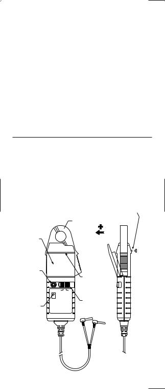
Do not use the probe if any part of the probe including the lead and connector(s) appear to be damaged or if a malfunction of the instrument is suspected. When using the probe ensure that your fingers are behind the protective barrier see Fig. 1.
Clean the case periodically by wiping it with a damp cloth and detergent. Do not use abrasive cleaners or solvents. Do not immerse the probe in liquids.
5. BATTERY REPLACEMENT
SAFETY WARNING: Before removing the battery cover, make sure that the probe is remote from any live electrical circuit.
The red LED will flash when the minimum operating voltage is approached. Refer to Fig.1 and use the following procedure.
Unclamp the probe from the conductor, turn it off using the On - Off switch and disconnect the output leads from external equipment. Loosen the captive screw which secures the battery cover. Lift the cover through 30° and pull it clear of the probe body as shown in Fig 1. The battery is then accessible. Replace the battery and re-fit the battery cover and fasten the screw.Replacement with other than the specified type of battery will invalidate the warranty. Fit only Type 9 V PP3, Alkaline (MN 1604 ).
BATTERY COVER SCREW (CAPTIVE)
SCHRAUBE, BATTERIEFACH
VIS, COMPARTIMENT PILE
JAWS
ZANGE
BATTERY COVER  PINCE
PINCE
BATTERIEFACHDECKEL
COUVERCLE, COMP.
PILE
ZERO ADJUST |
|
|
NULLABGLEICH |
PROTECTIVE BARRIER |
|
AJUSTAGE DU |
||
SCHUTZSPERRE |
||
ZERO |
||
BOUCLIER DE |
||
|
||
ZERO |
PROTECTION |
|
|
||
ADJUST |
|
|
OFF |
ON |
ON CT238 |
ON/OFF SWITCH |
AC/DC CURRENT PROBE |
|
MAX CURRENT: 20A RMS |
EIN/AUS SCHALTER |
OUTPUT: 100mV/A |
|
LED |
BOUTON MARCHE/ |
|
ARRET |
Fig. 1
– 3 –

6. SERVICE INFORMATION
Read the warranty located at the front of this manual before requesting warranty or non-warranty repairs. For warranty repairs, any multimeter claimed to be defective can be returned to any Wavetek Meterman authorized distributor or to a Wavetek Meterman Service Center for an over-the-counter exchange for the same or like product. Non-warranty repairs should be sent to a Wavetek Meterman Service Center. Please call Wavetek Meterman or enquire at your point of purchase for the nearest location and current repair rates. All multimeters returned for warranty or non-warranty repair or for calibration should be accompanied by the following information or items: company name, customer’s name, address, telephone number, proof of purchase (warranty repairs), a brief description of the problem or the service requested, and the appropriate service charge (for non-warranty repairs). Please include the test leads with the meter. Service charges should be remitted in the form of a check, a money order, credit card with expiration date, or a purchase order made payable to Wavetek Meterman or to the specific service center. For minimum turn-around time on out-of-warranty repairs please phone in advance for service charge rates. The clamp should be shipped with transportation charges prepaid to one of the following addresses or to a service center:
in U.S.A. |
in Canada |
in Europe |
Wavetek Meterman |
Wavetek Meterman |
Wavetek Meterman |
1420 75th Street SW |
400 Britannia Rd. E.Unit #1 |
52 Hurricane Way |
Everett, WA 98203 |
Mississauga, ON L4Z 1X9 |
Norwich, NR6 6JB, U.K. |
Tel: 877-596-2680 |
Tel: (905) 890-7600 |
Tel: int + 44-1603-404824 |
Fax: 425-446-6390 |
Fax: (905) 890-6866 |
Fax: int + 44-1603- |
482409 |
|
|
The instrument will be returned with the transportation charges paid by Wavetek Meterman.
– 4 –

.7 Frequency Response
Phase shift in degrees • Phasenverschiebung in Grad
Frequency in Hz • Frequenz in Hz • Fréquence en Hz
Frequency in Hz; Frequenz in Hz; Fréquence en Hz
rés |
10 |
1000 |
20000 |
100000 |
deg |
0 |
|
|
|
en |
|
|
|
|
ge |
-2 |
|
|
|
éphasa |
-4 |
|
|
|
D |
|
|
|
|
Grad; |
-6 |
|
|
|
in |
|
|
|
|
ng |
-8 |
|
|
|
chiebu |
-10 |
Frequency Response CT-238 |
|
|
vers |
|
Frequenzgang CT-238 |
|
|
sen |
-12 |
Réponse de Fréquence CT-238 |
|
|
ah |
|
|
|
|
degrésP |
|
|
|
|
;se |
-14 |
ene |
|
geDr |
-20 |
•DéphasagePhase |
|
in |
-16 |
Sifht |
-18 |
deLectureLecture |
2,00 |
|
|
|
|
|
|
1,50 |
|
|
|
|
|
|
|
de |
|
|
|
|
|
|
|
|
|
|
|
|
|
|
|
Erreur |
1,00 |
|
|
|
|
|
|
•Erreur |
|
|
|
|
|
|
|
% |
|
|
|
|
|
|
|
Ablesefehler |
0,50 |
50mA |
|
|
|
|
|
|
|
|
|
|
|
||
0,00 |
5 |
10 |
15 |
20 |
25 |
30 |
|
|
|
|
|
|
|
||
|
|
|
|
|
|
|
|
Ablesefehler; |
|
|
|
|
|
|
A |
% |
-0,50 |
|
|
|
|
|
|
% |
|
|
|
|
|
|
|
• |
|
|
|
|
|
|
|
readingReading; |
-1,00 |
|
Typical Accuracy; CT-238 |
|
|
||
|
Typische Genauigkeit, CT-238 |
|
|
||||
|
|
|
|
||||
Of |
-1,50 |
|
Précision Typique, CT-238 |
|
|
||
of |
|
|
|
|
|
|
|
Error |
|
|
|
|
|
|
|
Error |
-2,00 |
|
|
|
|
|
|
% |
|
|
|
|
|
|
|
% |
|
|
|
|
|
|
|
Gain in dB • Verstärkung in dB • Gain en dB
Gain in dB; Verstärkung in dB; Gain en dB
FrequencyIninHz; •Frequenz in Hzz;• FréquenceenenHzHz
10 |
1000 |
20000 |
100000 |
1 |
|
|
|
0 |
|
|
|
-1 |
Frequency Response CT-238 |
|
|
|
|
|
|
|
Frequenzgang CT-238 |
|
|
|
Réponse de Fréquence CT-238 |
|
|
-2
-3 |
Fig. 2 |
– 5 –
 Loading...