


WARRANTY
The 320B, HD110, HD110T Digital Multimeters are warranted against any defects of material or workmanship within a period of one (1) year following the date of purchase of the multimeter by the original purchaser or original user.
Any multimeter claimed to be defective during the warranty period should be returned with proof of purchase to an authorized Wavetek Meterman Service Center or to the local Wavetek Meterman dealer or distributor where your multimeter was purchased. See maintenance section for details.
Any implied warranties arising out of the sale of a Wavetek Meterman multimeter, including but not limited to implied warranties of merchantability and fitness for a particular purpose, are limited in duration to the above stated one (1) year period. Wavetek Meterman shall not be liable for loss of use of the multimeter or other incidental or consequential damages, expenses, or economical loss or for any claim or claims for such damage, expenses or economical loss.
Some states do not allow limitations on how long implied warranties last or the exclusion or limitation of incidental or consequential damages, so the above limitations or exclusions may not apply to you.
This warranty gives you specific legal rights, and you may also have other rights which vary from state to state.
D • GEWÄHRLEISTUNG
Die Digitale Multimeter Modelle 320B, HD110, HD110T sind ab Kaufdatum für ein (1) Jahr gegen Materialund Herstellungsfehler gewährleistet. Siehe Kapitel "Unterhalt und Reparatur" für Einzelheiten.
Implizierte Schadeforderungen sind auch auf ein Jahr beschränkt. Wavetek Meterman ist nicht ansprechbar für Gebrauchsverluß oder Folgeschäden, Ausgaben, Gewinnverluß, usw.
E • GARANTIA
Los Multímetros Digitales Modelos 320B, HD110, HD110T están garantizados contra cualquier defecto de material o de mano de obra durante un periodo de un (1) año contado a partir de la fecha de adquisición. En la sección de "Mantenimiento y Reparación" se explican los detalles relativos a reparaciones en garantía.
Cualquier otra garantía implícita está también limitada al periodo citado de un (1) año. Wavetek Meterman no se hará responsable de pérdidas de uso del multí metro, ni de ningún otro daño accidental o consecuencial, gastos o pérdidas económicas, en ninguna reclamación a que pudiera haber lugar por dichos daños, gastos o pérdidas económicas.
F • GARANTIE
Les multimètres digitaux, Modèles 320B, HD110, HD110T sont garantis pour un (1) an à partir de la date d'achat contre les défauts de matériaux et de fabrication. Voir chapitre "Maintenance et Réparation" pour plus de détails.
Toute garantie impliquée est également limitée à un an. Wavetek Meterman ne peut être tenu responsable pour perte d'utilisation ou autres préjudices indirects, frais, perte de bénéfice, etc.
CONTENTS |
|
Safety Information.............................................................................................. |
2 |
Instrument Familiarization and Preparation for Use .......................................... |
4 |
Measurement Procedures ................................................................................ |
8 |
Specifications ................................................................................................ |
20 |
Troublehooting and Repair ............................................................................. |
28 |
D • Inhalt |
|
Sicherheitsinformationen ................................................................................. |
2 |
Vorstellung des Gerätes and Vorbereitung zur Anwendung .............................. |
4 |
Meßprozeduren ................................................................................................ |
8 |
Spezifikationen ............................................................................................... |
22 |
Unterhalt and Reparaturr ................................................................................ |
28 |
E • Contenidos |
|
Información de Seguridad ................................................................................ |
3 |
Familiarización con el instrumento y Preparación para su Uso ........................ |
4 |
Procedimientos de medida .............................................................................. |
8 |
Especificaciones ............................................................................................ |
24 |
Mantenimiento y Reparación ......................................................................... |
28 |
F • Contenu |
|
Informations de Sécurité .................................................................................. |
3 |
Présentation de l’Appareil et Preparations pour l'Emploi .................................. |
4 |
Procédures de Mesure ..................................................................................... |
8 |
Spécifications ................................................................................................ |
26 |
Dépannage et Réparation ............................................................................... |
28 |
– 1 –

WARNINGS AND PRECAUTIONS
NOTE: The symbol W on the front panel of the multimeter is an international symbol meaning "REFER TO OPERATING INTRUCTIONS. " Warnings and precautions to avoid personal injury and multimeter damage are listed in this section and in section "Operating Instructions ".
■ All inputs are protected against continuous overload conditions up to the limits 'of each function's stated input protection (see Specifications). It is very important that you make yourself familiar with these specifications. Never exceed these limits ! (1500VDC,1000VAC for DC and AC Volts and 60OVDC or AC for all other functions and ranges.) All voltage and resistance ranges are protected against voltage transients up to 6kV, 10µs duration. Current inputs are fuse-protected. ■Never attempt to measure voltages or currents that may exceed the ratings marked on the Function/Range Switch or terminal overlays, or the max. voltage rating above earth ground. ■Always use extreme caution when working near high voltage sources, especially when using the two highest VAC or VDC ranges. High voltages can be lethal and high voltage transients may occur at any time. ■Operator injury or damage to the multimeter may occur during current measurements if the fuse blows in a circuit which exhibits an open circuit voltage greater than 600 volts. ■Always inspect test leads, connectors, and probes for cracks or breaks in the insulation before each use. If any defects are found, replace item immediately. ■Never touch test leads, tips, or the circuit being tested while power is applied to the circuit being measured. Isolate yourself! ■When measuring current, check that the multimeter is connected in series with the load in which the current is to be measured. NEVER connect the multimeter ACROSS a voltage source. ■Please do not use this or any piece of test equipment without proper training. ■CRT SERVICE SAFETY REMINDER : A potential danger exists when measuring voltages in the horizontal output and damper stages of CRT equipment. (High voltage transients greater than 6,000 V). Please refer to your CRT service manual for proper servicing instructions.
D • Warnungen und Vorsichtsmaßnahmen
Anmerkung: Das Symbol W auf der Frontplatte des Multimeters bedeutet "GEBRAUCHSANLElTUNG LESEN".
■Überschreiten Sie nie die kontinuierlichen Überlastgrenzen (1500VDC, 1000VAC für Gleichund Wechselspannung und 600VDC or AC für alle andere Funktionen und Bereiche) oder andere Grenzen welche auf dem Gerät markiert sind. ■Außerste Vorsicht beim Messen von hohen Spannungen (<30V) wenn bei Strommessung die Sicherung in einem Schaltkreis mit Leerlaufspannung >600V durchbrennt beim
– 2 –

Messen an Bildröhrgeräten (hohe Spannungsspitzen) ■Unsersuchen Sie Gerät, Meßkabel, Verbinder, usw vor jeder Messung. Beschädigte Teile nicht verwenden o ■Meßspitzen and Stromkreis während der Messung nicht berühren Sich selbst isolieren! ■Bei Strommessung, Multimeter immer in Serie mit Schaltkreis verbinden -- Nie in parallel mit Schaltkreis.
E • Advertencias y Precauciones
NOTA: El símbolo W sobre el panel frontal del multímetro significa "CONSULTE EL MANUAL DE INSTRUCCIONES".
■No supere nunca los límites de sobrecarga continua (1500 VCC, 1000 VCA en VDC y VAC, y 600 VCC ■CA en las demás funciones y escalas), a otros límites marcados en el instrumento. ■Existe un serio peligro al medir altas tensiones (<30 V): ■cuando se mide corriente, si salta el fusible en un circuito con tensión de circuito abierto >600 V ■cuando se trabaja con TRCs (transitorios de alta tensión) ■Inspeccione las puntas de prueba, los conectores y las sondas antes de cada uso. Si encuentra cualquier defecto, no use el instrumento ■No toque nunca las puntas de prueba ni el circuito activo sobre el que está midiendo ■¡Aíslese Ud mismo! ■ AI medir corriente, conecte siempre el multímetro en serie con la carga - NUNCA en paralelo con una fuente de tensión.
F • Avertissements et Précautions
NOTE: Le symbole W sur la face avant de l'appareil veut dire "REFEREZVOUS AU MANUEL D'UTILISATION. "
■N'excédez jamais les limites de surcharge continue (1500Vcc, 1000Vca pour tension CC et CA et 600Vcc ou Vca pour autres fonctions et calibres) ou dáutres limites marquées sur l'appareil. ■Soyez très prudent quand vous mesurez des tensions élevées (<30V) pendant des mesures de courant quand le fusible saute dans un circuit avec tension en circuit ouvert de >600 volts En mesurant dans des appareils à tube cathodique (transitoires à haute tension) ■Inspectez appareil, câbles, connecteurs avant chaque mesure. N'utilisez pas des pièces endommagées ■Ne touchez pas les pointes de touche ou le circuit pendant les mesures Isolezvous ! ■Pour la mesure de courant, connectez l'appareil en série avec le circuit JAMAIS en parallèle avec une source de tension.
– 3 –
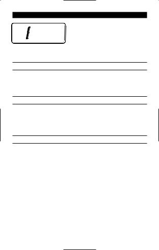
OVERLOAD INDICATION
Whenever an input signal is larger than the range selected, an overload symbol "1" will appear in the display. This indication is normal in the OHMS range when the leads are not connected to anything or when the measured
value is higher than the selected resistance range. In all other situations, take immediate steps to remove the cause of the overload condition.
D• Überlastanzeige
Wenn ein Signal die Bereichsgrenze überschreitet erscheint das Symbol "1" in der Anzeige. Diese Anzeige ist normal bei Widerstandsmessung wenn Mekabel/spitzen frei stehen oder wenn der Meßwert den Bereich überschreitet. In alien anderen Fällen ist die Ursache der Überlast sofort zu entfernen.
E • Indicación de sobrecarga
Siempre que una señal de entrada sea mayor que la escala seleccionada, aparece el símbolo "1" en el visualizador. Dicha indicación es la normal en la función OHMS cuando las puntas de prueba no están conectadas a ningún sitio, o cuando el valor medido es superior a la escala de resistencia seleccionada. En cualquier otra situación, cancele inmediatamente la causa de la sobrecarga.
F • Indication de Surcharge
Quand un signal dépasse la limite d'un calibre choisi, le sybole "1" apparait sur l'afficheur Ceci est normal dans les calibres de résistance, quand les pointes de touche ne sont pas connectées, ou si la résistance mesurée dépasse le calibre.
Dans tous les autres cas la cause du dépassement est à enlever immédiatement.
– 4 –
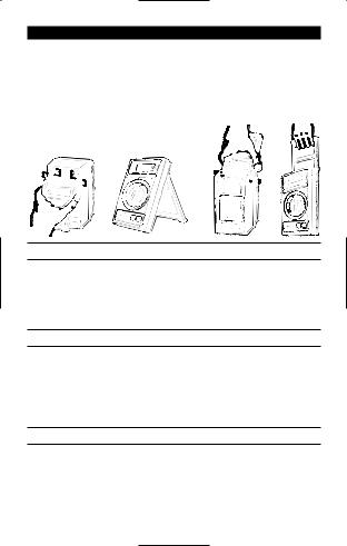
PREPARATION FOR USE - UNPACKING
Your shipping carton should include the multimeter, one TL-245 Probe Set (one black, one red), one 9V battery (installed), three fuses (two installed and one spare inside the case), plus one TP-255 thermocouple (HD110T only). If any of the items are damaged or missing, immediately return the complete package to the place of purchase for an exchange.
Tilt stand positions:
D • Gebrauchsvorbereitung - Auspacken
Die Verpackung sollte enthalten: ein Multimeter, ein Meßkabelsatz TL-245 (ein schwatz, ein rot), eine 9V Batterie (im Gerät), drei Sicherungen (zwei installiert; eine Reserve im Gerät), plus ein Thermoelement TP-255 (nur HD 110T). Wenn ein Teil fehlt oder beschädigt ist, gesamte Verpackung zur Verkaufstelle für einen Austausch zurückbringen, Kippständer wie oben angezeigt einstellen.
E • Preparación del multímetro para su uso - Desembalaje
El embalaje debe contener: el multímetro, un juego de puntas TL245 (una negra y una roja), una pila de 9 V (instalada), tres fusibles (dos instalados y uno de repuesto dentro de la carcasa), y (solamente en el HD T110T) un termopar TP-255. En caso de que falte algún componente o se observen daños, devuelva inmediatamente el paquete completo al lugar donde to adquirió para que se lo cambien. En la figura se muestran las posiciones inclinadas de apoyo.
E • Préparation pour l’Emploi - Déballage
Votre emballage doit contenir: un multimètre, un jeu de câbles de mesure TL245 (un rouge, un noir), une pile 9V (installée), trois fusibles (deux installés; un en réserve dans l'appareil), plus un thermocouple TP-255 (HD 110T uniquement). Si une pièce manque ou est endommagée, ramenez l'ensemble au point de vente pour un échange. Positionnez la béquille comme illustré ci-dessus.
– 5 –

– 6 –

INITIAL CHECKOUT
Connect red test lead to the V-W Input Connector and black test lead to the COM Input Connector. Turn the Function/Range Switch to the 20MW position. With the two test lead tips separated, the Digital Display should read 1 (overload). Turn Function/Range Switch to each W position. With test lead tips in contact, the display should read 0 in each position. (00.1 or 00.2 in 200W position due to test lead resistance). The decimal point should be positioned as follows:
|
20MW |
0.00 |
20kW |
0.00 |
|
|
2MW |
.000 |
2kW |
.000 |
|
|
200kW |
00.0 |
200W |
00.0 |
|
|
|
|
|
|
|
|
|
|
|
|
|
D • Funktionstest
Rotes Meßkabel mit V-W Eingang verbinden and schwarzes mit COM Eingang. Funktionsschalter auf 20MW stellen. Mit, freistehenden Prüfspitzen wird Überlast "1" angezeigt. Wählen Sie jede W Position an. Mit kurzgeschlossenen Meßspitzen wind in jeder Position Null angezeigt (00.1 oder 00.2 in 200W Position wegen Meßkabelwiderstand). Dezimalpunkt Position wie in obiger Tabelle.
E • Comprobación inicial
Conecte la punta de prueba roja al conector de entrada V-W, y la negra al conector de entrada COM. Gire el selector de Función/Escala/Off hasta la posición 20MW. Con los extremos de las pumas separados, el visualizador debe indicar "1" (sobrecarga). Vaya girando el selector por todas las posiciones de W. Con los extremos de las puntas de prueba en contacto, el visualizador debe indicar 0 en cada posición (00.1 0 00.2 en la posición 200W, debido a la resistencia de los cables). La posición del punto decimal debe ser como se muestra en la tabla anterior.
F • Test de Fonctionnement
Connectez le cordon rouge à l'entrée V-W et le noir à l'entrée COM. Placez le sélecteur de fonctions sur 20MW. Avec les pointes de touche séparées, l'afficheur montre "1" (dépassement de calibre). Choisissez chaque position W. Avec les pointes court-circuitées, l'affichage indique 0 dans chaque position (00.1 ou 00.2 en position 200W pour résistance des câbles). Positionnement du point décimal comme indiqué dans le tableau ci-dessus.
– 7 –

MEASURING PROCEDURES
General Procedures: When connecting or disconnecting test leads to a circuit, always first turn off power to device or circuit being tested and discharge all capacitors. If magnitude of signal is not known, set switch to highest range and reduce until satisfactory reading is obtained. Strictly observe the max input limits.
D • Meßprozeduren
Allgemein: Vor Verbinden und Trennen der Meßkabel mit dem Schaltkreis, diesen abschalten und Kondensatoren entladen, Bei unbekannter Signalgröße, bei höchstem Bereich beginnen and dann niedriger schalten bis gate Auflösung erreicht wird. Maximale Grenzen nicht überschreiten.
E • Procedimientos de medida
En general:. Cuando vaya a aplicar o retirar las pumas de prueba a/de un circuito, en primer lugar desconecte siempre la alimentación del dispositivo o circuito sometido a prueba y descargue todos los condensadores. si no conoce la magnitud de la señal, ponga el selector en la escala más alta y vaya reduciendo hasta obtener una lectura satisfactoria, Observe estrictamente los límites máximos de entrada .
F • Procédures de Mesure
Général: Avant de connecter ou de déconnecter les cordons de test, coupez I lálimentation du circuit mesuré et déchargez les condensateurs. Si la magnitude du signal n’est pas connue, commencez avec le calibre le plus élevé, et diminuez ensuite jusqu'à obtenir une bonne lecture. Ne dépassez pas les limites d'entrée.
DC AND VOLTAGE MEASUREMENT (See Fig 1)
Connect red test lead to V-W Input and black test lead to COM Input. Set Function/Range Switch to desired DCV or ACV position. Touch Probe tips across voltage source (in parallel with circuit). Voltage value will appear on Digital Display along with the voltage polarity (negative DC measurements).
Note for AC Measurements: The AC converter used in the HD110, HD110T and 320 models is "average-responding." An RMS value is determined by first rectifying and filtering the signal to obtain the average value. The average value is then scaled upward by a factor of 1.11 to obtain the RMS value. Different scaling factors need to be applied for other waveforms (1 for square waves; 1.733 for triangle; 3.247 for full wave rectified sine wave; 2.591 for half wave rectified sine wave). Please note that these correction factors only apply for standard waveforms that are free from noise and distortion. True RMS values of nonsinusoidal
– 8 –
– 9 –
 Loading...