


2020/30.Man.3x5,25/XPr 19/06/97 14:35 Page 1
O P E R AT O R ’ S M A N U A L
2020/2030
Autoranging Digital
Multimeters
B E D I E N U N G S A N L E I T U N G
M A N U A L D E I N S T R U C C I O N E S
MA N U E L D ’ U T I L I S AT I O N
2020/30.Man.3x5,25/XPr 19/06/97 14:35 Page 2
WARRANTY
The 2020 and 2030 Digital Multimeters are warranted against any defects of material or workmanship within a period of one (1) year following the date of purchase of the multimeter by the original purchaser or original user.
Any multimeter claimed to be defective during the warranty period should be returned with proof of purchase to an authorized Wavetek Corp. Service Center or to the local Wavetek dealer or distributor where your multimeter was purchased. See maintenance section for details.
Any implied warranties arising out of the sale of a Wavetek multimeter, including but not limited to implied warranties of merchantability and fitness for a particular purpose, are limited in duration to the above stated one (1) year period. Wavetek shall not be liable for loss of use of the multimeter or other incidental or consequential damages, expenses, or economical loss or for any claim or claims for such damage, expenses or economical loss.
Some states do not allow limitations on how long implied warranties last or the exclusion or limitation of incidental or consequential damages, so the above limitations or exclusions may not apply to you.
This warranty gives you specific legal rights, and you may also have other rights which vary from state to state.
D |
GEWÄHRLEISTUNG |
Auf die Digitalen Multimeter Modelle 2020 und 2030 gibt Wavetek ein Jahr Gewährleistung ab Kaufdatum auf Materialund Herstellungsfehler. Siehe für Einzelheiten Kapitel “Unterhalt und Reparatur”.
Für weiterführende Ansprüche aus Garantiefällen, wie Folgeschäden, Gewinnausfälle usw. kommt Wavetek nicht auf.
E |
GARANTIA |
Los Multímetros Digitales Modelos 2020 y 2030 están garantizados contra cualquier defecto de material o de mano de obra durante un periodo de un (1) año contado a partir de la fecha de adquisición. En la sección de “Mantenimiento y Reparación” se explican los detalles relativos a reparaciones en garantía.
Cualquier otra garantía implícita está también limitada al periodo citado de un (1) año. Wavetek no se hará responsable de pérdidas de uso del multímetro, ni de ningún otro daño accidental o consecuencial, gastos o pérdidas económicas, en ninguna reclamación a que pudiera haber lugar por dichos daños, gastos o pérdidas económicas.
F |
GARANTIE |
Les multimètres digitaux, Modèles 2020 et 2030 sont garantis pour un (1) an à partir de la date d’achat contre les défauts de matériaux et de fabrication. Voir chapitre “Maintenance et Réparation” pour plus de détails.
Toute garantie impliquée est également limitée à un an. Wavetek ne peut être tenu responsable pour perte d’utilisation ou autres préjudices indirects, frais, perte de bénéfice, etc.
2020/30.Man.3x5,25/XPr 19/06/97 14:35 Page 3
CONTENTS |
Safety Information ............................................... |
2 |
|
Instrument Familiarization.................................... |
4 |
|
Measurement Procedures ................................... |
9 |
|
Menu Functions................................................. |
22 |
|
Specifications ................................................... |
28 |
|
Maintenance and Repair .................................... |
40 |
D • Inhalt |
Sicherheitsinformationen .................................... |
2 |
|
Vorstellung des Gerätes ....................................... |
4 |
|
Meßprozeduren ................................................... |
9 |
|
Menü Funktionen ............................................... |
23 |
|
Spezifikationen .................................................. |
30 |
|
Unterhalt und Reparatur ..................................... |
41 |
E • Contenidos |
Información de seguridad ................................... |
3 |
|
Familiarización con el instrumento ...................... |
4 |
|
Procedimientos de medida .................................. |
9 |
|
Menu Functions................................................. |
23 |
|
Especificaciones ............................................... |
35 |
|
Mantenimiento y reparación .............................. |
41 |
|
Informations de Sécurité ..................................... |
3 |
F • Contenu |
|
|
|
Présentation de l’Appareil ................................... |
4 |
|
Procédures de Mesure ...................................... |
10 |
|
Fonctions de Menu ............................................ |
23 |
|
Spécifications ................................................... |
39 |
|
Maintenance et Réparation ................................ |
41 |
EPLANATION OF SYMBOLS
D • Erklärung der Symbole = E • Significado de los símbolos = F • Explication des Symboles
Direct current •D• Gleichstrom •E• Corriente continua
•F• Courant continu.
Alernating current •D• Wechselstrom •E• Corriente alterna •F• Courant alternatif.
Ground connection •D• Erdanschluß •E• Conexión a tierra •F• Connection de terre.
Attention! Refer to Operating Instructions •D• Achtung! Bitte Anleitung lesen •E• ¡Atención! Consulte las Instrucciones de Uso •F• Attention!
Consultez le manuel.
Dangerous voltage may be present at terminals •D• Eine gefährliche Spannung kann an den Eingängen anliegen •E• Puede haber tensión peligrosa en los terminales •F• Une tension dangereuse peut être présente aux entrées.
This instrument has double insulation •D• Dieses Gerät ist doppelt geisoliert •E• Este instrumento tiene doble aislamiento •F• Cet appareil est prévu d’une double isolation.
– 1 –
2020/30.Man.3x5,25/XPr 19/06/97 14:35 Page 4
WARNINGS AND PRECAUTIONS
■ This instrument is IEC1010-1 certified for Installation Category III. It is recommended for use in distribution level and fixed installations, as well as lesser installations, and not for primary supply lines, overhead lines and cable systems. ■ All inputs are protected against continuous overload conditions up to the limits of each function's stated input protection (see Specifications). Never exceed these limits nor the ratings marked on the instrument itself. ■ Voltages applied to COM terminal may be present at all other terminals ■ Exercise extreme caution when: measuring voltage >20V, current >10mA, AC power line with inductive loads, AC power line during electrical storms. High voltages can be lethal and high voltage transients may occur at any time. ■ Operator injury or damage to the multimeter may occur during current measurements if the fuse blows in a circuit with open circuit voltage >600V (250 V in mA input). ■ Always inspect your DMM, test leads and accessories for sign of damage or abnormality before every use. If abnormal condition exist (broken or damaged test leads, cracked case, display not reading, etc.), do not use. ■ When testing for voltage or current, make sure these ranges function correctly. Take a reading of a known voltage or current first. ■ Never ground yourself when taking measurements. Do not touch exposed metal pipes, outlets, fixtures, etc., which might be at ground potential. Keep your body isolated from ground and never touch exposed wiring, connections, test probe tips, or any live circuit conductors. ■ Always measure current in series with the load – NEVER connect the multimeter ACROSS a voltage source. Check fuse first. ■ Never replace a fuse with one of a different rating. ■ Do not operate instrument in an explosive atmosphere (flammable gases, fumes, vapor, dust.) ■ Do not use this or any piece of test equipment without proper training ■ CRT SERVICE SAFETY REMINDER : A potential danger exists when measuring voltages in the horizontal output and damper stages of CRT equipment. (High voltage transients greater than 6,000 V). Refer to your CRT service manual for proper servicing instructions.
D • Warnungen und Vorsichtsmaßnahmen
■ Dieses Gerät ist IEC1010-1 zertifiziert für Installationsklasse III. Anwendung ist empfohlen auf Verteilerebene und festen Anlagen sowie untergeordneten Systemen, jedoch nicht für Starkstromnetze und Hochspannungsanlagen. ■ Überschreiten Sie nie die kontinuierlichen Überlastgrenzen der verschiedenen Meßfunktionen (siehe Spezifikationen) oder andere Grenzen welche auf dem Gerät markiert sind. ■ Spannungen welche am COM Eingang anliegen können sich auch auf andere Eingänge übertragen ■ Vorsicht beim Messen von Spannungen >20V
– 2 –
2020/30.Man.3x5,25/XPr 19/06/97 14:35 Page 5
// Strömen >10mA // Netzstrom/-spannung bei induktiever Last oder bei Gewittern // Strom, wenn die Sicherung durchbrennt in einem Schaltkreis mit Leerlaufspannung >600V (>250V beim mA Eingang) // beim Messen an Bildröhrgeräten (hohe Spannungsspitzen) ■ Unsersuchen Sie Gerät, Meßkabel, Verbinder, usw. vor jeder Messung. Beschädigte Teile nicht verwenden ■ Meßspitzen und Stromkreis während der Messung nicht berühren • Sich selbst isolieren ! ■ Bei Strommessung, Multimeter immer in Serie mit Schaltkreis verbinden – Nie in parallel mit Spannungsquelle. ■ Sicherung immer mit gleichwertiger ersetzen. ■ Gerät nicht in explosiver Umgebung verwenden.
E • Advertencias y Precauciones
■ Este instrumento está homologado según IEC1010-1 para la Categoría de
Instalación III. Su uso está recomendado en el nivel de distribución y en instalaciones fijas, así como en instalaciones menores, pero no en líneas principales de suministro, líneas aéreas ni sistemas de cable. ■ No supere nunca los límites de entrada para las diferentes funciones (vea Especificaciones), ni los límites marcados en el instrumento. ■ Tensiones presentes en COM puedan estar presentes en otras entradas. ■ Tenga especial cuidado al: medir tensión >20 V // corriente >10 mA // tensión de red de CA con cargas inductivas // tensión de red de CA durante tormentas eléctricas // corriente, si salta el fusible en un circuito con tensión de circuito abierto >600 V (250 V en la entrada de mA) // trabajar con pantallas TRC ■ Inspeccione siempre el multímetro, las puntas de prueba, los conectores y los accesorios antes de cada uso. No utilice ningún componente que esté dañado. ■ No se ponga Ud. a tierra cuando esté tomando medidas, y no toque nunca partes expuestas de los circuitos. ■ Al medir corriente, conecte siempre el multímetro EN SERIE con la carga - NUNCA EN PARALELO con una fuente de tensión. ■ Nunca sustituya un fusible con otro que no tenga las mismas especificaciones. ■ No utilice el instrumento en ambientes potencialmente explosivos.
F • Avertissements et Précautions
■ Cet instrument est certifié IEC1010-1 catégorie d’installation III. Son utilisation est recommandée pour le niveau de distribution de réseau, les installations fixes et systèmes subordonnés, et non pour les installations de puissance et lignes de transmission et câblages à haute tension. ■ N’excédez jamais les limites de surcharge continues (voir spécifications) ou d’autres limites marquées sur l’appareil. ■ Des tensions appliquées à l’entrée COM peuvent être également présentes aux autres bornes d’entrée. ■ Soyez très prudent quand vous mesurez des tensions >20V ou des courants >10mA // tension ou courant de secteur avec charge inductive ou par temps de tempête // du courant quand le fusible saute dans un circuit avec tension en circuit ouvert de >600 volts (>250V pour l’entrée mA) // dans des appareils à tube cathodique (transitoires à haute tension) ■ Inspectez appareil, câbles, connecteurs avant chaque mesure. N’utilisez pas des pièces endommagées ■ Ne touchez pas les pointes de touche ou le circuit pendant les mesures. Isolez-vous ! ■ Pour la mesure de courant, connectez
– 3 –
2020/30.Man.3x5,25/XPr 19/06/97 14:35 Page 6
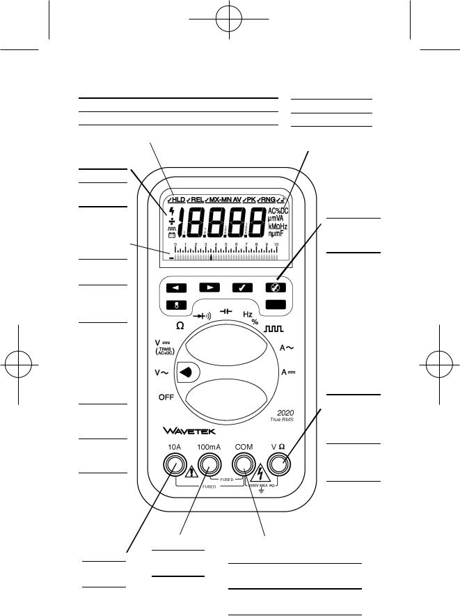
Menu bar – see “Menu Functions”, page xx
Menübalken – siehe “Menüffunktionen”, Seite xx Barra de menú - ver “Funciones de menú”, página xx Barre de menu - voir “Fonctions de Menu”, page xx
5 digit LCD
5 Digit LCD LCD de 5 dígitos LCD 5 digits
41-Segment Bargraph
41-Segment Bargraf Barra analógica de
41 segmentos Bargraphe 41segments
Function/Rang 
e/Off Selector
Funktion- /Bereich-/Aus Schalter
Selector de Función/Escal a/Off
Sélecteur
fonctions/
calibres/march e-arrêt
Unit Indicators
Einheitsanzeigen indicadores de unidades annonciateurs d’unités
Special Function
Buttons
Spezielle
Funktionstasten Teclas de
función especial Boutons de fonctions spéciales
High input for voltage and resistance
VΩ Eingang. Hoch für Spannung und Widerstand Entrada “alta” para tensión y resistencia Entrée VΩ. Haut pour tension et résistance
|
100mA Input |
10 A Input |
100mA Eingang |
10 A Eingang |
Entrada 100mA |
Entrada 10A |
Entrée 100mA |
Entrée 10 A |
|
COM Input – common or low input for all measurements
COM Eingang – Referenzpunkt für alle Messungen
COMentrada común o “baja” para todas las medidas
Entrée COM – commun ou bas pour toutes mesures
– 4 –
2020/30.Man.3x5,25/XPr 19/06/97 14:36 Page 7
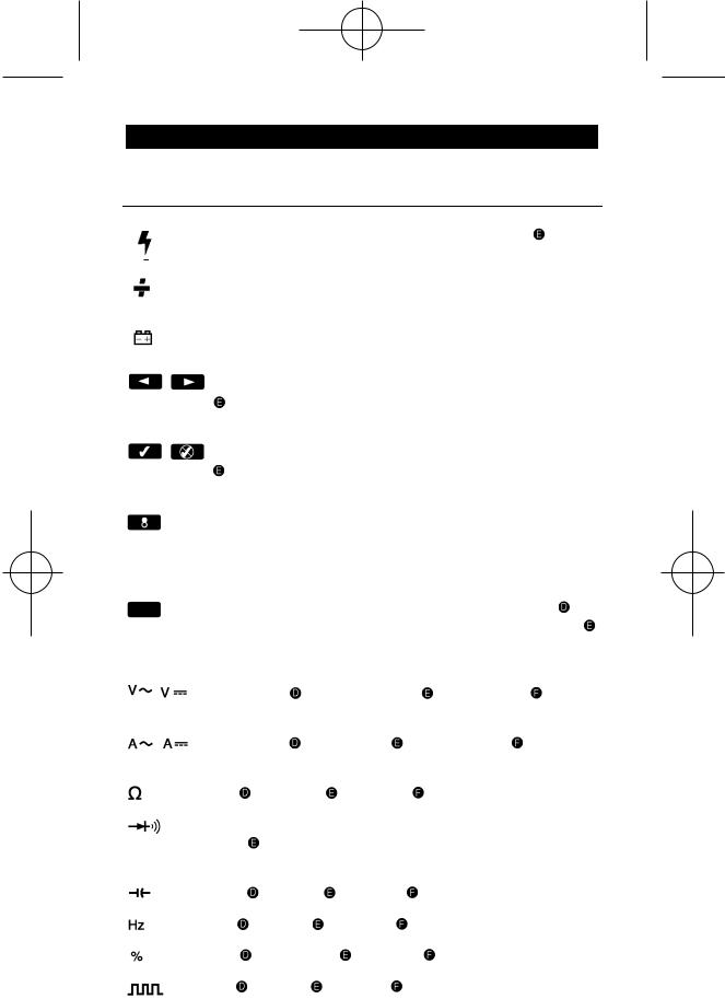
DisplayRangeand Special Function Symbols
 Anzeige-, Bereichsund Funktionssymbole
  Display-, rangeand special function symbols
  Symboles d’affichage, de gammes et de fonctions spéciales
Dangerous voltage warning  Gefährliche Spannungswarnung
Dangerous voltage warning  Avertissement de tension dangereuse
Polarity indication  Polaritätsanzeige
  Indicación de polaridad
Indication de polarité
Low-battery voltage  Entladene Batterieanzeige
  Indicación de “pila baja”
  Low-battery voltage
Menu navigate buttons – left, right  Menüsteuerungstasten – links, rechts Menu navigate buttons – left, right
  Boutons de navigation de menu – gauche, droite
Menu select/deselect button  Menüaktivierungs/-desaktivierungs- tasten Menu select/deselect buttons
  Boutons d’activation et de désactivation de menu
Backlight button ON/OFF. Backlighting turns off after 60 seconds  Rückbeleuchtungstaste (Ein/Aus). Automatische Abschaltung nach 60 Sekunden
  Backlight button ON/OFF. Backlighting turns off after 60 seconds
Bouton de rétro-éclairage. Coupure automatique apès 60 secondes
Second function key. Turns meter back on after automatic shut-down.
Zweite Funktionstaste. Schaltet Gerät ein nach automatischer Abschaltung
Second function buttons. Turns meter back on after automatic shut-down. 
Deuxième bouton de fonction.
AC, DC voltage |
AC, DC Spannnung Tensión CA, CC |
Tension |
|
CA, CC |
|
|
|
AC, DC current |
AC, DC Strom |
Corriente CA, CC |
AC, DC |
current |
|
|
|
Resistance Widerstand Resistencia |
Résistance |
|
|
Diode test and continuity test with beeper  Diodenund Durchgangstest mit Summer Prueba de diodos y de continuidad con zumbador
  Test de diodes et de continuité avec indication sonore
Capacitance |
Kapazität |
|
Capacidad |
|
Capacité |
Frequency |
Frequenz |
Frecuencia |
Fréquence |
||
Duty Cycle |
Taktverhältnis |
Duty Cycle |
Rapport cyclique |
||
Logic Test |
Logiktest |
Logic Test |
Test logique |
||
– 5 –
2020/30.Man.3x5,25/XPr 19/06/97 14:36 Page 8
l’appareil en série avec le circuit – JAMAIS en parallèle avec une source de tension. ■ Remplacez les fusibles toujours par des fusibles équivalents ■ N’utilisez pas cet appareil dans des atmosphères explosives.
PREPARATION FOR USE – UNPACKING
Your shipping carton should include the multimeter, a holster, on e test lead set (one black, one red), one 9V batter y (installed) and this manual. If an y of th e items are d amaged or m iss ing, imm e- diately return the complete package
to the place of purchase for an exchange.
D • Gebrauchsvorbereitung - Auspacken
Die Verpackung sollte enthalten: ein Multimeter, ein Schutzholster, ein Meßkabelsatz (ein schwarz, ein rot), eine 9V Batterie (im Gerät) und diese Anleitung. Wenn ein Teil fehlt oder beschädigt ist, bitte bei der Verkaufsstelle umtauschen.
E • Preparación del multímetro para su uso - Desembalaje
El embalaje debe contener: el multímetro, una funda protectora, un juego de puntas (una negra y otra roja), una pila de 9 V (instalada) y este manual. Si falta algún componente u observa daños, devuelva el conjunto al lugar donde lo adquirió para que se lo cambien.
E • Préparation pour l’Emploi - Déballage
Votre emballage doit contenir: un multimètre, une gaine de protection, un jeu de câbles de mesure (un rouge, un noir), une pile 9V (installée) et ce manuel. Si une pièce manque ou est endommagée, retournez à votre point de vente pur un échange.
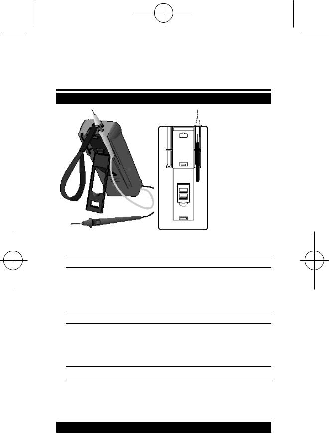
PROTECTIVE HOLSTER
The holster/tilt stand protects the meter from accidental falls and provides greater ease of use. The tilt stand has two positions, and a velcro-strap allows to hang the meter from a fixture. Both test lead probes can be
– 6 –
2020/30.Man.3x5,25/XPr 19/06/97 14:36 Page 9
attached to the holster for storage. One probe can be attached for measurement, holding the meter with probe in one hand and the second probe in the other hand.
D • Schutz-Holster
Das Schutzholster beschirmt das Gerät vor Stürzen und Stößen. Der Kippständer hat zwei Positionen, und mit der Schlaufe können Sie das Gerät aufhängen. Die Meßsonden können am Holster befestigt werden.
E • Funda Protectora
La funda con pie integrado protege el medidor en caso de caídas accidentales. El pie inclinado tiene dos posiciones, y una banda con Velcro permite colgar el multímetro. Las puntas de prueba pueden fijarse a la funda.
F • Holster de Protection
Le holster protège l’appareil contre des chutes accidentelles et des chocs. Il est muni d’une béquille à deux positions et d’une boucle de suspension. Les sondes des cordons peuvent être attachées au holster.
START-UP SEQUENCE
1)The meter shows first all segments of the LCD on. This can be extended by pressing the second function button.
2)The meter performs a battery cut-off test. “bAtt” shows in the display. The bargraph points at the approx. supply voltage. Nominal cut-off point is 5.25 on the scale. If the voltage is lower, “Lobt” is displayed and the meter shuts itself off.
3)The meter goes to the appropriate display for the function selected.
D • Einschaltzyklus
1)Zuerst leuchten alle Anzeigenelemente kurz auf. Durch Drücken der zweiten Funktionstaste kann diese Anzeige verlängert werden.
2)Das Gerät führt einen Batterietest aus. “bAtt” wird angezeigt. Der Bargraf gibt die ungefähre Batteriespannung an. Liegt die Spannung unter 5.25 auf der Bargrafskala, dann wird “Lobt” angezeigt und das Gerät schaltet ab.
3)Die zur gewählten Meßfunktion behörige Anzeige wird angezeigt.
E • Start-up Sequence
1)The meter shows first all segments of the LCD on. This can be extended by pressing the second function button.
2)The meter performs a battery cut-off test. “bAtt” shows in the display. The bargraph points at the approx. supply voltage. Nominal cut-off point is 5.25 on the scale. If the voltage is lower, “Lobt” is displayed and the meter shuts itself off.
3)The meter goes to the appropriate display for the function selected.
–7 –
2020/30.Man.3x5,25/XPr 19/06/97 14:36 Page 10
D • Procédures de Mise en Route
1)A l’allumage l’instrument affiche brièvement tous les éléments de l’afficheur. Cet affichage peut être prolongé en pressant la deuxième touche de fonction.
2)L’instrument vérifie l’étât de chargement de la pile. “bAtt” est affiché et le bargraphe indique la tension approximative. Si le bargraphe indique moins de 5.25 sur son échelle, “Lobt” est affiché et l’appareil s’éteint.
3)L’appareil affiche l’affichage correspondant à la fonction choisie.
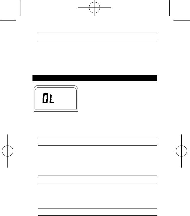
OVERLOAD INDICATION
Range Overload is indicated by “OL” and a continuous tone. Take immediate steps to remove the cause of the overload. Select the next higher range until a value is displayed. If overload still exists in the highest range,
remove test leads from the measurement setup as it is beyond the range of the meter. Overload indication is normal in the OHMS and continuity ranges when the leads are not connected to anything or when the measured value is higher than the selected resistance range.
D • Überlastanzeige
Bereichsüberschreitung wird durch “OL” auf der Anzeige und durch einen Dauerton angezeigt. Ursache der Bereichsüberschreitung sofort entfernen (Höheren Bereich wählen oder Messung unterbrechen). Überlastanzeige ist normal in Widerstandsund Durchgangsbereichen bei offener Schaltung oder zu hohem Widerstand.
E • Indicación de Sobrecarga
La sobrecarga de escala se indica mediante “OL” and a continuous tone. Para eliminar la causa de la sobrecarga, seleccione una escala más alta o interrumpa la medida. La indicación de sobrecarga es normal en medida de OHMS y prueba de continuidad, cuando el circuito está abierto o la resistencia es demasiado alta.
F • Indication de Surcharge
Un dépasssement de calibre est indiqué par “OL” et un ton continu. Ecartez immédiatement la cause du dépassement – choisissez une gamme plus élevée ou interrompez la mesure. L’indication de dépassement est normale dans les gammes de résistance ou de continuité avec circuit ouvert ou résistance trop élevée.
– 8 –
2020/30.Man.3x5,25/XPr 19/06/97 14:36 Page 11
MEASURING PROCEDURES
GENERAL: Turn instrument on by turning function/range switch away from OFF and selecting the parameter you want to measure.
Ranging: This instrument is autoranging on all ranges. It automatically selects the range that gives the best resolution for the measured value. A range can be locked through menu selection (see menu functions). You can tell which range (and function) you are in by the position of the decimal point and the measurement unit displayed.
Bargraph: The 41-segment bargraph indicates at which percentage of the range you presently measure. Like an analog needle display, it is ideal for circuit adjustments.
General Measurement Procedures: ■ When connecting or disconnecting test leads to a circuit, always first turn off power to device or circuit being tested and discharge all capacitors. ■ Strictly observe the max input limits. ■ Do not change functions while test leads are connected to circuit. ■ The display shows dashes until the reading stabilizes.
D • Meßprozeduren
Allgemein: Gerät einschalten durch Funktionsschalter von OFF weg, nach einer gewünschten Meßfunktion zu drehen.
Bereichswahl: Automatisch für alle Funktionen/Bereiche. Aktuelle Funktion und Bereich werden durch Dezimalpunkt und Meßeinheit angezeigt. Sie können einen Bereich festhalten durch Menüwahl (siehe Menüfunktionen).
Bargraph: Der 41-Segment Bargraph zeigt an an welcher Stelle des Bereiches
(%) Sie messen.
Allgemeine Meßprozeduren: ■ Beim Verbinden/Trennen der Meßkabel mit dem/vom Schaltkreis, zuerst Schaltkreis abschalten und Kondensatoren entladen.
■ Eingangsgrenzen beachten. ■ Wahlschalter nicht drehen wenn Meßkabel mit dem Meßkreis verbunden sind. ■ Die Anzeige zeigt Querbalken bis ein stabiler Meßwert erfaßt wird.
E • Procedimientos de medida
EN GENERAL: Encienda el instrumento girando el selector de función/escala en otra posición que no sea OFF, seleccionando el parámetro que desee medir. Selección de escala: Este instrumento selecciona automáticamente la escala (auto-rango) en todas las medidas. La escala y la función seleccionadas en cada momento se indican mediante el punto decimal y la indicación de unidades. A range can be locked through menu selection (see menu functions, page xx) Barra analógica: La barra de 41 segmentos indica el porcentaje del fondo de escala en el que está midiendo en cada momento.
– 9 –

2020/30.Man.3x5,25/XPr 19/06/97 14:36 Page 12
Procedimientos generales de medida: ■ Antes de conectar o desconectar las puntas de prueba a/de un circuito , apague siempre el dispositivo o circuito sometido a pr ueba y descargue todo s los condensad ores. ■ Observe estrictamente los límites máximos de entrada. ■ No cambie de función mientras tenga las puntas de prueba conectadas a un circuito. ■ The display shows dashes until the reading stabilizes.
F • Procédures de Mesure
Général: Mettez l’appareil sous tension en tournant le sélecteur de la position OFF vers la fonction souhaitée.
Sélection de gammes: Automatique pour toutes les fonctions et gammes. La fonction et la gamme en cours sont affichées par le point décimal et l’unité. Vous pouvez bloquer une gamme par sélection de menu (voir “Fonctions de Menu”, page xx).
Bargraphe: Le bargraphe à 41-segments indique à quelle position de la gamme
(%) vous mesurez.
Procédures Générales: ■ Avant de connecter/déconnecter les câbles de mesure à/d’un ciruit, coupez l’alimentation du circuit et déchargez les condensateurs. ■ Ne dépassez pas les limites d’entrée. ■ Ne tournez pas le sélecteur tandis que les cordons sont raccordés à un circuit. ■ L’afficheur montre des traits jusqu’à acquisition d’une valeur stable.
DC AND AC VOLTAGE MEASUREMENT (See Fig. 1)
Connect test leads as shown in figure 1. Turn function selector switch to V  or V
or V  . Touch Probe tips across voltage source (in parallel with circuit). Voltage value will appear on Digital Display along with the voltage polarity (for DC).
Note: If the input exceeds 25V, a lightning bolt appears in the display, coupled with a double beep tone, indicating that the voltage is potentially lethal.
True RMS AC Measurements: Models 2020 and 2030 are ACcoupled True-RMS measuring meters. They measure the true RMS value of distorted AC voltage or current signals. The Crest Factor handling capability is shown in table 1. The Crest Factor is the Peak Value divided by the RMS Value.
True RMS (AC + DC) Measurements: Connect test leads as shown in figure 1. Turn function selector switch to V  . Press second function key to activate true RMS (AC + DC). The AC and DC symbols are displayed. Continue as under step 3 above. The meter range locks for highest AC signal input. If the voltage is too high (OL displayed), select RNG and up range until a reading appears (see Menu Functions).
– 10 –

2020/30.Man.3x5,25/XPr 19/06/97 14:36 Page 13
Fig. 1
Table 1
– 11 –
2020/30.Man.3x5,25/XPr 19/06/97 14:36 Page 14
D • Gleichund Wechselspannungsmessung (siehe Fig.1)
Meßkabel wie in Figur 1 gezeigt verbinden. Funktionsschalter auf V  oder V
  stellen. Meßspitzen mit Meßkreis verbinden – parallel zur Spannungsquelle. Meßwert ablesen (automatische Polaritätsanzeige bei DC Messungen).
Anmerkung: Wenn der Eingang 25V überschreitet, erscheint ein Blitz-Symbol in der Anzeige zusammen mit einem doppelten Biepton, um anzugeben daß die Eingangsspannung lebensgefährlich sein kann.
Echt-Effektivwertmessungen: Modelle 2020 und 2030 sind AC gekoppelte Echt-Effektivwert-messende Geräte. Sie messen den echten Effektivwert, auch von verzerrten Stromund Spannungs-Wellenformen. Der
Crest-Faktorbereich wird in Tabelle 1 gezeigt. Der Crest Faktor ist der Spitzenwert geteilt durch den Effektivwert.
Echt Effektivwert (AC + DC) Messungen: Meßkabel wie in Figur 1 gezeigt verbinden. Funktionsschalter auf V  stellen. Zweite Funktionstaste drücken um Echt-Effektivwertmessung (AC + DC) zu aktivieren. AC und DC Symbole werden angezeigt. Wie unter Punkt 3 oben weiter messen. Das Gerät sperrt den Bereich gemäß höchstem Eingangssignal. Steigt die Spannung über diesen Bereich hinaus (OL Anzeige), höheren Bereich mit RNG Menüfunktion wählen (Siehe Menüfunktionen, Seite xx).
E • Medidas de tensión CC y CA (vea Fig. 1)
Conecte las puntas de prueba como se muestra en la Figura 1. Ponga el selector de función en ACV o DCV. Toque con las puntas de prueba los puntos de tensión (en paralelo con el circuito). Aparece el valor de la tensión en el visualizador digital, junto con la polaridad en l caso de DCV.
Note: If the input exceeds 25V, a lightning bolt appears in the display, coupled with a double beep tone, indicating that the voltage is potentially lethal.
Medidas de verdadero valor eficaz en CA: Los modelos 2020 y 2030 son medidores de verdadero valor eficaz (TRMS), acoplados en CA. Miden el verdadero valor eficaz de señales distorsionadas de tensión o corriente CA. En la Tabla 1 se indica la capacidad de manejo de factores de cresta. El factor de cresta es la tensión de pico dividida por la tensión eficaz.
True RMS (AC + DC) Measurements: Connect test leads as shown in figure 1. Turn function selector switch to V  . Press second function key
to activate true RMS (AC + DC). The AC
and DC symbols are displayed. Continue as under step 3 above. The meter range locks for highest AC signal input. If the voltage is too high (OL displayed), select RNG and up range until a reading appears (see Menu Functions).
F • Mesure de Tensions CC et CA (voir fig. 1)
Connectez les câbles comme indiqué en figure 1. Placez le sélecteur sur VDC (  ) ou VAC (
  ). Connectez les pointes de touche au circuit – en parallèle avec la source de tension. Lisez la valeur.
– 12 –

2020/30.Man.3x5,25/XPr 19/06/97 14:36 Page 15
Note: Quand l’entrée dépasse 25V, un symbole d’éclair est affiché, accompagné d’un double bip sonore. Ceci indique que la tension d’entrée présente un danger mortel.
Mesure effic ace vrai e: Les m odèles 2020 et 2030 sont des instruments à mesure efficace vraie avec couplage CA. Ils mesurent la valeur efficace vraie également de formes d’onde déformées en tension et en courant CA. La figure 1 montre l’évolution du facteur crête. Le facteur crête est la valeur crête divisée par la valeur efficace.
Mesure Efficace Vraie (CA + CC): Connectez les câbles comme indiqué en figure 1. Placez le sélecteur sur V  . Pressez la seconde touche de fonction pour activer la mesure efficace vraie (CA + CC). Les symboles AC (CA) et DC (CC) sont affichés. Continuez comme sous le point 3 plus haut. L’instrument bloque la gamme correspondante à la plus haute valeur d’entrée. Si, par la suite, la valeur d’entrée excède cette gamme (OL affiché), choisissez une gamme plus élevée avec la fonction RNG du menu (voir Fonctions de Menu, page xx).
DC AND AC CURRENT MEASUREMENT (See Fig. 2)
Connect red test lead to the 100mA Input for current measurements up to 100mA or to the 10A input for current measurements to 10A (20A for max 30s)-. Connect black test lead to COM Input Connector. Set the Function Switch to A  or A
or A  as required. Open circuit in which current is to be measured. Securely connect test leads in series with the load. Turn on power to circuit being tested. Read current value on Digital Display.
Incorrect Input Warning: The buzzer sounds when a test lead is connected to current input, but the selector switch is not set to a current range. “FErr” is displayed.
True RMS AC Measurements: Models 2020 and 2030 are ACcoupled True-RMS measuring meters. They measure the true RMS value of distorted AC voltage or current signals. The Crest Factor handling capability is shown in table 1. The Crest Factor is the Peak Voltage divided by the RMS voltage.
True RMS (AC + DC) Measurements: Connect test leads as shown in figure 1. Turn function selector switch to A  . Press second function key to activate true RMS (AC + DC). The AC and DC symbols are displayed. Continue as under step 3 above. The meter range locks for highest AC signal input. If the current is too high (OL displayed), select RNG and up range until a reading appears (see Menu Functions). Eventually change from mA to A input (disconnect meter first).
– 13 –
 Loading...