


W
USER'S HANDBOOK
Model 9100
Universal Calibration System
Volume 2 — Performance
Final Width = 215mm

User's Handbook
For
The Model 9100
Universal Calibration System
Volume 2 — Performance
(for Introduction, Installation, Controls (with Tutorial), Manual Mode and Procedure Mode refer to Volume 1 — Operation)
(for Options 250 and 600 refer to Volume 3 — Operation and Performance)
WForAddressesany assistancecan be foundcontactat yourthe backnearestof thisWavetekhandbook.Sales and Service Center.
ISO 9002
Wavetek Ltd
CERTIFICATE
No. FM 29700
Due to our policy of continuously updating our products, this handbook may contain minor differences in specification, components and circuit design to the instrument actually supplied.
Amendment sheets precisely matched to your instrument serial number are available on request.
Wis a US registered trademark of Wavetek Corporation.

Wavetek Corporation
Standard Warranty Policy
Wavetek warrants that all Products manufactured or procured by Wavetek conform to Wavetek's published specifications and are free from defects in materials and workmanship for a period of one (1) year from the date of delivery to the original Buyer, when used under normal operating conditions and within the service conditions for which they were designed. This warranty is not transferrable and does not apply to used or demonstration products.
The obligation of Wavetek arising from a Warranty claim shall be limited to repairing, or at its option, replacing without charge, any assembly or component (except batteries) which in Wavetek's sole opinion proves to be defective within the scope of the Warranty. In the event Wavetek is not able to modify, repair or replace nonconforming defective parts or components to a condition as warranted within a reasonable time after receipt thereof, Buyers shall receive credit in the amount of the original invoiced price of the product.
Wavetek must be notified in writing of the defect or nonconformity within the Warranty period and the affected Product returned to Wavetek's factory, designated Service Provider, or Authorized Service Center within thirty (30) days after discovery of such defect or nonconformity. Buyer shall prepay shipping charges and insurance for Products returned to Wavetek or its designated Service Provider for warranty service. Wavetek or its designated Service Provider shall pay costs for return of Products to Buyer.
Wavetek shall have no responsibility for any defect or damage caused by improper storage, improper installation, unauthorized modification, misuse, neglect, inadequate maintenance, accident or for any Product which has been repaired or altered by anyone other than Wavetek or its authorized representative or not in accordance with instructions furnished by Wavetek.
The Warranty described above is Buyer's sole and exclusive remedy and no other warranty, whether written or oral, expressed orimplied by statute or course of dealing shall apply. Wavetek specifically disclaims the implied warranties of merchantability and fitness for a particular purpose. No statement, representation, agreement, or understanding, oral or written, made by an agent, distributor, or employee of Wavetek, which is not contained in the foregoing Warranty will be binding upon Wavetek, unless made in writing and executed by an authorized representative of Wavetek. Under no circumstances shall Wavetek be liable for any direct, indirect, special, incidental, or consequential damages, expenses, or losses, including loss of profits, based on contract, tort, or any other legal theory.
April 1, 1994
SAFETY WARNING!
If this equipment is used in a manner not specified by the manufacturer, the protection provided by the equipment may be impaired.
This product complies with the requirements of the following European Community Directives:
89/336/EEC (Electromagnetic Compatibility) and 73/23/EEC (Low Voltage) as amended by 93/68/EEC (CE Marking).
However, noisy or intense electromagnetic fields in the vicinity of the equipment can disturb the measurement circuit. Users should exercise caution and use appropriate connection and cabling configurations to avoid misleading results when making precision measurements in the presence of electromagnetic interference.
© 1998 Wavetek Ltd |
850301 |
Issue 8.0 (June 1998) |

Contents
Final Width = 215mm
|
|
|
Page |
|
Section 1 The Model 9100 Multifunction Calibrator |
See Volume 1 - Operation |
|||
Section 2 |
Installing the Model 9100 |
See Volume 1 - Operation |
||
Section 3 |
Model 9100 Controls |
|
See Volume 1 |
- Operation |
Section 4 |
Using the Model 9100 |
— Manual Mode |
See Volume 1 |
- Operation |
Section 5 |
Using the Model 9100 |
— Procedure Mode |
See Volume 1 |
- Operatio |
Volume 2 — Performance (This Volume)
Section 6 Remote Interfaces |
|
|
6.1 |
About Section 6 ................................................................................................ |
6-1 |
6.2 |
Index of IEEE-488.2 and SCPI Codes used in the Model 9100 ....................... |
6-2 |
6.3 |
Introduction ....................................................................................................... |
6-4 |
6.4 |
Using the Model 9100 in a System ................................................................... |
6-8 |
6.5 |
Retrieval of Device Status Information ............................................................. |
6-15 |
6.6 |
Model 9100 SCPI Language - Commands and Syntax .................................... |
6-24 |
6.7 |
The IEEE Bus Interface for the Power Option .................................................. |
6-58 |
Section 6 Appendix A: IEEE 488.2 Device Documentation Requirements ............... |
6-A1 |
|
Section 6 Appendix B: SCPI Conformance Information ........................................... |
6-B1 |
|
Section 6 Appendix C: IEEE 488.2 Common Commands and Queries |
|
|
|
Implemented in the Model 9100 ........................................... |
6-C1 |
Section 6 Appendix D: Model 9100 — Device Settings after *RST .......................... |
6-D1 |
|
Section 6 Appendix E: Model 9100 — Device Settings at Power On ....................... |
6-E1 |
|
Section 7 Model 9100 Specifications |
|
|
7.1 |
General ............................................................................................................. |
7-1 |
7.2 |
Options and Associated Products .................................................................... |
7-2 |
7.3 |
DC Voltage Specifications ................................................................................ |
7-3 |
7.4 |
AC Voltage Specifications ................................................................................ |
7-4 |
7.5 |
DC Current Specifications ................................................................................ |
7-8 |
7.6 |
AC Current Specifications ................................................................................ |
7-9 |
7.7 |
Resistance Specifications ................................................................................ |
7-14 |
7.8 |
Conductance Specifications ............................................................................. |
7-15 |
7.9 |
Frequency Function Specifications .................................................................. |
7-16 |
7.10 |
Mark/Period Function Specifications ................................................................ |
7-17 |
7.11 |
% Duty Cycle Function Specifications .............................................................. |
7-18 |
7.12 |
Auxiliary Functions - Specifications .................................................................. |
7-19 |
7-13 |
Capacitance Specifications .............................................................................. |
7-20 |
7.14 |
Thermocouple Temperature Specifications ...................................................... |
7-21 |
7.15 |
RTD Temperature Specifications ..................................................................... |
7-22 |
7.16 |
Logic-Pulses Function Specifications ............................................................... |
7-23 |
7.17 |
Logic-Levels Function Specifications ............................................................... |
7-24 |
7.18 |
Insulation/Continuity Specifications .................................................................. |
7-25 |
7.19 |
Power Specifications ........................................................................................ |
7.27 |
0-2 |
Model 9100 User's Handbook — Contents List |

|
|
Page |
Section 8 Model 9100 — Routine Maintenance and Test |
|
|
8.1 |
About Section 8 ................................................................................................ |
8-1 |
8.2 |
Routine Maintenance ....................................................................................... |
8-2 |
8.3 |
Model 9100 Test and Selftest ........................................................................... |
8-10 |
8.4 |
Printing Selftest Results ................................................................................... |
8-26 |
Section 8 Appendix A Error Reporting Subsystem .................................................. |
8-A1 |
|
Section 9 |
Model 9100 — Specification Verification |
|
|
|
9.1 |
About Section 9 ................................................................................................ |
9-1 |
|
|
9.2 |
The Need for Verification .................................................................................. |
9-1 |
|
|
9.3 |
Equipment Requirements ................................................................................. |
9-2 |
|
|
9.4 |
Interconnections ............................................................................................... |
9-2 |
|
|
9.5 |
Verification Points ............................................................................................. |
9-3 |
|
|
9.6 |
Calculating Absolute Specification Limits ......................................................... |
9-4 |
|
|
Section 10 Model 9100 — Calibration |
|
|
||
10.1 |
About Section 10 .............................................................................................. |
10.1-1 |
|
|
10.2 |
The Model 9100 Calibration Mode ................................................................... |
10.2-1 |
|
|
|
10.2.1 |
Introduction ....................................................................................... |
10.2-1 |
|
|
10.2.2 |
Mode Selection ................................................................................. |
10.2-2 |
Final Width = 215mm |
|
10.2.3 |
Selection of Calibration Mode ........................................................... |
10.2-2 |
|
|
10.2.4 |
Special Calibration ............................................................................ |
10.2-5 |
|
|
10.2.5 |
Cold Junction Calibration .................................................................. |
10.2-8 |
|
|
10.2.6 |
Standard Calibration ......................................................................... |
10.2-12 |
|
|
10.2.7 |
Overview of Calibration Operations .................................................. |
10.2-14 |
|
10.3 |
Standard Calibration — Basic Sequences ....................................................... |
10.3-1 |
|
|
|
10.3.1 |
Introduction ....................................................................................... |
10.3-2 |
|
|
10.3.2 |
Selecting Hardware Configurations ................................................... |
10.3-4 |
|
|
10.3.3 |
Selecting Target Calibration Values .................................................. |
10.3-5 |
|
|
10.3.4 |
Calibrating the Model 9100 at Target Values .................................... |
10.3-9 |
|
|
10.3.5 |
Standard Calibration of AC Functions ............................................... |
10.3-13 |
|
10.4 |
Front Panel Calibration by Functions ............................................................... |
10.4-1 |
|
|
|
10.4.1 |
Introduction ....................................................................................... |
10.4-1 |
|
|
10.4.2 |
Summary of Calibration Process ....................................................... |
10.4-2 |
|
|
10.4.3 |
DC Voltage Calibration ...................................................................... |
10.4-6 |
|
|
10.4.4 |
AC Voltage Calibration ...................................................................... |
10.4-14 |
|
|
10.4.5 |
DC Current Calibration ...................................................................... |
10.4-20 |
|
|
10.4.6 |
AC Current Calibration ...................................................................... |
10.4-28 |
|
|
10.4.7 |
Resistance Calibration ...................................................................... |
10.4-36 |
|
|
10.4.8 |
Capacitance Calibration .................................................................... |
10.4-45 |
|
|
10.4.9 |
Insulation Resistance Calibration ...................................................... |
10.4-51 |
|
|
10.4.10 |
Continuity Calibration ........................................................................ |
10.4-57 |
|
10.5 |
Remote Calibration of the Model 9100 via the IEEE 488 Interface .................. |
10.5-1 |
|
|
|
10.5.1 |
The Model 4950 MTS System ........................................................... |
10.5-1 |
|
Model 9100 User's Handbook — Contents List |
0-3 |

Final Width = 215mm
DANGER !
HIGH VOLTAGE
THIS INSTRUMENT IS CAPABLE OF DELIVERING
A LETHAL ELECTRIC SHOCK !
Model 9100: I+, I-, Hi, Lo, sHi and sLo Terminals Model 9105: H (Red), sH (Red), sL (Black) LI- (Black) and I+20 (Yellow) Leads carry the Full Output Voltage
THIS CAN KILL !
Avoid damage to your instrument !
!Refer to User's Handbook, Volume 2, Section 7; for
Maximum Output Voltages and Currents.
Unless you are sure that it is safe to do so, DO NOT TOUCH ANY of the following:
Model 9100: I+ I- Hi Lo sHi or SLo leads and terminals Model 9105: H sH sL LI- or I+20 leads
DANGER

Section 6: 9100 System Application via IEEE-488 Interface
6.1About Section 6
Section 6 describes the environment in which the Model 9100 will operate in remote applications, using the SCPI (Standard Commands for Programmable Instruments) language, within the IEEE-488.1 remote interface. In Section 6 we shall show how the 9100 adopts the IEEE-488.2 message-exchange model and reporting structure, and define the SCPI commands and syntax used to control the 9100. Section 6 is divided into the following sub-sections:
page:
6.2 |
Index of IEEE-488.2 and SCPI Codes used in the 9100 ............................... |
6-2/3 |
6.3Introduction
9100 System Operational Parameters.
6.3.1 |
Interface Capability. ........................................................................ |
6-4 |
6.3.2 |
Interconnections. ............................................................................. |
6-6 |
6.3.3 |
SCPI Programming Language. ....................................................... |
6-7 |
6.4Using the 9100 in a System
9100 System — Infrastructure.
6.4.1 |
Addressing the 9100. ...................................................................... |
6-8 |
Final Width = 215mm |
6.4.2 Operation via the IEEE-488 Interface. ........................................... |
6-10 |
|
|
6.4.3 |
Message Exchange. ......................................................................... |
6-12 |
|
6.4.4 |
Request Service (RQS). .................................................................. |
6-14 |
|
6.5Retrieval of Device Status Information.
9100 'SCPI' Status Reporting Structure, based on IEEE-488.2.
6.5.1 |
General. ........................................................................................... |
6-15 |
|
6.5.2 IEEE-488 and SCPI Standard-Defined Features. ........................... |
6-17 |
||
6.5.3 9100 |
Status Reporting — IEEE-488.2 Basics. ............................... |
6-18 |
|
6.5.4 |
9100 |
Status Reporting — SCPI Elements. ..................................... |
6-23 |
6.69100 SCPI Language — Commands and Syntax.
Detailed treatment of the 9100 SCPI Command Set
6.6.1 |
Introduction. .................................................................................... |
6-24 |
6.6.2 |
CALibration Subsystem .................................................................. |
6-25 |
6.6.3 |
OUTPut Subsystem. ........................................................................ |
6-28 |
6.6.4 |
SOURce Subsystem. ....................................................................... |
6-30 |
6.6.5 |
STATus Subsystem. ........................................................................ |
6-49 |
6.6.6 |
SYSTem Subsystem. ...................................................................... |
6-53 |
Appendix A: |
IEEE 488.2 Device Documentation Requirements. ................. |
6-A1 |
Appendix B: |
SCPI Command Set & Conformance Information. .................. |
6-B1 |
Appendix C: |
IEEE 488.2 Common Commands and Queries. ....................... |
6-C1 |
Appendix D: |
RST (Reset) Conditions. ......................................................... |
6-D1 |
Appendix E: |
Power-on Conditions. .............................................................. |
6-E1 |
Section 6: 9100 System Operation — SCPI Language |
6-1 |

6.2Index of IEEE 488.2 and SCPI Codes used in the 9100
6.2.1Common IEEE 488.2 Commands and Queries
Program Coding |
Description |
Appendix C, Page: |
|
CLS |
Clears event registers and queues (not O/P queue) |
|
6-C1 |
ESE Nrf |
Enables standard-defined event bits |
|
6-C2 |
ESE? |
Returns ESE register mask value |
|
6-C2 |
ESR? |
Reads Event Status register |
|
6-C3 |
IDN? |
Reports manufacturer, model, etc. |
|
6-C4 |
OPC |
Sets the 9100 to monitor the 'No-Operations-Pending' flag. |
|
6-C5 |
OPC? |
For 'No-Operations-Pending' flag 'TRUE', places a 1 in the Output Queue. |
6-C5 |
|
OPT? |
Recalls the instrument's option configuration. |
|
6-C6 |
PSC 0/1 |
Sets/resets power-on status clear flag |
|
6-C7 |
PSC? |
Recalls power-on status clear flag |
|
6-C8 |
PUD |
Allows entry of user data to protected store |
|
6-C9 |
PUD? |
Recalls user-entered data |
|
6-C10 |
RST |
Resets instrument to power on condition |
|
6-C11 / App D, p6-D1 |
SRE Nrf |
Enables Service Request Byte bits |
|
6-C11 |
SRE? |
Returns Service Request Byte mask value |
|
6-C12 |
STB? |
Non-destructively reads Service Request Byte |
|
6-C12 |
TST? |
Perform Full Test |
|
6-C13 |
WAI |
Conforms, but little relevance to 9100 application |
|
6-C14 |
Final Width = 215mm
6-2 |
Section 6: 9100 System Operation — SCPI Language |

6.2.29100 SCPI Subsystems
CALibration |
Used to calibrate the functions and hardware ranges of the 9100, correcting for system errors which have |
|
|
|
accumulated due to drift and ageing effects: ........................................................................................................................ |
6-25 |
|
|
SECure |
:PASSword. Gains access to Calibration operations, using 'Cal Enable' switch and Password. |
|
|
|
:EXIT. Permits clean exit from calibration operation ..................................................................... |
6-25 |
|
TARGet |
Sets up the calibration target point, hardware range (and frequency, where required). ................ |
6-26 |
|
TRIGger? |
Initiates the calibration at a single point, once the target and levels have been set up, |
|
|
|
and returns '0' for pass, and '1' for fail ............................................................................................ |
6-27 |
|
SPECial? |
Runs the DAC characterization and returns '0' for pass, and '1' for fail ......................................... |
6-27 |
|
CJUNction? |
Runs the reference thermocouple junction temperature measurement |
|
|
|
and returns '0' for pass, and '1' for fail ............................................................................................ |
6-27 |
OUTPut |
Used to control parameters associated with output connections: ........................................................................................ |
6-28 |
|
|
[STATe] (?) |
Controls output on/off switching ..................................................................................................... |
6-28 |
|
COMPensation (?) |
Switches the output connections for 4-wire/2-wire in impedance functions ................................... |
6-28 |
|
ISELection (?) |
For Current outputs, selects between front panel terminals (High currents, Current coils), and |
|
|
|
front panel D-type Socket (Low currents) ....................................................................................... |
6-29 |
[SOURce] |
Used to select the main 9100 Function (Voltage, Current etc.), to be output: ...................................................................... |
6-30 |
|
|
FUNCtion |
Selects the Waveshape of output signals ...................................................................................... |
6-32 |
|
VOLTage |
Selects the Voltage source for output ............................................................................................ |
6-34 |
|
CURRent |
Selects the Current source for output ............................................................................................ |
6-36 |
|
RESistance |
Selects the Resistance source for output ....................................................................................... |
6-37 |
|
CONDuctance |
Selects the Conductance source for output ................................................................................... |
6-38 |
|
CAPacitance |
Selects the Capacitance source for output .................................................................................... |
6-39 |
|
FREQuency |
Controls the Output Frequency value for AC functions .................................................................. |
6-40 |
|
PHASe |
Selects and controls the Phase-shifting facility .............................................................................. |
6-41 |
|
PULSe |
Selects and controls the Pulse source for output ........................................................................... |
6-43 |
|
TEMPerature |
Selects and controls the Temperature sources for output ............................................................. |
6-44 |
STATus |
Gives access to the 9100 SCPI-defined Status Reporting Structure: .................................................................................. |
6-49 |
|
|
OPERation |
Reads from, or writes to, the OPERation Status Register ............................................................. |
6-49 |
|
QUEStionable |
Reads from, or writes to, the QUEStionable Status Register ......................................................... |
6-51 |
|
PRESet |
Presets a default status reporting condition ................................................................................... |
6-52 |
SYSTem |
Collects general functions that are not related to 9100 performance: .................................................................................. |
6-53 |
|
|
ERRor? |
Requests the next entry from the 9100 error queue. ..................................................................... |
6-53 |
|
DATE(?) |
Reads or writes the present date ................................................................................................... |
6-54 |
|
TIME(?) |
Reads or writes the present time ................................................................................................... |
6-55 |
|
SVOLtage(?) |
Reads or writes the Safety Threshold Voltage in DC or AC Voltage function ................................ |
6-56 |
|
VERSion? |
Returns a numeric value corresponding to the SCPI version for which the instrument complies .. |
6-56 |
Final Width = 215mm
Section 6: 9100 System Operation — SCPI Language |
6-3 |

|
IEEE |
|
|
488.1 |
Interface Function |
|
Subset |
|
|
|
|
|
SH1 |
Source Handshake Capability |
Final Width = 215mm |
AH1 |
Acceptor Handshake |
|
Capability |
|
|
|
|
|
T6 |
Talker (basic talker, serial |
|
|
poll, unaddressed to talk if |
|
|
addressed to listen) |
|
L4 |
Listener (basic listener, |
|
|
unaddressed to listen if |
|
|
addressed to talk) |
|
SR1 |
Service Request Capability |
|
RL1 |
Remote/Local Capability (incl. |
|
|
Local Lockout) |
|
PP0 |
No Parallel Poll Capability |
|
DC1 |
Device Clear Capability |
|
DT0 |
No Device Trigger Capability |
|
C0 |
No Controller Capability |
|
E2 |
Open-Collector and Three- |
|
|
State Drivers |
|
|
|
Table 6.1
IEEE 488.1 Interface Capability
6.3Introduction
This first part of Section 5 gives the information necessary to put the 9100 into operation on the IEEE 488 bus. For more detailed information, refer to the standard specification in the publications ANSI/IEEE Std. 488.1-1987 and IEEE Std. 488.2-1988.
6.3.1Interface Capability
6.3.1.1IEEE Standards 488.1 and 488.2
The 9100 conforms to the Standard Specification IEEE 488.1-1987: ‘IEEE Standard Digital Interface for Programmable Instrumentation’, and to IEEE 488.2-1988: ‘Codes, Formats, Protocols and Common Commands’.
6.3.1.2The 9100 in IEEE 488.2 Terminology
In IEEE 488.2 terminology the 9100 is a device containing a system interface. It can be connected to a system via its system bus and set into programmed communication with other bus-connected devices under the direction of a system controller.
6.3.1.3Programming Options
The instrument can be programmed via the IEEE Interface, to:
•Change its operating state (Function, Range, etc).
•Transmit its own status data over the bus.
•Request service from the system controller.
6.3.1.4Capability Codes
To conform to the IEEE 488.1 standard specification, it is not essential for a device to encompass the full range of bus capabilities. For IEEE 488.2, the device must conform exactly to a specific subset of IEEE 488.1, with a minimal choice of optional capabilities.
The IEEE 488.1 document describes and codes the standard bus features, for manufacturers to give brief coded descriptions of their own interfaces’ overall capability. For IEEE 488.2, this description is required to be part of the device documentation. A code string is often printed on the product itself.
The codes which apply to the 9100 are given in table 6.1, together with short descriptions. They also appear on the rear of the instrument next to the interface connector. These codes conform to the capabilities required by IEEE 488.2.
Appendix C of the IEEE 488.1 document contains a fuller description of each code.
6-4 |
Section 6: 9100 System Operation — SCPI Language |
6.3.1.5Bus Addresses
When an IEEE 488 system comprises several instruments, a unique ‘Address’ is assigned to each to enable the controller to communicate with them individually.
Only one address is required for the 9100. The application program adds information to it to define ‘talk’ or ‘listen’. The method of setting the address, and the point at which the user-initiated address is recognized by the 9100, is given in Sub-Section 6.4.1.
The 9100 has a single primary address, which can be set by the user to any value within the range from 0 to 30 inclusive. It cannot be made to respond to any address outside this range. Secondary addressing is not available.
6.3.1.6Limited Access
The 9100 has five main modes, which are described briefly in Volume 1 of this Handbook, Section 1, Sub-section 1.2.2. Remote operation is available only subject to the following limitations:
•Procedure Mode
When the 9100 is in Procedure Mode, it is driven essentially from the front panel.
Remote Operation will not be allowed in this mode.
Final Width = 215mm
N.B. The 9100 can be powered up in either Manual mode or Procedure mode, as set locally in Configuration mode.
•Manual Mode
Remote operation is available for each Manual mode function, but for ease of programming, some remote commands do not mirror front panel operations exactly.
•Configuration Mode
Remote operation is not available, and configuration commands have not been included in the SCPI command set for the 9100.
•Calibration Mode
Remote operation is available, but refer to Sub-section 6.6.2 for details of entry protection.
•Test Mode
Remote operation is not available, but the 'Full' selftest can be initiated by a SCPI command. The 9100 will give a straight Pass/Fail response, but to investigate further, it will be necessary to re-run the test in Test mode from the front panel.
Section 6: 9100 System Operation — SCPI Language |
6-5 |

6.3.2 |
|
Interconnections |
|
|
|
|
|
|
|||
Instruments fitted with an IEEE 488 |
|
|
|
|
|
|
|||||
interface communicate with each other |
|
|
|
|
|
|
|||||
through a standard set of interconnecting |
|
|
|
|
|
|
|||||
cables, as specified in the IEEE 488.1 |
|
|
12 |
1 |
|
|
|||||
Standard document. |
|
|
|
|
|
||||||
|
|
|
|
|
|
|
|||||
|
|
|
|
|
|
|
|
|
|
|
|
The IEEE-488 interface socket, J101, is |
|
|
24 |
13 |
|
|
|||||
|
|
|
|
|
|
||||||
fitted on the rear panel. It accommodates |
|
|
|
|
|
|
|||||
|
|
|
|
|
|
||||||
the |
specified connector, whose pin |
Connector J101 - Pin Layout |
|||||||||
designations are also standardized as |
|||||||||||
|
|
|
|
|
|
||||||
shown in Table 6.2 |
|
|
|
|
|
|
|
||||
|
|
Pin |
|
|
|
|
|
|
|
|
|
|
|
No. |
Name |
Description |
|
|
|
|
|
|
|
|
|
|
|
|
|
|
|
|
|
|
|
|
1 |
DIO 1 |
Data Input/Output Line 1 |
|
|
|
|
|
|
||
|
2 |
DIO 2 |
Data Input/Output Line 2 |
|
|
|
|
|
|
||
|
3 |
DIO 3 |
Data Input/Output Line 3 |
|
|
|
|
|
|
||
|
4 |
DIO 4 |
Data Input/Output Line 4 |
|
|
|
|
|
|
||
Final Width = 215mm |
5 |
EOI |
End or Identify |
|
|
|
|
|
|
||
|
6 |
DAV |
Data Valid |
|
|
|
|
|
|
||
|
7 |
NRFD |
Not Ready For Data |
|
|
|
|
|
|
||
|
8 |
NDAC |
Not Data Accepted |
|
|
|
|
|
|
||
|
9 |
IFC |
Interface Clear |
|
|
|
|
|
|
||
|
10 |
SRQ |
Service Request |
|
|
|
|
|
|
||
|
11 |
ATN |
Attention |
|
|
|
|
|
|
||
|
12 |
SHIELD |
Screening on cable (connected to 9100 safety ground) |
||||||||
|
13 |
DIO 5 |
Data Input/Output Line 5 |
|
|
|
|
|
|
||
|
14 |
DIO 6 |
Data Input/Output Line 6 |
|
|
|
|
|
|
||
|
15 |
DIO 7 |
Data Input/Output Line 7 |
|
|
|
|
|
|
||
|
16 |
DIO 8 |
Data Input/Output Line 8 |
|
|
|
|
|
|
||
|
17 |
REN |
Remote Enable |
|
|
|
|
|
|
||
|
18 |
GND 6 |
Gnd wire of DAV twisted pair |
|
|
|
|
||||
|
19 |
GND 7 |
Gnd wire of NRFD twisted pair |
|
|
|
|
||||
|
20 |
GND 8 |
Gnd wire of NDAC twisted pair |
|
|
|
|
||||
|
21 |
GND 9 |
Gnd wire of IFC twisted pair |
|
|
|
|
||||
|
22 |
GND 10 |
Gnd wire of SRQ twisted pair |
|
|
|
|
||||
|
23 |
GND 11 |
Gnd wire of ATN twisted pair |
|
|
|
|
||||
|
24 |
GND |
9100 Logic Ground (internally connected to Safety Ground) |
||||||||
|
|
|
|
|
|
|
|
|
|
|
|
Table 6.2 Connector J101 - Pin Designations
6-6 |
Section 6: 9100 System Operation — SCPI Language |

6.3.3SCPI Programming Language
Standard Commands for Programmable Instruments (SCPI) is an instrument command language which goes beyond IEEE 488.2 to address a wide variety of instrument functions in a standard manner.
IEEE 488.2 defines sets of Mandatory Common Commands and Optional Common Commands along with a method of Standard Status Reporting. The 9100 implementation of SCPI language conforms with all IEEE-488.2 Mandatory Commands but not all Optional Commands. It conforms with the SCPI-approved Status Reporting method.
Note: Commands in SCPI language, prefaced by an asterisk (eg: CLS), are IEEE-488.2 standard-defined ‘Common’ commands.
Conformance of the 9100 remote programming commands to SCPI ensures that the 9100 has a high degree of consistency with other conforming instruments. For most specific commands, such as those relating to frequency and voltage, the SCPI approved command structure already exists and has been used wherever possible.
SCPI commands are easy to learn, self-explanatory and account for a wide variety of usage skills. A summary of the 9100 commands is given on pages 6-2 and 6-3. The full range of 9100 commands, with their actions and meanings in the 9100, is detailed in
alphabetical order in Sub-Section 6-6.
Final Width = 215mm
Section 6: 9100 System Operation — SCPI Language |
6-7 |
|
|
|
|
|
|
|
|
|
|
|
6.4 |
Using the 9100 in a System |
|
|
|
||
|
|
6.4.1 |
Addressing the 9100 |
|
|
|
|
|
|
|
6.4.1.1 |
Accessing the Bus Address |
|
|
|
||
|
|
The instrument address can only be set manually; using the Bus Address menu, which |
||||||
|
|
is accessed via the Configuration menus. |
|
|
|
|
||
|
|
N.B. A password is required for access to change the bus address. |
|
|
||||
|
|
6.4.1.2 |
Select 'Configuration' Mode |
|
|
|
||
|
|
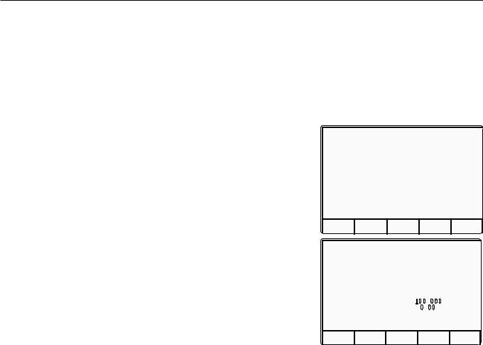
1. Press the Mode key on the right of the |
|
|
|
|
||
|
|
|
front panel to obtain the 'Mode |
Mode Selection |
||||
|
|
|
Selection' menu screen: |
|||||
|
|
|
Select required mode using softkeys |
|||||
|
|
|
|
|
||||
|
|
2. Press the CONFIG screen key at the |
|
|
|
|
||
|
|
|
center of the bottom row to progress |
|
|
|
|
|
|
|
|
into 'Configuration' mode. The 9100 TODAYS DATE |
TIME |
|
|
||
Final Width = 215mm |
|
will transfer to the open 'Configuration' |
PROC MANUAL |
CONFIG CALIB TEST |
||||
|
|
|
|
|
||||
|
menu screen: |
|
|
|
|
|||
|
|
|
Configuration |
|||||
|
|
|
|
|
||||
|
|
|
|
|
Ser. No. XXXXXX |
Rev. XXX |
||
|
|
|
|
|
Present Settings: |
|
|
|
|
|
|
|
|
Language |
English |
|
|
|
|
|
|
|
Power-up mode |
Manual |
|
|
|
|
|
|
|
Bus Address |
1 |
|
|
|
|
|
|
|
Printer |
NONE |
|
|
|
|
|
|
|
Results Card |
Disabled |
||
|
|
|
|
|
Safety Voltage |
. |
V |
|
|
|
|
|
|
Border Line |
7 . |
% |
|
|
|
|
|
|
Scope option |
Option 600 |
||
|
|
|
|
|
Crystal option |
High acc |
||
|
|
|
|
|
TODAYS DATE |
TIME |
|
|
|
|
|
|
|
V I E W |
|
M O R E |
|
|
|
6.4.1.3 |
Select 'MORE' Parameters |
|
|
|
||
|
|
The bus address is one of the 'MORE' parameters. By trying to select 'MORE', the |
||||||
|
|
'Configuration' password will be required. |
|
|
|
|
||
|
|
|
Press the MORE screen key on the right of the bottom row. The 9100 will transfer |
|||||
|
|
|
to the 'Password Entry' screen. |
|
|
|
|
|
|
|
|
|
|
|
|
|
|
|
|
|
|
|
|
|
|
|
6-8 |
Section 6: 9100 System Operation — SCPI Language |

Note: Address Recognition
With an address selected in the range 0 to 30; control may be manual, or remote as part of a system on the Bus. The address must be the same as that used in the controller program to activate the 9100. The 9100 is always aware of its stored address, responding to Talk or Listen commands from the controller at that address. When the address is changed by the user, the 9100 recognizes its new address and ignores its old address, as soon as it is stored by the user pressing the EXIT key in the
Configuration — Bus Address menu.
6.4.1.4Enter Your Password
1.When you enter your password using the alpha-numeric keyboard, security
icons will appear on the screen as you type. Finally press the (return) key.
If the password is incorrect: an error message will be given and the security icons will be removed, enabling a new attempt to enter the password.
The 'EXIT' screen key acts to escape, back to the previous screen.
Password Entry
For Configuration
Enter password :
TODAYS DATE |
TIME |
E X I T
2. The correct password, followed by , will provide entry to the main 'Configuration' menu screen, which shows the present settings of the parameters which can be changed using screen keys on this display:
3. In this case we are interested in 'BUS ADDRESS'.
6.4.1.5Change the Bus Address
Configuration
Ser. No. XXXXXX |
Rev. XXX |
||
Present Settings: |
|
|
|
Language |
|
English |
|
Power-up mode |
Manual |
|
|
Bus Address |
1 |
|
|
Printer |
|
NONE |
|
Results Card |
Disabled |
||
Safety Voltage |
. |
V |
|
Border Line |
7 . |
% |
|
Scope option |
Option 600 |
||
Crystal option |
High acc |
||
TODAYS DATE |
|
TIME |
|
V O L T A G E |
D A T E |
B O R D E R |
|
L I M I T |
T I M E |
L I N E |
|
1. For access from the 'Present Settings' screen, press the BUS ADDRESS screen key on the right. This action will transfer to the 'Change the address' screen:
The 9100 IEEE-488 bus address can be set to any number within the range 0 to 30.
2. Use Digit edit or Direct edit to set the required bus address number. If using Direct edit, after typing the number press the key.
3. Press EXIT to return to the 'Present Settings' screen.
Configuration
Change the address by using digit or direct editing.
Bus address = 22
TODAYS DATE |
TIME |
E X I T
S E L E C T
L A N G
P O W E R
U P M O D E
B U S
A D D R E S S
P R I N T E R |
|
R E S U L T S |
Final Width = 215mm |
C A R D |
C L E A R
U S E R
L I S T
M O R E
Section 6: 9100 System Operation — SCPI Language |
6-9 |

|
|
6.4.2 |
Operation via the IEEE-488 Interface |
||
|
|
6.4.2.1 |
General |
||
|
|
The power-up sequence is performed as in local operation. The 9100 can be programmed |
|||
|
|
to generate an SRQ at power-up, also preparing a status response for transmission to the |
|||
|
|
controller when interrogated by a subsequent serial poll. |
|||
|
|
6.4.2.2 |
Operating Conditions |
||
|
|
When the 9100 is operating under the direction of the application program, there are two |
|||
|
|
main conditions, depending on whether the application program has set the 'REN' |
|||
|
|
management line 'true' or 'false': |
|||
|
|
1. REN True ('REN' line low): |
|||
|
|
The 9100 can be addressed and commanded if in either 'Manual' or 'Calibration' mode. |
|||
|
|
All access to front panel control will be removed, except for the bottom right screen |
|||
|
|
key, labelled 'Enable Local Usage'. The cursor controls will not be present. |
|||
|
|
If LLO (Local Lockout) has been sent with REN true, then the 'Enable Local Usage' |
|||
|
|
screen key will be inoperative. If LLO has not been sent, the 'Enable Local Usage' |
|||
|
|
screen key will return to local control as if REN were false (see 2 below). |
|||
Final Width = 215mm |
The 9100 will act in response to valid commands, performing any changes in output, |
||||
etc. The display presentation will track the changes. |
|||||
|
|
||||
|
|
Remote control cannot command 'Configuration' mode or 'Procedure' mode. These |
|||
|
|
are Local Modes only. Remote control cannot break into locally-entered 'Configuration' |
|||
|
|
mode, 'Procedure' mode or 'Test' mode. However, 'Test' can be run remotely. |
|||
|
|
2. REN False ('REN' line high): |
|||
|
|
The 9100 will remain in Local Operation, but can be addressed and commanded, |
|||
|
|
while full access to front panel control is also retained. |
|||
|
|
The 9100 will act in response to the commands, performing any changes in output, etc. |
|||
|
|
These changes will occur rapidly enough for the only noticeable effect to be the |
|||
|
|
display presentation tracking the changes. |
|||
|
|
6.4.2.3 |
Programmed Transfer to Local Control (GTL or REN False) |
||
|
|
The application program can switch the 9100 into ‘Local’ Control (by sending Command |
|||
|
|
GTL, or by setting the REN line false), permitting a user to take manual control from the |
|||
|
|
front panel. |
|
|
|
|
|
The application program can regain ‘Remote’ control by sending the overriding command: |
|||
|
|
Listen Address with REN true (addressing the 9100 as a listener with the Remote Enable |
|||
|
|
management line true {Low}). This will re-impose remote control, unless the 9100 is in |
|||
|
|
Configuration, Procedure or Test Mode. |
|||
|
|
|
|
|
|
|
|
|
|
|
|
6-10 |
Section 6: 9100 System Operation — SCPI Language |

6.4.2.4‘Device Clear’
Either of the commands DCL or SDC will force the following instrument states:
•all IEEE 488 input and output buffers cleared;
•with 'IFC' (Interface Clear), any device-dependent message bus holdoffs cleared.
•the status byte is changed by clearing the MAV bit.
These commands will not:
•change any settings or stored data within the device except as listed above;
•interrupt analog output;
•interrupt or affect any functions of the device not associated with the IEEE 488 system;
6.4.2.5Levels of Reset
Three levels of reset are defined for IEEE 488.2 application programs, a complete system reset being accomplished by resetting at all three levels, in order, to every device. In other circumstances they may be used individually or in combination:
IFC |
Bus initialization; |
|
DCL |
Message exchange initialization; |
|
RST Device initialization. |
Final Width = 215mm |
|
The effects of the RST command are described in Appendix C to this section.
Section 6: 9100 System Operation — SCPI Language |
6-11 |
6.4.3Message Exchange
6.4.3.1IEEE 488.2 Model
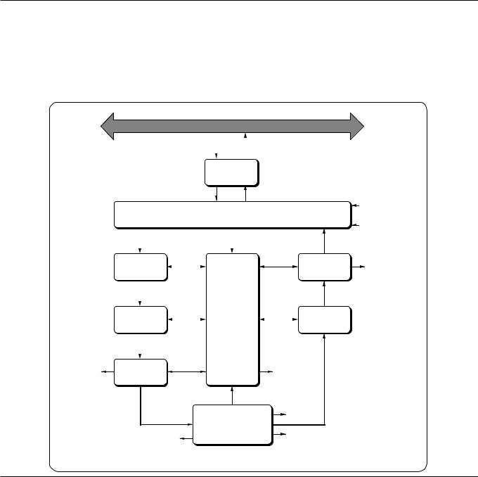
The IEEE 488.2 Standard document illustrates its Message Exchange Control Interface model at the detail level required by the device designer. Much of the information at this level of interpretation (such as the details of the internal signal paths etc.) is transparent to the application programmer. However, because each of the types of errors flagged in the Event Status Register is related to a particular stage in the process, a simplified 9100 interface model can provide helpful background. This is shown below in Fig. 6.1, together with brief descriptions of the actions of its functional blocks.
|
IEEE 488.1 bus |
|
|
|||
Bus |
|
|
|
9100 Bus |
||
|
|
|
||||
Messages |
|
|
Transmissions |
|||
|
|
|
|
|
|
|
|
|
IEEE-488-1 |
|
Filter out bus management and |
||
|
Bus Interface |
|
configuration commands |
|||
Final Width = 215mm
General and Addressed
Bus Messages
Input
Buffer
Received
Message
Elements
Command
Errors  Parser (CME bit)
Parsed
Message
Elements
Execution |
Execution |
|
Errors |
||
Control |
||
(EXE bit) |
||
|
Executable
Message
Elements
Device-Dependent
Errors (DDE bit)
|
Status Byte |
|
Input/Output Control |
(STB) |
|
RQS bit state |
||
|
||
|
for Status Byte |
|
Requested |
|
|
Bus Messages |
|
|
Output |
Message |
|
Available |
||
Queue |
||
(MAV bit) |
||
|
Response
Message
Elements
Message |
Response |
|
Exchange |
||
Formatter |
||
Control |
||
|
Query Errors
(QYE bit)
Response
Data
Power On
(PON bit)
9100 Functions
and Facilities
(URQ bit)
Fig. 6.1 9100 Message Exchange Model
6-12 |
Section 6: 9100 System Operation — SCPI Language |

Note: Coupled Commands
Coupled commands are best described by an example:
In Section 7, on pages 7-5 and 7-10, the 'Volt-Hz' and 'Amp-Hz' profiles are given. In the 9100, no AC output can be generated whose product of amplitude and frequency occurs outside the relevant profile.
With sequential execution of commands a change in amplitude and frequency (e.g.:VOLT 121;:FREQ 10E3 - a setting within the profile) would cause an execution error if the present frequency was 50kHz, as the combination of 121V and 50kHz is outside the profile
Such anomalies are overcome by defining a coupling between commands which allows the execution of the individual components to be deferred until all contiguous coupled commands in the same group have been parsed and the validity of the combination checked
Note that this does not require that all the coupled components in a group must be supplied for each new signal but that those programmed will be correctly parsed.
Individual commands may be a member of several coupled command groups. Refer to Appendix A to this Section, page 6-A1, for details of coupled groups.
6.4.3.29100 STATUS Subsystem
Input/Output Control transfers messages from the 9100 output queue to the system bus; and conversely from the bus to either the input buffer, or other predetermined destinations within the device interface. It receives the Status Byte from the status reporting system, as well as the state of the Request Service bit which it imposes on bit 6 of the Status Byte response. Bit 6 reflects the ‘Request Service state true’ condition of the interface.
6.4.3.3Incoming Commands and Queries
The Input Buffer is a first in - first out queue, which has a maximum capacity of 128 bytes (characters). Each incoming character in the I/O Control generates an interrupt to the instrument processor which places it in the Input Buffer for examination by the Parser. The characters are removed from the buffer and translated with appropriate levels of syntax checking. If the rate of programming is too fast for the Parser or Execution Control, the buffer will progressively fill up. When the buffer is full, the handshake is held.
The Parser checks each incoming character and its message context for correct Standarddefined generic syntax, and correct device-defined syntax. Offending syntax is reported as a Command Error, by setting true bit 5 (CME) of the Standard-defined Event Status register (refer to Sub-Section 6.5 ‘Retrieval of Device Status Information’) .
Execution Control receives successfully parsed messages, and assesses whether they can be executed, given the currently-programmed state of the 9100 functions and facilities. If a message is not viable then an Execution Error is reported, by setting true bit 4 (EXE) of the Standard-defined Event Status register. Viable messages are executed in order, altering the 9100 functions, facilities etc. Execution does not ‘overlap’ commands; instead, the 9100 Execution Control processes all commands or coupled groups of commands (see Note in left column) ‘sequentially’ (ie. waits for actions resulting from the previous command to complete before executing the next).
6.4.3.49100 Functions and Facilities
The 9100 Functions and Facilities block contains all the device-specific functions and features of the 9100, accepting Executable Message Elements from Execution Control and performing the associated operations. It responds to any of the elements which are valid Query Requests (both IEEE 488.2 Common Query Commands and 9100 Devicespecific Commands) by sending any required Response Data to the Response Formatter (after carrying out the assigned internal operations).
Device-dependent errors are detected in this block. Bit 3 (DDE) of the Standard Event Status register is set true when an internal operating fault is detected. Each reportable error number is appended to the Error Queue as the error occurs.
Final Width = 215mm
Section 6: 9100 System Operation — SCPI Language |
6-13 |

6.4.3.5 Outgoing Responses
The Response Formatter derives its information from Response Data (being supplied by the Functions and Facilities block) and valid Query Requests. From these it builds Response Message Elements, which are placed as a Response Message into the Output Queue.
The Output Queue acts as a store for outgoing messages until they are read over the system bus by the application program. For as long as the output queue holds one or more bytes, it reports the fact by setting true bit 4 (Message Available - MAV) of the Status Byte register. Bit 4 is set false when the output queue is empty (refer to Sub-Section 6.5 ‘Retrieval of Device Status Information’) .
6.4.3.6 ‘Query Error’
This is an indication that the application program is following an inappropriate message exchange protocol, resulting in the Interrupted, Unterminated or Deadlocked condition:
Refer to 'Bit 2' inparas 6.5.3.5.
The Standard document defines the 9100’s response, part of which is to set true bit 2
(QYE) of the Standard-defined Event Status register.
Final Width = 215mm
6.4.4 Request Service (RQS)
6.4.4.1 Reasons for Requesting Service
There are two main reasons for the application program to request service from the controller:
• When the 9100 message exchange interface is programmed to report a system programming error;
• When the 9100 is programmed to report significant events by RQS.
The significant events vary between types of devices; thus there is a class of events which are known as ‘Device-Specific’. These are determined by the device designer.
6.4.4.2 RQS in the IEEE 488.2 Model
The application programmer can enable or disable the event(s) which are required to originate an RQS at particular stages of the application program. The IEEE 488.2 model is extended to incorporate a flexible SCPI status reporting structure in which the requirements of the device designer and application programmer are both met.
This structure is described in Sub-Section 6.5, dealing with ‘Retrieval of Device Status
Information’.
6-14 |
Section 6: 9100 System Operation — SCPI Language |
6.5Retrieval of Device Status Information
6.5.1General
For any remotely-operated system, the provision of up-to-date information about the performance of the system is of major importance. In the case of systems which operate under automatic control, the controller requires the necessary feedback to enable it to progress the task; any break in the continuity of the process can have serious results.
When developing an application program, the programmer needs to test and revise it, knowing its effects. Confidence that the program elements are couched in the correct grammar and syntax (and that the program commands and queries are thus being accepted and acted upon), helps to reduce the number of iterations needed to confirm and develop the viability of the whole program. So any assistance which can be given in closing the information loop must benefit both program compilation and subsequent use.
Such information is given in the following pages.
Final Width = 215mm
Section 6: 9100 System Operation — SCPI Language |
6-15 |

SCPI Status Structure Registers |
IEEE 488.2 Status Structure Registers |
|
Summary Bit — OSS |
|
|
|
|
|
Operation |
|
|
|
|
|
Status |
Operation Status |
|
|
|
|
Register |
|
|
|
|
|
|
Enable Register |
|
|
|
|
bit 15 |
|
|
|
|
|
bit 14 |
|
|
|
|
Not Used |
bit 13 |
|
|
|
|
in 9100 |
bit 12 |
|
|
|
|
|
bit 11 |
|
|
|
|
PRETESTING |
bit 10 |
|
|
|
|
bit 9 |
|
|
|
|
|
|
|
|
|
|
|
TESTING |
bit 8 |
|
|
|
|
bit 7 |
|
|
|
|
|
|
|
|
|
|
|
|
bit 6 |
|
|
|
|
Not Used |
bit 5 |
|
|
|
|
bit 4 |
|
|
Status Byte |
|
|
in 9100 |
|
|
|
||
|
bit 3 |
|
|
Register |
Service Request |
|
bit 2 |
|
|
|
Enable Register |
|
bit 1 |
|
|
bit 7 |
|
|
bit 0 |
|
|
|
|
CALIBRATING |
|
|
OSS |
|
|
|
|
|
Master Status Summary Bit |
bit |
|
|
|
|
Request for Service Bit |
MSS RQS |
|
|
OPERation: |
|
bit 5 |
|
|
|
ENABle ? |
|
|
||
|
Summary Bit — ESB |
ESB |
|
||
|
OPERation: |
OPERation: |
|
||
|
|
bit 4 |
|
||
|
EVENt ? |
ENABle <DNPD> |
|
|
|
Final Width = 215mm |
MAV |
|
|
|
|
|
|
|
bit 3 |
|
|
Summary Bit — QSS |
|
|
|
|
QSS |
|
|
|
|
|
|
|
|
|
bit 2 |
|
|
Questionable |
|
Standard- |
|
|
|
|
|
|
Questionable |
Defined |
|
|
Not Used |
bit 1 |
|
|
|
Status |
|
|
|
||||
|
Event Status |
Event Status |
|
|||||
|
Register |
Status |
in 9100 |
|
|
|||
|
|
Enable Register |
Register |
|
Enable Register |
|
bit 0 |
|
|
|
|
|
|
|
|
|
|
|
bit 15 |
|
bit 7 |
|
|
|
|
|
Not Used |
bit 14 |
Power On |
PON |
|
|
|
|
|
bit 13 |
Not Used |
bit 6 |
|
|
|
|
|
|
in 9100 |
|
|
|
|
|
|||
bit 12 |
in 9100 |
URQ |
|
|
|
|
|
|
|
|
|
|
STB? |
SRE? |
|||
|
|
|
|
|
|
|||
|
bit 11 |
|
bit 5 |
|
|
|
||
INV OHM CURR2 |
|
|
|
|
|
|
||
bit 10 |
Command Error |
CME |
|
|
|
|
|
|
|
|
|
|
|
SRE phs Nrf |
|||
INV OHM CURR1 |
bit 9 |
|
bit 4 |
|
|
|
|
|
bit 8 |
Execution Error |
EXE |
|
|
|
|
|
|
|
|
|
|
|
|
|||
Not Used |
bit 7 |
|
bit 3 |
|
|
|
|
|
in 9100 |
bit 6 |
Device-Dependent Error |
DDE |
|
|
|
|
FIFO |
|
bit 5 |
|
bit 2 |
|
|
|
|
|
|
|
|
|
|
|
|
||
TEMPerature |
bit 4 |
Query Error |
QYE |
|
|
|
|
|
bit 3 |
Not Used |
bit 1 |
|
|
|
|
|
|
|
|
|
|
|
|
|||
Not Used |
bit 2 |
in 9100 |
RQC |
|
|
Message Available Bit — MAV |
|
|
|
|
|
|
|
||||
in 9100 |
bit 1 |
|
bit 0 |
|
|
(True if one or more |
Output |
|
|
bit 0 |
Operation Complete |
OPC |
|
|
messages are present in |
||
|
|
|
|
|
|
the Output Queue) |
|
Queue |
|
QUEStionable: |
ESR? |
ESE? |
|
|
|
||
|
ENABle ? |
|
|
|
||||
|
QUEStionable: |
QUEStionable: |
|
|
ESE phs Nrf |
|
|
|
|
EVENt ? |
ENABle <DNPD> |
|
|
|
|
|
|
Fig. 6.2 9100 Status Reporting Structure
6-16 |
Section 6: 9100 System Operation — SCPI Language |

6.5.2IEEE-488 and SCPI Standard-Defined Features (Fig. 6.2)
Two main categories of information are provided: 'Status Summary' information, and 'Event Register' conditions.
6.5.2.1 |
Status Summary Information and SRQ |
Reading the Main Register |
The Status Byte consists of four 'summary' bits which notify events in the 8-bit latched IEEE-488.2-defined ‘Event Status Register’ (ESB), the two 16-bit latched SCPI-defined registers (OSS & QSS), and the Output Queue (MAV). Whenever one of these summary bits is enabled and set true, the Status Byte summary bit (MSS) is also set true. The buffered bit 'RQS' follows true when MSS goes true, and will set the IEEE-488 SRQ line true (Note that in Fig 6.2 no arrow points at bit 6 of the Service Request Enable Register — bit 6 is always enabled).
A subsequent serial poll by the Application Program will discover that the 9100 was the requesting device (while resetting RQS false again, MSS remaining true), and which of the summary bits is true. The STB? command is an equivalent command to serial poll, where serial poll is not available.
6.5.2.2Event Register Conditions
The Status Byte summary bits direct the application program down the structure towards causal events.
ESB and MAV are standard IEEE-488 features, described in detail in Sub-Section 6.5.3.
OSS and QSS are features of the SCPI structure, described in
Sub-Section 6.5.4.
6.5.2.3 Access via the Application Program
Referring to Fig. 6.2, take as an example the main Event Status register:
Enabling the Events
The main Standard-Defined Event Status Register' has a second 'Event Status Enable Register'. A program command ( ESE phs Nrf) can be used to set the state of the bits in the Enable register. This enables or disables the events which will set the main register's summary bit true.
Reading the Enable Register
A 'query' command (*ESE?) permits the application program to read the state of the Enable register, and hence find out which events are enabled to be reported.
Another 'query' command (*ESR?) reads the state of the main Standard-Defined register, to discover which event has occurred (i.e. has caused the summary bit to be set true). Reading this register clears all its bits.
Reporting the Event
If an event is to be reported via the SRQ, its corresponding enable bit will have been set true, (using the number Nrf). Each bit in the Standard-Defined register remains in false condition unless its assigned event occurs, when its condition changes to true and remains true until cleared by ESR? orCLS. This causes the register's summary bit in the Status Byte also to be set true. If this bit is enabled, then the Status Byte bit 6 (MSS/RQS) will be set true, and the 9100 will set the IEEE-488 bus SRQ line true.
SCPI Status Registers
The two SCPI Status registers operate in the same way, using the appropriate program commands to set the enable registers, and query commands to discover the condition of the registers.
Subsequent Action
Thus the application programmer can enable any assigned event to cause an SRQ, or not. The controller can be programmed to read the Status Byte, using a serial poll to read the Status Byte register and the true summary bit (ESB, OSS, QSS or MAV). The application program then investigates the appropriate event structure until the causal event is discovered. The detail for each register is expanded in the following paragraphs, and in the command descriptions.
Final Width = 215mm
Section 6: 9100 System Operation — SCPI Language |
6-17 |

|
|
6.5.3 |
|
9100 Status Reporting - IEEE-488.2 Basics |
|
|
|
6.5.3.1 |
IEEE 488.2 Model |
||
|
|
This develops the IEEE 488.1 model into an extended structure with more definite rules. |
|||
|
|
These rules invoke the use of standard ‘Common’ messages and provide for device- |
|||
|
|
dependent messages. A feature of the structure is the use of ‘Event’ registers, each with |
|||
|
|
its own enabling register as shown in Fig. 6.2. |
|||
|
|
6.5.3.2 |
9100 Model Structure |
||
|
|
The IEEE 488.2 Standard provides for an extensive hierarchical structure with the Status |
|||
|
|
Byte at the apex, defining its bits 4, 5 and 6 and their use as summaries of a Standard- |
|||
|
|
defined event structure, which must be included if the device is to claim conformance with |
|||
|
|
the Standard. The 9100 employs these bits as defined in the Standard. |
|||
|
|
Bits 0, 1, 2 and 3 and 7 are available to the device designer; only bits 3 and 7 are used in |
|||
|
|
the 9100, and these are as defined by the SCPI standard. |
|||
|
|
It must be recognized by the application programmer that whenever the application |
|||
|
|
program reads the Status Byte, it can only receive summaries of types of events, and |
|||
|
|
further query messages will be needed to probe the details relating to the events |
|||
|
|
themselves. For example: a further byte is used to expand on the summary at bit 5 of the |
|||
Final Width = 215mm |
Status Byte. |
|
|
||
|
|
6.5.3.3 |
Status Byte Register |
||
|
|
In this structure the Status Byte is held in the ‘Status Byte Register’; the bits being |
|||
|
|
allocated as follows: |
|
||
|
|
Bits: 0 (DIO1), 1 (DIO2) and 2 (DIO3) are not used in the 9100 status byte. They are |
|||
|
|
|
always false. |
|
|
|
|
Bit 3 |
(DIO4) |
SCPI-defined Questionable Status Summary Bit (QSS) |
|
|
|
Summarizes the state of the ‘Questionable Status data’, held in the ‘Questionable Status |
|||
|
|
register’ (QSR), whose bits represent SCPI-defined and device-dependent conditions in |
|||
|
|
the 9100. The QSS bit is true when the data in the QSR contains one or more enabled bits |
|||
|
|
which are true; or false when all the enabled bits in the byte are false. The QSR and its |
|||
|
|
data are defined by the SCPI Standard; they are described in Sub-Section 6.5.4. |
|||
|
|
Bit 4 |
(DIO5) |
IEEE 488.2-defined Message Available Bit (MAV) |
|
|
|
The MAV bit helps to synchronize information exchange with the controller. It is true |
|||
|
|
when a message is placed in the Output Queue; or false when the Output Queue is empty. |
|||
|
|
The common command CLS can clear the Output Queue, and the MAV bit 4 of the Status |
|||
|
|
Byte Register; providing it is sent immediately following a ‘Program Message Terminator’. |
|||
|
|
|
|
|
|
|
|
|
|
|
|
6-18 |
Section 6: 9100 System Operation — SCPI Language |

Bit 5 (DIO6) IEEE 488.2-defined Standard Event Summary Bit (ESB) Summarizes the state of the ‘Event Status byte’, held in the ‘Event Status register’ (ESR), whose bits represent IEEE 488.2-defined conditions in the device. The ESB bit is true when the byte in the ESR contains one or more enabled bits which are true; or false when all the enabled bits in the byte are false.
Bit 6 (DIO7) is the Master Status Summary Message (MSS bit), and is set true if one of the bits 0 to 5 or bit 7 is true (bits 0, 1 and 2 are always false in the 9100).
Bit 7 (DIO4) SCPI-defined Operation Status Summary Bit (QSS) Summarizes the state of the ‘Operation Status data’, held in the ‘Operation Status register’ (OSR), whose bits represent processes in progress in the 9100. The OSS bit is true when
the data in the OSR contains one or more enabled bits which are true; or false when all the enabled bits in the byte are false. The OSR is described in Sub-Section 6.5.4.
Reading the Status Byte RegisterSTB?
The common query: STB? reads the binary number in the Status Byte register. The response is in the form of a decimal number which is the sum of the binary weighted values in the enabled bits of the register. In the 9100, the binary-weighted values of bits 0, 1 and 2 are always zero.
6.5.3.4Service Request Enable Register
The SRE register is a means for the application program to select, by enabling individual Status Byte summary bits, those types of events which are to cause the 9100 to originate an RQS. It contains a user-modifiable image of the Status Byte, whereby each true bit acts to enable its corresponding bit in the Status Byte.
Bit Selector: SRE phs Nrf
The common program command: SRE phs Nrf performs the selection, where Nrf is a decimal numeric, whose binary decode is the required bit-pattern in the enabling byte.
For example:
If an RQS is required only when a Standard-defined event occurs and when a message is available in the output queue, then Nrf should be set to 48. The binary decode is 00110000 so bit 4 or bit 5, when true, will generate an RQS; but with this decode, even if bit 3 is true, no RQS will result. The 9100 always sets false the Status Byte bits 0, 1 and 2, so they can never originate an RQS whether enabled or not.
Reading the Service Request Enable Register
The common query: SRE? reads the binary number in the SRE register. The response is in the form of a decimal number which is the sum of the binary-weighted values in the register. The binary-weighted values of bits 0, 1 and 2 will always be zero.
Final Width = 215mm
Section 6: 9100 System Operation — SCPI Language |
6-19 |

|
Note about the ERROR Queue |
|
The Error Queue is a sequential |
|
memory stack. Each reportable error |
|
has been given a listed number and |
|
explanatory message, which are entered |
|
into the error queue as the error occurs. |
|
The queue is read destructively as a |
|
First-In/First-Out stack, using the query |
|
command SYSTem ERRor? to obtain |
|
a code number and message. |
|
Repeated use of the query SYSTem |
|
ERRor? will read successive Device- |
|
Dependent, Command and Execution |
|
errors until the queue is empty, when |
|
the 'Empty' message (0,"No error") |
|
will be returned. |
Final Width = 215mm |
It would be good practice to repeatedly |
|
read the Error Queue until the 'Empty' |
|
message is returned. |
|
The common command CLS clears |
|
the queue. |
6.5.3.5IEEE 488.2-defined Event Status Register
The ‘Event Status Register’ holds the Event Status Byte, consisting of event bits, each of which directs attention to particular information. All bits are ‘sticky’; ie. once true, cannot return to false until the register is cleared. This occurs automatically when it is read by the query: ESR?. The common command CLS clears the Event Status Register and associated error queue, but not the Event Status Enable Register.
Note that because the bits are 'sticky', it is necessary to read the appropriate subordinate register of the status structure in order to clear its bits and allow a new event from the same source to be reported.
The ‘Event Status Register’ bits are named in mnemonic form as follows:
Bit 0 Operation Complete (OPC)
This bit is true only if OPC has been programmed and all selected pending operations are complete. As the 9100 operates in serial mode, its usefulness is limited to registering the completion of long operations, such as self-test.
Bit 1 Request Control (RQC)
This bit is not used in the 9100. It is always set false.
Bit 2 Query Error (QYE)
QYE true indicates that the application program is following an inappropriate message exchange protocol, resulting in the following situations:
•Interrupted Condition. When the 9100 has not finished outputting its Response Message to a Program Query, and is interrupted by a new Program Message.
•Unterminated Condition. When the application program attempts to read a Response Message from the 9100 without having first sent the complete Query Message (including the Program Message Terminator) to the instrument.
•Deadlocked Condition. When the input and output buffers are filled, with the parser and the execution control blocked.
Bit 3 Device Dependent Error (DDE)
DDE is set true when an internal operating fault is detected, and the appropriate error message is added to the Error Queue. See the 'Note about the Error Queue' in the previous column.
Bit 4 Execution Error (EXE)
An execution error is generated if the received command cannot be executed, owing to the device state or the command parameter being out of bounds. The appropriate error message is added to the Error Queue. See the 'Note about the Error Queue' in the previous column.
6-20 |
Section 6: 9100 System Operation — SCPI Language |

Bit 5 Command Error (CME)
CME occurs when a received bus command does not satisfy the IEEE 488.2 generic syntax or the device command syntax programmed into the instrument interface’s parser, and so is not recognized as a valid command. The appropriate error message is added to the Error Queue. See the 'Note about the Error Queue' on the previous page.
Bit 6 User Request (URQ)
This bit is not used in the 9100. It is always set false.
Bit 7 9100 Power Supply On (PON)
This bit is set true only when the Line Power has just been switched on to the 9100, the subsequent Power-up Selftest has been completed successfully, and the 9100 defaults into Manual mode at Power-on. (If the Power-on default is Procedure mode, remote operation is not available. If the selftest is unsuccessful, the 9100 will report the fact in Test mode, which also does not permit remote operation).
Whether or not an SRQ is generated by setting bit 7 true, depends on the previouslyprogrammed ‘Power On Status Clear’ message *PSC phs Nrf:
•For anNrf of 1, the Event Status Enable register would have been cleared at power on, so PON would not generate the ESB bit in the Status Byte register, and no SRQ would occur at power on.
•If Nrf was zero, and the Event Status Enabling register bit 7 true, and the Service Request Enabling register bit 5 true; a change from Power Off to Power On will generate an SRQ. This is only possible because the enabling register conditions are held in non-volatile memory, and restored at power on.
This facility is included to allow the application program to set up conditions so that a momentary Power Off followed by reversion to Power On (which could upset the 9100 programming) will be reported by SRQ. To achieve this, the Event Status register bit 7 must be permanently true (by *ESE phs Nrf, where Nrf ³ 128); the Status Byte Enable register bit 5 must be set permanently true (by command *SRE phs Nrf, where Nrf lies in one of the ranges 32-63, 96-127, 160-191, or 224-255); Power On Status Clear must be disabled (by *PSC phs Nrf, where Nrf = 0); and the Event Status register must be read destructively immediately following the Power On SRQ (by the common query *ESR?).
Continued Overleaf
Final Width = 215mm
Section 6: 9100 System Operation — SCPI Language |
6-21 |

6.5.3.6 Standard Event Status Enable Register
The ESE register is a means for the application program to select, from the positions of the bits in the standard-defined Event Status Byte, those events which when true will set the ESB bit true in the Status Byte. It contains a user-modifiable image of the standard Event Status Byte, whereby each true bit acts to enable its corresponding bit in the standard Event Status Byte.
Bit Selector: ESE phs Nrf
The program command: ESE phs Nrf performs the selection, where Nrf is a decimal numeric, which when decoded into binary, produces the required bit-pattern in the enabling byte.
For example:
If the ESB bit is required to be set true only when an execution or device-dependent error occurs, then Nrf should be set to 24. The binary decode is 00011000 so bit 3 or bit 4, when true, will set the ESB bit true; but when bits 0-2, or 5-7 are true, the ESB bit will remain false.
Reading the Standard Event Enable Register
Final Width = 215mm
The common query: ESE? reads the binary number in the ESE register. The response is a decimal number which is the sum of the binary-weighted values in the register.
6.5.3.7 The Error Queue
As errors in the 9100 are detected, they are placed in a 'first in, first out' queue, called the 'Error Queue'. This queue conforms to the format described in the SCPI Command Reference (Volume 2) Chapter 19, para 19.7, although errors only are detected. Three kinds of errors are reported in the Error Queue, in the sequence that they are detected:
Command Errors, Execution Errors and Device-Specific errors
Reading the Error Queue
The queue is read destructively as described in the SCPI Command Reference, using the query command SYSTem ERRor? to obtain a code number and error message. The query SYSTem ERRor? can be used to read errors in the queue until it is empty, when the message '0, No Error' will be returned.
6-22 |
Section 6: 9100 System Operation — SCPI Language |

6.5.49100 Status Reporting — SCPI Elements
6.5.4.1General
In addition to IEEE 488.2 status reporting the 9100 implements the Operation and Questionable Status registers with associated 'Condition', 'Event' and 'Enable' commands. The extra status deals with current operation of the instrument and the quality of operations.
The structure of these two registers is detailed in Fig. 6.2, together with the nature of the reported events. Access to the registers is detailed in the STATus subsystem of SubSection 6.6 of this handbook.
6.5.4.2SCPI Status Registers
The SCPI states are divided into two groups, reporting from the Operation or Questionable Status event register. Each Status register has its own 'Enable' register, which can be used as a mask to enable bits in the event register itself, in a similar way to that set by the ESE command for the Standard Event status Register (ESR).
Each Status Register is associated with its own third 'Condition' register (not illustrated in Fig. 6.2), in which the bits are not 'sticky', but are set and reset as the internal conditions change.
Final Width = 215mm
Each Enable Register can be commanded to set its mask to enable selected bits in the corresponding Event Register. All registers (Event, Enable and Condition) can be interrogated by appropriate 'Queries' to divulge their bits' states.
6.5.4.3Reportable SCPI States
Operation Status Event Register
The following 'sticky' bits are set by their associated conditions:
bit 0 |
CALIBRATING: |
a capacitance self-calibration operation is in progress. |
bit 8 |
TESTING: |
the instrument is performing a self test. |
bit 9 |
PRETESTING: |
the instrument is performing a power-up self test. |
Questionable Status Event Register
The following 'sticky' bits are set by their associated conditions:
bit 4 |
TEMPerature: |
Thermocouple Reference Junction conditions doubtful |
bit 9 INV OHM CURR 1: High/Low Current warning — outside specification
bit 10 INV OHM CURR 2: High/Low Current warning — change setting
Section 6: 9100 System Operation — SCPI Language |
6-23 |

6.69100 SCPI Language - Commands and Syntax
The command subsystems are placed in alphabetical order.
6.6.1Introduction
This Sub-Section lists and describes the set of SCPI-compatible remote commands used to operate the 9100.
To provide familiar formatting for users who have previously used the SCPI reference documentation, the command descriptions are dealt with in a similar manner. In particular, each sub-system's documentation starts with a short description, followed by a table showing the complete set of commands in the sub-system; finally the effects of individual keywords and parameters are described. Some extra identification of style and syntax is detailed in paras 6.6.1.1 and 6.6.1.2 to clarify shorthand meanings.
6.6.1.1SCPI Syntax and Styles
Where possible the syntax and styles used in this section follow those defined by the SCPI consortium. The commands on the following pages are broken into three columns; the KEYWORD, the PARAMETER FORM, and any NOTES.
The KEYWORD column provides the name of the command. The actual command consists of one or more keywords since SCPI commands are based on a hierarchical structure, also known as the tree system.
Square brackets ( [ ] ) are used to enclose a keyword that is optional when programming the command; that is, the 9100 will process the command to have the same effect whether the optional node is omitted by the programmer or not.
Letter case in tables is used to differentiate between the accepted shortform (upper case) and the long form (upper and lower case).
Final Width = 215mm
The PARAMETER FORM column indicates the number and order of parameter in a command and their legal value. Parameter types are distinguished by enclosing the type in angle brackets ( < > ). If parameter form is enclosed by square brackets ( [ ] ) these are then optional (care must be taken to ensure that optional parameters are consistent with the intention of the associated keywords). The vertical bar ( | ) can be read as "or" and is used to separate alternative parameter options.
6.6.1.2Legend
<DNPD> |
= Decimal Numeric Program Data, used to identify numerical information needed to set controls to required |
|
|
|
values. The numbers should be in 'Nrf' form as described in the IEEE 488.2 Standard Specification. |
<CPD> |
= |
Character Program Data. This normally represents alternative groups of unique 'literate' parameter names, |
|
|
available for the same keyword. In the notation the set of alternatives will follow the <CPD> in the Parameter |
|
|
Form column of the Sub-System table, enclosed in a pair of braces. For example, in the OUTPut sub-system, |
|
|
the compound command header (keyword): OUTPut:COMPensation is followed by the parameter form |
|
|
<CPD>{ON|OFF|0|1}. The <CPD> gives the denomination of 'Character' program data, and |
|
|
{ON|OFF|0|1} gives the actual characters to be used to command each unique parameter. |
<SPD> |
= |
String Program Data. This is a string of variable literate characters which will be recognized by the internal |
|
|
9100 software. They are used for such inputs as passwords, serial numbers and date/time. |
? |
= Indicate query commands with no associated command form, and no attached parameters. |
|
|
|
(for example: CALibration:TRIGger?). |
(?)= All commands which may include parameters in the command form, but also have an additional query form without parameters.
(for example: OUTPut:COMPensation(?) <CPD>{HIGHi|LOWi})
The response from this query will be one of the parameters listed in association with the command.
6-24 |
Section 6: 9100 System Operation — SCPI Language |
 Loading...