

Page 1
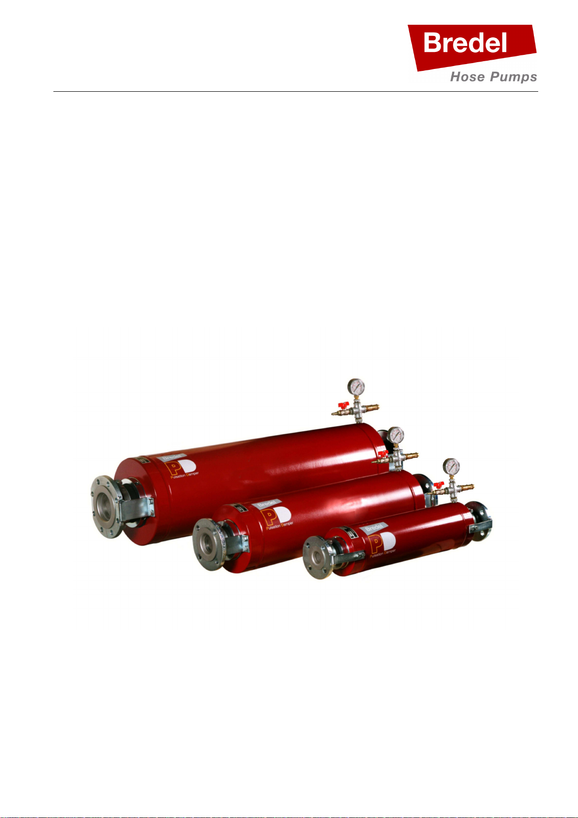
Pulsation damper series
PD/40, PD/65 and PD/100
Manual
ORIGINAL INSTRUCTIONS
Page 2

© 2013 Watson-Marlow Bredel B.V.
All rights reserved.
The information provided herein may not be reproduced and/or published in any form, by print, photo
print, microfilm or any other means whatsoever (electronically or mechanically) without the prior
written authorization of Watson-Marlow Bredel B.V.
The information provided can be changed without prior notification. Watson-Marlow Bredel B.V. or
one of its representatives cannot be held liable for possible damage resulting from use of this manual.
This is an extensive limitation of the liability which applies to all damage, inclusive of (without
limitation) compensating, direct, indirect or consequential damage, loss of data, income or profit, loss
or damage to possessions and claims of third parties.
Watson-Marlow Bredel B.V. provides the information in this manual “as is” and does not take any
responsibility and does not give any guarantee on this manual or its content. Watson-Marlow Bredel
B.V. rejects all responsibilities and guarantees. Furthermore, Watson-Marlow Bredel B.V. does not
take responsibility for and does not guarantee that information in this manual is accurate, complete or
up to date.
Names, trade names, brands, etc. used by Watson-Marlow Bredel B.V. may not, as per the legislation
concerning the protection of trade names, be considered as available.
2
Page 3

CONTENTS
CONTENTS ......................................................................................................................................... 3
1 GENERAL .................................................................................................................................. 4
1.1 How to use this manual ...................................................................................................... 4
1.2 Original instructions ........................................................................................................... 4
1.3 Service and support ........................................................................................................... 4
1.4 Environment and disposal of waste.................................................................................... 4
2 SAFETY ..................................................................................................................................... 5
2.1 Symbols ............................................................................................................................. 5
2.2 Intended use ...................................................................................................................... 5
2.3 Compliance Pressure Equipment Directive ........................................................................ 5
2.4 Use In Potentially Explosive Environments (ATEX) ............................................................ 5
2.5 Responsibility .................................................................................................................... 6
2.6 Qualification of the user ..................................................................................................... 6
2.7 Regulations and instructions .............................................................................................. 6
3 WARRANTY CONDITIONS ........................................................................................................ 7
4 DESCRIPTION ........................................................................................................................... 8
4.1 Identification of the product ................................................................................................ 8
4.2 Operation of the pulsation damper ..................................................................................... 8
4.3 Pulsation damper hose ...................................................................................................... 9
4.4 Pulsation damper selection .............................................................................................. 10
5 INSTALLATION AND COMMISSIONING ................................................................................ 11
5.1 Unpacking ........................................................................................................................ 11
5.2 Inspection ........................................................................................................................ 11
5.3 Installation conditions ...................................................................................................... 11
5.3.1 Ambient conditions ............................................................................................... 11
5.3.2 Set-up .................................................................................................................. 11
5.4 Lifting and moving the pulsation damper .......................................................................... 12
5.5 Setting the pulsation damper pressure level for operation ................................................ 12
6 MAINTENANCE ....................................................................................................................... 14
6.1 Cleaning the pulsation damper hose internally ................................................................. 14
6.2 Removing the pulsation damper hose .............................................................................. 14
6.3 Replacing the pulsation damper hose .............................................................................. 15
6.4 Checking the Pressure relief valve ................................................................................... 16
7 TROUBLESHOOTING ............................................................................................................. 17
8 SPECIFICATIONS .................................................................................................................... 18
8.1 General information ......................................................................................................... 18
8.2 Torque values .................................................................................................................. 18
8.3 Weights ........................................................................................................................... 19
8.4 Dimensions ...................................................................................................................... 19
8.5 Spares list ........................................................................................................................ 20
1.2 Surface treatment ............................................................................................................ 21
9 EC DECLARATION OF CONFORMITY ................................................................................... 22
10 SAFETY FORM ........................................................................................................................ 23
3
Page 4

1 GENERAL
1.1 How to use this manual
This manual is intended as a reference book by means of which qualified users are able to install,
commission, operate and maintain the pulsation dampers mentioned on the front cover.
1.2 Original instructions
The original instructions for this manual have been written in English. Other language versions of this
manual are a translation of the original instructions.
1.3 Service and support
For information with respect to specific adjustments, installation, maintenance or repair jobs which fall
beyond the scope of this manual, contact your Bredel representative. Make sure you have the
following information at hand:
• serial number pulsation damper
• type number pulsation damper
You will find this data on the identification plate of the pulsation damper (see paragraph
4.1 Identification of the product).
1.4 Environment and disposal of waste
Enquire within your local government about the possibilities for reuse or environment friendly
processing of packaging materials, (contaminated) lubricant and oil.
Always observe the local rules and regulations with respect to processing (non-reusable)
parts of the pulsation damper.
4
Page 5
2 SAFETY
WARNING
CAUTION
2.1 Symbols
In this manual the following symbols are used:
Procedures which, if not carried out with the necessary care, may result
in serious damage to the pulsation damper or in serious bodily harm.
Procedures which, if not carried out with the necessary care, may result
in serious damage to the pulsation damper, the surrounding area or the
environment.
Remarks, suggestions and advice.
Procedures, remarks, suggestions or advise which refer to use in
potentially explosive atmospheres (ATEX) in accordance with European
guideline 94/9/EC.
2.2 Intended use
The pulsation damper is exclusively designed for the damping of pulses on the discharge side of a
Bredel hose pump. After consultation with your Bredel representative, and only on certain conditions,
the pulsation damper may be used as a pressure relief valve. Every other or further use is not in
conformance with the intended use1. The manufacturer cannot be held responsible for any damage or
harm resulting from this. The pulsation damper is designed in conformance with the current European
standards and directives. Only use the pulsation damper in conformance with the intended use
described above. If you want to change the application of your pulsation damper, contact your Bredel
representative first.
1
The “intended use” as laid down in EN 292-1 is “…the use for which the technical product is intended in accordance with
the specifications of the manufacturer, inclusive of his indications in the sales brochure”. In case of doubt it is the use
which appears to be its intended use judging from the construction, execution and function of the product. Observing the
instructions in the user’s documentation also belongs to intended use.
2.3 Compliance Pressure Equipment Directive
The pulsation dampers as mentioned on the front cover are in full compliance with the European
Pressure Equipment Directive 97/23/EC.
2.4 Use In Potentially Explosive Environments (ATEX)
The pulsation dampers PD/40, PD/65 and PD/100 can be used in a potentially explosive atmosphere
(ATEX). The pulsation damper is not classed as ATEX equipment since it contains no ignition source
from its own. It is considered as part of the pump and the ATEX code for the pump is applicable,
meaning it can operate under the same ATEX environment as the pump it is attached to. In general
this means the damper is suitable for Group II, category 2 and temperature class T4.
5
Page 6
WARNING
WARNING
When operating under ATEX pay extra attention to the following:
• Pulsation Damper to be installed, operated and maintained according this manual (see chapter
8 SPECIFICATIONS).
• Make sure the damper is connected to the earth. In general this is the case when the damper is
connected to the pump and the piping system. By construction all parts are electrically connected.
This can be checked by measuring the electrical resistance to the earth. The electrical resistance
to any ground connection should be less than 1 MOhm.
In case it is not possible to create an earth/ground connection with less
than 1 MOhm, one should make an additional PE (protective earth)
connection to the pulsation damper. (see chapter 5 INSTALLATION
AND COMMIsSIONING).
2.5 Responsibility
The manufacturer does not accept any responsibility for damage or harm caused by not (strictly)
observing the safety regulations and instructions in this manual or by negligence during installation,
use, maintenance and repair of the pulsation dampers mentioned on the front cover. Depending on
the specific working conditions or accessories used, additional safety instructions can be required.
Immediately contact your Bredel representative, if you notice a potential danger while using your
pulsation damper.
The user of the pulsation damper is always fully responsible for
observing the local valid safety regulations and directives. Observe
these safety regulations and directives when using the pulsation
damper.
2.6 Qualification of the user
The installation, operation and maintenance of the pulsation damper should be carried out by well
trained and qualified users. Temporary staff and persons in training may only use the pulsation
damper under the supervision and responsibility of well trained and qualified users.
2.7 Regulations and instructions
• Everyone who works with the pulsation damper must be aware of the content of this manual and
observe the instructions with great care.
• Never change the order of the actions to be carried out.
• Always store the manual near the pulsation damper.
6
Page 7

3 WARRANTY CONDITIONS
The manufacturer offers a two year warranty on all parts of the pulsation damper. This means that all
parts will be repaired or replaced free of charge with the exception of consumables, such as hoses
and seals, or parts which have been misused or have been intentionally damaged. If parts are used
that are not Watson-Marlow Bredel B.V. (hereafter called Bredel) parts, every warranty becomes void.
Damaged parts which are covered by the applicable warranty conditions can be returned to the
manufacturer. The parts must be accompanied by a fully filled in and signed safety form, as present in
the back of this manual. The safety form must be applied to the outside of the shipping carton. Parts
which have been contaminated or which have been corroded by chemicals or other substances which
can pose a health risk, must be cleaned before they are returned to the manufacturer. Furthermore, it
should be indicated on the safety form which specific cleaning procedure has been followed, and it
should be indicated that the equipment has been decontaminated. The safety form is required at all
items, even if the parts have not been used.
Warranties purporting to be on behalf of Bredel B.V. made by any person, including representatives of
Bredel, its subsidiaries, or its distributors, which do not accord with the terms of this warranty shall not
be binding upon Bredel unless expressly approved in writing by a Director or Manager of Bredel.
7
Page 8

4 DESCRIPTION
4.1 Identification of the product
The pulsation damper and pulsation damper hose can be identified by the contents of the
identification plate on the pulsation damper housing and the hose label.
The identification plate of the pulsation damper contains the following information, relevant for
identification:
A. Type
B. Serial number
C. Identification number of Notified
Body (PD/65 and PD/100 only)
D. Year of manufacture
The hose label on the pulsation damper hose contains following information:
A. Re-order number
B. Internal diameter
C. Type of material of inner liner
D. Maximum permissible working pressure
E. Production code
4.2 Operation of the pulsation damper
The Bredel pulsation damper reduces the pulses created in the discharge line by the hose pump. This
is achieved by means of a thick-walled, reinforced rubber hose which is mounted in a carbon steel,
cylindrical pressure vessel. The hose is surrounded by compressed gas (air or nitrogen).
Pulses are created when a pressing shoe leaves the pump hose, while rotating. Instantly the volume
in the discharge line will increase with the volume of the pressing shoe. This will result in a pressure
drop in the discharge line.
8
Page 9

When the discharge pressure drops, the pulsation damper hose collapses and compensates for the
Hose
Material
Colour
Article number:
PD/40
PD/65
PD/100
AB
C
released volume of the pressing shoe in the discharge line. Hereby the pulse will be reduced.
Dependant on the application the damper can reduce the pulse down to 10%. The damper is most
effective above 500 kPa discharge pressure. The pulsation dampers can be applied up to a operating
pressure of 1600 kPa. The pulsation dampers are safeguarded for over-pressure by a pressure-relief
valve.
4.3 Pulsation damper hose
The pulsation damper hose liner material should be chemically resistant to the product to be pumped.
Dependent on the specific requirements of your application, a matching hose should be selected.
A. Outer extruded layer made of natural rubber
B. Four nylon reinforcement layers
C. Inner extruded liner
For each pulsation damper, various hose types are available. The material of the inner liner of the
hose determines the hose type. Each hose type is marked by a unique colour code.
type
code
NR Natural rubber Purple P040020 P065020 P100020
NBR Nitrile rubber Yellow P040040 P065040 P100040
EPDM EPDM Red P040075 P065075 P100075
Consult your Bredel representative for Hose Pumps for more detailed
information about the chemical and temperature resistance of pulsation
damper hoses.
Store the pulsation damper hose in a cool, dry place and do not subject
it to sunlight.
9
Page 10

Selection table pump and pulsation damper
Pulsation damper
Pump
4.4 Pulsation damper selection
The pulsation damper types mentioned on the front cover are functional with more than one type of
Bredel hose pumps. In the following table the right pulsation damper can be selected to match your
hose pump:
type:
type:
PD/40 Bredel 25, Bredel 32, Bredel 40
PD/65 Bredel 50, Bredel 65
PD/100 Bredel 80, Bredel 100
If you are in doubt about the correct installation of your pulsation
damper, contact your Bredel representative for assistance. They will
advise about the installation layout, pipe diameters, etc, to ensure
optimum performance of your pulsation damper.
10
Page 11

5 INSTALLATION AND COMMISSIONING
5.1 Unpacking
When unpacking carefully follow the instructions as given on the packaging or on the pulsation
damper.
5.2 Inspection
Check that your delivery is correct and check it for any transport damage (see also paragraph
4.1 Identification of the product).
5.3 Installation conditions
5.3.1 Ambient conditions
Make sure the ambient temperature, during normal operation of the pulsation damper, does not fall to
below -20°C, and does not exceed +45°C.
5.3.2 Set-up
When installing the pulsation damper consider the following points:
• The pulsation damper will not be effective for variable pump speeds or variable discharge
pressures.
• Limit the presence of sharp bends. Make sure that the radius of the bent discharge line is as large
as possible. It is recommended to use Y-connections instead of T-connections.
• The pulsation damper will be most effective if it is directly mounted onto the hose pump. Minimise
the distance between pump and pulsation damper.
• The pulsation damper may be installed in either the horizontal or vertical position.
• The pulsation damper must be suitably supported.
• The pulsation damper must be electrically connected to earth. (Resistance less than 1 MOhm). If
required make a PE connection to the pulsation damper. The PE wire can be connected to one of
the bolts attaching the flange bracket to the damper housing.
If installed in a potentially explosive atmospheres, properly earth the
pulsation damper and respect the instructions as mentioned in
paragraph 2.4 Use In Potentially Explosive Environments (ATEX)
• Avoid, at all times, a pressure higher than the maximum operating pressure.
• When using a Bredel series 265-2100 pump with pulsations over 500 kPa (5 bar, 72.5 psi) use
two pulsation dampers - one for each pump head.
11
Page 12

WARNING
CAUTION
• Avoid too heavy loads on the flanges. The maximum forces are given in the table below:
Maximum flange loads
Force Unit PD/40 PD/65 PD/100
F1 N 1000 1400 2000
lbf 225 315 450
F2 N 500 700 1000
lbf 112 157 225
F3 N 200 300 400
lbf 45 67 90
5.4 Lifting and moving the pulsation damper
To lift, move and position the pulsation damper, suitable hoisting belts must be used. The best place
to attach the hoisting belts is immediately behind both flanges of the pulsation damper. Keep in mind
the pulsation damper’s weight. For weights see also paragraph 8.3 Weights.
If the pulsation damper is to be lifted, ensure that all safety regulations
for lifting movements are adhered to and that the lifting is carried out by
qualified personnel only.
5.5 Setting the pulsation damper pressure level for operation
The pulsation damper air or nitrogen pressure level must be set. This setting for maximum pulse
reduction depends on the process condition. Therefore the setting can only be obtained when the
pump is running at operating conditions.
It is advised to check the pressure relief valve functioning with each installation, hose replacement or
annually (which comes first). (See paragraph 6.4 Checking the Pressure relief valve.)
12
Consider the maximum allowable pressure. The maximum allowable
pressure can either be determined by the pulsation damper, pump or
process. Exceeding the maximum allowable pressure may lead to
serious injuries or damage to the pump and the environment.
Page 13

CAUTION
Consider the filling medium for the pulsation damper housing – in this
CAUTION
case compressed air or nitrogen. If in doubt concerning the correct
filling medium for your pulsation damper, contact your Bredel
representative for assistance.
Before pressurizing the pulsation damper ensure that the pulsation
damper is built in the piping system, ensure that the suction and
discharge valves are open, ensure that any drain valves are closed.
(process released for operation)
1. Shut the ball valve (pos. 17) on the pulsation
damper.
2. Connect the filling medium to the filling nipple (pos.
18).
3. Apply pressure to the pulsation damper by the filling
medium. Minimum filling medium supply pressure
should at least be equal to the process working
pressure directly upstream of the pulsation damper.
4. Start the pump
5. Open the ball valve (pos. 17) gently. Filling medium will now enter and pressurize the vessel.
Check the pressure gauge (pos. 20) for the actual pressure inside the vessel.
6. Pressurize the vessel to approximately 80% - 90% of the actual process working pressure of the
hose pump, directly upstream of the pulsation damper.
7. When the required pressure is reached, shut off the ball valve (pos. 17).
8. Shut off the supply pressure of the filling medium
Pressurize the vessel to approximately 80%-90% of the actual process
working pressure directly upstream of the pulsation damper as a
guideline. The actual vessel pressure depends on many variables,
making the optimum setting process specific. It is advised to slowly
increase the vessel pressure until the pressure fluctuations upstream of
the pulsation damper are minimized and optimal damping is obtained.
If the actual process working pressure is very low (for example during
standstill or after a transfer cycle is completed) it is advised to relief the
pressure from the pulsation damper.
13
Page 14

WARNING
WARNING
CAUTION
WARNING
6 MAINTENANCE
Careful maintenance and, in particular, scrupulous cleaning are essential for problem-free operation
of the pulsation damper.
• Before carrying out any maintenance to the pulsation damper, please thoroughly acquaint yourself
with the directives in the chapter 2 SAFETY.
• Any repair to the pulsation damper is to be carried out by properly skilled and authorised users
only.
• After cleaning and maintenance work, do not use the pulsation damper until all parts that have
been removed, are reinstalled correctly.
Release the pressure from the pulsation damper by means of the ball
valve near the pressure-relief valve, before starting on any work to the
pulsation damper.
Protect your hands and face from any dangerous substances when
handling or examining the pulsation damper hose.
After maintenance has been carried out, and before switching the pump
back on, ensure that all valves present in the pipe work are opened.
6.1 Cleaning the pulsation damper hose internally
The inside of the pulsation damper hose is easily cleaned by flushing the pump and pulsation damper
with clean water. If a cleaning fluid is added to the water, it must be checked that the hose liner
material is resistant to that.
With many products to be pumped, it is necessary to clean the pulsation
damper hose immediately once the pump is stopped, to avoid
solidification and hardening of the product within the hose.
6.2 Removing the pulsation damper hose
1. Disconnect the electrical supply from the corresponding pump and close any valves to minimise
product loss.
2. Position a tray under the pulsation damper. This tray must be sufficiently large to collect all liquid
3. Release all pressure from the pulsation damper using the ball valve (pos. 17).
4. Support the pulsation damper in such a way that it cannot fall during disassembly.
14
product inside the pulsation damper.
If the pulsation damper hose is cracked or worn, liquid product to be
pumped may escape via the ball valve (pos. 17). Therefore, take the
necessary safety precautions.
Page 15

5. Remove the mounting bolts from both flanges. Lift the pulsation damper onto a suitable
CAUTION
workbench. Adhere to the instructions for lifting and moving as mentioned in paragraph 5.4 Lifting
and moving the pulsation damper.
6. Loosen the hose clamps (pos. 8) from both ends.
7. Unscrew the bolts (pos. 11 and 12) from both flanges (pos. 9).
8. Unscrew the locknut (pos. 7) on both sides until the compression on the pulsation damper hose
has relieved.
9. Remove both inserts (pos. 10) from the pulsation damper hose.
10. Remove both metal rings (pos. 5 + 6), O-rings (pos. 4) and neck-rings (pos. 3)
11. Remove the mounting bolts from both flange supports (pos. 9) together with the inserts (pos. 10).
12. Remove the pulsation damper hose from the housing.
6.3 Replacing the pulsation damper hose
After the pulsation damper hose has been removed, as described in “Removing the pulsation damper
hose”, the (new) hose can be installed in the pulsation damper.
If you are installing a new pulsation damper hose, and you wish to
continue pumping the same product, ensure that the colour code of the
new hose matches the colour code of the old, used hose.
1. Check all parts to be installed for any damage and replace when necessary.
2. Grease all metal parts which are not corrosion-protected and O-rings with Molykote® 55M or
equivalent.
3.
Place one of the collar bushes (pos. 3) in the damper housing. Install the pulsation damper hose
(pos. 2). Place the second collar bush (pos. 3).
4.
Slide both O-rings (pos. 4) at both ends over the pulsation damper hose.
5.
Place both metal rings (pos. 5 + 6) and hand-tighten both pressing rings (pos. 7).
6.
Loosely place the hose clamps (pos. 8) at both ends.
7.
Loosely place the flanges on both sides (pos. 9) and place the inserts. (pos. 10)
8.
Tighten the pressing rings (pos. 7) (see also paragraph 8.2 Torque values).
9.
Tighten both flanges (pos. 9) using the corresponding bolts and spring washers. (pos. 11 and 12)
10.
Lift the pulsation damper from the work bench and place it back into the pipe work. Observe the
instructions for lifting and moving as mentioned in paragraph 5.4 Lifting and moving the pulsation
damper. Mount and tighten the mounting bolts to the flanges at both ends.
11. Shut the ball valve (pos. 17) on the pulsation damper.
12. Connect the filling medium to the filling nipple.
13. Apply pressure to the pulsation damper by the filling
medium.
14. Open the ball valve (pos. 17) gently. Filling medium
will now enter and pressurize the vessel. Check the
pressure gauge (pos. 20) for the actual pressure
inside the vessel.
15
Page 16

CAUTION
CAUTION
15. Pressurize the vessel to 1400 kPa (14 bar, 203 psi) above atmospheric. By pressurizing the hose
will be stretched outwards, forcing the hose ends over the inserts.
16. Close the ball valve.
17.
Tighten both hose clamps (pos. 8) with the proper torque values.
The minimum required torque values as advised (see paragraph 8.2 Torque values) can
not always be realized in the field. This is due to the unknown friction between tightening
bolt and clamp. Especially in case of used stainless steel clamps that are not properly
greased. In such case the applied bolting torque does not reflect the required clamping
force of the hose clamp.
So in case the minimum specified torque values are not sufficient it is advised to increase
the bolt torque until a sealed situation is obtained. Here the absolute torque value is of less
importance (although maximum applied bolting torques should remain within the range
specified (see paragraph 8.2 Torque values). It is advised to tighten the clamp until the
outside diameter of the clamp is between 0 to 2 mm (0 to 0.08 inch) below the outside
diameter of the PD hose in unclamped condition.
PD/40 PD/65 PD/100
Advised Clamp OD [mm] 69 – 71 98 – 100 138 – 140
[inch] 2.72 – 2.80 3.86 – 3.94 5.43 – 5.51
The complete PD hose replacement procedure can also be done with the PD outside the
piping system, provided that the inserts are locked by installing an additional flange on both
sides of the pulsation damper flanges and external gas pressure (up to 1700 kPa, 17 bar,
247 psi above atmospheric) can be applied.
6.4 Checking the Pressure relief valve
It is advised to check the pressure relief valve functioning with each installation, hose replacement or
annually (which comes first).
1. Check all parts to be installed for any damage and replace when necessary.
2. Make sure the pulsation damper is fully assembled and installed in the process piping. (If testing is
done with a stand alone pulsation damper the inserts should be blocked by fitting additional
flanges on both flanges of the pulsation damper.)
3. Apply pressure to the pulsation damper by carefully opening the ball valve. The procedure for
applying the pressure is described in the paragraph “Setting the pulsation damper pressure level
for operation”.
4. Around 1700 kPa (17 bar, 247 psi), the pressure relief valve should open, keeping the pressure
from rising further. The proofs the relief valve is fit for duty.
Do not pressurize the pulsation damper if the inserts are not secured. Securing the
insert can be done by installing an additional flange on both flanges of the pulsation
damper or by installing the pulsation damper into the pipe system.
If you want to check the function of the pressure-relief valve, apply pressure to the
vessel just over the maximum allowable working pressure of 1600 kPa (16 bar, 232 psi).
The valve should automatically open. If not, do not apply more than 2300 kPa (23 bar,
334 psi) to the vessel, relieve the pressure and replace the pressure-relief valve if it
does not open before reaching 1900 kPa (19 bar, 276 psi) pressure
16
Page 17

7 TROUBLESHOOTING
Problem
Possible cause
Solution
If the pulsation damper does not function (correctly), consult the following checklist to see if you can
remedy the problem yourself. If you cannot, please contact your Bredel representative.
(Heavy) vibration of
Pump, Pulsation
damper or pipework
Product leakage Not all parts have been
Pressure loss at
pulsation damper
housing
Pressing ring (pos. 7)
Short pulsation
damper hose life
High discharge
Pressure inside vessel
too low
Pressure inside vessel
too high
greased properly.
Damaged O-ring (pos.
4 or 5)
incorrectly mounted
Chemical corrosion of
the hose
pressures
Pressurize the vessel of pulsation
damper again according
5.5 Setting the pulsation damper pressure
level for operation.
Grease all necessary parts. See also
paragraph 6.3 Replacing the pulsation
damper hose.
Replace the O-ring concerned.
Tighten to the specified torque settings
(see paragraph 8.2 Torque values)
Check the compatibility of the hose
material with the product to be pumped.
Consult your Bredel representative for
correct hose selection.
Maximum operating pressure is 1600 kPa.
Check whether the discharge line is
blocked. Make sure the shut-off valves are
fully opened and the pressure-relief valve
(if present) in the discharge line is
functioning properly.
paragraph
High product
temperature
High pulsations Restructure the discharge and inlet
Consult your Bredel representative for
correct pulsation damper hose selection.
conditions.
17
Page 18

8 SPECIFICATIONS
8.1 General information
Description Value
Maximum allowable pressure in vessel 2300 kPa 334 psi
Maximum allowable working pressure
discharge line before pulsation damper
Allowable ambient temperature
Allowable product temperature −10 to +80 °C +14 to +176 °F
Allowable storage temperature
Maximum surface temperature +90 °C (T5) +194 °F (T5)
Air volume vessel See: identification plate
8.2 Torque values
Component Description Unit PD/40 PD/65 PD/100
Pressing ring (pos. 7)
Torque value N/A N/A N/A
Toolbar diameter mm Ø16 Ø16 Ø16
inch Ø0.63 Ø0.63 Ø0.63
Hose clamp (pos. 8)
Torque value 1) Nm 12 - 25 15 - 35 15 - 35
Thread M115 x 2 M145 x 2 M185 x 3
Thread M8 M8 M10
1600 kPa 232 psi
−20 to +45 °C
−40 to +70 °C
−4 to +113 °F
−40 to +158 °F
lbf in 106 - 220 133 - 310 133 - 310
Key width mm 13 13 17
inch 0.51 0.51 0.67
Connecting flange (pos. 11)
Torque value Nm 25 50 85
lbf in 220 440 750
Key width mm 13 17 19
1) Minimum torque value based on new clamps with smooth thread.
See also chapter 6.3 Replacing the pulsation damper hose point 17 for extra instruction on hose
clamp installation.
18
Thread M8 M10 M12
inch 0.51 0.67 0.75
Page 19

8.3 Weights
Damper
Pump
A B C D E F G K1 K2 n L M N
Non
-
Damper
Pump
A B C D E F G K1 K2 n L M N
Non
-
Description Unit PD/40 PD/65 PD/100
Pulsation damper, complete kg 32 75 135
lbs 70.5 165 297
Hose kg 2.2 4.9 11
lbs 4.9 10.8 24.2
8.4 Dimensions
Dimensions in [mm]
Type
PD/40
PD/65
PD/100
Type
Bredel 25
Bredel 32
Bredel 40
Bredel 50
Bredel 65
Bredel 80
Bredel 100
40 168 800 735 16 -
65 245 1050 975 16
100 324 1356 1295 18 8
Dimensions in [inch]
Type
PD/40
PD/65
PD/100
Type
Bredel 25
Bredel 32
Bredel 40
Bredel 50
Bredel 65
Bredel 80
Bredel 100
1.57 6.61 31.50 28.94 0.63 -
2.56 9.65 41.34 38.39 0.63
3.94 12.76 53.39 50.98 0.71 0.31
Steel SS
- 6
6 3 65 - 145 185
Steel SS
0.16
0.16 - 1.26
0.10 1.57 - 4.33 5.91
- 0.24
0.24 0.12 2.56 - 5.71 7.28
0.31
0.12 3.94 - 7.09 8.66
ferro
4
20 175
4 - 32 100 140
2.5 40 - 110 150
20 175
8
48 175
3 100 - 180 220
ferro
0.79 6.89
0.79 6.89
1.89 6.89
- 25
- 50
- 80
- 0.98
- 1.97
- 3.15
85 115 14
4
125 165
4
160 200
8
3.35 4.53 0.55
0.16
3.94 5.51
4.92 6.50
0.16
6.30 7.87
0.31
18
18
18
0.71
0.71
0.71
19
Page 20

8.5 Spares list
Pos. Qty. Description PD/40 PD/65 PD/100
1 1 Housing P040202 P065202 P100202
1 Hose NR P040020 P065020 P100020
2
3 2 Collar bush P040204 P065204 P100204
4 2 O-ring NBR S110701 S111001 S111351
5 2 O-ring NBR S123451 S123541 S123641
6 2 Metal ring P040206NS P065206NS P100206NS
7 2 Pressing ring P040207 P065207 P100207
8 2 Hose clamp C122007 C122014 C101054
9
10
1 Hose NBR P040040 P065040 P100040
1 Hose EPDM P040075 P065075 P100075
2 Flange, steel, EN 40-25 P040213
2 Flange, steel, EN 40-32 P040293
2 Flange, steel, EN 40-40 P040209
2 Flange, steel, EN 65-50 P065213
2 Flange, steel, EN 65-65 P065209
2 Flange, steel, EN 80-100 P100213
2 Flange, steel, EN100-100 P100209
2 Flange, steel, ASA 40-25 P040271
2 Flange, steel, ASA 40-32 P040272
2 Flange, steel, ASA 40-40 P040273
2 Flange, steel, ASA 65-50 P065271
2 Flange, steel, ASA 65-65 P065273
2 Flange, steel, ASA 80-100 P100271
2 Flange, steel, ASA100-100 P100273
2 Flange, steel, JIS 40-25 P040277
2 Flange, steel, JIS 40-32 P040278
2 Flange, steel, JIS 40-40 P040279
2 Flange, steel, JIS 65-50 P065277
2 Flange, steel, JIS 65-65 P065279
2 Flange, steel, JIS 80-100 P100277
2 Flange, steel, JIS100-100 P100279
2 Insert, SS PD40-25 P040215
2 Insert, PVC PD40-25 P040216
20
Page 21

Pos. Qty. Description PD/40 PD/65 PD/100
2 Insert, PP PD40-25 P040290
2 Insert, PVDF 40-25 P040280
2 Insert, SS PD 40-32 P040295
2 Insert, PVC PD 40-32 P040296
2 Insert, PP PD 40-32 P040291
2 Insert, PVDF 40-32 P040281
2 Insert, SS PD 40-40 P040211
2 Insert, PVC PD 40-40 P040212
2 Insert, PP PD40-40 P040292
2 Insert, PVDF PD40-40 P040282
2 Insert, SS PD 65-50 P065215
2 Insert, PVC PD 65-50 P065216
2 Insert, PP PD 65-50 P065290
2 Insert, PVDF 65-50 P065280
2 Insert, Steel PD 65-65 P065210
2 Insert, SS PD 65-65 P065211
2 Insert, PVC PD 65-65 P065212
2 Insert, PP PD 65-65 P065292
2 Insert, PVDF 65-65 P065282
2 Insert, Steel PD 100-80 P100214
2 Insert, SS PD 100-80 P100215
2 Insert, PVC PD 100-80 P100216
2 Insert, PP PD 100-80 P100290
2 Insert, PVDF 100-80 P100280
2 Insert, Steel PD 100-100 P100210
2 Insert, SS PD 100-100 P100211
2 Insert, PVC PD 100-100 P100212
2 Insert, PP PD 100-100 P100292
2 Insert, PVDF 100-100 P100282
8 Bolt M8 x 20 F111071
11
12
13 1 Nipple A132511 A121004 A121004
14 1 Cross piece G1/2” A123003 A123003 A123003
15 1 Reducing ring G1/2”x 3/8” A122006 A122006 A122006
16 1 Reducing ring G1/2”x 1/4” A122005 A122005 A122005
17 1 Ball valve G3/8” A106002 A106002 A106002
18 1 Nipple G3/8” A125005 A125005 A125005
19 1 Safety valve G1/2” A210003 A210003 A210003
20 1 Pressure gauge 0-25 bar A220001 A220001 A220001
21 1 Stop A124514 A124516 A124516
8 Bolt M10 x 25 F111096
8 Bolt M12 x 30 F111130
8 Washer M8, Spring Lock F336011
8 Washer M10, Spring Lock F336012
8 Washer M12, Spring Lock F336013
1.2 Surface treatment
• After surface preparation, one layer of two-component acrylate is used for surface protection.
Standard color is RAL 3011, however other colors are optional. Contact your Bredel
representative for details on surface treatment.
• All galvanized parts, excluding fasteners, will have an electrolytic zinc layer of 15-20 microns.
21
Page 22

Type
Module(s)
Cat.
9 EC DECLARATION OF CONFORMITY
We,
Watson Marlow Bredel B.V.
Sluisstraat 7
P.O. Box 47
7490 AA Delden
The Netherlands
herewith declare, on our own responsibility, that the following partly completed machinery
to which this declaration applies, fully or partly complies with the essential requirements of:
• the European machine directive 2006/42/EC, annex II.1.B, EN60204-1 and
• the European pressure equipment directive 97/23/EC (PED).
Pulsation damper for hose pumps,
PD/40, PD/65 and PD/100
The products as mentioned above comply to fluid classification group I (dangerous fluids) and were
subjected to the conformity assessment procedure as mentioned in the table below. EC-type
examination (module B) has been in conformity with AD 2000 Edition 2002.
PD/40 A1
PD/65 B + C1
PD/100 B + C1
The monitoring of the products is performed by Lloyds Register Netherlands B.V., located in
Rotterdam, the Netherlands. Lloyd’s Register Netherlands is a registered body notified under
directive 97/23/EC Pressure Equipment under identification number: 0038.
When this pulsation damper is to be installed into a machine or is to be assembled with other
machines for installations, it is not be put into service until the relevant machinery has been declared
in conformity with these guidelines.
J. van den Heuvel,
Managing Director,
The Netherlands, Delden
1 August 2013
I
II
III
22
Page 23

10 SAFETY FORM
Product Use and Decontamination Declaration
In compliance with Health & Safety Regulations the user is required to declare the substances which have been in contact
with the product(s) you are returning to Watson-Marlow Bredel B.V. or any of its subsidiaries or distributors. Failure to do so
will cause delays in servicing the item or in issuing a response. Therefore, please complete this form to ensure that we have
the information before receipt of the item(s) being returned. A further copy must be attached to the outside of the packaging
containing the item(s). The user is responsible for cleaning and decontaminating the item(s) before returning them. Please
complete a separate Decontamination Certificate for each item returned. RGA/KBR No: …………………...
1. Company: …………………………………………………………………………….……………………….……..
Address: ……………..…………………………………………………………………………………..…………
Zip Code: ...……………………………….……
Town: …….…………………………………
Country: ………….……………………………
2. Product: …………………………………….…
2.1 Serial Number:…………………………………….
2.2 Has the Product been used?
Yes (Go to section 3)
Telephone: ………………..…………………………………
Fax: ..………………………………………………...
3.4 Cleaning fluid to be used if residue of chemical is found
during service:
(a) ……………………………………………….…
(b) ……………………………………………….…
(c) …………………………………………….……
(d) …………………………………….……….…
No (Go to section 4)
3. Details of the substances pumped
3.1 Chemicals names:
(a) ………………………………..……..……….
(b) ……………………………….……………….
(c) …………………………………….…....……
(d) ..…………………………………...………….
3.2 Precautions before handling these substances:
(a) ………………………………………………..
(b) …………………………………………….….
(c) ………………………………………………..
(d) ………………………………………………..
3.3 Actions to be taken in event of human contact:
(a) ………………………………………………..
(b) …………………………………………….….
(c) ………………………………………………..
(d) ………………………………………………..
4. I hereby confirm that the only substance(s) that the
equipment specified has pumped or come into contact
with those named, that the information given is correct
and the carrier has been informed if the consignment is
of a hazardous nature
5. Signed: ……………………………..……………
Name: …………………..……...……………….
Position: ………………………………..…………
Date: ……………………………….………….
Note: To assist us in our service, please describe any
fault condition you have witnessed.
……………………………………………………………
……………………………………………………………
……………………………………………………………
……………………………………………………………
……………………………………………………………
23
Page 24

America:
Watson-Marlow Pumps Group
37 Upton Technology Park
Wilmington, MA 01887
USA
Telephone: 800 - 282 - 8823
978 - 658 - 6168
Fax: 978 - 658 - 0041
Internet: www.wmpg.com
E-mail: support@wmpg.us
Other areas:
Watson-Marlow Bredel B.V.
P.O. Box 47
NL-7490 AA Delden
The Netherlands
Phone: +31 74 3770000
Fax: +31 74 3761175
E-mail: bredel@wmpg.com
Internet: www.bredel.com
TS03-060-E
29210391
© 2013 Watson-Marlow Bredel B.V.
Member of the Spirax-Sarco Engineering Group
24
 Loading...