

Page 1
INSTRUCTION HANDBOOK
PD12IHS / PD12IDH
PD12 IHS / PD12 IDH
(example; exact model may vary)
This instruction handbook is for the daily users of the equipment.
PD12IHS_PD12IDH IH EN 74-115-181 v2.00.doc Version: 2.00 Page 1 of 19
Page 2

INSTRUCTION HANDBOOK
PD12IHS / PD12IDH
Table of Contents
1
Introduction .............................................................................................................................. 3
1.1 The peristaltic principle ............................................................................................................ 3
1.2 Abbreviations in this manual .................................................................................................... 3
1.3 Symbols on the machine ......................................................................................................... 4
1.4 Caution and employee safety .................................................................................................. 4
1.5 Essential training before daily use ........................................................................................... 4
1.6 References .............................................................................................................................. 5
2 General information ................................................................................................................. 5
2.1 Unpacking and inspection ........................................................................................................ 5
2.2 Technical specifications ........................................................................................................... 5
3 Installation ............................................................................................................................... 6
4 Daily Use ................................................................................................................................. 8
4.1 Starting-up and running ........................................................................................................... 8
4.2 Placing the product container .................................................................................................. 8
4.3 Choosing tubes, y-connectors and filling nozzles ..................................................................... 9
4.4 Assembly of tubes and Y-connectors ..................................................................................... 10
4.5 Mounting of silicone tubes ..................................................................................................... 11
4.6 Dispensing ............................................................................................................................. 12
4.6.1 Prime tubes ........................................................................................................................... 12
4.6.2 Problems with drips ............................................................................................................... 12
4.6.3 Problems with hard feed ........................................................................................................ 12
5 Choice of parameters ............................................................................................................ 13
5.1 Programming principle ........................................................................................................... 13
5.1.1 Description of PD12 specific functions/parameters ................................................................ 13
Function 1 – Volume .......................................................................................................................... 13
Function 2 - Tube diameter ................................................................................................................ 13
Function 3 - Velocity .......................................................................................................................... 13
Function 4 - Acceleration/deceleration ............................................................................................... 14
Function 5 - Reversing (back suction) ................................................................................................ 14
6 Cleaning ................................................................................................................................ 15
6.1 Cleaning Frequency .............................................................................................................. 15
6.2 Preparations for cleaning ....................................................................................................... 15
6.3 Cleaning Guidance ................................................................................................................ 15
6.4 Detergents or cleaning agents ............................................................................................... 15
7 Maintenance & service .......................................................................................................... 16
7.1 Daily maintenance ................................................................................................................. 16
7.2 Service .................................................................................................................................. 16
7.3 Methods and frequency of inspections for safety functions .................................................... 16
8 Interface and change of voltage ............................................................................................. 17
8.1 PD12 interface ....................................................................................................................... 17
8.2 Connecting multiple PD12’s to flexnet ................................................................................... 18
8.3 Change of voltage ................................................................................................................. 18
9 Declaration of conformity ....................................................................................................... 19
PD12IHS_PD12IDH IH EN 74-115-181 v2.00.doc Version: 2.00 Page 2 of 19
Page 3

INSTRUCTION HANDBOOK
e.g.
As example
Fig.
Figure
Hz
Hertz
i.d.
Internal diameter
IDH
Industrial Double Head
IHS
Industrial High Speed
MC12
Flexicon Master Controller
mA
milli Ampere
msec
milli secunds
o.d.
Outer diameter
PD12
Peristaltic Dispenser
VAC
Volt Alternating Current
VDC
Volts Direct Current
PD12IHS / PD12IDH
1 Introduction
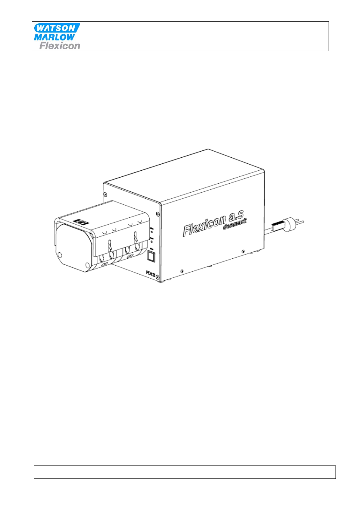
This manual covers two models.
PD12 IHS (high speed). This model fills one bottle at a time.
In the double head the tubes are mounted in pairs of 2 and via y-connectors these are joined into one
tube in order to fill one bottle at a time.
and
PD12 IDH (double head). This model fills two bottles simoultaneously.
In the double head the tubes are mounted in pairs of 2 and via y-connectors each set of tubes are
joined into one tube in order to fill two bottles simoultaneously.
In general all sections of the manual cover both models; unless clearly specified.
1.1 The peristaltic principle
PD12 operates with a peristaltic dispenser head (tube pump), where the liquid only comes into
contact with the flexible tube, the tube connections and the filling nozzle. The tubes are usually made
of silicone, but other materials can also be used.
The dispenser head is designed in such a way that sterilized tubes can be mounted in the head
without affecting the sterility.
The dispenser head is self-priming, and the dispenser head itself can stand to be run dry (not
recommended for the sake of the tubes).
The dispenser head on PD12 works with four parallell tubes which are squeezed by rollers mounted
on ball bearings. The rollers in are offset in order to eliminate pulsation.
1.2 Abbreviations in this manual
PD12IHS_PD12IDH IH EN 74-115-181 v2.00.doc Version: 2.00 Page 3 of 19
Page 4

INSTRUCTION HANDBOOK
PD12IHS / PD12IDH
1.3 Symbols on the machine
Warning against touching Warning against high voltage
Fig. 1 – Symbols
1.4 Caution and employee safety
This manual should be read before using the PD12.
It is strongly advised that
- Any kind of maintenance or cleaning of the machine not is carried out while power is
connected
- Unauthorised / non-trained personnel should not open the cover of the electrical parts
- The machine is placed in such a way that it is not exposed to high humidity, high temperatures
or other abnormal operating environment.
- The machine is not to be used in explosion hazardous environments.
- When operating the machine make sure that the dispenser heads are closed and that safety
cover is placed above.
- The machine should be used for dosing and filling of liquid fluids, only.
A peristaltic dispenser head is not suitable for viscous products; see section 4.3
1.5 Essential training before daily use
Read the section with Daily Use, thoroughly before using the machine.
Protective equipment and protective devices are installed:
The machine is equipped with a safety cover which protects the operator from hazards; the
machine will not run unless the safety cover is placed.
Always respect the symbols on the machine.
Cleaning must be performed as described in section 6.
PD12IHS_PD12IDH IH EN 74-115-181 v2.00.doc Version: 2.00 Page 4 of 19
Page 5
INSTRUCTION HANDBOOK
Buttons:
PD12IHS / PD12IDH
1.6 References
- MC12 manual
2 General information
2.1 Unpacking and inspection
Please check that all ordered items have been received and that no items are damaged during
transport. In case of any defects or omissions, please contact W-M Flexicon or your supplier
immediately.
2.2 Technical specifications
Dimensions:
Length: 525 mm
Width: 200 mm
Height: 208 mm (incl. Feet)
Fig. 2 – Dimensions
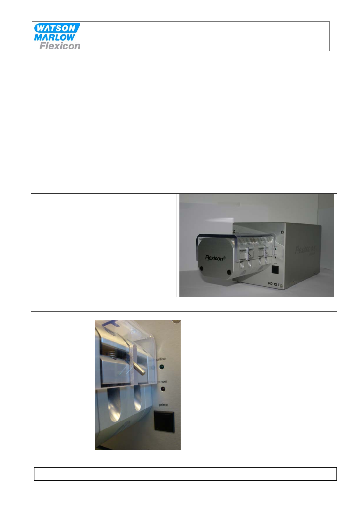
online
Lights when communicating with MC12.
power
Lights when the machine is on.
prime
Pushbutton for tube priming
Fig. 3 - Buttons on PD12
PD12IHS_PD12IDH IH EN 74-115-181 v2.00.doc Version: 2.00 Page 5 of 19
Page 6
INSTRUCTION HANDBOOK
PD12IHS / PD12IDH
Other:
Weight: 13 kg
Motor: High Torque Step Motor MST341B02
PD12 Power consumption: max 150 Watt
Mains: 110/230 VAC earthed, 50/60 Hz
3 Installation
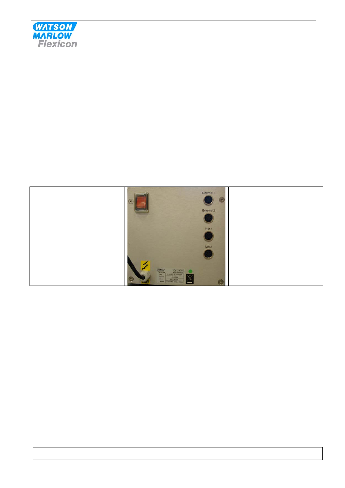
PD12 must be placed on a stable bedplate. All electrical connections are on its rear.
2
3
1
Fig. 4 - Connections
The cable with plug (1) is connected to an earthed switch.
The communication cable from MC12 (type 3) comes fitted with two 4-pin DIN plugs. One is
connected to the "net 1" socket (2) on the PD12, and the other plug is connected to the "net" socket
on MC12.
The terminator supplied with MC12 (4-pin blind DIN plug) is connected to the "net 2" (3) socket on
PD12.
Should the system be operating more than one PD12, the "net 2" socket (3) is to be connected to the
"net 1" socket (2) on the next PD12 by a communication cable (type 3). The terminator is connected
to the last PD12 on the line.
PD12 is now ready to be switched on and to be programmed from the MC12.
If the PD12 is one of several filling stations in a system, none of the stations may have the same
address and it must therefore be changed.
PD12IHS_PD12IDH IH EN 74-115-181 v2.00.doc Version: 2.00 Page 6 of 19
Page 7

Address
1 2 3 4 5 6 7 8 9
10
11
12
13
14
15
16
SW1
1 0 1 0 1 0 1 0 1 0 1 0 1 0 1
0
SW2
1 1 0 0 1 1 0 0 1 1 0 0 1 1 0
0
SW3
1 1 1 1 0 0 0 0 1 1 1 1 0 0 0
0
SW4
1 1 1 1 1 1 1 1 0 0 0 0 0 0 0
0
Change of address is performed via a dip-switch
placed underneath the PD12. This change may
only be carried out when the machine is turned
off at the main isolator.
Addresses between 1 and 16 may be chosen,
and the table below shows the various
combinations.
Address "1" is the factory setting of PD12.
This can be changed – see below.
Dip-switch settings:
INSTRUCTION HANDBOOK
PD12IHS / PD12IDH
PD12IHS_PD12IDH IH EN 74-115-181 v2.00.doc Version: 2.00 Page 7 of 19
Page 8

INSTRUCTION HANDBOOK
Flexicon
Pump Head
Preferred Placement
of container
Normal Placement
of container
Suction side Pressure side
Dispenser head
PD12IHS / PD12IDH
4 Daily Use
4.1 Starting-up and running
Installation section must be carried out before this chapter can be performed.
4.2 Placing the product container
In order to build up adequate pressure, it is recommendable to place the product container at the
same level as dispenser head or preferably above the dispenser head level. Placing the container
higher than dispenser head level provides positive product support and may reduce the calibration
interval. It is also recommended to place the container as close as possible to the dispenser on
suction side.
Fig. 5 - placing the product container
PD12IHS_PD12IDH IH EN 74-115-181 v2.00.doc Version: 2.00 Page 8 of 19
Page 9

INSTRUCTION HANDBOOK
Connector
< 1.00
0,6
0,5
2,4
1.00 – 2.00
1,0
0,8
2,4
2.00 – 3.40
1,6
1,2
3,6
3.40 –14.0
3,2
1,6
3,6
14.0–24.0
4,5
3,2
5,9
24.0 – 44.0
6,0
4,8
7,2
44.0 – 70.0
8,0
6,0
9,5
>70.0 ml
8,0*
8,0
12,4
Connector
< 0.50
0,6
0,5
2,4
0.50 – 1.00
1,0
0,8
2,4
1.00 – 1.70
1,6
1,2
3,6
1.70 – 7.00
3,2
1,6
3,6
7.00 – 12.0
4,5
3,2
5,9
12.0 – 22.0
6,0
4,8
7,2
22.0 – 35.0
8,0
6,0
9,5
>35.0 ml
8,0*
8,0
12,4
* use non-return valve
PD12IHS / PD12IDH
4.3 Choosing tubes, y-connectors and filling nozzles
The filling is carried out by the PD12 which is controlled by the MC12.
The capacity is based on the volume to be dispensed, however a lot of factors can influence on the
obtainable capacity; e.g. choice of tubes and type of product.
These aspects must be considered before choosing the filling settings.
Tubes must be selected according to the application and volume to be filled. Use the table shown
below for choice of tubes according to minimum volume to be filled.
PD12 can operate with different tube dimensions chosen according to the volume to be dispensed.
The tubes are designated by their internal diameters (i.d.) in millimetres. This value is always used as
designation for the individual tube, and this is also the value to be entered in function 2 at the MC12
master controller.
In order to obtain stable and good results, the choice of tubing can be made according to the following
guidelines:
PD12 IHS
Volume
ml
* use non-return valve
Nozzle
mm i.d.
Tubing
mm i.d.
Y-
o.d.
PD12 IDH
Volume
ml
Nozzle
mm i.d.
Tubing
mm i.d.
Y-
o.d.
PD12IHS_PD12IDH IH EN 74-115-181 v2.00.doc Version: 2.00 Page 9 of 19
Page 10

INSTRUCTION HANDBOOK
this.
PD12IHS / PD12IDH
The filling time for a volume of 10.0 ml with a Ø3.2 ID tube is 0.8 seconds with dispenser running in
high speed i.e. 400 in rpm and 100 in acceleration.
The same volume can be obtained with Ø4.8 ID tube in 0.55 seconds for the same parameters.
The contrast here is outweighed by the fact that Ø3.2 ID tube will in this case yields better accuracy
than the option of using Ø4.8 ID. But as it is indicated the capacity will be higher with Ø4.8 tube since
filling time is shorter.
The above mentioned example should be considered as guidance only, and adjustments should be
done for the individual applications.
4.4 Assembly of tubes and Y-connectors
Before mounting the tubes in the dispenser head
the tubes must be ass embled with a Y-connector.
When the Y-connector has been assembled,
mount the tubes in the dispenser head, as shown
in 4.5
Each set of tubes and y-connector must be assembled as
PD12 IHS
PD12 IHS (high speed). This model fills one
bottle at a time.
In the double head the tubes must be
mounted in pairs of 2 and via y-connectors
these are joined into one tube.
PD12 IHS
PD12 IDH (double head). This model fills two
bottles simoultaneously.
In the double head the tubes must be
mounted in pairs of 2 and via y-connectors
each set of tubes are joined into one tube.
PD12IHS_PD12IDH IH EN 74-115-181 v2.00.doc Version: 2.00 Page 10 of 19
Page 11

INSTRUCTION HANDBOOK
1
2
3
Mount the correct tube lock (1) on its dowel pin and place the tubes.
Now mount the tube bridge in its tracks and engage the two locking pins.
PD12IHS / PD12IDH
4.5 Mounting of silicone tubes
PD12 is equipped with tube bridges and tube locks. The tube locks ensure that the mounted tubes do
not slide through the dispenser head when running.
The tube bridge retains the tube and performs the necessary pressure on the tubes.
Open the dispenser head by tipping each of the two locking pins up and lift the tube bridge
Figure 4-1 Removing the tube bridge
It is important that the tubes are situated in the two notches (2+3).
The Y-connector must be situated at the opposite side of the tube lock.
Figure 4-2 Mounting of silicone tubes
NB! Never leave the dispenser mounted with tubes overnight.
At least tip the locking pins up in order not to retain the tube in pressure.
PD12IHS_PD12IDH IH EN 74-115-181 v2.00.doc Version: 2.00 Page 11 of 19
Page 12

INSTRUCTION HANDBOOK
PD12IHS / PD12IDH
4.6 Dispensing
4.6.1 Prime tubes
When the tubes and Y-connectors have been assembled and mounted in the dispenser head, the
tubes must be primed; priming tubes have the purpose of filling the tubes with the product.
First, place the product container.
Hold a collecting bowl under the filling nozzle(s) press the prime button.
Check that the tubes are free of bubbles and that the end of the tubes on the suction side, are under
the liquid surface. The suction tubes must not have contact with the container body.
4.6.2 Problems with drips
During filling drips can cause incorrect filling volumes and that the area underneath the filling nozzle
becomes contaminated. If drips occur the following can be tried:
choose a smaller filling nozzle
decrease speed
increase acceleration
use reversion
mount a non-return v alve
4.6.3 Problems with hard feed
When dispensing with small tubes, counter pressure on the pressure side of dispenser head might
constitute inaccuracy and instability in filling (hard feed). In some cases the problem can be resolved
by using a larger tube on the pressure side (after Y-connector).
PD12IHS_PD12IDH IH EN 74-115-181 v2.00.doc Version: 2.00 Page 12 of 19
Page 13

INSTRUCTION HANDBOOK
Value
Option
Min
Max
0.01
9999.9
ml. or gram
Tube Sizes
Max. Velocity
Max. acceleration
0.5 - 0.8 – 1.2 – 1.6
400
100
3.2
400
100
4.8 - 6.0 – 8.0
400
100
PD12IHS / PD12IDH
5 Choice of parameters
5.1 Programming principle
The actual programming will be made on the MC12; however some parameters are PD12 specific.
5.1.1 Description of PD12 specifi c functions/parameters
The functions below affect filling and calibration.
If the value of the parameter is changed during filling or calibration, the new value will not be applied
until the start of the next filling or calibration.
Please note that if parameters are changed during filling a new calibration is reccomended.
Function 1 – Volume
Value: ml
Function 1 informs the system of the volume to be filled.
The entered value must be between 0.01 and 9999.9.
PD12 IHS:
When entering a volume of e.g. 100 ml, this will be shared among the double heads into 2 x 50 ml.
PD12 IDH:
When entering a volume of e.g. 100 ml, this will trigger each head to fill 100 ml.
Function 2 - Tube diameter
Value: Inside diameter of the tube in mm.
Drive type Tube inside diameter in mm
PD12 0.5 0.8 1.2 1.6 3.2 4.8 6.0 8.0
Function 3 - Velocity
Value: Revolutions per minute (rpm).
Velocity range depends on tube size applied.
Range:
PD12IHS_PD12IDH IH EN 74-115-181 v2.00.doc Version: 2.00 Page 13 of 19
Page 14

INSTRUCTION HANDBOOK
Tube Sizes
Max. Velocity
Max. acceleration
0.5 - 0.8 – 1.2 – 1.6
400
100
3.2
400
100
4.8 - 6.0 – 8.0
400
100
PD12IHS / PD12IDH
The fastest filling will be carried out at the highest velocity setting but the velocity should always be
adjusted to suit the characteristics of the product and to reduce splashing or foaming.
Function 4 - Acceleration/deceleration
Value: An integral number.
This function offers a choice of values between 1 and 200 dependent on the tube size and drive;
1 = slowest, 200 = fastest.
Function 5 - Reversing (back suction)
Value: An integral number.
After each filling the dispenser head can be set to perform a small back suction to prevent dripping.
The back suction can be set at values between 0 and 10.
0 = no back suction
10 = maximum back suction
The value has no relation to any other parameters and is solely a number of degrees of a rotor turn.
Consequently, the volume that is sucked back will depend on the tube diameter.
For other program possibilities; see the MC12 manual.
PD12IHS_PD12IDH IH EN 74-115-181 v2.00.doc Version: 2.00 Page 14 of 19
Page 15

INSTRUCTION HANDBOOK
Cleaning of parts
May
autoclaved
Can be cleaned
alcohol 70%
Can be cleaned with
wiped off with dry a cloth
Stainless steel
AISI304
Stainless steel
AISI316L
Anodized aluminium
Silicone tubes /
X**
times
PD12IHS / PD12IDH
6 Cleaning
6.1 Cleaning Frequency
As PD12 is not in direct contact with the dispensed product, daily cleaning might not be necessary.
Cleaning might be determined by local sop’s and cleaning validations; but must never be with
detergents more potent than the ones below.
6.2 Preparations for cleaning
Before cleaning the machine:
Turn off the power
Remove the tubebridge
Remove the tubes
6.3 Cleaning Guidance
Correct cleaning of the PD12 is carried out by washing it off with water or detergents, using a lint-free
firmly wrung cloth or lint-free paper towel; subsequently the machine is wiped off with a dry cloth.
6.4 Detergents or cleaning agents
Normal cleaning agents such as tepid/medium hot water, ethyl alcohol (ethanol) 70% and may be
used all over the machine.
The PD12 consists of stainlees steel and anodized aluminium, and can be cleaned in several ways:
made of:
Y-connectors
Examples:
Flexicon silicone tubes can be autoclaved
MC12 has a membrane-type keypad. The keypad is sealed and flat and can be cleaned with
alcohol or water.
**Recommendation:
Keep a log on the cleaning in order to keep a sense of perspective.
be
X X X
X X X
X X X
Max 10
with ethyl
X X
water and afterwards
PD12IHS_PD12IDH IH EN 74-115-181 v2.00.doc Version: 2.00 Page 15 of 19
Page 16

INSTRUCTION HANDBOOK
PD12IHS / PD12IDH
7 Maintenance & service
7.1 Daily maintenance
PD12 does not require any special daily maintenance, such as lubrication or the like.
7.2 Service
Should service be needed, please contact W-M Flexicon or your local supplier.
7.3 Methods and frequency of inspections for safety functions
Safety functions should be tested once a year:
Tube Bridge
Remove the safety cover on the tube bridge and press PRIME.
The machine must not start if the safety cover is not present.
Keep a log and read the previous log recordings to present an overview of the machines state.
After testing the safety functions the results must be recorded in the log.
PD12IHS_PD12IDH IH EN 74-115-181 v2.00.doc Version: 2.00 Page 16 of 19
Page 17

INPUT FOR START SIGNAL
+5 - 50 VDC, min. 100 msec. positive-edge-trigged.
STATUS OUTPUT, MAX. +24 VDC, 100 MA.
Pin 4 is grounded via an open collector during filling.
INPUT FOR DISABLING.
+5 - 50 VDC. if this pin is activated, the drive will be disabled (no dispensing).
STATUS OUTPUT, MAX. +24 VDC, 100 MA.
Pin 4 is grounded via an open collector during filling.
STATUS OUTPUT, MAX. + 24 VDC, 100 MA.
Pin 5 is complementary to pin 4.
8 Interface and change of volta ge
8.1 PD12 interface
INSTRUCTION HANDBOOK
PD12IHS / PD12IDH
1
2
3
4
1 = External 1:
PIN 1:
PIN 2: OUTPUT, +24 VDC, MAX. 500 MA.
PIN 3: GROUND.
PIN 4:
PIN 5: STATUS OUTPUT, MAX. +24VDC, 100 mA Pin 5 is complementary to pin 4.
2 = External 2:
PIN 1:
PIN 2: OUTPUT, +24 VDC, MAX. 500 MA.
PIN 3: GROUND.
PIN 4:
PIN 5:
3 = Net 1
4 =Net 2
PD12IHS_PD12IDH IH EN 74-115-181 v2.00.doc Version: 2.00 Page 17 of 19
This socket is reserved for (RS-485) network communication.
This socket is reserved for (RS-485) network communication.
Page 18

BLUE
YEL/GR.
BROWN
WHITE
BLACK
BROWN
NET plug on MC12/
MC12P
1
16
1
16
BLUE
YEL/GR.
BROWN
BLUE
YEL/GR.
BROWN
WHITE
BLACK
BROWN
WHITE
BLACK
BROWN
LINE
EARTH
NEUTRAL
1
16
4
3
1
2
Drive 1 Drive 2 Drive 3
Connection of PD12P's in Flexnet
8.2 Connecting multiple PD12’s to flexnet
INSTRUCTION HANDBOOK
PD12IHS / PD12IDH
8.3 Change of voltage
The PD12 can be converted to accept another supply voltage.
The conversion can be made inside the machine by moving the cables of the transformer clamps.
PD12IHS_PD12IDH IH EN 74-115-181 v2.00.doc Version: 2.00 Page 18 of 19
Page 19

INSTRUCTION HANDBOOK
DS EN/ISO 12100
Safety of machinery - Basic concepts, general
principles of design
DS/EN 60204
Safety of machinery – Electrical equipment of
machines
2006/42/EC
On the approximation of the laws of the Member
States relating to machinery
2006/95/EC
On the harmonization of the laws of Member
for use within certain voltage limits
2004/108/EC
On the approximation of the laws of the Member
States relating to electromagnetic compatibility
Ringsted, Denmark
9 Declaration of conform ity
We Watson-Marlow Flexicon A/S
Frejasvej 2-6
DK-4100 Ringsted
Declare on our sole responsibility that the product:
Peristaltic dispenser: PD12 I HS / PD1 2 IDH
Model: 61-154-014
To which this declaration relates is in conformity with the following standard(s):
PD12IHS / PD12IDH
According to the provisions in the Directives:
States relating to electrical equipment designed
January 2011
Signature:
Jørn Jeppesen, Development Manager
PD12IHS_PD12IDH IH EN 74-115-181 v2.00.doc Version: 2.00 Page 19 of 19
 Loading...