

Page 1
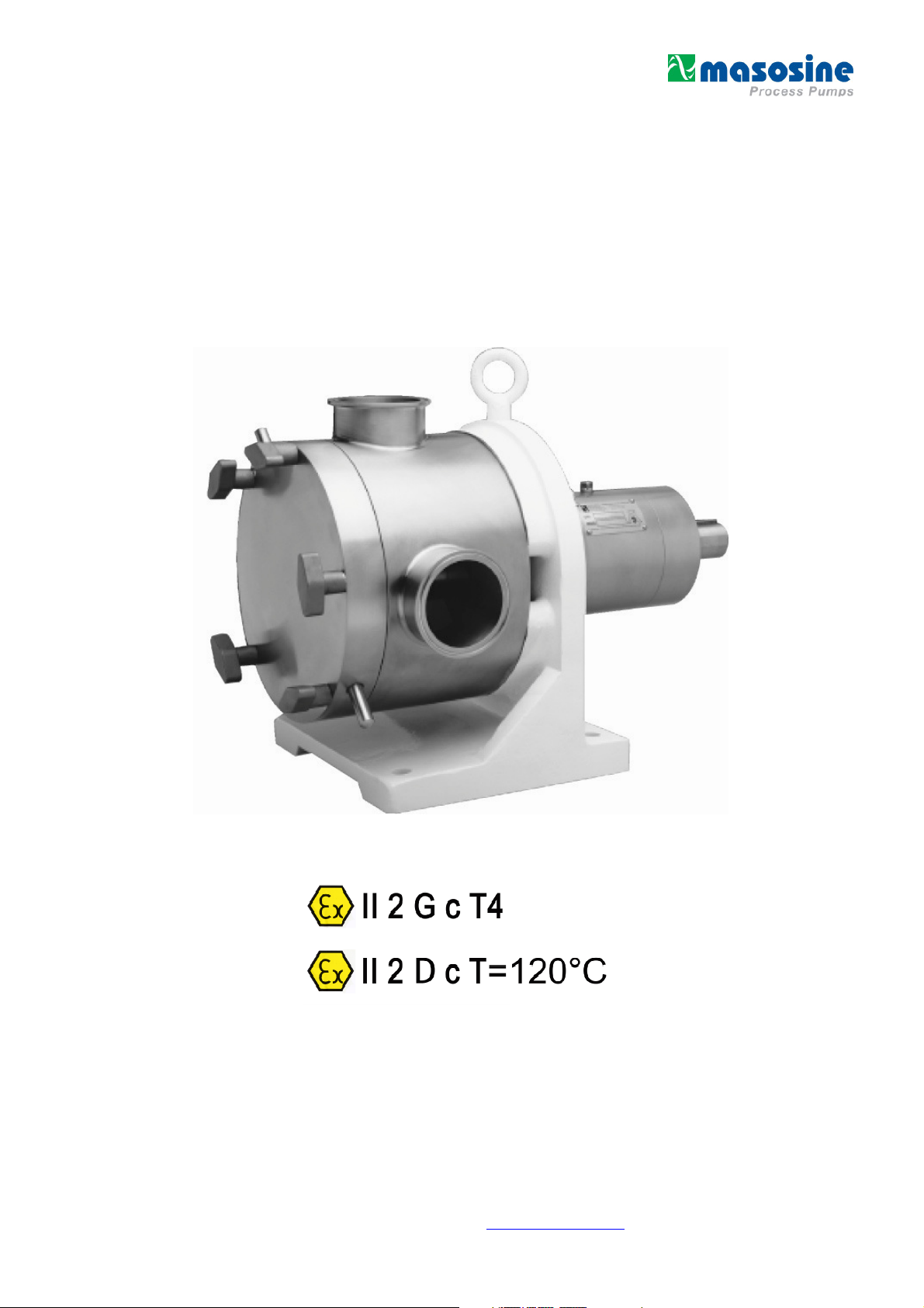
ATEX
Watson-Marlow MasoSine
MR-Series
Installation & Operation Manual
Revision 1.4 / August 2013
Visit our website at www.masosine.com 1
Page 2
Icons Used in this Manual
The following icons (symbols) are used to indicate specific types of information.
Good ideas to use. A reminder to do something.
Equipment use alert. Unless you follow these procedures correctly, the equipment
may be damaged.
Safety alert. Failure to follow these procedures can endanger the safety of you or
others.
Electrical hazard. Failure to follow these procedures can endanger the safety of
you or others.
Revision 1.4 / August 2013
Visit our website at www.masosine.com 2
Page 3

Contents
IMPORTANT SAFETY MEASURES ..................................................................................... 4
RECEIVING YOUR MASOSINE PUMP ................................................................................ 5
WARRANTY AND LIABILITY ............................................................................................... 5
INSTALLATION PROCEDURES .......................................................................................... 6
OPERATION GUIDELINES .................................................................................................. 7
WET END DISASSEMBLY ................................................................................................... 8
WET END ASSEMBLY ........................................................................................................10
POWER END DISASSEMBLY .............................................................................................11
POWER END ASSEMBLY ..................................................................................................12
SEAL SYSTEM - DISASSEMBLY AND ASSEMBLY ..........................................................14
SHIMMING FOR PROPER SHAFT LOCATION ..................................................................18
PUMP HOUSING ROTATION INSTRUCTIONS ..................................................................21
BEARING OIL LUBRICATION RECOMMENDATIONS .......................................................22
ASSEMBLY INSTRUCTIONS FOR INSTALLATION OF FRONT COVER HINGE ..............23
HOW TO USE THE REMOVEL TOOLS...............................................................................26
TORQUE SPECIFICATIONS ...............................................................................................27
MASOSINE PUMP WEIGHTS .............................................................................................27
TROUBLESHOOTING THE MASOSINE PUMP ..................................................................28
PRODUCT LINE ..................................................................................................................29
SOFTWARE MATERIAL GUIDE .........................................................................................30
SEAL OPTIONS...................................................................................................................32
CROSS SECTION AND PARTS ..........................................................................................35
INDEX OF FIGURES ...........................................................................................................49
INDEX OF TABLES .............................................................................................................49
SAFETY INSTRUCTIONS (ATEX) .......................................................................................50
OIL CHANGE .......................................................................................................................52
Revision 1.4 / August 2013
Visit our website at www.masosine.com 3
Page 4
Important Safety Measures
Note: It is important that this manual be read completely before attempting operation
or disassembly of the MASOSINE PUMP to ensure safety of personnel and to avoid
damage to the pump.
Be sure to give strict attention to the Installation and Operation sections of this
manual. These sections are intended to bring to the user's attention areas of bad
practice that may give rise to possible failure conditions with the equipment as
supplied.
Never place fingers, hands or other foreign objects into the MasoSine Pump during
operation as this could cause personal injury.
Never operate the MasoSine Pump with the front cover removed or loose as this
could cause fluid to spill out of the pump and could ultimately result in personal
injury.
Do not operate the MasoSine Pump without the coupling guard installed properly.
Clothing, body parts, tools or other loose items coming in contact with the
pump/drive shaft or coupling could result in severe personal injury or loss of life.
Before attempting to dismantle the MasoSine Pump, be sure that the power source
to the drive is disconnected or locked nut. Ensure that the electrical switch gear
cannot be operated while any work is being done on the pump.
Revision 1.4 / August 2013
Visit our website at www.masosine.com 4
Page 5

Receiving Your MasoSine Pump
NOTE: Your MasoSine Pump has been inspected at the factory prior to shipment. All pumps are
shipped ready for service, i.e. completely assembled. The bearing housings have been supplied with
oil in them.
Inspect the shipping container and pump for evidence of damage during shipment.
If damage is found:
Note the extent of the damage before unpacking the pump.
Photograph the damage, as this is very helpful in making any claims against the carrier.
A pump lost or damaged during shipment is the responsibility of the carrier. Watson-Marlow
MasoSine will assist in tracing any lost shipments.
After uncrating your MasoSine Pump:
1. Check to be sure that the suction and discharge nozzles are covered. If the nozzles protective
covers have come loose or have been removed during shipment, it is important that the pump
interior be inspected. Any debris found in the pump should be removed.
2. Check the nameplate data against the shipping papers and against your purchase order to insure
that the proper pump has been provided and that the materials of construction match your
specifications.
3. If applicable, check to see that the proper drive has been supplied, particularly with regard to the
supply voltage required.
4. Inspect the suction and discharge nozzles to be certain that they are free of scratches and that
they are clean of any foreign substances. The gasket seating surfaces should be inspected
carefully, especially for vacuum and suction lift applications.
5. Liner/seal housing removal tools have been provided to assist you with maintenance of the
MasoSine Pump. These tools (there should be two) can be found in the crating.
If there are any questions regarding receiving your pump, please contact Watson-Marlow MasoSine
at +49 (0)7062 9560-0
Warranty and Liability
Basically our “General sales and delivery conditions” apply. These are available to the operator at the
latest since conclusion of the contract.
Warranty and liability claims for personal and material damage are excluded if they are attributable to
one or several of the following causes:
- Use of the machine not as intended
- Incorrect installation, operation and maintenance of the machine
- Operating the machine with defective safety devices or not correctly attached or not functioning
safety and protective devices
- Non-compliance with the instructions in the operating instructions regarding
transport,
storage,
installation,
start-up,
operation, maintenance and setting of the machine.
- Unauthorized constructional changes to the machine
- Insufficient monitoring of machine parts subject to wear
- Incorrectly performed repairs
- Cases of catastrophe due to effect of foreign bodies and acts of God.
Revision 1.4 / August 2013
Visit our website at www.masosine.com 5
Page 6
The Watson-Marlow MasoSine grants no warranty on this documentation as well as no implicit
warranties on commercially customary quality and suitability for a certain application.
The Watson-Marlow MasoSine undertakes no liability for errors contained in it or consequential
damage occurring by chance arising due to the design, performance and the use of this
documentation.
This publication contains own information protected by copyright. All rights are reserved.
This publication may be neither photocopied, nor duplicated nor translated without previous
agreement of Watson-Marlow MasoSine. Rights reserved to make changes in these operating
instructions.
Installation Procedures
NOTE: Before attempting to operate your MasoSine Pump, work through the following items.
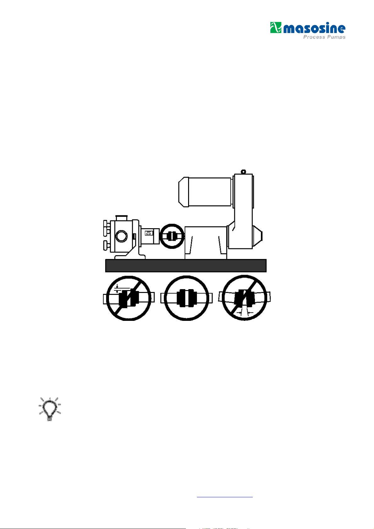
1. Check the coupling alignment between the drive and the pump. This should be done only after the
pump, drive and base have been fully anchored. Refer to
with the coupling, if applicable.
Figure 1
and the alignment sheet supplied
Figure 1 – Coupling Alignment
2. Be sure that the piping loads on the suction and discharge nozzles are not excessive. Flexible
connectors on both the suction and discharge side of the pump are recommended to eliminate
pipe stress or movement
3. Check to be sure that the pump and piping are free of foreign objects.
Caution: Do not use the MasoSine Pump to flush or clean the piping system as damage to the
pump may result.
4. Be sure to check all joint and piping connections to insure that they are tight and free of air leaks.
Suction leaks can cause the pump to run inefficiently.
5. Pressure gauges on both the suction and discharge side of the pump are highly recommended.
These gauges can often identify the source of system operational problems.
Revision 1.4 / August 2013
Visit our website at www.masosine.com 6
Page 7
Operation Guidelines
The following guidelines are important to the proper operation of your MasoSine Pump:
1. Check to be sure that the drive shaft rotation is compatible with the desired rotation of the pump
shaft.
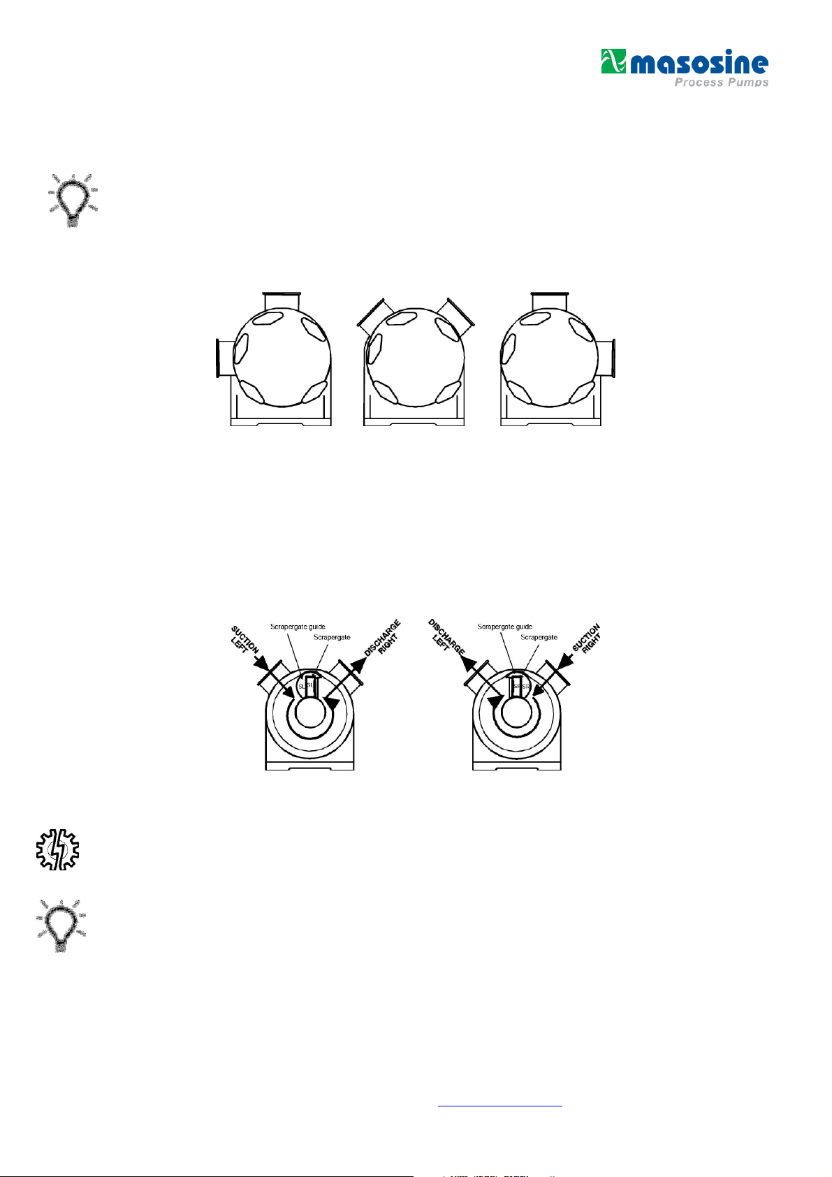
2. The suction and discharge nozzles on the pump housing will always remain 90° apart. However,
the pump housing can be rotated in 45° increments to suit your desired nozzle positioning and
process needs. Refer to
how to rotate the pump housing.
Figure 2
for the three positioning options and to page 22 for instructions on
Figure 2 – Nozzle Position
3. The application suction conditions determine the rotation of the pump shaft and the orientation of
the scrapergate and scrapergate guide.
NOTE: The MasoSine Pump can operate in either a clockwise or counterclockwise direction with
equal performance provided the scrapergate and scrapergate guide are installed properly. The
fluid will pass through a 270° arc that will transport it from suction to discharge. Refer to
Figure 3
and page 20 for scrapergate and scrapergate guide installation instructions.
Figure 3 - Rotation
4. Caution: Do not run the MasoSine Pump dry. Damage to the wet end parts may result. If using the
MasoSine Pump in conjunction with a variable speed drive, it is recommended to start the drive at
as low a speed as possible. Be certain that liquid is available to the suction side of the pump
before operating.
5. On suction lift applications, top suction nozzle orientation should be avoided, as it is very difficult
to remove air from the pump in this position. It is necessary to fill the pump with water or product
prior to starting the drive.
Revision 1.4 / August 2013
Visit our website at www.masosine.com 7
Page 8
Operation Guidelines, cont.
6. Be certain that all suction and discharge valves lines, etc. in the system are open and clear of
any clogs. This will prevent over pressurization of the pump. Warning: The MasoSine Pump is
not supplied with a relief valve and the maximum discharge pressure rating is 150 psi.
Exceeding this maximum pressure rating could result in severe personal injury.
7. The maximum MasoSine Pump operating speeds are:
MR-120 MR-125 MR-130 MR-135/MR-135RF MR-150/MR150RF
800 RPM 800 RPM 800 RPM 600 RPM 600 RPM
Warning: Exceeding the maximum speed rating for your MasoSine Pump could result in
severe personal injury or loss of life. Since some pumpages may be adversely affected by
operation at high rotor speeds, we recommend that you contact Watson-Marlow MasoSine
with pertinent application information before running at or near these speeds.
8. It is recommended that the MasoSine Pump wet end be fully disassembled for cleaning after
every use per the instructions in the Wet End Disassembly section of this manual. Sanitizing
the MasoSine Pump in a Clean-In-Place (CIP) system with a common disinfecting or rinsing
solution may not fully clean the wet end of the pump.
9. Warning: When pumping explosive, flammable or hazardous fluids, please contact the factory
for application assistance.
10. The MasoSine Pump airborne noise emissions do not exceed 70 dB(A).
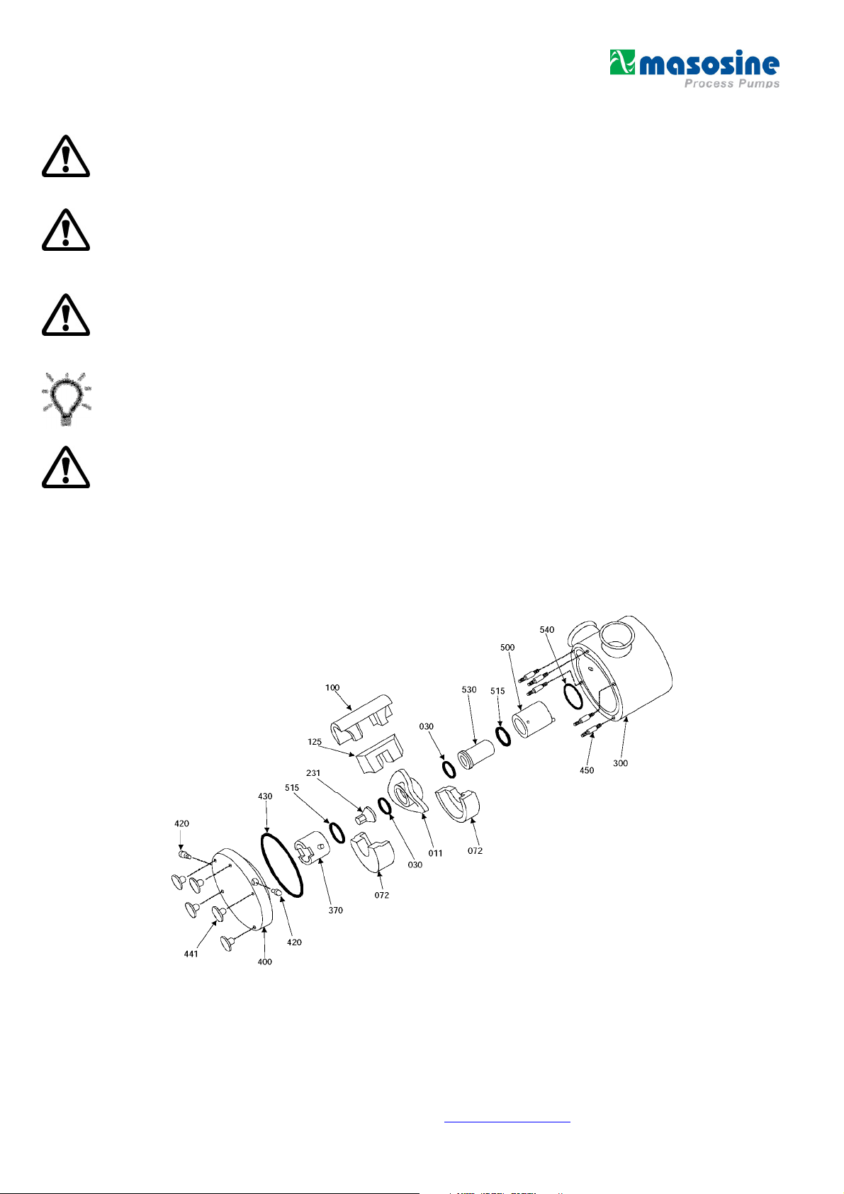
Wet End Disassembly
Reference the isometric drawing below for parts identification while following the wet end disassembly
and assembly steps.
Revision 1.4 / August 2013
Visit our website at www.masosine.com 8
Page 9
Wet End Disassembly, cont.
1. Remove the front cover, item 400, by removing the five wing nuts, item 441, and sliding the cover
off of the front cover studs, item 450. NOTE: Do not use a screwdriver or other prying
instrument to separate the cover from the housing. Damage to the stainless steel may
result. A soft hammer can be used to separate the cover from the housing by tapping on the front
cover pins, item 420, located on the outer diameter of the front cover.
2. The front support, item 370, may now be removed from the front cover for inspection and cleaning.
If the support is stainless steel, remove the dynamic face o-ring, item 515, from the groove.
3. Remove the front liner, item 072, by pulling with even pressure on both ends. Pulling with uneven
pressure may cause the liner to become lodged in the pump housing making it difficult to remove.
NOTE: Pumping of high temperature fluids may also make the liners difficult to remove due
to thermal expansion. If the pump has been running at a high temperature, allow it to cool before
removing the liner.
4. Remove the shaft nut, item 231, from the shaft, item 200. Wrench flats have been machined on
the rear of the shaft for the purpose of securing the shaft while removing the nut. The rotor o-ring,
item 030, can now be removed from the groove in the shaft nut.
5. Next, the rotor, item 011, the scrapergate, item 125, and the scrapergate guide, item 100, can be
pulled of the shaft and removed from the pump housing. This will require two hands.
6. Remove the rear liner, item 072. This is where the liner/ seal housing removal tools will be helpful
(refer to page 26-27). Insert the hooked ends of the liner pullers into the slots located on each end
of the liner. Again, apply even pressure on both ends to prevent the liner from lodging the pump
housing.
7. The lip seal housing, item 500, may now be removed, along with the shaft sleeve, item 530. The
liner/seal housing puller tools should be used here again (refer to pages 26-27). Simply insert the
pins on the pullers into the holes in the outer diameter of the seal housing, located 180° from each
other, and use the tool to lever the seal housing out of the pump housing. Refer to page 33-35,
Seal Options, for a diagram showing your specific seal arrangement. If the seal housing is
stainless steel, remove the dynamic face o-ring, item 515, from the groove. For further
disassembly procedures for your specific seal arrangement, refer to the seal system disassembly
section of this manual.
8. Remove the shaft sleeve, item 530, from the seal housing. The rotor o-ring, item 030, can then be
removed from the groove in the shaft sleeve.
9. The seal housing o-ring, item 540, may then be removed from the groove in the pump housing.
There is a small notch in the bore of the pump housing to facilitate easy removal of the o-ring.
10. Should removal of the pump housing, item 300, be required, remove the housing mounting bolts,
item 340, and housing mounting washers, item 345, which connect the pump housing to the power
frame, item 600. Warning: Suitable lifting equipment should be used when removing the
pump housing to ensure that personal injury or damage to pump components does not
occur.
Revision 1.4 / August 2013
Visit our website at www.masosine.com 9
Page 10

Wet End Assembly
1. Place the pump housing, item 300, onto the power frame, item 600, by fitting the opening in the
back of the pump housing over the shaft, item 200. NOTE: Be sure that the mating flanges of the
power frame and pump housing are free of any debris or nicks, as this may cause misalignment of
the rotor. Warning: Suitable lifting equipment should be used when installing the pump housing to
ensure that personal injury or damage to pump components does not occur.
2. Install the housing mounting washers, item 345, and housing mounting bolts, item 340, through
the rear of the power frame. The bolts should be tightened evenly and to the torque specification
provided on page 28.
3. Replace the seal housing o-ring, item 540, by fitting it into the groove in the rear of the pump
housing. Apply a food grade lubricant to the o-ring before installation.
4. If the lip seal housing, item 500, is stainless steel, replace the dynamic face o-ring, item 515, by
placing it into the groove at the end of the seal housing. Apply a food grade lubricant to the o-ring
before installing. Place the seal housing into the bore in the rear of the pump housing, item 300,
such that the removal holes on the outer diameter are exposed. NOTE: Lubricating the outer
diameter of the rear of the seal housing will promote easy assembly with the seal housing o-ring,
item 540. If the seal housing is stainless steel, the anti-rotation pin in the rear of the seal housing
must be sealed properly in the slot in the rear of the pump housing. To properly seat the seal
housing, place the rotor, item 011, and the shaft nut, item 231, over the shaft, item 200. Tighten
the shaft nut to force the seal housing past the seal housing o-ring. Remove the rotor and shaft
nut from the shaft before proceeding. For further assembly procedures for your specific seal
arrangement, refer to the seal system assembly section of this manual.
5. Replace one of the rotor o-rings, item 030, by placing it into the groove on the end of the shaft
sleeve, item 530. Apply a food grade lubricant to the o-ring before installing. The shaft sleeve my
then be fitted over the shaft and into the seal housing.
6. Install one of the liners, item 072, into the pump housing being sure to fit the liner between the two
anti-rotation pins located on the internal diameter of the pump housing. Apply even pressure to
both ends to prevent the liner from becoming lodged in the pump housing.
7. Place the scrapergate, item 125, into the scrapergate guide, item 100, being sure that the marked
ends (SL and SR) match up properly. Referencing page 20 of this manual, place the scrapergate
and scrapergate guide in the desired orientation. Using both hands, this assembly can then be
placed on the rotor, item 011, such that the opening in the scrapergate and scrapergate guide fit
over the rotor vane. Install this three-piece assembly in the pump by placing the scrapergate guide
into the bore located between the suction and discharge nozzle and fitting the rotor over the
splined section of the shaft. NOTE: There is no front or back to the rotor, so it can be inserted
either way. Once the rotor meets the rotor o-ring on the shaft sleeve, apply extra pressure to
insure that the rotor is seated over the o-ring.
8. Replace the other rotor o-ring, item 030, by placing it into the groove on the end of the shaft nut,
item 231. Apply a food grade lubricant to the o-ring before installing. The shaft nut can then be
tightened onto the shaft. Wrench flats have been machined on the rear of the shaft for the purpose
of securing the shaft while tightening the shaft nut. Torque the shaft nut to the specification listed
on page 28.
9. Install the other liner, item 072, into the pump housing being sure to fit the liner between the two
anti- rotation pins located on the internal diameter of the pump housing. Apply even pressure to
both ends such that the liner does not become lodged in the pump housing.
Revision 1.4 / August 2013
Visit our website at www.masosine.com 10
Page 11
Wet End Disassembly, cont.
10. The front cover o-ring, item 430, can then be placed into the groove on the front of the pump
housing. Applying a food grade lubricant to the o-ring will keep it from slipping out of the groove.
11. If the front support, item 370, is stainless steel, replace the dynamic face o-ring, item 515, by
placing it into the groove at the end of the front support. Apply a food grade lubricant to the o-ring
before installing. Place the front support into the bore in the front cover, item 400, with the slots
being installed first
12. Place the front cover and front support assembly onto the front of the pump housing by lining up
the front cover studs, item 450, with the corresponding holes in the cover. Front cover pins, item
420, have been placed on the outer diameter of the front cover to facilitate this.
13. Install the five wing nuts, item 441, by hand tightening them onto the front cover studs. The wing
nuts may be further tightened with a soft-headed hammer. NOTE: If the front cover does not seat
properly against the pump housing face, remove the cover and examine the internal components
checking for proper alignment.
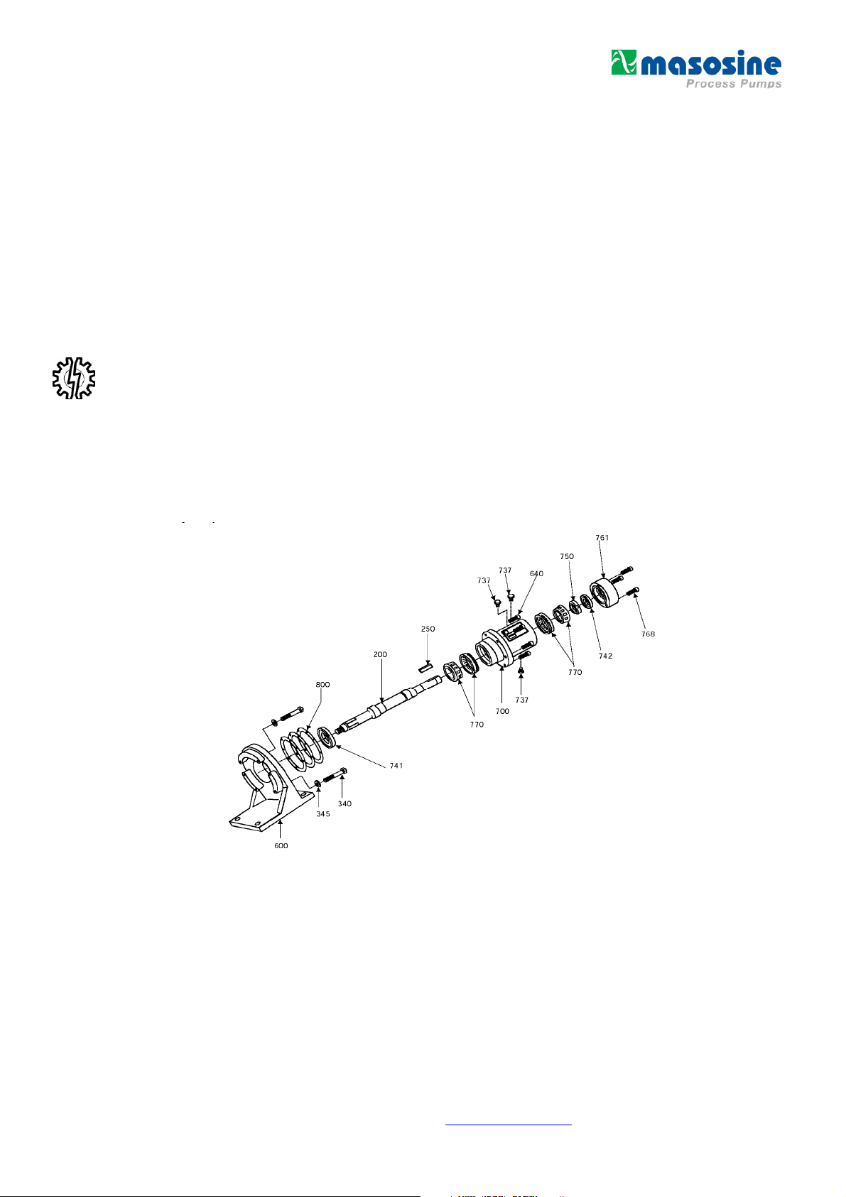
Power End Disassembly
Reference the isometric drawing below for parts identification while following the power end
disassembly an assembly steps.
1. Before beginning the power end disassembly, follow steps 1 through 11 in the wet end
disassembly section of this manual.
2. Drain the oil from the bearing housing, item 700, by removing the oil drain plug, item 737, located
on the bottom of the bearing housing.
Revision 1.4 / August 2013
Visit our website at www.masosine.com 11
Page 12
Power End Disassembly, cont.
3. Remove the bearing housing mounting cap screws, item 640, which connect the bearing housing,
item 700, to the power frame, item 600. The bearing housing may then be removed by pulling the
shaft, item 200, and bearing housing away from the power frame. NOTE: Be sure to support the
bearing housing such that the shaft will not be damaged when pulling it through the hole in
the power frame.
4. Remove the shims, item 800, which are located where the bearing housing meets the power
frame.
5. Remove the bearing housing cover cap screws, item 768, which connect the bearing housing
cover, item 761, to the bearing housing. The bearing housing cover can then be removed.
6. Using a punch and hammer or a press, remove the outboard oil seal, item 742, from the cover.
NOTE: Be careful not to damage the bearing housing cover when removing the seal.
7. Loosen the four small set screws located in the bearing locknut, item 750. The bearing locknut can
then be unscrewed and removed from the shaft.
8. Using a press, remove the shaft from the bearing housing by applying force to the key end of the
shaft. As the shaft is being forced out of the bearing housing, the rear tapered roller bearing inner
race, item 770, is being removed from the shaft. NOTE: The shaft will come free and drop out
of the bearing housing when the bearing is pressed out. Be sure to support the shaft such
that it will not be damaged.
9. Remove the inboard oil seal, item 741, by simply pulling it off of the shaft.
10. Remove the front tapered roller bearing inner race, item 770, by pressing the bearing off of the
shaft.
11. Using a punch and hammer or a press, remove the front and rear tapered roller bearing outer
races, item 770, from the bearing housing. NOTE: Be careful not to damage the internal
diameter of the bearing housing when removing the outer races.
Power End Assembly
1. Press the front and rear tapered roller bearing outer races, item 770, into the bearing housing,
item 700, being sure that the angled ends of the races face out of the housing. In the case of the
MR-150 and MR-150RF, the larger of the two outer races should be pressed into the flanged end
of the bearing housing. NOTE: Be careful not to damage the race surfaces, as this may lead to
premature bearing failure.
2. For easy bearing assembly, lock the shaft, item 200, into a vertical position with the key end of the
shaft on top. Heat one of the tapered roller bearing inner races (in the case of the MR-150 and
MR- 150RF, the larger of the two bearings), item 770, to a temperature of 250°F. Thermal
expansion of the bearing will allow it to fit into the shaft. NOTE: Do not overheat the inner race,
as this will distort the roller support. While the bearing is hot, fit it onto the shaft until it
reaches the step, with the tapered section facing upward.
3. Place the bearing housing, item 700, flanged section first, over the shaft. This will seat the front
bearing inner and outer races.
4. Heat the other tapered roller bearing inner race, item 770, to a temperature of 250°F. While the
bearing is hot, place it onto the shaft with the tapered section facing down into the bearing
housing. This will seat the back bearing inner and outer races.
Revision 1.4 / August 2013
Visit our website at www.masosine.com 12
Page 13
Power End Assembly, cont.
5. With the bearing still hot, tighten the bearing locknut, item 750, onto the shaft, only enough to
eliminate any float between the shaft and the bearing housing. NOTE: The holes for the set
screws must be facing upward or out of the bearing housing when the bearing locknut is
installed. While tightening the bearing locknut, rotate the bearing housing a few times to
insure that the bearings have seated properly.
6. After allowing the assembly to cool, tighten the bearing locknut until the torque required to turn the
shaft falls within the following range of your specific pump model:
MR-120 and MR-125 = 1 to 3 in lbs
MR-130 and MR-135 and MR-135RF = 6 to 8 in lbs
MR-150 and MR-150RF = 8 to 10 in lbs
This requires tightening the shaft nut, item 231, onto the shaft, item 200, and using a torque
wrench to measure the torque required to turn the shaft. NOTE: Remember, this is the torque
required to turn the shaft. The actual torque required to turn the bearing locknut is much
greater.
7. Tighten the four set screws on the bearing locknut.
8. Press the outboard oil seal, item 742, into the bearing housing cover, item 761, with the lip section
of the seal facing outward. Be sure to lubricate the inner and outer diameter of the lip seal.
9. Apply a quality gasket sealant to the mating surface of the bearing housing cover, item 761, and
the bearing housing, item 700. Fit the bearing housing cover onto the bearing housing while lining
up the holes for the bearing housing cover cap screws, item 768. Fit the bearing housing cover
cap screws into the holes and tighten to the torque specification provided on page 28.
10. Press the inboard oil seal, item 741, into the bearing housing by fitting it, lip section first, over the
wet end of the shaft. Be sure to lubricate the inner and outer diameter of the lip seal.
11. Clean the mating surfaces between the bearing housing, item 700, and the power frame, item 600,
to insure that no debris is between the parts. Fit the bearing housing onto the power frame while
lining up the holes for the bearing housing mounting cap screws, item 640. The bearing housing
must be oriented such that the drain plug, item 737, is located at the bottom. NOTE: Be sure to
support the bearing housing such that the shaft will not be damaged while fitting it through
the hole in the power frame. Fit the bearing housing mounting cap screws into the holes
and tighten to the torque specification provided on page 28.
12. Install and tighten the drain plug, item 737.
13. Remove the oil fill plug and oil level plug, items 737. Fill the bearing housing with oil until the oil is
visible through the level hole. Refer to page 23 for oil lubrication recommendations. NOTE: Fill
the bearing housing with oil only to the oil level hole, as overfilling may cause the bearings
to fail prematurely. Replace and tighten the oil fill and oil level plugs.
14. Before replacing the parts in the wet end of the pump, refer to page19 for shimming instructions.
NOTE: The bearing housing must always be shimmed when the bearings are changed or
the bearing housing is removed for the purpose of properly locating the rotor in the center
of the pump.
Revision 1.4 / August 2013
Visit our website at www.masosine.com 13
Page 14
Seal System - Disassembly and Assembly
A. Lip Seal
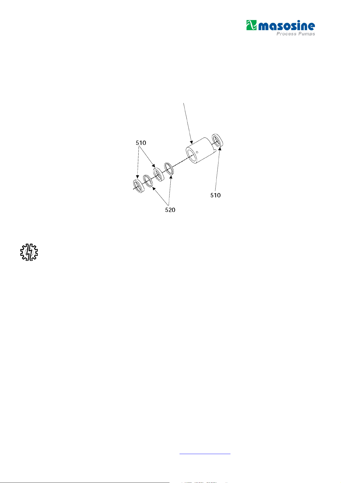
Reference the isometric drawing in
disassembly and assembly steps.
Figure 4
for parts identification while following the lip seal
506
Figure 4 – Lip Seal Disassembly / Assembly
Lip Seal Disassembly
1. Using a punch and hammer, remove the single lip seal, item 510, located in the rear of the lip seal
housing, item 506. NOTE: Be careful not to damage the inner diameter of the housing when
removing the seal.
2. Turn the seal housing upside down and press the remaining two lip seals, item 510, and the two
support rings, item 520, out of the seal housing using the press plug diameter for your specific
model listed in
3. . The lip seals should be discarded.
Table 1 – Lip Seal, Press (OUT) Plug Diameters
MR-120 = 1-3/8" or 34.9 mm
MR-125 = 1-7/8” or 47.6 mm
MR-130 = 2-3/8” or 60.3 mm
MR-135 = 2-3/4” or 69.8 mm
MR-150 = 3-1/2” or 88,9 mm
NOTE: Be careful not to damage the support rings, as these will be used again.
Lip Seal Assembly
1. Apply a food grade lubricant to the inner diameter of the lip seal housing, item 506. This should be
done to both ends of the housing.
Revision 1.4 / August 2013
Visit our website at www.masosine.com 14
Page 15
Seal System - Disassembly and Assembly, cont.
2. Place the seal housing in a press with the removal holes at the top of the housing. This side of the
seal housing will face into the wet end of the pump. Insert one support ring, item 520, into the seal
housing such that the flat surface of the ring rests on the step in the housing. This will not require
a press.
3. Press one of the lip seals, item 510, into the seal housing with the lip side of the seal facing out of
the housing using the press plug diameter listed in Table 2 for your specific pump model. Press
the seal in until it fits securely over the support ring.
Table 2 – Lip Seal, Press (INTO) Plug Diameters
MR-120 = 1-9/16” or 39.6 mm
MR-125 = 2-7/32” or 56.3 mm
MR-130 = 2-5/8” or 66.6 mm
MR-135 = 3” or 76.2 mm
MR-150 = 3-29/32” or 99.2 mm
NOTE: Apply even pressure to the lip seal to prevent it from lodging sideways in the housing
4. Insert the other support ring, item 520, into the seal housing such that the flat surface of the ring
rests on the lip seal. This will not require a press.
.
5. Press the second lip seal, item 510, into the seal housing with the lip side of the seal facing out of
the housing using the press plug diameter listed in Table 2 for your specific pump model. Press
the seal in until it fits securely over the support ring. NOTE: Apply even pressure to the lip seal
to prevent it from lodging sideways in the housing
6. Turn the seal housing over such that the removal holes in the housing are at the bottom. This side
of the seal housing will face the power end of the pump. Press the third lip seal, item 510, into the
seal housing with the lip side of the seal facing out of the housing. Press the lip seal in until the flat
side of the seal rests on the step in the seal housing. NOTE: Apply even pressure to the lip seal
to prevent it from lodging sideways in the housing
B. O-Ring Seal
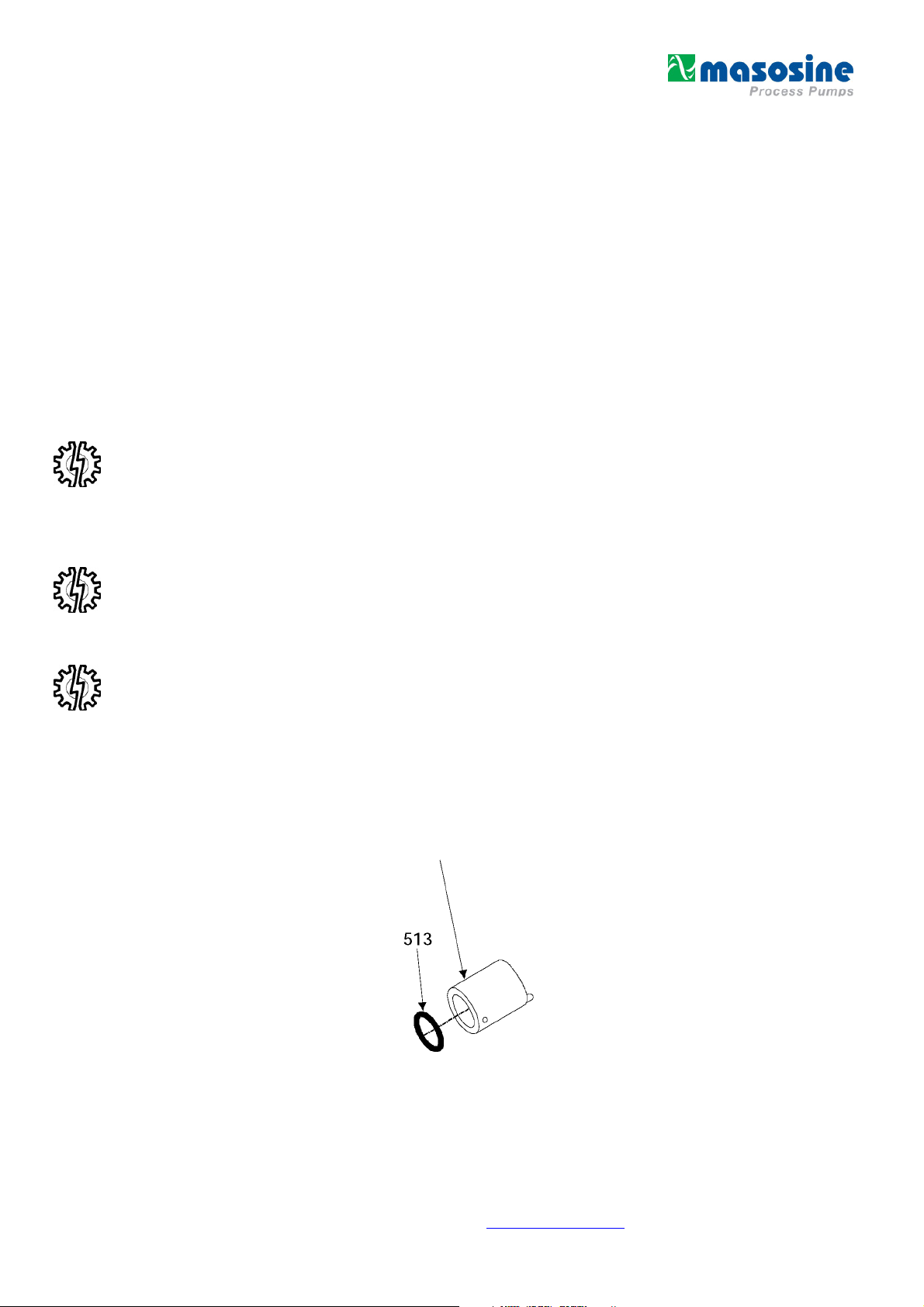
Reference the isometric drawing in
seal disassembly and assembly steps.
Figure 5 – O-Ring Seal
for parts identification while following the o-ring
620
Revision 1.4 / August 2013
Figure 5 – O-Ring Seal Disassembly / Assembly
Visit our website at www.masosine.com 15
Page 16
Seal System – Disassembly and Assembly, cont.
O-ring Seal Disassembly
1. Remove the dynamic radial o-ring, item 513, from the inner diameter of the o-ring seal housing,
item 620.
O-ring Seal Assembly
1. Replace the dynamic radial o-ring, item 513, by placing it into the groove on the inner diameter of
the o-ring seal housing, item 620. Apply a food grade lubricant to the inner diameter of the o-ring.
C. Mechanical Seal
Reference the isometric drawing in
disassembly and assembly steps.
Figure 6
for parts identification while following the mechanical seal
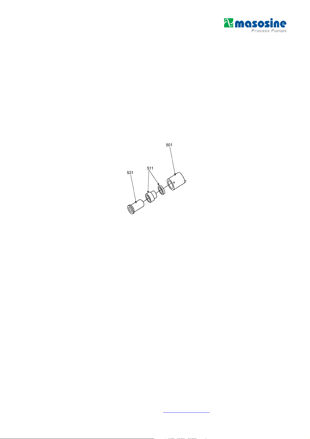
Figure 6 – Mechanical Disassembly / Assembly
Mechanical Seal Disassembly
1. Remove the shaft sleeve, item 531, from the mechanical seal housing, item 501. Slide the
mechanical seal, item 511, off of the shaft sleeve.
2. To remove the stationary ceramic face of the mechanical seal, item 511, place the seal housing in
a press with the removal holes at the bottom of the housing. Press the face out of the housing
using the press plug diameter listed in
Table 3
Table 3 – Mechnical, Press (OUT) Plug Diameters
for your specific pump model.
MR-120 = 1-1/2” or 38.1 mm
MR-125 = 1-3/4” or 44.4 mm
MR-130 = 2-1/8” or 53.9 mm
MR-135 = 2-1/8” or 53.9 mm
Mechanical Seal Assembly
1. Apply a food grade lubricant to the inner diameter of the mechanical seal housing, item 501.
MR-150 = 3-7/16” or 87.3 mm
2. Place the mechanical seal housing, item 501, into a press with the removal holes at the top of the
housing. Press the stationary ceramic face of the mechanical seal, item 511, into the seal housing
until it reaches the step at the rear of the housing using the press plug diameter listed in
Table 4
for
your specific pump model.
Revision 1.4 / August 2013
Visit our website at www.masosine.com 16
Page 17

Seal System – Disassembly and Assembly, cont.
It can be fitted in either way, as there is no front and back side. NOTE: Apply even pressure to
the stationary face so as not to damage the o-ring located on the outer diameter of the face.
3. Install the mechanical seal, item 511, onto the shaft sleeve, item 531, such that the carbon face
slides over the sleeve last. The slot on the end of the mechanical seal opposite the carbon face
must be installed over the drive pin on the shaft sleeve.
4. Fit the mechanical seal and shaft sleeve assembly into the seal housing with the seal being
installed first. This will mate the stationary ceramic face to the carbon face.
5. For instructions regarding the disassembly and assembly procedures for the double lip seal or the
o- ring seal with flush, please contact Watson-Marlow MasoSine at +49 (0)7062 9560-0
Table 4 – Mechanical, Press (INTO) Plug Diameters
MR-120 = 1-5/8” or 41.2 mm
MR-125 = 2” or 50.8 mm
MR-130 = 2-5/8” or 66.6 mm
MR-135 = 2-5/8” or 66.6 mm
MR-150 = 3-5/8” or 92.1 mm
Revision 1.4 / August 2013
Visit our website at www.masosine.com 17
Page 18

Shimming for Proper Shaft Location
Proper shaft location will insure that the rotor is positioned in the center of the wet end of the pump.
Failure to position the rotor correctly may result in excessive and premature wear to the wet end parts.
Here are the steps necessary to shim your MasoSine Pump.
1. Install the bearing housing, item 700, into the power frame, item 600, and tighten the bearing
housing mounting cap screws, item 640. Install the pump housing, item 300, on the power frame
and tighten the housing mounting bolts, item 340. The mating surfaces between the parts should
be cleaned to eliminate any debris or burrs. NOTE: Be sure that both the cap screws and bolts
are tightened to the torque specification provided on page 28.
2. Install the shaft sleeve, item 530, over the wet end of the shaft, item 200 as shown in
Figure 7
below. The shaft sleeve should be pushed onto the shaft until it reaches the shoulder. The mating
surfaces between the sleeve and the shaft should be cleaned to eliminate any debris or burrs.
3. Using a depth micrometer, or other tool which measures increments of 0.001", measure the
dimension from the shoulder on the shaft sleeve to the back face of the pump housing as shown in
Figure 7
.
4. Subtract the measurement which you received in step 3 from the "X" dimension listed in the chart
below for your pump model. The result will equal the amount of shim necessary to install between
the bearing housing and power frame. NOTE: If the dimensions listed are considerably
different from your measurement, please contact MasoSine Pump Technical Services at
303-425-0800. Remove the shaft sleeve from the shaft. Loosen and remove the bearing
housing mounting cap screws. Remove the bearing housing and shaft assembly from the
power frame.
5. Remove the shaft sleeve from the shaft. Loosen and remove the bearing housing mounting cap
screws. Remove the bearing housing and shaft assembly from the power frame.
6. Install the correct thickness of shim, item 800, required to fit within the tolerance listed in the chart
below for your pump model. Place the shim over the bearing housing flange such that the holes in
the shim are lined up with the holes on the bearing housing flange.
7. Install the bearing housing into the power frame and tighten the bearing housing mounting cap
screws. NOTE: Be sure that the cap screws are tightened to the torque specification
provided on page 28. Verify your measurements.
Revision 1.4 / August 2013
Figure 7 – “X“ Dimension
Visit our website at www.masosine.com 18
Page 19

Scrapergate and Scrapergate Guide Installation Instructions
The scrapergate has been designed with an angle on each of its ends and a channel on the discharge
side for optimum performance and life span. It is used to separate the suction and discharge sides of
the pump. To ensure proper operation, it is essential that these installation instructions be followed
carefully.
The scrapergate has a suction side and a discharge side as shown in
the scrapergate is wider on the suction side than on the discharge side. One of the angled ends of the
scragergate has been stamped "SL" for suction left and the other has been stamped "SR" for suction
right. The scrapergate guide also has a suction side and a discharge side as shown in
viewed from the end, the scrapergate guide has a rounded, wider section which corresponds to the
suction side and a thin, flat section which corresponds to the discharge side. The ends of the
scrapergate guide has also been stamped with the markings "SL" and "SR".
Suction Side
Discharge Side
Figure 8
. If viewed from the top,
Figure 9
. If
Figure 8 – Scrapergate Installation Instractions
End View
Discharge Side
Suction Side
Figure 9 – Scrapergate Guide Installation Instructions
Revision 1.4 / August 2013
Visit our website at www.masosine.com 19
Page 20

Scrapergate and Scrapergate Guide Installation Instructions
When inserting the scrapergate into the scrapergate guide, the markings on the ends of both parts
must match. This ensures that the wider side of the scrapergate will contact the wider section of the
scrapergate guide.
Your suction conditions coupled with the nozzle orientation determine how the scrapergate and
scrapergate guide should be installed in the MasoSine Pump. The two most common MasoSine Pump
flow conditions are shown in
located), if the product were to enter the MasoSine Pump through the nozzle located at the 12 o'clock
position and leave the pump through the nozzle located at the 3 o'clock position as depicted on the left
in
Figure 10
be installed with the "SL" markings facing out towards the front cover of the pump. This corresponds to
a counterclockwise rotation of the shaft.
When viewing the pump from the front, if the product were to enter the MasoSine Pump through the
nozzle located at the 3 o'clock position and leave the pump through the nozzle located at the 12
o'clock position as depicted on the right in
scrapergate and scrapergate guide should be installed with the "SR" markings facing out towards the
front cover of the pump. This corresponds to a clockwise rotation of the shaft.
To change the orientation of the scrapergate and scrapergate guide, follow steps 1 through 6 of the
Wet End Disassembly section of this manual. Rotate the scrapergate and scrapergate guide and then
follow steps 7 throughl 3 of the Wet End Assembly section of this manual.
the suction left condition would apply. Thus, the scrapergate and scrapergate guide should
Figure 10
. When viewing the pump from the front (where the front cover is
Figure 10
, the suction right condition would apply. Thus the
Figure 10 – Scrapergate (Guide) Installation Instructions
Revision 1.4 / August 2013
Visit our website at www.masosine.com 20
Page 21

Pump Housing Rotation Instructions
The pump housing can be rotated to locate the inlet and outlet nozzles in the three different positions
shown in
shaft.
diagram, the inlet and outlet nozzles have been marked "S" to depict suction and "D" to depict
discharge.
To rotate the pump housing to fit your inlet and outlet piping conditions, simply follow these
instructions:
1. Remove all of the parts from the wet end of the pump. Refer to the Wet End Disassembly section
2. Loosen and remove the housing mounting bolts, item 340, and the housing mounting washers,
Figure 11
Figure 11
. This allows for six different operating conditions based on the rotation of the pump
shows the various pumping orientations with arrows depicting shaft rotation. In the
of this manual.
item 345, which attach the pump housing, item 300, to the power frame, item 600. Warning:
Suitable lifting equipment should be used when removing and installing the pump housing
to ensure that personal injury or damage to pump components does not occur.
Figure 11 – Front Views (Rotation Instructions)
3. Rotate the pump housing such that the nozzles are in a desired position. Holes have already been
drilled in the rear of the pump housing to facilitate any position of the nozzles.
4. Place the pump housing back onto the power frame being sure to align the bolt holes of both
parts. Install the housing mounting washers and bolts and tighten to the torque specification on
page 28. NOTE: Failure to tighten the bolts to the specification may cause damage to the
wet end parts, as the rotor will not be centered in the housing properly.
5. Replace the parts in the wet end of the pump. Refer to the Wet End Assembly section of this
manual. Be sure to install the scrapergate and scrapergate guide in the correct position. Refer to
page 20.
Revision 1.4 / August 2013
Visit our website at www.masosine.com 21
Page 22

Bearing Oil Lubrication Recommendations
There are three plugs located in the bearing housing as shown in
bearings are properly lubricated, remove the level plug. If oil is not visible, remove the fill plug and fill
the bearing housing until oil is visible through the level plug hole. Replace both plugs.
For proper lubrication and maintenance, use the following guidelines:
1. Use Lubriplate FMO 2400 AW gear oil or equivalent food grade oil in the bearing housing.
2. Check the oil level weekly. Be sure that all plugs are fully tightened when installing to prevent
water or other foreign matter from entering the bearing housing.
3. Change the oil every 5000 hours of operation for ambient temperature pumpage. Change the oil
every 2000 hours of operation for pumpage above 150°F.
4. Fill the bearing housing with oil only to the level hole, as overfilling may cause the bearings to fail
prematurely.
Figure 12
below. To determine if the
REAR VIEW
Figure 12 – Oil Lubrication
Revision 1.4 / August 2013
Visit our website at www.masosine.com 22
Page 23

Assembly Instructions for Installation of Front Cover Hinge
The front cover hinge is available for the MR-135 and the MR-150 MasoSine Pump. It allows for the
front cover to be hinged to the pump housing for easier maintenance. When assembling the front
cover hinge, follow the steps below and refer to
only when the front cover is attached to the pump housing.
1. Attach the ring arm, item 1a or 1b, to the top nozzle of the pump and insert the two cap screws,
item 3, into the slots on the diameter of the ring. Do not tighten the cap screws completely. NOTE:
The ring arm is two pieces, a half ring and a half ring with a rectangular bar welded to it. The ring
arm can point to either side of the pump depending on which way you prefer the front cover to
swing away from the pump housing.
2. Stack the following items, with their holes aligned, above the hole at the end of the ring arm in the
order listed: a.) one plastic washer, item 4, b.) the pivot arm, item 2, using the smaller diameter
hole c.) the other plastic washer, item 4, and d.) the stainless steel washer, item 5. Install the bolt,
item 5, by fitting it through the stacked items and threading it into the hole on the right arm.
Tighten the bolt until the parts are secure but loose enough to allow rotation of the pivot arm.
Thread the hex nut, item 7, onto the bolt and tighten securely to lock the bolt in place.
3. Attach the rod end, item 8, with two washers, item 11, on either side of the ball, to the front cover
using the bolt, item 10. The bolt will thread into the tapped hole on the front cover.
Figure 13
and the associated parts list. Install the hinge
4. Place the washer, item 11, on the bolt, item 9, and insert the bolt through the hole on the end of
the pivot arm. Thread the hex nut, item 12, onto the end of the bolt, but do not tighten.
5. With the rod end held upwards toward the pivot arm, thread the bolt into the hole in the rod end.
6. Rotate the ring arm until the rod end is vertical as shown in
Figure 13
. Tighten the cap screws until
the ring arm is secure.
7. Tighten the bolt which connects the pivot arm to the rod end until the head comes into contact with
the washer.
8. Remove the wing nuts and front cover. By either tightening or loosening the hex nut on top of the
rod end or adjusting the alignment of the ring arm, the height of the front cover when hanging can
be modified to ease assembly.
Two holes have been drilled and tapped in the face of the front cover to house the bolt which
holds the front cover onto the hinge assembly. One of the holes will not be used depending on the
location of the hinge assembly and the orientation of the inlet and outlet nozzles. This hole can be
fitted with a 3/8 - 16 x /" bolt.
Revision 1.4 / August 2013
Visit our website at www.masosine.com 23
Page 24

Assembly Instructions for Installation of Front Cover Hinge, cont.
Figure 13 – Front Cover Hinge
Item Description Part Number Qty
1a* Ring Arm (MR-150) 050P460.1304A1 1
1b* Ring Arm (MR-135) 035P460.1304A1 1
2 Pivot Arm 035P461.1304A1 1
3 Cap Screw 035P426.1300A1 2
4 Washer, Plastic, 3/8 035P463.2636A1 2
5 Washer, SS, 3/8 035P463.1304A1 1
6 Bolt, 3/8-16 x 1-3/4 035P464.1300A1 1
7 Hex Nut, 3/8 – 16 035P465.1300A1 1
8 Rod End, Female 035P466.1303A1 1
9 Bolt, 3/8-24 x 1-1/4 035P467.1300A1 1
10 Bolt, 3/8-16 x 1-1/4 035P468.1300A1 1
11 Washer, 3/8 035P469.1300A1 5
12 Hex Nut, 3/8 – 24 035P470.1300A1 1
*For the MR-150, use item 1 a; for the MR-135, use item 1 b
Revision 1.4 / August 2013
Visit our website at www.masosine.com 24
Page 25

How to use the Removal Tools
Removal tools are supplied with every new MasoSine Pump. The tools are shaped like skate blades
and have a pin extending from one end (see
Figure 14
). These tools are used for removing the rear liner
and the seal housing
FRONT VIEW SIDE
VIEW
To use the tool remove the seal housing from the pump, simply insert the pin at the end of the tool into
the hole on the outer diameter of the seal housing (see
seal housing, 180° apart, to facilitate the use of both tools. By applying downward pressure to the
hooked ends of the tools, the seal housing will be pulled from the rear of the pump housing. Always
use both tools when removing the seal housing to prevent it from wedging in the pump housing.
Figure 14 – Removal Tools
Figure 15
). Two holes have been drilled in the
Revision 1.4 / August 2013
Figure 15 – Remove the Seal Housing
Visit our website at www.masosine.com 25
Page 26

How to use the Removel Tools
To use the tool to remove the rear liner from the pump housing, simply insert the hooked ends of the
tools into the slotted ends of the liner and pull forward (See
pressure when removing the liner to prevent the liner from wedging in the pump housing.
Figure 16
). Pull on both tools with even
Figure 16 – Remove the Liner
Revision 1.4 / August 2013
Visit our website at www.masosine.com 26
Page 27

Torque Specifications
Pump Model Rotor Nut
Housing
Mounting Bolt
Bearing
Housing
Mounting
Cap Screw
Bearing
Housing
Cover Cap
Screw
Wing Nut
MR-120 40 54 18 24 14 19 4 5 14 19
MR-125 60 81 18 24 14 19 4 5 14 19
MR-130 60 81 18 24 18 24 8 11 18 24
MR-135
MR-135RF
MR-150
MR-150RF
ft•lbs N•m ft•lbs N•m ft•lbs N•m ft•lbs N•m ft•lbs N•m
80 108 18 24 18 24 8 11 18 24
100 135 18 24 25 34 14 19 25 34
MasoSine Pump Weights
Pump Model Pump Only Pump w/Box & Skid
MR-120
MR-125
MR-130
68 lbs.
31 kg.
125 lbs.
57 kg.
240 lbs.
109 kg.
74 lbs.
34 kg.
145 lbs.
66 kg.
265 lbs.
121 kg.
MR-135/MR-135RF
MR-150/MR-150RF
270 lbs.
123 kg.
460 lbs.
209 kg.
295 lbs.
134 kg.
475 lbs.
216 kg.
Revision 1.4 / August 2013
Visit our website at www.masosine.com 27
Page 28

Troubleshooting the MasoSine Pump
Problem Possible Causes Remedy
Inadequate Flow
Loss of Performance
Leaks
1. Incorrect shaft rotation
2. Scrapergate installation
3. Air leaks – external, internal
(loose fittings, lip seals)
1. Worn Scrapergate
2. Scrapergate support of seal
housing worn where
scrapergate shuttles
3. Worn Liners
1. O-rings (pinched, cut, missing)
2. Lip seals or seal housing
damages
3. Grooves in shaft sleeve from
abrasive applications or high
discharge pressure
1. (A) Check rotation
(B) Change wiring
2. Change Scrapergate & Guide
3. (A) Tighten fittings , i.e. Tri Clamp
(B) Replace worn lip seals or
o-rings
1. Check for wear & replace
2. Rotate to get a clean spot
3. Replace if worn
1. Visual inspection – replace
2. Rebuilt or replace assembly
3A.Check system for discharge
pressure problems
3B.Consider hard coating shaftsleeve
Accelerated Wear
Revision 1.4 / August 2013
1. Speed or abrasion
2. Excessive discharge pressure
(>150 PSIG)
3. Dry Run
Visit our website at www.masosine.com 28
1. (A) Decrease pump speed
(B) Use larger pump
2. (A) Increase line size
(B) Check valves
(C) Check viscosity & line losses
3. (A) Recommend level control
(B) Change internals
Page 29

Max.
Max.
Product Line
MASOSINE PUMP SPECIFICATIONS
Displacement
(Gallons/Revolution)
Model
SPS1
MR-120
MR-125
MR-130
MR-135
MR-135RF
MR-150*
MR-150RF*
SPS-6 (2)
RF models incorporate rectangular flanges on the suction side and bevel seat nozzles on the
discharge side.
NOTE:
(CC/Revolution)
.015 1x1 3/16
53 25x25 4.7
.03 2x2 1/4
106 50x50 6.5
.06 2 1/2x 2 2/2 1/2
224 63.5x63.5 12.5
.124 3x3 3/4
470 75x75 19
.23 3x3 1 1/4
875 75x75 31
.23 (2 1/2x9 1/4*)x3 1 1/4
875 (34x235*)x75 31
.47 4x4 2
1,784 100x100 50
.47 (3 1/2x11*)x4 2
1,784 (90x280*)x100 50
.67 6x6 2 1/2
2,544 152x152 63
Inlet/Outlet
(Inches) (MM)
Particle Size
(Inches)
(MM)
Capacity
(GPM)
(L/H)
15
3,400
24
5,450
48
10,900
99
22,485
138
31,343
138
31,343
282
64,049
282
64,049
402
91,304
Max.
Speed
(RPM)
1000
800
800
800
600
600
600
600
600
1. This is a guideline only, consult the factory when approaching maximum values for particulate
size, capacity or pump speed.
2. The SPS-1 and SPS-6 are not covered by this manual.
Revision 1.4 / August 2013
Visit our website at www.masosine.com 29
Page 30

SOFTWARE MATERIAL GUIDE
Software
Material
PBT
Description Color Advantages Disadvantages
Polybutylene
Terephthalate
PPS Polyphenylsulfid Blue
Polyamid
HTP
Polyamide
Reinforced
Polyetherimide
Off White
Off White
LINERS
White
Max.
Ratings
Good Performance
Low Cost
High Temperature
Abrasives
190° F
150 psi
High Temperature
Good Performance
Chemical Resistance
Severe Abrasives
250° F
225 psi
SPS-1 / SPS-6
For use with
SPS-1 / SPS-6
High Temperature
Severe Abrasives
200° F
150 psi
Good Performance Severe Abrasives 300° F
Stainless
Steel
Stainless
Steel
Silver
SCRAPERGATES
UHMW
Peek Polyetheretherketon Black
Polyamid Polyamide Off White
Sinar
Ultra High Molecular
Weight Polyethylene
Reinforced
Nylon
White Low Cost
Yellow
High Temperature
Abrasives
High Temperature
Chemical Resistance
SPS-1 / SPS-6
For use with
SPS-1 / SPS-6
High Temperature
Abrasives
Higher Cost
High Temperature
High Pressure
Higher Cost
High Temperature
Severe Abrasives
Higher Cost
300° F
225 psi
150° F
100 psi
275° F
225 psi
200° F
225 psi
300° F
150 psi
Revision 1.4 / August 2013
Visit our website at www.masosine.com 30
Page 31

SHAFT SLEEVES
316 SS
Hard
Coated
NOTE: The dynamic radial o-ring seal assembly requires the hard coated shaft sleeve.
Stainless
Steel
Ceramic Oxide
Coated Stainless
Silver
Black
High Temperature
Low Cost
Abrasives
High Pressure
Abrasives
Higher Cost
LIP SEALS & O-RINGS
Buna Elastomer Black
Viton Elastomer Brown
Abrasives
Low Cost
High Temperature
Chemical Resistance
High Temperature
Severe Abrasives
Higher Cost
300° F
150 psi
300° F
150 psi
200° F
150 psi
300° F
150 psi
EPDM Elastomer Black
NOTE: EPDM material is not available for the dynamic radial or dynamic face o-rings.
Chemical Resistance
Higher Cost
300° F
150 psi
Revision 1.4 / August 2013
Visit our website at www.masosine.com 31
Page 32

Seal Options
1. Lip Seal Assembly
This is the standard seal which is used in the
MasoSine Pump. It consists of three lip seals,
two of which are used to seal product into the
pump, and one which is used to prevent the
pump from pulling air. The two front lip seals
incorporate a stainless steel support ring
enabling the assembly to withstand pressures
from the product side up to 150 psi.
Figure 17
shows a list of parts and an accompanying
cross section drawing which makes up the lip
seal assembly
374
506
2. O-Ring Seal Assembly
The o-ring seal assembly uses a single
elastomeric o- ring to seal the product from
escaping the pump housing. This type of seal
arrangement can be used only when product
pressures do not exceed 100 psi and the
shaft speed does not exceed 300 rpm.
Figure 18
shows a list of parts and an accompanying
cross section drawing which makes up the oring seal assembly.
620
Item Description
506 Lip Seal Housing
510 Lip Seal (3)
374 PO-Insert
520 Support Ring (2)
530 Lip Seal Shaft Sleeve
Figure 17 – Lip Seal Assembly
374
Item Description
620 O-Ring Seal Housing
513 Dynamic Radidal O-Ring
374 PO-Insert
532 O-Ring Seal Shaft Sleeve
Figure 18 – O-Ring Seal Assembly
Revision 1.4 / August 2013
Visit our website at www.masosine.com 32
Page 33

Item
Description
Seal Options
1. Single Mechanical Seal Assembly
The MasoSine Pump mechanical seal arrangement consists of a John Crane Type 9 seal. This
uses a stationary ceramic face in contact with a rotating carbon face to achieve the sealing and is
rated to product pressures up to 150 psi.
section drawing which makes up the mechanical seal assembly.
Figure 19
374
shows a list of parts and an accompanying cross
501
511
374
531
Figure 19 – Mechanical Seal Assembly
Mechanical Seal Housing
John Crane Mechanical Seal
Mechanical Seal Shaft Sleeve
PO-Insert
Revision 1.4 / August 2013
Visit our website at www.masosine.com 33
Page 34

s seal arrangement uses two lip seals and a
shows a
list of parts andan accompanying cross section
product and flush pressuresdo not exceed 100 psi
shows a list of parts and anaccompanying
ring
Seal Options
3. Double Lip Seal with Flush
Thi
flush mediato seal product into the MasoSine
Pump. Both lip sealsincorporate a stainless
steel support ring and snap ringenabling the
assembly to withstand product and
flushpressures up to 150 psi.
Figure 20
drawing which makes up the double lip seal
with flush assembly.
374
4. Double O-Ring Seal with Flush
This seal arrangement uses two o-rings and a
flushmedia to seal product into the MasoSine
Pump. This type ofseal can be used only when
and the shaft speed does notexceed 3000 rpm.
Figure 21
cross section drawing which makes upthe oseal
assembly.
374
Figure 20 – Double Lip Seal with Flush
Item Description
503 Double Lip Sealwith Seal Housing
510 Lip Seal (2)
374 PO-Insert
520 Support Ring (2)
525 Snap Ring (2) 532
528 Seal Flush O-Ring (2)
530 Lip Seal Shaft Sleeve
Figure 21 – Double O-Ring Seal with Flush
Item Description
505 Double O-Ring Seal with Flush Housing
513 Dynamic Radidal O-Ring (2)
374 PO-Insert
528 Seal Flush O-Ring (2)
532 Oring Seal Shaft Sleeve
Revision 1.4 / August 2013
Visit our website at www.masosine.com 34
Page 35

No. Item
Description
No. Item
Description
No. Item
Description
Cross Section and Parts
1 400 Front Cover 12 640 Power Frame Cap Screw 23 506 Seal Housing
2 430 Front Cover O-Ring 13 770 Tapered Roller Bearings 24 520 Lip Seal Support Rings
3 300 Pump Housing 14 750 Bearing Lock Nut 25 530 Shaft Sleeve
4 011 Rotor 15 768
5 125 Scrapergate 16 250 Shaft Key 27 072 Liners
6 100 Scrapergate Guide 17 200 Shaft 28 450 Front Cover Stud
7 510 Lip Seals 18 742 Oil Seal, Outboard 29 441 Front Cover Wing Nut
8 540
9 600 Power Frame 20 737 Oil Level/Fill/Drain Plugs 31 372 Scrapergate Support
10 741 Oil Seal, Inboard 21 700 Bearing Housing 32 231 Shaft Nut
11 800 Shims 22 340 Housing Mounting Bolt
Seal Housing ORing
19 760 Bearing Housing Cover 30 374 PO-Insert
Bearing Housing Cap
Screw
26 030 Rotor O-Rings
Revision 1.4 / August 2013
Visit our website at www.masosine.com 35
Page 36

Wet End Exploded View
374
506
374
372
NOTES;
1. Orientation of the scrapergate, item 125, and the scrapergate guide, item 100 will vary depending
on application suction conditions. For details, refer to page 20.
2. Pump housings, item 300, are available with nozzle and jacketing options
3. Front covers, item 400, are available with optional jacketing.
4. PO-Inserts, item 374, are only required with stainless steel scrapergate supports, item 372, and
seal housings, item 506.
5. Seal options include the triple lip seal (shown above), the o-ring seal, and the mechanical seal.
Double seal with flush options include the lip seal and o-ring seal. For details, refer to pages 33-
35.
Item No. Description Item No. Description
011 Rotor 430 Front Cover O-Ring
030 Rotor O-Rings 441 Front Cover Wing Nut
072 Liners 450 Front Cover Stud
100 Scrapergate Guide 506 Seal Housing
125 Scrapergate 510 Lip Seals
231 Shaft Nut 374 PO-Insert
300 Pump Housing 520 Lip Seal Support Rings
372 Scrapergate Support 530 Shaft Sleeve
400 Front Cover 540 Seal Housing O-Ring
420 Front Cover Pin
Revision 1.4 / August 2013
Visit our website at www.masosine.com 36
Page 37

Power End Exploded View
760
Note: Shims (Item 800) may vary in both number and thickness.
Item No. Description Item No. Description
200 Shaft 741 Oil Seal, Inboard
250 Shaft Key 742 Oil Seal, Outboard
340 Housing Mounting Bolts 750 Baring Lock Nut
345 Housing Mounting Washers 760 Bearing Housing Cover
600 Power Frame 768 Bearing Housing Cover Cap Screws
640
700 Bearing Housing 800 Shims
737 Oil Fill/Level/Drain Plugs
Bearing Housing Mounting Cap
Screws
770 Tapered Roller Bearings
Revision 1.4 / August 2013
Visit our website at www.masosine.com 37
Page 38

Dimensions - Inches (Millimeters)
Revision 1.4 / August 2013
Visit our website at www.masosine.com 38
Page 39

Cross Section and Parts
No. Item
1 400 Front Cover 12 640 Power Frame Cap Screw 23 506 Seal Housing
2 430 Front Cover O-Ring 13 770 Tapered Roller Bearings 24 520 Lip Seal Support Rings
3 300 Pump Housing 14 750 Bearing Lock Nut 25 530 Shaft Sleeve
4 011 Rotor 15 768
5 125 Scrapergate 16 250 Shaft Key 27 072 Liners
6 100 Scrapergate Guide 17 200 Shaft 28 450 Front Cover Stud
7 510 Lip Seals 18 742 Oil Seal Outboard 29 441 Front Cover Wing Nut
8 540 Seal Housing O-Ring 19 760 Bearing Housing Cover 30 374 PO-Insert
9 600 Power Frame 20 737 Oil Level/Fill/Drain Plugs 31 372 Scrapergate Support
10 741 Oil Seal, Inboard 21 700 Bearing Housing 32 231 Shaft Nut
11 800 Shims 22 340 Housing Mounting Bolt
Description No. Item
Description No. Item
Bearing Housing Cap Screw
Description
26 030 Rotor O-Rings
Revision 1.4 / August 2013
Visit our website at www.masosine.com 39
Page 40

Item No.
Description
Item No.
Description
Wet End Exploded View
374
506
374
372
Notes
1. Orientation of the scrapergate, item 125, and the scrapergate guide, item 100, will vary depending on
application suction conditions. For details, refer to page 20.
2. Pump housings, item 300, are available with nozzle and jacketing options.
3. Front covers, item 400, are available with optional jacketing.
4. PO-Inserts, item 374, are only required with stainless steel scrapergate supports, item 372, and seal
housings, item 506.
5. Seal options include the triple lip seal (shown above), the o-ring seal, and the mechanical seal. Double seal
with flush options include the lip seal and o-ring seal. For details, refer to pages 33-35.
011 Rotor 430 Front Cover O-Ring
030 Rotor O-Rings 441 Front Cover Wing Nut
072 Liners 450 Front Cover Stud
100 Scrapergate Guide 506 Seal Housing
125 Scrapergate 510 Lip Seals
231 Shaft Nut 374 PO-Insert
300 Pump Housing 520 Lip Seal Support Rings
372 Scrapergate Support 530 Shaft Sleeve
400 Front Cover 540 Seal Housing O-Ring
420 Front Cover Pin
Revision 1.4 / August 2013
Visit our website at www.masosine.com 40
Page 41

Item No.
Description
Item No.
Description
Power End Exploded View
760
Notes:
1. Shims (Item 800) may vary in both number and thickness.
2. Inboard tapered roller bearing, item 770, on the MR-150 is larger than the outboard tapered roller bearing.
200 Shaft 741 Oil Seal, Inboard
250 Shaft Key 742 Oil Seal, Outboard
340 Housing Mounting Bolts 750 Baring Lock Nut
345 Housing Mounting Washers 760 Bearing Housing Cover
600 Power Frame 768 Bearing Housing Cover Cap
Screws
640
700 Bearing Housing 800 Shims
737 Oil Fill/Level/Drain Plugs
Bearing Housing Mounting Cap
Screws
770 Tapered Roller Bearings
Revision 1.4 / August 2013
Visit our website at www.masosine.com 41
Page 42

Dimensions - Inches (Millimeters)
Revision 1.4 / August 2013
Visit our website at www.masosine.com 42
Page 43

No. Item
Description
No. Item
Description
No. Item
Description
Cross Section and Parts
1 400 Front Cover 12 640
2 430 Front Cover O-Ring 13 770
3 300 Pump Housing 14 750
4 011 Rotor 15 768
5 125 Scrapergate 16 250
6 100 Scrapergate Guide 17 200
7 510 Lip Seals 18 742
8 540 Seal Housing O-Ring 19 760
9 600 Power Frame 20 737
10 741 Oil Seal, Inboard 21 700
11 800 Shims 22 340
Power Frame Cap Screw
Tapered Roller Bearings
Bearing Lock Nut
Bearing Housing Cap
Screw
Shaft Key
Shaft
Oil Seal Outboard
Bearing Housing Cover
Oil Level/Fill/Drain Plugs
Bearing Housing
Housing Mounting Bolt
23 506 Seal Housing
24 520 Lip Seal Support Rings
25 530 Shaft Sleeve
26 030 Rotor O-Rings
27 072 Liners
28 450 Front Cover Stud
29 441 Front Cover Wing Nut
30 374 PO-Insert
31 372 Scrapergate Support
32 231 Shaft Nut
Revision 1.4 / August 2013
Visit our website at www.masosine.com 43
Page 44

Item No.
Description
Item No.
Description
Wed End
Notes
506
374
374
372
1. Orientation of the scrapergate, item 125, and the scrapergate guide, item 100, will follow the
suction right or "SR" condition. For details, refer to page 20.
2. Pump housings, item 305, are available with nozzle and jacketing options.
3. Front covers, item 405, are available with optional jacketing.
4. PO-Inserts, item 374, are only required with stainless steel scrapergate supports, item 372, and
seal housings, item 506.
5. Seal options include the triple lip seal (shown above), the o-ring seal, and the mechanical seal.
Double seal with flush options include the lip seal and o-ring seal. For details, refer to pages 33-
353.
6. Rectangular flange models incorporate a bevel seat discharge nozzle.
011 Rotor 430 Front Cover O-Ring
030 Rotor O-Rings 441 Front Cover Wing Nut
072 Liners 450 Front Cover Stud
100 Scrapergate Guide 506 Seal Housing
125 Scrapergate 510 Lip Seals
231 Shaft Nut 374 PO-Insert
300 Pump Housing 520 Lip Seal Support Rings
372 Scrapergate Support 530 Shaft Sleeve
400 Front Cover 540 Seal Housing O-Ring
420 Front Cover Pin
Revision 1.4 / August 2013
Visit our website at www.masosine.com 44
Page 45

Power End
372
Notes:
1. Shims (Item 800) may vary in both number and thickness.
2. Inboard tapered roller bearing, item 770, on the MR-150 RF is larger than the outboard tapered
roller bearing.
Item No. Description Item No. Description
200 Shaft 741 Oil Seal, Inboard
250 Shaft Key 742 Oil Seal, Outboard
340 Housing Mounting Bolts 750 Baring Lock Nut
345 Housing Mounting Washers 760 Bearing Housing Cover
600 Power Frame 768
640
Bearing Housing Mounting Cap
Screws
770 Tapered Roller Bearings
Bearing Housing Cover Cap
Screws
700 Bearing Housing 800 Shims
737 Oil Fill/Level/Drain Plugs
Revision 1.4 / August 2013
Visit our website at www.masosine.com 45
Page 46

Dimensions – Inches (Millimeters)
Only for reference – without certification do not use for construction
Revision 1.4 / August 2013
Tolerances on dimensions: ± 1/6 (± 1.5mm)
Visit our website at www.masosine.com 46
Page 47

General Notes
MR-120 / SPS-20 - MR-150 / SPS-50 Pumps
2. All rotors and certain scrapergates are marked with the symbol **. These are of the MAXRAD
design.
MAXRAD scrapergates (Item #125) must be used with MAXRAD rotors (Item # 011). Both are
marked in the price book with ** for your convenience. The parts are physically marked with "MR".
SPS design scrapergates must be used with SPS design rotors.
SPS rotors are no longer sold. Any pump can accept a new set of MR scrapergate and MR rotor.
The scrapergate guides are useable with either the MR or the SPS Design scrapergate.
Part Identifier Scheme
MR-120 / SPS-20 - MR-150 / SPS-50 Pumps
020 P 100 1316 A 2
PUMP SIZE
PART TYPE
DESCRIPTION CODE
(ITEM NUMBER)
INTERCHANGEABILITY
MATERIAL CODE
PUMP SIZES
OBSOLETE SPS SERIES MAXRAD SERIES
002=SPS2 020 = SPS20 020 = MR120
003=SPS3 025 = SPS25 025 = MR125
004=SPS4 030=SPS30 030=MR130
006=SPS6 035=SPS35 035=RM135
050=SPS50 050=MR150
PART TYPE
DESCRIPTION CODE
A - ASSEMBLY (ITEM NUMBER)
P = COMPONENT PART 003 THRU 980
X = SUBASSEMBLY
EXAMPLES:
100 = SCRAPERGATE GUIDE
125 = MAXRAD SCRAPERGATE
MATERIAL CODE
1000 - 9030 (SEE MATERIAL CODE LIST FOR DEFINITIONS)
EXAMPLES: 1316 = 316 STAINLESS STEEL
4400 = VITON
INTERCHANGEABILITY FUNCTIONALITY
A THRUZ 1 THRU 9
FUNCTIONALITY
Revision 1.4 / August 2013
Visit our website at www.masosine.com 47
Page 48

Material Codes and Descriptions
MR-120 / SPS-20 - MR-150 / SPS-50 Pumps
Code Description
1000 Cast Iron
1100 Carbon Steel
1300 Stainless Steel
1303 303 Stainless Steel
1304 304 Stainless Steel 1316 316 Stainless Steel
1354 17-4PH Stainless Steel
1355 17-4PH Stainless Steel 1360 Nitronic 60
2050 Polyethylene (UHMW)
2051 MWR
2070 WRP
2181 Polybutylene Terephthalate (PBT)
2681 Polyetherimide (HTP)
2737 Sinox
4100 Buna
4150 Buna w/Low Friction
4200 EPDM
4400 Viton
9030 Stainless Steel w/Ceramic Oxide-Hardcoat
Revision 1.4 / August 2013
Visit our website at www.masosine.com 48
Page 49

Index of Figures
Figure 1 – Coupling Alignment ................................................................................................. 6
Figure 2 – Nozzle Position ......................................................................................................... 7
Figure 3 - Rotation ..................................................................................................................... 7
Figure 4 – Lip Seal Disassembly / Assembly .......................................................................... 14
Figure 5 – O-Ring Seal Disassembly / Assembly .................................................................... 15
Figure 6 – Mechanical Disassembly / Assembly ..................................................................... 16
Figure 7 – “X“ Dimension ....................................................................................................... 18
Figure 8 – Scrapergate Installation Instractions ....................................................................... 19
Figure 9 – Scrapergate Guide Installation Instructions ............................................................ 19
Figure 10 – Scrapergate (Guide) Installation Instructions ....................................................... 20
Figure 11 – Front Views (Rotation Instructions) ..................................................................... 21
Figure 12 – Oil Lubrication ...................................................................................................... 22
Figure 13 – Front Cover Hinge ................................................................................................ 24
Figure 14 – Removal Tools ...................................................................................................... 25
Figure 15 – Remove the Seal Housing ..................................................................................... 25
Figure 16 – Remove the Liner.................................................................................................. 26
Figure 17 – Lip Seal Assembly ................................................................................................ 32
Figure 18 – O-Ring Seal Assembly .......................................................................................... 32
Figure 19 – Mechanical Seal Assembly ................................................................................... 33
Figure 20 – Double Lip Seal with Flush .................................................................................. 34
Figure 21 – Double O-Ring Seal with Flush ............................................................................ 34
Index of Tables
Table 1 – Lip Seal, Press (OUT) Plug Diameters .................................................................... 14
Table 2 – Lip Seal, Press (INTO) Plug Diameters ................................................................... 15
Table 3 – Mechnical, Press (OUT) Plug Diameters ................................................................. 16
Table 4 – Mechanical, Press (INTO) Plug Diameters .............................................................. 17
Revision 1.4 / August 2013
Visit our website at www.masosine.com 49
Page 50

Safety instructions (ATEX)
Watson-Marlow MasoSine - Pump used in production machinery with explosive mixtures will be equipped accordingly in the
factory.
1.1 Maintenance of the bearings
• For pumps in series
ones after running for 10,000 hours!
1.2 Safety signs
MR120, MR125, MR130, MR135 and MR150
,
both bearings must be replaced by new
Grounding symbol
1.3 Pump classification
The pumps are only designed for jobs lasting several days and are therefore assigned to the Device Group II – Application field
“dust – or gas – explosive areas”!
1.4 Zone classification
The Watson-Marlow MasoSine - Pumps can be used in explosive areas of the zone 1 / 21. This corresponds to the category 2
G / D.
It is expressly forbidden to use the pump(s) in the zone 0!
1.5 Classification of the ex-atmospheres
A distinction is made between dust and gas explosive atmospheres. In the model code, the atmosphere is abbreviated with G
(Gas) and D (Dust). Watson-Marlow MasoSine - Pumps are only designed for the explosive atmospheres G (Gas) and D
(Dust)!
1.6 Ignition protection
Our pumps are subject to ignition protection "c" constructive safety according to the standard for "non-electric appliances for use
in explosion-risk areas" EN 13463-5
1.7 Temperature classes
For product temperature EX II 2 G c T4
up to max. 100°C: EX II 2 D c T=120°C
1.8 Limit values for the pump
The limit values for the pump (max. speed, max. pressure, max. temperature) are stated in the data sheet (see page 4). These
limit values must never be exceeded under any circumstances! This applies in particular when using a frequency converter.
If the pumps are supplied without a drive, the following values apply!
MR120 MR125 MR130 MR135 (RF) MR150 (RF)
max. Druck * 10 bar 10 bar 10 bar 10 bar 10 bar
max. Drehzah * 800 UpM 800 UpM 600 UpM 600 UpM 600 UpM
max. Tm * 100°C
Umgebungstemperatur -12°C bis +40°C -12°C bis +40°C -12°C bis +40°C -12°C bis +40°C -12°C bis +40°C
* depending on the rating of the pump (pls. see order confirmation)
Revision 1.4 / August 2013
Visit our website at www.masosine.com 50
100°C
100°C 100°C 100°C
Page 51

Grounding the pump
All supplied pumps are equipped with a grounding option.
In particular in ex-areas, the pump must be grounded by fixing a grounding cable to the corresponding position (see diagram).
In addition to the grounding of the pump, the motor also needs to be grounded! If the drive is not grounded, the pump aggregate
may not be operated.
Grounding
Material properties
Plastic parts that are fitted inside the pump react more to temperature changes that stainless steel parts. For this reason, the
specified maximum medium temperature (Tm=100°C), for which the pump is designed, may not be exceeded. If the specified
temperature is exceeded, this may cause a linear expansion and may block single components; this in turn could cause the
pump to fail or could result in damage to parts of the pump. Also, excessive temperatures can accelerate the wear of dynamic
parts and therefore reduce the lifespan of the plastic parts.
Corrosion may occur to the Power Frame of the pump if the paintwork is damaged. Corrosion represents a hazard for the use of
pumps in explosive areas (for measures, see Troubleshooting Chap. 21).
Pressure Conditions
To avoid any over-pressure in the pump as a result of a closed pressure line, a pressure controller must be installed.
Maintenance / Repair
• The Filling of the pump is only permitted outside the explosion aria. Tools that are used should in compliance with
ATEX.
• The pump aggregate always needs to be kept clean of dust with a damp cloth to prevent the dust from smouldering.
• The rinsing channels in the power frame must always be checked for blockages and if necessary cleaned.
Cleaning
Caution! No solvent cleaning agents may be used to clean the pump as this could create an uncontrollable explosive
atmosphere.
Medium to be pumped
Chemicals that are combustible below the temperature 120 degrees Celsius (T4/T=120°C) and Carbon disulphide must not be
pumped.
Coupling
If the pump is used in an explosion-risk area, the pump must only be coupled to the drive by means of an elastic, positive
coupling with ATEX certification, at least corresponding to the supplied pump. Chains, toothed belts, v-belts or similar
equipment which may transmit radial forces on the bearings should not be used.
Drive
Any preceding reduction gears and/or control units must have the corresponding ATEX certification, at least corresponding to
the supplied pump. Combustion engines must never be used!
For operation with a frequency converter, this must either be installed outside the ex-zone, or have the same ATEX certification
corresponding to the delivered pump. In any case the converter must have the properties required for operation in ex-zones, for
example, temperature monitoring, speed limitation, etc.
Revision 1.4 / August 2013
Visit our website at www.masosine.com 51
Page 52

Oil change
In the case of the pumps of the series
viewing glass (Pos. 27) in the bearing housing (Pos. 11) must be checked every day for damage and that there is enough oil in
the power frame component, in particular every time before the pumps are used. The oil viewing glass in the bearing housing
must always be filled up to the middle. Please use the following oil type that is applicable for your application! If the pump is to
be used in an area that is combustible where ATEX applies, the oil viewing glass is replaced by a screwed plug.
Standard first filling of Watson-Marlow MasoSine Pumps
• For –10°C to 60°C
Klüberoil 4 UH 1-220 N (lube oil for the food and pharmaceutical industry)
Oil grades for ex-zones
Only the following oil type may be used in pumps operated in explosive areas:
Klüberoil 4 UH 1-220 N (lubrication oil for the food and pharmaceuticals industries)
Filling volumes
MR120 approx. 0,2 litre MR125 approx. 0,25 litre MR130 approx. 0,25 litre
MR135 approx. 0,3 litre MR150 approx. 0,5 litre MR160 approx. 0,5 litre
MR120, MR125, MR130, MR135, MR150, MR160,
the oil
If you have questions, give us a call.
We will be pleased to help you.
Watson-Marlow MasoSine
Postfach 100
Steinbeisstraße. 3
D-74358 Ilsfeld (Germany)
Telefon : +49 (0)7062 9560-0
Fax : +49 (0)7062 64593
EMail : Info@masosine.com
Internet : http://www.masosine.com
Revision 1.4 / August 2013
Visit our website at www.masosine.com 52
 Loading...