

Page 1
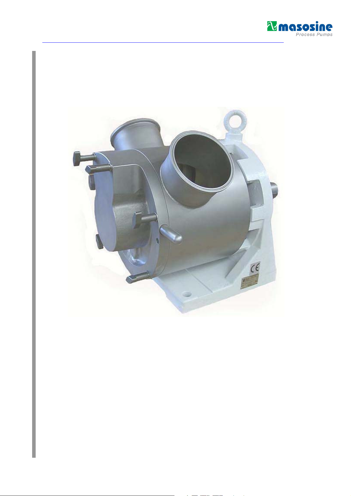
Manual – Technical Documentation
Watson-Marlow
MasoSine-PUMP
MR 160
N:\Konstruktion\Betriebsanleitungen\AKTUELL\MR Serie\TDE MR160.doc Revision 4 January 13
1
Page 2

Contents
Technical datasheet ..................................................................................................................................... 4
1 GENERAL ..................................................................................................................... 5
2 PURPOSE ..................................................................................................................... 5
3 FUNCTIONING PRINCIPLE .......................................................................................... 5
4 SAFETY INSTRUCTIONS ............................................................................................. 5
4.1 Basic safety instructions ...................................................................................................................... 5
4.2 Safety symbols .................................................................................................................................... 5
4.3 Obligation of the operator .................................................................................................................... 5
4.4 Organizational measures .................................................................................................................... 5
4.5 Obligation of the personnel ................................................................................................................. 6
4.6 Training of the personnel .................................................................................................................... 6
4.7 Informal safety measures .................................................................................................................... 6
4.8 Dangers when handling the machine .................................................................................................. 6
4.9 Safety measures in normal operation ................................................................................................. 6
4.10 Protective devices ............................................................................................................................... 6
4.11 Dangers due to hazardous pumped material ...................................................................................... 6
4.12 Dangers due to electrical energy ........................................................................................................ 6
4.13 Dangers due to hydraulic energy ........................................................................................................ 6
4.14 Special danger points .......................................................................................................................... 6
4.15 Constructional changes to the machine .............................................................................................. 7
4.16 Noise of the machine .......................................................................................................................... 7
4.17 Maintenance and repair, troubleshooting ............................................................................................ 7
4.18 Cleaning the machine ......................................................................................................................... 7
4.19 Faults ................................................................................................................................................... 7
4.20 Use as intended .................................................................................................................................. 7
5 WARRANTY AND LIABILITY ....................................................................................... 7
6 TRANSPORT INSTRUCTIONS ..................................................................................... 8
7 INSTALLATION............................................................................................................. 8
8 CONNECTION TO THE PIPING.................................................................................... 8
9 POSSIBLE CONNECTION POSITIONS ....................................................................... 9
10 CHANGING THE CONNECTION POSITION ............................................................. 9
11 CHANGING THE DIRECTION OF ROTATION .......................................................... 9
12 IMPORTANT: OBSERVE BEFORE START-UP! ..................................................... 10
13 RUNNING DRY......................................................................................................... 10
14 CLEANING ............................................................................................................... 10
14.1 Cleaning in own circuit with water, alkali, acid .................................................................................. 10
14.2 Cleaning in the CIP circuit ................................................................................................................. 11
14.3 Manual cleaning ................................................................................................................................ 11
14.4 Sterilization ........................................................................................................................................ 11
N:\Konstruktion\Betriebsanleitungen\AKTUELL\MR Serie\TDE MR160.doc Revision 4 January 13
2
Page 3

15 OIL CHANGE ........................................................................................................... 11
16 DISPOSAL ............................................................................................................... 12
17 SPARE PARTS ........................................................................................................ 12
18 TAKING OUT OF SERVICE ..................................................................................... 12
18.1 Provisional taking out of service ........................................................................................................ 12
18.2 Final putting out of service ................................................................................................................ 12
19 TROUBLESHOOTING ............................................................................................. 13
20 ADJUSTING DIMENSION ........................................................................................ 15
21 ASSEMBLY .............................................................................................................. 16
22 DRAWINGS / STOCK LISTS ................................................................................... 19
N:\Konstruktion\Betriebsanleitungen\AKTUELL\MR Serie\TDE MR160.doc Revision 4 January 13
3
Page 4

Technical datasheet
Please remove all technical information from the technical datasheet.
For spare parts ordering refer to software component list.
If you have problems to identify parts, please refer the drawing and parts list.
N:\Konstruktion\Betriebsanleitungen\AKTUELL\MR Serie\TDE MR160.doc Revision 4 January 13
4
Page 5
1 General
The operating instructions apply for the WATSON-MARLOW MasoSine-PUMPS :
MR 160
The operating instructions must be read before installing the pumps. Please observe the safety instructions and the safety regulations.
2 Purpose
The purpose is defined accurately in the order confirmation.
3 Functioning principle
The functioning principle of the WATSON-MARLOW MasoSine-PUMPS is ingeniously simple. The pump consists of modular
components. Because of the sinusoidal form of the Rotor, a chamber through which the product to be pumped is „pushed through“ or
displaced is created four times per revolution when running through the Stator space.
As soon as a chamber closes, the opposite chamber opens by the same fraction of a millimeter as the closing chamber is contracted.
A suction and pressure characteristic of the pump free of pulsation results. The Scraper prevents the pressure compensation of the
pressure to the suction side. At the same time the Scraper undertakes the important function of forced lubrication of the pump bearings,
or when the pump is cleaned the intensive purging of the bearing or of the seal.
4 Safety instructions
4.1 Basic safety instructions
A basic requirement for safe handling and troublefree operation of this machine is knowledge of the basic safety instructions and of the
safety regulations.
These operating instructions contain the most important instructions to operate the machine safely.
These operating instructions, especially the safety instructions, must be observed by all persons who work on the machine.
Moreover the rules and regulations for accident prevention applicable at the place of use must be complied with.
The following safety instructions must be observed absolutely.
They are an essential and indispensable part of the user documentation. Non-compliance can result in loss of warranty claims.
It is recommended in the interest of all involved to enter all installation measures, maintenance, fault and repair cases, training courses,
instructions and special occurrences in a logbook assigned to the machine.
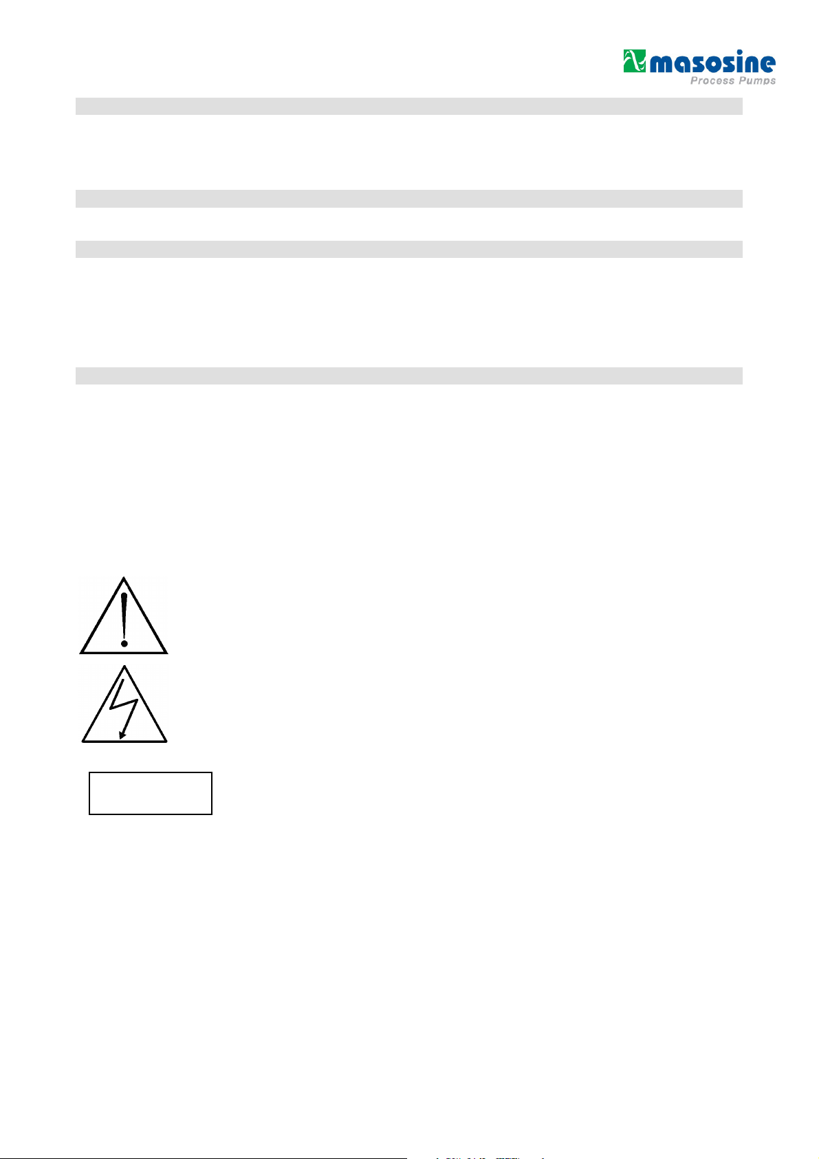
4.2 Safety symbols
CCAAUUTTIIOONN
Safety instruction which can cause danger for persons if not complied with
Safety instruction for electrical voltage
Safety instruction which can cause danger for the pump and is function if not complied with.
4.3 Obligation of the operator
The operator obligates itself to let only persons who are familiar with the basic regulations concerning working safety and accident
prevention and are instructed in handling the machine, as well as have read, understood and confirmed by their signature the warning
notes in these operating instructions to work on the machine.
The safety-conscious working of the personnel will be checked at regular intervals.
4.4 Organizational measures
The required personal protective equipment shall be provided by the operator.
All existing safety devices shall be checked regularly.
N:\Konstruktion\Betriebsanleitungen\AKTUELL\MR Serie\TDE MR160.doc Revision 4 January 13
5
Page 6

4.5 Obligation of the personnel
All persons who are authorized to work on the machine obligate themselves to observe the basic regulations concerning working safety
and accident prevention before starting work, to read the safety chapter and the warning notes in these operating instructions and to
confirm by their signature that they have understood these.
4.6 Training of the personnel
Only trained and instructed personnel may work on the machine. The responsibilities of the personnel shall be defined clearly for
assembly, start-up, operation, setting, maintaining and repairing.
Personnel under training may work on the machine only under supervision of an experienced person.
4.7 Informal safety measures
The operating instructions must be kept constantly at the place of use of the machine. The generally valid as well as the local
regulations for accident prevention and environmental protection shall be provided and observed in addition to the operating
instructions. All safety and danger warnings on the machine shall be kept in legible condition.
4.8 Dangers when handling the machine
The WATSON-MARLOW MasoSine-PUMPS is built according to the state of the art and the recognized safety engineering rules.
Nevertheless danger to life and limb of the user or third persons or impairments to the machine or to other assets can arise in its use.
The machine must be used only:
• for the intended use (see technical datasheet)
• in perfect safety engineering condition.
Faults which can impair safety must be rectified immediately.
4.9 Safety measures in normal operation
Operate the machine only if all protective devices are fully functioning. Before switching the machine on make sure that no one can be
endangered by the starting machine. At least once per shift inspect the machine for “externally detectable damage” and for functioning
of the safety devices.
4.10 Protective devices
All protective devices must be attached correctly and functioning before every start-up.
Protective devices may be removed only
- after standstill and simultaneous protection against restarting the machine.
On delivery of part components the protective devices must be attached according to regulations by the operator.
If hot or cold machine parts can lead to danger, these must be protected by the operator on site against contact.
4.11 Dangers due to hazardous pumped material
In the case of hazardous pumped material (according to ArbStoffV) the corresponding regulations must be complied with.
4.12 Dangers due to electrical energy
Have work on the electrical supply performed only by an electrician. Check the electrical equipment of the machine
regularly. Rectify loose connections and scorched cables immediately.
Keep the control cabinet closed always. Access is allowed only to authorized personnel with key or tool.
If work on parts conducting voltage is necessary, call in a second person who switches off the main switch if
necessary.
If you make the electrical connection of the pump, act according to DIN EN 60204!
Connect only by skilled personnel!
4.13 Dangers due to hydraulic energy
Only personnel with special knowledge and experience in hydraulics may work on hydraulic devices.
Relieve the pressure in system sections and pressure lines to be opened before starting repair work. Replace hydraulic hose lines at
appropriate intervals, even if no safety-relevant defects are detectable.
4.14 Special danger points
Rotating rotor in the pump. Danger of crushing or cutting off fingers and hands. The
pump must be protected by the customer so that it is not possible for persons to grasp in
the opening with the rotor running. In the case of work on the stationary Rotor, the drive
must be secured against unintentional switching on. Increased danger exists with
dismantled pipes and opened pump.
N:\Konstruktion\Betriebsanleitungen\AKTUELL\MR Serie\TDE MR160.doc Revision 4 January 13
6
Page 7

4.15 Constructional changes to the machine
Make no changes, attachments or conversions to the machine without approval of the manufacturer. All conversion measures require a
written confirmation of the MASO company. Immediately replace machine parts in not perfect condition. Use only original spare and
wearing parts. In the case of parts not obtained from MASO it is not guaranteed that they are designed and manufactured in compliance
with load and safety requirements.
4.16 Noise of the machine
The continuous sound pressure level proceeding from the machine is max. 70 dB(A). A higher sound pressure level that causes noise
deafness can arise depending upon the local conditions. In this case protect the operating personnel with corresponding protective
equipment / protective measures.
4.17 Maintenance and repair, troubleshooting
Perform specified adjustment, maintenance and inspection work on time. Inform operating personnel before starting the maintenance
and repair work. Protect all plant parts and operating media connected before and after the machine such as compressed air and
hydraulics and similar against unintentional start-up. In all maintenance, inspection and repair work switch the machine free of voltage
and secure the main switch against unexpected switching back on. Fasten and secure larger assemblies on
replacement carefully to lifting gear. Check loosened screw connections for firm seating. Use only original spare parts.
After ending the maintenance work check the safety devices for function.
4.18 Cleaning the machine
Handle substances and materials used correctly, especially
- when working on lubricating systems
- when cleaning with solvents.
4.19 Faults
In the case of operating faults switch off the machine and secure it against unauthorized or inadvertent starting up again.
4.20 Use as intended
The accurate intention is listed in the order confirmation. Another use or use going beyond this is not as intended.
If you want to change the product, the pressure, the speed or the temperature, you must firstly consult us or one of our representatives.
5 Warranty and liability
Basically our “General sales and delivery conditions” apply.
These are available to the operator at the latest since conclusion of the contract.
Warranty and liability claims for personal and material damage are excluded if they are attributable to one or several of the following
causes:
• Use of the machine not as intended
• Incorrect installation, operation and maintenance of the machine
• Operating the machine with defective safety devices or not correctly attached or not functioning safety and protective devices
• Non-compliance with the instructions in the operating instructions regarding
• Unauthorized constructional changes to the machine
• Insufficient monitoring of machine parts subject to wear
• Incorrectly performed repairs
• Cases of catastrophe due to effect of foreign bodies and acts of God.
WATSON-MARLOW GmbH grants no warranty on this documentation as well as no implicit warranties on commercially customary
quality and suitability for a certain application.
WATSON-MARLOW GmbH undertakes no liability for errors contained in it or consequential damage occurring by chance arising due
to the design, performance and the use of this documentation.
This publication contains own information protected by copyright. All rights are reserved.
This publication may be neither photocopied, nor duplicated nor translated without previous agreement of WATSON-MARLOW GmbH .
Rights reserved to make changes in these operating instructions.
transport,
storage,
installation,
start-up,
operation, maintenance and setting of the machine.
N:\Konstruktion\Betriebsanleitungen\AKTUELL\MR Serie\TDE MR160.doc Revision 4 January 13
7
Page 8

6 Transport instructions
CCAAUUTTIIOONN
CCAAUUTTIIOONN
CCAAUUTTIIOONN
CCAAUUTTIIOONN
DO NOT START WITHOUT
CCAAUUTTIIOONN
CCAAUUTTIIOONN
CCAAUUTTIIOONN
The choice of the means of transport is according to the size of the pump and of the drive. The pump must be suspended correctly for
transport. The crane/forklift truck and the ropes/belts must be sufficiently dimensioned. If the pump is transported with a lift truck or a
forklift truck, it must be noted that the console centre point is not automatically the centre of gravity.
wrong right
7
Installation
The motor shaft and pump shaft
connection must be protected against
contact!
Place the pump on a level ground.
Do not start without the protection against contact!!
The foundation should be dimensioned sufficiently for the weight of the pump.
There should be sufficient space for maintenance work around the pump.
It must be guaranteed that the motor receives an adequate air supply.
If the pump is used in explosion endangered rooms, an Ex protected motor must be used.
The total unit must be protected against static charge.
wrong
PROTECTION AGAINST CONTACT!!
.
Align the shaft of the pump with the shaft of the drive.
8 Connection to the piping
Before connection clean the piping and remove foreign bodies.
(e.g. there can still be residues in the pipes due to welding work).
Fit elastic intermediate members (compensators) between pump and fixed piping on the suction
and pressure side. This should prevent vibrations of the pump being transmitted to the piping
system.
Forces and torques acting from the piping on the pump connections (e.g. due to distortion, expansion due
to temperatures etc.) must be avoided.
The pressure line should point upwards, so that later residual liquid can always flow back into the pump.
Thus total dry running is avoided. Further it facilitates the later suction process.
The operator has to ensure that an inadmissible pressure rise (above the pressure agreed in the order and
listed in the technical data) is not possible.
The operator has to ensure that the pump can work free of cavitation.
Cavitation destroys the pump
N:\Konstruktion\Betriebsanleitungen\AKTUELL\MR Serie\TDE MR160.doc Revision 4 January 13
8
Page 9

9 Possible connection positions
Let the change of direction of rotation on the drive be made only be trained skilled
When the connection position is changed, the motor must be protected against
Counterclockwise rotation of the rotor and motor Clockwise rotation of the rotor and motor
Unless otherwise ordered, the pump is delivered in position B
10 Changing the connection position
Remove the screws on the bearing block. Turn the housing by an angle of 45° to the left or right.
Tighten the screws again. (45 Nm)
However, take care that due to the corresponding arrangement of the pressure line in the pump, a certain
residual amount remains. By this measure you make it easier for the pump to draw in highly viscous products.
However, in the case of horizontally lying pressure connection you must absolutely take care that the pressure
line is run so that the pump is always covered with residual liquid. In this way total dry running is avoided.
unintentional switching on!!
11 Changing the direction of rotation
personnel. The motor must be protected against unintentional switching on!
The suction or the pressure side changes on
changing the direction of rotation of the drive.
Then the Scraper and the Scraper gate guide
must absolutely be turned, since otherwise the
pump cannot bring its full output. If the direction of
rotation is changed, the rotation direction arrows
must be turned correspondingly. Further the
suction or pressure connection must be marked.
The set direction of rotation is stated by an arrow.
The pump can run against the set direction only
for a short time. It cannot build up more than 2
bar pressure if the direction of rotation is wrong.
N:\Konstruktion\Betriebsanleitungen\AKTUELL\MR Serie\TDE MR160.doc Revision 4 January 13
9
Page 10

12 Important: Observe before start-up!
CCAAUUTTIIOONN
CCAAUUTTIIOONN
CCAAUUTTIIOONN
CCAAUUTTIIOONN
If you have performed cleaning or repair work or make the first start-up, check before start-up that all screws are correctly and
completely tightened.
The pressure line should point upwards so that residual liquid can always flow back into the pump later. This avoids total dry running.
Further it facilitates the later suction process.
The pump can possibly be contaminated by transport, therefore remove the pump cover and clean if necessary before start-up.
Before you start up the pump, convince yourself once again that the Scraper and the Scraper gate guide are in the correct position in
relation to the pressure side (see change of direction of rotation).
Connect the purging
Observe the corresponding regulations in the case of hazardous pumped material (according to ArbStoffV).
Before the first start-up fill with water or pumped material to avoid dry running and to facilitate the suction
CCAAUUTTIIOONN
CCAAUUTTIIOONN
process.
The pump is proof against dry running only as long as the heat resistance of the seals is guaranteed. This is
approx. 1 minute under the most unfavourable conditions – as with maximum speed.
The motor must be connected by an expert according to DIN EN 60204.
Make sure before start-up that all valves on the pressure and suction side are open. The pump may not
pump against a closed valve without overpressure valve.
If the pump leaks, end operation as quickly as possible to replace the damaged sealing elements.
The operator must ensure that the pump can work free of cavitation.
Cavitation destroys the pump.
13 Running dry
The pump is proof against running dry only as long as the heat resistance of the seals is guaranteed. This is approx. 1 minute under
most unfavourable circumstances – such as at maximum speed.
If you have a pump with a Mechanical Seal System:
A pump with a Mechanical Seal may never run dry!
Purging should be without pressure, this means that the purging water runs out from the purging system without pressure (thumb test: it
must be possible to stop water with the thumb).
14 Cleaning
All WATSON-MARLOW MasoSine-PUMPS are fully capable of CIP cleaning. Please observe our CIP cleaning regulations.
14.1 Cleaning in own circuit with water, alkali, acid
1. Set control gear to maximum speed (at least 400 rpm).
2. Choke after the pump so that a counterpressure of 3 to 4 bar arises.
3. Should the required cleaning effect not be achieved after this process,
it is necessary to dismantle the pump.
This is done in a few minutes as described in detail in the operating instructions.
Manual cleaning of the pump can be performed after complete dismantling of the pump.
Pay attention to parts sensitive to breakage!!
N:\Konstruktion\Betriebsanleitungen\AKTUELL\MR Serie\TDE MR160.doc Revision 4 January 13
10
Page 11

14.2 Cleaning in the CIP circuit
X + 3 bar
Open / Close Valve
X -
bar
Oil inlet
Back to the plant
Choke
1. Purging surge
Open the choke valve and let the WATSON-MARLOW MasoSinePUMPS run with maximum speed to perform the first rough cleaning.
2. Purging
Set the choke valve so that the pressure side of the pump is at least
3.0 bar higher than the suction side.
Open the open/close valve to guarantee cleaning of the series
connected devices.
from CIP plant
14.3 Manual cleaning
Manual cleaning of the pump can be performed after complete dismantling of the pump.
Pay attention to parts sensitive to breakage!!
If the pump is stopped during the process and opened for the purpose of cleaning or checking,
the responsible fitter or electrician must be notified to undertake suitable measures so that the pump
cannot be put into operation (remove fuses, notify electrician).
The pump may also never be put into operation if the housing cover is removed. Should the pump
not yet be connected to the piping system, then reliable care must be taken that the drive machine
cannot be switched on.
Observe the accident prevention regulations!!
14.4 Sterilization
Sterilisation of the pump with standard equipment is possible up to 110°C only in standstill!
In the case of special equipment of the pump or higher temperatures, please always firstly consult the manufacturer!
15 Oil change
The oil must be changed once yearly or every 1500 operating hours for
the pumps of the serie MR 160. The standard operation for changing oil
would be to loosen all four bolts on the bearing housing cover (Pos. 21)
and all parts should be removed (bolts and cover). At this point the used
oil can be drained. After that the bearing housing cover has to be
replaced and the bolts would be retighten. The oil sight glass in the
bearing block should be filled up to the middle. (ca 0.3 Liter). Please use
the following oil grade or similar:
***(Standard first filling of the WATSON-MARLOW MasoSine-
Klüberoil 4 UH 1-220 N (lubricating oil for the food and pharmaceutical
industry)
PUMPS)***
Oil glass
Our standard first filling is only suitable for
temperatures above –10° C.
If you come below –10° C you must replace the oil !
N:\Konstruktion\Betriebsanleitungen\AKTUELL\MR Serie\TDE MR160.doc Revision 4 January 13
11
Page 12

16 Disposal
Send the old oil for treatment.
17 Spare parts
Basically repairs should be performed only by factory personnel or by customer service agencies authorized by the factory. If you make
repairs yourself, observe the relevant safety regulations and contact the factory customer service before starting the work, especially if
warranty obligations which can be lost by not approved repairs still exist.
Only WATSON-MARLOW-ORIGINAL-SPARE-PARTS may be used.
If you make changes to the equipment, e.g. instead of O-rings made of Perbunan
those from EPDM, or another sealing system, please note this on the maintenance
plan.
Please provide all data when ordering:
- EDP number - Designation of the part
- Material of the part - The drawing / parts list number
- Quantity - Ask for our express delivery!
MASO PROCESS-PUMPEN GmbH
WATSON-MARLOW GmbH
Postfach 100
Postfach 100
STEINBEISSTR. 3
STEINBEISSTR. 3
D-74358 ILSFELD (GERMANY)
D-74358 ILSFELD (GERMANY)
TELEFON : (07062) 9560-0
TELEPHON : +49 7062 9560-0
TELEFAX : (07062) 64593
TELEFAX : +49 7062 64593
EMail Info@maso.de
EMail Info@masosine.de
Internet http://www.maso.de
Internet http://www.masosine.de
18 Taking out of service
18.1 Provisional taking out of service
Short term:
Remove product residues (cleaning) Switch off main switch Clean pump surface
Longer term:
Remove product residues carefully (cleaning ) Switch off main switch Clean pump surface Disconnect connections
Drain off static purging liquid Loosen purging connections Store the scraper in water.
18.2 Final putting out of service
Separate power and purging liquid supply. Send oils and greases for treatment.
If you send us the remaining parts freight paid, we will dispose of the parts.
N:\Konstruktion\Betriebsanleitungen\AKTUELL\MR Serie\TDE MR160.doc Revision 4 January 13
12
Page 13

19 Troubleshooting
Error Cause Remedy
Pump does not draw in
Pump does not deliver
Pump is noisy
Pump leaking at leakage
hole
Pump leaking at the front
housing
Direction of rotation not correct Check direction of rotation
No wetting liquid in the pump Fill pump with liquid
Screw fastening not tight Check screw fastening
Suction pipe too long Adapt suction pipe
Pipe cross-section too narrow Adapt suction pipe
Shaft seal leaking Check all seals for damage
Wear in the pump Change wearing parts
Motor speed not correct Measure, regulate speed
Scraper and cartridge wrongly
inserted
Direction of rotation not correct Check direction of rotation
Suction and pressure pipe
confused
Motor speed not correct Check speed based on output
Wearing parts worn Replace wearing parts
Scraper and cartridge wrong Check position (see changing
Inserted closed gate valve Check pipe system
Noises come from the drive Consult WATSON-MARLOW
Noises come from the pump Consult WATSON-MARLOW
Suction pipe too small (cavitation) Shorten suction pipe or increase
Knocking noises from the pump
head
Noises from bearing block Fill oil, change tapered roller
Coupling not aligned Align coupling with hairline
Shaft seal leaking Change GLRD or radial shaft
O-ring seal leaking Replace O-ring
Radial shaft sealing ring on the
bearing block leaking, oil escapes
Housing seal not or wrongly
installed
Housing seal defective Install housing O-ring correctly or
Check position (see changing
direction of rotation)
Check pipe system
diagrams
direction of rotation)
diameter, reduce speed
Gate valve wear
bearings
sealing rings
Dismantle bearing block,
replace radial shaft sealing rings
Install housing O-ring correctly or
replace
replace
N:\Konstruktion\Betriebsanleitungen\AKTUELL\MR Serie\TDE MR160.doc Revision 4 January 13
13
Page 14

Error Cause Remedy
Pump has blocked
Strong wear after short
operating time
Rotor has wear on one side
Pump not clean after CIP
cleaning
Rotor has seized on Liners
Purging between housing
and bearing block leaking
Water or pumped material
in the bearing block
Front bearing has seized on
rotor
Foreign body in the pump Remove foreign body, examine
pump for damage
Power supply interrupted Check electrical installations
(fuses), check drive
Defect on the drive (Separate the coupling and turn
the pump by hand)
Solids in the pumped material
Pumped material is abrasive
Rotor not tightened correctly on
installation
Adjusting dimensions changed after
working on the bearing block
Cleaning regulation not complied
with
Rotor not correctly tightened Tighten closing nut firmly on
Temperature too high
(thermal expansion)
O-ring in the bearing block missing
or defective
Purging pressure too high Purging must be pressureless
Leakage bores closed Check leakage bores for free
O-ring in the front bearing missing
or worn
Front bearing wrongly installed Examine front bearing for
Frequent change of the wearing
parts, change material pairing
Choose larger pump,
reduce speed
Tighten closing nut firmly on
block
Check and correct the adjusting
dimensions
MR 160 = 35.6mm +0.1
Choke on the pressure side
Check differential pressure 3-4
bar
block
Choose Liners with larger
tolerances
Install or replace O-ring
(attach pressure reducer, max.
0.1 bar)
passage, replace shaft seals on
pump and bearing block
Install or replace O-ring
damage and install in correct
position
N:\Konstruktion\Betriebsanleitungen\AKTUELL\MR Serie\TDE MR160.doc Revision 4 January 13
14
Page 15

20 Adjusting dimension
The Adjusting dimension will be measured at point X 35.6mm +0.1 (see diagnostic help page 14)
If the dimension is too small, you have to turn the Adjusting ring.
If the dimension is too big, please contact the company WATSON-MARLOW MasoSine and order a new
Adjusting ring.
Adjusting ring
N:\Konstruktion\Betriebsanleitungen\AKTUELL\MR Serie\TDE MR160.doc Revision 4 January 13
15
Page 16

21 Assembly
Radial shaft seal Pos 32
Radial shaft seal Pos
Backing ring Pos 6
The pin has to be fixed in the groove in the pump
housing
The seal housing push up to notice
N:\Konstruktion\Betriebsanleitungen\AKTUELL\MR Serie\TDE MR160.doc Revision 4 January 13
16
Page 17

During the right
run the scraper
gate guide and
Scraper have to
be turned!
See page 9
chapters 11
“changing the
direction of
rotating”
Install the Scraper gate guide,
Scraper and Rotor as a unit
tighten the locking nut with the torque of 160 Nm
The pin of the front bearing has to be fixed of the
groove in the front cover
N:\Konstruktion\Betriebsanleitungen\AKTUELL\MR Serie\TDE MR160.doc Revision 4 January 13
17
Page 18

18
Take care during all works that the O-rings will be
assembled completely and without any damage.
If you have questions, call us. We will happy to help.
WATSON-MARLOW GmbH
Postfach 100
STEINBEISSTR. 3
D-74358 ILSFELD (GERMANY)
Telefon (07062) 9560-0
Telefax (07062) 64593
eMail Info@masosine.de
Internet http://www.masosine.de
N:\Konstruktion\Betriebsanleitungen\AKTUELL\MR Serie\TDE MR160.doc Revision 4 January 13
Page 19

19
22 Drawings / Stock lists
N:\Konstruktion\Betriebsanleitungen\AKTUELL\MR Serie\TDE MR160.doc Revision 4 January 13
Page 20

20
N:\Konstruktion\Betriebsanleitungen\AKTUELL\MR Serie\TDE MR160.doc Revision 4 January 13
Page 21

21
N:\Konstruktion\Betriebsanleitungen\AKTUELL\MR Serie\TDE MR160.doc Revision 4 January 13
Page 22

22
N:\Konstruktion\Betriebsanleitungen\AKTUELL\MR Serie\TDE MR160.doc Revision 4 January 13
Page 23

23
N:\Konstruktion\Betriebsanleitungen\AKTUELL\MR Serie\TDE MR160.doc Revision 4 January 13
Page 24

24
N:\Konstruktion\Betriebsanleitungen\AKTUELL\MR Serie\TDE MR160.doc Revision 4 January 13
 Loading...