

Page 1
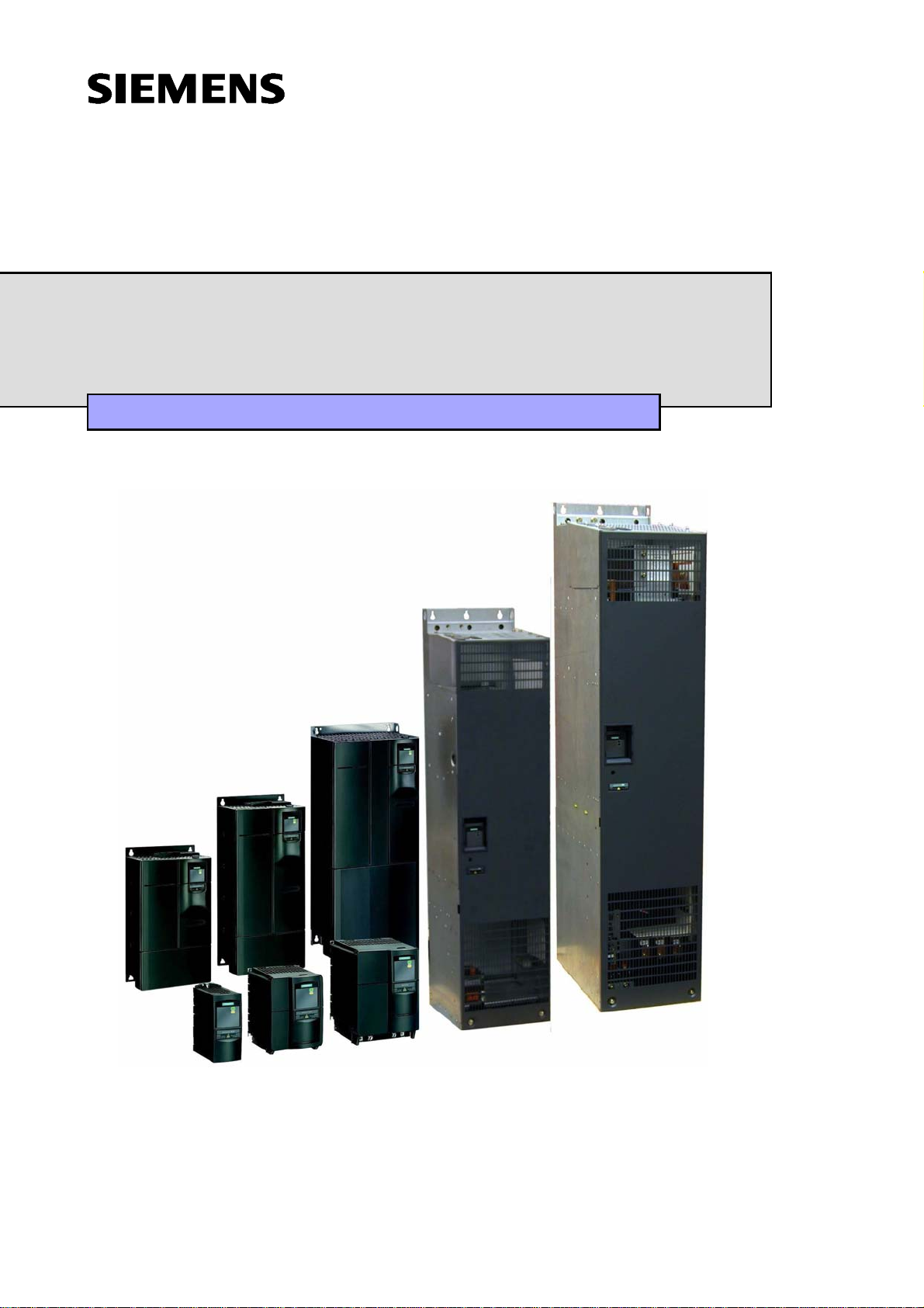
MICROMASTER 440
0.12 kW - 250 kW
Operating Instructions Issue 10/06
User Documentation
6SE6400-5AW00-0BP0
Page 2
MICROMASTER 440 Documentation
Getting Started Guide
Is for quick commissioning with SDP and BOP.
Operating Instructions
Gives information about features of the
MICROMASTER 440, Installation, Commissioning,
Control modes, System Parameter structure,
Troubleshooting, Specifications and available options
of the MICROMASTER 440.
Parameter List
The Parameter List contains the description of all
Parameters structured in functional order and a
detailed description. The Parameter list also includes
a series of function plans.
Catalogues
In the catalogue you will find all the necessary
information to select an appropriate inverter, as well
as filters, chokes, operator panels and
communication options.
Page 3

Overview
1
MICROMASTER 440
0.12 kW - 250 kW
Operating Instructions
User Documentation
Installation
Functions
Troubleshooting
Specifications
Options
Electro-Magnetic
Compatibility
2
3
4
5
6
7
Valid for Issue 10/06
Inverter Type Software Version
MICROMASTER 440 2.1
0.12 kW - 250 kW
Appendices
Index
A
B
C
D
E
F
G
Issue 10/06
Page 4

Further information can be obtained from Internet
website:
http://www.siemens.de/micromaster
Approved Siemens Quality for Software and Training
is to DIN ISO 9001, Reg. No. 2160-01
The reproduction, transmission or use of this document,
or its contents is not permitted unless authorized in
writing. Offenders will be liable for damages. All rights
including rights created by patent grant or registration of a
utility model or design are reserved.
© Siemens AG 2001 – 2005, 2006. All Rights Reserved.
MICROMASTER® is a registered trademark of Siemens
Order number: 6SE6400-5AW00-0BP0
Other functions not described in this document may be
available. However, this fact shall not constitute an
obligation to supply such functions with a new control, or
when servicing.
We have checked that the contents of this document
correspond to the hardware and software described.
There may be discrepancies nevertheless, and no
guarantee can be given that they are completely identical.
The information contained in this document is reviewed
regularly and any necessary changes will be included in
the next edition. We welcome suggestions for
improvement.
Siemens handbooks are printed on chlorine-free paper
that has been produced from managed sustainable
forests. No solvents have been used in the printing or
binding process.
Document subject to change without prior notice.
Siemens-Aktiengesellschaft
MICROMASTER 440 Operating Instructions
4 6SE6400-5AW00-0BP0
Page 5

Issue 10/06 Foreword
Foreword
User Documentation
WARNING
Before installing and commissioning the inverter, you must read all safety
instructions and warnings carefully including all the warning labels attached to the
equipment. Make sure that the warning labels are kept in a legible condition and
replace missing or damaged labels.
Information is also available from:
Regional Contacts
Please get in touch with your contact for Technical Support in your Region for
questions about services, prices and conditions of Technical Support.
Central Technical Support
The competent consulting service for technical issues with a broad range of
requirements-based services around our products and systems.
Europe / Africa
Tel: +49 (0) 180 5050 222
Fax: +49 (0) 180 5050 223
Email: adsupport@siemens.com
America
Tel: +1 423 262 2522
Fax: +1 423 262 2589
Email: simatic.hotline@sea.siemens.com
Asia / Pazific
Tel: +86 1064 757 575
Fax: +86 1064 747 474
Email: adsupport.asia@siemens.com
Online Service & Support
The comprehensive, generally available information system over the Internet, from
product support to service & support to the support tools in the shop.
http://www.siemens.com/automation/service&support
Contact address
Should any questions or problems arise while reading this manual, please contact
the Siemens office concerned using the form provided at the back this manual.
MICROMASTER 440 Operating Instructions
6SE6400-5AW00-0BP0
5
Page 6
Definitions and Warnings Issue 10/06
Definitions and Warnings
DANGER
indicates an immanently hazardous situation which, if not avoided, will result in
death or serious injury.
WARNING
indicates a potentially hazardous situation which, if not avoided, could result in
death or serious injury.
CAUTION
used with the safety alert symbol indicates a potentially hazardous situation
which, if not avoided, may result in minor or moderate injury.
PE
= Ground
CAUTION
used without safety alert symbol indicates a potentially hazardous situation which,
if not avoided, may result in a property damage.
NOTICE
indicates a potential situation which, if not avoided, may result in an undesirable
result or state.
NOTE
For the purpose of this documentation, "Note" indicates important information
relating to the product or highlights part of the documentation for special
attention.
Qualified personnel
For the purpose of this Instruction Manual and product labels, a "Qualified
person" is someone who is familiar with the installation, mounting, start-up and
operation of the equipment and the hazards involved.
He or she must have the following qualifications:
1. Trained and authorized to energize, de-energize, clear, gro und and tag circuits
and equipment in accordance with established safety procedures.
2. Trained in the proper care and u se of protective equipment in accordance with
established safety procedures.
3. Trained in rendering first aid.
♦ PE – Protective Earth uses circuit protective conductors sized for short circuits
where the voltage will not rise in excess of 50 Volts. This connection is
normally used to ground the inverter.
♦
- Is the ground connection where the reference voltage can be the same as
the Earth voltage. This connection is normally used to ground the motor.
Use for intended purpose only
The equipment may be used only for the application stated in the manual and only
in conjunction with devices and components recommended and authorized by
Siemens.
MICROMASTER 440 Operating Instructions
6 6SE6400-5AW00-0BP0
Page 7

Issue 10/06 Safety Instructions
Safety Instructions
The following Warnings, Cautions and Notes are provided for your safety and as a
means of preventing damage to the product or components in the machines
connected. This section lists Warnings, Cautions and Notes, which apply generally
when handling MICROMASTER 440 Inverters, classified as General, Transport &
Storage, Commissioning, Operation, Repair and Dismantling & Disposal.
Specific Warnings, Cautions and Notes that apply to particular activities are
listed at the beginning of the relevant chapters and are repeated or supplemented
at critical points throughout these sections.
Please read the information carefully, since it is provided for your personal
safety and will also help prolong the service life of your MICROMASTER 440
Inverter and the equipment you connect to it.
General
WARNING
¾ This equipment contains dangerous voltages and controls potentially
dangerous rotating mechanical parts. Non-compliance with Warnings or
failure to follow the instructions contained in this manual can result in loss of
life, severe personal injury or serious damage to property.
¾ Only suitable qualified personnel should work on this equipment, and only after
becoming familiar with all safety notices, installation, operation and
maintenance procedures contained in this manual. The successful and safe
operation of this equipment is dependent upon its proper handling, installation,
operation and maintenance.
¾ Risk of electric shock. The DC link capacitors remain charged for five minutes
after power has been removed. It is not permissible to open the equipment
until 5 minutes after the power has been removed.
The following terminals can carry dangerous voltages even if the inverter is
inoperative:
♦ the power supply L/L1, N/L2, L3 resp. U1/L1, V1/L2, W1/L3
♦ the motor terminals U, V, W resp. U2, V2, W2
♦ and depending on the frame size the terminals DC+/B+, DC-, B-, DC/R+
resp. DCPS, DCNS, DCPA, DCNA
¾ HP ratings are based o n the Siemens 1LA motors and are given for
guidance only; they do not necessarily comply with UL or NEMA HP
ratings.
CAUTION
¾ Children and the general public must be prevented from accessing or
approaching the equipment!
¾ This equipment may only be use d for the purpose specified by the
manufacturer. Unauthorized modifications and the use of spare parts and
accessories that are not sold or recommended by the manufacturer of the
equipment can cause fires, electric shocks and injuries.
MICROMASTER 440 Operating Instructions
6SE6400-5AW00-0BP0
7
Page 8

Safety Instructions Issue 10/06
NOTICE
¾ Keep these operating instructions within easy reach of the equipment and
make them available to all users
¾ Whenever measuring or testing has to be performed on live equipment, the
regulations of Safety Code BGV A2 must be observed, in particular §8
“Permissible Deviations when Working on Live Parts”. Suitable electronic tools
should be used.
¾ Before installing and commissioning, please read these safety instructions and
warnings carefully and all the warning labels attached to the equipment. Make
sure that the warning labels are kept in a legible condition and replace missing
or damaged labels.
Transport & Storage
WARNING
Correct transport, storage, erection and mounting, as well as careful operation
and maintenance are essential for proper and safe operation of the equipment.
CAUTION
Protect the inverter against physical shocks and vibration during transport and
storage. Also be sure to protect it against water (rainfall) and excessive
temperatures (see Table 4-1).
Commissioning
WARNING
¾ Work on the device/system by unqualified personnel or failure to comply with
warnings can result in severe personal injury or serious damage to material.
Only suitably qualified personnel trained in the setup, installation,
commissioning and operation of the product should carry out work on the
device/system.
¾ Only permanently-wired input power connections are allowed. This equipment
must be grounded (IEC 536 Class 1, NEC and other applicable standards).
¾ Only type B ELCBs should be used with FSA to FSF. Machines with a three-
phase power supply, fitted with EMC filters, must not be connected to a supply
via an ELCB (Earth Leakage Circuit-Breaker - see DIN VDE 0160, section
5.5.2 and EN50178 section 5.2.11.1).
¾ The following terminals can carry dangerous voltages even if the inverter is
inoperative:
♦ the power supply L/L1, N/L2, L3 resp. U1/L1, V1/L2, W1/L3
♦ the motor terminals U, V, W resp. U2, V2, W2
♦ and depending on the frame size the terminals DC+/B+, DC-, B-, DC/R+
resp. DCPS, DCNS, DCPA, DCNA
¾ This equipment must not b e used as an ‘emergency stop mechanism’ (see EN
60204, 9.2.5.4)
CAUTION
The connection of power, motor and control cables to the inverter must be carried
out as shown in Fig. 2-11 on page 44, to prevent inductive and capacitive
interference from affecting the correct functioning of the inverter.
MICROMASTER 440 Operating Instructions
8 6SE6400-5AW00-0BP0
Page 9

Issue 10/06 Safety Instructions
Operation
WARNING
¾ MICROMASTERS operate at high voltages.
¾ When operating ele ctrical device s, it is impossibl e to avoid applying
hazardous voltages to certain parts of the equipment.
¾ Emergency Stop facilities according to EN 60204 IEC 204 (VDE 0113) must
remain operative in all operating modes of the control equipment. Any
disengagement of the Emergency Stop facility must not lead to uncontrolled or
undefined restart.
Certain parameter settings may cause the inverter to restart automatically
after an input power failure (e.g. automatic restart).
¾ Wherever faults occu rring in the control equipment can lead to substantial
material damage or even grievous bodily injury (i.e. potentially dangerous
faults), additional external precautions must be taken or facilities provided to
ensure or enforce safe operation, even when a fault occurs (e.g. independent
limit switches, mechanical interlocks, etc.).
¾ Motor parameters must be accurately configured for motor overload protection
to operate correctly.
¾ This equipment is cap able of providing internal motor overload protection in
accordance with UL508C section 42. Refer to P0610 and P0335, i
2
t is ON by
default. Motor overload protection can also be provided using an external PTC
or KTY84.
¾ This equipment is suitable for use in a circuit capable of delivering not more
than 10,000 (Frame Sizes A to C) or 42,000 (Frame Sizes D to GX)
symmetrical amperes (rms), for a maximum voltage of 230 V / 460 V / 575 V
when protected by an H, J or K type fuse, a circuit breaker or self-protected
combination motor controller (for more details see Appendix F).
¾ This equipment must not b e used as an ‘emergency stop mechanism’ (see EN
60204, 9.2.5.4)
Repair
WARNING
¾ Repairs on equipment may only be carried out by Siemens Serv ice, by repair
centers authorized by Siemens or by authorized personnel who are
thoroughly acquainted with all the warnings and operating procedures
contained in this manual.
¾ Any defective parts or compone nts must be replaced using parts contained in
the relevant spare parts list.
¾ Disconnect the power supply before opening the equipment for access.
Dismantling & Disposal
CAUTION
¾ The inverter’s packaging is re-usable. Re tain the packaging for future use.
¾ Easy-to-release screw and snap connectors allow you to break the unit down
into its component parts. You can then re-cycle these component parts,
dispose of them in accordance with local requirements or return them to
the manufacturer.
MICROMASTER 440 Operating Instructions
6SE6400-5AW00-0BP0
9
Page 10
Electrostatic Sensitive Devices (ESD) Issue 10/06
Electrostatic Sensitive Devices (ESD)
The device contains components which can be destroyed by electrostatic
discharge. These components can be easily destroyed if not carefully handled.
Before opening the cabinet/enclosure in which the device is located, you must
electrically discharge your body and apply the appropriate ESDS protective
measures. The cabinet/enclosure should be appropriately labeled.
If you have to handle electronic boards, please observe the following:
• Electronic boards should only be touched when absolutely nece s sary.
• The human body must be electrically discharged before touching an electronic
board.
• Boards must not come into contact with highly insulating materials - e.g. plastic
parts, insulated desktops, articles of clothing manufactured from man-made
fibers.
• Boards must only be placed on conductive surfaces.
• Boards and components should only be stored and transported in conductive
packaging (e.g. metalized plastic boxes or metal containers).
• If the packing material is not conductive, the boards must be wrapped with a
conductive packaging material, e.g. conductive foam rubber or household
aluminium foil.
The necessary ESD protective measures are clearly shown again in the following
diagram:
• a = Conductive floor surface
• b = ESD table
• c = ESD shoes
b
c
a
d
e
f
Sitting
f f f
c
Standing Standing / Sitting
• d = ESD overall
• e = ESD chain
• f = Cubicle ground connection
d
f
a
b
c
d
e
a
MICROMASTER 440 Operating Instructions
10 6SE6400-5AW00-0BP0
Page 11

Issue 10/06 Table of Contents
Table of Contents
1 Overview................................................................................................................17
1.1 The MICROMASTER 440....................................................................................... 18
1.2 Features.................................................................................................................. 19
2 Installation............................................................................................................. 21
2.1 Installation after a Period of Storage...................................................................... 23
2.2 Ambient operating conditions ................................................................................. 24
2.3 Mechanical installation............................................................................................ 26
2.4 Electrical installation ............................................................................................... 33
3 Functions............................................................................................................... 47
3.1 Parameters ............................................................................................................. 51
3.2 Operator panels for MICROMASTER..................................................................... 70
3.3 Block diagram......................................................................................................... 74
3.4 Factory setting ........................................................................................................ 75
3.5 Commissioning ....................................................................................................... 77
3.6 Inputs / outputs ..................................................................................................... 135
3.7 Communications...................................................................................................144
3.8 Fixed frequencies (FF).......................................................................................... 167
3.9 Motorized potentiometer (MOP) ........................................................................... 170
3.10 JOG....................................................................................................................... 172
3.11 PID controller (technological controller)................................................................ 173
3.12 Setpoint channel...................................................................................................181
3.13 Free function blocks (FFB) ................................................................................... 191
3.14 Motor holding brake (MHB)................................................................................... 196
3.15 Electronic brakes .................................................................................................. 202
3.16 Automatic restart................................................................................................... 211
3.17 Flying restart.........................................................................................................213
3.18 Closed-loop Vdc control........................................................................................ 215
3.19 Positioning down ramp ......................................................................................... 219
3.20 Monitoring functions / messages.......................................................................... 221
3.21 Thermal motor protection and overload responses.............................................. 227
3.22 Power module protection...................................................................................... 232
3.23 Open-loop/closed-loop control technique.............................................................235
4 Troubleshooting.................................................................................................. 257
4.1 Troubleshooting with the SDP.............................................................................. 258
4.2 Troubleshooting with the BOP.............................................................................. 259
MICROMASTER 440 Operating Instructions
6SE6400-5AW00-0BP0
11
Page 12

Table of Contents Issue 10/06
4.3 Fault messages..................................................................................................... 260
4.4 Alarm Messages...................................................................................................260
5 MICROMASTER 440 specifications................................................................... 261
6 Options ................................................................................................................ 273
6.1 Inverter-independent options................................................................................ 273
6.2 Inverter-dependent options................................................................................... 274
7 Electro-magnetic compatibility (EMC).............................................................. 275
7.1 Electro-magnetic compatibility..............................................................................276
Appendices..............................................................................................................................281
A Changing the Operator Panel............................................................................ 281
B Removing Front Covers..................................................................................... 282
B.1 Removing Front Covers. Frame Sizes A..............................................................282
B.2 Removing Front Covers. Frame Sizes B and C ................................................... 283
B.3 Removing Front Covers. Frame Sizes D and E ................................................... 284
B.4 Removing Front Covers. Frame Size F................................................................285
B.5 Removing Front Covers. Frame Sizes FX and GX.............................................. 286
C Removing the I/O Board..................................................................................... 287
D Removing ‘Y’ Cap ............................................................................................... 288
D.1 Removing ‘Y’ Cap. Frame Size A......................................................................... 288
D.2 Removing ‘Y’ Cap. Frame Sizes B and C............................................................. 289
D.3 Removing ‘Y’ Cap. Frame Sizes D and E............................................................. 290
D.4 Removing ‘Y’ Cap. Frame Size F......................................................................... 291
D.5 Removing ‘Y’ Cap. Frame Size FX....................................................................... 292
D.6 Removing ‘Y’ Cap. Frame Size GX......................................................................293
E Removing fan ...................................................................................................... 294
E.1 Removing fan. Frame Size A................................................................................ 294
E.2 Removing fan. Frame Sizes B and C ................................................................... 295
E.3 Removing fan. Frame Size D and E.....................................................................296
E.4 Removing fan. Frame Size F................................................................................ 297
E.5 Removing fan. Frame Size F with filter................................................................. 298
E.6 Removing fan. Frame Sizes FX and GX .............................................................. 299
F Short circuit current rating (SCCR)...................................................................300
G Standards............................................................................................................ 301
H List of Abbreviations..........................................................................................302
Index .............................................................................................................................. 305
MICROMASTER 440 Operating Instructions
12 6SE6400-5AW00-0BP0
Page 13

Issue 10/06 Table of Contents
List of Illustrations
Fig. 2-1 Forming................................................................................................................................23
Fig. 2-2 Ambient operating temperature............................................................................................ 24
Fig. 2-3 Installation altitude................................................................................................................24
Fig. 2-4 Drill pattern for MICROMASTER 440...................................................................................27
Fig. 2-5 Installation dimensions for MICROMASTER 440 Frame size FX.........................................28
Fig. 2-6 Installation dimensions for MICROMASTER 440 Frame size GX ........................................29
Fig. 2-7 Options for the electronic box............................................................................................... 32
Fig. 2-8 MICROMASTER 440 Connection Terminals........................................................................37
Fig. 2-9 MICROMASTER 440 connection drawing – frame size FX.................................................. 38
Fig. 2-10 MICROMASTER 440 connection drawing - frame size GX..................................................39
Fig. 2-11 Motor and Power Connections.............................................................................................40
Fig. 2-12 Adaptation of fan voltage......................................................................................................41
Fig. 2-13 Control terminals of MICROMASTER 440............................................................................42
Fig. 2-14 Wiring Guidelines to Minimize the Effects of EMI.................................................................44
Fig. 3-1 Parameter types...................................................................................................................51
Fig. 3-2 Header line for parameter P0305.........................................................................................55
Fig. 3-3 Parameter grouping / access................................................................................................56
Fig. 3-4 Binectors ..............................................................................................................................60
Fig. 3-5 Connectors...........................................................................................................................61
Fig. 3-6 BICO connections (examples).............................................................................................. 62
Fig. 3-7 Example: Changeover from motor 1 to motor 2....................................................................63
Fig. 3-8 Example: Changing-over between the control and setpoint (frequency) source...................63
Fig. 3-9 Copying from CDS ...............................................................................................................65
Fig. 3-10 Changing-over CDS .............................................................................................................65
Fig. 3-11 Copying from DDS ...............................................................................................................66
Fig. 3-12 Changing-over DDS .............................................................................................................67
Fig. 3-13 Normalization / de-normalization.......................................................................................... 69
Fig. 3-14 Operator panels....................................................................................................................70
Fig. 3-15 Operator panel keys.............................................................................................................72
Fig. 3-16 Changing parameters using the BOP...................................................................................73
Fig. 3-17 MICROMASTER 440 – block diagram .................................................................................74
Fig. 3-18 Status Display Panel (SDP)..................................................................................................75
Fig. 3-19 Recommended wiring for the factory setting ........................................................................76
Fig. 3-20 Procedure when commissioning...........................................................................................77
Fig. 3-21 DIP switch to change-over between 50/60 Hz......................................................................79
Fig. 3-22 Mode of operation of the DIP50/60 switch in conjunction with P0100 ..................................79
Fig. 3-23 Motor terminal box................................................................................................................80
Fig. 3-24 Star / delta circuit configurations ..........................................................................................81
Fig. 3-25 V/f characteristic...................................................................................................................82
Fig. 3-26 Equivalent circuit diagram (ECD) .........................................................................................91
Fig. 3-27 Magnetizing characteristic....................................................................................................92
Fig. 3-28 Upread / download using AOP and PC Tools..................................................................... 132
Fig. 3-29 Digital inputs.......................................................................................................................135
Fig. 3-30 Digital outputs.....................................................................................................................138
Fig. 3-31 DIP switch and P0756 for ADC current / voltage input....................................................... 140
MICROMASTER 440 Operating Instructions
6SE6400-5AW00-0BP0
13
Page 14

Table of Contents Issue 10/06
Fig. 3-32 Connection example for ADC voltage / current input..........................................................141
Fig. 3-33 ADC channel......................................................................................................................141
Fig. 3-34 Signal output through the D/A converter channel............................................................... 142
Fig. 3-35 D/A converter channel........................................................................................................142
Fig. 3-36 Serial communication interfaces - BOP link and COM link.................................................144
Fig. 3-37 Cycle times......................................................................................................................... 147
Fig. 3-38 Serial linking of MICROMASTER (slaves) with a higher-level computer (master)..............148
Fig. 3-39 Telegram structure .............................................................................................................149
Fig. 3-40 Assignment of the address byte (ADR) ..............................................................................150
Fig. 3-41 Circulating list (Example of configuration) ..........................................................................151
Fig. 3-42 Cycle time...........................................................................................................................151
Fig. 3-43 Transmit sequence.............................................................................................................152
Fig. 3-44 USS bus topology...............................................................................................................153
Fig. 3-45 Telegram structure .............................................................................................................155
Fig. 3-46 Structure of the PKW and PZD areas................................................................................. 155
Fig. 3-47 Connecting the USS bus cable...........................................................................................164
Fig. 3-48 Connecting the RS485 terminator......................................................................................165
Fig. 3-49 Example for directly selecting FF1 via DIN1 and FF2 via DIN2.......................................... 168
Fig. 3-50 Example for selecting FF1 via DIN1 and FF2 via DIN2 using the binary-coded method.... 169
Fig. 3-51 Motorized potentiometer ..................................................................................................... 170
Fig. 3-52 JOG counter-clockwise and JOG clockwise....................................................................... 172
Fig. 3-53 Structure of the technology controller.................................................................................174
Fig. 3-54 Structure of the technological controller (PID controller) ....................................................175
Fig. 3-55 PID controller......................................................................................................................176
Fig. 3-56 Example to directly select the PID fixed frequency of fixed frequency 1 via DIN1..............178
Fig. 3-57 PID dancer roll control........................................................................................................179
Fig. 3-58 Structure of the closed-loop PID-dancer roll control...........................................................180
Fig. 3-59 Setpoint channel.................................................................................................................181
Fig. 3-60 Summation.........................................................................................................................182
Fig. 3-61 Modifying the frequency setpoint........................................................................................182
Fig. 3-62 Ramp-function generator....................................................................................................183
Fig. 3-63 Rounding off after an OFF1 command...............................................................................184
Fig. 3-64 OFF1..................................................................................................................................186
Fig. 3-65 OFF2..................................................................................................................................187
Fig. 3-66 OFF3..................................................................................................................................188
Fig. 3-67 Changing-over using the BICO parameters P0810 and P0811.......................................... 189
Fig. 3-68 Motor holding brake after ON / OFF1................................................................................. 196
Fig. 3-69 Motor holding brake after OFF2 .........................................................................................197
Fig. 3-70 Direct motor holding brake connection...............................................................................200
Fig. 3-71 Indirect motor holding brake connection............................................................................. 201
Fig. 3-72 Inter-dependency of the electronic brakes..........................................................................202
Fig. 3-73 DC braking after OFF1 / OFF3...........................................................................................203
Fig. 3-74 DC braking after external selection .................................................................................... 204
Fig. 3-75 Compound braking.............................................................................................................205
Fig. 3-76 Connecting the chopper (braking) resistor..........................................................................207
Fig. 3-77 Mode of operation of the dynamic braking..........................................................................207
MICROMASTER 440 Operating Instructions
14 6SE6400-5AW00-0BP0
Page 15

Issue 10/06 Table of Contents
Fig. 3-78 Load duty cycle – chopper resistors (MICROMASTER Catalog DA51.2)...........................208
Fig. 3-79 Increasing the level of braking energy which can be absorbed ..........................................209
Fig. 3-80 Chopper load duty cycle.....................................................................................................209
Fig. 3-81 Automatic restarts ..............................................................................................................211
Fig. 3-82 Flying restart.......................................................................................................................214
Fig. 3-83 Vdc_max controller.............................................................................................................216
Fig. 3-84 Kinetic buffering (Vdc_min controller)................................................................................. 218
Fig. 3-85 Positioning down ramp.......................................................................................................219
Fig. 3-86 Rotary or linear axis............................................................................................................220
Fig. 3-87 Shaft drive with flat belts.....................................................................................................223
Fig. 3-88 Load torque monitoring (P2181 = 1)................................................................................... 223
Fig. 3-89 Frequency/torque tolerance bandwidth ..............................................................................224
Fig. 3-90 Load torque characteristic with minimum permissible load.................................................225
Fig. 3-91 Load torque characteristic with maximum permissible load................................................225
Fig. 3-92 Load torque characteristic with minimum and maximum permissible load......................... 226
Fig. 3-93 Thermal motor protection ...................................................................................................228
Fig. 3-94 Connecting a temperature sensor to MICROMASTER.......................................................230
Fig. 3-95 PTC characteristic for 1LG / 1LA motors...........................................................................231
Fig. 3-96 KTY84 characteristic for 1LG / 1LA motors........................................................................231
Fig. 3-97 Operating ranges and characteristics of an induction motor when fed from a drive inverter236
Fig. 3-98 Slip compensation..............................................................................................................239
Fig. 3-99 Effect of V/f resonance damping ........................................................................................240
Fig. 3-100 Imax controller....................................................................................................................242
Fig. 3-101 Current Vector diagram in a steady-state condition............................................................ 243
Fig. 3-102 Changeover condition for SLVC......................................................................................... 245
Fig. 3-103 Starting and passing-through 0 Hz in closed-loop controlled operation..............................246
Fig. 3-104 P0400 and DIP switch on the pulse encoder module......................................................... 247
Fig. 3-105 Speed controller.................................................................................................................248
Fig. 3-106 Speed controller with pre-control........................................................................................250
Fig. 3-107 Speed controller with droop................................................................................................ 252
Fig. 3-108 Closed-loop speed/torque control.......................................................................................253
Fig. 3-109 Torque limits.......................................................................................................................255
List of Tables
Table 2-1 Dimensions and Torques of MICROMASTER 440...............................................................30
Table 3-1 Parameter attributes.............................................................................................................52
Table 3-2 Parameter P0700.................................................................................................................57
Table 3-3 Parameter P1000.................................................................................................................58
Table 3-4 Parameter P0719.................................................................................................................59
Table 3-5 Normalized interfaces...........................................................................................................68
Table 3-6 Normalization functions........................................................................................................68
Table 3-7 Pre-assignment of the digital inputs .....................................................................................75
Table 3-8 Example 1LA7060-4AB10....................................................................................................82
Table 3-9 Possible settings for parameter P0340.................................................................................88
Table 3-10 Calculated parameters .........................................................................................................89
Table 3-11 Parameters P0701 – P0706...............................................................................................136
MICROMASTER 440 Operating Instructions
6SE6400-5AW00-0BP0
15
Page 16

Table of Contents Issue 10/06
Table 3-12 Parameters P0731 – P0733 (frequently used functions / states)........................................138
Table 3-13 BOP link .............................................................................................................................145
Table 3-14 COM link.............................................................................................................................145
Table 3-15 Minimum start intervals for various baud rates...................................................................152
Table 3-16 Structural data....................................................................................................................153
Table 3-17 Thermal and electrical characteristics ................................................................................154
Table 3-18 Max. number of nodes (devices) depending on the max. data transfer rate....................... 154
Table 3-19 Task IDs (master -> drive converter)..................................................................................158
Table 3-20 Response ID (converter -> master)....................................................................................159
Table 3-21 Fault numbers for the response ID "Request cannot be executed".................................... 160
Table 3-22 Example for direct coding via digital inputs.........................................................................167
Table 3-23 Example for binary coding via digital inputs........................................................................168
Table 3-24 Mode of operation of the MOP ...........................................................................................171
Table 3-25 Selecting the motorized potentiometer...............................................................................171
Table 3-26 Correspondence between the parameters .........................................................................177
Table 3-27 Important parameters for the PID dancer roll control.......................................................... 180
Table 3-28 BICO parameters for ramp-function generator...................................................................185
Table 3-29 Examples for settings of parameter P0810.........................................................................190
Table 3-30 Possible settings for parameters P0700 and P1000........................................................... 190
Table 3-31 Free function blocks ...........................................................................................................191
Table 3-32 FFB priority table................................................................................................................194
Table 3-33 Settings for parameter P1200.............................................................................................213
Table 3-34 DC link undervoltage – shutdown threshold....................................................................... 219
Table 3-35 Partial excerpt of monitoring functions / messages............................................................222
Table 3-36 Thermal classes .................................................................................................................228
Table 3-37 General protection of the power components.....................................................................232
Table 3-38 V/f characteristic (parameter P1300)..................................................................................236
Table 3-39 Voltage boost .....................................................................................................................238
Table 3-40 Vector control versions.......................................................................................................244
Table 4-1 Inverter conditions indicated by the LEDs on the SDP.......................................................258
Table 5-1 MICROMASTER 440 Performance Ratings.......................................................................262
Table 5-2 Dimensions, required cooling air flow and tightening torques for power terminals.............264
Table 5-3 Current reduction depending on pulse frequency............................................................... 265
Table 5-4 Data for braking resistors ...................................................................................................266
Table 5-5 MICROMASTER 440 Specifications .................................................................................. 266
Table 7-1 Permissible harmonic current emissions............................................................................ 277
Table 7-2 General industrial application.............................................................................................278
Table 7-3 With filter, for industrial applications................................................................................... 278
Table 7-4 With filter, for residential, commercial and trade applications............................................. 279
Table 7-5 Compliance Table ..............................................................................................................280
MICROMASTER 440 Operating Instructions
16 6SE6400-5AW00-0BP0
Page 17

Issue 10/06 1 Overview
1 Overview
This Chapter contains:
A summary of the major features of the MICROMASTER 440 range.
1.1 The MICROMASTER 440....................................................................................... 18
1.2 Features.................................................................................................................. 19
MICROMASTER 440 Operating Instructions
6SE6400-5AW00-0BP0
17
Page 18

1 Overview Issue 10/06
1.1 The MICROMASTER 440
The MICROMASTER 440 are frequency inverters for speed and torque control of
three-phase motors. The various models available cover the performance range
from 120 W to 200 kW (for constant torque (CT), alternatively up to 250kW (for
variable torque (VT)).
The inverters are microprocessor-controlled and use state-of-the-art Insulated Gate
BipoIar Transistor (IGBT) technology. This makes them reliable and versatile. A
special pulse-width modulation method with selectable Pulse frequency pe rmits
quiet motor operation. Comprehensive protective functions provide excellent
inverter and motor protection.
With the factory default settings, the MICROMASTER 440 is suitable for many
variable speed applications. Using the functionally grouped parameters, the
MICROMASTER 440 can adapted to more demanding applications.
The MICROMASTER 440 can be used in both 'stand-alone' applications as well as
being integrated into 'Automation Systems'.
MICROMASTER 440 Operating Instructions
18 6SE6400-5AW00-0BP0
Page 19

Issue 10/06 1 Overview
1.2 Features
Main Characteristics
¾ Easy installation
¾ Easy commissioning
¾ Rugged EMC design
¾ Can be operated on IT line supplies
¾ Fast repeatable response time to control signals
¾ Comprehensive range of parameters enabling configuration for a wide range of
applications
¾ Simple cable connection
¾ Output relays
¾ Analog outputs (0 – 20 mA)
¾ 6 Isolated and switchable NPN/PNP digital inputs
¾ 2 Analog inputs:
♦ ADC1: 0 – 10 V, 0 – 20 mA and -10 to +10 V
♦ ADC2: 0 – 10 V, 0 – 20 mA
¾ The 2 analog inputs can be used as the 7
¾ BICO technology
¾ Modular design for extremely flexible configuration
¾ High switching frequencies (drive inverter specific up to 16 kHz) for low-noise
motor operation
¾ Internal RS485 interface (port)
¾ Detailed status information and integrated message functions
th
and 8th digital inputs
MICROMASTER 440 Operating Instructions
6SE6400-5AW00-0BP0
19
Page 20

1 Overview Issue 10/06
Performance Characteristics
¾ Vector Control
♦ Sensorless Vector Control (SLVC)
♦ Vector Control with encoder (VC)
¾ V/f Control
♦ Flux Current Control (FCC) for improved dynamic response and motor
control
♦ Multi-point V/f characteristic
¾ Automatic restart
¾ Flying restart
¾ Slip compensation
¾ Fast Current Limitation (FCL) for trip-free operation
¾ Motor holding brake
¾ Built-in DC injection brake
¾ Compound braking to improve braking performance
¾ Built-in braking chopper (Frame Sizes A to F) for resistor braking (dynamic
braking)
¾ Setpoint input via:
♦ Analog inputs
♦ Communication interface
♦ JOG function
♦ Motorized potentiometer
♦ Fixed frequencies
¾ Ramp function generator
♦ With smoothing
♦ Without smoothing
¾ Technology controller (PID)
¾ Parameter set switch-over
♦ Motor data sets (DDS)
♦ Command data sets and setpoint sources (CDS)
¾ Free Function Blocks
¾ DC link voltage controller
¾ Kinetic Buffering
¾ Positioning Ramp down
Protection characteristics
¾ Overvoltage/undervoltage protection
¾ Overtemperature protection for the inverter
¾ Ground fault protection
¾ Short-circuit protection
2
¾ i
t thermal motor protection
¾ PTC/KTY84 for motor protection
Options
¾ Refer to Chapter 5
MICROMASTER 440 Operating Instructions
20 6SE6400-5AW00-0BP0
Page 21

Issue 10/06 2 Installation
2 Installation
This Chapter contains:
¾ General data relating to installation
¾ Dimensions of Inverter
¾ Wiring guidelines to minimize the effects of EMI
¾ Details concerning electrical installation
2.1 Installation after a Period of Storage...................................................................... 23
2.2 Ambient operating conditions ................................................................................. 24
2.3 Mechanical installation............................................................................................ 26
2.4 Electrical installation ............................................................................................... 33
MICROMASTER 440 Operating Instructions
6SE6400-5AW00-0BP0
21
Page 22

2 Installation Issue 10/06
WARNING
¾ Work on the device/system by unqualified personnel or failure to comply with
warnings can result in severe personal injury or serious damage to material.
Only suitably qualified personnel trained in the setup, installation,
commissioning and operation of the product should carry out work on the
device/system.
¾ Only permanently-wired input power connections are allowed. This equipment
must be grounded (IEC 536 Class 1, NEC and other applicable standards).
¾ Only type B ELCBs should be used with FSA to FSF. Machines with a three-
phase power supply, fitted with EMC filters, must not be connected to a supply
via an ELCB (Earth Leakage Circuit-Breaker - see DIN VDE 0160, section 5.5.2
and EN50178 section 5.2.11.1).
¾ The following terminals can carry dangerous voltages even if the inverter is
inoperative:
♦ the power supply L/L1, N/L2, L3 resp. U1/L1, V1/L2, W1/L3
♦ the motor terminals U, V, W resp. U2, V2, W2
♦ and depending on the frame size the terminals DC+/B+, DC-, B-, DC/R+
resp. DCPS, DCNS, DCPA, DCNA
¾ Always wait 5 minutes to allow the unit to discharge after switching off before
carrying out any installation work.
¾ This equipment must not be used as an ‘emergency stop mechanism’ (see EN
60204, 9.2.5.4)
¾ The minimum size of the earth-bonding conductor must be equal to or greater
than the cross-section of the power supply cables.
¾ If the front cover (Frame Sizes FX and GX) has been removed, the fan impeller
is exposed. There is danger of injury when the fan is running.
CAUTION
The connection of power, motor and control cables to the inverter must be carried
out as shown in Fig. 2-11 on page 44, to prevent inductive and capacitive
interference from affecting the correct functioning of the inverter.
MICROMASTER 440 Operating Instructions
22 6SE6400-5AW00-0BP0
Page 23
Issue 10/06 2 Installation
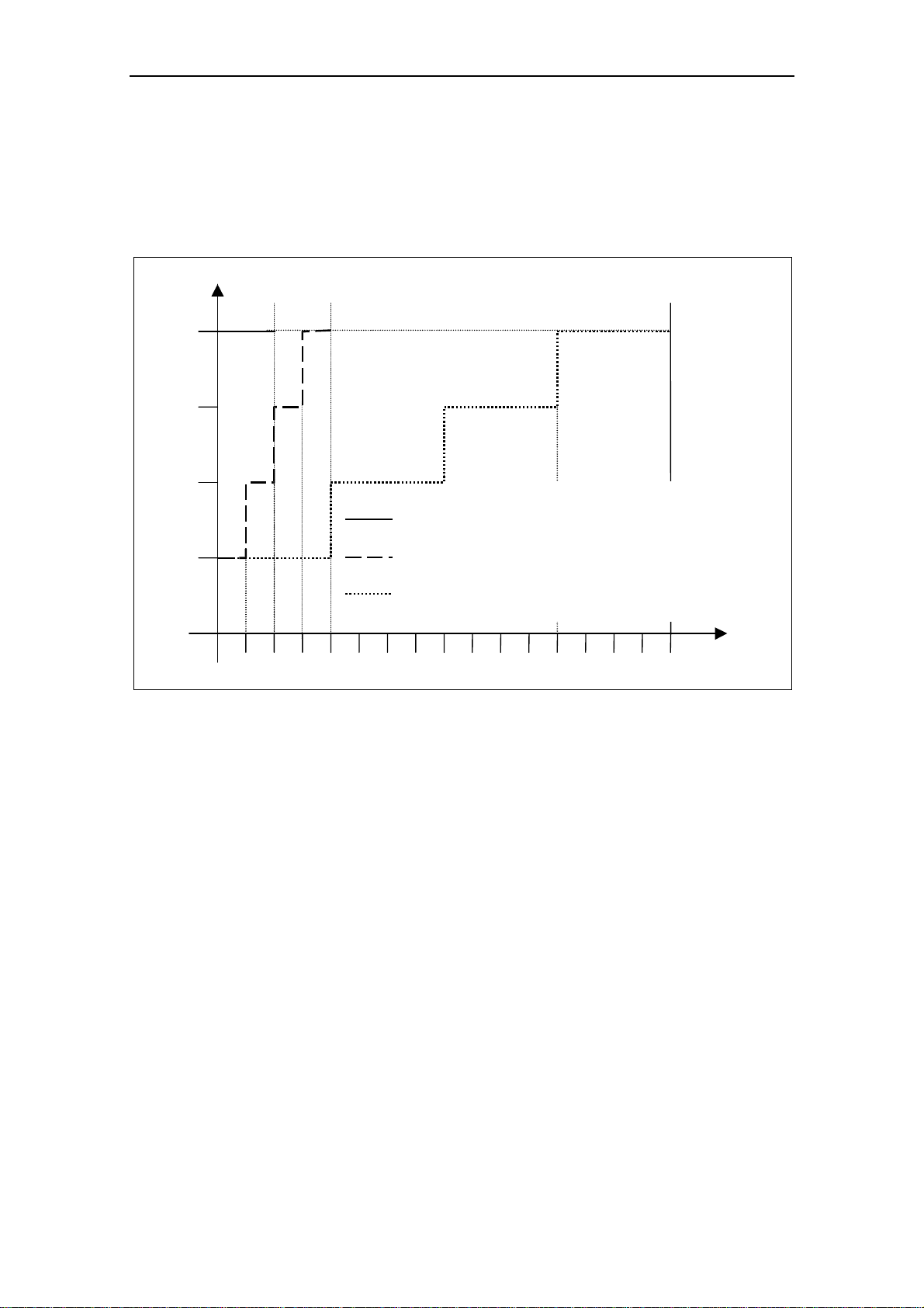
2.1 Installation after a Period of Storage
Following a prolonged period of storage, you must reform the capacitors in the
inverter.
Frame Sizes A to F
Voltage
[%]
100
75
50
0,5 1
Fig. 2-1 Forming
Frame Sizes FX and GX
Reforming the capacitors can be accomplished by applying 85% of the rated input
voltage for at least 30 minutes without load.
Storage period less than 1 year:
Storage period 1 to 2 years:
Storage period 2 to 3 years:
Storage period 3 and more years:
2468
No action necessary
Prior to energizing, connect to
voltage for one hour
Prior to energizing, form
according to the curve
Prior to energizing, form
according to the curve
Time t [h]
MICROMASTER 440 Operating Instructions
6SE6400-5AW00-0BP0
23
Page 24

2 Installation Issue 10/06
2.2 Ambient operating conditions
Temperature
Frame Sizes A to F: Frame Sizes FX and GX:
Permissible output current
[%]
100
75
Permissible output current
[%]
100
95
90
50
constant torque
-10
25
0
variable torque
10
20 30
40
50
Ambient temperatur e
Fig. 2-2 Ambient operating temp erature
Humidity Range
Relative air humidity ≤ 95 % Non-condensing
Altitude
If the inverter is to be installed at an altitude > 1000 m or > 2000 m above sea
level, derating will be required:
Permissible output current
100
%
85
80
[°C]
60
Frame Sizes
FX and GX
Frame Sizes
A to F
85
0203010 40
Permissible input voltage
100
%
80
77
[°C]
50 55
45
Ambient temper at u r e
01000
Instal l at i on altitud e in m above sea level
2000
3000 4000
01000
Installation altitude in m above sea level
2000
3000 4000
Fig. 2-3 Installation altitude
Shock and Vibration
Do not drop the inverter or expose to sudden shock. Do not install the inverter in an
area where it is likely to be exposed to constant vibration.
Mechanical strength to EN 60721-33
¾ Deflection: 0.075 mm (10 ... 58 Hz)
¾ Acceleration: 9.8 m/s
2
(> 58 ... 200 Hz)
Electromagnetic Radiation
Do not install the inverter near sources of electromagnetic radiation.
MICROMASTER 440 Operating Instructions
24 6SE6400-5AW00-0BP0
Page 25

Issue 10/06 2 Installation
Atmospheric Pollution
Do not install the inverter in an environment, which contains atmospheric pollutants
such as dust, corrosive gases, etc.
Water
Take care to site the inverter away from potential water hazards, e.g. do not install
the inverter beneath pipes that are subject to condensation. Avoid installing the
inverter where excessive humidity and condensation may occur.
Installation and cooling
CAUTION
The inverters MUST NOT be mounted horizontally.
The inverters can be mounted without any clearance at either side. When mounting
inverters one above the other, the specified environmental conditions must not be
exceeded.
Independent of this, these minimum distances must be observed.
¾ Frame Size A, B, C above and below 100 mm
¾ Frame Size D, E above and below 300 mm
¾ Frame Size F above and below 350 mm
¾ Frame Size FX, GX above 250 mm
below 150 mm
in front 40 mm (FX), 50 mm (GX)
No equipment that could have a negative effect on the flow of cooling air should be
installed in this area. Make sure that the cooling vents in the inverter are positioned
correctly to allow free movement of air.
MICROMASTER 440 Operating Instructions
6SE6400-5AW00-0BP0
25
Page 26

2 Installation Issue 10/06
2.3 Mechanical installation
WARNING
¾ To ensure the safe operation of the equipment, it must be installed and
commissioned by qualified personnel in full compliance with the warnings laid
down in these operating instructions.
¾ Take particular note of the general and regional installation and safety
regulations regarding work on dangerous voltage installations (e.g. EN 50178),
as well as the relevant regulations regarding the correct use of tools and
personal protective equipment (PPE).
¾ The mains input, DC and motor terminals, can carry dangerous voltages even
if the inverter is inoperative; wait 5 minutes to allow the unit to discharge after
switching off before carrying out any installation work.
¾ The inverters can be mounted without any clearance at either side. When
mounting inverters one above the other, the specified environmental
conditions must not be exceeded. Independent of this, these minimum
distances must be observed.
• Frame Size A, B, C above and below 100 mm
• Frame Size D, E above and below 300 mm
• Frame Size F above and below 350 mm
• Frame Size FX, GX above 250 mm
below 150 mm
in front 40 mm (FX), 50 mm (GX)
¾ If the front cover (Frame Sizes FX and GX) has been removed, the fan
impeller is exposed. There is danger of injury when the fan is running.
¾ IP20 protection is only against direct contact, always use these products within
a protective cabinet.
4
Removing from transport pallet (only for frame sizes FX and GX)
During transport, the inverter is fastened on the transport pallet with the aid of two
iron brackets.
WARNING
Note that the center of gravity of the inverter is not in the middle of the unit. When
lifting the pallet, the unit can therefore suddenly change position and swing to the
side.
1. Fasten the hoisting crane cable to the hoisting eyes on the inverter (2 eyes,
see Fig. 2-9 and Fig. 2-10).
2. Remove the two retaining bolts at the top of the front cover.
3. Unscrew the bolts in the iron brackets on the transport pallet and lift the
inverter off the pallet.
4. Once installation has been completed and the inverter connected, fasten the
two retaining bolts for the front cover at the bottom side of the door.
MICROMASTER 440 Operating Instructions
26 6SE6400-5AW00-0BP0
Page 27

Issue 10/06 2 Installation
Frame Sizes A to F
Frame Size A
55 mm
2.2"
160 mm
6.30"
Ø 4.5 mm
0.17"
Frame Size B Frame Size C
Ø 5.5 mm
Ø 4.8 mm
0.19"
138 mm
5.43"
174 mm
6.85"
0.22"
174 mm
6.85"
Frame Size D Frame Size E Frame Size F
Ø 17.5 mm
0.68"
486 mm
19.13"
Ø 17.5 mm
0.68"
616.4 mm
24.27"
Ø 15 mm
0.59"
204 mm
8.03"
810 mm
31.89"
with
filter
1110 mm
43.70"
235 mm
9.25"
235 mm
9.25"
Fig. 2-4 Drill pattern for MICROMASTER 440
300 mm
11.81"
MICROMASTER 440 Operating Instructions
6SE6400-5AW00-0BP0
27
Page 28
2 Installation Issue 10/06
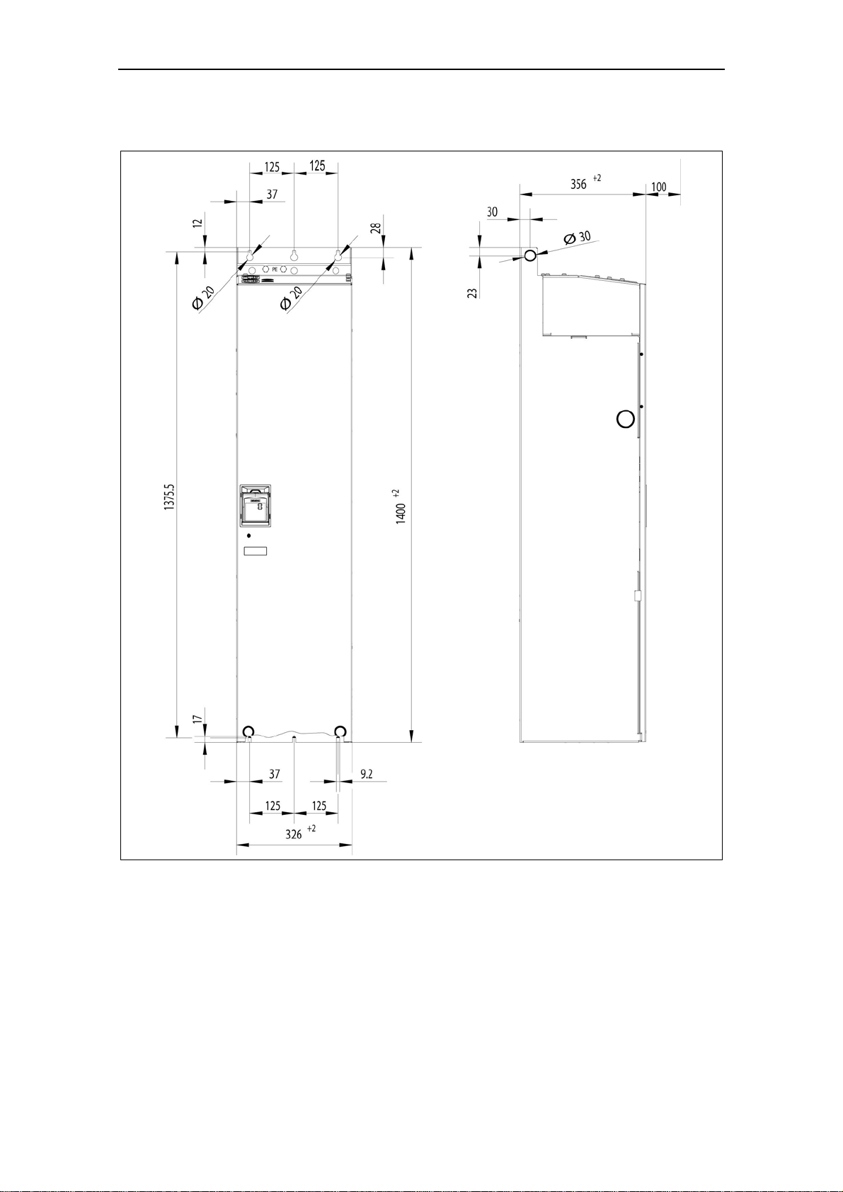
Frame Size FX
Fig. 2-5 Installation dimensions for MICROMASTER 440 Frame size FX
MICROMASTER 440 Operating Instructions
28 6SE6400-5AW00-0BP0
Page 29
Issue 10/06 2 Installation
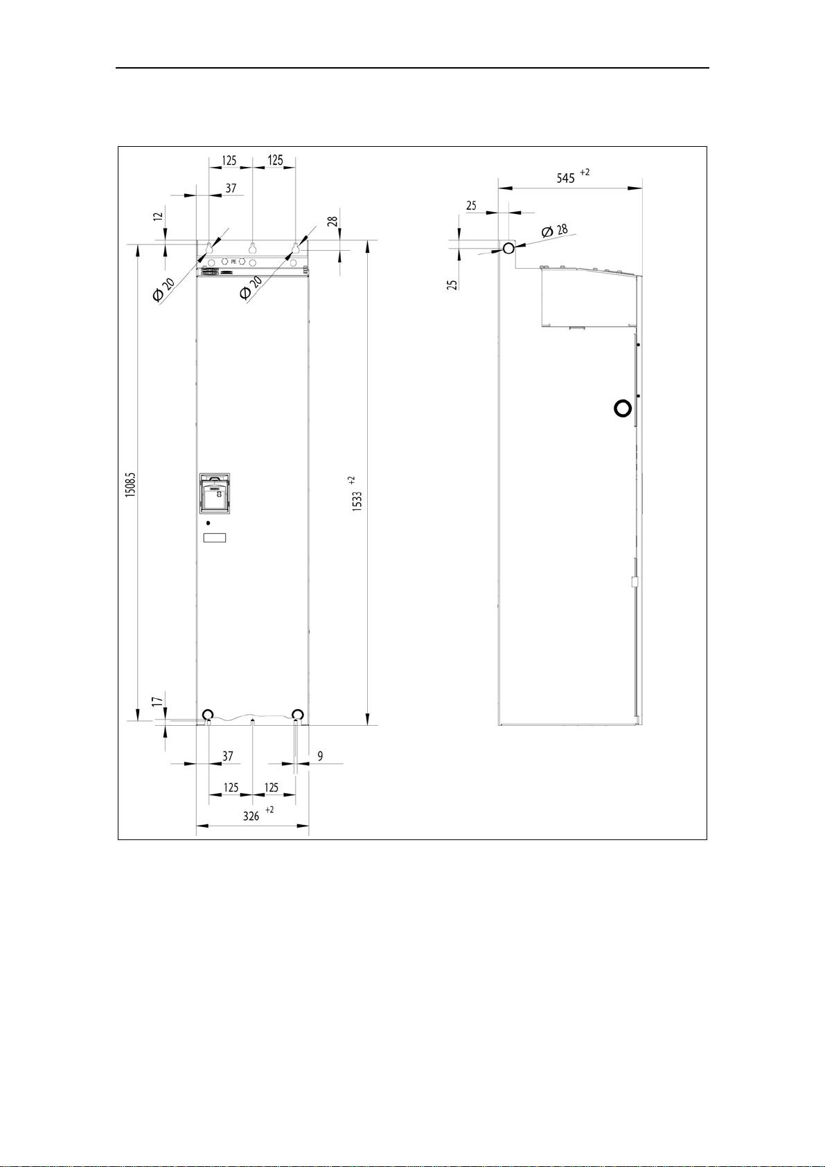
Frame Size GX
Fig. 2-6 Installation dimensions for MICROMASTER 440 Frame size GX
MICROMASTER 440 Operating Instructions
6SE6400-5AW00-0BP0
29
Page 30

2 Installation Issue 10/06
Table 2-1 Dimensions and Torques of MICROMASTER 440
Frame-Size Overall Dimensions Fixing Method Tightening Torque
2 M4 Bolts
4 M4 Nuts
4 M4 Washers or fitting on a
standard rail
4 M4 Bolts
4 M4 Nuts
4 M4 Washers
4 M5 Bolts
4 M5 Nuts
4 M5 Washers
4 M8 Bolts
4 M8 Nuts
4 M8 Washers
4 M8 Bolts
4 M8 Nuts
4 M8 Washers
4 M8 Bolts
4 M8 Nuts
4 M8 Washers
6 M8 Bolts
6 M8 Nuts
6 M8 Washers
6 M8 Bolts
6 M8 Nuts
6 M8 Washers
2,5 Nm
with washers fitted
2,5 Nm
with washers fitted
2,5 Nm
with washers fitted
3,0 Nm
with washers fitted
3,0 Nm
with washers fitted
3,0 Nm
with washers fitted
13 Nm +30 %
with washers fitted
13 Nm +30 %
with washers fitted
A
B
C
D
E
F
FX
GX
Width x
Height x
Depth
Width x
Height x
Depth
Width x
Height x
Depth
Width x
Height x
Depth
Width x
Height x
Depth
Width x
Height x
Depth
Width x
Height x
Depth
Width x
Height x
Depth
mm 73 x 173 x 149
inch 2,87 x 6,81 x 5,87
mm 149 x 202 x 172
inch 5,87 x 7,95 x 6,77
mm 185 x 245 x 195
inch 7,28 x 9,65 x 7,68
mm 275 x 520 x 245
inch 10,82 x 20,47 x 9,65
mm 275 x 650 x 245
inch 10,82 x 25,59 x 9,65
350 x 850 mm x 320
mm
height with filter 1150
13,78 x 33,46 x 12,60
inch
height with filter 45,28
mm 326 x 1400 x 356
inch 12,80 x 55,12 x 12,83
mm 326 x 1533 x 545
inch 12,80 x 60,35 x 21,46
MICROMASTER 440 Operating Instructions
30 6SE6400-5AW00-0BP0
Page 31
Issue 10/06 2 Installation
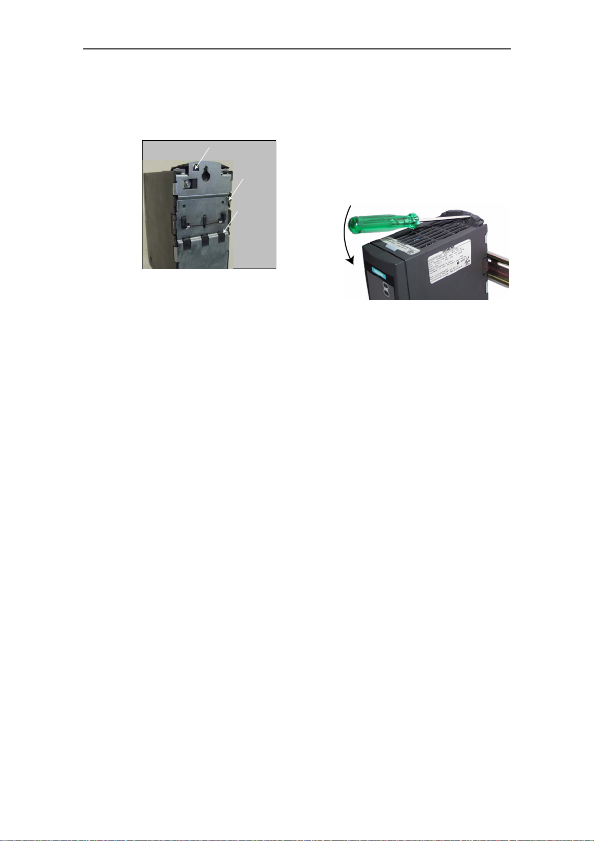
2.3.1 Mounting onto standard rail, Frame Size A
Mounting the inverter onto a 35 mm standard rail (EN 50022)
Release Mechanism
1. Locate the inverter on the mounting rail using
the upper rail latch
Upper
rail latch
Lower
rail latch
Removing the Inverter from the rail
1. To disengaged the release mechanism of the inverter, insert a screwdriver into
the release mechanism.
2. Apply a downward pressure and the lower rail latch will disengage.
3. Pull the inverter from the rail.
2. Using a flat blade screwdriver, press the
release mechanism downwards and engage
the inverter into the lower rail latch.
MICROMASTER 440 Operating Instructions
6SE6400-5AW00-0BP0
31
Page 32

2 Installation Issue 10/06
2.3.2 Installing communication options and/or pulse encoder evaluation module
Sizes A to F
NOTE
When installing the following options – PROFIBUS module, DeviceNet module,
CANopen option module and/or pulses encoder evaluation module, the mounting
depth of the drive inverter is increased!
Please refer to the relevant Operating Instructions for the actual procedure.
Sizes FX and GX
The front cover of the MICROMASTER 440 is designed so that the control module
(normally the SDP) is almost flush with the opening in the front cover.
If more than one option is to be installed in the electronic box, it is necessary to
position the entire electronic box further to the rear
Installing the options
¾ Remove the front cover:
• Unscrew two screws at the bottom side of the front cover.
• Lift front cover up and out.
¾ Remove retaining screws on the electronic box.
¾ Screw on electronic box in correct installation position as shown in Fig. 2-7
¾ Install additional options.
¾ Reinstall front cover.
Fig. 2-7 Options for the electronic box
Installation position 2
Installation position 1
Standard installation
Standard installation
Installation position 1
Installation position 2
MICROMASTER 440 Operating Instructions
32 6SE6400-5AW00-0BP0
Page 33

Issue 10/06 2 Installation
2.4 Electrical installation
WARNING
The inverter must always be grounded.
¾ To ensure the safe operation of the equipment, it must be installed and
commissioned by qualified personnel in full compliance with the warnings laid
down in these operating instructions.
¾ Take particular note of the general and regional installation and safety
regulations regarding work on dangerous voltage installations (e.g. EN 50178),
as well as the relevant regulations regarding the correct use of tools and
personal protective gear.
¾ Never use high voltage insulation test equipment on cables connected to the
inverter.
¾ The mains input, DC and motor terminals, can carry dangerous voltages even
if the inverter is inoperative; wait 5 minutes to allow the unit to discharge after
switching off before carrying out any installation work.
¾ If the front cover (Frame Sizes FX and GX) has been removed, the fan
impeller is exposed. There is danger of injury when the fan is running.
CAUTION
The control, power supply and motor leads must be laid separately. Do not feed
them through the same cable conduit/trunking.
MICROMASTER 440 Operating Instructions
6SE6400-5AW00-0BP0
33
Page 34

2 Installation Issue 10/06
2.4.1 General
WARNING
The inverter must always be grounded. If the inverter is not grounded correctly,
extremely dangerous conditions may arise within the inverter which could prove
potentially fatal.
Operation with ungrounded (IT) supplies
Filtered
The use of filtered MICROMASTER 4 drives on unearthed mains supplies is not
permitted.
Unfiltered
In the case of non-grounded networks, the 'Y' capacitor of the device must be
made ineffective. The procedure is described in Appendix D.
If the MICROMASTER is to remain in operation in non-grounded networks when a
ground fault occurs during the input or output phase, an output reactor must be
installed.
Operation with Residual Current Device (Frame Sizes A to F)
If an RCD (also referred to as ELCB or RCCB) is fitted, the MICROMASTER
inverters will operate without nuisance tripping, provided that:
¾ A type B RCD is used.
¾ The trip limit of the RCD is 300 mA.
¾ The neutral of the supply is grounded.
¾ Only one inverter is supplied from each RCD.
¾ The output cables are less than 50 m (screened) or 100 m (unscreened).
NOTE
The residual current operated circuit-breakers used must provide protection against
direct-current components in the fault current and must be suitable for briefly
suppressing power pulse current peaks. It is recommended to protect the
frequency inverter by fuse separately.
The regulations of the individual country (e.g. VDE regulations in Germany)
and the regional power suppliers must be observed!
MICROMASTER 440 Operating Instructions
34 6SE6400-5AW00-0BP0
Page 35

Issue 10/06 2 Installation
2.4.2 Power and motor connections
WARNING
The inverter must always be grounded.
♦ Isolate the mains electrical supply before making or changing connections to
the unit.
♦ Ensure that the inverter is configured for the correct supply voltage:
MICROMASTERS must not be connected to a higher voltage supply.
♦ When synchronous motors are connected or when coupling several motors in
parallel, the inverter must be operated with V/f control characteristic (P1300 =
0, 2 or 3).
CAUTION
After connecting the power and motor cables to the proper terminals, make sure
that the front covers have been replaced properly before supplying power to the
unit!
NOTICE
♦ Ensure that the appropriate circuit-breakers/fuses with the specifie d current
rating are connected between the power supply and inverter (see chapter 5,
Tables 5-5).
♦ Use Class 1 60/75
o
C copper wire only (for UL compliance). For tightening
torque see Table 5-2.
Operation with long cables
All inverters will operate at full specification with cable lengths as follows:
Frame Sizes A to F FX and GX
screened 50 m 100 m
unscreened 100 m 150 m
Using the output chokes specified in catalogue DA 51.2, the following cable leng t hs
are possible for the appropriate frame sizes:
Supply Voltage 200 V …
240 V ± 10%
Frame Sizes A … F A … B C D … F FX, GX A … C D … F FX, GX C D … F
screened 200 m 150 m 200 m 200 m 300 m 100 m 200 m 300 m 100 m 200 m
unscreened 300 m 225 m 300 m 300 m 450 m 150 m 300 m 450 m 150 m 300 m
CAUTION
If using output chokes operation is only permissible with a pulse frequency of
4 kHz. Make shure that the automatic pulse frequency reductions are disabled.
Coercing required parameter adjusting: P1800 = 4 kHz , P0290 = 0 or 1.
380 V … 400 V ± 10 % 401 V … 480 V ± 10 % 500 V … 600 V
± 10%
MICROMASTER 440 Operating Instructions
6SE6400-5AW00-0BP0
35
Page 36

2 Installation Issue 10/06
Access to the power and motor terminals
Access to the power supply and motor terminals is possible by removing the front
covers (See Fig. 2-8 to Fig. 2-10). See also Appendix B.
After removing the front covers and exposing the terminals, complete power and
motor connections as shown in Fig. 2-11.
Connection of braking unit (only for framesize FX and GX)
A passage opening for access to the intermediate circuit connections has been
provided on the top side of the inverter. It is possible to connect an external braking
unit (refer to Catalog DA65.11 or DA65.10) to these terminals. The position is
shown in Fig. 2-9 and Fig. 2-10.
The maximum cross section of connections is 50 mm², but only provided the
crimped area of cable shoes on the equipment side is provided with a heatshrinkable sleeve. This measure is important to ensure that air gaps and creep
distances are observed.
MICROMASTER 440 Operating Instructions
36 6SE6400-5AW00-0BP0
Page 37

Issue 10/06 2 Installation
Fig. 2-8 MICROMASTER 440 C onnection Terminals
MICROMASTER 440 Operating Instructions
6SE6400-5AW00-0BP0
37
Page 38
2 Installation Issue 10/06
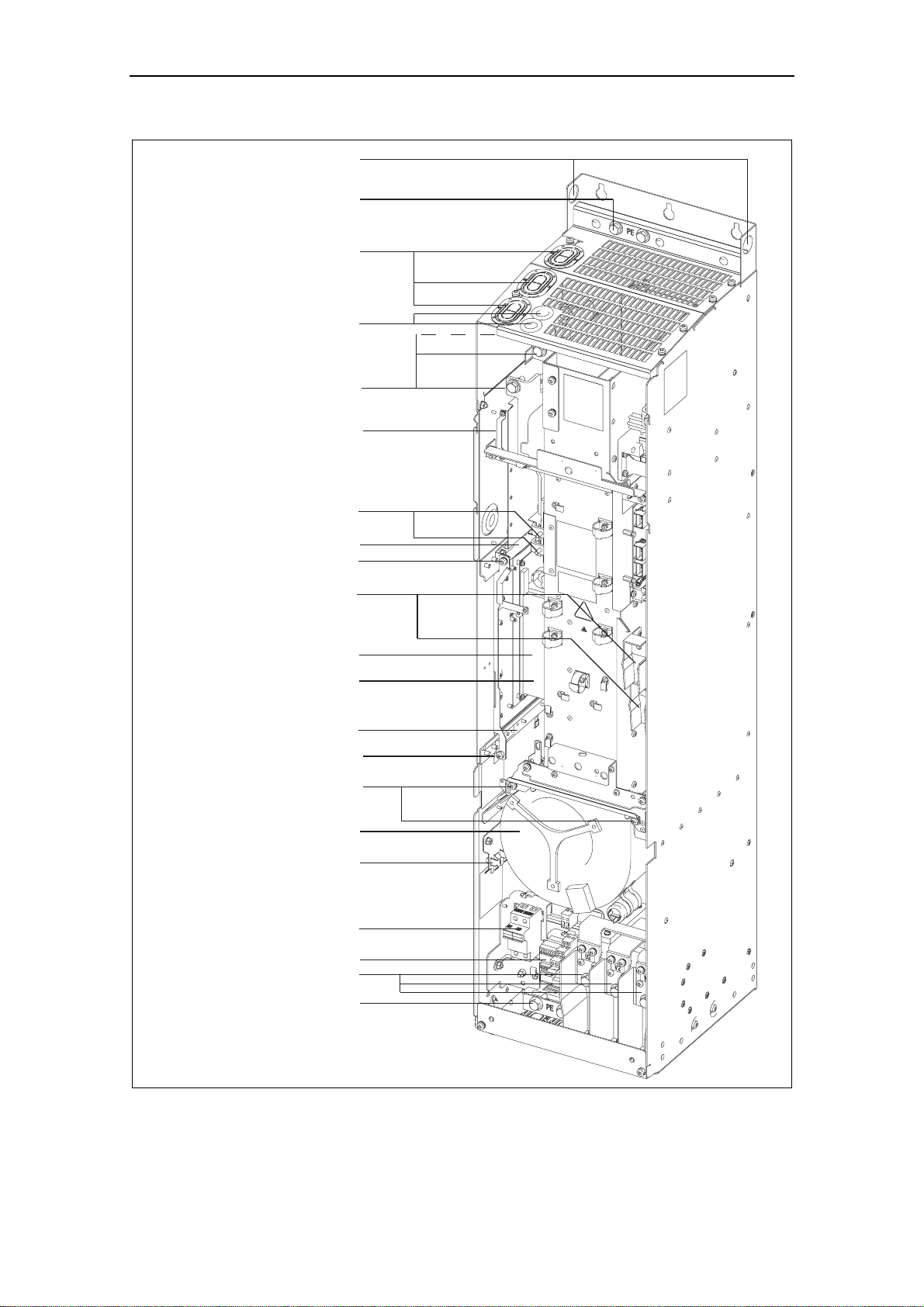
Hoisting eyes
Shield connection
Mains cable PE
Cable opening for
mains conection
U1/L1, V1/L2, W1/L3
Cable opening DCPA, DCNA
for connection of an
external braking unit
Mains cable
Phase U1/L1, V1/L2, W1/L3
Connection to
Y-Capacitor
Connection DCPA, DCNA
for external braking unit
Top adjustment rail
Top retaining screw
Connection for dv/dt filter
DCPS, DCNS
Status Display Panel
Elektronic box
Bottom adjustment rail
Bottom retaining screw
Fan screws
Fan
Shield connection
control leads
Fan fuses
Transformer adaption
PE Shield connection
Motor cable
Phase U2, V2, W2
Motor cable
Fig. 2-9 MICROMASTER 440 conn ection drawing – frame size FX
MICROMASTER 440 Operating Instructions
38 6SE6400-5AW00-0BP0
Page 39

Issue 10/06 2 Installation
Hoisting eyes
Shield connection
Mains cable PE
Cable opening for
mains conection
U1/L1, V1/L2, W1/L3
able opening DCPA, DCNA
for connection of an
external braking unit
Phase U1/L1, V1/L2, W1/L3
Connection DCPA, DCNA
for external braking unit
Connection for dv/dt filter
Status Display Panel
Bottom adjustment rail
Bottom retaining screw
Mains cable
Connection to
Y-Capacitor
Top adjustment rail
Top retaining screw
DCPS, DCNS
Elektronic box
Fan screws
Fan
Shield connection
control leads
Fan fuses
Transformer adaption
Motor cable
Phase U2, V2, W2
PE Shield connection
Motor cable
Fig. 2-10 MICROMASTER 440 conn ection drawing - frame size GX
MICROMASTER 440 Operating Instructions
6SE6400-5AW00-0BP0
39
Page 40

2 Installation Issue 10/06
Frame Sizes A to F
L3
L2
L1
N
Fuse
L3
L2
L1
Fuse
Contactor
Contactor
Single Phase
Optional
line choke
PE
Three Phase
Optional
line choke
PE
Optional
Filter
PE
Optional
Filter
PE
MICROMASTER
L/L1
U
V
N/L2
W
PE
MICROMASTER
L3
U
L2
V
L1
W
PE
1)
1)
Motor
Motor
1) with and with out filter
Frame Sizes FX and GX
L3
L2
L1
Optional
Filter
PE
2)
without filter
Contactor
Fuse
3) the commutation choke is to be earthed using the designated earthing point
Fig. 2-11 Motor and Power Connections
Optional
line choke
3)
MICROMASTER
L3
U
L2
V
L1
W
PE
2)
Motor
MICROMASTER 440 Operating Instructions
40 6SE6400-5AW00-0BP0
Page 41

Issue 10/06 2 Installation
Adaptation of fan voltage (only for frame size FX and GX)
A transformer is installed to adapt the existing line voltage to the fan voltage.
It may be necessary to reconnect the transformer terminals on the primary side to
coincide with the existing line power.
0V 1L380V
Fig. 2-12 Adaptation of fan voltage
CAUTION
If the terminals are not reconnected to the actually present line voltage, the fan
fuses can blow.
Replacement for fan fuses
Frame size Fuses (2 each) Recommended fuses
FX (90 kW CT) 1 A / 600 V / slow-acting Cooper-Bussmann FNQ-R-1, 600 V
FX (110 kW CT) 2,5 A / 600 V / slow-acting Ferraz Gould Shawmut ATDR2-1/2, 600 V
GX (132-200 kW CT) 4 A / 600 V / slow-acting Ferraz Gould Shawmut ATDR4, 600 V
1L400V 1L440V
Connect according input voltage
1L480V -
or comparable fuse
or comparable fuse
or comparable fuse
MICROMASTER 440 Operating Instructions
6SE6400-5AW00-0BP0
41
Page 42
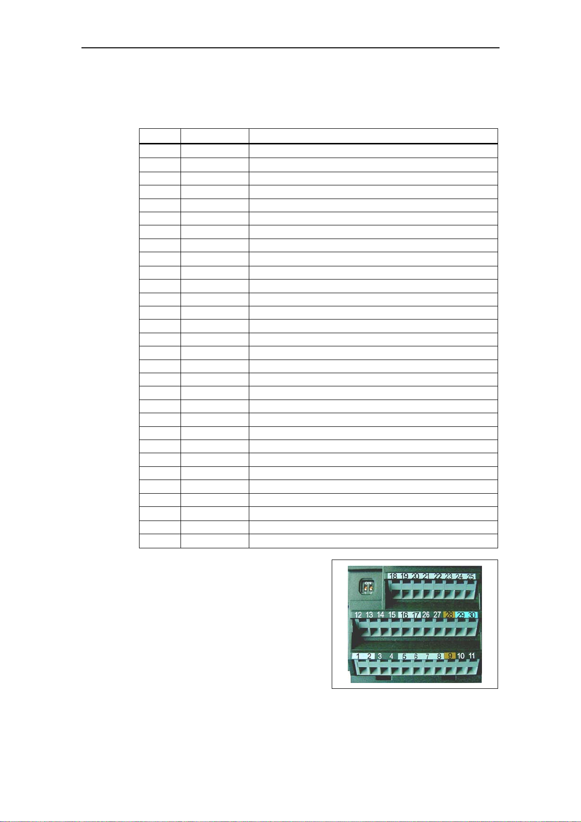
2 Installation Issue 10/06
2.4.3 Control terminals
Permitted cable diameters: 0.08 … 2.5 mm2 (AWG: 28 … 12)
Terminal Designation Function
1
−
2
−
3 ADC1+ Analog input 1 (+)
4 ADC1- Analog input 1 (-)
5 DIN1 Digital input 1
6 DIN2 Digital input 2
7 DIN3 Digital input 3
8 DIN4 Digital input 4
9
−
10 ADC2+ Analog input 2 (+)
11 ADC2- Analog input 2 (-)
12 DAC1+ Analog output 1 (+)
13 DAC1- Analog output 1 (-)
14 PTCA Connection for PTC / KTY84
15 PTCB Connection for PTC / KTY84
16 DIN5 Digital input 5
17 DIN6 Digital input 6
18 DOUT1/NC Digital output 1 / NC contact
19 DOUT1/NO Digital output 1 / NO contact
20 DOUT1/COM Digital output 1 / Changeover contact
21 DOUT2/NO Digital output 2 / NO contact
22 DOUT2/COM Digital output 2 / Changeover contact
23 DOUT3/NC Digital output 3 / NC contact
24 DOUT3/NO Digital output 3 / NO contact
25 DOUT3/COM Digital output 3 / Changeover contact
26 DAC2+ Analog output 2 (+)
27 DAC2- Analog output 2 (-)
28
−
29 P+ RS485 port
30
N−
Output +10 V
Output 0 V
Isolated output +24 V / max. 100 mA
Isolated output 0 V / max. 100 mA
RS485 port
Fig. 2-13 Control terminals of
MICROMASTER 440
A detailed description of the inputs and outputs is provided in Section 3.6.
MICROMASTER 440 Operating Instructions
42 6SE6400-5AW00-0BP0
Page 43

Issue 10/06 2 Installation
2.4.4 Avoiding Electro-Magnetic Interference (EMI)
The inverters are designed to operate in an industrial environment where a high
level of EMI can be expected. Usually, good installation practices will ensure safe
and trouble-free operation. If you encounter problems, follow the guidelines stated
below.
Action to Take
¾ Ensure that all equipment in the cubicle is well grounded using short, thick
grounding cable connected to a common star point or busbar
¾ Make sure that any control equipment (such as a PLC) connected to the
inverter is connected to the same ground or star point as the inverter via a short
thick link.
¾ Connect the return ground from the motors controlled by the inverters directly to
the ground connection (PE) on the associated inverter
¾ Flat conductors are preferred as they have lower impedance at higher
frequencies
¾ Terminate the ends of the cable neatly, ensuring that unscreened wires are as
short as possible
¾ Separate the control cables from the power cables as much as possible, using
separate trunking, if necessary at 90º to each other.
¾ Whenever possible, use screened leads for the connections to the control
circuitry
¾ Ensure that the contactors in the cubicle are suppressed, either with R-C
suppressors for AC contactors or 'flywheel' diodes for DC contactors fitted to the
coils. Varistor suppressors are also effective. This is important when the
contactors are controlled from the inverter relay
¾ Use screened or armored cables for the motor connections and ground the
screen at both ends using the cable clamps
WARNING
Safety regulations must not be compromised when installing inverters!
MICROMASTER 440 Operating Instructions
6SE6400-5AW00-0BP0
43
Page 44

2 Installation Issue 10/06
2.4.5 Screening Methods
Frame Sizes A, B and C
For frame sizes A, B and C the Gland Plate Kit is supplied as an option. It allows
easy and efficient connection of the necessary screening. See the Gland Plate
Installation Instructions contained on the Document CD-ROM, supplied with the
MICROMASTER 440.
Screening without a Gland Plate
Should a Gland Plate not be available, then the inverter can be screened using the
methodology shown in Fig. 2-14.
1 Mains power input
2 Control cable
3 Motor cable
4 Footprint filter
5 Metal back plate
6 Use suitable clips to fix motor and control cable screens securely to metal back plate
7 Screening cables
Fig. 2-14 Wiring Guidelines to Minimize the Effects of EMI
MICROMASTER 440 Operating Instructions
44 6SE6400-5AW00-0BP0
Page 45

Issue 10/06 2 Installation
Frame Sizes D and E
The Gland Plate is factory fitted. If the installation conditions are restricted, the
shield of the motor cable can also be attached outside the cabinet, as shown in
Fig. 2-14, for example.Frame Sizes FX and GX
Frame size F
The gland plate for the control cables is factory-fitted.
Devices without filter: The shield of the motor cable must be attached outside the
cabinet, as shown in Fig. 2-14, for example.
Devices with filter: The gland plate for the motor cable is factory-fitted.
Frame Sizes FX and GX
Connect the wire shields to the shield connection points shown in the connectio n
drawing (see Fig. 2-9 and Fig. 2-10) .
Twist the shields of the motor cables and screw them to the PE connection for the
motor cable.
When using an EMI filter, a power commutating choke is required. The wire shields
should be fastened to the metallic mounting surface as close as possible to the
components.
MICROMASTER 440 Operating Instructions
6SE6400-5AW00-0BP0
45
Page 46

2 Installation Issue 10/06
MICROMASTER 440 Operating Instructions
46 6SE6400-5AW00-0BP0
Page 47

Issue 10/06 3 Functions
3 Functions
This Section includes the following:
¾ Explanation of the MICROMASTER 440 parameters
¾ An overview of the parameter structure of MICROMASTER 440
¾ A description of the display and operator control elements and communications
¾ A block diagram of MICROMASTER 440
¾ An overview of the various ways of commissioning the MICROMASTER 440
¾ A description of the inputs and outputs
¾ Possibilities of controlling (open-loop and closed-loop) the MICROMASTER 440
¾ A description of the various functions of the MICROMASTER 440 and their
implementation
¾ Explanation and information on the protective functions
3.1
Parameters ............................................................................................................. 51
3.1.1 Setting / monitoring parameters and parameter attributes ..................................... 51
3.1.2 Interconnecting signals (BICO technology) ............................................................ 57
3.1.2.1 Selecting the command source P0700 / selecting the setpoint source P1000....... 57
3.1.2.2 Selection of command/frequency setpoint P0719 .................................................. 59
3.1.2.3 BICO technology..................................................................................................... 60
3.1.3 Data sets................................................................................................................. 63
3.1.4 Reference quantities............................................................................................... 68
3.2 Operator panels for MICROMASTER..................................................................... 70
3.2.1 Description of the BOP (Basic Operator Panel) ..................................................... 70
3.2.2 Description of the AOP (Advanced Operator Panel) .............................................. 71
3.2.3 Keys and their functions on the operator panel (BOP / AOP) ................................ 72
3.2.4 Changing parameters using the operator panel ..................................................... 73
3.3 Block diagram ......................................................................................................... 74
3.4 Factory setting ........................................................................................................ 75
3.5 Commissioning ....................................................................................................... 77
3.5.1 50/60 Hz setting...................................................................................................... 79
3.5.2 Motor circuit ............................................................................................................ 80
3.5.3 Quick commissioning.............................................................................................. 83
3.5.4 Calculating the motor / control data........................................................................ 88
3.5.5 Motor data identification.......................................................................................... 91
3.5.6 Magnetizing current ................................................................................................ 95
3.5.7 Commissioning the application............................................................................... 97
3.5.7.1 Serial Interface (USS)............................................................................................. 97
3.5.7.2 Selection of command source ................................................................................ 98
3.5.7.3 Digital input (DIN).................................................................................................... 98
3.5.7.4 Digital output (DOUT) .............................................................................................99
3.5.7.5 Selection of frequency setpoint............................................................................. 100
3.5.7.6 Analog input (ADC)............................................................................................... 101
MICROMASTER 440 Operating Instructions
6SE6400-5AW00-0BP0
47
Page 48

3 Functions Issue 10/06
3.5.7.7 Analog output (DAC)............................................................................................. 102
3.5.7.8 Motor potentiometer (MOP).................................................................................. 103
3.5.7.9 Fixed frequency (FF)............................................................................................. 104
3.5.7.10 JOG....................................................................................................................... 105
3.5.7.11 Ramp function generator (RFG) ........................................................................... 106
3.5.7.12 Reference/limit frequencies .................................................................................. 107
3.5.7.13 Inverter protection ................................................................................................. 108
3.5.7.14 Motor protection .................................................................................................... 108
3.5.7.15 Encoder................................................................................................................. 110
3.5.7.16 V/f control.............................................................................................................. 111
3.5.7.17 Field-orientated control .........................................................................................113
3.5.7.18 Converter-specific Functions ................................................................................118
3.5.7.19 Command and drive data set................................................................................ 127
3.5.7.20 Diagnostic parameters.......................................................................................... 130
3.5.7.21 End of commissioning........................................................................................... 131
3.5.8 Series commissioning........................................................................................... 132
3.5.9 Parameter reset to the factory setting................................................................... 133
3.6 Inputs / outputs ..................................................................................................... 135
3.6.1 Digital inputs (DIN)................................................................................................ 135
3.6.2 Digital outputs (DOUT) ......................................................................................... 138
3.6.3 Analog inputs (ADC) ............................................................................................. 140
3.6.4 Analog outputs (D/A converter) ............................................................................ 142
3.7 Communications ................................................................................................... 144
3.7.1 Universal serial interface (USS)............................................................................ 146
3.7.1.1 Protocol specification and bus structure............................................................... 148
3.7.1.2 The structure of net data....................................................................................... 155
3.7.1.3 USS bus configuration via COM link (RS485)...................................................... 164
3.8 Fixed frequencies (FF).......................................................................................... 167
3.9 Motorized potentiometer (MOP) ........................................................................... 170
3.10 JOG....................................................................................................................... 172
3.11 PID controller (technological controller)................................................................ 173
3.11.1 Closed-loop PID control........................................................................................ 175
3.11.1.1 PID motorized potentiometer (PID-MOP) .............................................................177
3.11.1.2 PID fixed setpoint (PID-FF)................................................................................... 178
3.11.1.3 PID dancer roll control ..........................................................................................179
3.12 Setpoint channel ................................................................................................... 181
3.12.1 Summation and modification of the frequency setpoint (AFM)............................. 181
3.12.2 Ramp-function generator (RFG)........................................................................... 183
3.12.3 OFF/braking functions .......................................................................................... 186
3.12.4 Manual / automatic operation ............................................................................... 189
3.13 Free function blocks (FFB) ................................................................................... 191
3.14 Motor holding brake (MHB)................................................................................... 196
3.15 Electronic brakes .................................................................................................. 202
3.15.1 DC braking............................................................................................................ 202
3.15.2 Compound braking................................................................................................ 205
3.15.3 Dynamic braking ................................................................................................... 206
3.16 Automatic restart................................................................................................... 211
3.17 Flying restart ......................................................................................................... 213
MICROMASTER 440 Operating Instructions
48 6SE6400-5AW00-0BP0
Page 49

Issue 10/06 3 Functions
Closed-loop Vdc control........................................................................................ 215
3.18
3.18.1 Vdc_max controller ............................................................................................... 215
3.18.2 Kinetic buffering (Vdc_min controller)................................................................... 218
3.19 Positioning down ramp ......................................................................................... 219
3.20 Monitoring functions / messages .......................................................................... 221
3.20.1 General monitoring functions / messages ............................................................ 221
3.20.2 Load torque monitoring......................................................................................... 223
3.21 Thermal motor protection and overload responses.............................................. 227
3.21.1 Thermal motor model............................................................................................ 229
3.21.2 Temperature sensor.............................................................................................. 230
3.22 Power module protection ...................................................................................... 232
3.22.1 General overload monitoring ................................................................................ 232
3.22.2 Thermal monitoring functions and overload responses........................................ 233
3.23 Open-loop/closed-loop control technique ............................................................. 235
3.23.1 V/f control.............................................................................................................. 235
3.23.1.1 Voltage boost ........................................................................................................ 237
3.23.1.2 Slip compensation................................................................................................. 239
3.23.1.3 V/f resonance damping......................................................................................... 240
3.23.1.4 V/f open-loop control with flux current control (FCC)............................................ 241
3.23.1.5 Current limiting (Imax controller)........................................................................... 242
3.23.2 Vector control........................................................................................................ 243
3.23.2.1 Vector control without speed encoder (SLVC) ..................................................... 245
3.23.2.2 Vector control with speed encoder (VC) ............................................................... 247
3.23.2.3 Speed controller.................................................................................................... 248
3.23.2.4 Closed-loop torque control.................................................................................... 253
3.23.2.5 Limiting the torque setpoint................................................................................... 254
MICROMASTER 440 Operating Instructions
6SE6400-5AW00-0BP0
49
Page 50

3 Functions Issue 10/06
WARNING
¾ MICROMASTER drive inverters operate with high voltages.
¾ When electrical equipment is operated, then specific parts of this equipment are
at hazardous voltage levels.
¾ The following terminals can carry dangerous voltages even if the inverter is
inoperative:
♦ the power supply L/L1, N/L2, L3 resp. U1/L1, V1/L2, W1/L3
♦ the motor terminals U, V, W resp. U2, V2, W2
♦ and depending on the frame size the terminals DC+/B+, DC-, B-, DC/R+
resp. DCPS, DCNS, DCPA, DCNA
¾ Emergency switching-off devices in compliance with EN 60204 IEC 204 (VDE
0113) must remain functional in all operating modes of the control device. When
the Emergency switching-off device is reset, then it is not permissible that the
equipment runs-up again in an uncontrolled or undefined way.
¾ In cases and situations where short-circuits in the control device can result in
significant material damage or even severe bodily injury (i.e. potentially
hazardous short-circuits), then additional external measures or
devices/equipment must be provided in order to ensure or force operation
without any potential hazards, even if a short-circuit occurs (e.g. independent
limit switches, mechanical interlocks etc.).
¾ Certain parameter settings can mean that the drive inverter automatically
restarts after the power supply voltage fails and then returns.
¾ The motor parameters must be precisely configured in order to ensure perfect
motor overload protection.
¾ The drive inverter provides internal motor overload protection according to
UL508C, Section 42. I
2
t monitoring is enabled in the default setting (refer to
P0610 and P0335). The motor overload protection can also be guaranteed
using an external PTC or KTY84.
¾ This equipment is suitable for use in a circuit capable of delivering not more
than 10,000 (Frame Sizes A to C) or 42,000 (Frame Sizes D to GX) symmetrical
amperes (rms), for a maximum voltage of 230 V / 460 V / 575 V when protected
by an H, J or K type fuse, a circuit breaker or self-protected combination motor
controller (for more details see Appendix F).
¾ The drive unit may not be used as 'Emergency switching-off device' (refer to
EN 60204, 9.2.5.4).
CAUTION
Only qualified personnel may commission (start-up) the equipment. Safety
measures and warnings must be always extremely carefully observed and fulfilled.
MICROMASTER 440 Operating Instructions
50 6SE6400-5AW00-0BP0
Page 51

Issue 10/06 3 Functions
3.1 Parameters
3.1.1 Setting / monitoring parameters and parameter attributes
The drive inverter is adapted to the particular application using the appropriate
parameters. This means that each parameter is identified by a parameter number ,
parameter text and specific attributes (e.g. readable, can be written into, BICO
attribute, group attribute etc.). Within any one particular drive system, the
parameter number is unique. On the other hand, an attribute can be assigned a
multiple number of times so that several parameters can have the same attribute.
For MICROMASTER, parameters can be accessed using the following operator
units:
¾ BOP (option)
¾ AOP (option)
¾ PC-based commissioning (start-up) tool "Drive Monitor" or "STARTER". These
PC-based tools are supplied on the CD-ROM.
The parameter types are the main differentiating feature of the parameters.
Fig. 3-1 Parameter types
Setting parameters
Parameters which can be written into and read – "P" parameters
These are activated/de-activated in the individual functions or parameters directly
influence the behavior of a function. The value of this parameter is saved in a nonvolatile memory (EEPROM) as long as the appropriate option was selected (nonvolatile data save). Otherwise, these values are saved in the non-volatile memory
(RAM) of the processor, which are lost after power failure or power-off/power-on
operations.
Notation:
P0927 setting parameter 927
P0748.1 setting parameter 748, bit 01
P0719[1] setting parameter 719 index 1
P0013[0...19] setting parameter 13 with 20 indices (indices 0 to 19)
Abbreviated notation
P0013[20] setting parameter 13 with 20 indices (indices 0 to 19)
Read (r....) Write/Read (P....)
"normal"
Read parameters
Parameter
BICO output BICO input
"normal"
Write-/Read parameters
MICROMASTER 440 Operating Instructions
6SE6400-5AW00-0BP0
51
Page 52

3 Functions Issue 10/06
Monitoring parameters
These can only be read – "r" parameters
These parameters are used to display internal quantities, for example states and
actual values. These parameters are absolutely necessary, especially for
diagnostics.
Notation:
r0002 monitoring parameter 2
r0052.3 monitoring parameter 52, bit 03
r0947[2] monitoring parameter 947 index 2
r0964[0...4] monitoring parameter 964 with 5 indices (indices 0 to 4)
Abbreviated notation
r0964[5] monitoring parameter 964 with 5 indices (indices 0 to 4)
NOTE
¾ A parameter (e.g. P0013[20]) with x consecutive
elements (in this case: 20) is defined using an index. x is
defined by the numerical index value. When transferred to
a parameter this means that an indexed parameter can
assume several values. The values are addressed via the
parameter number including the index value (e.g.
P0013[0], P0013[1], P0013[2], P0013[3], P0013[4], ...).
Index parameters, for example, are used for:
P0013[0]
P0013[1]
P0013[2]
.
.
.
P0013[18]
P0013[19]
Drive data sets
Command data sets
Sub-functions
In addition to the parameter number and parameter text, every setting and
monitoring parameter has different attributes which are used to individually define
the properties/characteristics of the parameter. The attributes are listed in the
following Table which are used for MICROMASTER.
Table 3-1 Parameter attributes
Attribute
group
Data types
Attribute Description
The data type of a parameter defines the maximum possible value range. 3 data
types are used for MICROMASTER. They either represent an unsigned integer value
(U16, U32) or a floating-point value (float). The value range is frequently restricted by
a minimum, maximum value (min, max) or using drive inverter/motor quantities.
U16 Unsigned, integer value with a size of 16 bits,
max. value range: 0 .... 65535
U32 Unsigned, integer value with a size of 32 bits
max. value range: 0 .... 4294967295
Float A simple precise floating point value according to the IEEE standard format
max. value range: -3.39e
+38
– +3.39e
+38
MICROMASTER 440 Operating Instructions
52 6SE6400-5AW00-0BP0
Page 53

Issue 10/06 3 Functions
Attribute
group
Value range
Unit
Access level
Attribute Description
The value range, which is specified as a result of the data type, is restricted/limited by
the minimum, maximum value (min, max) and using drive inverter/motor quantities.
Straightforward commissioning (start-up) is guaranteed in so much that the
parameters have a default value. These values (min, def, max) are permanently
saved in the drive inverter and cannot be changed by the user.
- No value entered (e.g.: "r parameter")
Min Minimum value
Def Default value
Max Maximum value
For MICROMASTER, the units of a particular parameter involve the physical quantity
(e.g. m, s, A). Quantities are measurable properties/characteristics of physical
objects, operations, states and are represented using characters of a formula (e.g. V
= 9 V).
- No dimension
% Percentage
A Ampere
V Volt
Ohm Ohm
us Microseconds
ms Milliseconds
s Seconds
Hz Hertz
kHz Kilohertz
1/min Revolutions per minute [RPM]
m/s Meters per second
Nm Newton meter
W Watt
kW Kilowatt
Hp Horse power
kWh Kilowatt hours
°C Degrees Celsius
m Meter
kg Kilograms
° Degrees (angular degrees)
The access level is controlled using parameter P0003. In this case, only those
parameters are visible at the BOP or AOP, where the access level is less than or
equal to the value assigned in parameter P0003. On the other hand, for DriveMonitor
and STARTER, only access levels 0 and 4 are relevant. For example, parameters
with access level 4 cannot be changed if the appropriate access level has not been
set.
The following access levels are implemented in the family of MICROMASTER drive
units:
0 User-defined parameter list (refer to P0013)
1 Standard access to the most frequently used parameters
2 Extended access, e.g. to drive inverter I/O functions
3 Expert access only for experienced users
4 Service access only for authorized service/maintenance personnel – with password
protection.
As far as the ability to visualize the parameters is concerned, the group assignment of
the individual parameters must be taken into account. Parameter P0004 is used for
the control (refer to the Grouping).
MICROMASTER 440 Operating Instructions
6SE6400-5AW00-0BP0
53
Page 54

3 Functions Issue 10/06
Attribute
group
Grouping
BICO
Data sets
Change state
QC.
Active
Attribute Description
The parameters are sub-divided into groups according to their functionality. This
ALWAYS 0 all parameters
INVERTER 2 drive inverter parameters 0200 .... 0299
MOTOR 3 motor parameters 0300 .... 0399 and
ENCODER 4 speed encoder 0400 .... 0499
TECH_APL 5 technical applications / units 0500 .... 0599
COMMANDS 7 control commands, digital I/O 0700 .... 0749 and
TERMINAL 8 Analog inputs/outputs 0750 .... 0799
SETPOINT 10 Setpoint channel and ramp-function gen. 1000 .... 1199
FUNC 12 Drive inverter functions 1200 .... 1299
CONTROL 13 Motor open-loop/closed-loop control 1300 .... 1799
COMM 20 Communications 2000 .... 2099
ALARMS 21 Faults, warnings, monitoring functions" 2100 .... 2199
TECH 22 Technological controller (PID controller) 2200 .... 2399
Description for Binector Input (BI), Binector Output (BO), Connector Input (CI),
BI Binector Input
BO Binector Output
CI Connector Input
CO Connector Output
CO/BO Connector Output / Binector Output
Description for the command data set (CDS) and drive data set (DDS) refer to Section
CDS Command data set
DDS Drive data set
"P" parameters can only be changed depending on the drive state. The parameter
C Quick commissioning (start-up)
U Operation (run)
T Ready
This parameter attribute identifies as to whether the parameter is included in the quick
No The parameter is not included in the quick commissioning (start-up)
Yes The parameter is included in the quick commissioning (start-up)
This attribute is only of importance in conjunction with a BOP. The "Immediate"
Immediately
After
actuation
increases the transparency and allows a parameter to be quickly searched for.
Furthermore, parameter P0004 can be used to control the ability to be visualized for
the BOP / AOP.
Main parameter area:
0600 .... 0699
0800 .... 0899
Connector Output (CO) and Connector Output / Binector Output (CO/BO), refer to
Section 3.1.2.3
3.1.3
value is not accepted if the instantaneous state is not listed in the parameter attribute
"Change state". For instance, the commissioning (start-up) parameter P0010 with the
attribute "CT" can only be changed in quick start-up "C" or ready "T" but not in run
"U".
commissioning (start-up) (P0010 = 1).
attribute indicates that this value is already accepted when scrolling (when changing
the value with
functions have this property (e.g. constant voltage boost P1310 or filter time
constants). On the other hand, for parameters with the attribute "After actuation", the
value is only accepted after first actuating the key
parameters where the parameter value can have different settings/meanings (e.g.
selecting the frequency setpoint source P1000).
The value becomes valid by either scrolling with
The value is only accepted by pressing
or ). Especially parameters which are used for optimization
. These include, for example,
or
MICROMASTER 440 Operating Instructions
54 6SE6400-5AW00-0BP0
Page 55

Issue 10/06 3 Functions
The attributes and groups are shown, in the parameter list, in the header line of the
parameter. This is shown as an example in Fig. 3-2 using parameter P0305.
Index
BICO (if available) Access level
P0305[3]
Rated motor current
CStat:
P-Group:
Group
CStat
C
MOTOR first confirm
Datatype: Float
Active:
Active
Datatypes
Unit Def:
A3.25
QuickComm. Yes
QuickComm.
Unit
0.01
Min:
Max:
Value range
10000.0
0
Level:
1
Fig. 3-2 Header line for parameter P0305
MICROMASTER 440 Operating Instructions
6SE6400-5AW00-0BP0
55
Page 56
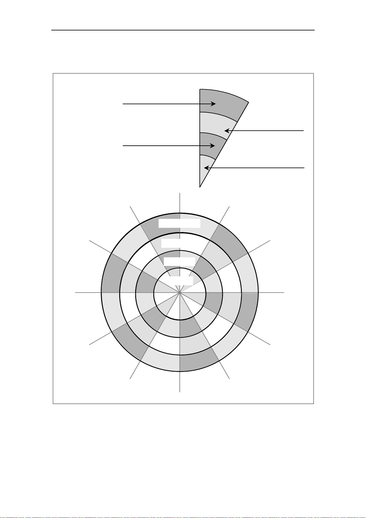
3 Functions Issue 10/06
The interrelationship between access level P0003 and the grouping P0004 is
schematically shown in Fig. 3-3.
User access level
P0003 = 1
2
3
4
Standard
Extended
Expert
Service
P0004 = 0
(no filter function)
allows direct access
to the parameters.
For BOP and AOP
depending on the
selected access level
P0004 = 21
Alarms, Warnings &
Monitoring
P0004 = 2, P0003 = 1
Parameters level 1
concerning the inverter unit
P0004 = 2, P0003 = 3
Parameters level 1, 2 and 3
concerning the inverter unit
P0004 = 22
PID Controller
P0003 = 1
P0003 = 2
P0004 = 2
Inverter Unit
P0004 = 2, P0003 = 2
Parameters level 1 and 2
concerning the inverter unit
P0004 = 2, P0003 = 4
Parameters level 1, 2, 3 and 4
concerning the inverter unit
P0004 = 2
Inverter Unit
P0200 ... P0299
P0004 = 3
Motor Data
P0300 ... P0399
P0600 ... P0699
P0004 = 20
Communication
P2000 ... P2099
P0004 = 13
Motor Control
P1300 ... P1799
P0004 = 12
Drive Features
P1200 ... P1299
P0004 = 10
Setpoint Channel &
Ramp Generator
P1000 ... P1199
Fig. 3-3 Parameter grouping / access
P0003 = 3
P0003 = 4
P0004 = 8
Analogue I/O
P0750 ... P0799
P0004 = 4
Speed sensor
P0400 ... P0499
P0004 = 5
Technology
Application / units
P0400 ... P0499
P0004 = 7
Commands and
Digital I/O
P0700 ... P0749
P0800 ... P0899
MICROMASTER 440 Operating Instructions
56 6SE6400-5AW00-0BP0
Page 57

Issue 10/06 3 Functions
3.1.2 Interconnecting signals (BICO technology)
A state-of-the-art drive unit must be able to interconnect internal and external
signals (setpoint / actual values and control / status signal). This interconnection
functionality must have a high degree of flexibility in order to be able to adapt the
drive to new applications. Further, a high degree of usability is required, which also
fulfills standard applications. This is the reason that within the MICROMASTER
series of drive units, BICO technology (→ flexibility) and fast parameterization
using parameters P0700 / P1000 (→ usability) or P0719 (→ combination
P0700/P1000) have been introduced to be able to fulfill both of these requirements.
3.1.2.1 Selecting the command source P0700 / selecting the setpoint source P1000
The following parameters can be used to quickly interconnect setpoints and control
signals:
¾ P0700 "Selection of command source"
¾ P1000 "Selection of setpoint source"
These parameters are used to define via which interface the drive inverter receives
the setpoint or the power-on/power-off command. The interfaces, listed in Table
3-2 can be selected for the command source P0700.
Table 3-2 Parameter P0700
Parameter values Significance / command source
0
1
2
4
5
6
Factory default
BOP (operator panel, refer to Section 3.2.1)
Terminal strip
USS on BOP link
USS on COM link
CB on COM link
The following internal or external sources / interfaces can be selected for the
frequency setpoint source P1000. In addition to the main setpoint (1
supplementary setpoint (2
nd
position) can be selected (refer to Table 3-3).
st
position), a
MICROMASTER 440 Operating Instructions
6SE6400-5AW00-0BP0
57
Page 58

3 Functions Issue 10/06
Table 3-3 Parameter P1000
Parameter values
0
1
2
3
4
5
6
7
10
11
12 Analog setpoint MOP setpoint
..
..
..
77
Main setpoint source Supplementary setpoint source
No main setpoint MOP setpoint (motorized
potentiometer)
Analog setpoint -
Fixed frequency USS on BOP link -
USS on COM link CB on COM link Analog setpoint 2 -
No main setpoint MOP setpoint
MOP setpoint MOP setpoint
.. ..
.. ..
.. ..
Analog setpoint 2 Analog setpoint 2
Significance
-
NOTE
¾ Communications between the AOP and MICROMASTER are established using
the USS protocol. The AOP can be connected to both the BOP link (RS 232) as
well as at the COM link interface (RS 485) of the drive inverter. If the AOP is to
be used as command source or setpoint source then for parameter P0700 or
P1000, either "USS on BOP link" or "USS on COM link" should be selected.
¾ The complete list of all of the setting possibilities can be taken from the
parameter list (refer to parameter list P1000).
¾ Parameters P0700 and P1000 have the following default settings:
a) P0700 = 2 (terminal strip)
b) P1000 = 2 (analog setpoint)
In this case, the selection of the command source is made independently of the
selection of the frequency setpoint source. This means that the source to enter the
setpoint does not have to match the source to enter the power-on/power-off command (command source). This means, for example, that the setpoint (P1000 = 4)
can be connected via an external device which is connected to the BOP link
interface via USS and the control (ON/OFF command, etc.) is entered via digital
inputs (terminals, P0700 = 2).
CAUTION
¾ When P0700 or P1000 are modified, then the frequency inverter also changes
the subordinate BICO parameters (refer to the parameter list for P0700 or
P1000 in the appropriate tables)
¾ There is no prioritization (priority assignment) between direct BICO
parameterization and P0700/P1000. The last modification is valid.
MICROMASTER 440 Operating Instructions
58 6SE6400-5AW00-0BP0
Page 59

Issue 10/06 3 Functions
3.1.2.2 Selection of command/frequency setpoint P0719
Parameter P0719 represents a combination of the functionalities of the two
parameters P0700 and P1000. Here, it is possible to changeover the command
source as well as also the frequency setpoint source via a parameter change.
Contrary to P0700 and P1000, for parameter P0719, the subordinate (lower-level)
BICO parameters are not changed
PC tools in order to briefly retrieve the control authority for the drive without having
to change the existing BICO parameterization. Parameter P0719 "Selection of
command/frequency setpoint" comprises the command source (Cmd) and the
frequency setpoint (setpoint).
Table 3-4 Parameter P0719
. This characteristic/feature is especially used by
Parameter values
0
1
2
3
4
5
6
10
11
12 Cmd=BOP Setpoint = Analog
..
..
64
66
Cmd=BICO parameter Setpoint = BICO parameter
Cmd=BICO parameter Setpoint = MOP setpoint
Cmd=BICO parameter Setpoint = Analog
Cmd=BICO parameter Setpoint = Fixed frequency
Cmd=BICO parameter Setpoint = USS BOP link
Cmd=BICO parameter Setpoint = USS COM link
Cmd=BICO parameter Setpoint = CB COM link
Cmd=BOP Setpoint = BICO Param
Cmd=BOP Setpoint = MOP setpoint
.. ..
.. ..
Cmd=CB COM link Setpoint = USS BOP link
Cmd=CB COM link Setpoint = USS COM link
Command source Setpoint source (frequency source)
Significance
NOTE
¾ The complete list of all of the possible settings can be taken from the parameter
list (refer to the parameter list, P0719).
¾ Contrary to parameter P0700 and P1000, subordinate BICO parameters are not
changed for parameter P0719. This characteristic/feature can be used during
service if the control authority must be briefly and quickly re-assigned (e.g.
selecting and executing the motor data identification routine using a PC-based
tool).
MICROMASTER 440 Operating Instructions
6SE6400-5AW00-0BP0
59
Page 60
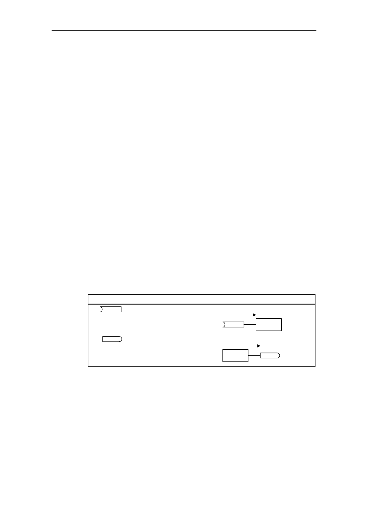
3 Functions Issue 10/06
3.1.2.3 BICO technology
Using BICO technology (English: Binector Connector Technology), process data
can be freely interconnected using the "standard" drive parameterization. In this
case, all values which can be freely interconnected (e.g. frequency setpoint,
frequency actual value, current actual value, etc.) can be defined as "Connectors"
and all digital signals which can be freely interconnected (e.g. status of a digital
input, ON/OFF, message function when a limit is violated etc.) can be defined as
"Binectors".
There are many input and output quantities as well as quantities within the closedloop control which can be interconnected in a drive unit. It is possible to adapt the
drive to the various requirements using BICO technology.
A binector is a digital (binary) signal without any units and which can either have
the value 0 or 1. Binectors always refer to functions whereby they are sub-divided
into binector inputs and binector outputs (refer to Fig. 3-4). In this case, the
binector input is always designated using a "P" parameter with attribute "BI" (e.g.:
P0731 BI: Function, digital output 1), while the binector output is always
represented using an "r" parameter with attribute "BO" (e.g.: r0751 BO: ADC status
word).
As can be seen from the examples above, the binector parameters have the
following abbreviations in front of the parameter names:
¾
BI Binector Input, signal receiver ("P" parameters)
→ The BI parameter can be interconnected with a binector output as source, by
entering the parameter number of the binector output (BO parameter) as
value in the BI parameter (e.g.: Interconnecting the "BO" parameter r0751
with "BI" parameter P0731 → P0731 = 751).
¾
BO Binector Output, signal source ("r" pa rameters)
→ The BO parameter can be used as source for BI parameters. For the
particular interconnection the BO parameter number must be entered into
the BI parameter (e.g.: Interconnecting the "BO" parameter r0751 with "BI"
parameter P0731 → P0731 = 751).
Abbreviation and symbol Name Function
BI
BO
Fig. 3-4 Binectors
Binector input
(signal receiver)
Binector output
(signal source)
Pxxxx
BI: ...
Function
Data flow
Data flow
Function
rxxxx
BO: ...
A connector is a value (16 or 32 bit), which can include a normalized quantity
(without dimension) as well as also a quantity with associated units. Connectors
always refer to functions whereby they are sub-divided into connector inputs and
connector outputs (refer to Fig. 3-5). Essentially the same as the binectors, the
connector inputs are characterized by a "P" parameter with attribute "CI" (e.g.:
P0771 CI: D/A converter); while the connector outputs are always represented
using an "r" parameter with attribute "CO" (e.g.: r0021 CO: Smoothed output
frequency).
MICROMASTER 440 Operating Instructions
60 6SE6400-5AW00-0BP0
Page 61

Issue 10/06 3 Functions
As can be seen from the examples above, connector parameters have the
following abbreviations in front of the parameter names:
CI Connector Input, signal sink ("P" parameters)
¾
→ The CI parameter can be interconnected with a connector output as source,
by entering the parameter number of the connector output (CO parameter)
as value in the CI parameter (e.g.: P0771 = 21).
CO Connector Output, signal source ("r" parame ters)
¾
→ The CO parameter can be used as source for CI parameters. For the
particular interconnection, the CO parameter number must be entered in the
CI parameter (e.g.: P0771 = 21).
Further, MICROMASTER has "r" parameters where several binector outputs are
combined in a word (e.g.: r0052 CO/BO: Status word 1). This feature reduces, on
one hand, the number of parameters and simplifies parameterization via the serial
interface (data transfer). This parameter is further characterized by the fact that it
does not have any units and each bit represents a digital (binary) signal.
As can be seen from the examples of parameters, these combined parameters
have the following abbreviation in front of the parameter names:
¾
CO/BO Connector Output / Binector Output, signal source ("r"
parameters)
→ CO/BO parameters can be used as source for CI parameters and BI
parameters:
a) In order to interconnect all of the CO/BO parameters, the parameter
number must be entered into the appropriate CI parameter (e.g.:
P2016[0] = 52).
b) When interconnecting a single digital signal, in addition to the CO/BO
parameter number, the bit number must also be entered into the BI
parameter (e.g.: P0731 = 52.3)
Abbreviation and symbol Name Function
CI
CO
CO
BO
Fig. 3-5 Connectors
Connector input
(signal receiver)
Connector output
(signal source)
Binector/connector
output
(signal source)
Data flow
Pxxxx
CI: ...
Function
Functions
Function
Data flow
Data flow
CO/BO: ...
rxxxx
CO: ...
rxxxx
In order to interconnect two signals, a BICO setting parameter (signal receiver)
must be assigned the required BICO monitoring parameter (signal source). A
typical BICO interconnection is shown using the following examples (refer to Fig.
3-6).
MICROMASTER 440 Operating Instructions
6SE6400-5AW00-0BP0
61
Page 62
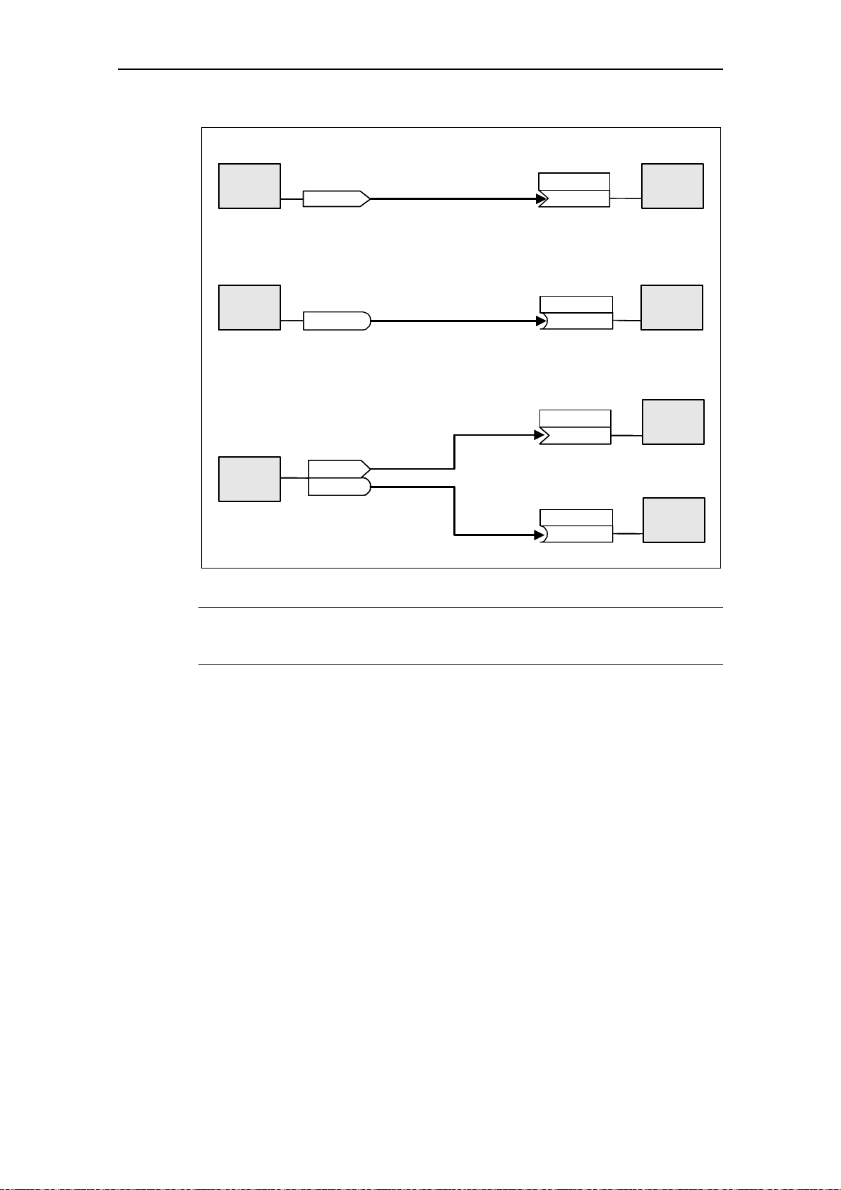
3 Functions Issue 10/06
Connector output (CO) ===> Connector input (CI)
CI: Main setpoint
Function
FB
CO: Act. ADC after scal. [4000h]
r0755
P1070
(755)
Function
P1070 = 755
Binector output (BO) ===> Binector input (BI)
BI: ON/OFF1
P0840
Function
FB
BO: Status word of ADC
r0751
P0840
P0840
(751:0)
(751:0)
(751:0)
Function
FB
P0840 = 751.0
Connector output / Binector output (CO/BO)
P2051 = 52
CO/BO: Act. status word 1
FB
Function
r0052
r0052
BI: Function of digital output 1
CI: PZD to CB
P2051
(52)
P0731FBP0731
P0731
(52:3)
Function
FB
Function
P0731 = 52.3
Fig. 3-6 BICO connections (examples)
NOTE
BICO parameters with the CO, BO or CO/BO attributes can be used a multiple
number of times.
MICROMASTER 440 Operating Instructions
62 6SE6400-5AW00-0BP0
Page 63
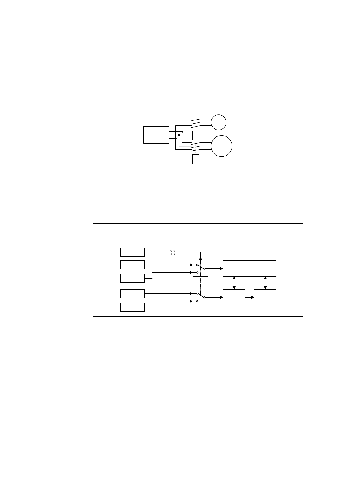
Issue 10/06 3 Functions
3.1.3 Data sets
For many applications it is advantageous if several parameters can be
simultaneously changed, during operation or in the ready state, using an external
signal.
Examples:
¾ The drive inverter should be switched-over from motor 1 to motor 2.
Motor 1
Motor 2
MM4
M1
K1
M2
K2
Fig. 3-7 Example: Changeover from motor 1 to motor 2
¾ The control source (e.g. terminal → BOP) or setpoint (frequency) source (e.g.
ADC → MOP) should be changed-over using a terminal signal (e.g. DIN4) as
function of an external event (e.g. the higher-level control unit fails). A typical
example in this case is a mixer, which may not come to an uncontrolled stop
when the control fails.
Control source: Terminal → BOP
Setpoint (frequency source): ADC → MOP
DIN4
Terminals
BOP
ADC
MOP
P0810 = 722.3
P0700[0] = 2
P0700[1] = 1
P1000[0] = 2
P1000[1] = 1
0
1
0
1
Sequence control
Setpoint
channel
Motor
control
Fig. 3-8 Example: Changing-over between the control and setpoint (frequency)
source
This functionality can be elegantly implemented using indexed parameters (refer to
Section 3.1.1). In this case, as far as the functionality is concerned, the parameters
are combined to form groups / data sets and are indexed. By using indexing,
several different settings can be saved for each parameter which can be activated
by changing-over the data set (i.e. toggling between data sets).
The following data sets apply:
CDS Command Data Set
DDS Drive Data Set
MICROMASTER 440 Operating Instructions
6SE6400-5AW00-0BP0
63
Page 64

3 Functions Issue 10/06
3 independent settings are possible for each data set. These settings can be made
using the index of the particular parameter:
CDS1 ... CDS3
DDS1 ... DDS3
Those parameters (connector and binector inputs) which are used to control the
drive and enter a setpoint, are assigned to the command data set (CDS). The
signal sources for the control commands and setpoints are interconnected using
BICO technology (refer to Section 3.1.2.3). In this case, the connector and binector
inputs are assigned as signal sources corresponding to the connector and binector
outputs. A command data set includes:
¾
Command sources and binector inputs for control commands (digital
signals) e.g.:
♦ Selects the command source P0700
♦ ON/OFF1 P0840
♦ OFF2 P0844
♦ Enable JOG right P1055
♦ Enable JOG left P1056
Setpoint sources and connector inputs for setpoints (analog signals) e.g.:
¾
♦ Selection of frequency setpoint P1000
♦ Selection of main setpoint P1070
♦ Selection of additional setpoint P1075
The parameters, combined in a command data set, are designated with [x] in the
parameter list in the index field.
Index:
st
Pxxxx[0] : 1
Pxxxx[1] : 2
Pxxxx[2] : 3
command data set (CDS)
nd
command data set (CDS)
rd
command data set (CDS)
NOTE
A complete list of all of the CDS parameters can be taken from the parameter list.
It is possible to parameterize up to three command data sets. This makes it easier
to toggle between various pre-configured signal sources by selecting the
appropriate command data set. A frequent application involves, for example, the
ability to toggle between automatic and manual operation.
MICROMASTER has an integrated copy function which is used to transfer
command data sets. This can be used to copy CDS parameters corresponding to
the particular application. The copy operation is controlled with P0809 as follows
(refer to Fig. 3-9):
1. P0809[0] = Number of the command data set which is to be copied (source)
2. P0809[1] = Number of the command data set into which data is to be copied
(target)
3. P0809[2] = 1 → Copying is started
Copying has been completed, if P0809[2] = 0.
MICROMASTER 440 Operating Instructions
64 6SE6400-5AW00-0BP0
Page 65

Issue 10/06 3 Functions
P0809[0] = 0
P0809[1] = 2
P0809[2] = 1
1. CDS
3. CDS
Start copy
P0700
P0701
P0702
P0703
P0704
.
.
.
.
.
P2253
P2254
P2264
[0] [1] [2]
.
.
.
.
.
1. CDS
.
.
.
.
.
2. CDS
.
.
.
.
.
3. CDS
Fig. 3-9 Copying from CDS
The command data sets are changed-over using the BICO parameter P0810 and
P0811, whereby the active command data set is displayed in parameter r0050
(refer to Fig. 3-10). Changeover is possible both in the "Read" as well as in the
"Run" states.
Selection of CDS
BI: CDS bit 1
P0811
(0:0)
BI: CDS b0 loc/rem
P0810
(0:0)
CDS active
r0050
3
2
1
Switch-over time
aprox. 4 ms
3
Switch-over time
aprox. 4 ms
CO/BO: Act CtrlWd2
r0055
.15
r0055
.15
CO/BO: Act CtrlWd1
r0054
.15
r0054
t0
.15
2
1
Fig. 3-10 Changing-over CDS
t0
MICROMASTER 440 Operating Instructions
6SE6400-5AW00-0BP0
65
Page 66

3 Functions Issue 10/06
The drive data set (DDS) contains various setting parameters which are of
significance for the open-loop and closed-loop control of a drive:
¾ Motor and encoder data, e.g.:
♦ Select motor type P0300
♦ Rated motor voltage P0304
♦ Main inductance P0360
♦ Select encoder type P0400
¾ Various closed-loop control parameters, e.g.:
♦ Fixed frequency 1 P1001
♦ Min. frequency P1080
♦ Ramp-up time P1120
♦ Control mode P1300
The parameters, combined in a drive data set, are designated with an [x] in the
parameter list in the index field:
st
Pxxxx[0] : 1
Pxxxx[1] : 2
Pxxxx[2] : 3
drive data set (DDS)
nd
drive data set (DDS)
rd
drive data set (DDS)
NOTE
A complete list of all of the DDS parameters can be taken from the parameter list.
It is possible to parameterize several drive data sets. This makes it easier to toggle
between various drive configurations (control mode, control data, motors) by
selecting the appropriate drive data set.
Just like the command data sets, it is possible to copy drive data sets within the
MICROMASTER. P0819 is used to control the copy operation as follows:
1. P0819[0] = Number of the drive data set which is to be copied (source)
2. P0819[1] = Number of the drive data set into which data is to be copied
(target)
3. P0819[2] = 1
→ Copying is started
Copying has been completed, if P0819[2] = 0.
P0819[0] = 0
P0819[1] = 2
P0819[2] = 1
1. DDS
3. DDS
Start copy
P0005
P0291
P0300
P0304
P0305
.
.
.
.
.
P2484
P2487
P2488
[0] [1] [2]
.
.
.
.
.
1. DDS
.
.
.
.
.
2. DDS
.
.
.
.
.
3. DDS
Fig. 3-11 Copying from DDS
Drive data sets are changed-over using the BICO parameter P0820 and P0821
whereby the active drive data set is displayed in parameter r0051 (refer to Fig.
MICROMASTER 440 Operating Instructions
66 6SE6400-5AW00-0BP0
Page 67

Issue 10/06 3 Functions
3-12). Drive data sets can only be changed-over in the "Ready" state and this takes
approx. 50 ms.
Drive running
Drive ready
t
Selection of DDS
BI: DDS bit 1
P0821
BI: DDS bit 0
P0820
DDS active
r0051[1]
(0:0)
(0:0)
3
2
1
Switch-over timeSwitch-over time
aprox. 50 ms aprox. 50 ms
3
2
CO/BO: Act CtrlWd2
r0055
.05
r0055
.05
CO/BO: Act CtrlWd2
r0055
.04
r0055
.04
t0
1
Fig. 3-12 Changing-over DDS
t0
MICROMASTER 440 Operating Instructions
6SE6400-5AW00-0BP0
67
Page 68

3 Functions Issue 10/06
3.1.4 Reference quantities
Parameter range: P2000 – r2004
Physical quantities are normalized or de-normalized by the frequency inverter
when data is output or is being entered. This conversion is undertaken by the
particular interface using the reference quantities. The normalization / denormalization is carried-out for the following interfaces:
Table 3-5 Normalized interfaces
Interafce 100 %
Analog input
Current input
Voltage input
Analog output
Current output
Voltage output
USS 4000 h
CB 4000 h
Further, for a BICO connection, a normalization is carried-out if the connector
output (CO) represents a physical quantity and the connector input (CI) a
normalized (percentage) quantity (e.g. PID controller). De-normalization is carriedout if the inverse situation exists. This normalization / de-normalization should be
carefully taken into consideration, especially for the free function blocks (FFBs).
Reference quantities (normalization quantities) are intended to allow setpoint and
actual value signals to be represented in a standard fashion (normalization / denormalization of physical quantities such as setpoint and actual frequency). This
also applies for permanently set parameters that are entered as a "percentage". A
value of 100 % corresponds to a process data value PZD of 4000 h (USS or CB) –
or a current / voltage value of 20 mA / 10 V (analog input / output). The following
reference parameters and permanently saved reference values are available:
20 mA
10 V
20 mA
10 V
Table 3-6 Normalization functions
Parameter Designation Value (100 % / 4000 h) Units
P2000 Reference frequency P2000 Hz
P2001 Reference voltage P2001 V
P2002 Reference current P2002 A
P2003 Reference torque P2003 Nm
r2004 Reference power
- Reference speed
- Reference temperature 100 °C °C
- Reference energy 100 kWh kWh
π * P2000 * P2003
P2000 * 60 / r0313
kW
RPM
MICROMASTER 440 Operating Instructions
68 6SE6400-5AW00-0BP0
Page 69

Issue 10/06 3 Functions
Example
Using the reference frequency P2000 as example, normalization / de-normalization
is demonstrated via the serial interface "USS at BOP link".
If the connection between two BICO parameters is closed (directly using the BICO
parameters or indirectly using P0719 or P1000), that have different representation
types (normalized representation (hex) or physical representation (Hz)), then in the
frequency inverter, the following normalization is made to the target value:
P2016
r0021
x[Hz] y[Hex]
[0]
[1]
[2]
[3]
USS-PZD
BOP link
r0021[Hz]
y[Hex] ⋅=
P2000[Hz]
]Hex[4000
r2015
USS-PZD
BOP link
x[Hex]
Fig. 3-13 Normalization / de-normalization
[0]
[1]
[2]
[3]
P1070
y[Hz]
r2015[1]
y[Hz] ⋅=
4000[Hex]
2000P
Note
¾ Analog values are limited to 10 V or 20 mA. A maximum of 100 % referred to
the corresponding reference values can be output / entered as long as no
DAC/ADC scaling is made (factory setting).
¾ Setpoints and actual value signals via serial interface:
♦ When transferring using the PZD part, they are limited to the value 7FFF h.
This is the reason that the maximum value is 200 % referred to the reference
value.
♦ When transferring data using the PKW part, they are transferred dependant
on the data type and the units.
¾ Parameter P1082 (max. frequency) limits the frequency in the frequency
inverter independent of the reference frequency. When changing P1082
(factory setting: 50 Hz), this is the reason that P2000 should always be
adapted (factory setting: 50 Hz). If, e.g. for a NEMA motor, the parameter is set
to 60 Hz, and no changes are made regarding P2000, then the analog setpoint
/ actual value is limited to 100 % or a setpoint / actual value signal at 4000 h is
limited to 50 Hz!
MICROMASTER 440 Operating Instructions
6SE6400-5AW00-0BP0
69
Page 70

3 Functions Issue 10/06
3.2 Operator panels for MICROMASTER
MICROMASTER drive units can be optionally equipped with a BOP (Basic
Operator Panel) or AOP (Advanced Operator Panel). The AOP distinguishes itself
as a result of a plain text display which simplifies operator control, diagnostics as
well as also commissioning (start-up).
BOP AOP
Fig. 3-14 Operator panels
3.2.1 Description of the BOP (Basic Operator Panel)
The BOP, available as option, allows drive inverter parameters to be accessed. In
this case, the Status Display Panel (SDP) must be removed and the BOP either
inserted or connected in the door of a cabinet using a special mounting kit
(Operator panel door mounting set) (refer to the Attachment A).
Parameter values can be changed using the BOP. This allows the
MICROMASTER drive unit to be set-up for a particular application. In addition to
the keys (refer to Section 3.2.3), it includes a 5-digit LCD display on which the
parameter numbers rxxxx and Pxxxx, parameter values, parameter units (e.g. [A],
[V], [Hz], [s]), alarm Axxxx or fault messages Fxxxx as well as setpoints and actual
values.
NOTE
¾ Contrary to the AOP, for the BOP, parameters do not have to be set or taken
into consideration when establishing the communications between the BOP and
drive inverter.
¾ A BOP does not have a local memory. This means that it is not possible to save
a parameter set on the BOP.
MICROMASTER 440 Operating Instructions
70 6SE6400-5AW00-0BP0
Page 71

Issue 10/06 3 Functions
3.2.2 Description of the AOP (Advanced Operator Panel)
An AOP (this is available as option) has the following additional functions with
respect to a BOP:
¾ Multi-language and multi-line plain text display
¾ Units are additionally displayed, such as [Nm], [°C], etc.
¾ Active parameters, fault messages, etc. are explained
¾ Diagnostics menu to support troubleshooting
¾ The main menu is directly called by simultaneously pressing keys Fn and P
¾ Timer with 3 switching operations per entry
¾ Up to 10 parameter sets can be downloaded / saved
¾ Communications between an AOP and MICROMASTER are realized using the
USS protocol. An AOP can be connected to the BOP link (RS 232) as well as to
the COM link interface (RS 485) of the drive inverter.
¾ Multi-point capable coupling to control (open-loop) and visualize up to 31
MICROMASTER drive inverters. The USS bus must, in this case, be configured
and parameterized via the drive inverter terminals of the COM link interface.
Please refer to Sections 3.2.3, 3.2.4 and the AOP Manual for additional details.
NOTE
¾ Contrary to the BOP, for the AOP, the communications parameters of the
particular interface must be taken into account.
¾ When inserting / connecting to the drive inverter, the AOP automatically
changes the parameter P2012 (USS-PZD length) to 4 corresponding to the
interface.
COM link: P2012[0]
BOP link: P2012[1]
¾ For DriveMonitor, the default value for the USS-PZD length is set to 2. This
results in a conflict if the AOP and the DriveMonitor are operated, alternating, at
the same interface.
Remedy: Increase the USS-PZD length to 4.
MICROMASTER 440 Operating Instructions
6SE6400-5AW00-0BP0
71
Page 72

3 Functions Issue 10/06
3.2.3 Keys and their functions on the operator panel (BOP / AOP)
Operator
panel/key
Function Effects
Start motor
Stop motor
Direction
Functions
Parameter
Increase
Status
display
reversal
Jog
motor
access
value
Reduce
value
The LCD indicates the settings which the drive inverter is presently using.
The drive inverter is started by pressing the key. This key is de-activated in the
default setting. Parameter P0700 or P0719 should be changed as follows to
activate the key:
BOP: P0700 = 1 or P0719 = 10 ... 16
AOP: P0700 = 4 or P0719 = 40 .... 46 on the BOP link
P0700 = 5 or P0719 = 50 .... 56 on the COM link
OFF1 When this key is pressed, the motor comes to a standstill within the
selected ramp-down time. It is de-activated in the default setting; to
activate → refer to the "Start motor" key.
OFF2 The motor coasts down to a standstill by pressing the key twice (or
pressing once for a longer period of time). This function is always
activated.
To reverse the direction of rotation of the motor, press this key. The opposing
direction is displayed using the minus character (-) or by the flashing decimal
point. In the default setting this function is de-activated; to activate it → refer to
the "Start motor" key.
In the "Ready to power-on" state, when this key is pressed, the motor starts and
rotates with the pre-set jog frequency. The motor stops when the key is
released. When the motor is rotating, this key has no effect.
This key can be used to display additional information.
If you press the key during operation, independent of the particular parameter,
for two seconds, then the following data is displayed:
1. Voltage of the DC current link (designated by d – units V).
2. Output current (A)
3. Output frequency (Hz)
4. Output voltage (designated by o – units V).
5. The value, selected in P0005 (if P0005 is configured so that one of the
above pieces of data is displayed (1 to 4), then the associated value is not
re-displayed).
The displays mentioned above are run-through one after the other by pressing
again.
Step function
Starting from any parameter (rXXXX or PXXXX), if the key Fn is briefly pressed,
then a jump is immediately made to r0000. You can then, when required,
change an additional parameter. After returning to r0000, when key Fn is
pressed, then the system returns to the starting point.
Acknowledgement
If alarm and fault messages are present, then these can be acknowledged by
pressing key Fn.
Parameters can be accessed by pressing this key.
When this key is pressed, the displayed value is increased.
When this key is pressed, the displayed value is decreased.
AOP menu
Calls the AOP menu prompting (this is only available for AOP).
+
Fig. 3-15 Operator panel keys
MICROMASTER 440 Operating Instructions
72 6SE6400-5AW00-0BP0
Page 73

Issue 10/06 3 Functions
3.2.4 Changing parameters using the operator panel
The way that parameter P0719 can be changed will now be described; please use
this description as a basis when setting all of the other parameters using the BOP.
Changing P0004 – parameter filter function
Step
1
Press in order to access the parameter
2
Press until P0004 is displayed
Press in order to reach the parameter value
3
level
Press or
4
required value
Press to acknowledge the value and to save
5
the value
The user can only see the command parameters.
6
in order to obtain the
Result on the display
Changing an indexed parameter P0719 – selecting the command/frequency
setpoint
Step
1
Press in order to access the parameter
2
Press until P0719 is displayed
Result on the display
3
Press in order to reach the parameter value
Press in order to display the currently set
4
value
Press or in order to obtain the required
5
value
Press to acknowledge the value and to save
6
the value
7
Press until r0000 is displayed
Press in order to return to the operating
8
display (the display which the customer has
defined)
Fig. 3-16 Changing parameters using the BOP
NOTE
The BOP sometimes display when changing parameter values. This
means that the drive inverter is presently handling another higher-priority task.
MICROMASTER 440 Operating Instructions
6SE6400-5AW00-0BP0
73
Page 74
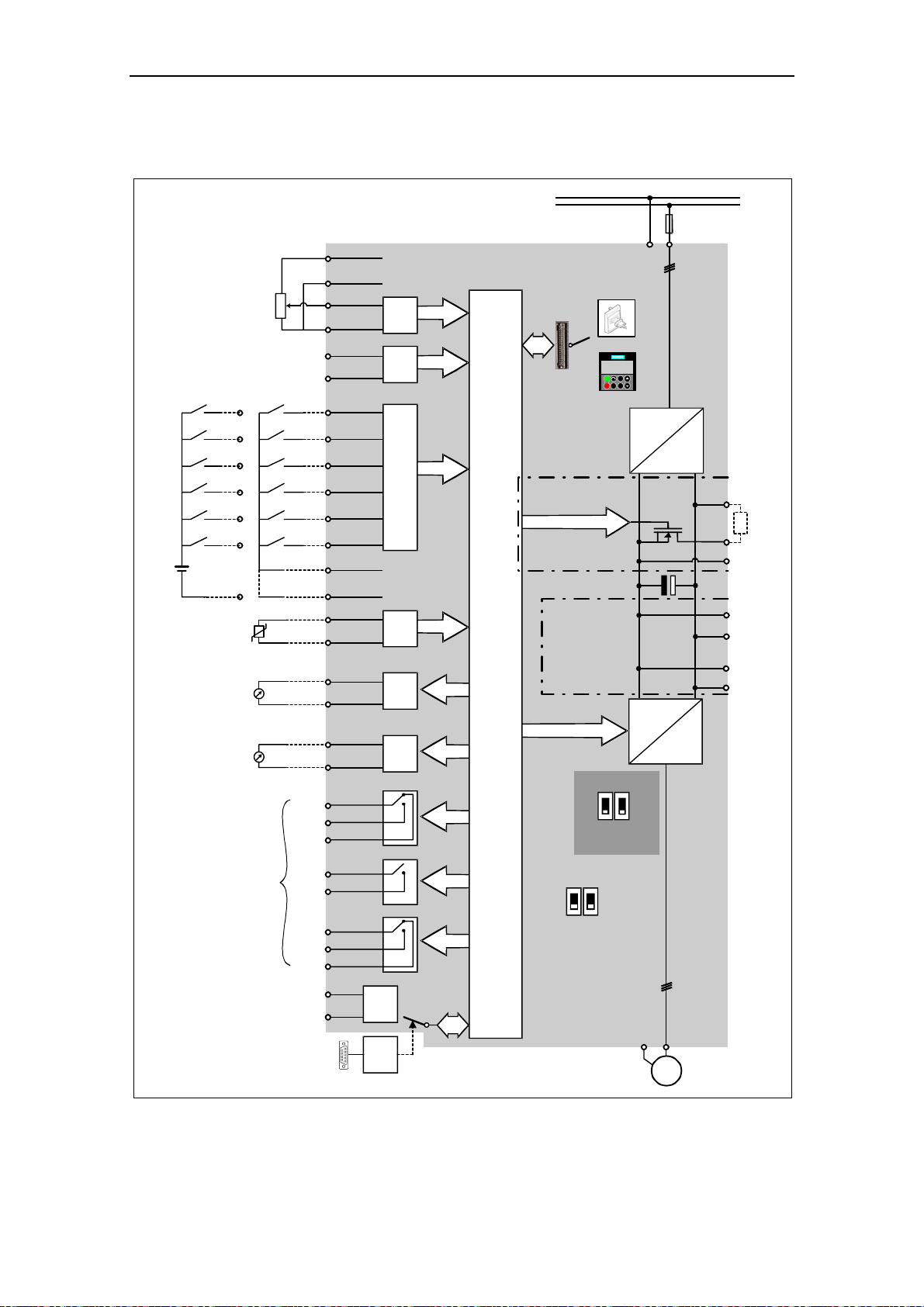
3 Functions Issue 10/06
3.3 Block diagram
PE
≥ 4.7 kΩ
External 24 V
DIN1
5
DIN2
6
DIN3
7
DIN4
8
DIN5
16
DIN6
Motor
PTC
KTY84
0 - 20 mA
max. 500 Ω
0 - 20 mA
max. 500 Ω
17
PNP
or
NPN
28
+
24 V
_
30 V DC / 5 A (resistive)
250 V AC / 2 A (inductive)
Relay1
Relay2
Relay3
1
2
3
4
10
11
5
6
7
8
16
17
9
28
14
15
12
13
26
27
20
19
18
22
21
25
24
23
29
30
ADC1+
ADC1-
ADC2+
ADC2-
DIN1
DIN2
DIN3
DIN4
DIN5
DIN6
PTCA
PTCB
DAC1+
DAC1-
DAC2+
DAC2-
COM
NO
NC
COM
NO
COM
NO
NC
P+
N-
+10 V
0 V
Output +24 V
max. 100 mA
(isolated)
Output 0 V
max. 100 mA
(isolated)
RS485
CB
Option
A/D
A/D
Opto Isolation
A/D
D/A
D/A
COM link
automatic
CPU
1/3 AC 200 - 240 V
3 AC 380 - 480 V
3 AC 500 - 600 V
BOP link
Frame sizes
A to F
Frame sizes
FX and GX
ADC1ADC
0 - 20 mA
current
0 - 10 V
voltage
12
RS232
150.00
Hz
Fn
I
Jog
P
0
BOP/AOP
Not
used
12
DIP switch
(on Control Board)
2
DIP switch
(on I/O Board)
=
60 Hz
50 Hz
PE
PE
~
SI
L/L1, N/L2
or
L/L1, N/L2,L3
or
L1, L2, L3
=
3 ~
U,V,W
M
DC-
DCNA
DCPA
DCNS
DCPS
B+/DC+
B-
R
External braking
Connection for
module connection
dv/dt filter
Fig. 3-17 MICROMASTER 440 – block diagram
MICROMASTER 440 Operating Instructions
74 6SE6400-5AW00-0BP0
Page 75

Issue 10/06 3 Functions
3.4 Factory setting
The MICROMASTER drive unit is shipped from the
plant with a Status Display Panel (SDP, refer to Fig.
3-18). The SDP has two LEDs on the front panel
which display the operating state of the drive inverter
(refer to Section 4.1).
When MICROMASTER is shipped from the plant with
the SDP functioning, it can be operated without any
additional parameterization. In this case, the drive
inverter default settings (which depend on the drive
inverter type / size) match the following data of a 4pole motor:
¾ Rated motor power P0307
Fig. 3-18 Status Display
Panel (SDP)
¾ Rated motor voltage P0304
¾ Rated motor current P0305
¾ Rated motor frequency P0310
(We recommend a Siemens standard motor.)
Further, the following conditions must be fulfilled:
¾ Control (ON/OFF command) via digital inputs (refer to Table 3-7)
¾ Setpoint input via analog input 1 P1000 = 2
¾ Induction motor P0300 = 1
¾ Self-cooled motor P0335 = 0
¾ Motor overload factor P0640 = 150 %
¾ Min. frequency P1080 = 0 Hz
¾ Max. frequency P1082 = 50 Hz
¾ Ramp-up time P1120 = 10 s
¾ Ramp-down time P1121 = 10 s
¾ Linear V/f characteristic P1300 = 0
Table 3-7 Pre-assignment of the digital inputs
Digital inputs Terminals Parameter Function Active
Command source - P0700 = 2 Terminal strip Yes
Digital input 1 5 P0701 = 1 ON / OFF1 Yes
Digital input 2 6 P0702 = 12 Reversing Yes
Digital input 3 7 P0703 = 9 Fault acknowledge Yes
Digital input 4 8 P0704 = 15 Fixed setpoint (direct) No
Digital input 5 16 P0705 = 15 Fixed setpoint (direct) No
Digital input 6 17 P0706 = 15 Fixed setpoint (direct) No
Digital input 7 Via ADC1 P0707 = 0 Digital input disabled No
Digital input 8 Via ADC2 P0708 = 0 Digital input disabled No
MICROMASTER 440 Operating Instructions
6SE6400-5AW00-0BP0
75
Page 76

3 Functions Issue 10/06
If the various prerequisites are fulfilled and the appropriate conditions present, then
after the motor has been connected and the power connected, then the following is
possible with the factory setting:
¾ The motor can be started and stopped (via DIN1 with external switch)
¾ The direction of rotation can be reversed (via DIN2 with external switch)
¾ Faults reset (via DIN3 with external switch)
¾ A frequency setpoint can be entered (via ADC1 with external
potentiometer
default setting of the ADC:
Voltage input)
¾ The frequency actual value can be output (via D/A converter, D/A converter
output: current output)
The potentiometer and the external switches can be connected through the drive
inverter internal power supply, as shown in Fig. 3-19.
Analog output
Pre-assignment of the digital inputs DIN1 to DIN3, refer to Table 3-7.
Fig. 3-19 Recommended wiring for the factory setting
If settings have to be made which go beyond the factory setting, then depending on
the complexity of the application, when commissioning the drive system, the
particular function description as well as the parameter list including function charts
must be carefully taken into consideration.
MICROMASTER 440 Operating Instructions
76 6SE6400-5AW00-0BP0
Page 77
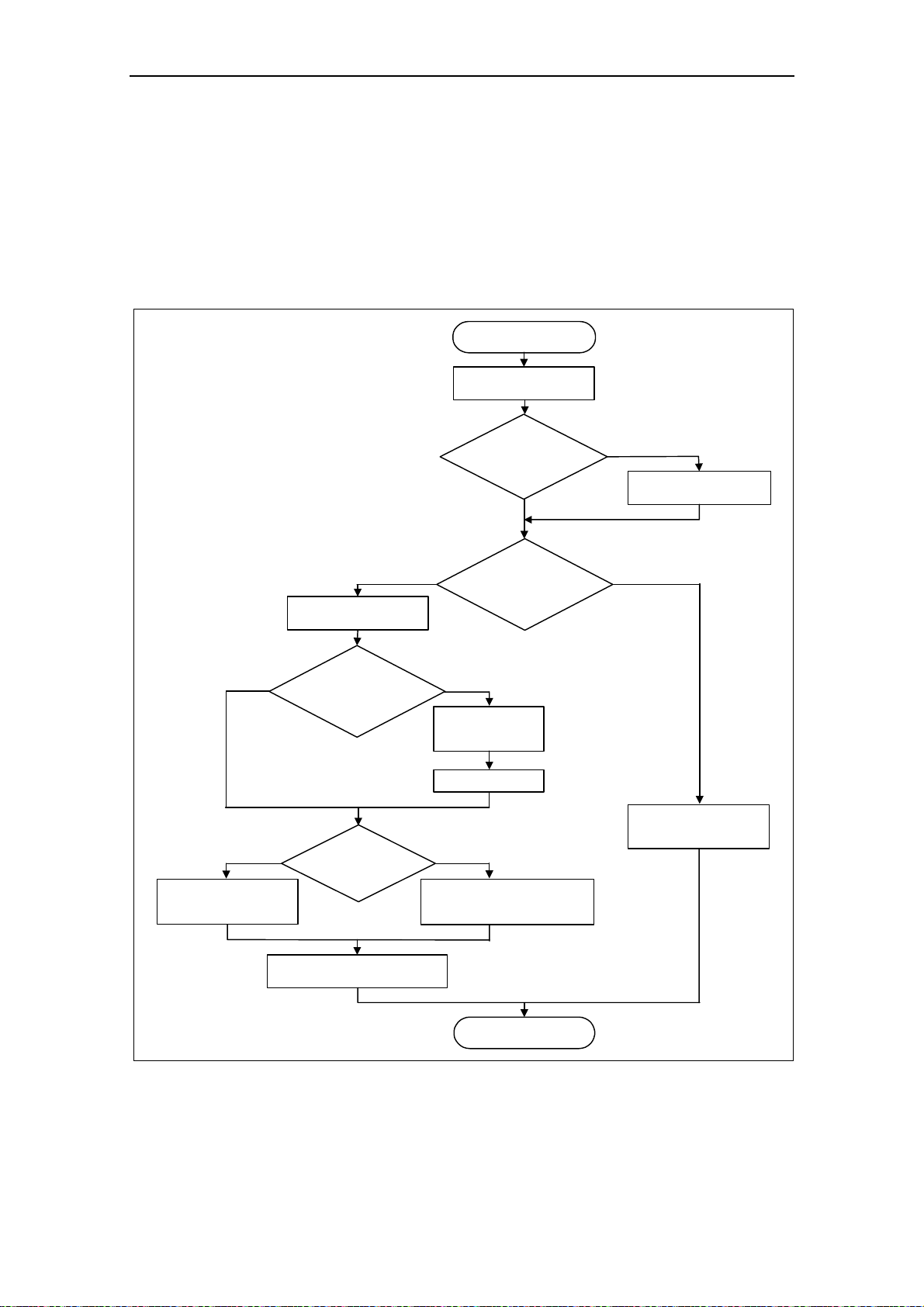
Issue 10/06 3 Functions
3.5 Commissioning
A differentiation is made between the following scenarios when commissioning
MICROMASTER:
¾ 50/60 Hz changeover ¾ Quick commissioning
¾ Motor data identification ¾ Calculating the motor / control data
¾ Series commissioning ¾ Commissioning the application
Start commissioning
Carry-out checklist
no
no
Motor data identification
Section 3.5.5
Quick commissioning
Section 3.5.3
Is the moment
of inertia of the motor
and load known
?
Motor
equivalent
circuit diagram data
known
?
NEMA motor
60 Hz / hp ?
Section 3.5.2
Complete
no
parameter list
of a commissioning
yes
P0341 = ?
P0342 = ?
P0344 = ?
P0340 = 1
yes
Enter motor equivalent
circuit diagram data
Section 3.5.4
yes
50/60 Hz setting
Section 3.5.1
no
yes
available
?
Series commissioning
Section 3.5.7
Commissioning the application
Section 3.5.6
End of commissioning
Fig. 3-20 Procedure when commissioning
MICROMASTER 440 Operating Instructions
6SE6400-5AW00-0BP0
77
Page 78

3 Functions Issue 10/06
When commissioning, initially, a quick or series commissioning should be carriedout. The actual application should only be commissioned if the drive inverter –
motor combination provides a satisfactory result.
If the drive is to be commissioned from a defined state, then the drive inverter can
be reset to the initial state when it left the plant. This is done as follows:
¾ Reset parameters to the factory setting
Check list
The following check list should help you to commission MICROMASTER without
any problems and to guarantee a high degree of availability:
¾ When handling the drive unit, carefully observe all of the ESD measures.
¾ All of the screws must have been tightened up to their specified torque.
¾ All connectors / option modules must have been correctly inserted and locked /
screwed into place.
¾ The DC link pre-charging has been completed.
¾ All of the components are grounded/earthed at the points provided and all of the
shields have been connected.
¾ MICROMASTER drive units have been designed for defined mechanical,
climatic and electrical ambient conditions. It is not permissible that the specified
limit values are exceeded in operation and when the drive units are being
transported. The following must be especially carefully observed:
♦ Line supply conditions
♦ Pollutant stressing
♦ Gases which can have a negative impact on the function
♦ Ambient climatic conditions
♦ Storage / transport
♦ Shock stressing
♦ Vibration stressing
♦ Ambient temperature
♦ Installation altitude
In addition to carrying-out all of the installation work, an important prerequisite for
successful commissioning is that the drive inverter is not disconnected from the line
supply while being parameterized. If a line supply failure interrupts commissioning,
then inconsistencies can occur regarding the parameterization. In this case, it is
important that the commissioning is re-started (possibly reset and establish the
original factory settings (refer to Section 3.5.9)).
NOTE
When using output reactors, the pulse frequency may not be set higher than 4 kHz.
The following parameter setting is mandatory when using an output reactor:
P1800 = 4 kHz , P0290 = 0 or 1
MICROMASTER 440 Operating Instructions
78 6SE6400-5AW00-0BP0
Page 79

Issue 10/06 3 Functions
3.5.1 50/60 Hz setting
The frequency setting made in the factory can be adapted to the North American
market, without requiring any parameterization using an operator panel or PC tool
using the DIP50/60 switch (refer to Fig. 3-21) under the I/O board (refer to the
Appendix C when removing the I/O board).
DIP50/60
Remove I/O board
Fig. 3-21 DIP switch to change-over between 50/60 Hz
The switch determines the value of parameter P0100 corresponding to the
following diagram (refer to Fig. 3-22). Besides P0100 = 2, after the power supply
voltage has been switched-in, the DIP50/60 switch determines the 50/60 Hz setting
(value of parameter P0100).
Power
cycle
P0100 = 2
?
no
DIP2 = OFF
?
yes
yes
no
yes
no
Quick
commissioning
P0010 = 1
P0100 = 2
?
no
P0100 = 1
?
yes
Power in kW
Frequency 50 Hz
P0100 = 0 P0100 = 2 P0100 = 1
Power in kW
Frequency 60 Hz
Power in hp
Frequency 60 Hz
Fig. 3-22 Mode of operation of the DIP50/60 switch in conjunction with P0100
MICROMASTER 440 Operating Instructions
6SE6400-5AW00-0BP0
79
Page 80

3 Functions Issue 10/06
By changing the setting of DIP50/60 switch, after the drive inverter has been
powered-down/powered-up, the parameters for the rated motor frequency P0310,
max. frequency P1082 and reference frequency P2000 are automatically pre-set.
In addition, the rated motor parameters as well as all of the other parameters which
depend on the rated motor parameters, are reset. The units of the power
parameters are, depending on P0100, are either interpreted as kW value or hp
value.
NOTE
Switch DIP2(1) (refer to Fig. 3-21) under the I/O board has no function.
3.5.2 Motor circuit
In order to ensure a straightforward, successful commissioning, it is important that
the circuit connection in the motor terminal box (refer to Fig. 3-23) matches the
rated motor voltage entered in P0304 or the rated motor current P0305.
IEC Motor
W2
U2
V1
V2
W1
W2U1U2V1V2
U1
W1
U1
U1
V1
W1
Delta connection
V1
W1
Star connection
e.g.: Volts 230 V (Delta connection) / 400 V (Star connection)
NEMA Motor
Volts
low
high
UVW
T
1-T7T2-T8T3-T9
T1T2T
e.g.: Volts 230 V YY (low) / 460 V Y (high)
Volts
low
high
UVW
T
1-T6-T7T2-T4-T8T3-T5-T9
T
T
1
Connected
together
T4-T5-T
T
3
1-T7T2-T8T3-T9
T3T4-T7T5-T8T6-T
2
6
Connected
together
-
Connection
Y Y
Y
9
T
Connection
∆ ∆
∆
T
1
T
4
T
7
T
T
9
6
3
T
T
8
T
5
T
2
T
1
T
4
T
9
T
T
7
6
T
3
T5T
8
2
Fig. 3-23 Motor terminal box
MICROMASTER 440 Operating Instructions
80 6SE6400-5AW00-0BP0
Page 81

Issue 10/06 3 Functions
The following must be noted when entering the rating plate data or the ESB data:
¾ The outer conductor voltage/phase-to-phase voltage (voltage U
conductors L1, L2) and the outer conductor current (phase current) I
between outer
12
are
1
always specified on the rating plate.
¾ The rated motor voltage P0304 and the rated motor current P0305 must always
be entered according to the motor circuit configuration (either delta/star circuit
configuration).
¾ If rated motor data that are available (P0304, P0305) are not consistent with the
motor circuit configuration, then an appropriate conversion should be made
which is then entered.
¾ If equivalent circuit diagram data (P0350, P0354, P0356, P0358, P0360) is
available, then these should be entered according to the motor circuit
configuration. If there is no consistency between the motor circuit configuration
and equivalent circuit diagram data, then the equivalent circuit diagram data
should be converted and entered corresponding to the data on the rating plate
(P0304, P0305).
I
1
1
U
12
2
3
U
1N
I
1N
Z
N
ZZ
I
1
1
U
12
2
3
ZZ
I
12
Z
==
III
321
===
UUU
U
12
Z2
⋅=
I
1
U 3
⋅
312312
1Ν
1
=
I
U
Z
I
Y1,∆1,
3
1
=
U
∆12,
=
∆12,
Y12,
3
2
Z
Y12,
3
U
12
3
I
1
1
⋅===
III
==
Z
⋅=
I
1312312
3
UUU
312312
Fig. 3-24 Star / delta circuit configurations
NOTE
The precise equivalent circuit diagram data are of extreme important regarding the
stability of the closed-loop vector control and for the voltage boost applied to the
V/f characteristic. Equivalent circuit diagram data can only be estimated from the
rating plate data; this is the reason that equivalent circuit diagram data is either
determined
- using the motor data identification (refer to Chapter 0), or
- is entered from a motor data sheet that may be available (refer to Chapter 0).
NOTE
The MICROMASTER series of drive units is not available for 3-ph. 690 V AC.
MICROMASTER 440 Operating Instructions
6SE6400-5AW00-0BP0
81
Page 82

3 Functions Issue 10/06
87 Hz characteristic
When a motor with a delta circuit configuration (e. g. V
= 230 V) is fed from a
N∆, motor
frequency inverter, where the rated voltage corresponds to the star circuit
configuration (e.g. 400 V frequency inverter), then it is important to proceed as
follows and observe the following:
¾ The motor must have the appropriate voltage strength.
¾ Above the rated motor frequency, the iron losses in the motor increase over-
proportionally. This is the reason that above this frequency, the thermal motor
torque should be reduced.
¾ For the quick commissioning, the rating plate data for the delta circuit
configuration should be entered or the rating plate must be appropriately
converted.
¾ The drive inverter must be designed for the higher current (delta circuit
configuration).
¾ The 87 Hz characteristic is independent of the control type and can therefore be
used both for V/f control as well as for closed-loop vector control.
¾ When using the 87 Hz characteristic, the mechanical motor limits must be taken
into account (refer to Catalog M11).
For the 87 Hz characteristic, the ratio between the voltage and frequency (V/f
characteristic) remain constant. This is the reason that the following relationships
apply:
U
(400 V)
U
(230 V)
U
N1
N∆
f
N∆
f
(50 Hz) (87 Hz)
N1
f
U
N1
P
N1
U
N∆
U
N1
f
N1
U
N∆
60
+−
=
n
N1
⋅=
P
N∆
⋅=
f
N∆
s
⎤
⎡
⎥
⎢
min
⎦
⎣
()
p
n
ff
N∆N1
P = power
f = frequency
n = speed
p = pole pair No.
∆
Fig. 3-25 V/f characteristic
Table 3-8 Example 1LA7060-4AB10
Delta circuit
P0304 Rated motor voltage 230 V 400 V 400 V
P0305 Rated motor current 0.73 A 0.73 A 0.42 A
P0307 Rated motor power 120 W 207 W 120 W
P0308
P0310 Rated motor frequency 50 Hz 87 Hz 50 Hz
P0311 Rated motor speed 1350 RPM 2460 RPM 1350 RPM
P0314 Motor pole pairs 2 2 2
Cos ϕ
configuration
0.75 0.75 0.75
87 Hz
characteristic
Star circuit
configuration
Contrary to the BOP, AOP operator panels or the commissioning program DriveMonitor, the STARTER commissioning (start-up) program offers a mask-orientated
quick commissioning, which is especially advantageous for users who are using
MICROMASTER for the first time. On the other hand, BOP, AOP and DriveMonitor
offer, in conjunction with the drive inverter, parameter-orientated quick commissioning where the user is navigated through the menu tree mentioned.
MICROMASTER 440 Operating Instructions
82 6SE6400-5AW00-0BP0
Page 83

Issue 10/06 3 Functions
3.5.3 Quick commissioning
If there is still no appropriate parameter set for the drive, then a quick
commissioning must be carried-out for the closed-loop Vector control and for the
V/f control including a motor data identification routine. The following operator units
can be used to carry-out quick commissioning:
¾ BOP (option)
¾ AOP (option)
¾ PC Tools (with commissioning program STARTER, DriveMonitor)
When the quick commissioning is carried-out, the motor – drive inverter is basically
commissioned; the following data must be obtained before quick commissioning is
started:
¾ Line supply frequency
¾ Motor rating plate data
¾ Command / setpoint sources
¾ Min. / max. frequency or ramp-up / ramp-down time
¾ Closed-loop control mode
¾ Motor data identification
Parameterizing the drive with BOP or AOP
The frequency inverter is adapted to the motor using the quick commissioning
function and important technological parameters are set. The quick commissioning
shouldn't be carried-out if the rated motor data saved in the frequency inverter
(4-pole 1LA Siemens motor, star circuit configuration
specific) match the rating plate data.
Parameters, designated with a * offer more setting possibilities than are actually
listed here. Refer to the parameter list for additional setting possibilities.
NOTE
¾ Parameter P0308 or P0309 can only be viewed on the BOP or AOP if P0003 ≥
2. Depending on the setting of parameter P0100, either P0308 or P0309 is
displayed.
¾ The value entered into P0307 and all of the other power data – depending on
P0100 – are either interpreted as kW or hp value.
START
P0003 = 3
P0004 = 0
Factory setting
User access level *
1 Standard: Allows access into most frequently used parameters
2 Extended: Allows extended access e.g. to inverter I/O functions
3 Expert (For expert use only)
Parameter filter *
0 All parameters
2 Inverter
3 Motor
4 Speed sensor
frequency inverter (FU)-
1
0
MICROMASTER 440 Operating Instructions
6SE6400-5AW00-0BP0
83
Page 84

3 Functions Issue 10/06
P0010 = 1
P0100 =...
P0100 = 1, 2
P0100 = 0
P0205 =...
P0205 =...
P0300 =...
P0300 =...
P0304 =...
P0305 =...
P0307 =...
P0309 =...
P0304 =...
P0305 =...
P0307 =...
P0308 =...P0308 =...
P0309 =...
Commissioning parameter *
0 Ready
1 Quick commissioning
30 Factory setting (refer to Section 3.5.9)
NOTE
P0010 should be set to 1 in order to parameterize the data of the motor rating
plate.
Europe/ North America
(enters the line supply frequency)
0 Europe [kW],
1 North America [hp], frequency default
2 North America [kW], frequency default
frequency default 50 Hz
60 Hz
60 Hz
NOTE
For P0100 = 0 or 1, the setting of switch DIP50/60 determines the value of
P0100 (refer to Section 3.5.1).
OFF = kW, 50 Hz
ON = hp, 60 Hz
Inverter application (enters the required torque)
0 Constant torque (e.g. compressors, processing machines)
1 Variable torque (e.g. pumps, fans)
NOTE
This parameter is only effective for drive inverters ≥ 5.5 kW / 400 V
Select motor type
1 Asynchronous motor (induction motor)
2 Synchronous motor
NOTE
For P0300 = 2 (synchronous motor), only the V/f control types (P1300 < 20) are
permitted.
Rated motor voltage
(Nominal motor voltage [V]
from rating plate)
The rated motor voltage on the rating
plate must be checked, regarding the
star/delta circuit configuration to
ensure that it matches with the circuit
connection configured at the motor
terminal board
Rated motor current
(Nominal motor current [A]
from rating plate)
Rated motor power
(Nominal motor power [kW/hp]
from rating plate)
If P0100 = 0 or 2, value will be in kW.
If P0100 = 1, value will be in in hp.
Rated motor cosPhi
(Nominal motor power factor (cos ϕ) from rating plate)
If the setting is 0, the value is automatically calculated
P0100 = 1,2: P0308 no significance, no entry required.
Rated motor efficiency
(Nominal motor efficiency in [%] from rating plate)
Setting 0 causes internal calculation of value.
P0100 = 0: P0309 no significance, no entry required.
FU-spec.
FU-spec.
FU-spec.
P0304
P0310
P0305
P0307
P0308 P0311
Example of a typical motor rating plate (data for
a delta circuit configuration).
The precise definition and explanation of this
data is specified in DIN EN 60 034-1.
0
0
0
1
FU-spec.
FU-spec.
MICROMASTER 440 Operating Instructions
84 6SE6400-5AW00-0BP0
Page 85

Issue 10/06 3 Functions
P0310 =...
P0311 =...
P0320 = ...
P0335 =...
P0640 =...
P0700 =...
Rated motor frequency
(Nominal motor frequency in [Hz] from rating plate)
Pole pair number recalculated automatically if parameter is changed.
Rated motor speed
(Nominal motor speed in [rpm] from rating plate)
Setting 0 causes internal calculation of value.
NOTE
An entry must
be made for closed-loop Vector control, V/f control with FCC and
for slip compensation.
Motor magnetizing current
(this is entered as a % referred to P0305)
Motor magnetizing current as a % relative to P0305 (rated motor current).
With P0320 = 0, the motor magnetizing current is calculated using P0340 = 1 or
using P3900 = 1 - 3 (end of the quick commissioning) – and is displayed in
parameter r0331.
Motor cooling
(Selects motor cooling system used)
0 Self-cooled: Using shaft mounted fan attached to motor
1 Force-cooled: Using separately powered cooling fan
2 Self-cooled and internal fan
3 Force-cooled and internal fan
Motor overload factor
(Motor overload factor in [%] relative to P0305)
This defines the limit of the maximum output current as a % of the rated motor
current (P0305). This parameter is set, using P0205 for constant torque, to
150 %, and for variable torque, to 110 %.
Selection of command source
(enters the command source)
0 Factory default setting
1 BOP (keypad)
2 Terminal
4 USS on BOP link
5 USS on COM link (control terminals 29 and 30)
6 CB on COM link (CB = communications module)
50.00 Hz
FU-spec.
0.0
0
150 %
2
BOP
Terminals
USS
BOP link
USS
COM link
CB
COM link
P0700 = 2
Sequence control
Setpoint
channel
Motor
control
MICROMASTER 440 Operating Instructions
6SE6400-5AW00-0BP0
85
Page 86
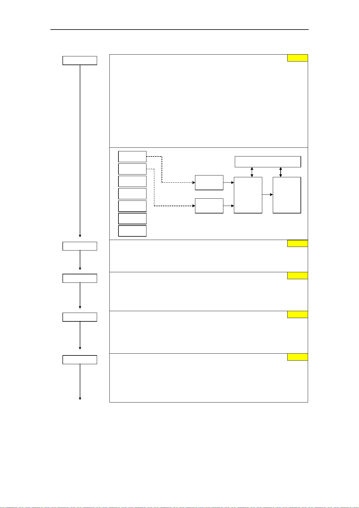
3 Functions Issue 10/06
P1000 =...
P1080 =...
P1082 =...
P1120 =...
P1121 =...
Selection of frequency setpoint *
(enters the frequency setpoint source)
1 MOP setpoint
2
2 Analog setpoint
3 Fixed frequency
4 USS on BOP link
5 USS on COM link (control terminals 29 and 30)
6 CB on COM link (CB = communications module)
10 No main setpoint + MOP setpoint
11 MOP setpoint + MOP setpoint
12 Analog setpoint + MOP setpoint
...
76 CB on COM link + Analog setpoint 2
77 Analog setpoint 2 + Analog setpoint 2
MOP
ADC
FF
USS
BOP link
USS
COM link
CB
COM link
ADC2
P1000 = 12
P1000 = 1
Sequence control
Additonal
setpoint
Setpoint
channel
2
Main
setpoint
Motor
control
Min. frequency
(enters the minimum motor frequency in Hz)
0.00 Hz
Sets minimum motor frequency at which motor will run irrespective of frequency
setpoint. The value set here is valid for both clockwise and anticlockwise rotation.
Max. frequency
(enters the maximum motor frequency in Hz)
50.00 Hz
Sets maximum motor frequency at which motor will run irrespective of the
frequency setpoint. The value set here is valid for both clockwise and
anticlockwise rotation.
Ramp-up time
(enters the ramp-up time in s)
Time taken for motor to accelerate from standstill up to maximum motor
10.00 s
frequency (P1082) when no rounding is used. If a ramp-up time is parameterized
which is too low, then this can result in alarm A0501 (current limit value) or the
drive inverter being shutdown with fault F0001 (overcurrent).
Ramp-down time
(enters the deceleration time in s)
Time taken for motor to decelerate from maximum motor frequency (P1082) down
10.00 s
to standstill when no rounding is used. If the ramp-down time is parameterized too
low, then this can result in alarms A0501 (current limit value), A0502 (overvoltage
limit value) or the drive inverter being powered-down with fault F0001
(overcurrent) or F0002 (overvoltage).
MICROMASTER 440 Operating Instructions
86 6SE6400-5AW00-0BP0
Page 87

Issue 10/06 3 Functions
P1135 =...
P1300 =...
P1500 =...
P1910 = ...
P1960 = ...
P3900 = 1
OFF3 ramp-down time
(enters the fast stop ramp-down time in s)
Enters the time, for example, with which the motor should be braked from the
maximum frequency P1082 down to standstill for an OFF3 command (fast stop).
If the ramp-down time is parameterized too low, then this can result in alarms
A0501 (current limit value), A0502 (overvoltage limit value) or the drive inverter
being shutdown with fault F0001 (overcurrent) or F0002 (overvoltage).
Control mode
(enters the required control mode)
0 V/f with linear characteristic
1 V/f with FCC
2 V/f with parabolic characteristic
3 V/f with programmable characteristic
5 V/f for textile applications
6 V/f with FCC for textile applications
19 V/f control with independent voltage setpoint
20 Sensorless Vector control
21 Vector control with sensor
22 Sensorless Vector torque-control
23 Vector torque-control with sensor
Selection of torque setpoint *
(enters the source for the torque setpoint)
0 No main setpoint
2 Analog setpoint
4 USS on BOP link
5 USS on COM link (control terminals 29 and 30)
6 CB on COM link (CB = communications module)
7 Analog setpoint 2
Select motor data identification * (refer to Section 0)
0 Disabled
Speed controller optimization *
0 Inhibited
In order to optimize the speed controller, the closed-loop vector control (P1300 =
20 or 21) must be activated. After the optimization has been selected
(P1960 = 1), Alarm A0542 is displayed.
End of quick commissioning
(start of the motor calculation)
0 No quick commissioning (no motor calculations)
1 Motor calculation and reset of all of the other parameters, which are not
included in the quick commissioning (attribute "QC" = no), to the factory
setting
2 Motor calculation and reset of the I/O settings to the factory setting
3 Only motor calculation. The other parameters are not reset.
NOTE
For P3900 = 1,2,3 → P0340 is internally set to 1 and the appropriate data
calculated (refer to Section 3.5.4).
5.00 s
0
0
0
0
0
END
End of the quick commissioning/drive setting
If additional functions must be implemented at the drive inverter, please use the
Section
recommend this procedure for drives with a high dynamic response.
"Commissioning the application" (refer to Section 3.5.7). We
MICROMASTER 440 Operating Instructions
6SE6400-5AW00-0BP0
87
Page 88

3 Functions Issue 10/06
WARNING
The motor data identification routine (refer to Section 0) may not be used for loads
which are potentially hazardous (e.g. suspended loads for crane applications).
Before the motor data identification run is started, the potentially hazardous load
must be carefully secured (e.g. by lowering the load to the floor or by clamping the
load using the motor holding brake).
3.5.4 Calculating the motor / control data
The calculation of the internal motor / control data is initiated using parameter
P0340 or indirectly using parameter P3900 (refer to Section 3.5.3) or P1910 (refer
to Section 0). The functionality of parameter P0340 can, for example, be used if the
equivalent circuit diagram data (refer to Fig. 3-26) or the moment of inertia is
known. Possible settings for parameter P0340 are described in Table 3-9. Table
3-10 lists which parameters are calculated for the different settings.
Table 3-9 Possible settings for parameter P0340
Parameter Description
P0340 = 0 No calculation is made
P0340 = 1 Starting from the rating plate parameters (P0300 - P0335) the motor equivalent
P0340 = 2 Starting from the rating plate parameters, the motor equivalent circuit diagram
P0340 = 3 Starting from the motor equivalent circuit diagram parameters (P0350 - P0369) and
P0340 = 4 Starting from the motor equivalent circuit diagram parameters (P0350 - P0369) and
NOTE
¾ When exiting the quick commissioning with P3900 > 0 (refer to Section 3.5.3),
internally P0340 is set to 1 (complete parameterization).
¾ For the motor data identification (refer to Section 0), after the measurement has
been completed, internally P0340 is set to 3.
¾ Equivalent circuit diagram data always refer to the star circuit configuration
equivalent circuit diagram. If data for the delta equivalent circuit diagram are
available, then this should first be converted into the star equivalent circuit
diagram data before being entered.
¾ If equivalent circuit diagram data (P0350, . . ., P0360) is available, then this
must be entered according to the motor circuit configuration being used (a star
circuit configuration requires star-type equivalent circuit diagram data). If there
is no consistency between the motor circuit configuration and the equivalent
circuit diagram data, then the equivalent circuit diagram data should be
converted according to the motor circuit configuration actually being used
(P0350
circuit diagram parameters (P0350 - P0369) and the motor weight / moment of
inertia (P0344, P0341) are determined.
The V/f- / vector control parameters and reference quantities are then pre-assigned
(this includes all calculations from P0340 = 2,3,4).
parameters (P0350 - P0369) are calculated (without any additional pre-assignments
being made).
motor weight / moment of inertia, moment of inertia ratio (P0344, P0341, P0342),
the V/f- / vector control parameters are determined (contains all of the calculations
from P0340 = 4).
motor weight / moment of inertia, moment of inertia ratio (P0344, P0341, P0342),
the vector control parameters are pre-assigned.
= P0350Y, etc.).
∆
MICROMASTER 440 Operating Instructions
88 6SE6400-5AW00-0BP0
Page 89

Issue 10/06 3 Functions
Table 3-10 Calculated parameters
P0340 = 1
P0341[3] Motor inertia [kg*m^2]
P0342[3] Total/motor inertia ratio
P0344[3] Motor weight
P0346[3] Magnetization time
P0347[3] Demagnetization time
P0350[3] Stator resistance (line-to-line)
P0352[3] Cable resistance
P0354[3] Rotor resistance
P0356[3] Stator leakage inductance
P0358[3] Rotor leakage inductance
P0360[3] Main inductance
P0362[3] Magnetizing curve flux 1
P0363[3] Magnetizing curve flux 2
P0364[3] Magnetizing curve flux 3
P0365[3] Magnetizing curve flux 4
P0366[3] Magnetizing curve imag 1
P0367[3] Magnetizing curve imag 2
P0368[3] Magnetizing curve imag 3
P0369[3] Magnetizing curve imag 4
P0625[3] Ambient motor temperature
P1253[3] Vdc-controller output limitation
P1316[3] Boost end frequency
P1460[3] Gain speed controller
P1462[3] Integral time speed controller
P1470[3] Gain speed controller (SLVC)
P1472[3] Integral time n-ctrl. (SLVC)
P1520[3] CO: Upper torque limit
P1521[3] CO: Lower torque limit
P1530[3] Motoring power limitation
P1531[3] Regenerative power limitation
P1715[3] Gain current controller
P1717[3] Integral time current controller
P1764[3] Kp of n-adaption (SLVC)
P1767[3] Tn of n-adaption (SLVC)
P2000[3] Reference frequency
P2002[3] Reference current
P2003[3] Reference torque
P2174[3] Torque threshold M_thresh
P2185[3] Upper torque threshold 1
P2186[3] Lower torque threshold 1
P2187[3] Upper torque threshold 2
P2188[3] Lower torque threshold 2
P2189[3] Upper torque threshold 3
P2190[3] Lower torque threshold 3
x
x
x
x
x
x
x
x
x
x
x
x
x
x
x
x
x
x
x
x
x
x
x
x
x
x
x
x
x
x
x
x
x
x
x
x
x
x
x
x
x
x
x
x
P0340 = 2
x
x
x
x
x
x
x
x
x
x
x
x
x
x
x
P0340 = 3
x
x
x
x
x
x
x
x
x
x
x
x
P0340 = 4
x
x
x
x
x
x
x
x
When calculating the motor / control data using P0340, there are different
scenarios (refer to the following flowchart), which can be called-up as a function of
the known data.
MICROMASTER 440 Operating Instructions
6SE6400-5AW00-0BP0
89
Page 90

3 Functions Issue 10/06
START
P0340 = 1
Additional Cata-
log and/or ECD
data known ?
no yes
P0341 = ...
P0342 = ...
P0344 = ...
ECD data
no yes
P0340 = 4
P0350 = ...
P0354 = ...
P0356 = ...
P0358 = ...
P0360 = ...
P0340 = 3
END
Factory setting
Calculation of motor parameters
0
This parameter is required during commissioning in order to optimize the
operating behavior of the drive inverter. For the complete parameterization
(P0340 = 1), in addition to the motor / control parameters, parameters are preassigned which refer to the rated motor data (e.g. torque limits and reference
quantities for interface signals). A list of the parameters, which are calculated,
depending on the setting of P0340, are included in the parameter list.
0 No calculation
1 Complete parameterization
2 Calculation of equivalent circuit data
3 Calculation of V/f and Vector control data
4 Calculation of controller settings only
Motor inertia [kgm2]
FU-spez.
Total/motor inertia ratio
FU-spez.
Motor weight (entered in kg)
FU-spez.
Calculation of motor parameters
0
4 Calculates the controller setting (refer to parameter P0340)
Stator resistance (line-to-line) (entered in Ω)
FU-spez.
Stator resistance in Ω of the motor which is connected (from line-to-line). This
parameter value also includes the cable resistance.
Rotor resistance (entered in Ω)
FU-spez.
Defines the rotor resistance of the motor equivalent diagram (phase value).
Stator leakage inductance (entered in mH)
FU-spez.
Defines the stator leakage inductance of the motor equivalent diagram
(phase value).
Rotor leakage inductance (entered in mH)
FU-spez.
Defines the rotor leakage inductance of the motor equivalent diagram
(phase value).
Main inductance (entered in mH)
FU-spez.
Defines the main (magnetizing) inductance of the motor equivalent diagram
(phase value).
Calculation of motor parameters
0
3 Calculation of V/f and Vector control
All of the parameters, dependent on the ECD data are calculated and, in
addition, the controller settings (P0340 = 4).
The motor parameters have been calculated and it is now possible to return to
the additional parameterization in the Section 3.5.7 "Commissioning the
application".
MICROMASTER 440 Operating Instructions
90 6SE6400-5AW00-0BP0
Page 91

Issue 10/06 3 Functions
3.5.5 Motor data identification
MICROMASTER has a measuring technique which is used to determine the motor
parameters:
¾ Equivalent circuit data (ECD, refer to Fig. 3-26) → P1910 = 1
¾ Magnetizing characteristic (refer to Fig. 3-27) → P1910 = 3
For control-related reasons, we absolutely recommend that the motor data
identification is carried-out as, starting from the rating plate data, it is only possible
to estimate the equivalent circuit data, the motor cable resistance, the IGBT letthrough voltage and the compensation of IGBT interlocking times. For example, the
stator resistance is extremely important for the stability of the closed-loop Vector
control and for the voltage boost for the V/f characteristic. The motor data
identification routine should be executed, especially if long feeder cables or if thirdparty motors are being used.
If the motor data identification routine is being started for the first time, then the
following data (refer to Fig. 3-26) is determined, starting from the rating plate data
(rated [nominal] data) with P1910 = 1:
¾ Equivalent circuit data
¾ Motor cable resistance
¾ IGBT on-state voltage and compensation of IGBT gating dead times
The rating plate data represent the initialization values for the identification. This is
the reason that it is necessary to have correct and consistent input of the rating
plate data when determining the data specified above (refer to Section 3.5.8).
Stator res. (L2L)
0.00001 ... 2000.00000 [Ohm]
On-state voltage
0.0 ... 20.0 [V]
P1825 (1.4)
Gating dead time
0.00 ... 3.50 [us]
P1828 (0.50)
P0350 = 2(R + RS)
Cable resistance
0.0 ... 120.0 [Ohm]
P0352.D (0.0)
R
Cable
C
Cable
P0350.D (4.00000)
Cable
Stator leak.induct
0.00001 ... 1000.00000
P0356.D (10.00000)
R
S
Main inductance
0.0 ... 3000.0
P0360.D (10.0)
L
?S
MotorCableInverter
Rotor leak.induct.
0.0 ... 1000.0
P0358.D (10.0)
L
?R
L
M
Rotor resistance
0.0 ... 300.0 [Ohm]
P0354.D (10.0)
R
R
Fig. 3-26 Equivalent circuit diagram (ECD)
In addition to the equivalent circuit data, the motor magnetizing characteristic (refer
to Fig. 3-26) can be determined using the motor data identification (P1910 = 3). If
the motor-drive inverter combination is operated in the field-weakening range, then
this characteristic should be determined, especially when Vector control is being
used. As a result of this magnetizing characteristic, MICROMASTER can, in the
field-weakening range, more precisely calculate the current which is generating the
field and in turn achieve a higher torque accuracy.
MICROMASTER 440 Operating Instructions
6SE6400-5AW00-0BP0
91
Page 92
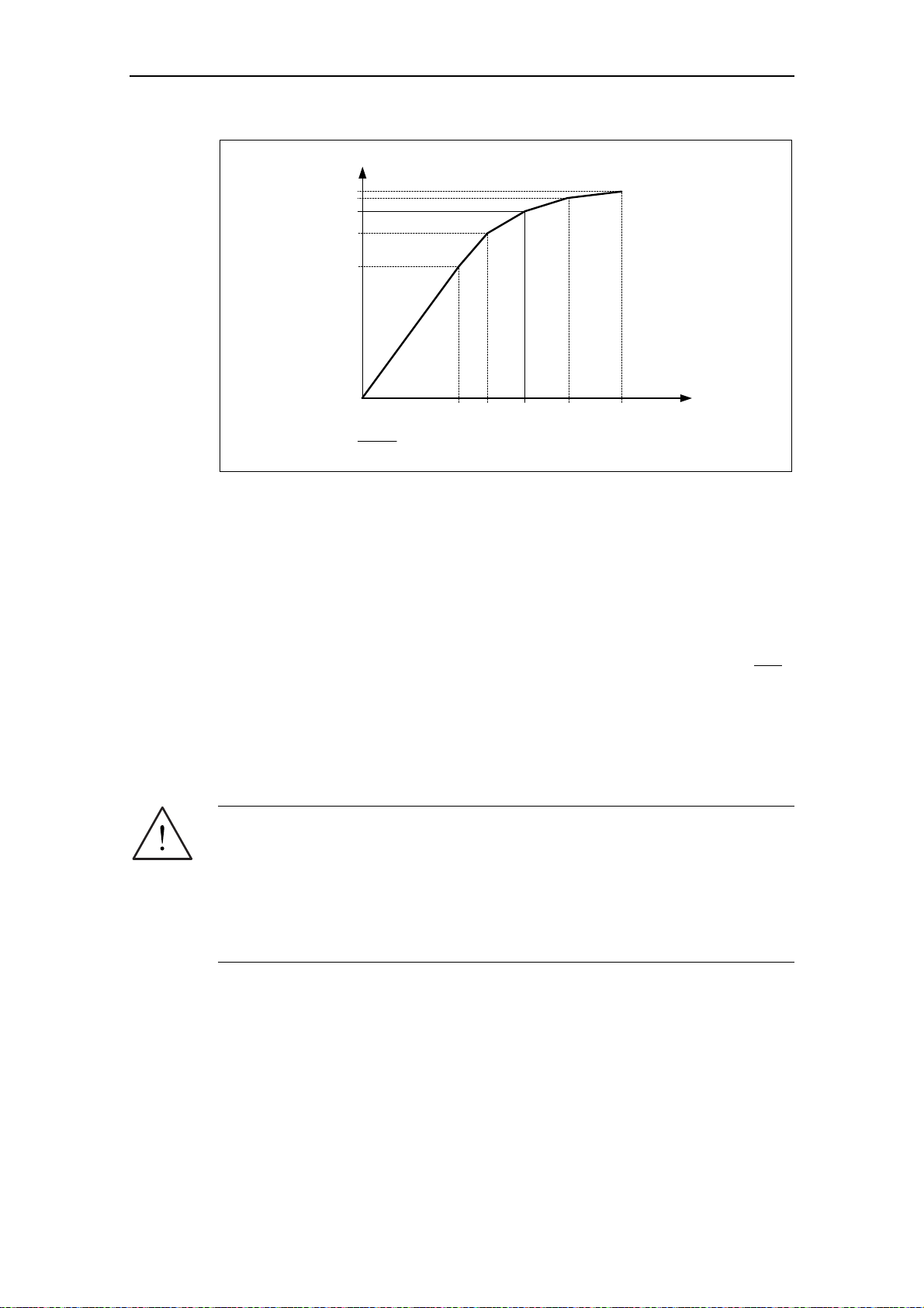
3 Functions Issue 10/06
Φ
[%]
P0365
P0364
100 %
P0363
P0362
0
[A]i
µ
[%]i
=
µ
Fig. 3-27 Magnetizing characteristic
P0366 P0367 100 % P0368 P0369
r0331
i
[%]
µ
After selecting the motor data identification using parameter P1910, alarm A0541 is
immediately generated. The motor identification routine is started by the ON
command and different excitation signals are impressed in the motor (DC and AC
voltages). This measurement is carried-out with the motor at a standstill and it
takes, including the data calculation per selection (P1910 = 1.3) between 20 s ... 4
min. The identification time depends on the motor and increases with its size (this
takes approx. 4 min for a 200 kW motor).
The motor data identification routine must be carried-out with the motor in the cold
condition so that the motor resistance values saved can be assigned to the
parameter of the ambient temperature P0625. Only then is correct temperature
adaptation of the resistances possible during operation.
The motor data identification routine operates with the results of the "Complete
parameterization" P0340 = 1 or the motor equivalent diagram data which was last
saved. The results become increasingly better the more times that the identification
routine is executed (up to 3 times).
WARNING
¾ It is not permissible to carry-out the motor identification routine for loads which
are potentially hazardous (e.g. suspended loads for crane applications). Before
starting the motor data identification routine, the potentially hazardous load
must be secured (e.g. by lowering the load to the floor or clamping the load
using the motor holding brake).
¾ When starting the motor data identification routine, the rotor can move into a
preferred position. This is more significant for larger motors.
MICROMASTER 440 Operating Instructions
92 6SE6400-5AW00-0BP0
Page 93

Issue 10/06 3 Functions
NOTE
¾ The equivalent circuit data (P0350, P0354, P0356, P0358, P0360), with the
exception of parameter P0350, should be entered as phase values. In this case,
parameter P0350 (line-to-line value) corresponds to twice the phase value.
¾ Equivalent circuit diagram data always refer to the star circuit configuration
equivalent circuit diagram data. If data for the delta equivalent circuit diagram is
available, then this data must be converted into the star equivalent circuit
diagram data before being entered (refer to Section 0).
¾ The motor cable resistance P0352 is defined as phase value
¾ During the motor identification routine, the stator resistance and the motor cable
resistance are determined and entered into parameter P0350. If a correction is
made in parameter P0352, then MICROMASTER defines the motor cable
resistance using the following relationship: P0352 = 0.2 * P0350.
¾ If the motor cable resistance is known, then the value can be entered into
parameter P0352 after
the motor data identification. The stator resistance is
appropriately reduced as a result of this entry and is therefore more precisely
adapted to the actual application.
¾ It is not necessary to lock the motor rotor for the motor data identification
routine. However, if it is possible to lock the motor rotor during the identification
routine (e.g. by closing the motor holding brake), then this should be used to
determine the equivalent circuit diagram data.
¾ The following formula can be applied to check the correctness of the motor
rating plate data:
= √3 ∗ V
P
N
with P
V
I
N Υ
N Υ
cos
η efficiency
∗ I
N Υ
, V
N ∆
, I
rated motor current (star / delta)
N ∆
∗ cosϕ ∗ η ≈ √3 ∗ V
NΥ
rated motor power
N
rated motor voltage (star / delta)
N ∆
∗ I
ϕ power factor
∗ cosϕ ∗ η
N∆
Motor data identification routine
yes no
START
P0625 = ?
| Motor temp. - P0625|
≤ 5 °C ?
Allow the motor
to cool down
Ambient motor temperature (entered in °C)
The motor ambient temperature is entered at the instant that motor data is
being determined (factory setting:
The difference between the motor temperature and the motor ambient
temperature P0625 must lie in the tolerance range of approx. ± 5 °C. If this is
not the case, then the motor data identification routine can only be carried-out
after the motor has cooled down.
Factory setting
20 °C
20 °C).
MICROMASTER 440 Operating Instructions
6SE6400-5AW00-0BP0
93
Page 94

3 Functions Issue 10/06
P1910 = 1
A0541
After the motor data identification routine has been completed, p1910 is reset
After the motor identification routine has been completed, p1910 is reset
ON
OFF1
P1910 = 3
A0541
ON
OFF1
END
Select motor data identification with P1910 = 1
p1910 = 1: Identifies the motor parameter with parameter change.
These are accepted and applied to the controller.
When p1910 = 1 is selected, Alarm A0541 (motor data identification active)
is output, and internally p0340 is set to 3.
Starts the motor data identification run with p1910 = 1
The measuring operation is initiated with the continuous (steady-state) ON
command. The motor aligns itself and current flows through it. Diagnostics is
possible using r0069 (CO: Phase current).
(p1910 = 0, motor data identification routine inhibited) and Alarm A0541 is
cleared (deleted).
In order to set the frequency converter into a defined state, an OFF1 command
must be issued before the next step.
Select motor data identification with P1910 = 3
p1910 = 3: Identifies the saturation characteristic with parameter change.
When p1910 = 3 is selected, Alarm A0541 (motor data identification active)
is output and internally, p0340 is set to 2.
Starts the motor data identification run with P1910 = 3
The measuring operation must be started with a continuous ON command.
(p1910 = 0, motor data identification routine inhibited) and Alarm A0541 is
cleared (deleted).
In order to set the frequency converter into a defined state, an OFF1 command
must be issued before the next step.
0
0
If problems occur during the identification run, e.g. the current controller oscillates,
then the rating plate data should be re-checked and an approximately correct
magnetizing current P0320 entered. The motor data identification routine should
then be re-started by calling P0340 = 1 (refer to Section 3.5.4).
MICROMASTER 440 Operating Instructions
94 6SE6400-5AW00-0BP0
Page 95

Issue 10/06 3 Functions
3.5.6 Magnetizing current
¾ The value of the magnetizing current r0331/P0320 has a significant influence
on the closed-loop control. This cannot be measured at standstill. This
means that the value is estimated for standard
standard
using the automatic parameterization P0340=1 (P0320=0; result in
r0331).
¾ If the deviation of the magnetizing current is too high, then the values for the
magnetizing reactance and those of the rotor resistance will not be able to
be accurately determined.
¾ Especially for third-party motors it is important that the magnetizing current
that is determined, is carefully checked and if required, appropriately
corrected.
The procedure to manually determine the magnetizing current and to re-calculate
the equivalent circuit diagram data when the drive is operated with closed-loop
vector control (P1300 = 20/21) is shown in the following.
4-pole 1LA7 SIEMENS
MICROMASTER 440 Operating Instructions
6SE6400-5AW00-0BP0
95
Page 96

3 Functions Issue 10/06
f
START
Quick
commissioning
Quick commissioning routine
Using the quick commissioning routine the frequency inverter is adapted to the
motor and important technology parameters are set.
Motor data
identificationdenti
Motor data identification routine
Using the motor data identification routine motor equivalent circuit diagram
data is determined using a measuring technique.
Operation under
no-load conditions
Determing the magnetizing current
In order to determine the magnetizing current (P0320/r0331), the motor should
be accelerated
operating conditions.
up to approximately 80% of its rated speed under no-load
In so doing, the following conditions must be carefully maintained:
− the vector control must be activated, P1300 = 20.21
− no field weakening (r0056.8 = 0)
− flux setpoint, r1598 = 100 %
− no efficiency optimization, P1580 = 0 %
No-load operation means that the motor is operated without a load (i.e.
no coupled driven machine).
Under steady-state conditions, a current r0027 is obtained that approximately
corresponds to the rated magnetizing current r0331. (the current is always
less than the no-load current for a pure V/f control).
Criterium
fulfilled ?
no yes
Measuring and entering the magnetizing current and therefore the associated
new calculation of the equivalent circuit diagram data of the motor is an
iterative procedure. It must be repeated at least 2-3 times until the following
criteria are fulfilled:
−
The more accurate the value of the magnetizing current that was
entered, the better the
actual value (r0084=96..104%) of the observer model.
− The output Xm adaptation (r1787) of the observer model should be
as low as possible. Good values lie between
flux setpoint (r1598=100%) matches the flux
1-5%. The less that the
Xh adaptation of the observer must operate, the sensitivity of the motor
parameters after power failures are that much less sensitive.
NOTE
In order to display r0084 at the BOP/AOP, the LEVEL 4 parameters must be
enabled using service parameter P3950=46.
P0320 = ...
Calculating P0320
0
Now, the new value can be entered in P0320 from the determined flux-
P0340 = 1
generating current component
P0320 = r0029 * 100 / P0305
Calculating the motor parameters
r0029 by applying the following equation.
0
The values of the motor equivalent circuit diagram data are calculated from the
entered rating plate data. In addition, the parameters of the controls are pre-set
(subsequently optimized) (P0340 = 3).
END
MICROMASTER 440 Operating Instructions
96 6SE6400-5AW00-0BP0
Page 97

Issue 10/06 3 Functions
3.5.7 Commissioning the application
After the motor – drive inverter combination was commissioned using the quick or
series commissioning, in the following step parameters should be adapted and set
according to the technological requirements. As an example, the following points
should be considered:
¾ Functional requirements of the drive inverter (e.g. closed-loop process control
with PID controller)
¾ Limit values
¾ Dynamic requirements
¾ Starting torques
¾ Load surge requirement
¾ Overload
¾ Diagnostics
If the application includes a function, which is not covered by the quick or series
commissioning, then the following sections of the function description or the
parameter list should be considered.
Adapting the drive inverter to the application
The parameters designated with * offer more setting possibilities than are listed
here. Refer to the parameter list for additional setting possibilities.
START
P0003 = 3
Factory setting
User access level *
1 Standard: Allows access into most frequently used parameters
2 Extended: Allows extended access e.g. to inverter I/O functions
3 Expert (For expert use only)
3.5.7.1 Serial Interface (USS)
P2010 =...
P2011 =...
P2012 =...
P2013 =...
USS baud rate
Sets baud rate for USS communication.
USS address
Sets unique address for inverter.
USS PZD length
Defines the number of 16-bit words in PZD part of USS telegram.
USS PKW length
Defines the number of 16-bit words in PKW part of USS telegram.
6
Possible
Settings:
4 2400 Baud
5 4800 Baud
0
6 9600 Baud
7 19200 Baud
2
8 38400 Baud
9 57600 Baud
10 76800 Baud
127
11 93750 Baud
12 115200 Baud
1
MICROMASTER 440 Operating Instructions
6SE6400-5AW00-0BP0
97
Page 98
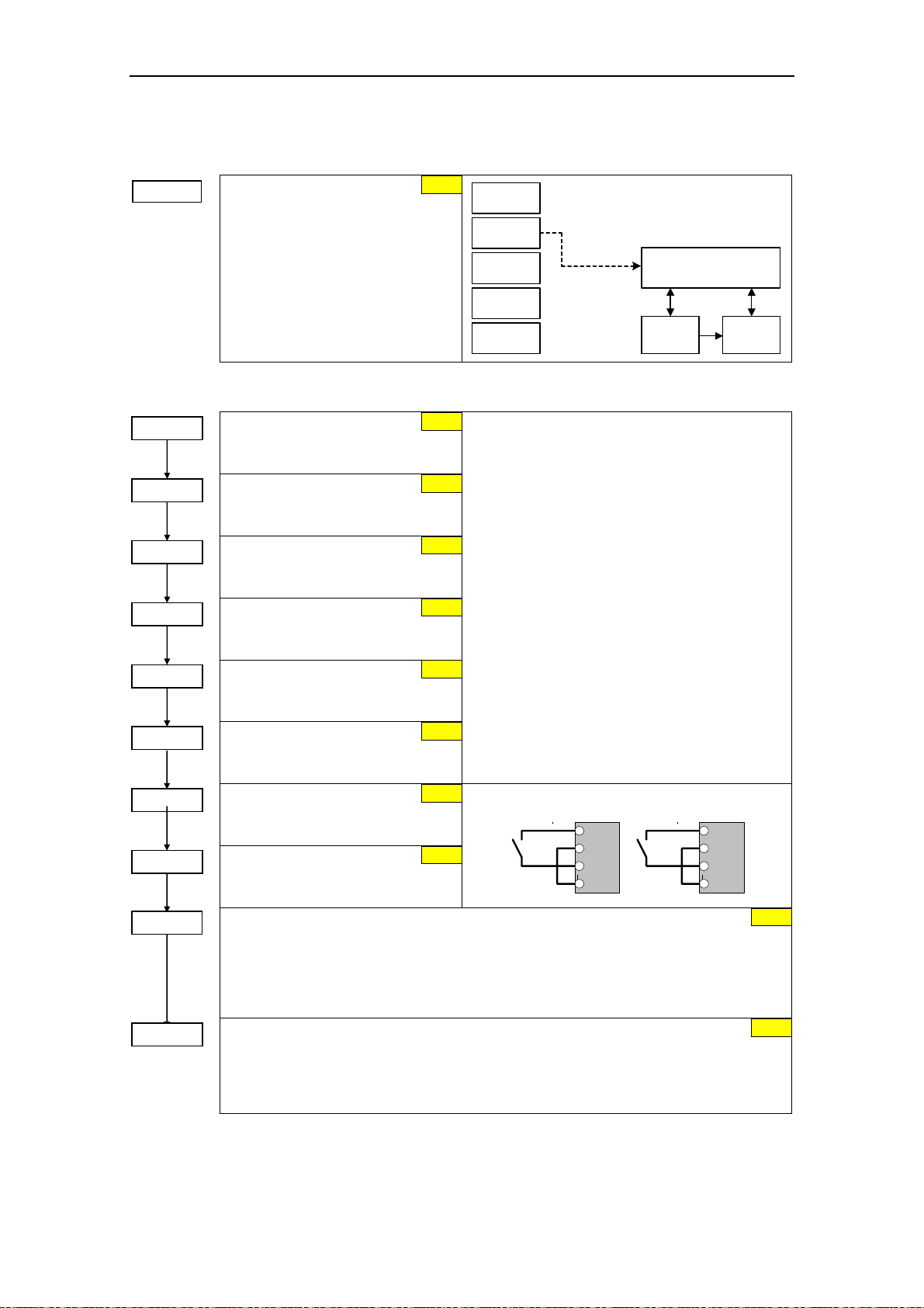
3 Functions Issue 10/06
3.5.7.2 Selection of command source
P0700 =...
Selection of
command source
Selects digital command source.
0 Factory fault setting
1 BOP (keypad)
2 Terminal
4 USS on BOP link
5 USS on COM link
6 CB on COM link
3.5.7.3 Digital input (DIN)
P0701 = ...
P0702 = ...
P0703 = ...
P0704 = ...
P0705 = ...
P0706 = ...
P0707 = 0
P0708 = 0
P0724 = ...
P0725 = ...
Function digital input 1
Terminal 5
1 ON / OFF1
Function digital input 2
Terminal 6
12 Reverse
Function digital input 3
Terminal 7
9 Fault acknowledge
Function digital input 4
Terminal 8
15 Fixed setpoint (Direct selection)
Function digital input 5
Terminal 16
15 Fixed setpoint (Direct selection)
Function digital input 6
Terminal 17
15 Fixed setpoint (Direct selection)
Function digital input 7
Via analog input, Terminal 3
0 Digital input disabled
Function digital input 8
Via analog input, Terminal 10
0 Digital input disabled
Debounce time for digital inputs
Defines debounce time (filtering time) used for digital inputs.
0 No debounce time
1 2.5 ms debounce time
2 8.2 ms debounce time
3 12.3 ms debounce time
PNP / NPN digital inputs
Change-over (toggles) between high active (PNP) and low active (NPN). This applies to all
digital inputs simultaneously.
0 NPN mode ==> low active
1 PNP mode ==> high active
2
1
BOP
Terminals
USS
BOP link
USS
COM link
CB
COM link
P0700 = 2
Possible Settings:
Sequence control
Setpoint
channel
Motor
control
0 Digital input disabled
1 ON / OFF1
2 ON + Reverse / OFF1
12
3 OFF2 – coast to standstill
4 OFF3 – quick ramp-down
9 Fault acknowledge
10 JOG right
9
11 JOG left
12 Reverse
13 MOP up (increase frequency)
14 MOP down (decrease frequency)
15
15 Fixed setpoint (Direct selection)
16 Fixed setpoint (Direct selection + ON)
17 Fixed setpoint (Binary coded selection + ON)
21 Local/remote
15
25 DC brake enable
29 External trip
33 Disable additional freq setpoint
99 Enable BICO parameterization
15
0
0
ON > 3,9 V, OFF < 1,7 V
DIN7
1
2
3
4
DIN8
1
2
10
11
3
1
MICROMASTER 440 Operating Instructions
98 6SE6400-5AW00-0BP0
Page 99

Issue 10/06 3 Functions
DIN channel (e.g. DIN1 - PNP (P0725 = 1))
Kl.9
P24 (PNP)
Kl.28
0 V (NPN)
PNP/NPN DIN
24 V
0
1
0 V
0 ... 1
P0725 (1)
0
1
3.5.7.4 Digital output (DOUT)
P0731 = ...
P0732 = ...
P0733 = ...
P0748 = ...
BI: Function of digital output 1 *
Defines source of digital output 1.
BI: Function of digital output 2 *
Defines source of digital output 2.
BI: Function of digital output 3 *
Defines source of digital output 3.
Invert digital output
Defines high and low states of relay for a
given function.
DOUT channel
BI: Fct. of DOUT 1
Function
xxxx.y
rxxxx.y
P0731.C
P0731 = xxxx.y
24 V
(52:3)
Debounce time: DIN
0 ... 3
P0724 (3)
T0
r0722
.0
r0722
CO/BO: Bin.inp.val
52.3
Common Settings:
&
52.0 Drive ready 0
52.1 Drive ready to run 0
52.7
52.2 Drive running 0
52.3 Drive fault active 0
52.4 OFF2 active 1
0.0
52.5 OFF3 active 1
52.6 Switch on inhibit active 0
52.7 Drive warning active 0
0
52.8 Deviation, setpoint / actual value 1
52.9 Control from PLC (PZD control) 0
52.A Maximum frequency reached 0
52.B Alarm: Motor current limiting 1
52.C Motor holding brake (MHB) active 0
52.D Motor overload 1
52.E Motor direction of rotation, clockwise 0
52.F Frequency inverter overload 1
53.0 DC brake active 0
.
Invert DOUTs
0 ... 7
P0748 (0)
CO/BO: State DOUTs
r0747
0
-1
1
Relay :
r0747
Text
DC 30 V / 5 A
AC 250 V / 2 A
max. opening / closing time
5 / 10 ms
.0
int. 24 V
max. 100 mA
COM
NO
NC
P0701
Function
Pxxxx BI: ...
Kl.9
Kl.20
Kl.19
or
Kl.18
Kl.28
MICROMASTER 440 Operating Instructions
6SE6400-5AW00-0BP0
99
Page 100

3 Functions Issue 10/06
3.5.7.5 Selection of frequency setpoint
P1000 =...
Selection of frequency setpoint
0 No main setpoint
1 MOP setpoint
2 Analog setpoint
3 Fixed frequency
4 USS on BOP link
5 USS on COM link
6 CB on COM link
7 Analog setpoint 2
10 No main setpoint + MOP setpoint
11 MOP setpoint + MOP setpoint
12 Analog setpoint + MOP setpoint
...
76 CB on COM link + Analog setpoint 2
77 Analog setpoint 2 + Analog setpoint 2
NOTE
In addition to the main setpoint, a supplementary setpoint can be entered using P1000
Example P1000 = 12 :
P1000 = 12 ? P1070 = 755
P1000 = 12 ? P1075 = 1050
MOP
ADC
P1070 CI: Main setpoint
r0755 CO: Act. ADC after scal. [4000h]
P1075 CI: Additional setpoint
r1050 CO: Act. Output freq. of the MOP
Sequence control
2
P1074 = ...
P1075 = ...
P1076 = ...
FF
USS
BOP link
USS
COM link
CB
COM link
ADC2
P1000 = 12
P1000 = 1
2
Additonal
setpoint
Main
setpoint
Setpoint
channel
Motor
control
BI: Disable additional setpoint
Deaktiviert den Zusatzsollwert (ZUSW).
CI: Additional setpoint
Defines the source of the additional setpoint which is added to the main setpoint.
Common settings:
755 Analog input setpoint
1024 Fixed frequency setpoint
1050 MOP setpoint
CI: Additional setpoint scaling
Defines the source to scale the additional setpoint.
Common settings:
1 Scaling of 1.0 (100 %)
755 Analog input setpoint
1024 Fixed frequency setpoint
1050 MOP setpoint
0:0
0:0
1:0
MICROMASTER 440 Operating Instructions
100 6SE6400-5AW00-0BP0
 Loading...