

Page 1

Watson-Marlow Alitea 114 pumpheads: operating instructions 1
WATSON-MARLOW MANUALS
Watson-Marlow Alitea
114 pumpheads
m-114pumphead-gb-04
Contents
1 Declaration of incorporation 2
2 Safety notes 3
3 Product specifications 4
3.1 Dimensions 4
4 Good pump installation
practice 5
4.1 General recommendations 5
4.2 Do’s and do not’s 6
4.3 Troubleshooting 6
5 Pumphead mounting 7
6 Torque requirement 8
7 Tube holder positioning 9
7.1 Tube holder repositioning 10
8 Tube loading 11
9 Flow rates and
pressure capabilities 12
10 Tubing part numbers 14
11 Trademarks 15
12 Patient-connected use: warning 15
13 Publication history 15
Page 2

Watson-Marlow Alitea 114 pumpheads: operating instructions 2
1 Declaration of incorporation
When this unit is to be installed into a machine or is to be assembled with
other machines for installations, it must not be put into service until the
relevant machinery has been declared in conformity with the Machinery
Directive 2006/42/EC.
Responsible person: Lars Eriksson, General Manager, Watson-Marlow Alitea AB,
Hammarby Fabriksvag 29-31, 120 33 Stockholm, Sweden.
Telephone +46 8 556 556 00. Fax +46 8 556 556 25.
The information in this user guide is believed to be correct at the time of publication. However, Watson-Marlow Alitea accepts no liability for errors or omissions.
Watson-Marlow Alitea has a policy of continuous product improvement, and reserves
the right to alter specifications without notice. This manual is intended for use only
with the pump it was issued with. Earlier or later models may differ. The most upto-date manuals appear on the Watson-Marlow Pumps Group website:
http://www.watson-marlow.com
114DV, 114DVP
September 2014
Page 3

Watson-Marlow Alitea 114 pumpheads: operating instructions 3
2 Safety notes
In the interests of safety, this pumphead and the tubing selected should only be
used by competent, suitably trained personnel after they have read and understood
this manual, and considered any hazard involved. If the product is used in a manner not specified by Watson-Marlow Ltd, the protection provided by the product may
be impaired.
Any person who is involved in the installation or maintenance of this equipment
should be fully competent to carry out the work. In the UK this person should also
be familiar with the Health and Safety at Work Act 1974.
There are moving parts inside the pumphead. Before opening the flip top,
ensure that the following safety directions are followed.
Ensure that the pump is isolated from the mains power.
Ensure that there is no pressure in the pipeline.
If a tube failure has occurred, ensure that any fluid in the pumphead has been
allowed to drain to a suitable vessel, container or drain.
Protective clothing and eye protection must be worn if hazardous fluids are
pumped.
Primary operator protection from rotating parts of the pump is provided by the
pumphead track.
This pump must be used only for its intended purpose.
This symbol, used on the pump or in this manual,
means: Caution, refer to accompanying documents.
This symbol, used on the pump or in this manual,
means: Do not allow fingers to contact moving parts.
114DV, 114DVP
Page 4
Watson-Marlow Alitea 114 pumpheads: operating instructions 4
3 Product specifications
114 pumpheads
This compact pumphead allows automatic tube positioning and tension in seconds,
with no need for operator adjustment to achieve high accuracy and repeated precision dosing.
For continous tubing, 1.6mm wall
Recommended for continous duty
Four-roller pumphead
Max speed: 400 rpm continous and 600 rpm intermittent
Up to 340 ml/min continuous flow and up to 510 ml/min intermittent flow
Two tube-holder positions to accept tube in bore sizes from 0.5mm to 4.8mm
Models with occlusion settings for standard or high-pressure operation
Universal drive connection for shafts from 6mm diameter to 10mm diameter
Operating temp: -10° to 45°C
This manual describes the visible rotation pumpheads, 114DV and 114DVP. For
versions without visible rotation: 114D—refer to 114DV; 114DP—refer to 114DVP.
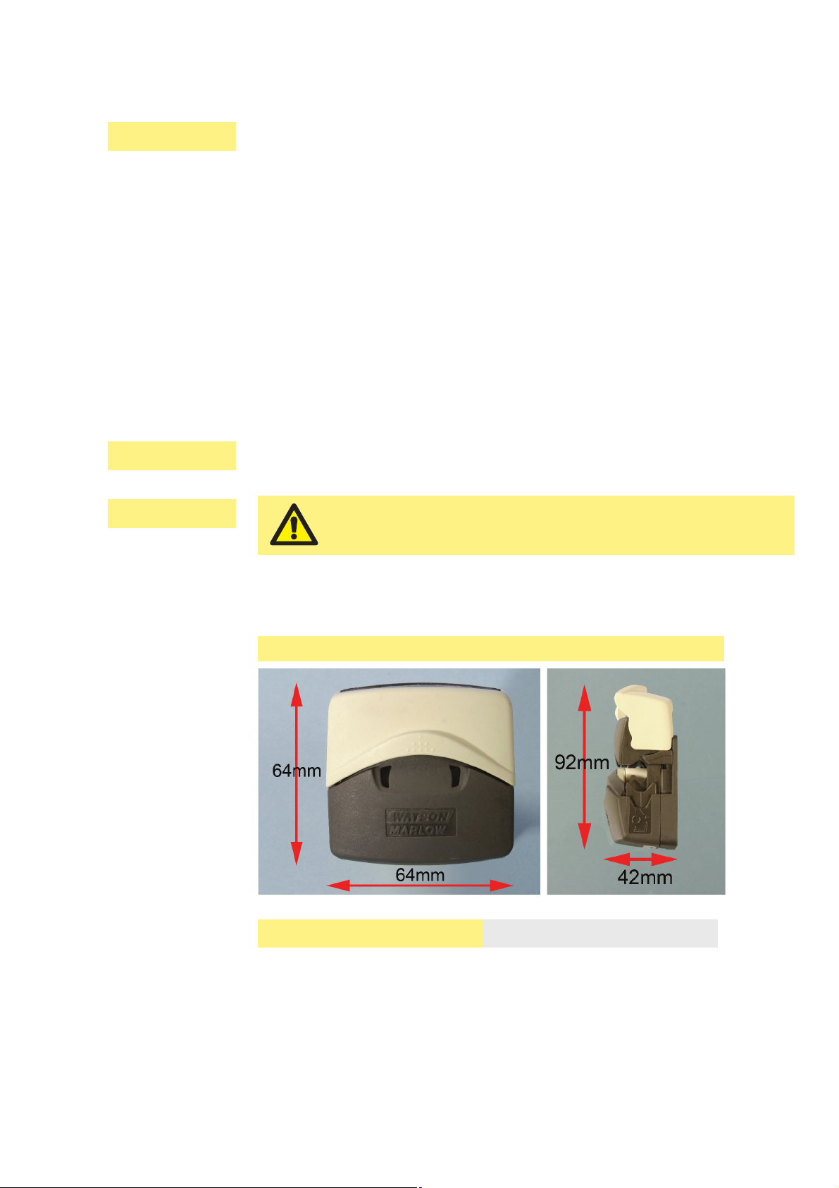
3.1 Dimensions
114 pumphead
Unit weight 0.1kg
This product does not comply with the ATEX directive
and must not be used in explosive atmospheres.
114DV, 114DVP
114D, 114DP
114DV, 114DVP
Page 5

Watson-Marlow Alitea 114 pumpheads: operating instructions 5
4 Good pump installation practice
4.1 General recommendations
A correctly engineered installation will promote long tube life.
The pump may be set up so that the direction of rotor rotation is clockwise or counter-clockwise, whichever is convenient. Please note, however, that tube life will be
greater if the rotor rotates clockwise; and that performance against pressure will be
maximised if the rotor rotates counter-clockwise.
Peristaltic pumps are self-priming and self-sealing against backflow. No valves are
required in inlet or discharge lines, except as described below. Valves in the process
flow must be opened before the pump operates. Users are advised to fit a pressure
relief device between the pump and any valve on the discharge side of the pump to
protect against damage caused by accidental operation with the discharge valve
closed.
114DV, 114DVP
Page 6

Watson-Marlow Alitea 114 pumpheads: operating instructions 6
4.2 Do’s and do not’s
Do not build a pump into a tight location without adequate airflow around the pump.
Do keep delivery and suction tubes as short and direct as possible - though ideally
not shorter than 0.5m - and follow the straightest route. Use bends of large radius:
at least four times the tubing diameter. Ensure that connecting pipework and fittings
are suitably rated to handle the predicted pipeline pressure. Try to avoid pipe reducers and lengths of smaller bore tubing than the pumphead section, particularly in
pipelines on the suction side. Any valves in the pipeline (not usually needed with
a self-priming peristaltic pump) must not restrict the flow. Any valves in the flow line
must be open when the pump is running.
Do use suction and delivery pipes equal to or larger than the bore of the tube in the
pumphead. When pumping viscous fluids use pipe runs with a bore several times
larger than the pump tube.
Do ensure that on longer tube runs at least 0.5m of smooth bore flexible tubing is
connected to the inlet and discharge port of the pumphead to help to minimise
impulse losses and pulsation in the pipeline. This is especially important with viscous
fluids and when connecting to rigid pipework.
Do site the pump at or just below the level of the fluid to be pumped if possible.
This will ensure flooded suction and maximum pumping efficiency.
Do keep the pumphead track and all moving parts clean and free from contamination and debris.
Do run at slow speed when pumping viscous fluids. Flooded suction will enhance
pumping performance in all cases, particularly for materials of a viscous nature.
Do recalibrate after changing pump tubes, fluid, or any connecting pipework. It is
also recommended that the pump is recalibrated periodically to maintain accuracy.
Tube selection: The chemical compatibility lists published in Watson-Marlow publications are guides. If in doubt about the compatibility of a tube material and the
duty fluid, request a Watson-Marlow tube sample card for immersion trials.
4.3 Troubleshooting
If the pump runs but there is little or no flow, make the following checks:
Check that the tube is in the pumphead.
Check that fluid is supplied to the pump.
Check that the tube is not split or burst.
Check for any kinks or blockages in the lines.
Check that any valves in the lines are open.
Check that the correct wall-thickness tube is being used.
Check direction of rotation.
114DV, 114DVP
114DV, 114DVP
Page 7

Watson-Marlow Alitea 114 pumpheads: operating instructions 7
5 Pumphead mounting
Lift the flip top until fully open.
Mount the pumphead on its supporting plate through the holes indicated below,
using two Allen-key headed M4 screws, length equal to 5mm + the thickness of
the mount. Tighten them to a maximum of 0.5Nm.
Drive shafts 8mm in diameter are recommended, but shafts from 6mm diameter to
10mm diameter are acceptable.
114DV, 114DVP
Page 8

Watson-Marlow Alitea 114 pumpheads: operating instructions 8
0.3
0.25
0.2
0.15
0.1
0.05
0
Nm
Tube bore
0.5
Torque requirement, 1.6mm wall tube
0.8
1.6
2.4
3.2 4.0 4.8
Required torque depends on many parameters. The chart above includes standard
materials, direction, occlusion setting, pressure and running temperature.
Starting torques are approximately the above figures x 2.
Assess your application’s torque requirement from the top of the arrows if all the
parameters listed are those requiring more torque, as shown in the graph below, or
to be sure to have sufficient torque for all conditions; use the bottom of the arrows
if all the parameters listed are those requiring less torque, as shown in the graph
below.
Factors affecting torque requirement
Pumpsil
CW
Standard occlusion
High temperature
CCW
Bioprene
+Pressure occlusion
Low temperature
More torque
Less torque
6 Torque requirement
114DV, 114DVP
Page 9

Watson-Marlow Alitea 114 pumpheads: operating instructions 9
7 Tube holder positioning
The pumphead can be adjusted to accommodate 1.6mm wall tubing in sizes from
0.5mm bore to 4.8mm bore.
Inner position, for small tubing Outer position, for large tubing
With the smaller bore tubes of 0.5mm, 0.8mm and 1.6mm the inner position must
be used to prevent the risk of tube slipping through the clamps and wandering
across the rollers causing premature tube rupture.
With the larger bore tubes of 4.0mm and 4.8mm the outer position must be used to
prevent the flow rate being excessively reduced.
For tubing bores of 2.4mm and 3.2mm either setting may be used, as appropriate
for the application. The inner setting will clamp the tube harder, reducing tube slip
but has the potential to marginally reduce flow rate. The outer setting will optimise
flow rate but the risk of tube slip is increased.
114DV, 114DVP
Tube holder position
Tube bore size 0.5mm 0.8mm 1.6mm 2.4mm 3.2mm 4.0mm 4.8mm
Inner
Outer
Page 10

Watson-Marlow Alitea 114 pumpheads: operating instructions 10
To change from the large tube to the small tube setting
Switch off the pump before changing the tube holder position. Use a pointed
device such as a ball-point pen to reposition the lower tube holders on both sides
of the pumphead.
Press down and slightly away from the front of the pumphead, as shown in the
first picture above.
Maintain the angled downward pressure and push away from the front of the
pumphead. The jaw clicks into a new position.
Release the pressure. The jaw rises into its correct alignment. If it does not
rise, repeat the procedure, being sure to maintain downward pressure until
release.
Adjust the tube holder on the other side of the pumphead in the same way.
To change from the small tube to the large tube setting
Carry out the procedure described above, but pushing towards the front of the
pumphead.
Lift the flip top until fully open.
Place the pointed device pointing
down into the small depression pictured here.
Note: The pictures on the previous page show the tube holders’ correct positions for
small and large tubing. If a tube holder is not vertical relative to the body of the
pumphead, it is wrongly positioned. Follow the instructions above to reposition it.
7.1 Tube holder repositioning
114DV, 114DVP
Page 11

Watson-Marlow Alitea 114 pumpheads: operating instructions 11
8 Tube loading
Lift the flip top until fully open.
Select enough tube length for the curve of the pump track. Place the tube
between the rotor rollers and the track, pressed against the pumphead inner
wall. The tube must not be twisted or stretched against the rollers.
Lower the flip top until it clicks into its fully closed position. The track closes
automatically and the tube is stretched correctly as it does so.
Click!
Switch off the pump before tube loading.
Check that the tube holders on both sides of the pumphead are correctly set for the
size of tube you are using.
114DV, 114DVP
Page 12

Watson-Marlow Alitea 114 pumpheads: operating instructions 12
9 Flow rates and pressure
capabilities
Pumping conditions
For precise and repeatable performance it is important to determine flow rates under
operating conditions for each new piece of tubing.
114 pumpheads’ flow rates are the same whether rotating clockwise (cw) or counter-clockwise (ccw). Their pressure capabilities vary depending on rotation sense.
114, cw and ccw rotation:
Flow rates, ml/min
Tube bore
size
0.5mm 0.8mm 1.6mm 2.4mm 3.2mm 4.0mm 4.8mm
ml/rev 0.02 0.04 0.14 0.29 0.47 0.67 0.85
30 rpm 0.7 1.3 4.2 8.7 14 20 25.5
60 rpm 1.4 2.6 8.4 17.5 28.5 40.5 51
100 rpm 2.2 4.3 14 29 47.5 67 85
190 rpm 4.3 8.2 26.5 55 90.5 128 160
200 rpm 4.6 8.6 28 58 95 135 170
350 rpm 8.0 15 49 100 165 235 300
400 rpm 9.1 17 56 115 190 270 340
600 rpm 13.5 26 84 175 285 405 510
Flow rate tests were carried out using water at zero suction pressure and Bioprene
tubing, with the pumphead rotating cw. Actual flow rates achieved may vary because
of changes in temperature, viscosity, inlet and discharge pressures, system configuration and tubing performance against time. Flow rates may also vary due to normal manufacturing tolerances of the tubing.
Reduce the flow rates quoted by 10% if using Pumpsil tubing.
Recommended tubing
114DV: Bioprene, Marprene, Pumpsil, STA-PURE PCS and STA-PURE PFL
(formerly CHEM-SURE).
114DVP: Bioprene, Marprene, Pumpsil, STA-PURE PCS, STA-PURE PFL
(formerly CHEM-SURE), PVC and Neoprene.
114DV, 114DVP
114DV
114DVP
Page 13

Watson-Marlow Alitea 114 pumpheads: operating instructions 13
Marprene tubing, 1.6mm wall, 100 rpm, CCW rotation
Pressure tests were carried out using water at constant delivery pressure. Actual
pressures achieved may vary because of actual tube dimensions, changes in temperature, viscosity, system configuration and tubing performance against time.
Direction of rotation
CCW: The pressure / flow curves above show performance in counter clockwise
rotation. This direction is recommended for pressure applications.
CW: Clockwise rotation optimizes the pump performance regarding tube life and
required torque. Clockwise rotation is recommended for low or no pressure applications. Suction performance and flow are the same as for CCW rotation.
Pressure and flow performance curves
Marprene tubing, 1.6mm wall, 100 rpm, CCW rotation
114DV
114DVP
114DV, 114DVP
suction (bar) pressure (bar)
0123 54
Flow rate: ml/min
0
20
40
70
80
100
10
30
50
60
90
-0.5 -0.3 0-0.1-0.2-0.4
0.8 x 1.6
1.6 x 1.6
4.8 x 1.6
4.0 x 1.6
3.2 x 1.6
2.4 x 1.6
114DV, standard occlusion
suction (bar) pressure (bar)
0123 54
Flow rate: ml/min
0
20
40
70
80
100
10
30
50
60
90
-0.5 -0.3 0-0.1-0.2-0.4
0.8 x 1.6
1.6 x 1.6
4.8 x 1.6
4.0 x 1.6
3.2 x 1.6
2.4 x 1.6
114DVP, +Pressure occlusion
Page 14

Watson-Marlow Alitea 114 pumpheads: operating instructions 14
10 Tubing part numbers
1.6mm wall tubing for 114 pumpheads
mm # Marprene Bioprene Pumpsil
0.5 112 902.0005.016 933.0005.016 913.A005.016
0.8 13 902.0008.016 933.0008.016 913.A008.016
1.6 14 902.0016.016 933.0016.016 913.A016.016
2.4 902.0024.016 933.0024.016 913.A024.016
3.2 16 902.0032.016 933.0032.016 913.A032.016
4.0 933.0040.016
4.8 25 902.0048.016 933.0048.016 913.A048.016
mm # Tygon E3603* Neoprene*
0.8 13 920.0008.016
1.6 14 E3603.016.16 920.0016.016
3.2 16 E3603.032.16 920.0032.016
4.0 E3603.040.16
4.8 25 E3603.048.16 920.0048.016
mm # STA-PURE PCS STA-PURE PFL
1.6 14 960.0016.016 965.0016.016
3.2 16 960.0032.016 965.0032.016
4.8 25 960.0048.016 965.0048.016
114DV, 114DVP
* Recommended for 114DVP +Pressure pumpheads only
Page 15

Watson-Marlow Alitea 114 pumpheads: operating instructions 15
11 Trademarks
Bioprene, LoadSure, Marprene, Pumpsil and Watson-Marlow are trademarks
of Watson-Marlow Limited.
Tygon is a trademark of Saint Gobain Corporation
STA-PURE PFL and STA-PURE PCS are trademarks of W.L.Gore and Associates.
12 Warning not to use pumps in
patient-connected applications
Warning These products are not designed for use in, and should not be used for
patient-connected applications.
13 Publication history
m-114pumphead-gb-03.qxp: Watson-Marlow 114 pumphead.
Revised 09 14.
114DV, 114DVP
114DV, 114DVP
114DV, 114DVP
 Loading...