

Page 1
INSTALLATION INSTRUCTIONS
UNIVERSAL PLOW MOUNT KIT
Part Number: 91810
GENERAL SAFETY PRECAUTIONS
Your safety, and the safety of others, is very important. To help you make informed decisions about safety, we have
provided installation and operating instructions and other information on labels and in this guide. This information
alerts you to potential hazards that could hurt you or others. It is not possible to warn you about all potential hazards
associated with this product, you must use your own good judgment.
CARELESS INSTALLATION AND OPERATION CAN RESULT IN SERIOUS INJURY OR EQUIPMENT DAMAGE. READ AND
UNDERSTAND ALL SAFETY PRECAUTIONS AND OPERATING INSTRUCTIONS BEFORE INSTALLING AND OPERATING THIS
PRODUCT.
This guide identies potential hazards and has important safety messages that help you and others avoid personal injury
or death. WARNING and CAUTION are signal words that identify the level of hazard. These signal words mean:
WARNING signals a hazard that could cause serious injury or death, if you do not follow recommendations. CAUTION
signals a hazard that may cause minor to moderate injury, if you do not follow recommendations.
This guide uses NOTICE to call attention to important mechanical information, and Note: to emphasize general
information worthy of special attention.
WARNING
IMPACT AND MOVING PARTS ENTANGLEMENT HAZARD
Failure to observe these instructions could lead to severe injury or death
• Always Read the Plow Operator’s Manual, the Winch Operator’s Manual and all warning labels before operating.
• Always use extreme caution when drilling on any vehicle. Make sure that all fuel lines, brake lines, electrical wires, and other objects are not punctured
or damaged when/if drilling on the vehicle. Thoroughly inspect the area to be drilled (on both sides of material) prior to drilling, and relocate any objects
that may be damaged. Failure to inspect the area to be drilled may result in vehicle damage, electrical shock, re or personal injury.
• Always wear safety glasses when installing this kit. A drilling operation will cause ying metal chips. Flying chips can cause eye injury.
• Always use extreme caution when cutting and trimming during tting.
• Always remove jewelry and wear eye protection.
• Always use appropriate and adequate care in lifting components into place.
• Always insure components will remain secure during installation and operation.
• Always tighten all nuts and bolts securely, per the installation instructions.
• Always operate the vehicle at a walking speed with the blade installed. Never exceed 5 mph (8 km/h), even with blade up.
• Always plow cautiously, impact with hidden or stationary object may cause the vehicle to stop suddenly or go out of control.
• Never operate the vehicle on slopes greater than 10 degrees with the plow installed.
• Never stand or ride on the plow.
• Always stay clear of moving parts and joints. Always keep others away when operating or adjusting plow.
• Always perform regular inspections and maintenance on the plow mechanism, fasteners, cable and related hardware.
• Always replace all worn or damaged parts before operating.
• Never operate this WARN product with damaged or missing parts.
• Always drive slowly over bumpy and rough terrain. Driving at speeds that cause the plow to bounce while in the up position can cause the winch to backdrive, causing the plow to work its way down. This may result in the plow impacting a stationary object and cause damage to the vehicle and operator
injury or death.
• Always drive at speeds such that the plow does not bounce and be aware of the plow position while driving at all times.
• Never raise the top of the plow above the headlights of the ATV, as it may damage the vehicle and plow.
Read installation and operating instructions thoroughly.
WARN INDUSTRIES, INC. 12900 S.E. Capps Road,
Clackamas, OR USA 97015-8903, 1-503-722-1200, FAX: 1-503-722-3000
Customer Service: 1-800-543-9276
Dealer Locator Service: 1-800-910-1122
International Sales/Customer Service: 1-503-722-3008
International Fax: 1-503-722-3005
©2013 Warn Industries, Inc. WARN® and the WARN logo are trademarks of Warn Industries Inc. 1 91853A0
Page 2
CAUTION
MOVING PARTS ENTANGLEMENT HAZARD
Failure to observe these instructions could lead to minor or moderate injury
• Always take time to fully read and understand the installation and Operations Guide included with this product.
• Never operate this product if you are under 16 years of age.
• Never operate this product when under the inuence of drugs, alcohol or medications.
Read installation and operating instructions thoroughly.
NOTICE
EQUIPMENT DAMAGE
• Use caution while mount is on vehicle without plow.
• Remove plow mount before recreational riding. Damage to plow mount parts may occur.
• Always store this product out of the weather between use to protect against corrosion and freezing, and keep product operating smoothly.
Read installation and operating instructions thoroughly.
TABLE OF CONTENTS
Tools Required .............................................................................................................................page 2
Parts List.........................................................................................................................................page 3
Installation ................................................................................................................................ page 4-7
Torque Specications ................................................................................................................page 6
Pre-Operation System Check .................................................................................................page 7
Maintenance/Care ......................................................................................................................page 8
Service ............................................................................................................................................ page 8
NOTES
• Your WARN® Universal Plow Mount Kit ts most, but not all ATVs. For any installation questions, contact your WARN
product dealer where you purchased your Universal Plow Mount Kit. If you are still unable to resolve the problem
please call Warn Industries Customer Service at: 1-800-543-9276.
• You will need to purchase a Plow Base, Plow Blade and a Plow blade-raising mechanism separately to complete your
plow system. For information on available kits, contact your authorized WARN product dealer or call Warn Industries
Customer Service at: 1-800-543-9276 for parts assistance. You may also visit our website: www.warn.com.
• These instructions assume that the factory skid plates are removed. Permanent factory skid plates will require drilling.
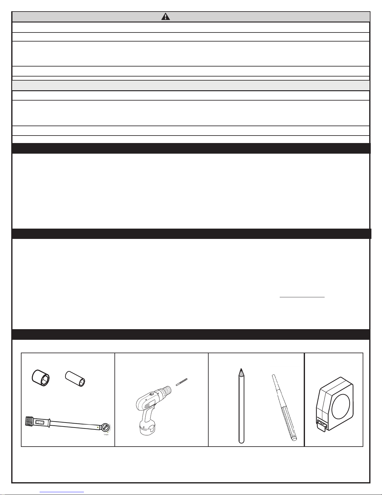
TOOLS REQUIRED
1/2” and 9/16” 23/64” drill bit Grease Pencil or Center
Punch
Tape Measure
©2013 Warn Industries, Inc. WARN® and the WARN logo are trademarks of Warn Industries Inc. 2 91853A0
Page 3
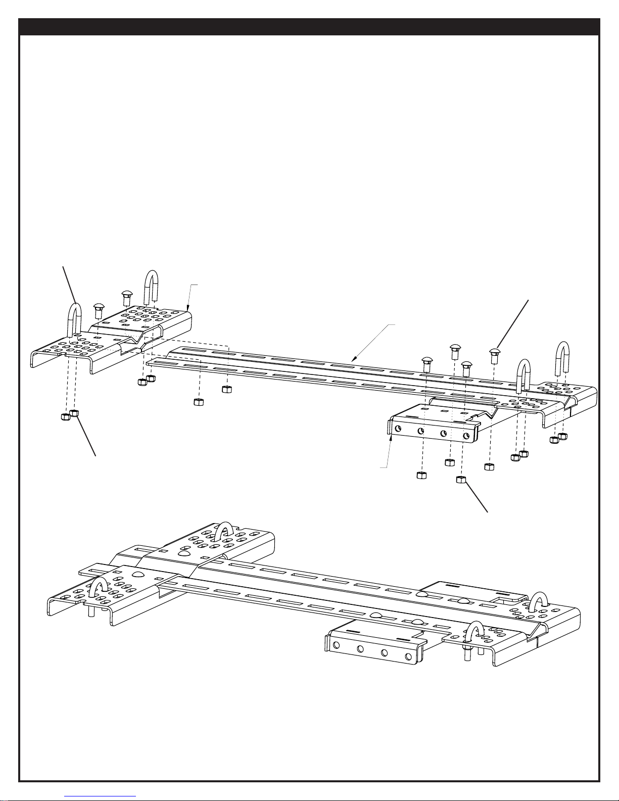
PARTS LIST
Part Number Qty Description
91811 1 PUSH TUBE ATTACH BRACKET
91809 1 ADJUSTABLE REAR CONTACT PLATE
91814 1 SPINE PLATE
63267 6 3/8 16 X 3/4 CARRIAGE HEAD BOLT
6779 6 3/8 16 LOCKING HEX NUT
2002 8 5/16 18 LOCKING HEX NUT
60869 4 5/16 18 X 13/8 X 2” UBOLT
60870 4 5/16 18 X 1 1/4 X 1 3/4” UBOLT (not shown)
61461 4 5/16 18 X 1 1/4 X 2” UBOLT (not shown)
5/16 - 18 X 1-3/8 X 2” U-bolt
5/16 - 18 Locking Hex Nut
Adjustable Rear Contact Plate
Push Tube Attach Bracket
3/8 - 16 x 3/4- Carriage Head Bolt
Spine Plate
3/8 - 16 Locking Hex Nut
Front of Vehicle
Final Assembly Reference
©2013 Warn Industries, Inc. WARN® and the WARN logo are trademarks of Warn Industries Inc. 3 91853A0
Page 4

INSTALLATION INSTRUCTIONS
WARNING
Always use extreme caution when drilling on any vehicle. Make sure that all fuel lines, brake lines, electrical wires, and other objects are not
punctured or damaged when/if drilling on the vehicle. Thoroughly inspect the area to be drilled (on both sides of material) prior to drilling, and relocate any
objects that may be damaged. Failure to inspect the area to be drilled may result in vehicle damage, electrical shock, re or personal injury.
WARNING
WARNING
Always wear safety glasses when installing this kit. A drilling operation will cause ying metal chips. Flying chips can cause eye injury.
Always take time to fully read and understand the installation and Operations Guide included with this product.
1. INSTALLATION 2. INSTALLATION
Factory Skid Plate
Figure 1: Locate skid plate and remove if possible.
Figure 2: Determine proper u-bolt size. U-bolt type must match frame tube cross
section.
3. INSTALLATION
(4) U-bolts
Place two u-bolts near the front end of frame (near or between front a-arms) and two u-bolts in the rear of frame (near or between foot
pegs). The front and rear sets of u-bolts should be no less than 10 inches and no more than 25 inches apart.
Front of vehicle
Front of vehicle
U-bolts 10” - 25” apart
Figure 3: Correct Placement (u-bolts parallel and between 10” - 25” apart).
©2013 Warn Industries, Inc. WARN® and the WARN logo are trademarks of Warn Industries Inc. 4 91853A0
Figure 4: Incorrect Placement - (u-bolts not parallel and over 25” apart)
Page 5

4. INSTALLATION
NOTE: If skid plate is NOT present, skip to step 7.
(1) Spine Plate
(1) Grease pencil or center punch
Front of spine plate less than
19 inches from the front of
the forward facing tires.
<19”
5. INSTALLATION
(1) Adjustable Rear Contact Plate
(1) Grease pencil or center punch
Figure 5: While centering spine plate, align with front u-bolts and mark skid plate
for clearance hole drilling.
6. INSTALLATION
WARNING
that all fuel lines, brake lines, electrical wires, and other objects are not punctured or
damaged when/if drilling on the vehicle. Failure to inspect the area to be drilled may
result in vehicle damage, electrical shock, re or personal injury.
NOTICE
and relocate any objects that may be damaged and then drill clearance holes for u-bolts.
NOTE: During operation, vibration may occur between skid plate and mount. Before installing
Always use extreme caution when drilling on any vehicle. Make sure
Thoroughly inspect the area to be drilled (on both sides of material) prior to drilling,
your plow mount, you may choose to add a sheet rubber isolator between skid plate and
mount, to eliminate excess vibration.
Figure 6: While centering rear contact plate, align with rear u-bolts and mark skid
plate for clearance hole drilling.
7. INSTALLATION
(2) U-bolts
(4) 5/16 - 18 Locking Hex Nut
Figure 8: Insert front pair of u-bolts through skid plate clearance holes and spine
Figure 7: Drill skid plate for u-bolt clearance holes.
©2013 Warn Industries, Inc. WARN® and the WARN logo are trademarks of Warn Industries Inc. 5 91853A0
plate. Loosely attach front end of the spine plate to u-bolts.
Page 6

8. INSTALLATION 9. INSTALLATION
(4) 3/8 - 16 x 3/4- Carriage Head Bolt
(1) Push Tube Attach Bracket
<24”
(4) 3/8 - 16 Locking Hex Nut
Pin Holes
Figure 8: Place push tube bracket against the spine bracket and adjust until a set
Pin Holes
Figure 9: Loosely fasten push tube bracket to spine bracket with carriage bolts and
of pin holes are less than 24 inches from the front of the forward facing tires.
10. INSTALLATION 11. INSTALLATION
(2) 3/8 - 16 x 3/4- Carriage Head Bolt
(1) Adjustable rear contact plate
(2) 3/8 - 16 Locking Hex Nut
locking nuts.
Figure 10: Slide adjustable rear contact plate onto spine plate to align with rear
Figure 11: Loosely secure rear contact plate to spine with carriage bolts.
u-bolts. Do not fasten at this time.
©2013 Warn Industries, Inc. WARN® and the WARN logo are trademarks of Warn Industries Inc. 6 91853A0
Page 7

12. INSTALLATION 13. INSTALLATION
(2) U-bolt
(4) 5/16 - 18 Locking Hex Nut
(4) U-bolt
(8) 5/16 - 18 Locking Hex Nut
(6) 3/8 - 16 x 3/4- Carriage Head Bolt
(6) 3/8 - 16 Locking Hex Nut
Figure 13: Tighten all hardware to torque specications in chart below.Figure 12: Loosely fasten rear contact plate to rear u-bolts with locking nuts.
TORQUE SPECIFICATIONS
Please use the recommended torque specications when assembling this product unless otherwise specied.
FASTENER SIZE FASTENER TORQUE Socket /Wrench Size
lb-ft (N.m)
5/16" U-bolt 17 (23) 1/2” socket
3/8" Carriage Bolt 30 (40) 9/16” socket
PRE-OPERATION SYSTEM CHECK
Perform system check:
1. Verify mount orientation is correct (see nal assembly image on page 3 for reference).
2. Check fasteners and make sure they are tight and to proper torque.
3. Verify that plow blade can rotate freely without interfering with tires or vehicle body. If interference is found, it may be necessary
to adjust the location of the plow mount towards the front of the vehicle.
4. Verify maximum plow lift height to avoid damage to plow mount, push tubes and frame.
Once system check has been performed, you are ready to operate your plow system.
©2013 Warn Industries, Inc. WARN® and the WARN logo are trademarks of Warn Industries Inc. 7 91853A0
Page 8

Figure 14: *Complete mount assembly shown with push tube and plow blade installed.
* Plow Base, Plow Blade and Plow blade-raising mechanism sold separately. For complete plow system options, go
to www.warn.com for the complete line of plow accessories available.
MAINTENANCE / CARE
• Inspect all metal parts on the plow, plow mount, and related hardware. Replace all parts that appear rusted or deformed prior to
use.
• Inspect all nuts and bolts on the plow, plow mount, and related hardware prior to each use. Tighten all nuts and bolts that appear
to be loose. Stripped, fractured, or bent bolts or nuts need to be replaced immediately.
• Check all moving and rotating parts. Remove debris that may inhibit the part from moving freely. Store out of the weather between use to protect against corrosion, freezing and to keep operating smoothly.
SERVICE
1. Refer to these installation instructions for illustrations and detailed information on the installation, safe and proper operation and
assembly diagrams of your Universal Plow Mount. If you are unable to resolve the problem, then go to step 2.
2. Contact your dealer where you purchased your Universal Plow Mount Kit. If, after discussing the problem with their parts and
service sta, you are still unable to resolve the problem then go to step 3.
3. If you are unable to resolve the problem to your satisfaction, please call Warn Industries Customer Service at: 1-800-543-9276. You
may also contact Warn Industries by visiting our website: www.warn.com.
CARELESS INSTALLATION AND OPERATION CAN RESULT IN SERIOUS INJURY OR EQUIPMENT DAMAGE. READ AND UNDERSTAND ALL
SAFETY PRECAUTIONS AND OPERATING INSTRUCTIONS BEFORE INSTALLING AND OPERATING THIS PRODUCT.
©2013 Warn Industries, Inc. WARN® and the WARN logo are trademarks of Warn Industries Inc. 8 91853A0
 Loading...