

Page 1
ORIGINAL INSTRUCTIONS
Winch Installation Guide
Every winching situation has the potential for personal injury. In order to minimize that risk, it is important to read this guide
and The Basic Guide to Winching Techniques carefully. Please familiarize yourself with the operation of your winch before
using it and be constantly safety oriented. In this guide we provide important safety information and instructions on how to
install your winch. Please read the Basic Guide to Winching Techniques for information on how to properly use your winch
and proper rigging techniques.
Please keep this manual and other product literature found in this kit for future reference. In this kit you will find the following
pieces of literature: Winch Installation Guide, Basic Guide to Winching Techniques, Specification and Performance Data,
Product Warranty, Replacement Parts List and other product literature specific to some products.
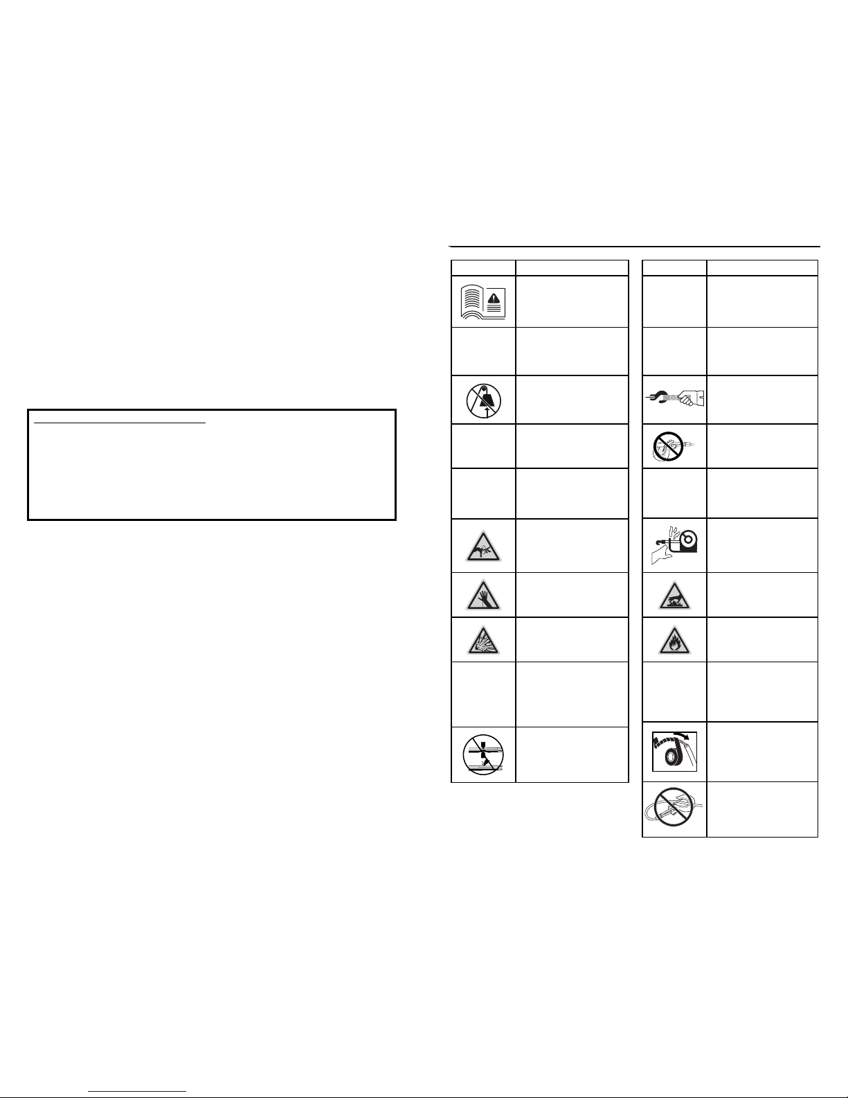
SYMBOL INDEX
SYMBOL EXPLANATION
Read All Product
Literature
Always Wear Hearing
and Eye Protection
Never Use Winch as a
Hoist
Properly Seat Load in
Throat of Hook
Wind Rope on Bottom
of Drum
Finger/Fairlead
Crushing Hazard
Hand Piercing/Cutting
Hazard
Explosion/Bursting
Hazard
Never Route Electrical
Cables through Sharp
Edges Hazard
Avoid Installing
Electrical Cables
around Pinch and Wear/
Abrasion Points
SYMBOL EXPLANATION
Always Wear Leather
Gloves
Do Not Move People
Always Use Supplied
Hook Strap
Never Apply Load to
Hook Tip or Latch
Never Wind Rope Over
Top of Drum
Fairlead Pinch Point
Hot Surface Hazard
Fire and Burn Hazard
Never Route Electrical
Cables through or near
Moving Parts Hazard
Exposed Wiring
Hazard, Insulate
Exposed Wiring and
Terminals
Never Hook Back on
Rope
Page 2
GENERAL SAFETY PRECAUTIONS
As you read these instructions, you will see
WARNINGS, CAUTIONS, NOTICES and NOTES.
Each message has a specifi c purpose. WARNINGS
are safety messages that indicate a potentially
hazardous situation, which, if not avoided could result
in serious injury or death. CAUTIONS are safety
messages that indicate a potentially hazardous
situation which, if not avoided, could result in minor
or moderate injury. A CAUTION may also be used
to alert against unsafe practice. CAUTIONS and
WARNINGS identify the hazard, indicate how to avoid
the hazard, and advise of the probable consequence
of not avoiding the hazard. NOTICES are messages
to avoid property damage. NOTES are additional
information to help you complete a procedure.
PLEASE WORK SAFELY!
Warnings and Cautions
MOVING PARTS ENTANGLEMENT
HAZARD
Failure to observe these instructions could
lead to serious injury or death.
• Always ensure hook latch is closed and not
supporting load.
• Never apply load to hook tip or latch. Apply load
only to the center of hook.
• Never use a hook whose throat opening has
increased, or whose tip is bent or twisted.
• Always use a hook with a latch.
• Always ensure the operator and bystanders are
aware of the stability of the vehicle and/or load.
• Always keep wired remote control lead and
power cord clear of the drum, rope, and rigging.
Inspect for cracks, pinches, frayed wires or loose
connections. Damaged components must be
replaced before operation.
• Always pass remote lead thru window when used
in vehicle.
• Never hook back on rope.
MOVING PARTS ENTANGLEMENT
HAZARD
Failure to observe these instructions could
lead to serious injury or death.
General Safety:
• Always Know Your Winch. Take time to fully read
the Instructions and/or Operations Guide, and/or
Basic Guide to Winching Techniques, in order to
understand your winch and its operations.
• Never exceed winch or winch rope rated capacity.
Double line using a snatch block to reduce winch
load.
• Always wear heavy leather gloves when handling
winch rope.
• Never use winch or winch rope for towing. Shock
loads can damage, overload and break rope.
• Never use a winch to secure a load.
• Never operate this winch when under the infl uence
of drugs, alcohol or medication.
• Never operate this winch if you are under 16 years
of age.
Installation Safety:
• Always choose a mounting location that is
suffi ciently strong to withstand the maximum pulling
capacity of your winch.
• Always use class 8.8 metric (grade 5) or better
hardware.
• Never weld mounting bolts.
• Always use factory approved mounting hardware,
components, and accessories.
• Never use bolts that are too long.
• Always complete the winch installation and hook
attachment before installing the wiring.
• Always keep hands clear of winch rope, hook
loop, hook and fairlead opening during installation,
operation, and when spooling in or out.
• Always position fairlead with warning readily visible
on top.
• Always prestretch rope and respool under load
before use. Tightly wound rope reduces chances of
“binding”, which can damage the rope.
WARNING
WARNING
GENERAL SAFETY PRECAUTIONS
MOVING PARTS ENTANGLEMENT
HAZARD
Failure to observe these instructions could
lead to serious injury or death.
Winching Safety:
• Always inspect winch rope, hook, and slings
before operating winch. Frayed, kinked
or damaged winch rope must be replaced
immediately. Damaged components must be
replaced before operation. Protect parts from
damage.
• Always remove any element or obstacle that may
interfere with safe operation of the winch.
• Always be certain the anchor you select will
withstand the load and the strap or chain will not
slip.
• Always use supplied hook strap whenever
spooling winch rope in or out, during installation
and during operation.
• Always require operators and bystanders to be
aware of vehicle and or load.
• Always be aware of stability of vehicle and load
during winching, keep others away. Alert all
bystanders of an unstable condition.
• Always unspool as much winch rope as possible
when rigging. Double line or pick distant anchor
point.
• Always take time to use appropriate rigging
techniques for a winch pull.
• Never touch winch rope or hook while someone
else is at the control switch or during winching
operation.
• Never engage or disengage clutch if winch is
under load, winch rope is in tension or drum is
moving.
• Never touch winch rope or hook while under
tension or under load.
• Always stand clear of winch rope and load and
keep others away while winching.
• Never use vehicle to pull load on winch rope.
Combined load or shock load can damage,
overload and break rope.
• Never wrap winch rope back onto itself. Use a
choker chain or tree trunk protector on the anchor.
FALLING OR CRUSHING HAZARD
Failure to observe these instructions could
lead to serious injury or death.
• Always stand clear, keep hands clear, keep others
away.
• Never operate winch with less than 5 wraps of rope
around the drum. Rope could come loose from the
drum, as the rope attachment to the drum is not
designed to hold a load.
• Never use winch as a hoist or to suspend a load.
• Always be certain anchor will withstand load, use
appropriate rigging and take time to rig correctly.
• Never use winch to lift or move persons.
• Never use excessive effort to freespool winch rope.
• Always use proper posture/lifting technique or
get lifting assistance while handling and installing
product.
• Always spool the rope onto the drum in the
direction specifi ed by the winch warning label on
the winch and/or documentation. This is required
for the automatic brake (if so equipped) to function
properly.
• Always spool the winch rope onto the drum as
indicated by the drum rotation label.
CUT AND BURN HAZARD
Failure to observe these instructions could
lead to serious injury or death.
To avoid injury to hands and fi ngers:
• Always wear heavy leather gloves when handling
winch rope.
• Always be aware of possible hot surfaces at winch
motor, drum or rope during or after winch use.
WARNING WARNING
WARNING
Page 3
GENERAL SAFETY PRECAUTIONS
AVOID WINCH AND EQUIPMENT
DAMAGE
• Always avoid side pulls which can pile up winch
rope at one end of the drum. This can damage
winch rope or winch.
• Always ensure the clutch is fully engaged or
disengaged.
• Always use care to not damage the vehicle frame
when anchoring to a vehicle during a winching
operation.
• Never submerge winch in water.
• Always store the remote control in a protected,
clean, dry area.
NOTICE
MOVING PARTS ENTANGLEMENT
HAZARD
Failure to observe these instructions could
lead to minor or moderate injury.
To avoid injury to hands or fi ngers:
• Never leave remote control where it can be
activated during free spooling, rigging, or when the
winch is not being used.
• Never leave the winch remote control plugged in
when installing, freespooling, rigging, servicing or
when the winch is not being used.
CHEMICAL AND FIRE HAZARD
Failure to observe these instructions could
lead to serious injury or death.
• Always remove jewelry and wear eye protection.
• Never route electrical cables across sharp edges.
• Never route electrical cables near parts that get
hot.
• Never route electrical cables through or near
moving parts.
• Always place the supplied terminal boots on
wires and terminals as directed by the installation
instructions.
• Never lean over battery while making
connections.
• Never route electrical cables over battery
terminals.
• Never short battery terminals with metal objects.
• Always verify area is clear of fuel lines, fuel tank,
brake lines, electrical wires, etc., when drilling.
• Always consult operator’s manual for proper
wiring details.
• Always insulate and protect all exposed wiring
and electrical terminals.
CUT AND BURN HAZARD
Failure to observe these instructions could
lead to minor or moderate injury.
• Never let winch rope slip through your hands.
CAUTION
WARNING CAUTION
SAFE WORKING CONDITIONS
Safety
When installing your ATV/UTV winch
system, read and follow all mounting and
safety instructions.
Always use caution when working with
electricity and remember to verify that no
exposed electrical connections exist before
energizing your winch circuit.
For specifications and performance data,
refer to the specification sheet supplied with
your winch.
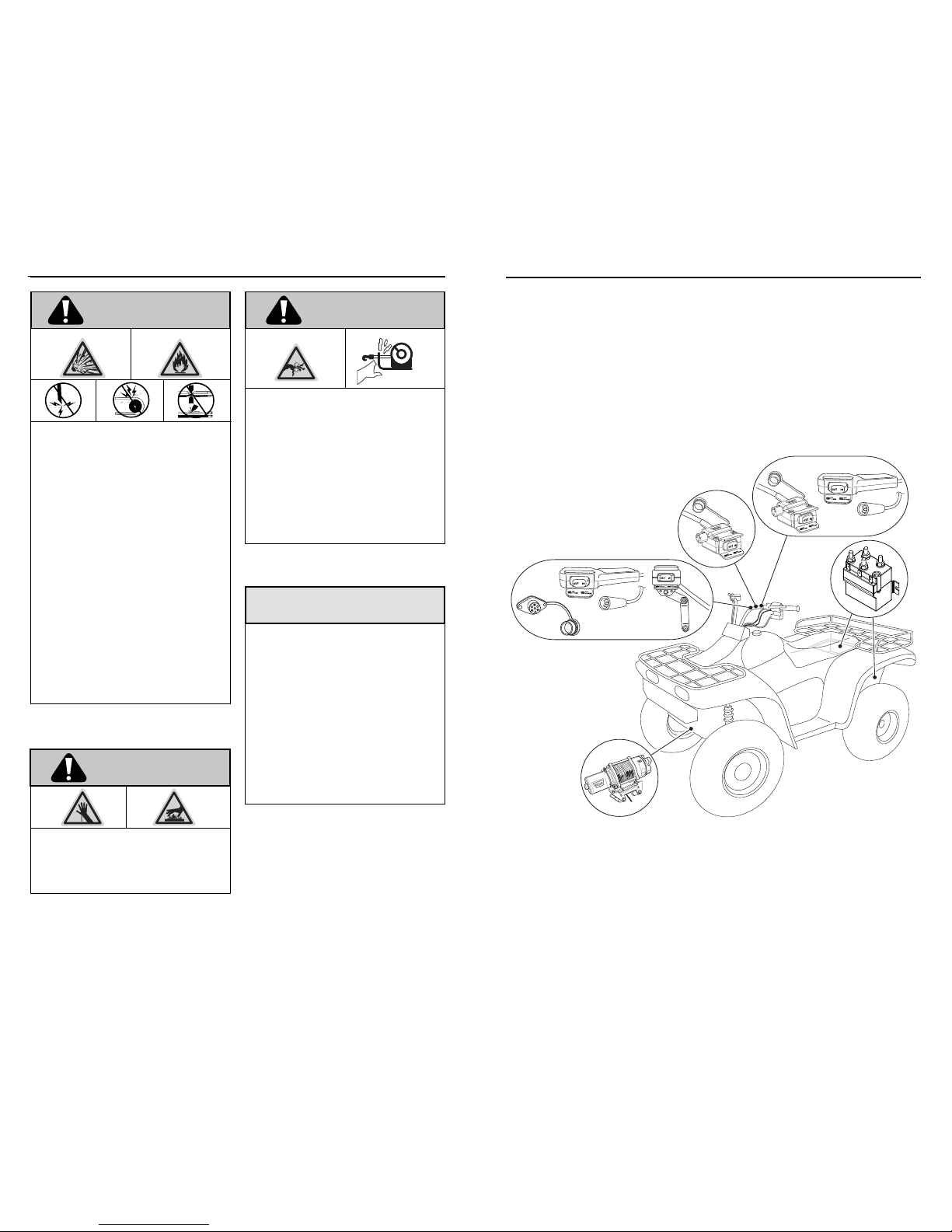
Figure 1: To install the complete kit, you will need to mount the winch, contactor
handlebar mounted Mini-rocker switch and remote socket (optional on some models). Mounting locations may vary depending
on make and model of the ATV/UTV. Read and understand the following instructions to choose the appropriate mounting
locations.
Page 4

MOUNTING
Step 1 - Mount the Winch
ATV/UTV winch mounting kits are available from
your WARN Dealer to satisfy nearly all ATV/UTV
applications. For information on available kits,
contact your WARN product dealer.
NOTE: For optimal performance and the results
you expect, WARN mounting plates are strongly
recommended.
CAUTION
To prevent accidental activation
of the winch and serious injury, complete the winch
installation and attach the hook before installing the
wiring.
To secure the winch, always use:
• A flat, secure mounting location at least 4.8
mm (3/16 in.) thick.
• 8 mm (5/16 in.) Lock washers.
• M8-1.25 X 20 mm, class 8.8 hex head cap
screws when using a one-piece winch mount
plate.
Figure 2 and 3: Orientation of winch to mounting plate and bolt lengths.
20mm25mm20mm
NOTE: When using separate winch mount and
fairlead plates use M8-1.25 X 25 mm class 8.8
hex head cap screws on the motor side of the
base as shown in Figure 3.
1. Set winch in mounting location. Torque the
mounting bolts to 16 N-m (12 lb-ft).
2. Remove bottom tie bolt. This bolt should be
retained for winch service.
3. Remove elastic band retaining rope.
4. Put clutch in freespool position.
5. Manually feed cable loop through fairlead.
6. Attach hook to cable loop and re-engage
clutch.
WARNING
Always use supplied hook strap.
7. Install hook strap on hook.
MOUNTING
Step 2 - Mount the Contactor
•
1.
Your new WARN winch can do a lot of work!
This work is the conversion of electrical power
into mechanical power. The contactor is
the electromagnetic switch that controls the
electrical power to your winch. The contactor
must be correctly installed for it and the winch
to work properly. The following instructions
will assist you in the installation of your WARN
contactor.
Disconnect the vehicle battery cables,
negative terminal first. All work with
electrical wires and cables must be
completed with the battery completely
disconnected from the vehicle wiring.
WARNING
To prevent severe injury or death.
Never lean over battery while making connections.
WARNING
To prevent severe injury or death.
Never route electrical cables over battery terminals.
WARNING
To prevent severe injury or death.
Never short battery terminals with metal objects.
2. It is recommended that the contactor be
mounted close to the battery and in a
location that is as clean and dry as possible.
Figure 4. Contactor for
the WARN ATV/UTV winc
WARNING! Do not mount on or near a heat
source such as engine or exhaust. Ensure the
selected location does not collect or retain
water and the mounting of the contactor
does not block drain holes. Exact location
will vary depending on the ATV/UTV. Typical
locations include inside, on top or on the side
of rear storage box, under the seat or, on a
few models, in front near battery.
3. Ensure the contactor mounting location
selected provides sufficient clearance from
all metal structures such as frame tubes. Do
NOT place tools or other items in a position
that might come in contact with the contactor
posts.
WARNING
To prevent severe injury or death.
Always verify area is clear of fuel lines, fuel tank, brake
lines, electrical wires, etc., when drilling.
4. Drill the mounting holes for the contactor and
proceed to step three. Do NOT mount the
contactor at this time.
Black Terminal
(negative -)
Blue Terminal
(negative -)
Mounting Bracket
Black Spade
Connector
Brown Spade
Connector
Yellow Terminal
(positive +)
Green Spade
Connector
Red Terminal
(positive +)
Page 5

MOUNTING
Step 3- Mount the Handlebar
Switch
WARNING
To prevent serious injury or death from
electrical fi re:
Never route electrical cables across sharp
edges.
Never route electrical cables near parts that
get hot.
Never route electrical cables through or near
moving parts.
Avoid pinch and wear/abrasion points when
installing all electrical cables.
WARNING
To avoid injury and property damage:
Use caution if moving or repositioning the ATV/UTV
controls so as to not compromise the safe operation
of the ATV/UTV. Select a mounting position that will
provide clearance for all vehicle controls.
Before securing the switch cable with tie wraps, make
sure that the handlebars have full range of motion.
1. Switch should be installed on the left
handlebar. A piece of electrical tape around
the handlebar will help prevent rotation of
mount on the handle bar.
2. Do NOT tighten over any hoses or cables.
3. Once the handlebar switch is mounted, route
the wire harness to where the contactor will
be mounted.
4. Using the provided wire splice, splice the
end of the red 20ga wire to a key controlled,
fused, accessory circuit (power-point) of the
ATV/UTV. The wire should only have power
when the key is in the “ON” position.
Figure 5: Handlebar Mount. Exact positioning may vary
depending on the ATV/UTV make and model.
Figure 6: Mini-rocker switch assembly.
Splice and tape
wire together
MOUNTING
Step 4 - Mount the Remote
Socket
(optional on some models)
WARNING
To prevent severe injury or death.
Always verify area is clear of fuel lines, fuel tank, brake
lines, electrical wires, etc., when drilling.
WARNING
To prevent serious injury or death from
electrical fi re:
Never route electrical cables across sharp
edges.
Never route electrical cables near parts that
get hot.
Never route electrical cables through or near
moving parts.
Avoid pinch and wear/abrasion points when
installing all electrical cables.
1. Determine the mounting location for the
remote socket, drill three holes and install
(see Figures 7 and 8).
2. Route the wire harness to where the
contactor will be mounted.
3. Using the provided wire splice, splice the
end of the red 20ga wire to a key controlled,
fused, accessory circuit (power-point) of the
ATV/UTV. The wire should only have power
when the key is in the “ON” position.
NOTE: If installing both switches, both 20 gage
red wires MUST be spliced to a key controlled
accessory circuit of the ATV/UTV as described in
step 4, page 9.
Figure 7 and 8. Remote socket installation
10-24 hex nut &
lockwasher
10-24 hex nut & hex
head capscrew
Keyway must point
down
6.4mm (1/4 in.) diameter, 2 places
22.2mm (7/8in.)
22.2mm (7/8in.) diameter
44.5mm (1-3/4in.)
Not to scale. Do NOT use as a template!
Page 6

MOUNTING
Step 5 - Mount the Dash Switch
(optional on UTV models)
WARNING
To prevent severe injury or death.
Always verify area is clear of fuel lines, fuel tank, brake
lines, electrical wires, etc., when drilling.
WARNING
To prevent serious injury or death from
electrical fi re:
Never route electrical cables across sharp
edges.
Never route electrical cables near parts that
get hot.
Never route electrical cables through or near
moving parts.
Avoid pinch and wear/abrasion points when
installing all electrical cables.
1. Determine the dash mounting location for
the dash switch (location is pre-determined
on some specific models). Mount switch
using bracket and supplied fasteners or cut
rectangle slot as shown in Figure 10.
2. Route the wire harness to where the
contactor will be mounted.
3. See wiring diagram provide, with contactor,
for switch wiring detail.
NOTE: If installing both switches, both 20 gage
red wires MUST be spliced to a key controlled
accessory circuit of the ATV/UTV as described in
step 4, page 9.
Figure 9 and 10 Dash Mount Installation
Not to scale. Do NOT use as a template!
21.1mm
(.83in.)
36.8mm
(1.45in.)
#10x5/8 in. sheet metal screw OR
M5x0.8 hexhead capscrew, M5-0.8
nut, washers.
ELECTRICAL CONNECTIONS
Step 6 - Install the Wiring
WARNING
To prevent serious injury or death.
Always place the supplied terminal boots on wires and
terminals as directed by the installation instructions.
All wires must be attached to the contactor before
mounting the contactor to the ATV/UTV.
WARNING
To prevent serious injury or death from
electrical fi re:
Never route electrical cables across sharp
edges.
Never route electrical cables near parts that
get hot.
Never route electrical cables through or near
moving parts.
Avoid pinch and wear/abrasion points when
installing all electrical cables.
WARNING
Always insulate and protect all
exposed wiring and electrical terminals.
1. Slip terminal boots on yellow and blue cable
ends. See Figure 11 on following page.
2. Attach the yellow and blue electrical cables
to the motor terminals on the winch. Yellow
is marked #1 and blue is marked #2 on the
motor. Torque the terminal nuts on the
motor to 5.7 N-m (50 lb-in). Seat boots over
terminal.
3. Route the yellow and blue electrical cables
back to the contactor. Place boots over
ring terminals. Place ring terminals on color
coded contactor posts (yellow cable to yellow
post, blue cable to blue post). Install and
finger tighten nuts to retain ring terminals
on contactor posts. Do NOT tighten nuts or
seat boots at this time.
6. Install boots on ring terminal ends of red
and black cables. Place ring terminals on
color coded contactor posts (red cable to red
post, black cable to black post). Install and
finger tighten nuts to retain ring terminals
on contactor posts. Do NOT tighten nuts or
seat boots at this time. Route red and black
cables to battery. Do NOT connect cables to
battery at this time.
7. Mount the contactor to the location planned
in Step 3. Tighten contactor mounting
fasteners to 5.7 N-m or 50 lb-in.
8. Adjust cables to facilitate orderly and straight
routing of the cables from the contactor.
Avoid kinks or sharp bends in cables. Avoid
crossing cables over each other for at least
the first 6” (152mm) of cable starting from
the contactor post. Torque the contactor
terminal nuts to 4.5 N-m or 45 lb-in. Seat
boots over ring terminals and posts.
9. Carefully inspect battery and winch
electrical cable routing. Is it neat and tidy?
WARNING! Always route and secure
electrical cables away from sharp edges,
away from moving parts and away
from sources of heat. Zip tie and secure
electrical cables and wiring harness. Zip
ties should be snug, but not cutting into wire
insulation. Use electrical tape, pieces of
rubber hose or electrical conduit to protect
electrical cables and wire harness where
needed to avoid electrical cable insulation
wear or abrasion.
10. Attach battery cables, red (positive) cables
FIRST, black (negative) second. Install
boots as appropriate to protect connection.
Torque battery terminal fastener as directed
by vehicle service manual.
Page 7

ELECTRICAL CONNECTIONS
Figure 11. Wiring Installation diagram
Blue
Black
Red
Yellow
Black
Red
Green
Splice and tape
wire together
Remote optional
SYSTEM CHECK
WARNING
To prevent serious injury or death:
Always spool the winch rope onto the drum
as indicated by the drum rotation label.
Always Wind Rope on Bottom of Drum.
Never Wind Rope Over Top of Drum.
Once you have performed system check.
Turn key switch to ON position and check
winch for proper operation. The rope should
spool in and out in the direction indicated on
the switch.
Check
Before fi rst
operation
After each
use
Every 90 days
Take time to fully read the Instructions
and/or Operations Guide, and/or Basic
Guide to Winching Techniques, in order to
understand your winch and its operations
X
Check fasteners and make sure they are
tight and to proper torque.
Replace damaged fasteners.
XXX
Verify wiring to all components is correct
and be certain that all connections are
tight.
XX
Verify there is no exposed/bare wiring or
terminals.
Cover any exposures with terminal
boots, heat shrink tubing or electricians
tape.
XX
Inspect rope for damage.
Replace rope immediately if damaged.
XXX
Keep winch, rope and switch control
free from contaminants.
Use a clean rag or towel to remove
any dirt and debris.
X
INOUT
 Loading...