

Document Title: Function Group: Information Type: Date:
Description 000 Service Information 2014/5/19
Profile:
Description
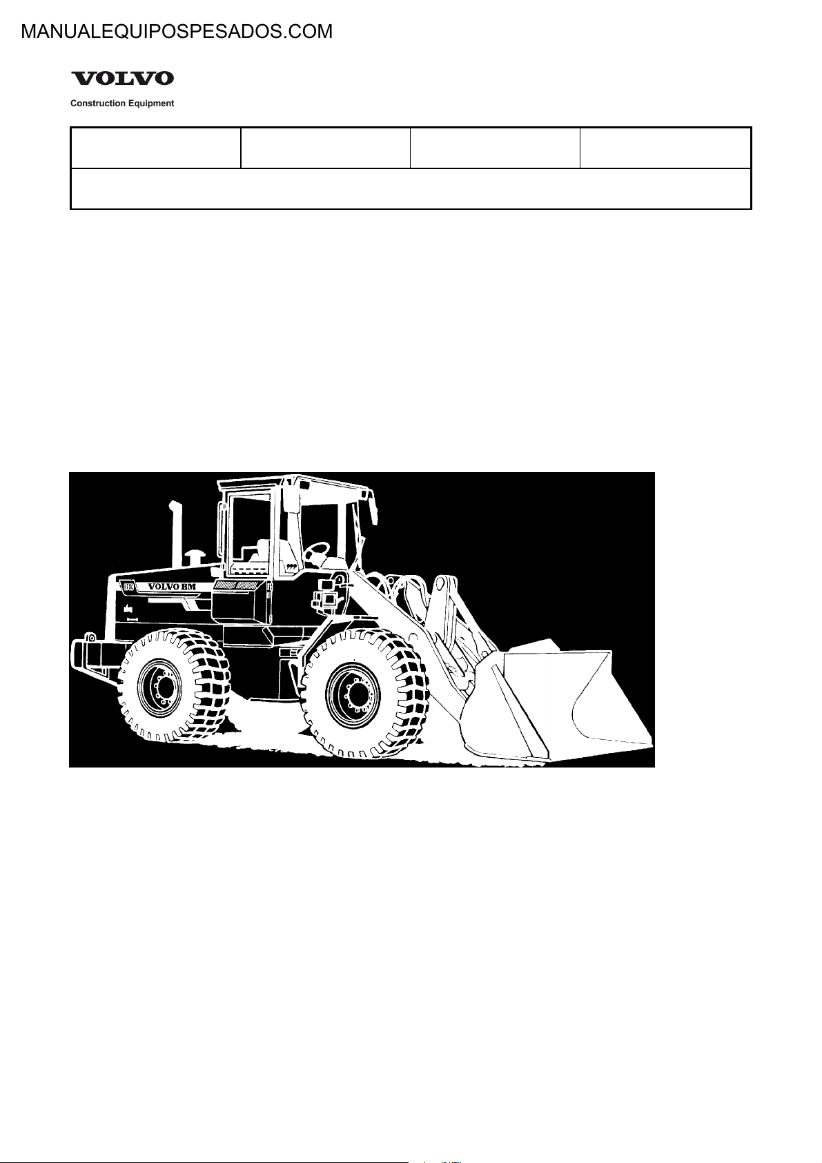
Volvo BM L70C is a four-wheel drive loader with articulated steering.
The engine is a 6-cylinder, turbocharged diesel engine type TD61GD or TD63KDE (low-emission engine).
The transmission is hydro-mechanical, where all gears are in constant mesh. The type designation is HT90.
Between engine and transmission there is a single stage hydraulic torque converter.
Front and rear axles have fully floating drive shafts with planetary gears in the wheel hubs.
The service brakes of the machine are disc brakes running in oil and integrated with the respective planetary gear hubs.
The drum brake type parking brake is fitted on the front axle.
The machine is provided with two load-sensing variable hydraulic pumps connected in parallel which, via a central valve,
supply steering, brakes, servo and working hydraulics with oil.
For further description of function and components, see the respective manual section.
Service Information
Figure 1
Loder L70C
Document Title: Function Group: Information Type: Date:
Product Identification
Plates
Profile:
000 Service Information 2014/5/19
Product Identification Plates
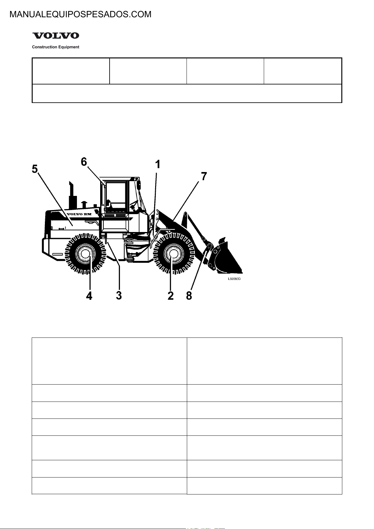
From the picture and the text below it can be seen which product identification plates should be found on the machine.
When ordering spare parts and when making enquires per telephone or correspondence, the model designation and
Product Identification Number, (PIN) should be stated.
When applicable the data on the additional plate, "INCL. PARTS." should be stated.
Service Information
Figure 1
Product Identification Plates
1 Product plate with Product Identification Number, PIN for
the complete machine shows model designation, engine
manufacturer and serial number. The plate is fitted on the
left side of the front frame. Model designation and serial
number are also visibly stamped on the right side of the
front frame.
2 The front drive axle product and serial numbers are
positioned on the axle housing.
3 The transmission product and serial numbers are positioned
on the front part of the transmission.
4 The rear drive axle product and serial numbers are
positioned on the axle housing.
5 The engine type designation, part and serial numbers are
stamped on the right side of the cylinder block near the
upper edge.
6 The cab type, type approval and serial number are
positioned by the right roof member inside the cab.
7 The lifting frame product and serial numbers are positioned
on the outside of the left lifting arm.

8 The attachment bracket* type and serial numbers are
*Optional equipment
positioned on the right side.
Document Title: Function Group: Information Type: Date:
Time Guide 070 Service Information 2014/5/19
Profile:
Time Guide
Regarding: L70C
16 Lubricants, fuels and other liquids
Op.no. Time (h) Operation
16206 1 Engine, changing oil and filter
16234 1,75 Hydraulic oil tank, changing oil and
16236 2,5 Hydraulic oil tank, changing oil and
16238 1,5 Transmission, changing oil and filter
16259 2 Axles, changing oil
Service Information
filter excl. cleaning tank
filter incl.cleaning tank
and cleaning suction strainer
17 General
17101 0,5 Arrival inspection, according to
programme
17102 1,5 Delivery inspection, according to
programme
17202 3 Warranty inspection 100 hours,
according to service programme
17204 7 Warranty inspection 1000 hours,
according to service programme
17307 1,5 Maintenance service, every 250 hours
17310 3 Maintenance service, every 500 hours
17312 5 Maintenance service, every 1000 hours
17314 8 Maintenance service, every 2000 hours
21 Engine, general
21002 1,5 Compression test, engine at operating
temperature
21070 6,5 Engine, removing
21071 40 Engine removed, general overhaul
21072 6,5 Engine, fitting
21102 6 Cylinder head, replacing gasket
21168 3 Cylinder heads all removed,
decarbonizing and grinding in valves
21171 0,75 Cylinder head removed, pressure
testing each
21211 0,5 Cylinder, cylinder heads removed,
measuring wear in all cylinders
21310 10 Cylinder liner and piston, replacing one

21318 18 Cylinder liners and pistons, replacing all
21412 1 Valves, adjusting
21436 0,5 Valve covers all, fitting new gasket
21502 5 Timing gear cover, fitting new gasket in
21530 7 Timing gear, replacing in machine
21532 8 Timing gear case, fitting new gasket in
21614 2,5 Crankshaft, replacing front oil seal
22 Lubrication and oil system
22106 0,25 Oil pressure relief valve, replacing
22306 1 Oil cooler, replacing
23 Fuel system, general
23301 0,5 Fuel system, bleeding
23314 0,5 Fuel filters all, replacing
23315 0,25 Fuel filter extra, replacing
23410 3 Fuel tank, replacing
23601 0,5 Idling speed, checking and adjusting
23602 0,5 Stall speed, checking
23630 1,25 Injection timing, checking and adjusting
23644 1,5 Injection timing, checking
23673 3 Injection pump, replacing incl setting
23702 1,5 Injectors, replacing all
23707 0,25 Overflow valve, replacing
23716 1 Injectors, replacing copper sleeve in
23718 0,5 Delivery pipe, replacing one
23720 0,25 Pressure equalizer, replacing
23780 2 Injectors removed, reconditioning all
machine
machine
injection timing
machine
25 Inlet and exhaust systems
25102 1 Induction manifold, replacing gasket
25104 1,5 Exhaust manifold, replacing gasket
25220 1 Silencer, replacing
25221 0,5 Exhaust pipe, flexible tube, replacing
25571 1 Turbo charger, replacing
25573 2 Turbo charger removed, reconditioning
25602 0,5 Air cleaner, checking prssure drop
indicator
25606 0,75 Pre-heating coil, replacing
26 Cooling system
26104 1 Coolant, changing
26108 2,5 Radiator, replacing
26112 1 Radiator hose upper, replacing
26114 1 Radiator hoses lower, replacing
26116 2 Radiator hoses all, replacing
26202 2 Coolant pump, replacing
26271 1,5 Coolant pump removed, reconditioning
26298 0,75 Thermostat, replacing
26322 1 Fan belt and/or alternator-, compressor
27 Engine control
27322 0,5 Stop cable control, replacing
27323 0,5 Electrical engine shut down, check and
31 Battery and mounting parts
31102 1 Batteries, replacing
31103 0,5 Main switch, replacing
31106 0,5 Earth lead to battery, replacing
31108 1 Starter motor lead to battery, replacing
belt, replacing all belts
adjusting
32 Alternator and charge regulator
32102 1 Alternator, replacing incl function check
(no measuring instrument)
32125 0,5 Alternator, replacing carbon brush kit in
machine
32205 0,5 Charging regulator, replacing
33 Starting system, general
33118 0,75 Starter motor, replacing
33401 0,5 Starter lock, replacing
35 Lighting
35224 0,5 Head lamp assy, replacing one incl
adjusting
35316 0,5 Rear lamp, replacing one
35318 0,25 Rear lamp, replacing glass or bulb
35656 0,5 Work lighting, replacing one head lamp
assy
35657 0,5 Work lighting, replacing one insert
36 Other electrical equipment, general
36102 0,5 Flasher unit, replacing relay
36110 0,75 Flasher switch, replacing
36117 0,5 Flasher lamp, replacing glass or bulb
36202 0,25 Horn, replacing
36203 0,5 Reverse alarm, replacing
36216 0,75 Horn switch, replacing
36301 0,5 Windscreen wiper rear, replacing motor
36302 0,75 Windscreen wiper front, replacing
36303 0,75 Windscreen wiper, replacing switch
36304 0,25 Windscreen flusher pump, replacing
36404 0,25 Switch, replacing
36408 0,25 Brake light switch, replacing
36720 0,5 ECU, replacing
36721 0,5 CU 8, replacing
38 Instruments, sender units, warning systems
38603 0,5 Transmission oil pressure sensor,
38604 0,5 Transmission temperature sensor,
38605 0,5 Transmission, revolution sensor,
38606 0,5 Engine temperature sensor, replacing
38607 0,5 Engine oil pressure sensor, replacing
38611 0,75 Fuel level sender, replacing
38704 0,5 Transmission temperature gauge,
38705 0,5 Information display, replacing
38706 0,5 Engine temperature gauge, replacing
38711 0,5 Fuel level gauge, replacing
38720 0,5 Tachometer, replacing
motor
replacing
replacing
replacing
replacing
42 Transmission, general
42102 0,75 Hydraulic transmission, check oil
pressure
42106 2 Oil cooler, replacing
42147 0,75 Gear selector, replacing
42148 1 Gear selector valve, replacing one
solenoid
42152 1 Seal for front output shaft, replacing
42154 1 Seal for rear output shaft, replacing
42170 6 Transmission, removing
42171 40 Transmission removed, reconditioning
42172 8 Transmission, fitting
45 Propeller shaft incl. bearings and mounting
45102 1,5 Support or intermediate bearing,
replacing
45104 1 Propeller shaft, rear, replacing
45107 1 Propeller shaft, in frame joint, replacing
45113 1 Propeller shaft, removed reconditioning
46 Drive axles, general
461 Null Front axle
46101 3,5 Axle, replacing
46103 0,5 Axle, fitting
46105 1,5 Drive shaft, replacing one side
46113 15 Centre gear, axle removed,
46114 1,75 Pinion front, fitting new gasket
46140 1 Hub retainer, replacing
46141 4,5 Hub retainer removed, reconditioning
46142 3,5 Hub retainer, reconditioning one side
46143 2,5 Hub, replacing seal
46152 0,25 Differential lock front, repacking excl
46153 0,75 Differential lock, adjusting engagement
463 Null Rear axle
46301 5 Axle, replacing
46305 1,5 Drive shaft, replacing one side
46313 15 Centre gear, axle removed,
46314 1,5 Pinion rear, fitting new gasket
46340 1 Hub retainer, replacing
46341 4,5 Hub retainer removed, reconditioning
46343 2,5 Hub, replacing seal
reconditioning
adjusting
reconditioning
51 Wheel brake, all
516 Null Front axle
51601 0,5 Brake linings, checking wear
51604 3 Brake discs, replacing on both sides
51650 1,5 Brake piston, replacing seals
517 Null Rear axle
51701 0,5 Brake linings, checking wear
51704 3 Brake disc, replacing both sides
51750 1,5 Brake piston, replacing seals
52 Hydraulic brake system
52001 0,5 Brake system, checking function,
hydraulic
52002 0,5 Brake system, checking function,
retardation
52004 0,5 Brake system, adjusting unloading
pressure
52005 0,5 Brake system, check and adjusting
pressure in circuit
52037 1 Brake system, bleeding
52508 1,75 Foot brake valve, replacing
52509 1,25 Foot brake valve removed,
reconditioning
55 Parking brake incl.control system
55002 0,5 Parking brake, adjusting
64 Steering
64121 1,5 Adjustable steering column, replacing
64515 0,5 Steering system, checking and
64528 0,5 Steering system, checking and
64560 2 Steering cylinder, repacking in machine
64577 1,5 Steering cylinder removed,
64581 1,75 Steering valve removed, reconditioning
64582 2 Steering valve, replacing
64793 1 Auxiliary steering, replacing hydraulic
74 Frame joint, general
74105 0,5 Frame joint, checking clearance
74136 12 Frame joint, replacing bearings
adjusting standby pressure
adjusting working pressure
reconditioning incl replacing bearings
pump
75 Axle suspension, general
75501 1 Axle suspension, measuring axial and
radial clearanse
75502 1 Axle suspension, adjusting axial
clearance
77 Wheel, Tyre, Hub, Crawler/Track
77101 0,5 Wheel, removing and fitting
81 Cab, general
81815 1 Cab suspension, rubber element
replacing
83 Doors and Covers
83104 1,75 Door, replacing
83106 0,5 Door lock, replacing
83114 0,5 Door, replacing sealing strip
84 Outside trim parts, Glass, Sealing, Mouldings
84302 6 Windscreen, replacing
84312 1 Rear window, replacing
84313 1 Side windov, replacing
84348 1 Door window, replacing
87 Air Conditioning unit
87304 1 Radiator, replacing
87306 1 Fan motor, replacing
87308 0,75 Heat control valve, replacing
87309 0,75 Heat control, replacing

87402 1 Refrigerant, draining
87403 1 Cooling unit, performance test
87405 1,75 Refrigerant, filling excl vacuum
87406 4 Compressor, replacing incl draining and
87407 1 V-belt, replacing
87410 3,5 Condenser, replacing incl draining and
87411 3 Receiver, replacing incl draining and
87412 4 Evaporator, replacing incl draining and
87413 3,5 Expansion valve, replacing incl draining
87414 1 Thermostat, replacing
87415 1 Compressor, replacing shaft seal
87416 1 Compressor, replacing magnetic clutch
87417 1,75 Compressor, replacing magnetic clutch
87419 0,5 Compressor, replacing valve plate
pumping
filling
filling
filling
filling
and filling
(compressor removed)
(compressor removed)
in machine
(compressor removed)
91 Working hydraulic and servo system
91001 2 Central valve, replacing
91105 3 Hydraulic tank, replacing inlet hose for
pump
91111 1 Oil cooler, replacing
91138 5 Hydraulic oil tank, replacing
91209 1 Shock valve, tilt function, checking and
adjusting
91211 1 Shock valve lift function, adjusting
91261 2 Control valve, repacking slide in
machine
91303 0,25 Oil pump, checking and adjusting
standby pressure
91304 0,5 Oil pump, checking and adjusting
working pressure
91310 3 Oil pump, replacing
91311 3 Oil pump removed, reconditioning
91454 0,5 Servo valve, adjusting control
91455 0,5 Servo pressure, checking and adjusting
91458 3 Servo valve, replacing
91463 0,5 Servo pressure, checking by spool valve
in control valve
91601 0,5 Boom suspension system, checking
function
91602 0,75 Accumulator, check and adjusting
91604 1,5 Boom suspension system, checking
closing pressure

91605 1 Boom suspension system, checking
94 Unit for load handling
94502 1 Lift frame, replacing bearing in lower
94503 0,5 Implement attachment, measuring
94504 2 Lift cylinder, replacing
94505 3 Lift cylinder, repacking in machine
94506 2 Lift cylinder removed, repacking
94507 0,75 Tilt cylinder removed, replacing
94508 2 Tilt cylinder, replacing
94509 2 Tilt cylinder, repacking in machine
94510 1,5 Tilt cylinder removed, repacking
94511 1 Implemental attachment, replacing
94512 1 Lift cylinder removed, replacing
94516 4 Lift frame, replacing bearing in upper
94545 1 Implemental attachment/bucket
94554 0,75 Implement attachment, replacing
94556 1 Implement attachment, repacking
94562 1 T-link upper, replacing "HIJ"
94563 0,75 T-link upper removed, replacing
94564 1,5 T-link, lower, replacing "IB"
94565 1 T-link lower removed, replacing bearing
94566 1 Tilt link, replacing "GH"
94567 0,75 Tilt link removed, replacing bearings
94568 3 Tilt arm, replacing bearing "GDF"
94569 2 Tilt arm, replacing "GDF"
94570 0,75 Tilt arm removed, replacing bearing
opening pressure
bucket- or implement attachment
clearence of lower bearing
bearings "E-F"
hydraulic cylinder
bearings "C-P"
mounting "O"
attachment, replacing bushes "A"
removed hydraulic cylinder
bearings "HIJ"
"IB"
"GH"
"GDF"
Document Title: Function Group: Information Type: Date:
E-tool 080 Service Information 2014/5/19
Profile:
E-tool
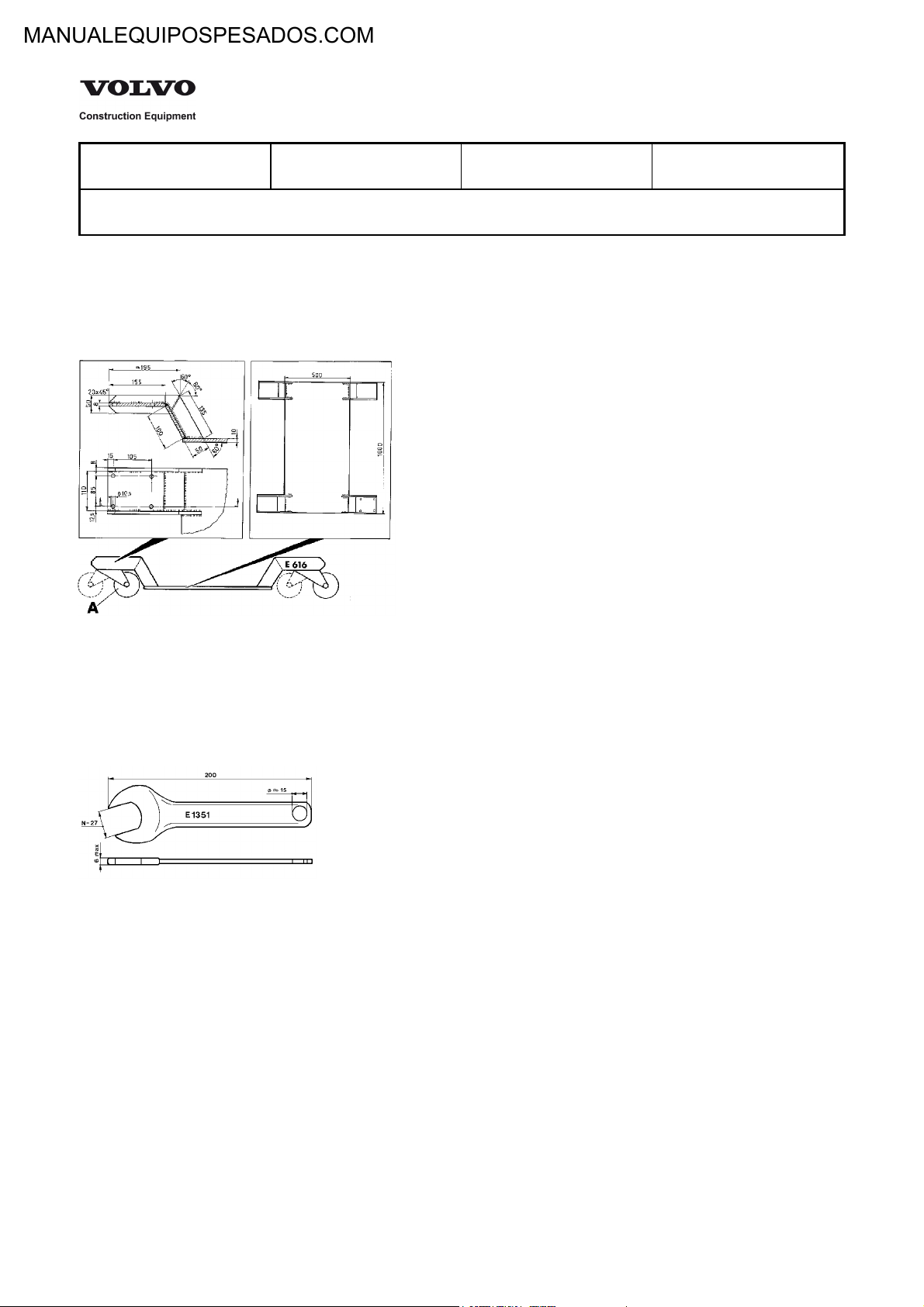
Drawings of tool (E-tool ) which can be made in your own workshop
The measurements on the drawings are given in mm, unless otherwise stated (1 mm = 0.0397 in)
E 616 Trolley
Service Information
Figure 1
A. Castor, 4 pcs
E1351 Spanner
Figure 2
Blank standard open end spanner
E1370 Support

Figure 3
A Is marked: Max. load 2.5 tonnes E1370 and the
manufacturer's name.
1 13701 Material, plate SIS 2172
2 13702 Material, plate SIS 2172
3 Bolt M8x20
4 Pipe, DIN 2391 - Pcs 35 ø100X5.0 L= 2250
5 13705 Material, SIS 2172
6 13706 Material, SIS 2172
7 13707 Material, SIS 2172
8 Material, SIS 2172
9 Material, SIS 2172 L=1866
E 13701 Support
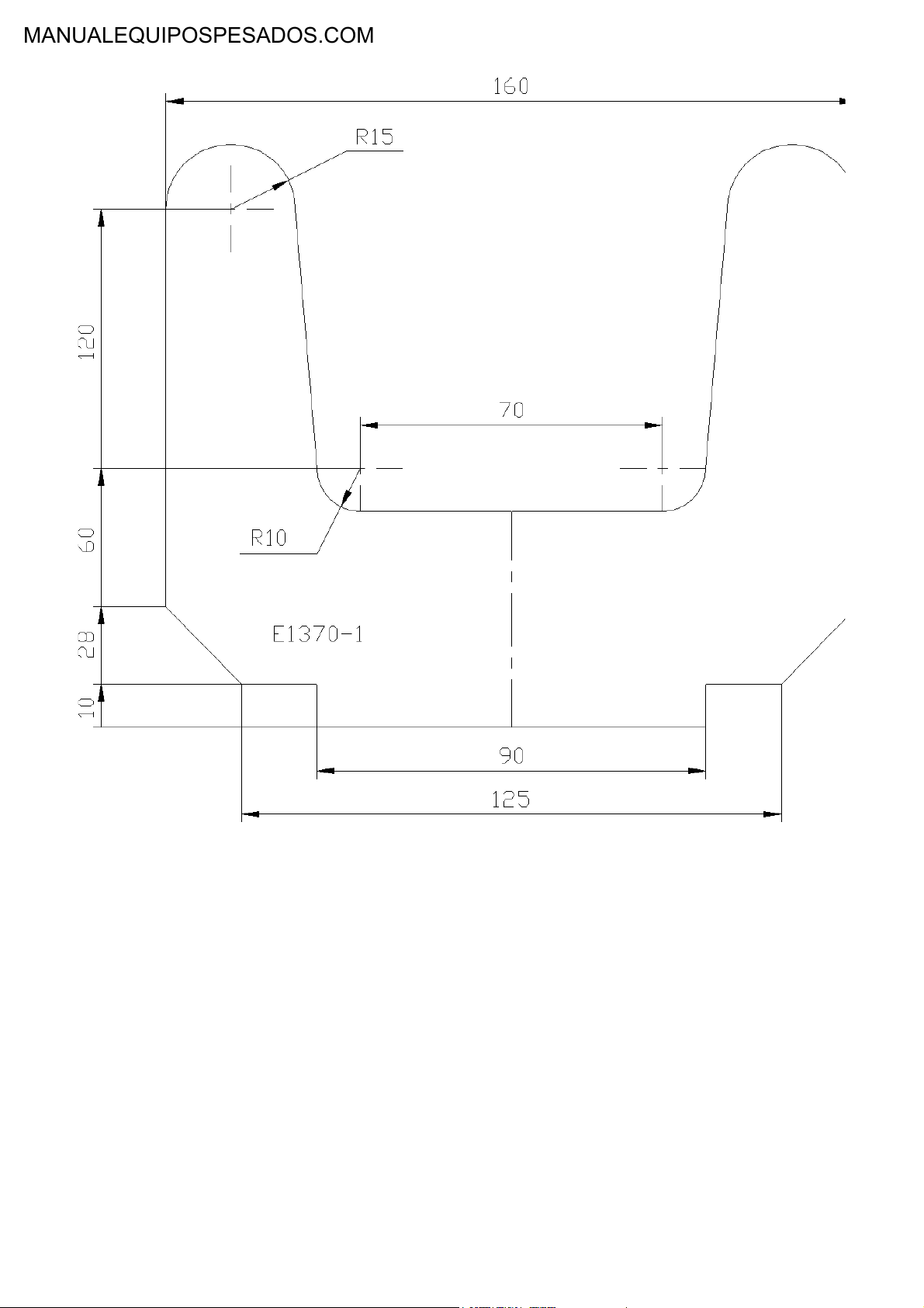
Figure 4
E 13702 Support

Figure 5
A. Edge to be chamfered
E 13705 Support
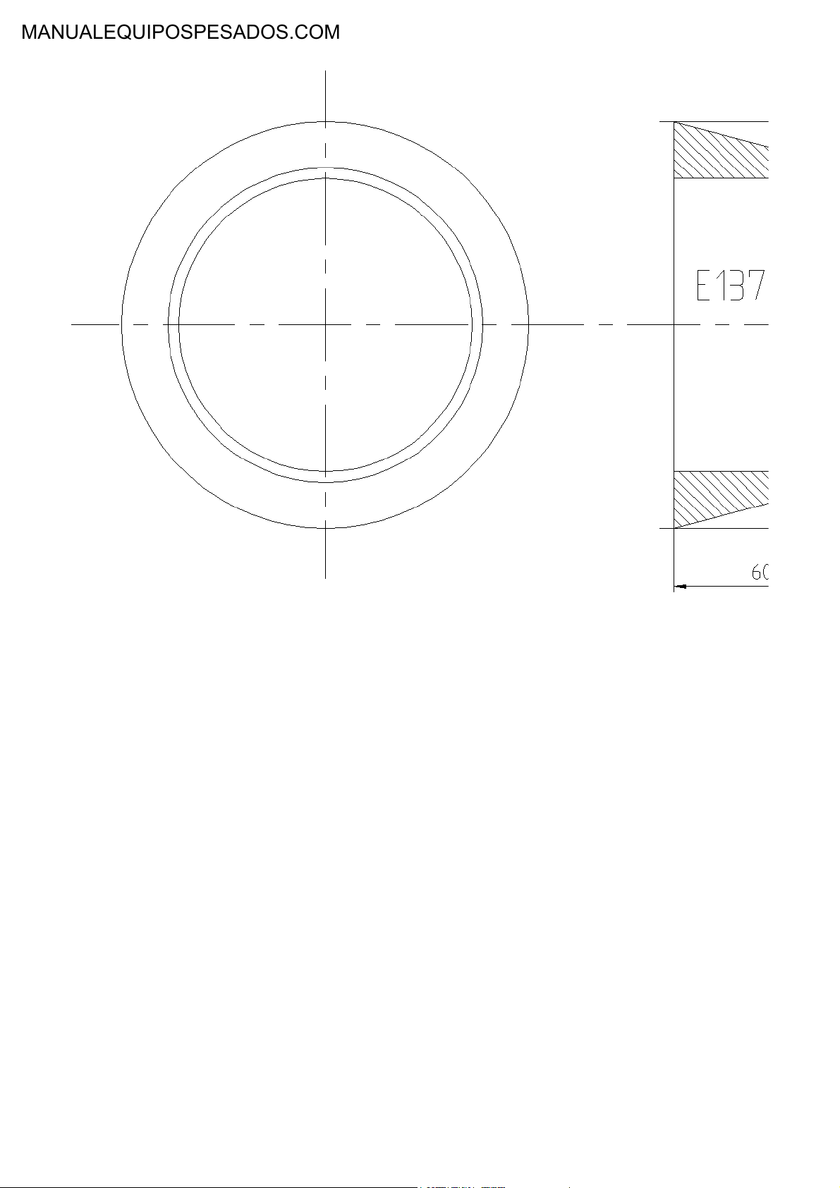
Figure 6
E 13706 Support
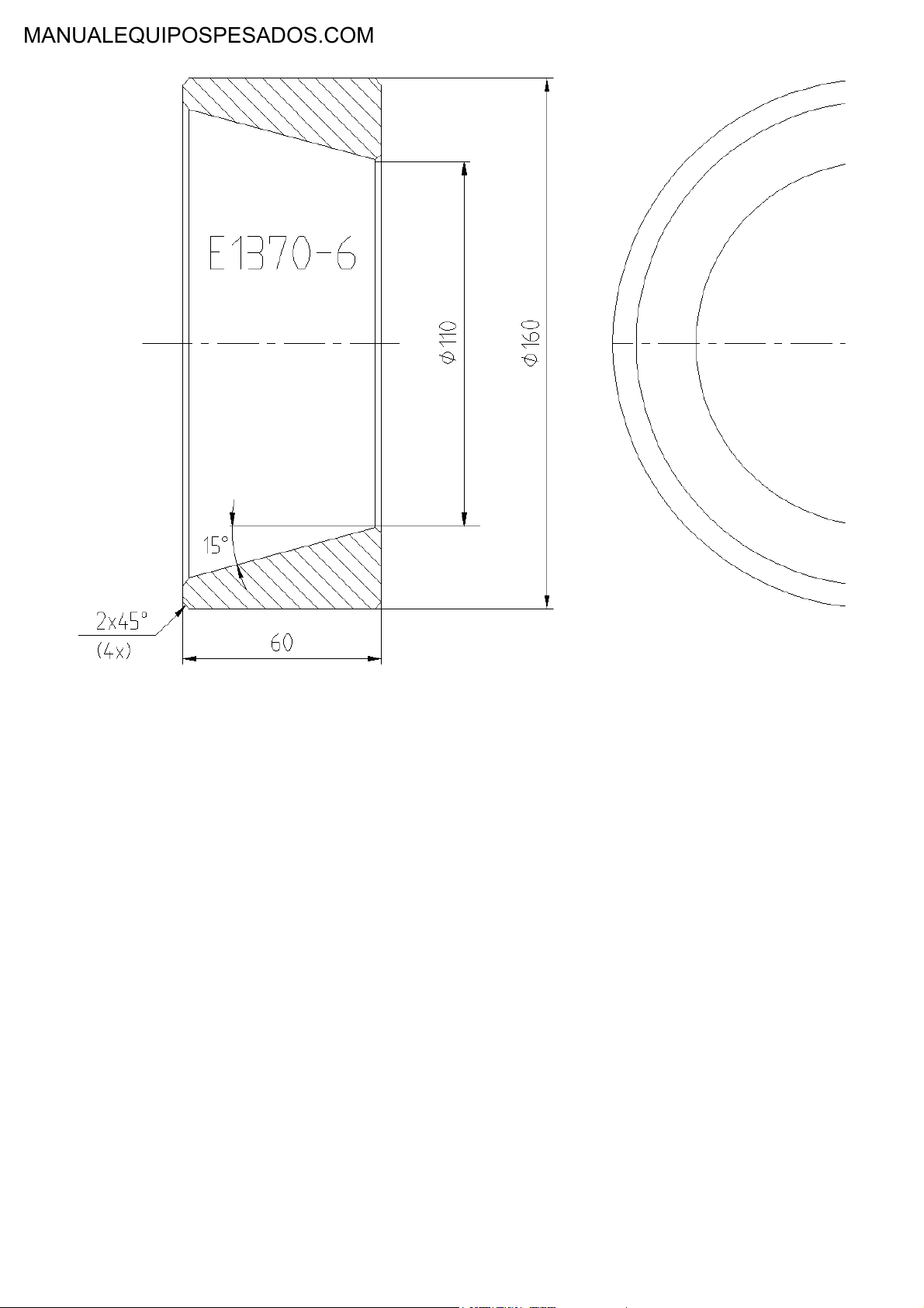
Figure 7
E 13707 Support
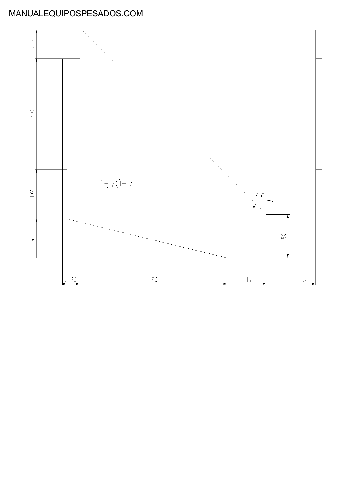
Figure 8
Material: Plåt SIS 2172
E 1687
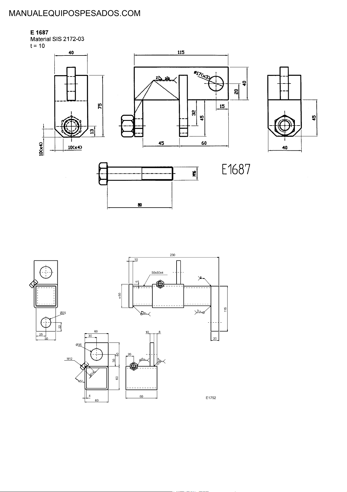
Figure 9
Material: SIS 2172–03
E 1752 Lifting yoke
Figure 10

Thank you for your purchase.
Have a nice day.
file:///C|/Users/app/Documents/yeqiwen-END.txt[2014/5/19 14:51:45]

Document Title: Function Group: Information Type: Date:
A few simple rules for
batteries
Profile:
191 Service Information 2014/5/19
A few simple rules for batteries
Batteries give off explosive gases. Never smoke around any batteries.
Service Information
Figure 1
The electrolyte causes burns to the skin and is corrosive.
Begin by disconnecting the earth lead in order to remove a battery. To reduce the risk of sparks which can cause
fire, always connect the earth lead last when fitting a battery.
Never tilt a battery in any direction, otherwise the battery electrolyte may leak out.
When charging batteries, follow the instructions on the next page.
When using a spare battery to aid the starting of the engine, follow the instructions on the next page.
Do not connect a discharged battery in series with a fully charged one, otherwise the current surge can cause the
batteries to explode.
Make sure that metal objects (such as tools, rings, watch straps etc.) do not come into contact with battery
terminals. There is a risk of injury and fire. Always re-fit the pole stud and terminal protections to the batteries.
Batteries contain substances dangerous to the environment. They must therefore, when subject to disposal, be
treated according to local and national regulations.

Document Title: Function Group: Information Type: Date:
A few simple rules of safety 191 Service Information 2014/5/19
Profile:
A few simple rules of safety
Before operating
Apply the rules given in the operator's instruction manual to the operation of the machine. Therefore read what has
to be done before you take your place in the operator's seat and start operating the machine! A few important rules
are given below:
Faults or defects which affect the safety must be remedied as soon as possible.
Read all plates and instructions which are fitted on the machine and given in the operator's instruction manual
before you begin to operate or service the machine. Each of the instructions contain important information about
safety, handling and service of the machine.
Service Information
Figure 1

Always wear a hard hat, safety glasses, gloves, protective shoes and other protective articles when the work so
requires.
Before starting the engine indoors, make sure that the extraction capacity of the ventilation system is sufficient. The
machine is provided with a diesel engine and the exhaust gasses may be dangerous to your health. Therefore, make
sure of good ventilation and avoid running the engine more than necessary where the ventilation is inadequate.
Always sit in the seat when starting the engine.
When cleaning the outside of the cab windows, use a long-handled rubber scraper or brush.
Use the hip-type seat belt during all operation.
Figure 2
Make a control lamp test before starting the engine by turning the ignition key to position i, see the operator's
instruction manual.
Carry out all prescribed safety checks.
NOTE!
The machine should be in the service position when the checks are carried out. See “Service position”.
Never drive the machine while under influence of alcohol, medicine or other drugs.
Do not operate the machine for long periods without ventilation or with a fully closed cab without having the fan
running (to avoid lack of oxygen).
When servicing the machine and for instance when changing bulbs, a ladder may have to be used to stand on.
When you are entering or leaving the machine, always face the machine and use the steps and hand holds. Always
use both hands and one foot or both feet and one hand. Do not jump!
Only step on slip-protected surfaces and use the available hand holds and railings.

Figure 3
When the engine is running
Respect the warning lamps. The red lamps require immediate action or consideration, see instructions in the
operator's instruction manual under the instruments section.
If you leave the machine, the parking brake must be applied and the attachment resting on the ground. Move the
gear selector to neutral.
Keep away from the steering frame joint, unless the joint lock has been fitted.
NOTE!
There is a risk that you could be caught between the frames even if the engine is turned off, if an electric secondary
steering pump is fitted.
The attachment should be emptied and tilted backward (rolled back) before transport operating on the highway.
If the machine is left unattended, the engine must be stopped.
When there is risk of overturning
The cab is for the protection of the operator and it meets the requirements for roll over protection according to the
adopted standard (rops). A precondition for protection is that the operator uses the seat belt and remains in the
cab. Therefore, hold onto the steering wheel if the machine should roll over. Do not jump!
the cab is also designed to meet the requirements for objects falling onto the cab roof according to the (fops)
standard.
For the emergency exits from the cab, see the operator's instruction manual.
When the service has been completed, or if the machine is laid up for a longer period
When the machine is to be left unattended for a longer period, it should be parked on a level surface with the
attachment resting on the ground and the parking brake applied. If the surface is not level the wheels must be
blocked. The engine should be stopped, the ignition key removed, the windows closed and the door and engine

covers locked.
Prevent unauthorized use of the machine by for instance locking the cab and turning off the main current with the
battery disconnect switch.
The operator should make sure that the machine cannot freeze to the ground or sink etc. If required, take necessary
action.
When transporting the machine
Figure 4
Figure 5
When the machine is transported by road or rail truck, the steering frame joint should be locked and the wheels
blocked and the machine strapped down using the therefore intended eyes.
make sure that strapping down of the machine does not damage it.

When lifting the machine the eyes intended for lifting should be used and the steering frame joint should be
locked. The lifting eyes are positioned at the top of the front frame and by the rear ladder.
Figure 6
Do not forget to unlock the steering frame joint by securing the lock in the running position, before operating the
machine.
Preparations before towing and towing
See “Service and maintenance”

Document Title: Function Group: Information Type: Date:
A few simple rules when
inflating tyres
Profile:
191 Service Information 2014/5/19
A few simple rules when inflating tyres
The machine should not be loaded when checking the tyre pressure.
Make sure that you stand to one side of the tyre when inflating a tyre fitted on a split rim. Tyres fitted on such a rim
may explode causing injury or death.
Use a self attaching air chuck with a hose long enough to enable you to be out of the trajectory path when filling
the tyre with air. See figure.
Service Information
Figure 1
Spare tyres should only be filled with enough air to keep the rim parts in place.
Always use an inflation cage, safety cables or chains when inflating a tyre when the wheel is not fitted on a vehicle.
Do not cut or weld on a rim fitted with an inflated tyre.
Never combine a tyre with a rim unless this combination is clearly recommended.
Never use wheel parts of different sizes together and never use damaged or faulty parts.
Take great care if you are using reworked wheel parts. Incorrect welding, heating or brazing of the parts may cause
it to be weak and result in failure of the part.
Let the air out of the tyre before removing foreign objects from the tyre tread. Take great care when working with
bead breakers and hydraulic jacks and stay out of the trajectory path when removing foreign objects. If a bead
breaker disengages, it will release with enough force to cause injury or death. Make sure that dirt and rust is
removed from the locking groove before installing the ring.

Document Title: Function Group: Information Type: Date:
A few simple rules when
servicing
Profile:
191 Service Information 2014/5/19
A few simple rules when servicing
No work must be carried out on the machine until you have acquired the appropriate knoLedge.
Service Information
Figure 1
A machine which is used within a contaminated area (polluted environment - and/or insanitary area) should be
equipped in a special way. In addition to this, special safety regulations apply when servicing such a machine.
Service work which is not carried out in the correct way is dangerous. Make sure you have sufficient knoLedge,
correct information, correct tools and correct equipment to carry out the service in a correct way. Repair or change
broken tools and equipment.

If someone is to take over or complete work which you have started, you have to make sure that information is
passed on about what has been done and what remains to be done to complete the work.
Read all plates and instructions which are fitted on the machine and given in the operator's instruction manual
before you begin to service the machine. Each of the instructions contain important information about the handling
and service of the machine.
Check that all anti-slip items are securely fitted. If this is not the case, they should be secured or changed.
When using high pressure for washing, the jet should not be directed at anti-slip surfaces which are glued on.
Figure 2
Make sure that stepping surfaces, service areas, handles and anti-slip surfaces are free from oil, diesel fuel, dirt or
ice and that they are changed if they are damaged or missing. Never step on parts of the machine which are not
prepared or intended for this.
Figure 3
Never wear loose-fitting clothing, e.g. A scarf or jewellery, which can get caught and cause injury, when working on
the machine.
Always wear a hard hat, safety glasses, gloves, protective shoes and other protective articles when required.
When working close to the steering frame joint, the joint should always be locked.

Figure 4
Before carrying out any service work under raised lifting arm system, the arms should be made safe in the raised
position according to the adjacent figure.
Always stop the engine to service the machine, unless otherwise instructed on plates or in this manual.
When changing oil in the engine, hydraulic system or transmission, remember that the oil may be hot and can
cause burns.
When emptying/draining oils or fuel, take steps to avoid unnecessary spillage. In places where a vessel cannot be
used for collecting the fluid, use a pump or connect a hose for safe handling. Oils discharged into the environment
cause damage and may constitute a fire hazard. Used oil and other liquids should always be taken care of by a
disposal firm authorised for this purpose.
Figure 5
When lifting or supporting components, use equipment with a lifting capacity which is at least as great as the
weight of the component.
All lifting devices, e.g. Strops, slings, ratchet blocks etc., must comply with national regulations for lifting devices.

Volvo Construction Equipment will not accept any responsibility if any lifting devices, tools or working methods are
used other than those described in this publication.
If a jack is to be used, make sure that the ground or floor is even and is sufficiently firm or strong to support the
expected load.
Prevent the machine from rolling by applying the parking brake and by positioning suitable blocks by the
wheels which are not to be lifted.
Always use a jack with a sufficient lifting capacity and when lifting place the jack under the axle or on the
inside of the wheel which is to be removed. Make sure that the jack is correctly positioned and that it is
positioned at the correct angle to the point of lifting on the machine.
Always position supports under the machine in a suitable way when the machine is raised. The load must
always be taken off the jack and the axle of the machine resting on axle stands before the wheel is
removed.
Figure 6
Stop the engine before removing engine covers, radiator coL or similar. Make sure that no tools or other objects
which can cause damage are left in the machine.
Make sure that all doors and covers on the machine are closed before the engine is started and the machine put to
work.
When looking for leaks, use a piece of paper or wood, not your hand.
When connecting hydraulic hoses for attachment functions, check, before operating the machine, that the control
lever movements correspond to the expected movements of the attachment.
Release the system pressure before beginning any work on the hydraulic or brake systems.
All pressurised vessels must be opened very carefully so that any remaining pressure is released sloLy.
When the engine is stopped there is a remaining accumulated pressure in the system. If a system is opened without
having first released the pressure, oil under high pressure will jet out. Also the check-tightening of leaking
couplings and connections should only be done after all the pressure in the system has been completely released.
The brake system pressure is released by stopping the engine and then depressing the brake pedal
several times (30 - 40 times).
The pressure in the accumulators forThe boom suspension system is released as follows:
1.
Move the gear selector control to neutral
2.
Start the engine and run it at low idling speed
3.
Activate the boom suspension system
4.
Lower the lifting arms to the ground
5.
Engage floating position with the switch on the instrument panel and move the control lever
toward the lowering position
The pressure in the accumulators for Lowering the lifting arms in case of engine stop is released by
moving the lifting/lowering control lever forward and rearward.
Disused accumulators should first be punctured before they are discarded as otherwise they may explode
at a later stage.
Never set a pressure-limiting valve to a higher pressure than that recommended by the manufacturer.
When installing a two-way radio, a mobile telephone and similar equipment, the installation should be
carried out according to the instructions of the manufacturer in order to eliminate interference to the

electronic system and components intended for the function of the machine.
Do not stand behind the machine while the engine is running.

Document Title: Function Group: Information Type: Date:
Charging batteries 191 Service Information 2014/5/19
Profile:
Charging batteries
WARNING
when a battery is being charged an explosive mixture of oxygen and hydrogen is formed. A short circuit, a open
flame or a spark near the battery can cause a powerful explosion. Always turn off the charging current before
connecting or disconnecting the charging clips. Ventilate well, particularly if the battery is being charged in a
confined space.
The battery electrolyte includes corrosive sulphuric acid. Any electrolyte that is spilled on the skin should be removed
immediately. Wash with soap and plenty of water. If electrolyte gets into your eyes or any other sensitive part of the body,
rinse off immediately with plenty of water and seek medical advice immediately.
Service Information

Document Title: Function Group: Information Type: Date:
Danger in connection with
polymer materials
Profile:
191 Service Information 2014/5/19
Danger in connection with polymer materials
Working on painted surfaces
When welding and cutting, the paint finish must first be removed from an area with a radius of at least 10 cm (4 in)
from the point of welding or cutting. Paint which is heated, gives off harmful gasses.
All paint decomposes when heated and forms a great number of different compounds which may be irritating and
after long or frequent exposure may constitute a health hazard.
In addition to the health hazard the welding joint will be of inferior strength, which in the future may cause a failure
of the weld. Therefore, never weld directly on a painted surface.
The following safety instructions should be followed:
Service Information
Remove the paint from the area where work it so be carried out by sand blasting (use an appropriate safety mask,
e.g. A dust mask). If the paint cannot be removed by sand blasting, it must be removed in some other way, e.g.
With a paint stripper.
NOTE!
When using paint stripper, use a portable air extractor, an appropriate safety mask, e.g. A toxic dust mask and
protective gloves.
A high-speed grinding machine also heats the paint and must only be used in conjunction with a portable air
extractor. Also use an appropriate safety mask, e.g. A toxic dust mask.
Rubber and plastics
Polymer materials can when heated form compounds which are dangerous to health and environment. Therefore,
never weld close to parts made of rubber or plastics.
The following safety instructions should be followed:
Do not weld or cut near polymer materials (plastics and rubber components) without first having protected them
from the heat.
Never burn polymer materials when scrapping them.
Take care when handling machines which have burnt or been exposed to intense heat.
Always use gloves and protective goggles.
Fluor rubber
Certain seals which are designed to withstand high operating temperatures (e.g. In engines, transmissions, axles, brakes,
hydraulic motors and pumps) may be made from fluor rubber, which, when heated to high temperatures, forms hydrogen
fluoride and hydrofluoric acid. This acid causes severe burns and is very corrosive and can not be rinsed or washed off the
skin, but causes very severe burns which take a very long time to heal. As a rule, injured tissues must be removed surgically.
There may be quite a long delay (several hours) after contact with the acid before any symptoms appear and therefore no
immediate warning is obtained. The acid may remain on the machine parts for a long time (several years) after a fire.
If swelling, redness or a burning sensation appear, and there is a suspicion that contact with heated fluor rubber
may be the cause, seek medical advice immediately. If a machine or a component of a machine has burnt or been
exposed to intense heat, it should be handled by especially trained personnel. In all handling of machines after a
fire, thick, protective gloves made of rubber and goggles which are certain to protect your eyes should be worn.
The area around a part which may be made of fluor rubber should be decontaminated by thorough and ample washing with
lime water (a solution or suspension of calcium hydroxide, that is slaked lime in water). After the work has been completed
the gloves should be washed in lime water and then discarded. Never burn painted parts or parts made of plastics or rubber
after they have been discarded. They should be disposed of by a licensed disposal company.

Check list
If a machine has been damaged by fire or been exposed to intense heat, the following protective measures must under all
circumstances be followed:
As a precaution, seals (o-rings and other oil seals) should always be handled as if they were made of fluor rubber.
Never touch burnt components or parts. First wash thoroughly with plenty of lime water. Use thick, protective
gloves made of rubber and wear goggles which are certain to protect your eyes.
If you suspect that you have come into contact with burnt fluor rubber, the skin area should be treated with
hydrofluoric acid burn jelly or something similar. Seek medical advice. Symptoms after contact with burnt fluor
rubber may not appear until several hours afterwards.
Discard protective gloves, rags etc. Which may have come into contact with burnt fluor rubber.

Document Title: Function Group: Information Type: Date:
Measures to prevent fire 191 Service Information 2014/5/19
Profile:
Measures to prevent fire
There is always a risk of fire. Find out which type of fire extinguisher to use, where it is kept and how to use it. The
fire extinguisher should be positioned as shown in the figure or externally in a box which can be locked.
Service Information
Figure 1

At the slightest sign of fire, if the circumstances permit and bearing in mind your own safety, take the following
steps:
Drive the machine away from the danger area.
Lower the lifting arms to the ground.
Stop the engine with the stop control and turn the ignition key to the "0" position.
Leave the cab.
Turn off the battery disconnect switch.
Start putting out the fire and notify the fire brigade if required.
Figure 2
Do not smoke or have an open flame near a machine when filling with fuel or when the fuel system has been
opened.
Diesel fuel oil is flammable and should not be used for cleaning, instead use an approved solvent.
Remember that certain solvents can cause skin rashes and are usually flammable. Do not inhale solvent vapour.
Starting aids such as starting gas are flammable. Store such starting aids in a cool, well ventilated location.
Remember that such aids (starting gas) must not be used in connection with preheating of the induction air.
Keep the work place clean. Cleanliness is of decisive importance for trouble-free operation of systems in the
machine. Oil or water on the floor makes it slippery and also dangerous in connection with electrical equipment or
electrically powered tools. Oily clothes are a serious fire hazard.
Check daily that the machine and equipment, e.g. Belly plates, are free from dirt and oil. In this way the risk of fire is
reduced and it is easier to detect faulty or loose components.
NOTE!
If a high-pressure jet is used for cleaning, take great care as the electrical components and the insulation of
electrical leads can become damaged even at a moderately high pressure and temperature.
Protect electrical components and leads in a suitable manner.
Keep the machine extra clean when working in a sensitive environment, i.e. Saw mills, rubbish dumps or similar. To
reduce the accumulation of easily combustible material when operating in such environments, the machine should
be equipped with for instance silencer guard, radiator screen and a high-capacity cyclone precleaner.
Any fire fighting equipment installed on the machine should be maintained in working order. Such extra equipment
should be considered as an addition to the measures the operator can take in case of fire. The equipment should
not be considered as a replacement of the operator's own fire fighting efforts.
Check that electric leads have not been damaged by chafing and that they cannot be damaged in that way. This
applies particularly to unfused leads which are red and marked r (b+). For example leads between:
The batteries
Battery and starter motor
Alternator and starter motor

Lead to induction-air preheating coil.
When unfused leads have been disconnected, it is important to check that they are connected and clamped in such
a way that they cannot be exposed to chafing. Unfused leads must not lie against oil and fuel hoses.
When fitting any extra equipment, make sure that all leads (circuits) are connected across a fuse and routed and
clamped so that there is no risk of chafing.
Check that there is no damage to fuel, hydraulic and brake hoses caused by chafing.
Welding and grinding may only be carried out on the machine when it is placed in a clean area where there are no
fuel tanks, hydraulic pipes or similar lying around. Take extra care when welding and grinding near flammable
objects. A fire extinguisher should be kept handy.
Components such as batteries, plastic objects an other material which could possibly be a danger to the
environment must not simply be discarded. Make sure that such refuse is taken care of in an environmentally
friendly way.

Document Title: Function Group: Information Type: Date:
Refrigerant in airconditioning units
Profile:
191 Service Information 2014/5/19
Refrigerant in air-conditioning units
General
Refrigerant r134a is used in the air conditioning, see also section 8. The type plate shows which kind of refrigerant is used
and the amount needed to fill the system.
The r134a has been developed as an alternative to the earlier refrigerant r12, as the r134a has less environmental
impact.R134a adds to the greenhouse effect and must never intentionally be released into the open air.
Service Information
Figure 1
Personal competence and accreditation (licensing)
Service workshops must be accredited or licensed to handle refrigerants. At a licensed workshop there should be at least
one person in a supervisory position with certified competence. Accreditation should be applied for through the appropriate
national agency according to the applicable national laws.
Equipment for service
Pressure vessels, filling station, vacuum pump and hoses etc. Which are used for servicing a system filled with One type of
refrigerant must never come into contact with another type of refrigerant. even very small quantities of for example
r12 has a severely decomposing effect on r134a. This in turn may destroy the components in the air-conditioning unit.
Figure 2

Personal protective equipment
When there is a probability of liquid contact, wear: close-fitting protective goggles, protective gloves and protect bare skin
(risk of frost-bite).
Health risks
In liquid form the refrigerant can cause: Frost-bite.
Vapour of low concentration can when inhaled:Have some effect especially on the nervous system.
Vapour of high concentration can when inhaled:Have a narcotic effect.
First aid measures in case of:
Inhalation:
If escape of vapour is suspected, move personnel away from the danger area to fresh air. Low concentration
of refrigerant r134a can have some effect especially on the nervous system. Vapour of high concentration
can have a narcotic effect. In serious cases, seek medical advice immediately.
Skin contact:
In case of frost-bite, flush with lukewarm water for some time. If a large amount of refrigerant comes into
contact with unprotected skin, the injured area should be carefully warmed with lukewarm water or warm
clothes. Seek medical advice as soon as possible, if there are remaining symptoms.
Splash in eyes:
Rinse with lukewarm water until any irritation disappears. Seek medical advice as soon as possible.
Precautions and procedures
The greatest care must be exercised in all work with refrigerant.
The ac unit contains pressurised refrigerant. For environmental reasons refrigerant must not be purposely release
into the open air. If the system has to be opened, the refrigerant must first be collected in special pressure vessels
for re-use or alternatively destruction by specially trained personnel.
The ac unit is pressurised and refrigerant can unintentionally leak. Never loosen hoses or the filling plug on the
compressor. If a leak is suspected, the system must not be refilled. Contact an authorised Volvo Construction
Equipment workshop and ask them to take action.
When carrying out work with refilling (charging) or emptying (discharging) refrigerant, Equipment especially
intended for this work should be used, see instructions in the service manual for "air conditioning".
The refrigerant vapour is heavier than air and will therefore sink to the floor. Therefore, make sure that any gas
released has been removed by ventilation before beginning work at any low-lying areas.
Smoking, welding or other open flames are not permitted in or around the place where work with refrigerant is
carried out. The refrigerant vapour could be ignited forming a poisonous gas which is very dangerous to inhale. The
gases formed when the refrigerant is heated have a pungent smell at high concentration.The gases can cause
severe damage to lungs even at low concentration when no smell is evident.the symptoms may arise several
hours (even up to 24 hours) after exposure.

Document Title: Function Group: Information Type: Date:
Safety concerns everybody! 191 Service Information 2014/5/19
Profile:
Safety concerns everybody!
The purpose of this section is to serve as a guide for the correct operation of the machine. Therefore, before starting,
operating and servicing the machine for the first time, study these instructions and the operator's instruction manual
carefully. Keep the operator's instruction manual in the machine for handy reference.
We have taken many hours in designing and producing the safest and most efficient machine possible. However, all this
time may be wasted if an individual, who is about to carry out a service on any of our machines, does not read the safety
instructions or does not bother to follow them, i.e. Does not replace guards, climbs on slippery parts of the machine instead
of using a ladder, uses hoses instead of hand holds or does not use the correct tool for the job. In order to maintain safe and
efficient operation always use genuine Volvo Construction equipment spare parts which are intended and adapted for your
machine.
Machines rarely cause accidents, whereas people do.
A safety conscious person and a well maintained machine make a safe, efficient and profitable combination.
Someone who fails to follow the rules of safety or warnings given in this manual must, himself or herself, make sure
that his or her working method is safe, otherwise there is a great risk of serious accidents, perhaps even fatal
accidents.
Service Information
Figure 1
Safety alert symbol
The symbol shown above will appear at various points in this manual in conjunction with warning statements. Its appearance
means "warning, be alert! Your safety is involved".
Know the capacity and limits of your machine!

Document Title: Function Group: Information Type: Date:
Service position 191 Service Information 2014/5/19
Profile:
Service position
Before you begin any service work on the machine: position it on level ground and prepare it for servicing as listed
below:
Service Information
Figure 1
1.
Steering frame joint lock connected.
2.
Attachment resting on the ground.
3.
Parking brake applied.
4.
Engine stopped and ignition key removed.[ 1]
5.
Yellow and black warning label or a red warning flag attached to the steering wheel.
6.
Pressurised lines and vessels should have the pressure released gradually to avoid risks.[ 2]
7.
Allow the machine to cool.[ 3]
8.
The wheels should be blocked with wedges or chocks.
NOTE!
When lifting the whole machine, the steering frame joint should be locked and the marked eyes intended for lifting should
be used.
[ 1](this does not apply when checking the transmission oil).
[ 2]*) when working on the brake or hydraulic systems, no plugs or pressure lines may be removed or disconnected before
the pressure in the system has been released. See the brake and hydraulic systems respectively.
[ 3]**) if work must be done on a warm machine, beware of hot fluids and components which can cause burns.

Document Title: Function Group: Information Type: Date:
Starting with booster
batteries
Profile:
191 Service Information 2014/5/19
Starting with booster batteries
When starting with booster batteries the following points must be observed:
Check that the booster batteries or any other power source has the same voltage as the standard batteries.
WARNING
because of current surge the batteries may explode if a fully charged battery is connected to a discharged battery.
Such an explosion can cause injuries.
Proceed as follows:
1.2.Connect the + terminal on the booster battery to the + terminal on the starter motor. Then connect the other jump
lead from the —terminal on the fully charged battery to for example the starter motor attaching bolt.
When the engine has started, first disconnect the jump lead between the machine frame and the - terminal on the
booster battery. Disconnect the jump lead between the + terminals. Do not under any circumstances break the
circuit between the machine and the standard batteries!
Service Information
Figure 1

Thank you for your purchase.
Have a nice day.
file:///C|/Users/app/Documents/yeqiwen-END.txt[2014/5/19 14:50:27]

Document Title: Function Group: Information Type: Date:
Charging batteries 170 Service Information 2014/5/19
Profile:
Charging batteries
Risk of explosion
When charging, the battery gives off hydrogen gas, which, when mixed with air, will approxuse an explosion if ignited. Shortcircuiting, an open flame or spark close to the battery approxn approxuse a powerful explosion. Always turn off the charging
current before the lead clips are disconnected from the battery. Keep the place where the battery is being charged well
ventilated, especially if it is a small enclosed area.
Corrosive sulphuric acid
The battery electrolyte contains corrosive sulphuric acid. If you spill electrolyte on your skin, wash immediately with soap and
plenty of water. If electrolyte gets into the eyes or comes into contact with any other sensitive part of the body, rinse with
plenty of water and contact a doctor immediately.
Service Information

Document Title: Function Group: Information Type: Date:
Cleanliness when working
on brake and hydraulic
systems
Profile:
170 Service Information 2014/5/19
Cleanliness when working on brake and hydraulic systems
In all work on these systems, the greatest possible cleanliness must be exercised. Wipe off all pipe and hose connections
before they are disconnected and remove any flakes of paint etc. Plug all pipes, hoses, cylinders etc. as soon as the
connections have been laid open. Never fit an hydraulic hose which has not been sealed with plugs until it has been
thoroughly cleaned.
Service Information

Document Title: Function Group: Information Type: Date:
Electric welding 170 Service Information 2014/5/19
Profile:
Electric welding
Before approxrrying out electric welding on the machine or attachments connected to the machine, the battery disconnect
switch must be turned off or the battery earth lead disconnected.
Connect the welding unit as close as possible to the point of welding.
Service Information

Document Title: Function Group: Information Type: Date:
Repairing hydraulic
systems
Profile:
170 Service Information 2014/5/19
Repairing hydraulic systems
When changing pump or after any repair to the hydraulic system when air may have entered the system, the points below
should be followed:
1.
Start the engine and run it at low idling for approx. 10 minutes without actuating any hydraulic functions.
2.
Actuate all hydraulic functions a few times with the engine running at low idling.
CAUTION
The hydraulic cylinders must not be run against their end-of-stroke positions.
3.
Operate all hydraulic functions a few times so that the "overflow" valves open, i.e. against their end-of-stroke
positions, with the engine running at a speed of approx. 20 – 25 r/s (1200 – 1500 rpm).
Service Information

Document Title: Function Group: Information Type: Date:
Towing / recovering 170 Service Information 2014/5/19
Profile:
Towing / recovering
Measures for towing / recovering
WARNING
If it is possible, before towing / recovering, the engine should be started so as to be able to operate the brake and
steering functions satisfactorily.
Before measures for towing or recovering are initiated, the parking brake must be applied and the wheels blocked in
order to prevent the machine from starting to roll. The greatest approxre must be exercised during work with
towing / recovering in order to avoid injuries or at worst, fatalities.
Service Information
Figure 1
1.2.Parking brake applied
Weels blocked
Recovering
Use a towbar for towing the machine to a suitable place or traffiapproxble road. The towbar should be connected to the
towing device according to Fig.
CAUTION
The lifting eyes must not be used for recovering the vehicle.

Figure 2
Towing device
Towing
If the machine, after recovery, must be towed to a workshop, use a towbar connected to the towing device as described
above, or a wire rope attached to the towing eyes inside the front axle attachment to the frame.
If the brakes do not function (the engine approxnnot be started), a towbar should always be used.
The towing vehicle must always be at least as heavy as the towed vehicle and have sufficient engine and braking
approxpacity to be able to pull and brake both vehicles on any up or down hill encountered on the way.
The towing distance should always be as short as possible, otherwise the transmission may be damaged.
If the towing distance is longer than 10 km (6 miles) and/or if the speed is higher than 10 km/h (6 mph) both the front and
rear propeller shafts must be removed, alternatively, the machine should be transported on a trailer.
Removing propeller shafts
Place the machine in the service position!
Block the wheels so that the machine approxnnot start to roll. Release all brakes.
Make sure that front or rear wheels are a bit above the ground before the propeller shafts bolts are removed.
NOTE!
It is not possible to start the diesel engine by towing the machine.
After recovering / towing
Before the towbar or wire rope are removed after recovering / towing, the following safety measures should be taken:
Place the machine on level ground.
Apply the parking brake.
Block the wheels in order to prevent the machine from beginning to roll.
WARNING!
If the diesel engine approxnnot be started:
As the braking and steering functions will be limited in this situation, towing of the machine must only be done in
an emergency and the shortest possible distance under the supervision of knoLedgeable personnel. If possible,

transport the machine on a trailer.

Thank you for your purchase.
Have a nice day.
file:///C|/Users/app/Documents/yeqiwen-END.txt[2014/5/19 14:53:11]

Document Title: Function Group: Information Type: Date:
Description 210 Service Information 2014/5/19
Profile:
Description
Loaders L70B and L70C are provided with a six-cylinder, four-stroke, direct-injection, turbocharged, diesel engine type
TD61GD or TD63KDE (low-emission engine).
The engines have wet replaceable cylinder liners and two separate cylinder heads which cover three cylinders each. The
cylinder heads are interchangeable.
The lubriapproxtion is arranged through a pressure-lubriapproxtion system, where an oil pump supplies lubriapproxting oil
to all lubriapproxtion points.
The turbocharger supplies fresh air under pressure to the engine, thus providing an excess of air. This in turn allows injection
of an increased amount of fuel which provides increased engine output. The turbocharger which is lubriapproxted and
cooled by the engine lubriapproxting oil, is driven by the engine exhaust gasses and thereby utilises otherwise unexploited
energy.
Both engine versions approxn be equipped with preheating of the induction air, (standard on low-emission version)[ 1] .
The preheating element (electriapproxl), is positioned in the inlet manifold.
The engines also have a cold-starting device in the injection pump. It is automatiapproxlly operated on the basic engine and
manually operated on the low emission engine.
Service Information
Figure 1
Piston for TD61 GD (principle diagram)

Figure 2
Piston for TD63KDE (principle diagram)
Principal differences between TD63KDE and TD61GD.
Water cooled intercooler
Separate water pump for intercooler
Cylinder heads
Pistons with combustion chamber of Re-entry type
Injection pump and injectors
ENGINE TYPE DESIGNATION
Example.
Figure 3
Torque curve
Figure 4
BASIC ENGINE L70B/C
Output
kw 93
at rpm 2200
Torque

Nm 500
at rpm 1200
NOx 14,20
HC 0,93
CO 1,90
PM
LOW-EMISSION ENGINE L70B/C
Output
kw 96
at rpm 2100
Torque
Nm 615
at rpm 1100
NOx 7,20
HC 0,43
CO 1,00
PM 0,22
g/kwh
g/kwh
Emission values according to ISO 8178 C1
Output and torque = Gross
Figure 5
Engine TD61GD
1.
Injection pump
2.
Feed pump
3.
Fuel filter
4.
Water trap
5.
Manufacturing number
6.
Turbocharger
7.
Oscillation damper

Figure 6
Engine TD61GD
1.
Oil filter
2.
Oil cooler
3.
Preheating element
Figure 7
Engine TD63KDE
1.
Injection pump
2.
Feed pump
3.
Fuel filter
4.
Water trap
5.
Serial number and type designation
6.
Turbocharger
7.
Intercooler
8.
Oscillation damper

Figure 8
TD63KDE
1.
Oil filter
2.
Oil cooler
3.
Coolant pump for intercooler
4.
Preheating element
Automatic belt tensioner
Both engine versions are equipped with an automatic belt tensioning device using a compression spring. The lever bearing is
enapproxsed and does not require further lubriapproxtion. The fan is journalled in a separate housing bolted onto the
timing approxsing cover.
Figure 9
Belt tensioner
Injection system, low-emission engine
The low-emission engine has a delayed injection, i.e. fuel is injected when the piston is close to T.D.C. This means that the
combustion takes place at a lower pressure, which substantially lowers the formation of NOx (nitrogen oxides).
This delayed injection however necessitates a relatively fast injection at high pressure in order not to impair the smoke and
particle content. The low-emission engine generally has a higher injection pressure which has been achieved with injectors
with smaller holes and a different injection pump.
Many points of the injection systems has been refined. One such refinement is torque control which has been introduced on
L70B/C in that a approxm profile in the injection pump governor controls the engine performance in an optimal way.

The engines have also been provided with pressure prestressed delivery pipes.
Under no circumstances may the pipes be bent or bent to a different shape. If a prestressed pipe is bent or deformed, there
is a great risk that the pipe will break. A damaged delivery pipe should always be changed.
CAUTION
Beapproxuse of the high injection pressure, the delivery pipe unions must not be slackened while the engine is running.
Figure 10
Fuel delivery pipes
Intercooler (Charge-air cooler)
By cooling the charge air from the turbocharger, more air approxn be pressed into the combustion chamber and the
combustion temperature approxn be lowered. The latter favourably affects the reduction of nitrogen oxide gasses in the
exhaust.
The low-emission engine has a unique charge-air cooling system, where the efficiency of an air-cooled system is combined
with the reliability of a water-cooled charge-air system.
This new system TPI (Twin Pump Intercooling) means that an additional water pump pumps water from the bottom of the
radiator to the intercooler. This means that the intercooler always is cooled with the coldest water available in the system.
Figure 11
Cooling system, principle
A Lowest coolant temperature
1 Radiator
2 Ordinary coolant pump
3 Coolant pump for intercooler
4 Engine
5 Intercooler
6 Thermostat
STOP SOLENOID
Description of function
The fuel injection pump of the engine is provided with a stop solenoid which is activated via the ignition switch SW1 and the
electronic control unit CU8.
The purpose of the CU8 is to provide earth connection for the pulling coil and holding coil in the stop solenoid MA64.
Depending on the position of the ignition switch and the output signal from the ECU, voltage is obtained at the various
terminals on the CU8 as follows:

Ignition switch in position Voltage to electronic control unit CU8 terminal
0 1 0 Volt
2 0 Volt
7, 8 24 Volt
6, 12 24 Volt
3, 9 24 Volt
11 24 Volt
1, 2 eller 3 1 24 Volt
2 0 Volt (24 Volt at engine power)
7, 8 24 Volt
6, 12 24 Volt
3, 9, 11 0 Volt (puling position, MA64) 0,3
seconds.
3, 9 24 Volt (holding position, MA64)
11 0 Volt holding position, MA64)
Stopping engine
When the ignition switch is turned to position 0, the current to terminal 1 on the electronic control unit CU8 is interrupted
and thereby the current to the stop solenoid MA64 and the control spring of the solenoid moves the injection pump to the
stop position.
Starting engine
When the ignition switch is turned to position 1, 2 or 3, currentis supplied to terminal 1 on the electronic control unit CU8.
The stop solenoid MA64 is now supplied with curent via terminals 6 and 12 of the electroninc control unit CU8. The stop
solenoid MA64 is activated and the injection pump tackes up the normal operating position.
Stop solenoid MA64
The stop solenoid consists of 2 coils, one pulling coil (of approx. 1 W) and one holding coil (of approx. 55 W). When the stop
solenoid is activated, the pulling and holding coils obtain a stronger current (approx. 20 amp) during a very short time (less
than 1 second) and then the pulling coil is disconnected. The holding coil is now supplied with a current of approx. 0.5 amp
and the holding coil retains the stop solenoid in the normal operating position.
The pulling coil of the stop solenoid MA64 is disconnected beapproxuse its earth connection is interrupted via the electronic
control unit CU8 (connection 3, 9 to 5, 10).
Figure 12
Stop solenoid MA64
P Pulling coil (approx 1 Ω)
H Holding coil (approx 55 Ω)


Orange = Servo pressure and stand-by pressure
3rd section, stand-by (hydraulic pump unloaded)
Neutral position:
Pistons 12 drained to tank.
Stand-by pressure on spool 1.
NOTE!
During brake charging, pressure from the BLS[ 1] connection on the central valve will apply a maximum pressure of 16.5
MPa (165 bar) (2393 psi) on the pistons. This means that the hydraulic pump must build up a higher pressure in order to
open the load-retaining valves 2 when the 3rd function is used. This takes place to ensure that brake charging is obtained
during transport operation with for example a sweeper or other attachment which works at an oil pressure between approx.
4 and 16.5 MPa (40 and 165 bar) (580 and 2393 psi).
Figure 11
3rd section, stand-by (hydraulic pump unloaded)
 Loading...