


IPS 2
IPS650, IPS800, IPS950
Installation
1(1)
E


Content
Safety Information ......................................................................................
2
General Information .................................................................................... 5
Installation Tools and Documentation ...................................................... 8
Special Tools .......................................................................................... 10
System Information .................................................................................. 13
EVC .......................................................................................................... 13
Engine Characteristics ............................................................................. 14
Engine Application Ratings .................................................................. 14
Engine Performance .............................................................................. 15
Arrangement and Planning ...................................................................... 17
Engine Placement .................................................................................. 17
Engine Room .......................................................................................... 19
Sound Absorption .................................................................................. 30
Electrochemical Corrosion ................................................................... 33
Installation ................................................................................................. 51
Volvo Penta IPS ...................................................................................... 51
Fiberglass Hull Constructions ............................................................ 51
Aluminium Hull Constructions ........................................................... 81
Engine Foundation ............................................................................... 82
Propulsion Unit Installation ................................................................ 87
Engine Installation ............................................................................... 92
Extension Shaft .................................................................................... 96
Exhaust System ................................................................................... 98
Cooling System .................................................................................. 100
Fuel System .......................................................................................... 111
General ................................................................................................ 111
Fuel Tanks .......................................................................................... 112
Piping .................................................................................................. 116
Fuel pressure ...................................................................................... 118
Lubrication System .............................................................................. 119
Electrical System ................................................................................. 120
Batteries .............................................................................................. 121
Alternator ............................................................................................ 130
Voltage Supply ................................................................................... 131
Connection ......................................................................................... 132
Fire Extinguishing System .................................................................. 140
Calibration and Settings ......................................................................... 142
IPS Calibration ...................................................................................... 142
Launching and Sea Trial ........................................................................ 148
Alphabetical index .................................................................................. 155
47704162 10-2014 © AB VOLVO PENTA 1

Safety Information
This installation manual contains information required
for the correct installation of your Volvo Penta product. Check that you have the correct manual.
Carefully read the chapters Safety precautions
and General information in the manual before
servicing or running the engine.
The
following types of special warning messages can
be found in this manual and on the engine:
WARNING!
Indicates
a hazardous situation which, if not avoided,
could result in death or serious personal injury.
IMPORTANT!
Indicates a situation which, if not avoided, could result
in property damage.
NOTICE! Important information that facilitates the
work process or item.
Set out below is a list of risks that must always be
borne in mind and the safety precautions that must
always be taken.
Plan ahead so that there is always sufficient
space for safe installation and (future) disassembly.
Lay
out the engine compartment (and other compartments such as the battery compartment) so that all
service points are accessible. Make sure not to come
into contact with rotating components, hot surfaces or
sharp edges when checking and servicing the engine.
Make sure that all equipment (e.g. pump drives, compressors) has protective covers.
Make sure the engine cannot be started while
work is in progress by not connecting the electrical
system or by switching off electrical power to the
engine at the main switches and locking them in the
OFF
position. Erect a warning sign at the helm station.
Only start the engine in well-ventilated areas.
Remember
that exhaust fumes are toxic and dangerous to inhale. Use an exhaust extractor to lead
exhaust fumes away from the exhaust pipe and crankcase ventilator when the engine is run in a confined
space.
Always wear protective goggles if there is a risk
of splinters, sparks and splashes from acid or other
chemicals. Eyes are extremely sensitive and injury
may result in loss of sight!
Avoid getting oil on the skin! Prolonged or
repeated contact with oil may lead to the disappearance
of the skin's natural oils. This will cause irritation,
dry skin, eczema and other skin problems. Old oil is
more hazardous to health than new. Use protective
gloves and avoid oil-soaked clothes and rags. wash
regularly, especially before meals. Use special skin
creams that facilitate cleaning and prevent the skin
from drying out.
Most chemical used in the product (engine and
reverse
gear oil, glycol, gasoline and diesel) or chemicals intended for use in the workshop (degreasing
agents, paints and solvents) are health hazards. Read
the instructions on the product packaging carefully!
Always follow safety instructions (the use of protective
masks, protective goggles, gloves etc.). Make sure
that other personnel are not inadvertently exposed to
hazardous substances, e.g. in the air they breathe.
Ensure good ventilation. Hand in used and surplus
chemicals to a recycling station.
Take extreme care when searching for fuel sys-
tem leaks and testing injectors. Wear protective goggles. The spray from an injector is at very high pressure and fuel can force its way into tissue and cause
a serious risk of blood poisoning (septicemia).
Stop the engine and disconnect the power at the
main switches before working on the electrical system.
2 47704162 10-2014 © AB VOLVO PENTA

Coupling adjustments must be made with the
engine stopped.
Use the lifting eyes installed on the engine/
reverse gear when lifting off the drive. Always check
that
the lifting equipment is in good condition and has
the capacity to lift the engine (engine weight including
reverse gear and any auxiliary equipment installed).
If the engine has auxiliary equipment that has
altered
its center of gravity, special lifting devices may
be required to obtain the correct balance for safe handling.
Never work on an engine that is suspended in an
engine hoist.
It is mandatory that no work be carried out on a
running engine. There are however adjustments that
require the engine to be run. Approaching a running
engine is a safety risk. Loose clothes and long hair
can
catch in rotating parts and cause serious injury. A
careless movement or a dropped tool may result in
injury when working in the vicinity of a running engine.
Be careful to avoid hot surfaces (exhaust pipes, turbochargers, charge air manifolds, start elements etc.)
and hot liquids in pipes and hoses on engines that are
running or recently stopped. Re-install all protective
covers that were removed during maintenance work
before starting the engine.
Make sure that all warning and information decals
on
the product are always visible. Change decals that
are damaged or painted over
Turbocharged engines: never start the engine
without the air cleaner installed. The rotating compressor
turbine in the turbocharger can cause severe
injury. Foreign objects that enter the inlet ducts can
also cause mechanical damage.
Never use start spray in the air intake. The use
of such products may result in an explosion in the inlet
manifold. Risk of injury.
Do not open the engine coolant filler cap (fresh-
water
cooled engines) when the engine is hot. Steam
or hot coolant may be ejected when system pressure
is released. Open the filler cap slowly and release the
system pressure carefully (freshwater cooled
engines). Hot coolant may spray out if the filler cap or
drain tap is opened, or if a plug or coolant pipe is
removed from a hot engine.
Hot oil can cause burns. Avoid getting oil on the
skin. Be sure to release the pressure from the lubrication system before starting work on it. Never start
or run an engine without the oil filler cap attached.
There is a risk of oil being ejected.
If the boat is in the water – stop the engine and
close
the seawater tap before working on the system.
All fuels, and many chemicals, are flammable.
Make sure they are not exposed to open flames or
sparks.
Gasoline, certain solvents and hydrogen from
batteries are extremely flammable and explosive in
the right concentration in air. No Smoking! Make sure
the workplace is well ventilated and take the necessary safety precautions before welding or grinding in
the vicinity. Always have a fire extinguisher accessible
at the workplace.
Store oil, fuel-soaked rags and old fuel and oil
filters in the correct manner. Oil-soaked rags may
ignite spontaneously in certain conditions. Old fuel
and
oil filters are harmful to the environment and must
be handed to a recycling station for destruction.
Make sure the battery compartment is built
according to current safety standards. Never allow
open flames or electrical sparks in the vicinity of the
batteries.
Never smoke in the vicinity of the batteries.
Batteries give off hydrogen gas during charging,
which may combine with air to form an explosive mixture. The gas mixture is extremely volatile and easily
ignited. Incorrect battery connection may cause
sparks which in turn may cause an explosion. Do not
change the battery connections when attempting to
start the engine (risk for sparks) and do not lean over
the batteries.
Safety Information
47704162 10-2014 © AB VOLVO PENTA 3

Make sure that the positive (+) and negative (–)
battery cables are correctly connected to the corresponding battery terminals. Wrong connection may
cause severe damage to electrical equipment. Refer
to the wiring diagram.
Always wear protective goggles when charging
or handling batteries. Battery electrolyte contains
highly corrosive sulfuric acid. Wash immediately with
soap
and copious amounts of water if battery electrolyte comes into contact with the skin. Flush immediately with water and seek medical attention if battery
acid gets in the eyes.
Never work alone when installing heavy compo-
nents, even when using safe lifting equipment e.g.
lockable blocks. Most lifting devices require the two
people, one to take care of the hoist and the other to
make sure no components catch or are damaged.
The components in the electrical system, ignition
system (gasoline engines) and fuel system on Volvo
Penta products are designed and manufactured to
minimize the risk of fire and explosion. Do not run
engines
in areas where there are explosive materials.
Always use fuels recommended by Volvo Penta.
Refer
to the Operator's Manual. Poor quality fuel may
damage the engine. Poor fuel quality in a diesel
engine may cause the fuel control mechanism to bind
which will lead to engine overspeeding with the risk of
engine damage and personal injury. Low fuel quality
may also lead to higher service costs.
Use an adjustable lifting beam to provide a safe
lift and to avoid damage to components on the top of
the engine. All chains and cables must run parallel
and
be as square as possible to the top of the engine.
Safety Information
4 47704162 10-2014 © AB VOLVO PENTA

General Information
About this installation manual
This
publication is intended as an installation guide for
Volvo Penta marine diesel engines for IPS installations. The publication is not exhaustive and does not
cover all conceivable installations, but should be considered as a recommendation and guidance according to Volvo Penta norms. Detailed installation instructions accompany most accessory kits.
The recommendations are the result of many years of
practical experience from all over the world. If it is
necessary or desirable to depart from recommended
routines, Volvo Penta is happy to offer assistance in
finding a solution for the installation in question.
It is the responsibility of the installer to ensure that
installation is carried out in a satisfactory manner, that
the installation is in good operable condition, that
approved materials and accessories are used and
that the installation fulfills all current instructions and
regulations.
This installation manual is intended to be used by professionally qualified and skilled personnel. It is therefore assumed that those persons using the manual
have fundamental knowledge of marine propulsion
systems and are capable of carrying out the associated mechanical and electrical work.
Volvo Penta continually improves it products and
reserves the right to make changes. All the information in this manual is based on product specifications
available at the time of publication. After this date all
important product modifications that change installation methods will be communicated via service bulletins.
Removal of complete engine assembly
In the event of a requirement to remove the entire
engine assembly from the vessel, it is the responsibility
of the boat builder to arrange reasonable means
for removal and re-installation.
Reasonable means that the engine assembly can be
lifted in and out within a moderate amount of time
using normal resources and methods available to the
industry. In this way costs and operational down-time
are kept to a minimum. For the sake of high demands
at high season on yards, the vessel manufacturers
instruction should be followed.
It is Volvo Penta policy to avoid unreasonable installations that increase extra costs for boat owners during the lifetime of the boat.
Plan the installation carefully
Great care must be taken when installing engines and
their components if they are to function perfectly.
Make sure that the correct specifications, drawings
and other data are available before work is begun.
This facilitates correct planning and installation right
from the start.
Plan the engine compartment so that it will be easy to
perform routine service that involves changing components. Compare the engine service manual to the
original drawings where dimensions are stated.
When installing engines, it is extremely important that
no dirt or foreign objects enter the fuel, cooling, inlet
or turbo systems, as this may cause faults or the
engine to seize. Because of this, systems must be
sealed. Clean supply lines and hoses before they are
connected to the engine. Remove the protective caps
from the engine when an external system is connected.
General Information
47704162 10-2014 © AB VOLVO PENTA 5

Certified engines
A certified engine means that the engine manufacturer guarantees that both new engines and those in
operation
fulfill legislation and regulations. The engine
must correspond to the unit used for certification. In
order for Volvo Penta to be able to declare that
engines fulfill environmental legislation, the following
must be observed during installation:
• Service on injection pumps, pump settings and
injectors must always be carried out by an
authorized Volvo Penta workshop.
• The engine may not be modified in any way
except with accessories and service kits developed for the purpose by Volvo Penta.
• The installation of exhaust pipes and air intakes
(ventilation ducts) in the engine compartment
must be carefully planned as their design may
influence exhaust emissions.
• Seals may only be broken by authorized personnel.
IMPORTANT!
Only use genuine Volvo Penta parts. If non-Volvo
Penta parts are used it will mean that Volvo Penta
is no longer able to take responsibility for the
engine fulfilling certification requirements. Volvo
Penta will not reimburse damages and costs arising
from the use of non-Volvo Penta spare parts.
Seaworthiness
It is the responsibility of the boat builder to meet all
safety requirements applicable in the market where
the boat is sold. For example, in the U.S.A. US Fed-
eral Regulations for pleasure boats specify requirements. Requirements applicable in the EU are described below. In other markets, contact the competent
national authority for information and detailed descriptions of safety requirements.
From June 16 1998, all leisure craft and certain associated
equipment that is marketed and used within the
EU must be provided with a CE label confirming fulfillment of safety requirements established by the
European Parliament and European commission in
the Recreational Craft Directive. These normative
standards are reflected in the standards established
in support of the directive's objective regarding uniform safety requirements for leisure craft within the
EU.
Lifeboats and boats used in commercial navigation
are approved by classification societies in the country
where the boat is registered.
Mutual responsibility
Every engine consists of a large number of components working in unison. If one component deviates
from technical specifications it may lead to the engine
having a significantly greater impact on the environment. It is therefore essential that adjustable systems
are set correctly and that genuine Volvo Penta parts
are used.
Certain systems (e.g. the fuel system) may require
special professional expertise and test equipment.
For environmental reasons, some components are
factory sealed. No work may be performed on sealed
parts by unauthorized personnel.
Remember that most chemical products can harm the
environment if they are used in the wrong manner.
Volvo Penta recommends the use of bio-degradable
de-greasing agents for cleaning engine components,
unless the service manual states otherwise. When
working onboard take especial care to ensure that oil
and spills are collected for handing to a re-cycling station and not unintentionally pumped into the environment with bilgewater.
General Information
6 47704162 10-2014 © AB VOLVO PENTA

Metric Conversion Chart
Metric to American or UK units: American or UK to metric units:
To convert Multiply To convert Multiply
From To with From To with
Length mm in. 0.03937 in. mm 25.40
cm in. 0.3937 in. cm 2.540
m ft. 3.2808 ft. m 0.3048
Area mm² sq. in. 0.00155 sq. in. mm² 645.3
m² sq.ft. 10.76 sq. ft. m² 0.093
Volume cm³ cu. in. 0.06102 cu. in. cm³ 16.388
l, dm³ cu. ft. 0.03531 cu. ft. l, dm³ 28.317
l, dm³ cu. in. 61.023 cu. in. l, dm³ 0.01639
l, dm³ imp. gallon 0.220 imp. gallon l, dm³ 4.545
l, dm³ U.S. gallon 0.2642 U.S. gallon l, dm³ 3.785
m³ cu. ft. 35.315 cu. ft. cm³ 0.0283
Power N lbf 0.2248 lbf N 4.448
Weight kg kg lb. 2.205 lb. kg 0.454
Output kW
hp (metric)
(1)
1.36
hp (metric)
(1)
kW 0.735
kW bhp 1.341 bhp kW 0.7457
kW BTU/min 56.87 BTU/min kW 0.0176
Tightening
torques
Nm lbf ft 0.738 lbf ft Nm 1.356
Pressures Bar psi 14.5038 psi Bar 0.06895
MPa psi 145.038 psi MPa 0.006895
Pa mm Wg 0.102 mm Wg Pa 9.807
Pa in Wg 0.004 in Wg Pa 249.098
kPa in Wg 4.0 in Wg kPa 0.24908
mWg in Wg 39.37 in Wg mWg 0.0254
Energy kJ/kWh BTU/hph 0.697 BTU/hph kJ/kWh 1.435
Labor kJ/kg BTU/lb 0.430 BTU/lb kJ/kg 2.326
MJ/kg BTU/lb 430 BTU/lb MJ/kg 0.00233
kJ/kg kcal/kg 0.239 kcal/kg kJ/kg 4.184
Fuel cons. g/kWh g/hph 0.736 g/hph g/kWh 1.36
g/kWh lb/hph 0.00162 lb/hph g/kWh 616.78
Moment of
inertia
kgm² lbft² 23.734 lbft² kgm² 0.042
Flow, gas m³/h cu.ft./min. 0.5886 cu.ft./min. m³/h 1.699
Flow, fluids m³/h US gal/min 4.403 US gal/min m³/h 0.2271
Speed m/s ft./s 3.281 ft./s m/s 0.3048
mph knots 0.869 knots mph 1.1508
Temperature Celsius Fahrenheit °F=9/5 x °C
+32
Fahrenheit Celsius °C=5/9 x (°F–
32)
1) All catalog output data specified in horsepower refers to metric horsepower.
General Information
47704162 10-2014 © AB VOLVO PENTA 7
Installation Tools and Documentation
Publications
Installation manuals
Manuals are available for the EVC system, for example.
Installation instructions
There are installation instructions included with most
kits.
Drawings
Drawings are included in kits and additional drawings
are available electronically from Volvo Penta.
B E
Installation
P0014255
Installation Tools and Documentation
8 47704162 10-2014 © AB VOLVO PENTA
Posters
Refer to posters for the design of hull inserts, laminations,
drive unit installation and the installation and cal-
ibration of the EVC system.
VODIA
The VODIA diagnostic tool is used for reading fault
codes in clear text during diagnosis work. It can also
be used for setting EVC parameters.
The tool is very practical for fault tracing as it is possible
to see the values the EVC nodes are reading and
sending.
Refer to VODIA information at Volvo Penta Partner
Network or contact Volvo Penta to order.
Chemicals
There is a large range of chemicals available from
Volvo Penta.
Some examples:
•
Oil and coolant
•
Sealing compound and grease
•
Touch-up paint
Refer to Volvo Penta Spare Parts & accessories.
EVC-C3
P00008985
VODIA
p0006256
A
n
t
if o
u
l
i
n
g
P0004585
Installation Tools and Documentation
47704162 10-2014 © AB VOLVO PENTA 9
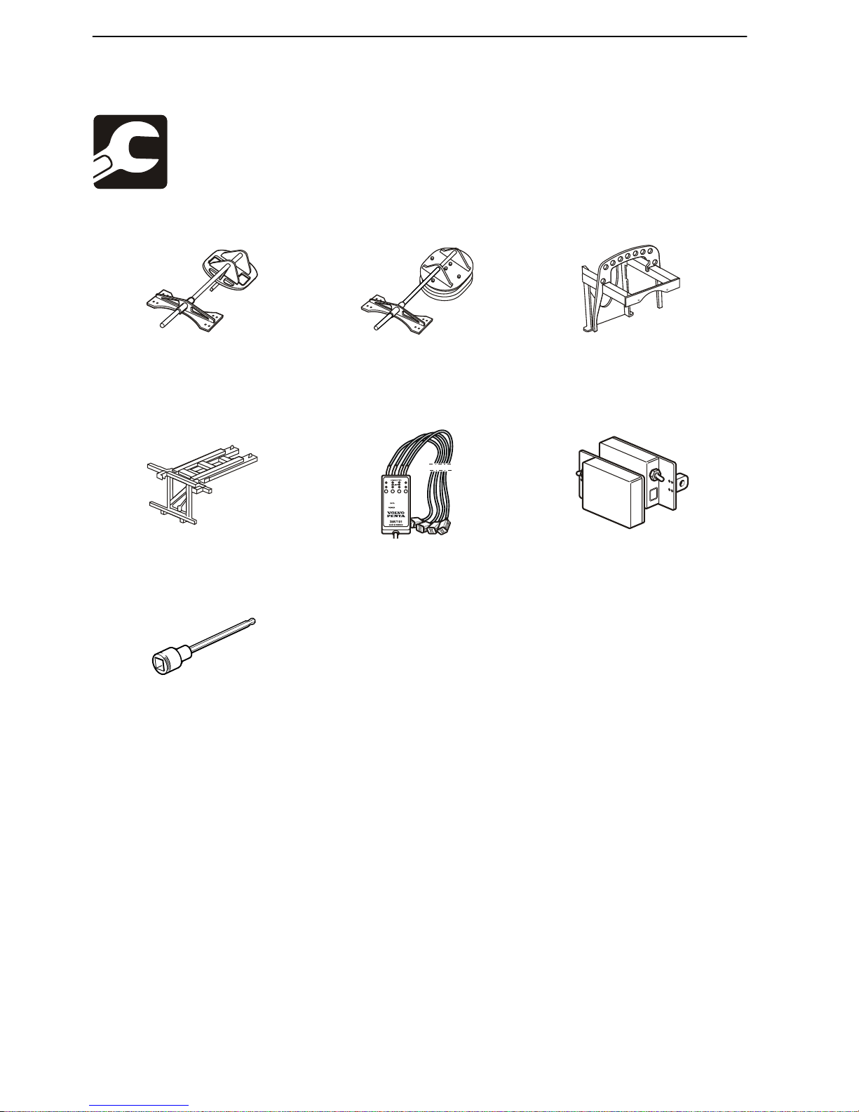
Special Tools
P0010517
P0010518
P0010505
3849633 Drill jig 3594503 Drill jig 21110860 Lifting tool
Location of engine bed and
engine mount positions (hull
inserts)
Lamination of hull inserts and
the location of engine beds
(complete with molding tools).
Attaching device for propulsion
unit when lifting by hoist
P0010506
p0010872
3849664 Lifting tool 3887101 Break-out box 21406897 Calibration tool
Position device when lifting by
fork lift
Used together with the VODIA
tool for calibrating IPS units
Drive unit alignment (complete
pair)
P0001856
3863070 Allen key socket
Torque tightening propeller
retainer rings
Installation Tools and Documentation, Special Tools
10 47704162 10-2014 © AB VOLVO PENTA

Other Special Equipment
p0005125
VODIAVODIA
p0008375
P0004580
88890074 Multimeter 88820047 VODIA, diagnostic
tool
9998493 Hose
Used in combination with
9998339 Manometer
.
PDA only
P0008329
P0004349
21244540 Measuring tool 9998339 Manometer
Measuring engine mount compression
Measuring fuel feed pressure
Installation Tools and Documentation, Special Tools
47704162 10-2014 © AB VOLVO PENTA 11
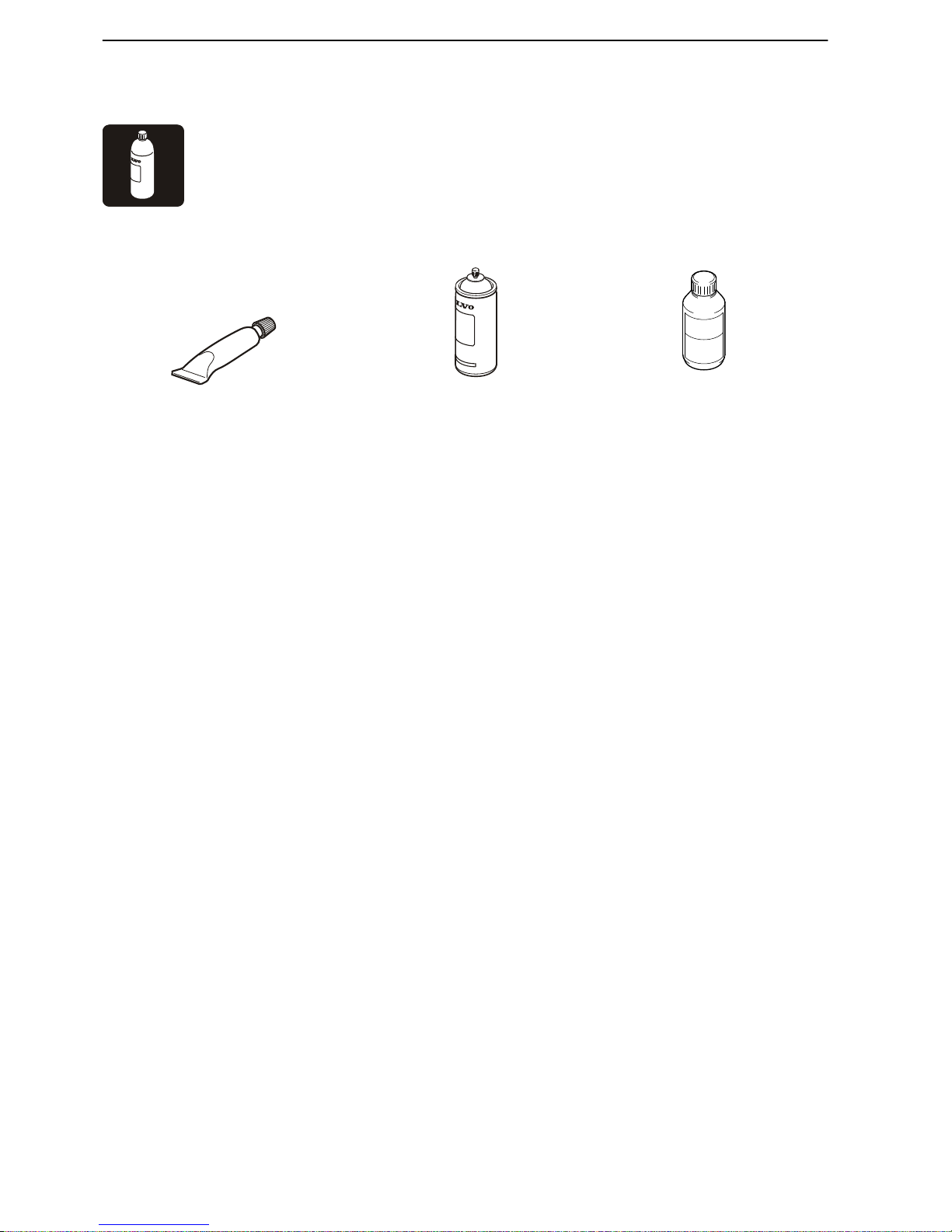
Chemical products
P0001874
P0001871
828250 Grease alt.
21347121 Grease
(400 gr)
1381065 Corrosion protection
3817243 Rubber lubricant
Installation Tools and Documentation, Special Tools
12 47704162 10-2014 © AB VOLVO PENTA

System Information
EVC
Refer to the Installation EVC installation manual for
EVC system installation instructions.
System Information, EVC
47704162 10-2014 © AB VOLVO PENTA 13

Engine Characteristics
Engine Application Ratings
The engines covered by this manual are used chiefly
in
two different operating conditions: Rating 4 and Rat-
ing 5, as described below.
Rating 4
Special light commercial traffic
For light, planing boats in commercial traffic. Operated
for fewer than 800 hours per year.
Typical boats: High-speed patrol boats for search and
rescue and the armed forces, and special high-speed
fishing boats. Recommended cruising speed: 25
knots.
Full power may be utilized for max 1 hour per 12 hour
period. Between full-throttle periods, engine revolutions must be reduced by at least 10% from full rpm.
Rating 5
Recreational use
Only for pleasure boats operated by owners for their
recreation. Operated for fewer than 300 hours per
year.
Full power may be utilized for max 1 hour per 12 hour
period.
Between full-throttle periods, engine revolutions must
be reduced by at least 10% from full rpm.
Engine Characteristics, Engine Application Ratings
14 47704162 10-2014 © AB VOLVO PENTA
Engine Performance
Marine engine power is specified, just like automobile
and truck engines, according to one or more power
norms. Power is specified in kW or hp, always at a
rated rpm.
Most engines provide the power specified on the condition that they have been tested in the conditions the
power
norms state, and have been broken in properly.
According to ISO standards, tolerances are normally
±5 %, which is a reality that must be accepted for series-produced engines.
Power measurement
Engine manufacturers normally measure engine
power at the flywheel, but before power reaches the
propeller, losses occur in the drive train and propeller
shaft bearings. These losses amount to 4–6 %.
All major marine engine manufacturers determine
engine power according to ISO 8665 (supplement to
ISO 3046 for pleasure boats). If an exhaust system is
not included, engine tests are performed with a back
pressure of 10 kPa (1.45 psi).
Engine performance
Engine power is affected by a number of different factors. Among the most important are air pressure, outdoor temperature, humidity, fuel calorific value and
exhaust back pressure. Deviations from normal values
affect diesel and gasoline engines in different ways.
Diesel engines use large amounts of air for combustion. If the mass of air is reduced, the first sign is an
increase in black exhaust smoke. The effects of this
are especially noticeable at the planing threshold when
the engine must produce maximum torque.
If the deviation differs significantly from normal air flow,
the diesel engine will lose power. In the worst case the
loss may be so great that torque is insufficient for the
boat to overcome the planing threshold.
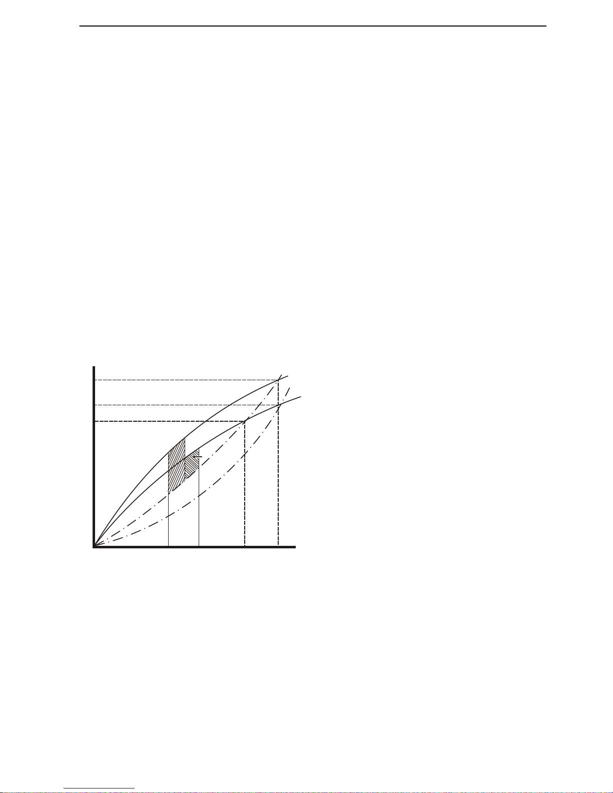
Point A is where the indicated engine power is equal
to the power acting on the propeller. Volvo Penta IPS
drive units have defined propeller sizes that are dimensioned for engine characteristics.
1
2
3
4
5
6
A
B
C
P0004571
Connection between performance-influencing factors in inboard
engines
1
Power
2 rpm
3 Power loss due to atmospheric conditions
4 Loss due to large propeller
5 Critical area
6 Indicated rpm
Engine Characteristics, Engine Performance
47704162 10-2014 © AB VOLVO PENTA 15

Other factors that influence performance
It is important to keep exhaust back pressure low.
Power losses caused by back pressure are directly
proportional to the increase in back pressure, which
also increases exhaust temperature.
Boat
weight is another important factor that influences
speed. Increased boat weight has a great influence on
speed, especially on planing or semi-planing hulls. A
new boat that is tested with half full fuel and water tanks
and without a load, may lose 2-3 knots when it is driven
fully loaded with fuel, water and equipment for the voyage.
Boats made from fiberglass reinforced plastic absorb
water when they are afloat which means they become
heavier over time. Marine fouling is an often-overlooked problem that greatly affects boat performance.
Engine Characteristics, Engine Performance
16 47704162 10-2014 © AB VOLVO PENTA
Arrangement and Planning
Engine Placement
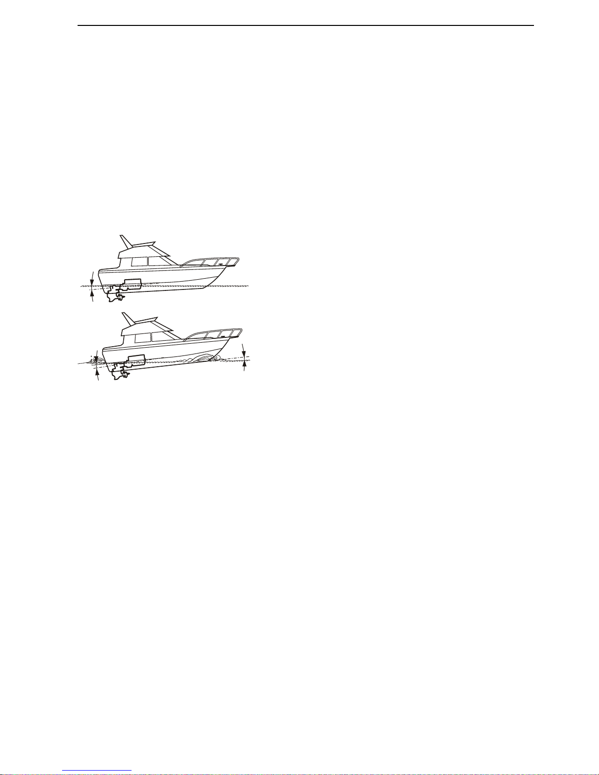
Engine Inclination
To ensure the engine receives lubrication and cooling
in a satisfactory manner, it is important that maximum
engine inclination is not exceeded. Engine inclination
must therefore be checked.
Be
careful to avoid the front of the engine's being lower
than the flywheel, i.e. an exaggerated negative inclination that may impair engine lubrication and cooling
system venting.
Each engine type has a maximum permissible engine
inclination while the boat is under way. This inclination
includes both the installation angle and the increase in
trim angle the boat attains when moving at speed
through the water.
A Engine inclination with the boat at rest.
B Boat trim angle under way.
C Total engine inclination under way, maximum per-
missible inclination (A+B).
A boat's weight distribution is affected by the choice of
driveshaft length.
See technical data for limit values.
P0010566
A
B
C
Arrangement and Planning, Engine Placement
47704162 10-2014 © AB VOLVO PENTA 17
Weight Distribution
The location of the longitudinal center of gravity is of
great
importance for trim angle at top speed etc. Generally speaking, a fast boat should have its center of
gravity further aft than a slower boat.
The center of gravity has great influence on a boat's
static and dynamic stability. It is therefore important to
consider CoG position both when the boat is loaded
and unloaded.
It is important that heavy components such as engines,
fuel and water tanks and batteries be located such that
the best possible trim is achieved when the boat is in
the water, and generally that as low a vertical CoG as
possible is attained.
Fuel and water tanks must be located longitudinally as
close to the center of gravity as possible in order that
the center of gravity is not moved when water and fuel
levels change.
It is an advantage not to locate the fuel tanks in the
vicinity of the hot engine compartment. If possible, the
batteries must be located in a separate, well-ventilated
section.
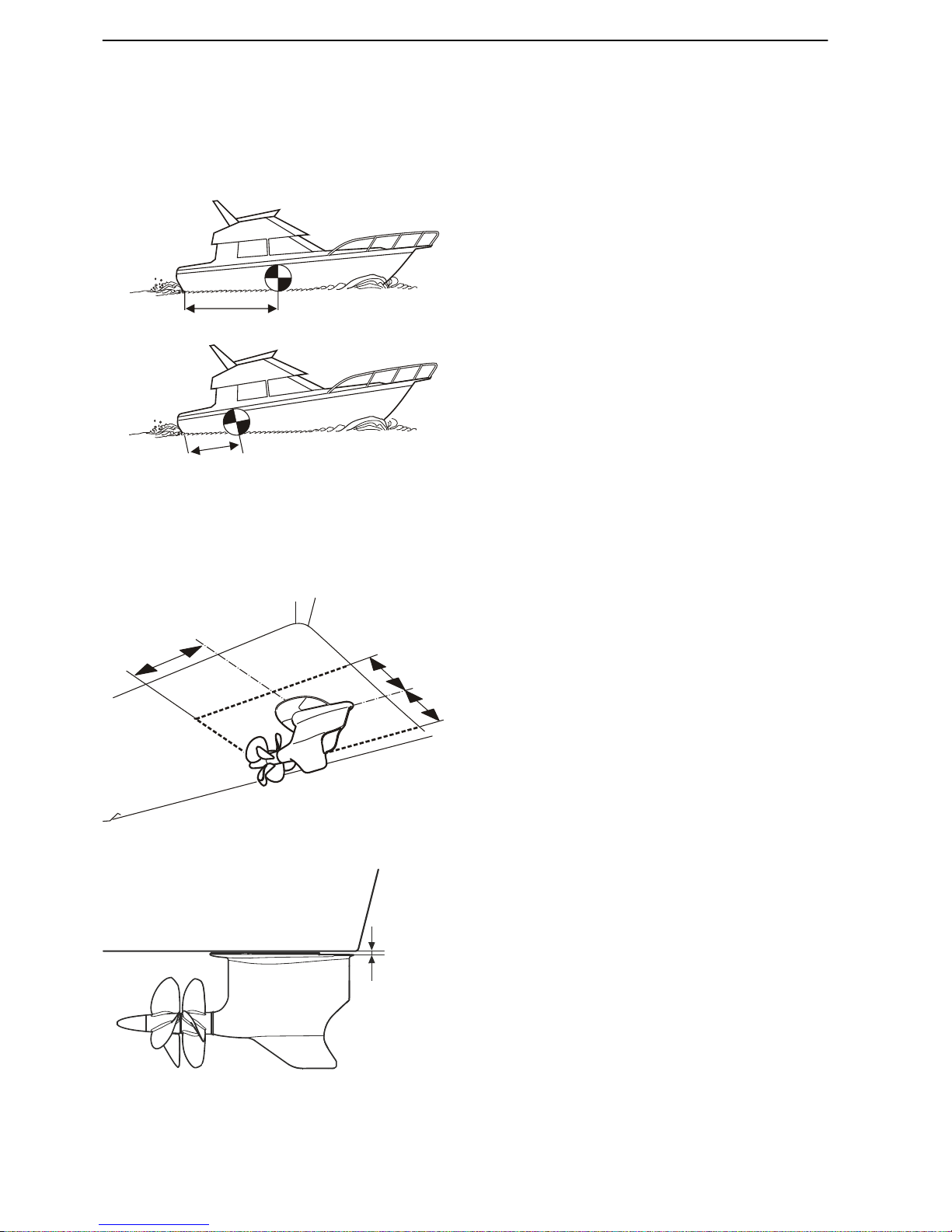
Clearance Around Propulsion Units
Objects that protrude from the hull bottom cause turbulence. If such are present in the vicinity of the drive
units, propeller propulsion ability will be impaired.
Place no objects inside the dashed lines.
A min. 3000 mm (118")
B min. 400 mm (16")
C min. 50 mm (2")
Clearance between hull and Ips drive unit is 9 mm
(+ 5 mm - 2 mm)
A
B
P0005314
Figure A
shows an installation with good weight distribution and trim
angle.
Figure B shows an incorrect installation with poor trim angle as the
result.
A
B
B
P0006153
P0019672
C
Arrangement and Planning, Engine Placement
18 47704162 10-2014 © AB VOLVO PENTA
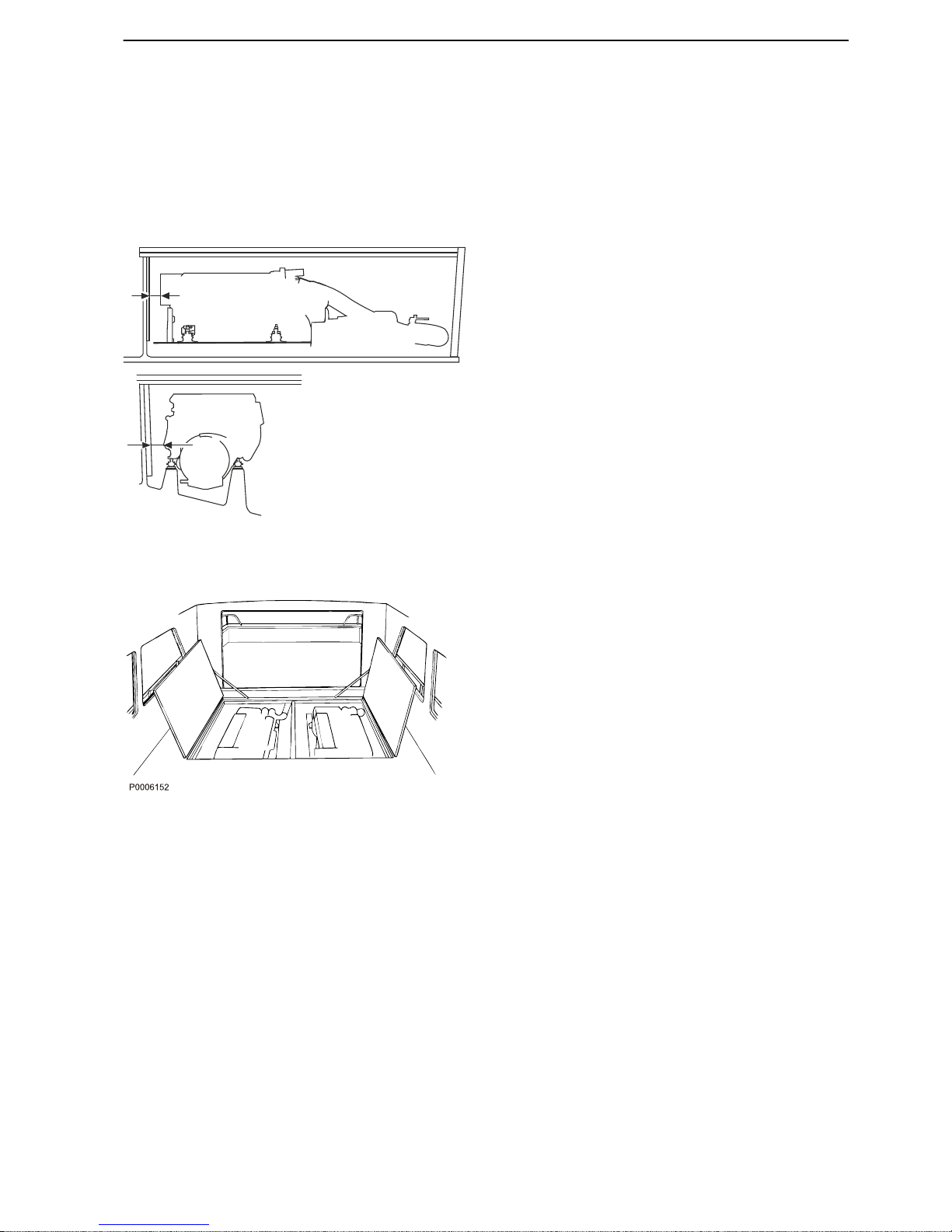
Engine Room
Accessibility for Maintenance
When the engine installation is designed, great
emphasis must be placed on engine service accessibility.
Also make sure that the complete engine can be
lifted out without damage to the boat.
NOTICE! There must also be sufficient space for
sound-dampening materials. The recommended minimum distance for sound-dampening materials is 180
mm (7") (A) and 200 mm (8") (B); see illustration.
Removal of complete engine assembly
If the complete engine assembly must be lifted out of
the boat it is the boatbuilder's responsibility to do so
using reasonable methods for removal and re-installation. This means: within reasonable time using normal resources and methods available to the industry
to limit costs and operational downtime. It is Volvo
Penta policy to avoid installations that involve extra
costs for boat owners during the lifetime of the boat.
A
B
P 1162600
Arrangement and Planning, Engine Room
47704162 10-2014 © AB VOLVO PENTA 19
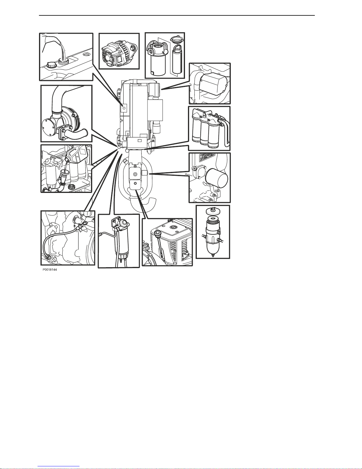
General maintenance
Items that usually require maintenance accessibility:
•
Coolant
• Oil change and filling (engine, drive)
• Filter changes (oil, fuel, air and crankcase
breather)
• Drivebelt change and adjustment/tensioning
• Removal of valve cover
• Changing impeller, seawater pump
• Water filter, cleaning
Repairs
Items that may require maintenance accessibility:
• Removal of injectors, cylinder head, radiator etc.
• Removal or exchange of electrical components
• Removal of flywheel and vibration damper
• Measurement at diagnostic points
Arrangement and Planning, Engine Room
20 47704162 10-2014 © AB VOLVO PENTA
Engine Room Ventilation
Engine performance
Diesel
engines require a surplus of air. Deviations from
normal values first present themselves as more black
smoke than usual. This may be especially noticeable
at the planing threshold when the engine must deliver
the highest possible torque.
If deviations from normal values are great, the diesel
engine will lose power. The power loss may be so great
that a planing boat is unable to overcome the planing
threshold.
In order for the engine to function properly and provide
full power, it is absolutely essential that both inlet and
outlet air ducts are dimensioned and installed correctly.
Two principle conditions must be met:
A The engine must receive sufficient air (oxygen) for
fuel combustion.
B The engine compartment must be ventilated such
that the temperature can be kept at an acceptably
low level.
Ventilation is also important to keep the temperature
of engine electrical and fuel systems low, and to guarantee normal engine cooling.
Ventilation must also be suitably adapted if crew members will be present in the engine compartment.
NOTICE! Current national safety regulations and legislation must be followed. Each classification society
has its own rules that must be followed as required.
Engine power at high altitudes above sea level
In most cases marine engines are used at, or close to,
sea level. However, there are lakes at high altitudes
above sea level.
Operations at high altitudes involve a power loss owing
to a drop in air density (and thereby oxygen levels) as
altitude increases. This will result in the development
of smoke and the turbocharger running at abnormally
high rpm with increased wear.
However, power loss is not significant below approx.
500 m (1640 ft) above sea level. At altitudes in excess
of 500 m (1640 ft) above sea level, power loss is
around 0.1% per 100 m (328 ft).
Volvo Penta IPS 650, 800 and 950 engines are not
suitable for operations above 1,500 m (5,000 ft).
Arrangement and Planning, Engine Room
47704162 10-2014 © AB VOLVO PENTA 21

Dimensioning of air intake and ducts
The following basic facts must be considered in
calculations when planning an installation.
•
All combustion engines, regardless of manufacture
or type, require a certain amount of oxygen (or air)
for the combustion process. However, diesel
engines work with a somewhat larger air surplus
than gasoline engines.
•
Furthermore, all engines emit a certain amount of
heat to the surroundings, i.e. engine compartment.
•
Heat radiation is smaller on modern, compact
engines
than on older, less compact engines. Mod-
ern engines enjoy a great advantage in this.
Ducts and pipes for inlet and outlet air
It is an advantage if ducts and pipes for inlet and outlet
air can be planned as early as the design stage, as they
can then be built into the hull or superstructure. This
eliminates the requirement for separate ducts.
It is relatively simple to design a system for providing
the engine with a sufficient quantity of combustion air,
but significantly more difficult to ventilate heat radiation
away.
The engine draws in air efficiently and naturally takes
it from whatever direction it can. If inlet and outlet ducts
are too small, the engine will draw in air from both ducts
and no ventilation air will be expelled through the outlet
duct. This will create dangerously high temperatures in
the engine compartment.
Most of the engine heat radiation must be carried away
from the engine compartment. It is a mandatory
requirement to keep engine compartment temperature
below the maximum permissible limit.
Fans
Normally an extraction (suction) fan must be installed
in the outlet duct to ventilate the engine compartment
more efficiently and thus keep engine compartment
temperature low.
Conversely, fans may never be installed in the inlet
duct as this may lead to engine compartment overpressure, with the risk of gases or air leaking into other
parts of the boat.
For diesel engines the fan may very well be thermostat
controlled; it must start at an engine compartment temperature of around +60 °C (+140 °F), measured in the
engine compartment.
NOTICE! Fan hose connections for diesel engines
must be located as high in the engine compartment as
possible to carry away hot air, while for gasoline
engines as low as possible to carry away fumes.
Arrangement and Planning, Engine Room
22 47704162 10-2014 © AB VOLVO PENTA

Engine temperature
It
is important that inlet temperature be kept as low as
possible bearing in mind that engine performance figures apply at a test temperature of +25 °C (+77 °F).
Temperature
≤ 25 °C (77 °F) Full power
> 25 °C (77 °F) Power loss approx. 1% per 10
°C
Inlet air temperature at the air filter may not be higher
than 25
°C (77 °F) for full power to be achieved. During
sea trials the temperature in the air filter must not be
higher than 20 °C (68 °F) above the outside temperature.
Engine surface temperature is rather high at certain
points. Certain individual engine components such as
charge regulators and relays must therefore be installed on bulkheads or at other locations where the temperature is relatively low.
Maximum temperature at electrical component
installation locations is 70 °C (158 °F). However, the
starter motor and alternator have their given locations.
Engine compartment pressure
Volvo Penta recommends that negative pressure in the
engine compartment not fall below 0.5 kPa (0.07 psi)
at full speed. A slight negative pressure in the engine
compartment is not harmful and it prevents gases from
being forced out of the engine compartment into other
boat spaces.
Arrangement and Planning, Engine Room
47704162 10-2014 © AB VOLVO PENTA 23

Engine air consumption
The engine consumes a certain amount of air during
the
combustion process. This requires the inlet duct to
have a certain internal cross-sectional area.
This area can be calculated using the formula:
A = 1.9 × engine power
A = Area in cm
2
Engine power in kW
The value applies to inlets, without obstacles, that are
up to 1 m (3.3 ft) with only one 90-degree bend. The
bend radius must be at least twice the duct diameter.
If longer ducts or more bends are used, the area must
be corrected by multiplying by the coefficient in the
Coefficient of bends table.
Coefficient of bends
Duct length, m (ft.)
Number
bends
1 (3.3) 2 (6.6) 3 (9.8) 4 (13.1) 5 (16.4)
1 1 1.04 1.09 1.13 1.20
2 1.39 1.41 1.43 1.45 1.49
3 – 1.70 1.72 1.74 1.78
Engine compartment ventilation
In addition to its air consumption, the engine radiates
heat. Heat radiation must be carried away from the
engine compartment in order to keep the temperature
down to permissible values.
The same dimensions must be chosen for the outlet
and
inlet channels in order to achieve low flow speeds
and low noise levels.
Ventilation inlet/outlet area is calculated according
to the following formula:
Area (cm2) = 1.65 × engine power (kW)
These values must be corrected in accordance with the
Coefficient of bends table in regard to bends and duct
length.
Outdoor temperature is assumed to be +30 °C (86 °F).
Correction factors according to the Correction factor
table must be used where applicable.
Correction factor
Outside temperature °C
(°F)
Correction factor
+20 (68) 0.7
+30 (86) 1.0
+40 (104) 1.4
Arrangement and Planning, Engine Room
24 47704162 10-2014 © AB VOLVO PENTA

Choice of fan
The fan must be dimensioned for airflow according to
the following:
Outlet air (m3/min) = 0.07 × engine power (kW)
The
total pressure increase at the fan must be 10 mm
(0.39") water gauge (100 Pa).
These two values, flow and total pressure increase, are
sufficient for selecting a fan. If the fan is installed
directly on the bulkhead, i.e. without a connecting duct,
the total pressure increase value may be reduced by 7
mm (0.28") water gauge (70 Pa). This means that a
somewhat smaller fan may be used.
Arrangement and Planning, Engine Room
47704162 10-2014 © AB VOLVO PENTA 25

Calculation of air ducts
Example 1: IPS650, 375kW (510 hp)
Calculation of areas for one 375kW engine with an
unlimited
airflow and an outside temperature of +30 °C
(+86°F).
Air consumption:
The following is obtained for each engine:
Area for engine air consumption: 1.9 × 375 = 713
cm2 (110.5 sq.in)
No corrections according to the Coefficient of bends
and Correction factor tables The area 713 cm² (110.5
sq.in) gives a duct diameter of 267 mm (10.5") for each
engine (2√(area/π).
Multiply by the number of engines to calculate the area
of the engine compartment inlet duct.
Ventilation:
1
Air intake: Area = 1.65 × 375 = 619 cm2 (95.4
sq.in). This gives a diameter of 304 mm (12.0") for
a single engine.
2
Air outlet: Area = 1.65 × 375 = 619 cm2 (95.4
sq.in). This gives a diameter of 304 mm (12.0") for
a single engine.
3 Extraction fan capacities: 0.07 × 375 = 26.2
m3/min (1091 ft3/min).
4 Multiply each sum by the number of engines to cal-
culate the area and fan capacity for a common
engine compartment.
Arrangement and Planning, Engine Room
26 47704162 10-2014 © AB VOLVO PENTA

Calculation of air ducts
Example 2: IPS800, 459 kW (625 hp)
Calculation of areas for one 459 kW engine with an
unlimited
airflow and an outside temperature of +30 °C
(+86°F).
Air consumption:
The following is obtained for each engine:
Area for engine air consumption: 1.9 × 459 = 872
cm2 (135.5 sq.in)
No corrections according to the Coefficient of bends
and Correction factor tables The area 874 cm² (135.5
sq.in) gives a duct diameter of 267 mm (10.5") for each
engine (2√(area/π)).
Multiply by the number of engines to calculate the area
of the engine compartment inlet duct.
Ventilation:
1
Air intake: Area = 1.65 × 459 = 757 cm2 (117.6
sq.in). This gives a diameter of 304 mm (12.0") for
a single engine.
2
Air outlet: Area = 1.65 × 459 = 757 cm2 (117.6
sq.in). This gives a diameter of 304 mm (12.0") for
a single engine.
3 Extraction fan capacities: 0.07 × 459 = 32.1
m3/min (1091 ft3/min).
4 Multiply each sum by the number of engines to cal-
culate the area and fan capacity for a common
engine compartment.
Arrangement and Planning, Engine Room
47704162 10-2014 © AB VOLVO PENTA 27

Calculation of air ducts
Example 3: IPS950, 533 kW (725 hp)
Area
calculations for one engine with a 2 m (6.6 ft) long
duct, 2 bends and an outside temperature of +20 °C
(+68 °F).
Air consumption:
Area for engine air consumption: 1.9 × 533 = 1012.7
cm2 (156.9 sq.in)
Correction for duct length and bends = 1.41 from the
Coefficient of bends table.
This gives 1012.7 × 1.41 = 1428 cm2 (221.3 sq.in). The
area 1428 cm2 (213.9 sq.in) corresponds to a duct
diameter of 419 mm (16.5").
Multiply by the number of engines to calculate the area
of the engine compartment inlet duct.
Ventilation:
1 Inlet, engine compartment: Area = 1.65 × 533 =
880 cm2 (136.4 sq.in). This corresponds to a duct
diameter of 329 mm (13").
2 Outlet, engine compartment: Area = 1.65 × 533
= 880 cm2 (136.4 sq.in). This corresponds to a duct
diameter of 329 mm (13").
3 Correction, inlet and outlet: Air temperature = 0.7
from the Correction factor table, plus a correction
for duct length and bends = 1.41 from th Coefficient
of bends table.
This gives 880 × 0.7 × 1.41 = 868.6 cm2 (134.6
sq.in). This corresponds to a duct diameter of 327
mm (12.9") for each inlet and outlet.
4 Extraction fan capacities: 0.07 × 533 (kW) = 36
m3/min (1271 ft3/min).
5 Multiply each sum by the number of engines to cal-
culate the area and fan capacity for a common
engine compartment.
Arrangement and Planning, Engine Room
28 47704162 10-2014 © AB VOLVO PENTA

Location of ventilators and air inlets
NOTICE! Air inlets and outlets may never be located
on the transom. Air in this area mixes with water and
exhaust fumes, and must never be allowed into the
boat.
Air inlet function
Air inlets and outlets must function well even in bad
weather
and must therefore have efficient water traps.
For the most part noise insulation must be built in.
Air inlets and outlets must be located as far away from
each other as possible so that an effective through flow
is achieved.
If inlets and outlets are too close to each other air is
able to recirculate, which will provide inadequate ventilation.
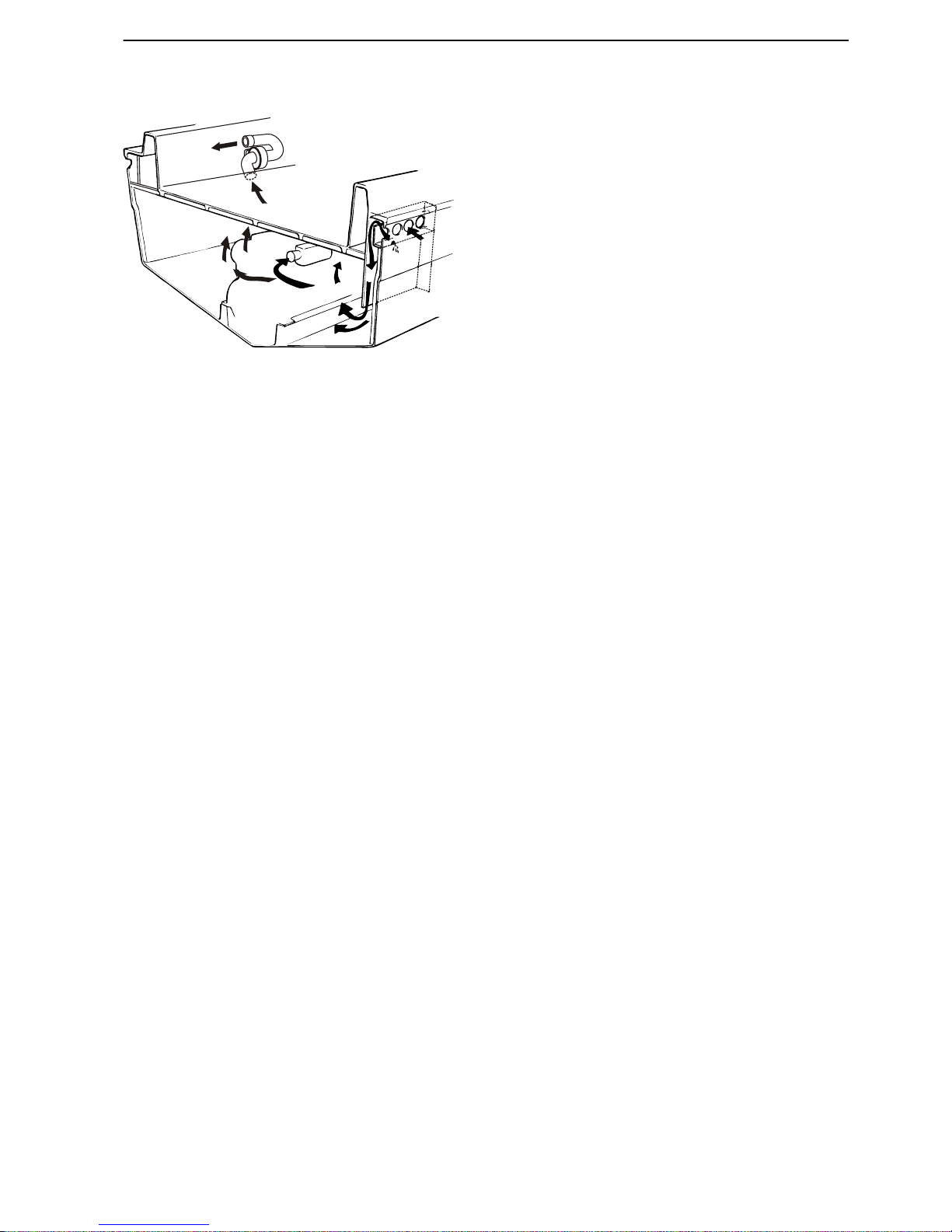
Location of air ducts
Ducts or pipes for engine air supply must be run to a
place as close to the air filter as possible, but with a
minimum distance of 20–30 cm (8–12") in order to definitely prevent water from entering the engine; refer to
the adjacent figure.
The inlet ventilation duct for diesel engines must be led
in far down into the engine compartment, but not so far
down that any bilge water is able to block air supply.
The outlet duct must be located diametrically opposite
on the other side of the engine.
All ducts and pipes must be run such that there is the
least possible flow resistance. Bends may not be
sharp, but must be moderately rounded. The minimum
radius is double the diameter. Obstacles or constric-
tions must always be avoided.
The ducts must be cut obliquely at the ends to provide
best flow.
Always take any llocal regulations into consideration.
If it is not possible to arrange drainage, ventilation
hoses must be bent upwards somewhat in order to
form a gooseneck that prevents seawater forcing its
way into the engine compartment. Remember to build
the engine compartment as spaciously as possible to
facilitate engine service.
1
2
3
4
5
P0004733
1 Engine air filter
2
Inlet duct, engine compartment
3 Outlet
4 Water trap
5 Extraction fan
P0004734
Arrangement and Planning, Engine Room
47704162 10-2014 © AB VOLVO PENTA 29

Sound Absorption
The
drive assembly must be installed so that noise and
vibrations are minimized. The noise that occurs is party
airborne noise and partly structural noise (vibrations).
Structural noise
Engine vibrations are transferred to the hull via the
engine mounts and engine bed. Other transfer routes
are through the transmission and propeller system,
exhaust pipes, coolant pipes, fuel pipes and electrical
and control cables.
Propeller pressure waves are transmitted through the
water to the hull. Propeller drive pulses are transferred
to the hull via support brackets, bearings and seals.
Airborne noise
This section concerns airborne noise from the engine
compartment. The most important method of reducing
airborne noise from the engine compartment is to seal
it properly. Further noise reductions can be achieved
by laying sound insulation material and by designing
noise baffles in the air inlets.
The engine installation must be noise insulated to provide as low a noise level as possible. Build noise baffles into the engine compartment. There are different
types of noise baffles to choose from. The illustration
shows a type that also provides drainage.
It is important to ensure that the insulation material is
sufficiently thick.
The greatest possible care must be taken to screen the
noise source as much as possible. Screen off the entire
bulkhead down to the hull, but leave a little gap so that
bilge water does not force its way into the insulation
material.
Cracks and openings etc. must be carefully sealed with
insulation material. In cases where the engine is installed beneath the deck, all bulkheads and decks must be
insulated.
1
P0004735
Engine compartment noise baffles
Arrangement and Planning, Sound Absorption
30 47704162 10-2014 © AB VOLVO PENTA

Make sure that there is sufficient space for inspections,
service and repairs and for engine movement during
operations before the insulation material is installed.
Also make sure that all covers are properly insulated.
Examples of insulation material design are shown
below. This type of insulation material is glued to the
frame.
1
2
3
P0004739
Insulation material installed on wood (plywood):
1 Wood (plywood)
2 Flameproof absorbent layer
3 Flameproof, reflective and noise insulating foil
1
2
3
4
P0004740
Insulation material installed on GRP:
1
GRP
2 Iron/PVC, thickness 2.5 mm (0.1”)
3 Flameproof absorbent layer
4 Flameproof, reflective and noise insulating foil
NOTICE! The insulation materials look different
depending
on the material the frame is made of - GRP
or wood.
P0006333
Arrangement and Planning, Sound Absorption
47704162 10-2014 © AB VOLVO PENTA 31

When electrical cables are run through a bulkhead, it
is advantageous to run them through a conduit or
grommet that can be sealed properly. This also protects the cable against wear.
Fuel hoses that are run through bulkheads must be
protected by grommets. The grommet seals and protects the hose against sharp edges that may cause
leaks.
Other lines such as electrical and battery cables can
be run through a rubber hose or a special PVC pipe
(installation pipe) built into the hull. Any gaps between
the pipes and the cables can be sealed with insulating
material or sealing compound.
P0004741
Bulkhead bushings
P0006334
Fuel hose protected by a grommet
Arrangement and Planning, Sound Absorption
32 47704162 10-2014 © AB VOLVO PENTA

Electrochemical Corrosion
General
NOTICE! Refer to the Service handbook Corrosion
measurement,
DPH/DPR & IPS for further information.
Corrosion theory
Corrosion in water is always electrochemical in nature.
This means that a weak electric current occurs at the
same time as chemical reactions takes place. Two
chemical reactions are required to make a metal corrode, an oxidation reaction (metal dissolving) and a
reduction reaction (generally oxygen consuming). Oxidation is referred to as an anode reaction and reduction is referred to as a cathodic reaction. In an oxidation
reaction, electrons are freed which are transported in
the metal to another point, where they are consumed
in a cathodic reaction.
Electrons are thus transported in the metal from the
anode to the cathode. This causes a weak DC current
in the opposite direction. An electric circuit must be
closed. This is achieved by the transport of ions in the
water.
Anodic and cathodic reactions must always balance
each other, which means that the electrons released
at the anode must be consumed at the cathode. If the
anodic and cathodic reactions occur evenly distributed
across the entire surface, general corrosion occurs.
The depth of attack then becomes basically equal
across the entire surface. This commonly occurs on
steel and bronze.
Fe Fe2+ +2 e-
O2 + H2O + 2 e 2 OH-
ANODE
CATHODE
P0011416
I
P0011417
Arrangement and Planning, Electrochemical Corrosion
47704162 10-2014 © AB VOLVO PENTA 33

If the anodic and cathodic reactions occur at different
points,
local corrosion occurs, i.e. deeper attack at certain points. The attacks on materials which can be passivated, such as stainless steel and aluminum are generally localized. There are different types of local corrosion. The most common types of attack on stainless
steels and aluminum are pitting corrosion and crevice
corrosion.
In addition to these local attacks, attack can be caused
by galvanic corrosion or stray currents. In areas where
rapid water flow occurs, damage cause by cavitation
can also occur.
If we ignore attacks related to material defects, the following types of corrosion can occur:
- General corrosion.
- Pitting.
- Crevice corrosion.
- Galvanic corrosion.
- Stray current corrosion.
- Cavitation.
A brief description of each type of corrosion is given
below.
General corrosion
General corrosion is the most common type of corrosion. This results in even attack across all or large parts
of the surface.
In seawater, mild steel and bronze are subject to general corrosion, but not stainless steel. In stationary
seawater, the corrosion rate of mild steel is about 0.1
mm/year (0.3 mm/year at the waterline) unless the
steel is protected by cathodic protection. Bronze is initially attacked at a rate of 0.05 mm/year, but after some
time the corrosion rate falls to a low level, since the
corrosion products (black, brown) have a protective
effect. Green/blue corrosion products are a sign of
higher corrosion rates and that the protective layer has
not been developed.
Aluminum can be subject to a certain amount of general corrosion in rapidly flowing water, but not in stationary water.
p0011418
Arrangement and Planning, Electrochemical Corrosion
34 47704162 10-2014 © AB VOLVO PENTA

Pitting corrosion
Pitting corrosion can occur on stainless steel and aluminum. The attack is caused by localized breakdown
of the passive oxide film on the metal surface. In natural water, it is generally chloride ions that initiate the
attack. The risk increases with rising water temperatures. There is a number of aluminum alloys with very
good
resistance to corrosion by seawater. If these are
connected together with more noble metals, they will
be attacked due to galvanic corrosion, however.
Very high levels of chromium and molybdenum are
required, above all, to make stainless steel fully resistant to the risk of pitting corrosion. If there is weak
cathodic protection (sacrificial anodes), excellent protection against pitting corrosion can be obtained on
simpler steels. Alloys of lower grades than 316 should
be avoided, however.
Crevice corrosion
An attack in the gap between two metal surfaces, or
between one metal surface and another materials is
called crevice corrosion. A so-called oxygen depletion
cell is formed when oxygen transport into the crevice
is lower than oxygen transport out to the cell opening.
Separate anodic and cathodic surfaces are formed.
The cathodic process, which requires access to oxygen, is formed in the gap opening and the anodic process, metal dissolving, takes place inside the gap. Crevice corrosion can occur on most metals, but the risk is
greatest on metals that can be passivated, such as
aluminum and stainless steel.
Deposit corrosion is closely related to crevice corrosion. It takes place under deposits and marine fouling
such as barnacles.
p0011419
p0011420
Arrangement and Planning, Electrochemical Corrosion
47704162 10-2014 © AB VOLVO PENTA 35

Galvanic corrosion
Metals From To
Galvanic corrosion is probably the most common
type of corrosion. It occurs when two metals of different nobility are in electric contact and are submerged
in the same body of water at the same time.
The least noble metal is corroded.
Information about the nobility of different metals is
obtained from galvanic potential tables which have
been prepared in various fluids, such as seawater.
See table to the left:
There are four factors which influence the seriousness of galvanic corrosion in each individual case.
These are:
- Area relationship between the anode (less
noble metal) and the cathode (more noble
metal). If the anode is small in relation to the
cathode, the depth of attack will be greater than
if the situation was reversed.
- Conductivity of the water. Seawater conducts
electricity better than fresh water, and corrosion
takes place at a greater rate.
- Potential difference between the two metals. A
large potential difference increases the power
behind the process.
- Lower corrosion rate can be obtained if the
more noble metal can be passivated. This
means that stainless steel is more noble than
copper, but the galvanic corrosion will be more
severe on aluminum when connected to copper
than when connected to stainless steel.
In seawater, total galvanic corrosion counted in
grammes of metal, will be greater than in water which
is not so salt. The greatest depth of corrosion on a
metal can be equally large in brackish or fresh water.
The better conductivity of seawater means that the
attack will be distributed evenly across the entire surface. In fresh water, there will be more local attack
close to the point of contact.
Graphite +0,19 +0.25V
Stainless steel 18‑8, Mo,
in passive state *
±0,00 -0.10 V
Stainless steel 18‑8 in
passive state *
‑0,05 -0.10 V
Nickel ‑0,10 -0.20 V
Nickel-aluminum-bronze -0,13 -0.22 V
Lead ‑0,19 -0.25 V
Silicon bronze (Cu, Zn, Si,
Mn, Sn)
‑0,26 -0.29 V
Manganese bronze (Cu,
Zn, Si, Mn, Sn)
‑0,27 -0.34 V
Aluminum brass (Cu, Zn,
Al)
‑0,28 -0.36 V
Solder (Pb, Sn) ‑0,28 -0.37 V
Copper ‑0,30 -0.57 V
Tin ‑0,31 -0.33 V
Red brass (Cu, Zn) ‑0,30 -0.40 V
Yellow brass (Cu, Zn) ‑0,30 -0.40 V
Aluminum bronze ‑0,31 -0.42 V
Stainless steel 18‑8, Mo,
in active state **
‑0,43 -0.54 V
Stainless steel 18‑8 in
active state **
‑0,46 -0.58 V
Cast iron ‑0,60 -0.71 V
Steel ‑0,60 -0.71 V
Aluminum alloy ‑0,76 -1.00 V
Galvanized iron and steel ‑0,98 -1.03 V
Zinc ‑0,98 -1.03 V
Magnesium and magne-
sium alloy consumed
‑1,60 -1.63 V
* Metals are in a passive state when they have a thin,
corrosion inhibiting coating. This coating is not
present in the active state.
** Still water.
Arrangement and Planning, Electrochemical Corrosion
36 47704162 10-2014 © AB VOLVO PENTA

cathode
anode
anode
cathode
1
2
P0011421
1 Seawater
2
Fresh water
The following should be considered, to counteract
galvanic corrosion:
-
Do not connect metals which are far away from
each other in the galvanic potential table.
- Insulate different metals from each other by
using plastic or rubber (must not contain graphite).
- Paint the structure. The surface of both metals
should be painted. If painting is restricted to only
the less noble metal, heavy galvanic corrosion
could occur on surfaces where there is paint
damage. The reason for this is that the cathode/
anode relationship will be unfavorable.
- Install cathodic protection.
Stray current corrosion
As we learned in the corrosion theory chapter, corrosion occurs when a DC current flows into the water
from a metal surface. Similar stray currents from the
drive
can occur if there is a fault in the boat’s electrical
system, such as if couplings are exposed to dirt and
moisture, components are incorrectly installed or damaged. Stray currents can come from shore current
installations or adjacent boats. All metals, except a few
noble metals, are corroded by stray currents. Corrosion rates can be very high.
The sacrificial anodes on the drive are not dimensioned to counteract any stray currents. If stray currents occur, the anodes will be consumed very quickly
and the drive will be attacked.
Aluminum is particularly vulnerable to stray currents. If
the current density on the surface is high, corrosion can
also occur when there is a stray inwards current. AC
currents can also cause damage. The AC corrosion
rate for aluminum is 30% of the rate for DC. The corresponding rates for steel, copper and zinc are much
lower, at 1 %. Please refer to the figure to the left.
1200
1000
800
600
400
200
0
AL DC
AL AC
CU DC
CU AC
FE DC
FE AC
cm3/Ampere
P0011422
Arrangement and Planning, Electrochemical Corrosion
47704162 10-2014 © AB VOLVO PENTA 37

Corrosion protection
Drives are protected from corrosion by a number of
measures.
-
Alloys which are resistant to salt water.
- Avoidance of unsuitable combinations of metals.
Where appropriate, a favorable relationship
between anode and cathode is established.
- High quality surface treatment.
- Cathodic protection.
- Carefully designed electrical system.
- Recommendations to minimize external interference.
Recommendations from Volvo Penta and anti fouling
manufacturers must be followed. In addition, the material must be resistant to the alkali that is formed on
cathodically protected surfaces.
Cathodic protection is arranged by supplying a weak
DC current from an anode to the protected object. The
current which leaks in counteracts the corrosion current. The higher the protection current, the lower is the
rate of corrosion.
The current required for protection can be generated
in two ways. These are either with sacrificial anodes or
by applying a current. If sacrificial anodes are used, the
current is generated by connecting the protected
object with a less noble metal (anode). The difference
in electric potential creates a protective galvanic current. It can be said that corrosion is transferred to the
anode, which is why they are referred to as sacrificial
anodes.
Zn
P0011424
Zn
P0011425
Arrangement and Planning, Electrochemical Corrosion
38 47704162 10-2014 © AB VOLVO PENTA

If a current is applied, this is supplied from an external
source (rectifier, battery).
The materials used in sacrificial anodes are zinc, aluminum,
magnesium and iron. Please note that special
alloys are used, to meet the following requirements:
- No passivation, i.e. they do not stop supplying current.
- Even consumption.
- Low polarization tendency, i.e. they retain a sufficient potential difference to the object.
- Low self-corrosion.
Only use original anodes. Never paint over the anodes.
Iron anodes can be used to protect stainless steel and
bronze objects. Magnesium anodes can be used in
fresh water where the current supplied by zinc anodes
may not be enough in some cases. Please note that
magnesium anodes give overprotection to aluminum
in seawater. There is no risk of overprotection of aluminium if zinc or aluminum anodes are used for protection.
P0011426
Arrangement and Planning, Electrochemical Corrosion
47704162 10-2014 © AB VOLVO PENTA 39

Definitions
Single-pole system
In a single-pole system the actual engine block is
used
as the negative ground return for all components
on the engine block.
Two-pole system
In a two-pole system each electrical component on
the engine has an insulated direct current ground
return. The alternator, starter motor and all sensors/
senders are electrically insulated from the engine
block and are supplied without a braided ground strap
installed between the starter motor and engine block.
The engine block is not connected to the battery negative terminal (-).
All IPS engines are two pole.
Isolation transformer
A transformer with galvanically separated input and
output windings.
The isolation transformer separates galvanic shore
power from the boat and reduces the risk for galvanic
corrosion and stray current corrosion as described in
ABYC circuit diagram 8 and text E-11.7.2.2.1.4 thru
5. Corrosion damage caused by stray currents will not
be compensated for under warranty.
Ground fault circuit interrupter (GFCI)
A health and safety protection device, the GFCI cuts
the current to a circuit when current to ground
exceeds a predetermined value.
Spark generation between live conductors and
ground may occur at relatively low currents and will
not trip circuit breakers. Moreover, very low currents
may also constitute a danger for personnel. A GFCI
must be installed on the other side of the isolation
transformer as ground fault protection in the boat.
GFCI tripping sensitivity and tripping times must meet
local standards.
A GFCI located on the other side of the isolation transformer safeguards ground fault protection in the boat.
This is supplement to ABYC E-11 that ensures a
higher level of protection against electric shock.
Protection against electrochemical
corrosion
In order to avoid galvanic corrosion to underwater
components
such as hull fittings, swim ladders etc., it
is important that they be protected. Volvo Penta recommends connecting all components to a protection
anode (normally made of zinc) installed on the
transom. Trim tabs may have their own protection.
NOTICE! Normally, the system connecting individual
components must not have any contact with the negative circuit in the boat electrical system.
Local recommendations, e.g. ABYC, may state that
the battery negative terminal be connected to the galvanic circuit. If the galvanic circuit is connected to the
battery negative terminal (-), the engine block must
also be connected by a cable of a capacity sufficient
to conduct current at engine start; refer to the description in ABYC chapter E-11.
IMPORTANT!
If there is a risk for galvanic corrosion and stray current corrosion, an isolation transformer must be installed.
Volvo Penta IPS drive units are manufactured in a
nickel aluminum bronze alloy and are protected
against corrosion by two anodes. One is installed in
the exhaust system (iron) and the other on the
transom (aluminum). The drive unit has an underwa-
ter surface area that exceeds 1 m2 (10.8 ft2).
IMPORTANT!
The anodes must not be painted over.
IMPORTANT!
Do not connect Volvo Penta IPS units to each other.
IMPORTANT!
Do not connect the Volvo Penta IPS units to the
engine or any other components on board.
IMPORTANT!
Do not connect any other equipment to the Volvo
Penta IPS transom-mounted anode.
NOTICE! The above recommendations do not conflict
with ABYC E-11, in particular paragraphs 11.18.1 and
11.17.2.3.
IMPORTANT!
In steel and aluminum installations it is important to
ensure good insulation between the Volvo Penta IPS
unit and the hull. Volvo Penta disclaims responsibility
for any hull corrosion.
Arrangement and Planning, Electrochemical Corrosion
40 47704162 10-2014 © AB VOLVO PENTA

Protection against electrostatic
discharges and lightning strikes
For advice regarding the prevention of dangerous situations as a result of electrostatic discharges or lightning, refer to the applicable literature published by
national and international standards organizations
such as the International Electrotechnical Commis-
sion and American Boat and Yacht Council.
Special publications IEC 60092-507:2000 Electrical
installation
in ships Part 507: Pleasure craft, and ABYC
Standards and guidelines H-33 and E-4 may provide
guidance.
Painting a Volvo Penta IPS drive unit
Volvo Penta recommends that drive units be painted
in cases where the boat is used in waters where anode
consumption is higher than acceptable. This will
reduce anode consumption as the bronze surface
exposed to water is reduced significantly by external
painting. In order for the paint to adhere to the drive
unit a suitable base coat is recommended before antifouling paint is applied. Painting drive units is also useful in areas with much marine fouling.
IMPORTANT!
Do not use copper-based paints on the drive unit.
IMPORTANT!
Do not paint the groove (A) between the drive unit and
hull (does not apply to metal boats, where the inside of
the IPS hole is painted with anti-foulding paint).
IMPORTANT!
Do not paint the white plastic part (B).
A
B
P0006329
Arrangement and Planning, Electrochemical Corrosion
47704162 10-2014 © AB VOLVO PENTA 41

Shore supply and alternator installation
Example of an installation with isolation
transformer
For installation, refer to local regulations.
Single phase, 240 VAC system
1 2
3
24
23
22
4
5
6
7
21
20
8
9
10
111213
19
18
17
16
15
14
P0004769
1 Phase
2
Zero
3 Protective ground
4 2-pole, 3-wire grounded contact and female socket
5 Shore side
6 Boatside
7 Transformer shield
8 Alternator circuit breaker
9 Alternator (accessory)
10 To DC negative buss and ground plate, boat
11 Phase
12 Zero
13 Protective ground
14 240 VAC ground, female socket
15 240 V AC apparatus
16 Separate circuit breaker (typical)
17 GFCI
18 Changeover switch, land / alternator
19 Encapsulated single-phase 1:1 isolated transformer with metal shield
20 Main switch, shore power, with overvoltage protection
21 Power supply (isolated electrically from boat)
22 Connector, shore power cable
23 Shore supply cable
24 Shore connection
Arrangement and Planning, Electrochemical Corrosion
42 47704162 10-2014 © AB VOLVO PENTA

Two-phase, 120/240 VAC primary, 120/240 VAC secondary
1
2
3
27
25
4
8
9
10
11
12
13
14
15
16
17
18
7
6
5
P0004770
24
26
23
22
21
20
19
1 Phase
2
Zero
3 Phase
4 Protective ground
5 3-pole, grounded pin-type connector and 4-conductor socket
6 Shore side
7 Boatside
8 Transformer shield
9 Circuit breaker, alternator
10 Alternator (accessory)
11 To DC negative buss and ground plate, boat
12 Phase
13 Zero
14 Phase
15 Protective ground
16 240 VAC apparatus
17 120 VAC ground, female socket
18 120 VAC apparatus
19 Separate circuit breaker (typical)
20 GFCI
21 Changeover switch, land / alternator
22 Encapsulated single-phase 1:1 isolated transformer with metal shield
23 Main switch, shore power, with overvoltage protection
24 Power supply (isolated electrically from boat)
25 Connector, shore power cable
26 Shore power cable
27 Shore connection
Arrangement and Planning, Electrochemical Corrosion
47704162 10-2014 © AB VOLVO PENTA 43

Recommendations
In regard to personal safety and equipment care,
Volvo
Penta provides the following recommendations
for the installation of AC shore power:
Installations should be carried out according to figures
above.
Single phase, shows a single-phase installation for
240 VAC or 120 VAC.
Two-phase, shows an installation with a 240 VAC
input, 120/240 VAC output.
The figures are based on ABYC E-11 diagrams 8 and
11 but require a GFCI and an isolation transformer.
The figures are considered to be best practice and
follow recommendations from ABYC and ISO, and
offer protection against electrochemical corrosion and
electric shock.
The safety-related components are important for the
following reasons:
Isolation transformer
Refer to Arrangement and Planning page 40 for further information.
GFCI
Refer to Arrangement and Planning page 40 for further information.
Ground plate
A common ground plate below the waterline must be
connected to the AC/DC electrical system in order to
guarantee crew safety.
Shore power
When shore power (120/230 V) is connected, shore
power
ground protection must not be connected to the
engine or any other grounding point in the boat. Shore
power ground protection must always be connected
to the shore power connection box ground. Shore
power ground protection in the boat must be galvanically separated.
WARNING!
Work on the low voltage circuits in the boats should
be done by a person with electrical training or
knowledge. Installation or work on land current
equipment must only be done by a competent
electrician, in accordance with local regulations for
mains electricity.
Battery charging
Battery chargers directly connected to a shore connection must be of the type “Full Transformer” (galvanically separated windings) in order to reduce the
risk
for galvanic corrosion and stray current corrosion.
Arrangement and Planning, Electrochemical Corrosion
44 47704162 10-2014 © AB VOLVO PENTA

Prevention of stray current during
installation
Correct installation reduces the risk of stray current
throughout boat service life.
•
All DC circuits must have an insulated ground
return.
•
All
joints in the system such as connectors, connector rails etc., must be installed such that they are not
exposed to moisture or bilge water. The same
applies to switches and fuse holders etc.
•
Cables must be run as high as possible above bilge
water level. If a cable must be run such that it is
exposed to water, it must be run in a watertight
sheath, and the connectors must also be watertight.
•
Cables that may be exposed to wear must be installed in self-draining conduits, sheaths, cable channels or similar.
•
For information regarding the installation of batteries
and main switches, refer to the
Installation page 121 and Alternator
connnections page 130 chapters.
•
Engines and drivetrains may not be used as ground
connections for radio, navigation or other equipment
where separate ground cables are used.
•
All separate ground cables (ground cables for radio,
navigation equipment, echo sounders etc.) must be
connected to a common grounding point, e.g. a
cable that in normal circumstances does not function as a ground return for the equipment.
•
When shore power (120/230 V) is connected,
ground protection must not be connected to the
engine or any other grounding point in the boat. The
ground protection must always be connected to the
shore power connection box ground.
•
Converters such as battery chargers connected to
shore power, must have ground protection connected on the input side (120/230 V), but the negative connection on the output side (12/24 V) must
not be connected to ground protection without being
galvanically separated.
WARNING!
Work
on the low voltage circuits in the boats should be
done by a person with electrical training or knowledge.
Installation or work on land current equipment must
only be done by a competent electrician, in accordance
with local regulations for mains electricity.
Arrangement and Planning, Electrochemical Corrosion
47704162 10-2014 © AB VOLVO PENTA 45

Checking Protective Anodes
Volvo
Penta IPS drive units are protected against galvanic corrosion by two anodes. One is installed in the
exhaust system (iron) and the other on the transom
(aluminum).
IMPORTANT!
Make sure the anode has good metallic contact with
the drive unit. Never paint the protection anodes.
IMPORTANT!
Do not connect Volvo Penta IPS units to each other.
Not valid for ACP, see more about ACP.
IMPORTANT!
Do not connect the Volvo Penta IPS units to the engine
or any other components on board.
IMPORTANT!
Do not connect any other equipment to the Volvo
Penta IPS transom-mounted anode.
IMPORTANT!
The anode must be insulated from the hull if the latter
is made of conductive material such as aluminum or
steel.
Propellers
The propellers are made of the same material as the
drive units and are electrically connected to them.
Paint the IPS propellers
Volvo Penta recommends the propellers to be painted.
This will reduce anode consumption as the bronze surface exposed to water is reduced significantly by external painting. In order for the paint to adhere to the propellers a suitable base coat is recommended before
antifouling paint is applied. Any high-speed marine
antifouling should be chosen, Prop-Speed recommended.
P0006328
Arrangement and Planning, Electrochemical Corrosion
46 47704162 10-2014 © AB VOLVO PENTA

ACP
Volvo Penta ACP (Active Corrosion Protection) protects
against galvanic corrosion by controlling an elec-
tric current that is monitored by the EVC.
It is preferable to connect the boat to shore supply, if
such is available. If shore power is unavailable, ACP
utilizes the batteries, as it is connected to the boat's 12
V/24 V system. If the batteries begin to discharge, the
ACP switches from primary to secondary protection.
The IPS is then protected by the consumption of a
sacrificial zinc anode installed in the ACP unit on the
transom.
When the primary protection is in use, a small quantity
of chlorine gas is produced by the ACP; if desired it can
be switched off temporarily. The ACP then switches
over to secondary protection.
The ACP reverts automatically to normal mode after 4
hours; earlier reversion can be arranged in the settings
menu (see below) or when ignition is switched on.
Boats equipped with ACP have a zinc anode integrated
into the ACP unit; see illustration.
When ACP is used, the regular anode protection must
not be installed on the transom.
NOTICE! The anode (iron) in the exhaust pipe must
remain.
P0008993
Arrangement and Planning, Electrochemical Corrosion
47704162 10-2014 © AB VOLVO PENTA 47

Checking electrochemical
corrosion
Tools:
88890074 Multimeter
21504294 Reference electrode
Measuring galvanic current and stray
current in water
Volvo Penta has developed a method for measuring
galvanic
current and stray current in water using a ref-
erence electrode.
21504294 Reference electrode (Ag/AgCl)
(1)
is connected to 88890074 Multimeter. The multimeter is
used to measure the difference in potential.
NOTICE! If another multimeter is used, it must have an
accuracy of 1 mV.
Depending on the method used, the results provide an
average voltage for the whole measured object, e.g. a
shaft, or the voltage an individual component produces.
Examples of such measuring points are rudders and
water inlets etc.
NOTICE! The reference electrode may be used in
water with varying salt levels, or in freshwater.
The process measures the difference in potential
between the measured object and the reference electrode. The reference electrode has a known constant
electrode potential. Thus the measured difference in
potential is always related to a special reference electrode and the same electrolyte, i.e. the same water and
water temperature. Water flow must always be the
same if the results from different measurements are to
be compared.
21504294 Reference electrode
p0005125
88890074 Multimeter
1. Ideally, do not combine the blue 885156 calomel electrode with
the amber 21504294 Ag/AgCl electrode. In such cases the 40 mV
must be added to the measured value from the Ag/AgCl electrode
when comparing with the calomel electrode.
Arrangement and Planning, Electrochemical Corrosion
48 47704162 10-2014 © AB VOLVO PENTA

Measurement theory
The protection anode works by emitting an electrical
current – protective current – in order to counteract
corrosion current. When the protective current
increases
and corrosion current is reduced, the potential of the protected object is also reduced. When a
given potential is reached, the corrosion current disappears and the object has complete cathodic protection.
Thus a given electrode potential for the metal serves
as a guide to when cathodic protection is active and
whether it is sufficient. The reference electrode is able
to measure whether the protective potential is provided
for.
Checking galvanic currents, reference
electrode, Volvo Penta IPS
Connect 21504294 Reference electrode to
88890074 Multimeter.
Connect the multimeter to a suitable screw in contact
with the drive unit. Set the multimeter for DC current
measurement.
Carefully remove the protective sleeve from the reference electrode. The protective sleeve is filled with a
saturated salt solution (NaCl). Clean the tip with a
clean paper napkin or similar before replacing after
measuring.
Dip the electrode in the water near the drive unit. The
result is an average value for the drive unit. The result
must be lower than -450 mV in seawater/brackish
water and -150 mV in freshwater.
If the result exceeds this (i.e. the value is closer to zero
than -350 mV and -50 mV respectively), the drive units
do not have sufficiently good cathodic protection. Disconnect the connection between the aluminum anode
and the drive unit.
If the potential only changes slightly, the aluminum
anode is either consumed, or has poor contact. Install
a new anode. The iron anode in the exhaust system is
not as critical. Check it the next time the boat is taken
out of the water.
If the potential is has changed a more accurate analysis should be carried out.
Repeat the measurement for the other drive unit.
Arrangement and Planning, Electrochemical Corrosion
47704162 10-2014 © AB VOLVO PENTA 49

Measuring drive unit insulation
First
check that no connections have been made to the
drive unit, i.e. that the drive unit has not been connected to the boat's protective system. If this is the
case, the connections must be removed. Connect
measuring wires to unpainted parts that are in good
contact with the drive unit and engine block. Set the
multimeter for DC current measurement. Note the
value.
Then connect a 9 V battery between the drive unit and
the engine block. Remove the battery after around 10
seconds. Read off the multimeter value. If the value is
high, >0.2 V, and then falls away quickly, the insulation
between the drive unit and engine block is sufficient.
Repeat the measurement for the other drive unit.
Arrangement and Planning, Electrochemical Corrosion
50 47704162 10-2014 © AB VOLVO PENTA

Installation
Volvo Penta IPS
Fiberglass Hull Constructions
General
About Volvo Penta's demands for hull
construction
Normal
scantling rules (e.g., ISO 12215) focus on variables such as propeller thrust, steering forces, mass
of machinery, etc.
The Volvo Penta IPS hull requirements focus on ensuring an adequate structure to keep the hull intact in a
hard grounding where the drives are designed to shear
off under certain conditions. Extensive full scale testing
and calculations conducted by Volvo Penta show that
forces generated in an underwater collision or grounding are more than 10 times higher than protection
afforded by following traditional scantling rules.
IMPORTANT!
The Volvo Penta IPS is designed to function as an
integrated part of the hull and laminate structure. The
strength of the entire system is dependant on the integrated strength of the IPS and the hull and laminate
structure. The strength of the hull structure is dependant upon a number of factors including shape, fiberglass quality and strength, type and quality of resin,
lamination conditions, laminator skill, etc. The ultimate
responsibility to ensure that all Volvo Penta IPS hull
are produced consistently with these requirements
rests exclusively with the boat builder.
Installation, Volvo Penta IPS
47704162 10-2014 © AB VOLVO PENTA 51

Lamination
Types of fiber glass
Fiber
glass is available in many variations, orientations
and weights. There are also many types of resins available. The key to a well-functioning matrix is to choose
resin and fiberglass that are suited to one another.
Abbreviations
E
L
T
LT
BX
A
E-glass
Longitudinal (0°)
Transverse (90°)
0°/90° biaxial
+45°/-45° biaxial or double diagonal
Chopped strand mat
Avoiding secondary bonding in the
lamination
Secondary bonding occurs when a new layer of fiberglass is added to a fiber glass layer that has already
cured. This secondary bonding becomes a weak link in
the hull. The new layer will not bond adequately if the
cured layer is not first sanded and washed clean from
contaminants.
Examples of when secondary bonding may occur
The first half of the total number of layers is laid on a
Friday and left to cure over the weekend. There is a
heat
wave over the weekend with higher temperatures.
Work continues on Monday with the remaining layers
added to those that have almost fully cured. If the
existing layer is not sanded and washed clean from
contaminants, secondary bonding will occur.
Core material
IMPORTANT!
The core material must have a density of 60 kg/m3 (3.8
lb/ft3) (aka 60H) or more.
IMPORTANT!
The use of hull core materials in general use does not
deviate from instructions regarding Volvo Penta IPS
reinforcements.
P0009095
E-LTM
P0009094
E-BXM
Installation, Volvo Penta IPS
52 47704162 10-2014 © AB VOLVO PENTA

Premolded Hull Inserts and Hull
Mold Plugs
Hull
mold plugs (1) are recommended. Hull penetration
inserts (2) for finished molded hulls may be necessary
in some cases for technical production reasons. When
using hull molding plugs, refer to the Placement and
Mounting of Hull Plug, Twin Installation page 63
chapter. When using hull molding inserts, refer to the
Placement and Mounting of Hull Inserts page 53
chapter.
All necessary drawings regarding the location, calculation and design of inserts, reinforcements and engine
beds are supplied by Volvo Penta.
Use the installation posters included in the engine
delivery for dimensioning requirements. Other drawings are available electronically from Volvo Penta. For
further design guidelines, refer to ISO12215 Hull con-
struction and scantlings.
Placement and Mounting of Hull
Inserts
Ready-molded hull inserts are used for prototype hulls,
one-off manufacture or engine change to IPS. These
inserts are not recommended for series production.
1
2
P0011945
Installation, Volvo Penta IPS
47704162 10-2014 © AB VOLVO PENTA 53

1 Begin by marking up the hull line (A) as a clear
reference line.
Engine positions
Engines
and drive units must be parallel, regardless of
drive shaft length.
NOTICE! The engine axis must be straight in order to
minimize vibrations. Deviations may not exceed ±4°.
2 Mark out a straight line parallel to the keel at dis-
tance (A) , which is governed by hull bottom angle
(α).
After installation, the distance between the upper gear
case center must be at least 1200 mm (47.2").
At
a distance of 1400 mm (55.1"), the following applies:
Distance (A) measured from the keel to the
insert
centerline at varying bottom angles.
P0004600
Installation, Volvo Penta IPS
54 47704162 10-2014 © AB VOLVO PENTA

Bottom angle Distance
(α) (A) mm (in.)
5°
6°
7°
8°
9°
10°
11°
12°
13°
14°
15°
16°
17°
18°
19°
20°
21°
22°
23°
24°
739 (29.1)
747 (29.4)
756 (29.8)
765 (30.1)
774 (30.5)
784 (30.9)
794 (31.3)
804 (31.6)
814 (32.1)
825 (32.5)
836 (32.9)
847 (33.4)
859 (33.8)
871 (34.3)
883 (34.8)
896 (35.3)
909 (35.8)
923 (36.3)
937 (36.9)
951 (37.4)
The exhaust elbow must have at least 50 mm (2")
clearance (A) from the transom.
3 Mark
out a point on the line at a distance from the
transom that leaves sufficient space for the
exhaust elbow and drill a 6 mm (1/4") guide hole
(D).
NOTICE! Consider the location of reinforcements,
bulkheads etc. It may be necessary to increase the
distance to the transom to provide clearance for
the exhaust elbow.
P0010870
A
P0012201
A Min 50 mm
(2")
B 750 mm (30")
C 415 mm (16")
D Hole
Installation, Volvo Penta IPS
47704162 10-2014 © AB VOLVO PENTA 55

4 Drill an additional 6 mm (1/4") hole, 675 mm
(26.6")
further forward on the line running parallel
to the keel.
5 The pre-molded insert will fit in a cutout with a
diameter of: 1300 mm (51.2"). Attach a cord or
similar of length 650 mm (25.6") to the aft hole.
Attach a pen to the other end and mark out a circle.
6 Mirror the entire procedure on the opposite side
of the hull.
7 Cut out the hull insert hole around the marked
circle.
P0015311
r
Installation, Volvo Penta IPS
56 47704162 10-2014 © AB VOLVO PENTA

8 Install
temporary support beams from the outside
of the hull.
9 Place the inserts in the cut-outs. Align them so
that the guide hole in the insert coincides with the
guide hole in the hull and the marking line.
Temporarily install the insert in the hull.
NOTICE! Check that the inserts are correctly
aligned with the hull.
P0002348
1
2
3
4
5
6
7
p0011413
1 Transom
2
Guide hole in insert
3 Insert
4 Guide hole in hull
5 Guide hole in insert
6 Inside of hull
7 Marking line
Installation, Volvo Penta IPS
47704162 10-2014 © AB VOLVO PENTA 57

Lamination of Hull Inserts
Lamination layers
Layer no. Mats Total density
g/m2(oz/yd2)
Lamination thickness
mm (in.)
1 E-LTM (0°/90°) 1075 (31.7) 0,9 (0.035)
2 E-LTM (0°/90°) 1075 (31.7) 0,9 (0.035)
3 E-LTM (0°/90°) 1075 (31.7) 0,9 (0.035)
4 E-LTM (0°/90°) 1075 (31.7) 0,9 (0.035)
5 E-LTM (0°/90°) 1075 (31.7) 0,9 (0.035)
6 E-LTM (0°/90°) 1075 (31.7) 0,9 (0.035)
7 E-LTM (0°/90°) 1075 (31.7) 0,9 (0.035)
8 E-LTM (0°/90°) 1075 (31.7) 0,9 (0.035)
9 E-LTM (0°/90°) 1075 (31.7) 0,9 (0.035)
10 E-LTM (0°/90°) 1075 (31.7) 0,9 (0.035)
11 E-BXM (+45°/-45°) 1075 (31.7) 1,4 (0.055)
12 E-BXM (+45°/-45°) 1075 (31.7) 1,4 (0.055)
13 E-BXM (+45°/-45°) 1075 (31.7) 1,4 (0.055)
14 E-BXM (+45°/-45°) 1075 (31.7) 1,4 (0.055)
15 E-BXM (+45°/-45°) 1075 (31.7) 1,4 (0.055)
16 E-LTM (0°/90°) 1075 (31.7) 0,9 (0.035)
17 E-LTM (0°/90°) 1075 (31.7) 0,9 (0.035)
18 E-LTM (0°/90°) 1075 (31.7) 0,9 (0.035)
19 E-LTM (0°/90°) 1075 (31.7) 0,9 (0.035)
20 E-LTM (0°/90°) 1075 (31.7) 0,9 (0.035)
21 E-LTM (0°/90°) 1075 (31.7) 0,9 (0.035)
22 E-LTM (0°/90°) 1075 (31.7) 0,9 (0.035)
23 E-LTM (0°/90°) 1075 (31.7) 0,9 (0.035)
24 E-LTM (0°/90°) 1075 (31.7) 0,9 (0.035)
25 E-LTM (0°/90°) 1075 (31.7) 0,9 (0.035)
Final lamination requirements:
≥ 25 ≥ 26 875 (792.8) ≥ 25 (1)
Installation, Volvo Penta IPS
58 47704162 10-2014 © AB VOLVO PENTA

IMPORTANT!
To
ensure good mat contour fit, mat density of the first
layers must not exceed 1075 g/m2 (31.7 oz/yd2). Alternative directed fiber mats (not CSM) of density less
than 1500 g/m2(44.3 oz/yd2) may be used in the other
layers as long as minimum requirements for number of
layers, total density and total mat thickness are met.
IMPORTANT!
Secondary bondings must be avoided for the lamination, see General page 51.
Grinding
Grind a wedge in the hull so that the hull thickness
drops off to the insert. Slope, approx: 1:12. Make the
lamination fill up the recession, following the steps
below.
The bonding surfaces of the pre-molded ring must be
lightly grinded (even if it is already grinded when supplied from Volvo Penta) and cleaned from surface contaminates before it is used.
Mat contour fit
Mats must strictly fit the contour of insert. Extend mats
up to top of insert.
First layer
Place mats around the inserts, that are extended (A)
100 mm (4”) from insert transition onto the hull. A mat
overlap of minimum 50 mm (2”) on the insert must be
applied.
NOTICE! Transom thickness requirement, same as
bottom, applies 600 mm (24”) from bottom and up. It
can therefore be useful to extend aft insert mats.
P0011587
1
2
1 Hull insert
2
Hull
P0011588
B
A
P0012185
Installation, Volvo Penta IPS
47704162 10-2014 © AB VOLVO PENTA 59

Layer no. 2–25
Rotate every new layer to avoid thicker areas. Each
layer
must be extended (C) minimum 50 mm (2”) from
the previous layer.
Outside hull lamination
Grind a wedge from outside in hull. Laminate the transition and grind to a smooth area.
C
P0012013
P0011594
1
2
3
Installation, Volvo Penta IPS
60 47704162 10-2014 © AB VOLVO PENTA

Placement of Reinforcement Rings
Around Hull Inserts
Material
Core material must be off a material with density
≥60
kg/m3 (3.8 lb/ft3) or similar.
Dimensions
A Approx. 120 mm (4.7”)
B Approx. 100 mm (4.0”)
C 4 x 12 mm (0.5”) radius
Placement
Place the ring and adjust it to fit the hull conditions.
NOTICE! The ring core can be made of several segments.
Adjust core dimensions to meet final requirements.
A 137 mm (5.7”)
B 157 mm (6.2”)
P0011573
A
B
C
P0011595
P0012187
A
B
2
3
1
1 Inner lamination, see Lamination of Hull Inserts page
58.
2 Ring core
3 Outer lamination, see Lamination of Reinforcement
Beams page 76
Installation, Volvo Penta IPS
47704162 10-2014 © AB VOLVO PENTA 61

Fill transitions between the ring and hull/insert with
putty.
Use putty with high fiberglass content. The filling
radius should be at least 12 mm (0.5”).
Continue from Lamination of Reinforcement
Beams page 76.
P0012213
Installation, Volvo Penta IPS
62 47704162 10-2014 © AB VOLVO PENTA

Placement and Mounting of Hull
Plug, Twin Installation
NOTICE! The illustration shows a hull mold.
Mark out a straight line parallel to the keel at distance
(A) , which is governed by hull bottom angle (α).
After installation, the distance between the upper gear
case center must be at least 1200 mm (47.2").
At
a distance of 1400 mm (55.1"), the following applies:
Distance (A) measured from the keel to the
plug centerline at varying bottom angles.
Bottom angle Distance
(β) (A) mm (in.)
5°
6°
7°
8°
9°
10°
11°
12°
13°
14°
15°
16°
17°
18°
19°
20°
21°
22°
23°
24°
739 (29.1)
747 (29.4)
756 (29.8)
765 (30.1)
774 (30.5)
784 (30.9)
794 (31.3)
804 (31.6)
814 (32.1)
825 (32.5)
836 (32.9)
847 (33.4)
859 (33.8)
871 (34.3)
883 (34.8)
896 (35.3)
909 (35.8)
923 (36.3)
937 (36.9)
951 (37.4)
p0006134
A
Installation, Volvo Penta IPS
47704162 10-2014 © AB VOLVO PENTA 63

Mark out a straight line parallel to the transom at a distance
of (C), which depends on the transom angle (α).
The exhaust elbow must have at least 50 mm (2")
clearance (A) from the transom. At a height of 415
mm (16") (C) the distance to the transom must be at
least 800 mm (31.5").
NOTICE! Consider the location of reinforcements,
bulkheads etc. It may be necessary to increase the
distance to the transom to provide clearance for the
exhaust elbow.
Drill holes along the lines
Use the template from tool 3594503 Drill jig to drill four
6 mm (0.24") pilot holes on the intersecting lines.
C
P0006136
A
P0006126
A Min 50 mm (2")
B 750 mm (30")
C 415 mm (16")
D Marking
P0010559
Installation, Volvo Penta IPS
64 47704162 10-2014 © AB VOLVO PENTA

Mirror the procedure
Mirror the procedure for the port side of the hull form.
Install hull plugs
Place the plugs over the holes. Enlarge the template
hole
by breaking away the inner plastic parts. Place the
template on the plug and drill 20 mm (0.79") holes.
Attach the plugs with four screws.
P0010561
P0010560
P0010565
Installation, Volvo Penta IPS
47704162 10-2014 © AB VOLVO PENTA 65

Placement and Mounting of Hull
Plug, Triple Installation
NOTICE! The illustration shows a hull mold.
Mark
out a straight line parallel to the keel at a distance
(A), which is governed by hull bottom angle (α=bottom
angle)
After installation, the distance between the upper gear case center must be at least 1200 mm (47.2") and max
1900 mm (74.8").
At a distance of 1400 mm (55.1"), the following applies:
Distance (A) from the keel to the plug centerline at varying bottom angles
Bottom angle Distance
(β) (A) mm (in.)
5°
6°
7°
8°
9°
10°
11°
12°
13°
14°
15°
16°
17°
18°
19°
20°
21°
22°
23°
24°
1442 (56.8)
1451 (57.1)
1461 (57.5)
1472 (58.0)
1483 (58.4)
1495 (58.8)
1507 (59.3)
1519 (59.8)
1533 (60.3)
1546 (60.9)
1561 (61.4)
1575 (62.0)
1591 (62.6)
1607 (63.3)
1624 (63.9)
1641 (64.6)
1659 (65.3)
1678 (66.0)
1697 (66.8)
1717 (67.6)
p0006134
A
Installation, Volvo Penta IPS
66 47704162 10-2014 © AB VOLVO PENTA

Mark out a straight line parallel to the transom at a distance
of (C), which depends on the transom angle (α).
The distance (C) the distance to the transom must be
at least 800 mm (31.5").
A
P0006126
A Min 50 mm (2")
B
750 mm (30")
C 415 mm (16")
D Marking
The exhaust elbow must have at least 50 mm (2")
clearance (A) from the transom. At a height of 415
mm (16").
NOTICE!
Consider the location of reinforcements,
bulkheads etc. It may be necessary to increase the
distance to the transom to provide clearance for the
exhaust elbow.
Drill holes along the lines
Use
the template from tool 3594503 Drill jig to drill four
6 mm (0.24") pilot holes on the intersecting lines.
Mirror the procedure on the port side of the hull.
C
P0006136
P0010559
Installation, Volvo Penta IPS
47704162 10-2014 © AB VOLVO PENTA 67

Build and locate a tunnel plug in the hull.
Mark out the plug center line and drill holes.
Build a hull tunnel plug according to the installation
drawings. Mark out a centerline for the plug. Use the
template again to drill four holes in the tunnel plug.
Install hull plugs
Place the plugs over the holes. Enlarge the template
hole
by breaking away the inner plastic parts. Place the
template on the plug and drill 20 mm (0.79") holes.
Attach the plugs with four screws.
P0010563
P0010562
P0010565
Installation, Volvo Penta IPS
68 47704162 10-2014 © AB VOLVO PENTA

Placement and Mounting of Hull
Plug, Quad Installation
NOTICE! The illustration shows a hull mold.
Mark out a straight line parallel to the keel at the distances (A
and B) which are governed by hull bottom
angle.
After installation, the distance between the upper gear case center must be at least 1200 mm (47.2") and max
1900 mm (74.8").
At a distance of 1400 mm (55.1"), the following applies:
Distances (A and B) measured from the
keel to the plug centerline at varying bottom angles.
Bottom angle Distance Distance
(β) (A) mm (in.) (B) mm (in.)
5°
6°
7°
8°
9°
10°
11°
12°
13°
14°
15°
16°
17°
18°
19°
20°
21°
22°
23°
24°
739 (29.1)
747 (29.4)
756 (29.8)
765 (30.1)
774 (30.5)
784 (30.9)
794 (31.3)
804 (31.6)
814 (32.1)
825 (32.5)
836 (32.9)
847 (33.4)
859 (33.8)
871 (34.3)
883 (34.8)
896 (35.3)
909 (35.8)
923 (36.3)
937 (36.9)
951 (37.4)
2144 (84.4)
2155 (84.8)
2167 (85.3)
2179 (85.8)
2192 (86.3)
2206 (86.8)
2220 (87.4)
2235 (88.0)
2251 (88.6)
2268 (89.3)
2285 (90.0)
2304 (90.7)
2323 (91.5)
2343 (92.2)
2364 (93.1)
2386 (93.9)
2409 (94.8)
2433 (95.8)
2458 (96.8)
2484 (97.8)
A
B
P0006145
Installation, Volvo Penta IPS
47704162 10-2014 © AB VOLVO PENTA 69

Mark out a straight line parallel to the transom at a distance
of (C), which depends on the transom angle (α).
The distance (C) to the transom must be at least 800
mm (31.5").
A
P0006126
A Min 50 mm (2")
B
750 mm (30")
C 415 mm (16")
D Marking
The exhaust elbow must have at least 50 mm (2")
clearance (A) from the transom. At a height of 415
mm (16").
NOTICE!
Consider the location of reinforcements,
bulkheads etc. It may be necessary to increase the
distance to the transom to provide clearance for the
exhaust elbow.
Drill holes along the lines
Use
the template from tool 3594503 Drill jig to drill four
6 mm (0.24") pilot holes on the intersecting lines.
C
P0006136
P0010559
Installation, Volvo Penta IPS
70 47704162 10-2014 © AB VOLVO PENTA

Mirror the procedure for the port side of the hull form.
Install hull plugs
Place the plugs over the holes. Enlarge the template
hole
by breaking away the inner plastic parts. Place the
template on the plug and drill 20 mm (0.79") holes.
Attach the plugs with four screws.
P0011230
P0010564
P0010565
Installation, Volvo Penta IPS
47704162 10-2014 © AB VOLVO PENTA 71

Lamination of Hull Mold Plugs
Lamination Layers
Layer no. Mats Total density
g/m2(oz/yd2)
Lamination thickness
mm (in.)
1 E-LTM (0°/90°) 1075 (31.7) 0,9 (0.035)
2 E-LTM (0°/90°) 1075 (31.7) 0,9 (0.035)
3 E-LTM (0°/90°) 1075 (31.7) 0,9 (0.035)
4 E-LTM (0°/90°) 1075 (31.7) 0,9 (0.035)
5 E-LTM (0°/90°) 1075 (31.7) 0,9 (0.035)
6 E-LTM (0°/90°) 1075 (31.7) 0,9 (0.035)
7 E-LTM (0°/90°) 1075 (31.7) 0,9 (0.035)
8 E-LTM (0°/90°) 1075 (31.7) 0,9 (0.035)
9 E-LTM (0°/90°) 1075 (31.7) 0,9 (0.035)
10 E-LTM (0°/90°) 1075 (31.7) 0,9 (0.035)
10.1
(1)
E-LTM (0°/90°) 1075 (31.7) 0,9 (0.035)
11 E-BXM (+45°/-45°) 1075 (31.7) 1,4 (0.055)
12 E-BXM (+45°/-45°) 1075 (31.7) 1,4 (0.055)
13 E-BXM (+45°/-45°) 1075 (31.7) 1,4 (0.055)
14 E-BXM (+45°/-45°) 1075 (31.7) 1,4 (0.055)
15 E-BXM (+45°/-45°) 1075 (31.7) 1,4 (0.055)
15.1
(1)
E-BXM (+45°/-45°) 1075 (31.7) 1,4 (0.055)
15.2
(1)
E-BXM (+45°/-45°) 1075 (31.7) 1,4 (0.055)
16 E-LTM (0°/90°) 1075 (31.7) 0,9 (0.035)
17 E-LTM (0°/90°) 1075 (31.7) 0,9 (0.035)
18 E-LTM (0°/90°) 1075 (31.7) 0,9 (0.035)
19 E-LTM (0°/90°) 1075 (31.7) 0,9 (0.035)
20 E-LTM (0°/90°) 1075 (31.7) 0,9 (0.035)
21 E-LTM (0°/90°) 1075 (31.7) 0,9 (0.035)
22 E-LTM (0°/90°) 1075 (31.7) 0,9 (0.035)
23 E-LTM (0°/90°) 1075 (31.7) 0,9 (0.035)
24 E-LTM (0°/90°) 1075 (31.7) 0,9 (0.035)
25 E-LTM (0°/90°) 1075 (31.7) 0,9 (0.035)
25.1
(1)
E-LTM (0°/90°) 1075 (31.7) 0,9 (0.035)
Final lamination requirements:
≥ 25 ≥ 26 875 (792.8) ≥ 25 (1)
≥ 29
(1)
≥ 31 175 (919.7) ≥ 30 (1.2)
1) Quadruple installations only
Installation, Volvo Penta IPS
72 47704162 10-2014 © AB VOLVO PENTA

IMPORTANT!
To
ensure good mat contour fit, mat density of the first
layers must not exceed 1075 g/m2 (31.7 oz/yd2). Alternative directed fiber mats (not CSM) of density less
than 1500 g/m2(44.3 oz/yd2) may be used in the other
layers as long as minimum requirements for number of
layers, total density and total mat thickness are met.
IMPORTANT!
Secondary bondings must be avoided for the lamination, see General page 51.
Plug contour fit
Mats must strictly follow the mold plug contour. Extend
mats higher than marking on plug.
NOTICE! Transom thickness requirement, same as
bottom, applies 600 mm (24”) from bottom and up,
refer to drawings and Zones of
Requirement page 80.
First layer
Place mats around the inserts, that are extended (A)
100 mm (4”) out from mold plug. A mat overlap of min-
imum 50 mm (2”) on the plug must be applied.
A
B
P0012012
Installation, Volvo Penta IPS
47704162 10-2014 © AB VOLVO PENTA 73

Layer no. 2–25
Rotate every new layer to avoid thicker areas. Each
layer
must be extended (C) minimum 50 mm (2”) from
the previous layer.
Placement of Reinforcement Rings
Around Hull Plugs
Material
Core material must be off a material with density ≥60
kg/m3 (3.8 lb/ft3) or similar.
Dimensions
A Approx. 120 mm (4.7”)
B Approx. 100 mm (4.0”)
C 4 x 12 mm (0.5”) radius
Placement
Before the ring is placed, fill the V-groove in the hull
mold plug with putty. Use a putty mix with high fiberglass content.
IMPORTANT!
Putty must not be used in the V-groove before previous lamination steps are completed.
P0012013
C
P0011573
A
B
C
Installation, Volvo Penta IPS
74 47704162 10-2014 © AB VOLVO PENTA

Place the ring and adjust it to fit the hull conditions.
NOTICE! The ring core can be made of several segments.
Adjust core dimensions to meet final requirements.
Fill transitions between the ring and hull/insert with
putty.
Use putty with high glass fiber content. The filling
radius should be at least 12 mm (0.5”).
A 137 mm (5.4”)
B 157 mm (6.2”)
P0011744
P0011574
1
2
B
A
3
1 Inner
lamination, see Lamination of Hull Mold Plugs page 72.
2 Ring core
3 Outer lamination, see Lamination of Reinforcement
Beams page 76
P0011745
Installation, Volvo Penta IPS
47704162 10-2014 © AB VOLVO PENTA 75

Lamination of Reinforcement
Beams
Lamination layers
Layer # Mat Total density
g/m2(oz/yd2)
Thickness, hand lamination
mm (in.)
1 E-BXM (+45°/-45°) or E-LTM
(0°/90°), or both alternately
Max 1075 (31.7) -
Requirements for completed lamination
≥ 12 ≥ 12,900 (380.6) ≥ 12.0 (0.5)
IMPORTANT!
Mats with alternative fiber directions that have a density lower than 1075 g/m2 (44.3 oz/yd2) may be used
as long as the minimum requirements for the number
of layers, total density and total thickness are fulfilled.
IMPORTANT!
Secondary bonding must be avoided during lamination; refer to General page
51.
Fitting against reinforcement ring.
The mats must follow the reinforcement ring contours
strictly and reach up beyond the line marked in the figure.
Layer # 1
Lay a layer of mats that extend (A) at least 100 mm
(4") out from the ring. Allow each mat to overlap the
adjacent mat by at least 50 mm (2").
P0012194
A
P0012015
Installation, Volvo Penta IPS
76 47704162 10-2014 © AB VOLVO PENTA

Layers 2-12
Stagger each new layer so that the mats overlap the
joins in the layer below. Allow the new layer to extend
beyond (B)
the layer below by at least 50 mm (2") out
from the ring.
NOTICE! Allow the mats to reach up onto the stern if
this is possible.
P0012016
B
Installation, Volvo Penta IPS
47704162 10-2014 © AB VOLVO PENTA 77

Placement of Reinforcement Beams
NOTICE! For
engine bed construction, refer to Engine
Foundation page 84.
Materials
The core material has a hardness of at least 60
kg/m3 (3.8 lb/ft3) (aka 60H).
Location
Thwartships reinforcement beams against the stern
must be 120 mm (4.7") wide. Adapt the height of the
beams such that no edge occurs at the joint with the
reinforcement ring.
A
A
P0012017
Allow the center stern beam run along the ring center
line. The beams must slope up 45° to the stern.
A
120 mm (4.7")
B 45°
B
P0012023
IMPORTANT!
The beams must be sufficiently long to make contact
with both rings and the inside of the hull.
Spackle the joins around the beams to facilitate lamination. Use a spackle mixture with a high fiber glass
content.
P0012210
P0011713
Installation, Volvo Penta IPS
78 47704162 10-2014 © AB VOLVO PENTA

Laminating the reinforcement
beams
Lamination Layers
Layer no. Mats Total density
g/m2(oz/yd2)
Lamination thickness
mm (in.)
1 E-BXM (+45°/-45°) or E-LTM
(0°/90°), or both alternated
Max. 1075 (31.7) -
Final lamination requirements:
≥ 12 ≥ 12 900 (380.6) ≥ 12,0 (0.5)
IMPORTANT!
Alternative directed fiber mats (not CSM) of density
less
than 1075 g/m2 (37.1 oz/yd2) may be used as long
as minimum requirements for number of layers, total
density and total mat thickness are met.
IMPORTANT!
Secondary bondings must be avoided for the lamination, see General page 51.
First layer
Cover the beams with a mat that is extended 100
mm (4”) out from the sides and 50 mm (2”) up from the
ends of beams.
Layers no. 2–12
Place
eleven further layers, each overlapping the previ-
ous with 50 mm (2”) in all directions.
IMPORTANT!
Drainage holes in any reinforcement beam must not
have a diameter larger than 25 mm (1”).
P0011714
Installation, Volvo Penta IPS
47704162 10-2014 © AB VOLVO PENTA 79

Zones of Requirement
Zon A
Within zone A, both Volvo Penta requirements found
in Lamination
of Hull Inserts page 58 and Lamination
of Hull Mold Plugs page 72 respectively, and general
scantling rules applies. Minimum required hull bottom
thickness within this zone is given by the thickest
requirement of these.
a 1250 mm (49.2”)
b 950 mm (37.4”)
c 950 mm (37.4”)
Zon B
Zone B refers to the lamination of the reinforcement
rings and the reinforcement beams. See requirements in Lamination of Reinforcement
Beams page 76 and Laminating the reinforcement
beams page 79.
a
a
a
c
c
b
A
A
A
B
B
B
P0011849
Installation, Volvo Penta IPS
80 47704162 10-2014 © AB VOLVO PENTA

Aluminium Hull Constructions
Aluminum hull structures for IPS
Drawings and directions on how to fasten the aluminum ring to the hull are included in the installation kit.
Contact
the Volvo Penta sales organization for further
documentation and digital information.
Installation, Volvo Penta IPS
47704162 10-2014 © AB VOLVO PENTA 81

Engine Foundation
Maximum Water Level
From Centerline
E
CL
A
B
P0011371
Determine and check the water level in the design
study
Distance between the crankshaft center-line and
engine top cover (E): 675 mm (26.6"). The distances
below may not be exceeded regardless of load conditions.
Distance
to the water level from the crank-
shaft center-line (CL)
A (no riser)
Max. 283 mm (11.1")
(1)
B (riser)
Max. 461 mm (18.2")
(2)
1) A riser is required if the dimension is exceeded.
2)
If this dimension is exceeded a special riser must be made.
NOTICE! The riser provides a 115 mm (4.5”) height
increase at the recommended 45° installation angle.
Installation, Volvo Penta IPS
82 47704162 10-2014 © AB VOLVO PENTA

Below Engine Top Cover
E
CL
P0011372
B
A
Water level below engine top cover
A (no riser)
Min. 392 mm (15.4")
(1)
B
(riser)
Min. 214 mm (8.4")
(2)
1) A riser is required if the dimension is not reache.
2) If this dimension is not reached a special riser must be
made.
NOTICE!
The riser provides a 115 mm (4.5”) height
increase at the recommended 45° installation angle.
Checking water level after launch
Distance between the crankshaft center-line and
engine top cover (E): 675 mm (26.6").
NOTICE! Risk of water entry. Have a transparent hose
ready.
1 Disconnect the water hose at the water inlet.
2 Attach the transparent hose to the connection.
3 Measure from the engine cover down to the water-
line.
Installation, Volvo Penta IPS
47704162 10-2014 © AB VOLVO PENTA 83

Engine Foundation
Installing a drilling jig
Build up the engine bed until it fits along a drilling jig
attached to the hull plug/insert.
Refer to the Installation Tools and Documenta-
tion
page 10 chapter for the tool number for each type
of installation.
Hull plugs
Slide the drilling jig stay into the hull plug attachment
and secure it with a pin.
Pre-formed hull inserts
Install the special tool by setting its counter piece inside
the insert and bolting it to the drilling jig plate. Make
very sure that the drilling jig is properly secured in the
insert.
Engine bed structure
General
The engine beds must be horizontal athwartships.
IMPORTANT!
The engine axis must be straight in order to minimize
vibrations. Deviations may not exceed ±4°.
Build the engine bed up to the following dimensions:
A 120 mm (4.7")
B Min 590 mm (23.2")
C 700 mm (27.6")
D 115 mm (4.5")
P0011753
AA
BB
CC
DD
CLCL
P0011752P0011752
Installation, Volvo Penta IPS
84 47704162 10-2014 © AB VOLVO PENTA

P0011825
B
C
A
E
D
P0011362
Engines should have a clearance of at least 20 mm
(3/4").
Make sure to leave space for protruding parts.
A 303 mm (11.92")
B 182 mm (7.16")
C Oil level sensor (option): 260 mm (10.24")
D 169 mm (6.65")
E Flywheel housing: 213 mm (8.39")
Construction
Build up the bed until it touches the drilling jig along the
entire length of the stay.
Use a suitable core material and laminate according to
current standards (e.g. ISO 12215). Build a galvanized
iron strip into the laminate for the engine mounts. Also
build in drainage channels so that bilge water is able
to run down to the bilge pump.
1 Core material
2 Fiber glass
3 Iron strip
A min 80 mm (3.1")
B 10 mm (0.4")
Holes for engine mounts
Fit the pins for the special tool in the forward and aft
engine mount holes for the engine model concerned.
Slide the drilling jig so that it contacts the pins. Drill 6
mm (1/4") pilot holes through the tool drill bushings into
the bed.
The outer holes are for D13 engines, the inner for D11
engines.
1
2
3
A
B
P0011754
Installation, Volvo Penta IPS
47704162 10-2014 © AB VOLVO PENTA 85

P0011818
1
3
2
1 Pin for aft engine mounts
2
Pin for forward engine mounts
3 Drill bushings
NOTICE! Drill through the holes that are marked with
the engine model concerned.
Remove the special tool. Drill and tap the engine
mount holes with thread size M16 (5/8" UNC).
Drain hole
If
the drain hole (1) in the molded hull insert is blocked
with glass fiber it must be drilled out. Drill equivalent
holes if hull plugs have been used. Diameter: 15 mm
(0.6").
Also drill drain holes (2) at suitable points in the reinforcement beams. Diameter: 25 mm (1").
1
1
2
2
P0011758
Installation, Volvo Penta IPS
86 47704162 10-2014 © AB VOLVO PENTA

Propulsion Unit Installation
Propulsion Unit
IMPORTANT!
The
emergency steering toolkit must be delivered with
the boat.
Check chassis number
It is important to check that the power steering unit
(SUS) chassis number and engine chassis number are
identical. The engine chassis number is located on the
engine cover, and the SUS chassis number is on a
decal on the outside of the packaging and on the top
of the SUS.
NOTICE! Do not assemble the equipment together if
the numbers do not correspond; the engine and power
steering will not work together.
Installation
1 Dry off the upper rubber seal and apply sealant
part # 3817243. Do this as late as possible before
drive unit installation.
IMPORTANT!
Do not use petroleum jelly or grease.
Lay the clamping ring in place on the inside of the
IPS ring.
P0007426
p0012230
Installation, Volvo Penta IPS
47704162 10-2014 © AB VOLVO PENTA 87

Lifting the drive unit
Lift the drive unit into the hull with the aid of a fork lift
or hoist.
Alternative 1: Lifting by hoist
2 Dry
off the lower seal ring and apply sealant part
# 3817243. Position the seal on the drive unit
drive leg.
3 Fit 21110860 Lifting tool to the drive unit.
4 Connect the hoist through the hull to the lifting eye
in the tool that gives the drive unit an angle suitable for the hull design.
5 Hoist the drive unit until it is in even contact with
the hull. Maximum lifting force: 20 000 N (4400
lbf).
P0010520
P0010521
Installation, Volvo Penta IPS
88 47704162 10-2014 © AB VOLVO PENTA

Alternative 2: Lifting by fork lift
6
Connect 3849664 Lifting tool to a fork lift according to the tool instructions. Fit the drive unit into
the tool.
7 Make sure the drive unit installation point in the
hull is at least 1100 mm (44") above floor level.
8 Dry off the lower seal ring and apply sealant part
# 3817243. Position the seal on the drive unit
drive leg.
9 Tilt the drive unit down and, using the fork lift,
position it immediately below the hull installation
point.
10 Tilt the drive unit up to its installation angle and
lift it up slowly through the hull until it is in even
contact. Maximum lifting force: 20 000 N (4400
lbf).
Mounting
11 Grease and install all 16 M14 bolts and tighten
each bolt three turns in a clockwise sequence.
Then tighten the bolts to 110–120 Nm (81–89
lbf.ft) in the same order.
p0010522
p0010552
P0010523
Installation, Volvo Penta IPS
47704162 10-2014 © AB VOLVO PENTA 89

Propeller
NOTICE!
Propeller appearance may vary between dif-
ferent propeller sizes owing to different suppliers.
Installation
Tools:
3863070 Allen key socket
P0001856
1
2
3
4
5
828250
P0010527
1 Clean
and brush waterproof grease, Volvo Penta
part # 828250 (also available in tubes, 21347121)
onto both propeller shaft splines and threads.
2 Install the aft propeller (1). Then install the aft nut
(2) and tighten it by hand until it bottoms. Turn the
nut so that the holes coincide and insert the six
bolts.
Tighten using special tool 3863070 Allen key
socket.
Tightening torque: 24–28 Nm (17.7–20.7
lbf.ft).
3 Fit the forward propeller (3). Install the nut (4) and
tighten it by hand until it bottoms. Turn the nut so
that the holes coincide and insert the six bolts.
Tighten using special tool 3863070 Allen key
socket.
Tightening torque: 24–28 Nm (17.7–20.7
lbf.ft).
24-28 Nm
P0011228
Installation, Volvo Penta IPS
90 47704162 10-2014 © AB VOLVO PENTA

4 Press on the propeller cone (5) by hand. Apply
Volvo Penta locking fluid 1161053 or Loctite 242
to the center bolt and tighten.
Tightening torque: 24–28 Nm (17.7–20.7
lbf.ft).
Loctite 242
24-28 Nm
P0011229
Installation, Volvo Penta IPS
47704162 10-2014 © AB VOLVO PENTA 91

Engine Installation
General
Preparing the engine
NOTICE! Before the engine is installed, installation of
fuel, steering and electrical systems must be as complete as possible.
IMPORTANT!
Always use both lifting eyes when lifting the engine.
Fit
extra equipment and accessories such as auxiliary
alternator, hot water take-off, power take-off etc. to the
engine before it is installed.
NOTICE! All engines and reverse gears are supplied
by Volvo Penta without engine oil and coolant. Check
that the bottom plugs are in position and that coolant
and hot water drain taps etc. are closed.
Fill oil and coolant. Carry out a leakage check.
P0011854
Installation, Volvo Penta IPS
92 47704162 10-2014 © AB VOLVO PENTA

Engine Mountings
Tools:
21244540 Measuring tool
Install the engine mounts on the engine brackets in
accordance with the following: Brush Volvo Penta
grease part # 828250 onto the threads.
Lift the engine by attaching a lifting device to both
engine lifting eyes.
IMPORTANT!
The lifting eyes must be burdened perpendicularly.
p0005943
p0005944
The engine bed must be in one single plane. Check
that the engine bed surfaces where the engine
mounts are to be installed are parallel to the engine
mount bottom plates, and that bed incline is correct
(use a graduated angle spirit level).
When
the engine is installed the load on the starboard
mounts must be the same as the load on the port
mounts. Max. permissible variation between starboard and port engine mounts is ±1.5 mm (±0.06").
P0010907
212445
Check engine mount load by measuring their compression with the aid of
21244540 Measuring tool.
Nominal compression is approx. 5 mm (0.2").
Installation, Volvo Penta IPS
47704162 10-2014 © AB VOLVO PENTA 93

Adjustable engine mount basic position must be centered in the attachment plate holes. The attachment
plates have oblong holes for adjustment.
Nominal height (H): 116 mm ±8 mm
(4.6" ±0.3)
Hole width (V): 7 mm (0.3")
IMPORTANT!
The measurement between the engine mount and the
lower edge of the center adjuster nut (A) must never
exceed 20 mm (0.8"). If this occurs, the threads may
strip.
Propulsion Unit
Connecting the drive shaft
1 Install the drive shaft coupling from the engine to
the drive unit by pulling it out and fitting the four
bolts and washers to the drive unit shaft.
2 Check the flange-to-flange drive shaft distance as
illustrated. The length of the shaft should be 370
±15 mm (15"±0.6). Adjust the engine as necessary.
NOTICE! If a longer drive shaft is to be used, refer
to General page 96.
IMPORTANT!
Check the direction of the two spline coupling
arrows (1).
The illustration shows the correct posi-
tion: the arrows point toward each other.
If the spline coupling is incorrectly installed there
is a great risk of vibration problems!
3 Tighten the bolts to 70–80 Nm
(52–60 lbf.ft).
p0005969
H
p0005972
A
P0010524
1
Installation, Volvo Penta IPS
94 47704162 10-2014 © AB VOLVO PENTA

4 Install the drive shaft cover on the drive unit.
Tighten the eight cover bolts to 70–80 Nm (52–
60 lbf.ft).
5 After
checking that the engine bed is parallel and
that the load on the engine mounts is correct,
tighten the upper nuts on all four engine mounts.
Recommended bolt size for flexible engine
mounts is M16 (5/8" UNC).
Tightening torque, adjuster nuts: 300 Nm
(220 lbf.ft)
Tightening torque, engine bed bolts: 120 ±5
Nm (88.5 ±4 lbf.ft). This requires a flat
base with integrated steel plates. Check
the bed construction with the boat
builder before commencing installation.
Also refer to Engine Founda-
tion page 84.
Oil cooler
1 Connect the drive unit oil lines to the oil cooler.
Tightening torque: 80 Nm (59 lbf.ft)
P0009908
P0009909
Installation, Volvo Penta IPS
47704162 10-2014 © AB VOLVO PENTA 95

Extension Shaft
General
It can be advantageous in some installations to move
the engine forward in the boat e.g. to keep the stern
deck
level so that the boat can be used for fishing, etc.,
or to move the CoG forward. To achieve this a jackshaft may be used between the sterndrive and the
engine.
When the jackshaft is installed, the boat must be on
dry land with the engine and drive unit in position.
IMPORTANT!
The engine and drive unit must be installed parallel
with the keel.
WARNING!
Working with or approaching a running engine is a
safety
risk. Watch out for rotating components and hot
surfaces.
Stop the engine before work on the jackshaft is begun.
Do not run the engine with safety covers removed.
Installation
The driveshaft can be ordered in various lengths (A);
installed lengths as follows:
700–800 mm (27.5–31.5")
1100–1200 mm (43.5–47")
1500–1600 mm (59–63")
1900–2000 mm (75–79")
2400–2500 mm (94.5–98.5")
A
P0004660
Installation, Volvo Penta IPS
96 47704162 10-2014 © AB VOLVO PENTA

Safety cover
In
addition to the drive shaft cover installed on the drive
unit, it is advisable to install a safety cover on the
remaining section of the jackshaft.
Example of jackshaft safety cover
Jackshaft shaft safety covers are not supplied by Volvo
Penta. These covers must be made by the boat builder
and designed according to local regulations and applicable legislation.
P0006211
Harnesses and hoses
Electrical supply harnesses engine–SUS and oil
hoses from the oil cooler to the transmission are
included in the jackshaft installation kit.
NOTICE!
Make sure that the oil hoses are installed
correctly; refer to Oil cooler page 95.
Exhaust hoses are available in standard sizes and
must be ordered separately according to drive shaft
length.
Exhaust hose diameter: 125 mm (5")
Installation instructions
For further information, refer to the installation instructions included in the jackshaft kit.
P0010909
Installation, Volvo Penta IPS
47704162 10-2014 © AB VOLVO PENTA 97

Exhaust System
Exhaust Outlet
1
Clean the mating surfaces on the gear case and
exhaust outlet.
2 Install the exhaust outlet using eight bolts. Use
grease to secure the O-ring in place. Tighten to
70–80 Nm (52–60 lbf.ft).
3 Install the exhaust elbow with a new O-ring. Insert
the six bolts and screw them in a few turns.
IMPORTANT!
Check
that no steel spirals protrude from the hose.
4 Determine
exhaust hose length: measure the distance between the exhaust elbow and the engine
exhaust pipe. Add 200 mm (7.87") for end overlaps.
5 Use the hose clamp to mark around the entire
circumference of the hose. Saw off the hose and
clip off the steel spirals.
P0007473
P0007513
Installation, Volvo Penta IPS
98 47704162 10-2014 © AB VOLVO PENTA
 Loading...