

EC330B/EC360B/EC460B/EC70OB SERVICE TRAINING
This material is combined as below.
01_General
02_Engine
02-1_D10B Engine(EC330B-EC360B)
02-2_D12C Engine(EC330B-EC460B)
02-3_D12D Engine(EC330B-EC460B)
02-3_D16E Engine(EC700B)
03_Electric system
03-1_Before IECU application(EC330B-EC460B)
03-2_IECU application(EC330B-EC460B)
03-3_D12D Engine application(EC330B-EC460B)
03-4_EC700B
04_Power Transmission
04-1_Swing motor(EC330B/EC360B)
04-2_Swing motor(EC460B)
04-3_Swing motor(EC700B)
04-4_Travel motor_Old(EC330B/EC360B)
04-5_Travel motor_New(EC330B/EC460B)
04-6_Travel motor(EC460B)
04-7_Travel motor(EC700B)
05_Brake System
06_Steering System
07_Frame & Undercarriage
08_Aircon
09_Hydraulic
09-1_Hydraulic_D10B & D12C(EC330B/EC360B)
09-2_Hydraulic_D12D(EC330B-EC360B)
09-3_Hydraulic_D12C(E460B)
09-4_Hydraulic_D12D(EC460B)
09-5_Hydraulic(EC700B)
09-6_Hydraulic common
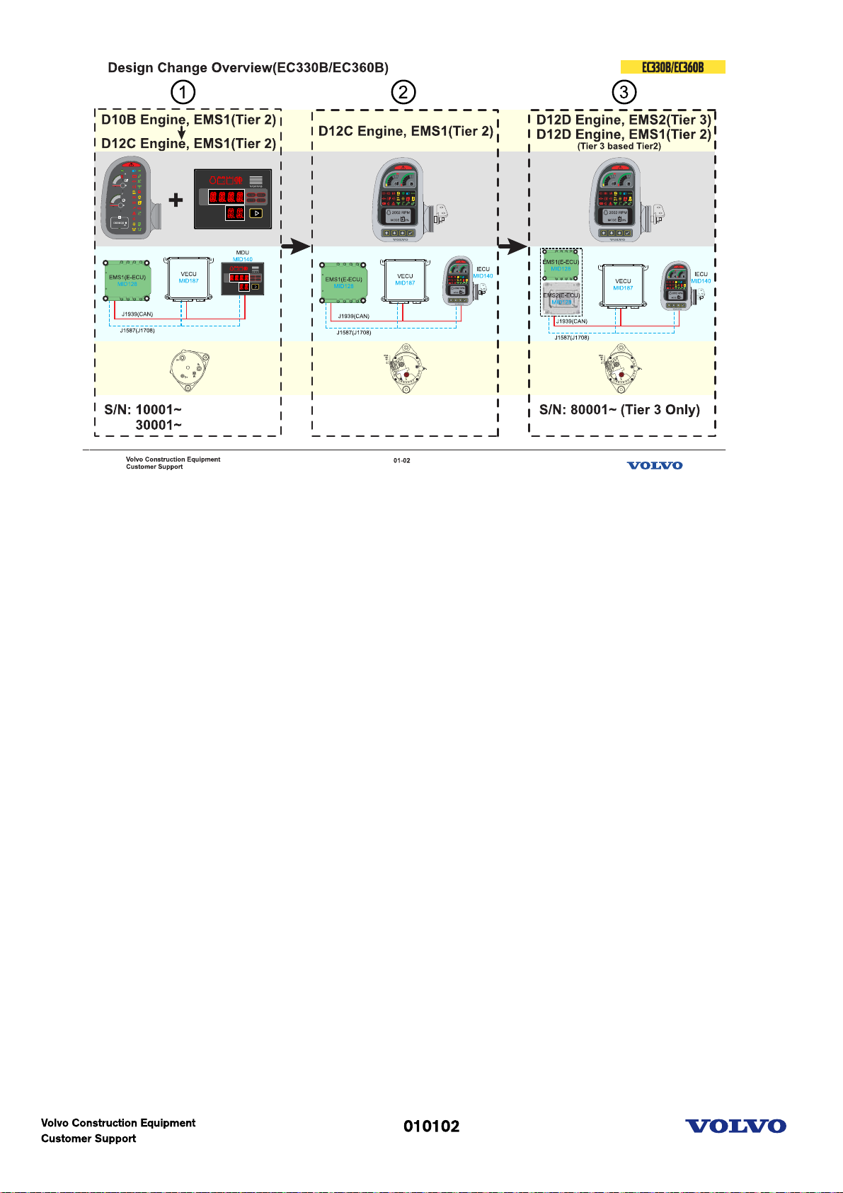
Design Change Overview(EC330B-EC360B)
1-Before I-ECU application
-D10B Engine, EMS1(Tier 2): Initial Production
-D12C Engine, EMS1(Tier 2)
-Instrument panel and MDU
-Old alternator
2-I-ECU application
-D12C Engine, EMS1(Tier 2)
-IECU(Programmable)
-New alternator
3-D12D application
-D12D Engine, EMS2(Tier 3): EU & NA only. Machine serial number starts from 80001
-D12D Engine, EMS1(Tier 3 based Tier 2): International region
-IECU(Programmable)
-New alternator
Picture text:
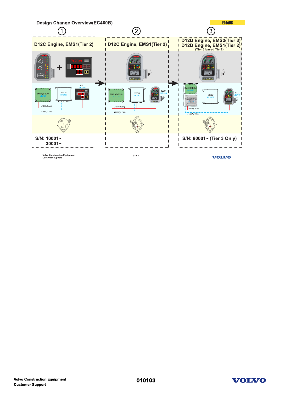
Design Change Overview(EC460B)
1-Before I-ECU application
-D12C Engine, EMS1(Tier 2)
-Instrument panel and MDU
-Old alternator
2-I-ECU application
-D12C Engine, EMS1(Tier 2)
-IECU(Programmable)
-New alternator
3-D12D Engine application
-D12D Engine, EMS2(Tier 3): EU & NA only. Machine serial number starts from 80001.
-D12D Engine, EMS1(Tier 3 based Tier 2): International region
-IECU(Programmable)
-New alternator
Picture text:
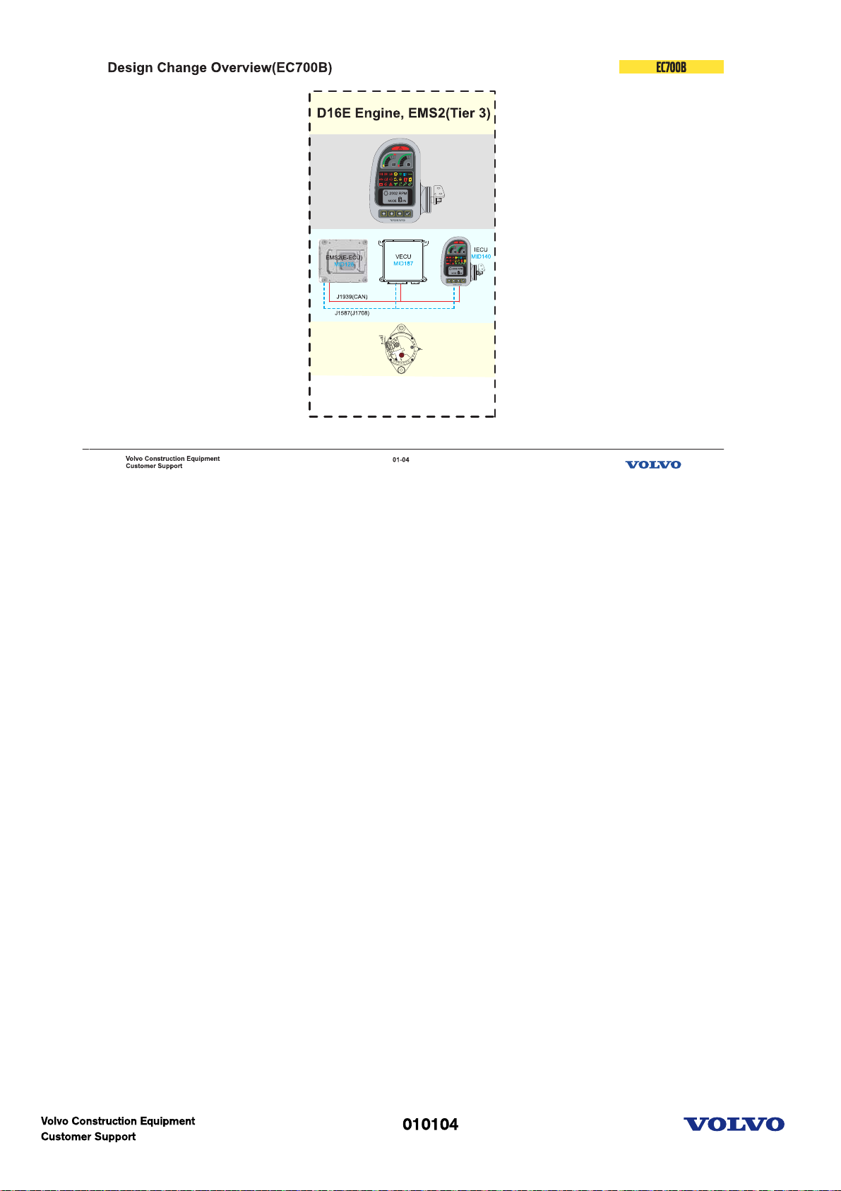
Design Change Overview(EC700B)
-D16E Engine, EMS2(Tier 3)
-IECU(Programmable)
-New alternator
Picture text:
Engine(D10B)
Picture text:
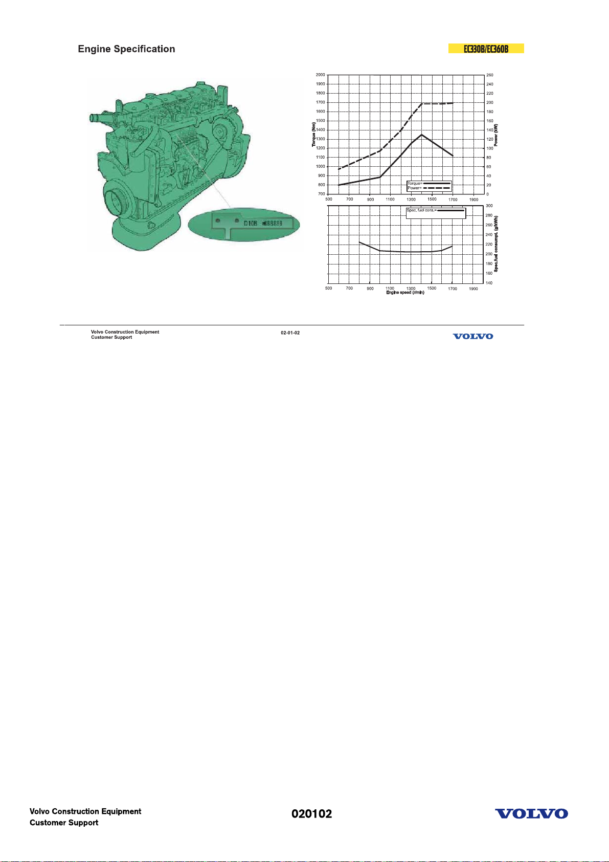
Engine specification
Model: D10B EAE2
Power(kW): 198 at 1700 rpm
Power(hp): 269 hp at 1700 rpm
Torque: 1345 Nm at 1400 rpm
Bore x Stroke: 120.65mm x 140mm
DISPLACEMENT: 9600 cc
Type: 4 cycle-diesel-turbo & charge air cooled
Picture text:
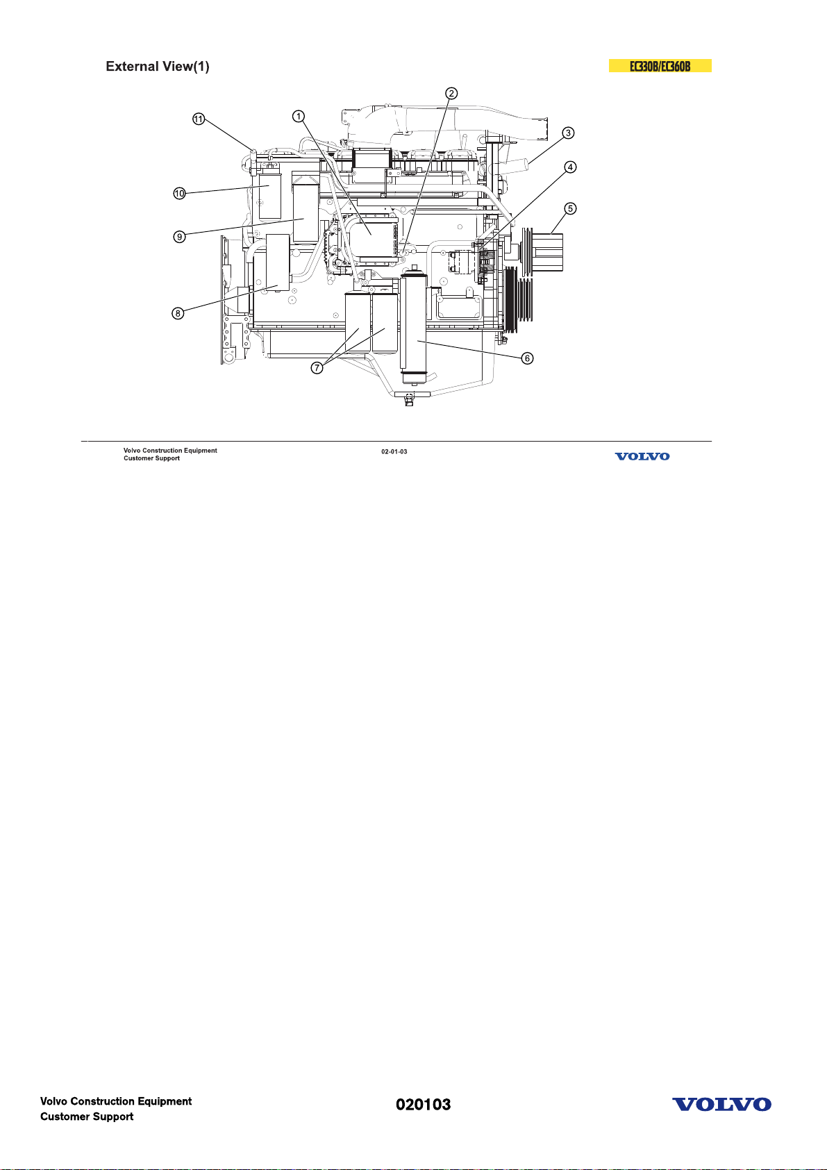
External view(1)
1. EMS(E-ECU)
2. Fuel inlet
3. Water outlet
4. Engine PTO
5. Fan drive & Pulley
6. Engine oil cooler
7. Engine oil filter(full)
8. Breather
9. Engine oil filter(bypass)
10. Fuel filter
11. Fuel feed pump
Picture text:
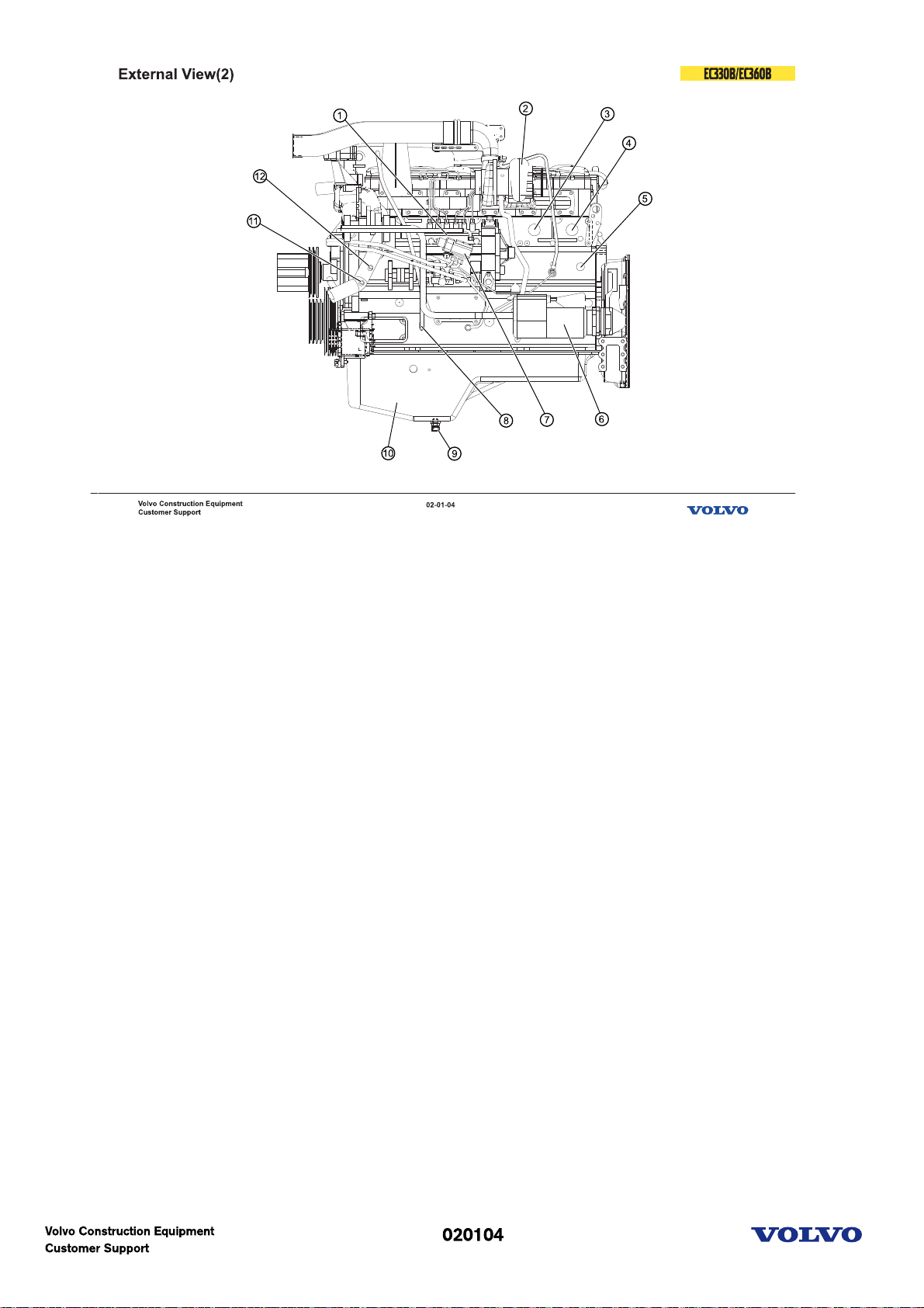
External view(2)
1. Fuel pump
2. Turbochargher
3. Cooler block heater
4. Cab heater supply
5. Coolant filter heater
6. Starter
7. Fuel shut-off solenoid
8. Dipstick
9. Oil drain valve
10. Oil pan
11. Coolant filter return
12. Cab heater return
Picture text:
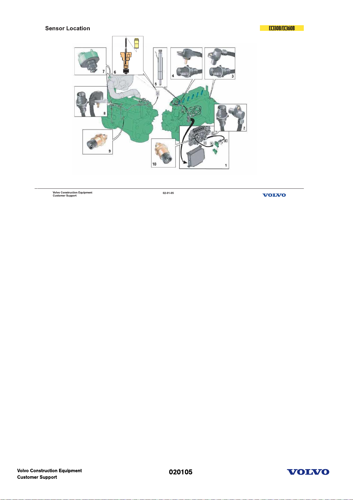
E-ECU Sensors
1. E-ECU
2,3. Speed sensor
4. Coolant temp.
5. Needle movement
6. Coolant level
7. Inlet air press. & temp.
8. Boost air press. & temp.
9. Oil press. & temp.
10. Fuel press. & temp.
Picture text:
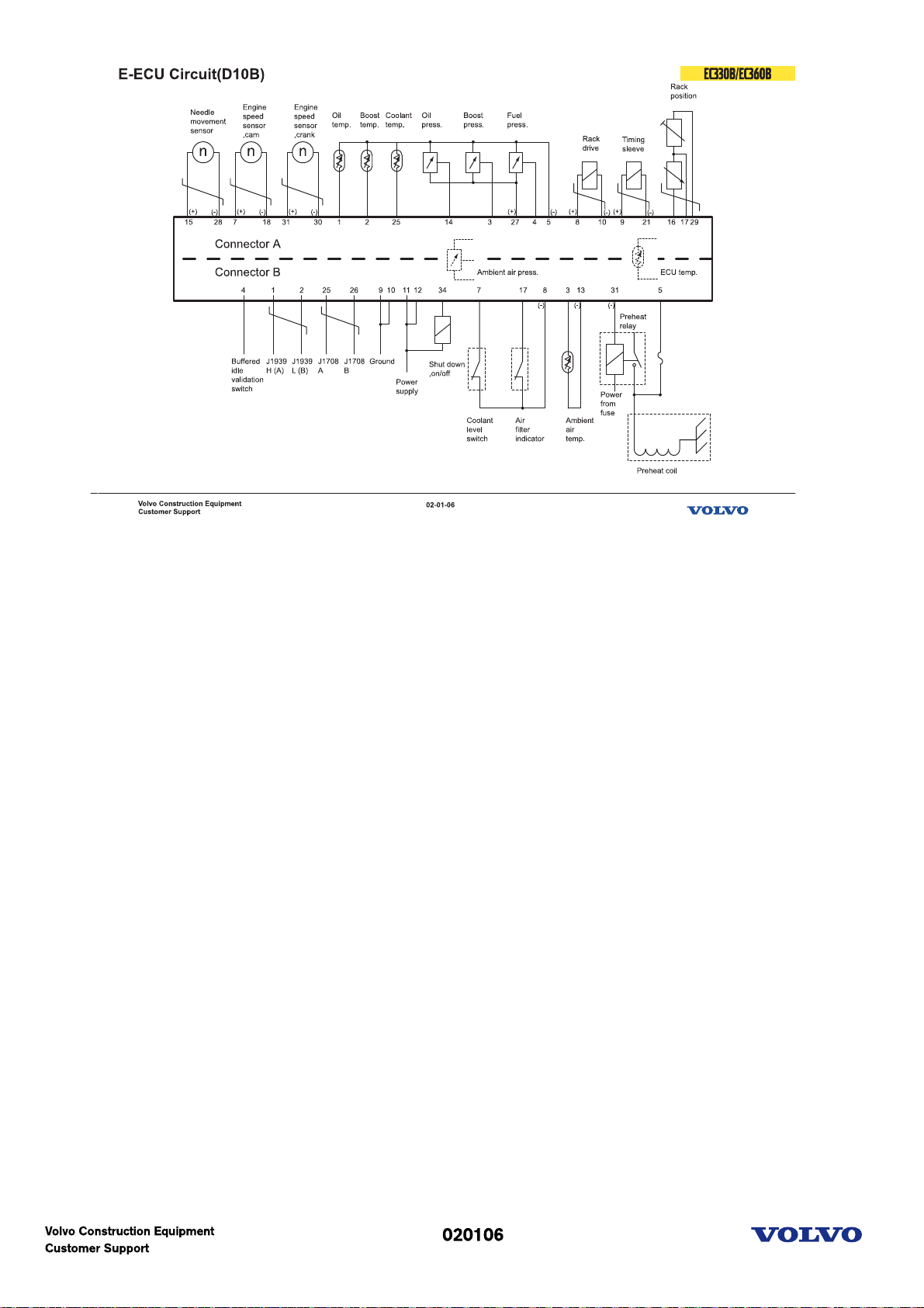
E-ECU circuit
Communication line is at the Red color connector!(Connector B)
Picture text:
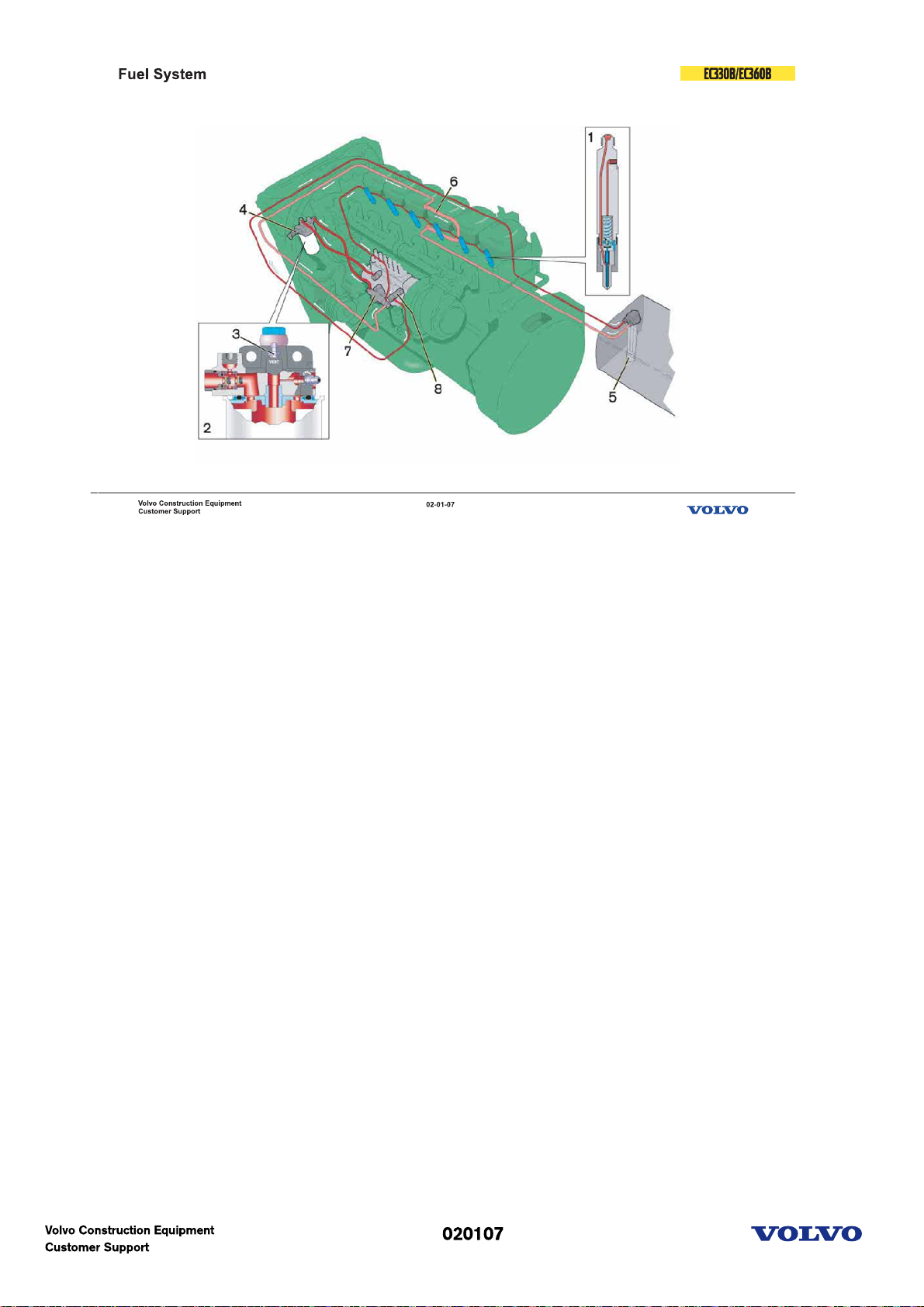
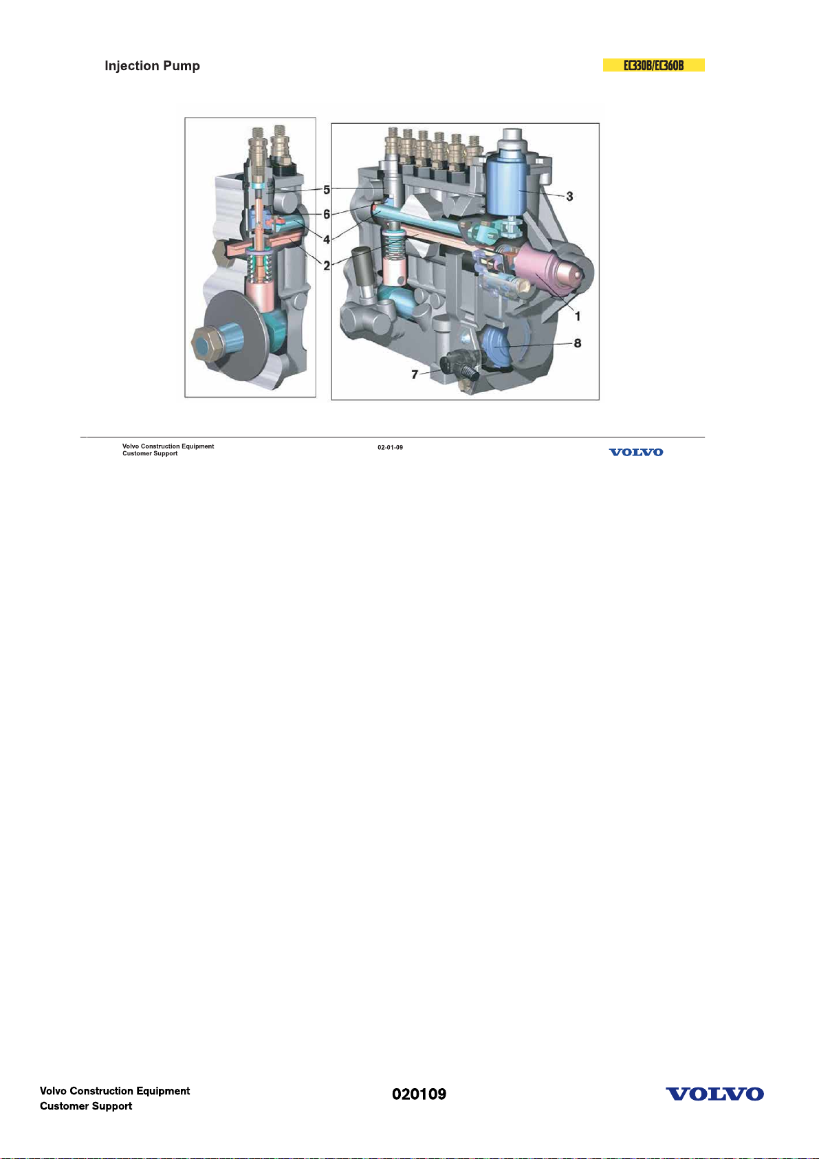
Fuel system
The injection pump is bolted onto a separate bracket on the left side of the engine.The injectors (1) used
are made by Bosch. Their opening pressure is adjusted by means of washers of varying thickness inserted
above the spring.
The fuel filter (2) is attached to a filter bracket. A bleeder nipple is also placed on the bracket (3).
From the feeder pump fuel is forced through the filter and into the injection pump feed side via the fuel
shut-off valve. Return fuel from the injection pump goes via the fuel shut-off valve and overflow valve (8)
to the tank. The leak-off line from the injectors is connected to the injection pump via the suction line
connection.
1. Injector
2. Fuel filter
3. Bleeder nipple
4. Sensor fuel temp/pressure
5. Tank strainer
6. Cooling loop, ECU
7. Feeder pump
8. Overflow valve
Picture text:
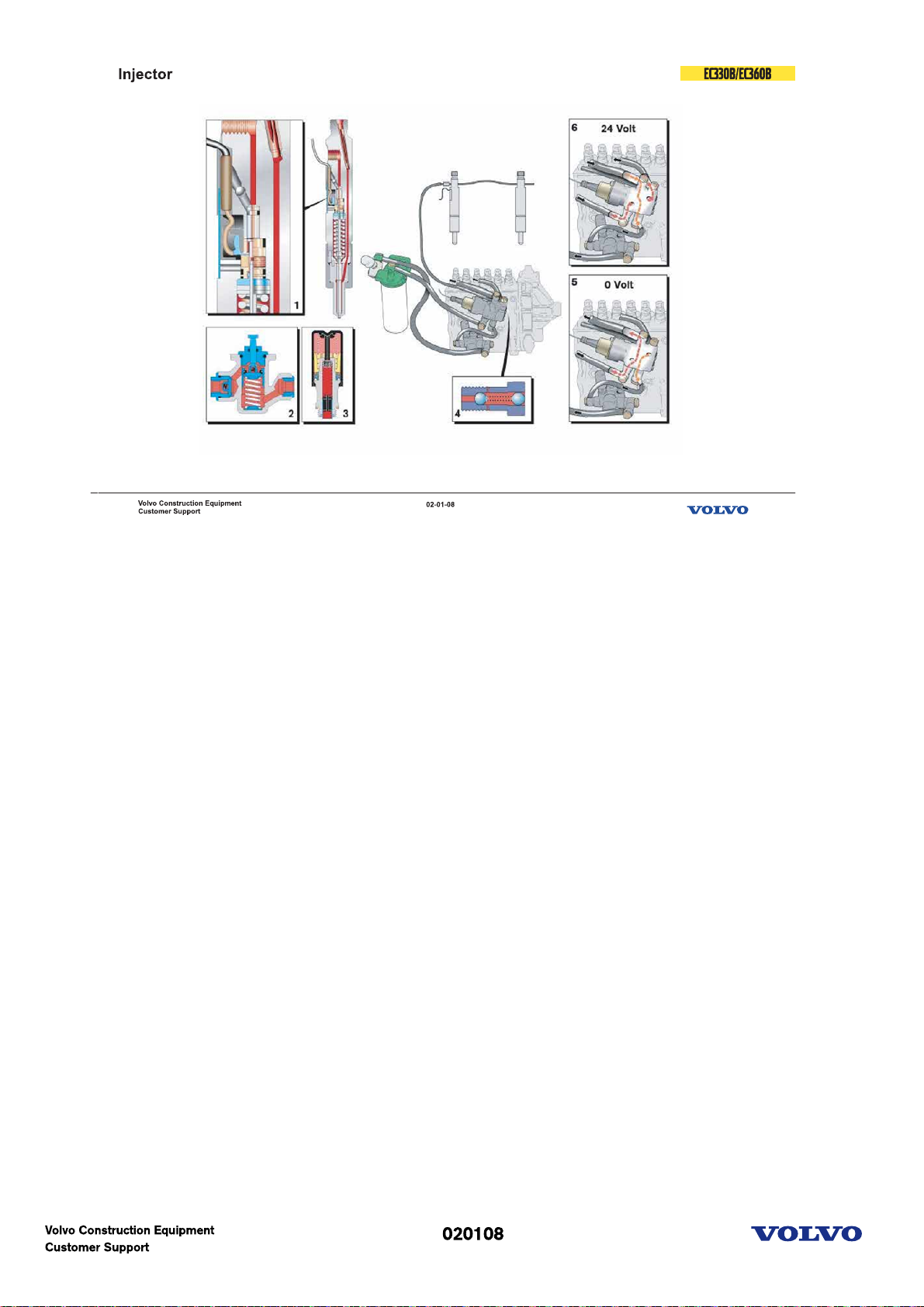
Fuel system-Injector
1 Needle movement sensor
2 Feed pump
3 Manual feed pump
4 Overflow valve
5 Fuel cut-off valve(Off condition)
6 Fuel cut-off valve(On condition)
Picture text:
Fuel system-Injection pump
1 Fuel rack control solenoid
2 Fuel rack(injection quantity control)
3 Injection timing control solenoid
4 Lever
5 Delivery valve
6 Timing sleeve
7 Speed sensor
8 Toothed wheel
Picture text:

Fuel system-Injection control
Injection timing is adjusted by timing sleeve location.
Injection quantity is adjusted by fuel rack operation.
Picture text:
Engine(D12C)
Picture text:
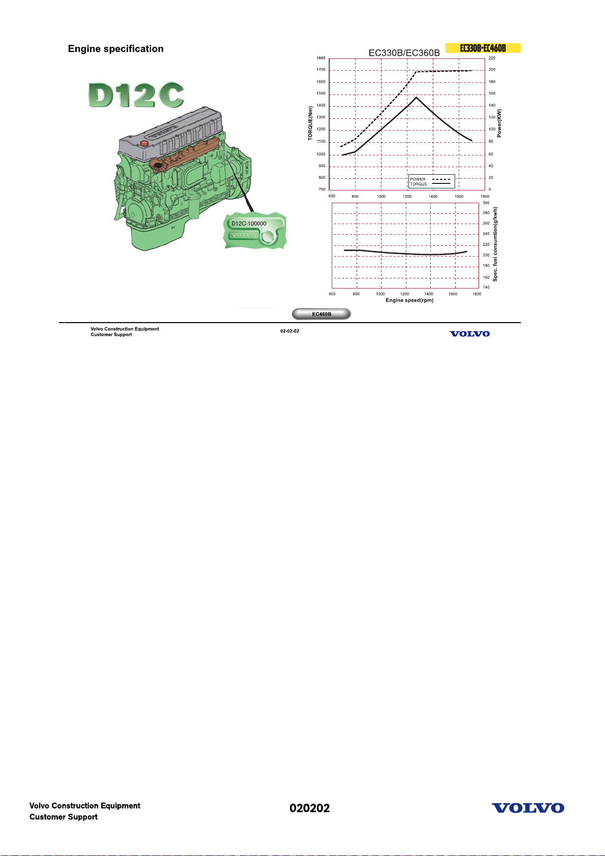
Engine specification
D=Diesel engine
12=Cylinder volume in litres
C=Generation
E=Excavator application
C=Version
E2= Valid to Tier-2 & Euro-2
1. EC330B-EC360B
D12CECE2(For NA), D12CEDE2(For EU), D12CEEE2(For other region)
Power: 198Kw at 1700rpm
MAX Torque: 1345Nm at 1400rpm
2. EC460B
D12CEAE2(For NA), D12CEBE2(For EU), D12CEFE2(For other region)
Power: 239Kw at 1900rpm
MAX Torque: 1600Nm at 1400rpm
D12 is the model number of the volvo 12 liter engine.
The engine is a 6-cylinder, 4-stroke, direct injection diesel with a 12 liter cylinder volume, turbocharger,
charged air cooler and electronic controlled fuel injection, EMS (Engine Management System).
The serial number of the engine is to be found stamped in the cylinder block on the rear left side.
The cylinder head is of cast iron and manufactured in one piece which is necessary in order to provide
stable bearings for the overhead camshaft.
The cylinder liner is sealed against the coolant casing with rubber rings.
The D12C has a four-valve system and overhead camshaft.
The engine timing gear transmission is located at the front of the engine on a 10 mm thick steel plate
bolted to the cylinder block.
The crankshaft is drop forged and has induction hardened bearing surfaces and fillets.
The engine is force fed lubricated by an oil pump which is gear driven from the engine crankshaft via an
intermediate gear
The fuel system for D12C has electronic control with unit injectors one for each cylinder and which operate
at a very high pressure.
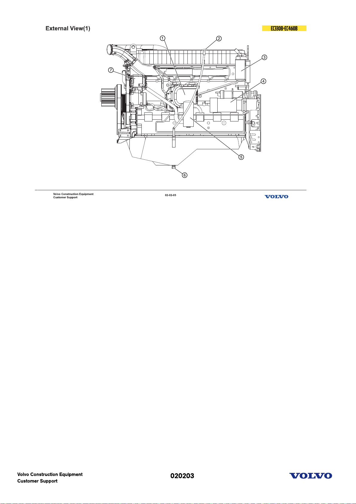
External view(1)
External view & component location
1. E-ECU
2. Dip stick
3. Fuel filter
4. Start motor
5. Breather
6. Oil drain valve
7. Alternator
Picture text:
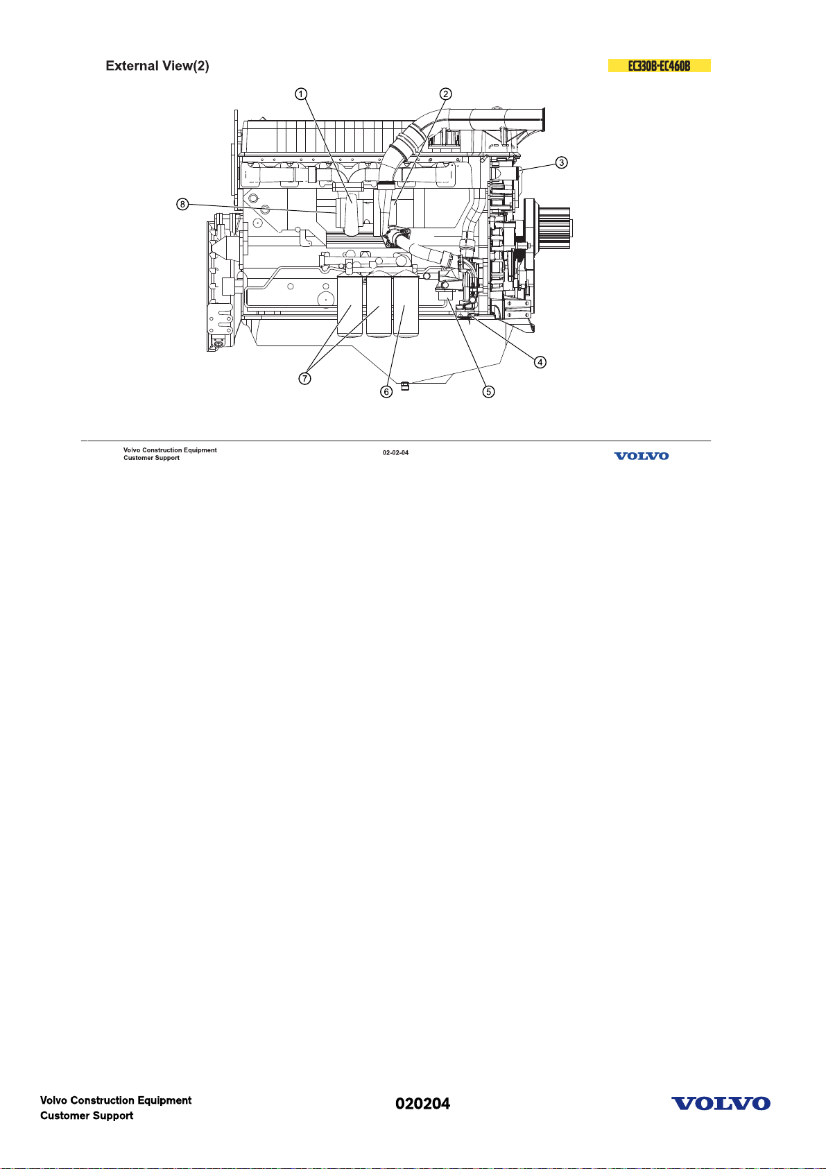
External view(2)
External view & component location
1. Turbocharger
2. Air inlet
3. Water outlet
4. Coolant filter connection
5. Water inlet
6. Oil filter(by-pass)
7. Oil filter(full flow)
8. Exhaust outlet
Picture text:
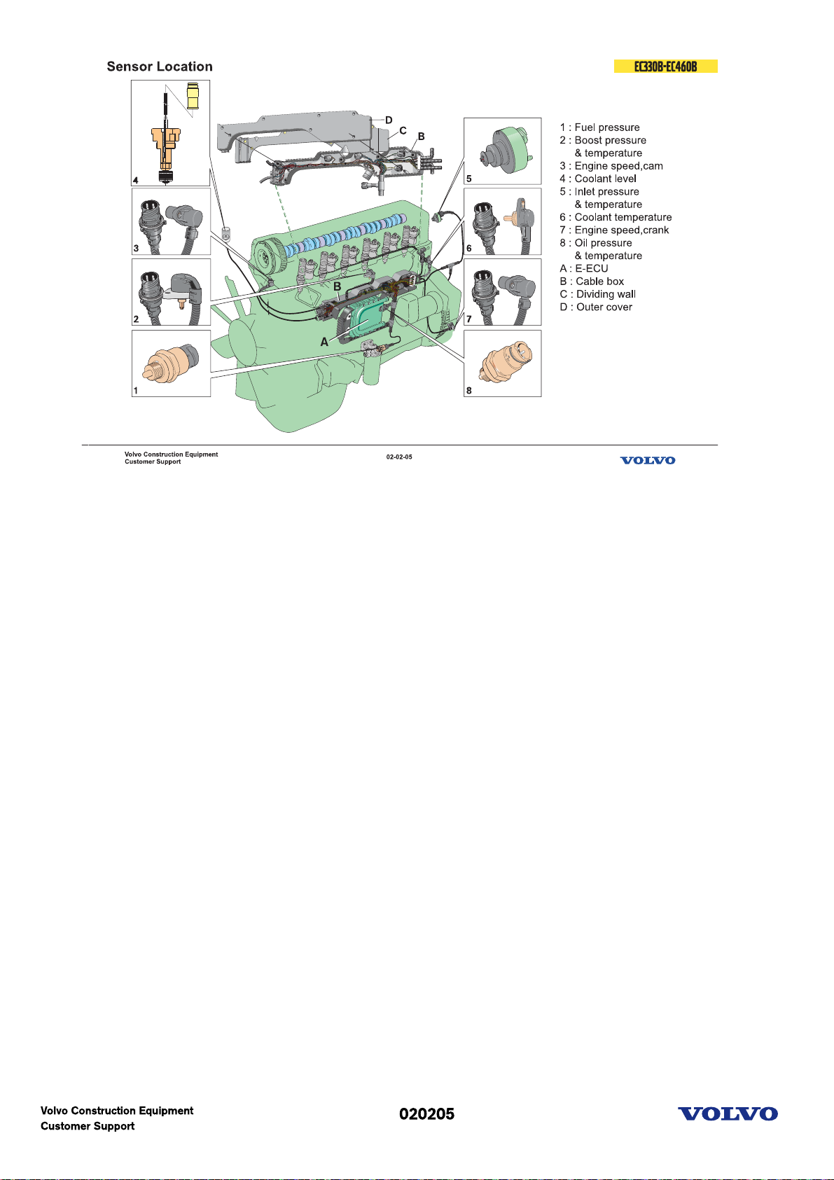
E-ECU Sensors
The D12C has a total of eight sensors. Three of these have dual functions. This gives a total of 11
functions.
The dual function sensors are:
2 Turbo boost pressure/air temperature in inlet manifold.
5 Air temperature before intercooler and pressure drop indicator. Located in the union pipe between the
air filter housing and the turbocharger inlet.
8 Oil pressure/temperature.
The other sensors are:
1 Fuel pressure sensor. Senses the pressure after the fuel filter.
3 Camshaft position sensor. Located in the upper timing mechanism cover.
4 Engine coolant level. Located in the expansion tank.
6 Engine coolant temperature. Located in the rear end of the cylinder head.
7 Engine speed sensor. Located in the fly wheel cover.
Apart from the sensors above, the system includes a sensor for Atmospheric Pressure, located inside the
EECU.
Picture text:
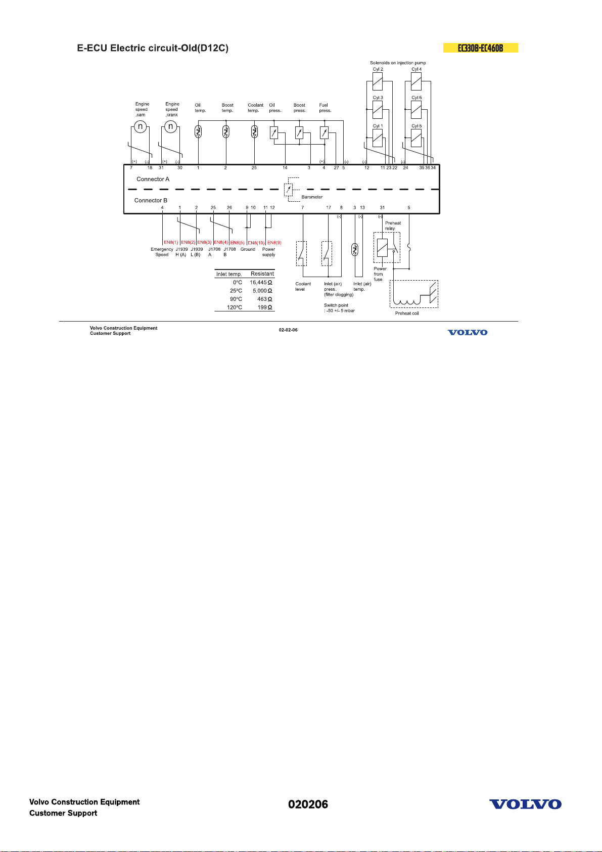
EECU electric circuit(Old)
Communication between the control units go via two data buses.
The two data buses have different functions. One is used for the control signals of system and is
designated SAE J1939.
The other databus, SAE J1708, is used for information and diagnostics. The link also functions as a back
up for the other databus if this for any reason does not function.
The Engine Management System (EMS) consists of a control unit (EECU) mounted to the engine, sensors
and a wiring harness. The EECU, Engine Electronic Control Unit, is connects to both the data bus SAE
J1939 and SAE J1708.
The unit receives signals from the Vehicle Control Unit, VECU.
It sends signals to control various functions on the engine and communicates with other control units via
the databuses.
Picture text:
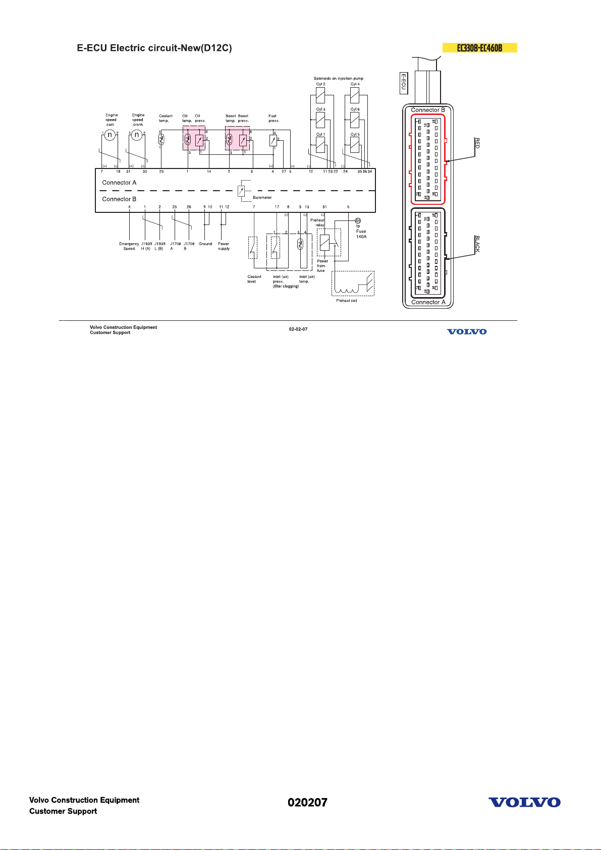
E-ECU Electric circuit(New)
New sensor
1. Oil temp. & oil pressure sensor
2. Boost temp. & boost pressure sensor
Picture text:
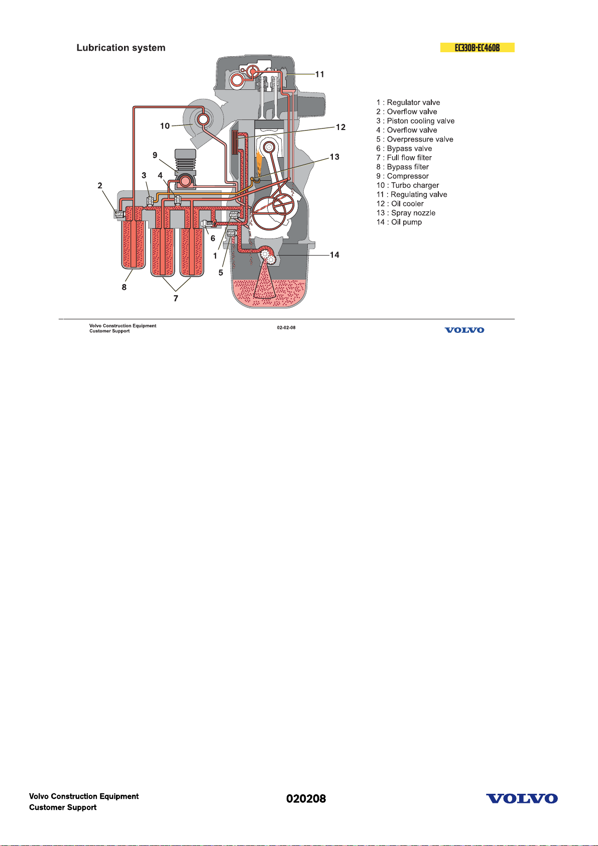
Lubrication system schematic
This is a schematic description of the lubricating system.
When the engine starts the gear driven pump forces the lubricating oil in to the filter housing. At low oil
temperature, for example when cold starting in the winter the bypass valve for the oil cooler will open so
the oil will reach the engine faster. From the full flow filters the oil is distributed to the bypass filter and
the engine block gallery then to all the engine lubricating points.
The turbo charger is lubricated with oil directly from the bypass filter.
The air compressor is lubricated via an external hose from the filter housing.
Oil return from the cylinder head
There are three oil return holes drilled through the cylinder head and block.
Oil pressure reducing
The regulator valve regulates the engine oil pressure and excess oil is led back to the sump.
Piston cooling
The valve for piston cooling is pressure sensitive and opens just above the normal idling pressure. The oil
is led in to the lengthways channel in the block and sprayed via nozzle, one for each piston, onto the
inside of the piston.
By-pass filter Overflow
The overflow valve for the bypass filter opens if the filter becomes blocked to ensure turbo lubrication.
Full flow filter Overflow
The overflow valve for the full flow filter opens if the filter becomes blocked to ensure engine
lubrication. Oil cooler bypass
When the engine starts and the oil temperature is low (low viscosity), the oil cooling bypass valve opens.
This is to lubricate the engine faster during cold start. When the oil temperature is stabilized (viscosity)
the valve closes and the oil passes through the oil cooler.
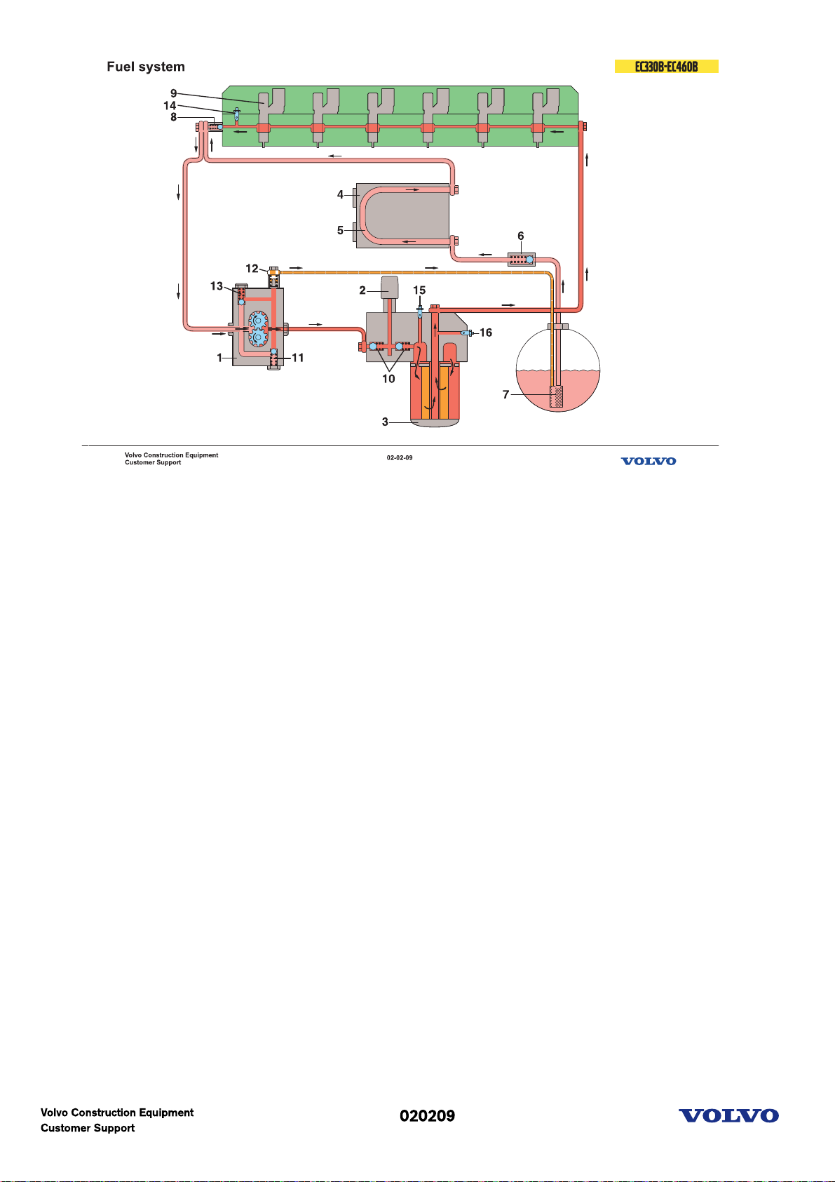
Fuel system principle
The fuel flow and valve function is schematically described. Light red means suction and dark red means
feed pressure.
The fuel is sucked up by the feeder pump (1) through the strainer (7) in the tank fitting, past the nonreturn valve (6).The non-return valve opens and the fuel flows to the control unit and goes through the
cooling loop (5) ( if the control unit (4) has cooling ) up to the overflow valve (8) and from there, together
with the return fuel which passes through the overflow valve to the feeder pump suction side.
The feeder pump (1) forces the fuel to the filter housing, past both of the non-return valves (10) for the
hand pump (2) and at the same time valve (12) opens for the return fuel to the tank. If there is some air
in the system it will automatically be bleeded.
After through the filter (3), to the cylinder head lengthways channel to feed the injectors (9).
The overflow valve (8) maintains a constant pressure for the fuel feed to the injectors (9) and opens at the
pressure of 3,5 to 4,5 bar.
The pressure regulating valve (11) in the pump opens to reduce the pressure in the pump for example
during engine braking when the fuel injection is cut off.
Picture text:
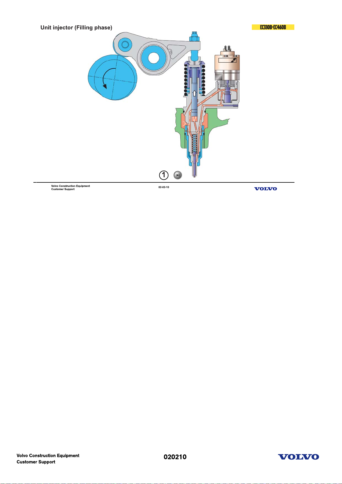
Unit injector
The unit injector
The unit injector is driven by the engine camshaft via a rocker arm. Simply put, a unit injector is a
combination of an injection pump and a conventional injector and it consists of three main sections:
the pump section(1)
the valve section with the solenoid(2)
the injection section(3)
The pump piston pumps a constant quantity of fuel back and forth through the injector and there is no
injection as long as the injector solenoid keeps the valve open.
1. Filling phase
This occurs the entire time that the pump piston is on the way up. The fuel valve is open since there is no
voltage applied to the solenoid valve. Fuel can therefore be sucked from the feeder channel, past the
open valve and into the pump cylinder.
2. Spilling phase
The pump piston is on the way down. As long as there is no voltage to the solenoid valve, the fuel valve is
open and the fuel flows back in return to the feeder channel.
3. Injection phase
The pump piston is still on the way down. Now the solenoid valve has received voltage from the control
unit. The valve cone is lifted and the valve closes. Since fuel cannot pass through the valve, a pressure is
quickly built up which lifts the nozzle needle and injection occurs.
Injection continues as long as the valve is closed and the pump piston is on the way down.
The injection timing and fuel quantity is determined by the length of the electrical pulse. It is the control
unit which determines the pulse size via the information it receives from the control system.
4. Pressure reducing phase
The pump piston is still on the way down. The control unit ends the electrical pulse when the engine has
received the amount of fuel needed at that instant. The fuel valve opens and the fuel can once again flow
past in return to the feed channel. The pressure then drops quickly and the nozzle needle closes.

Engine(D12D)
Picture text:
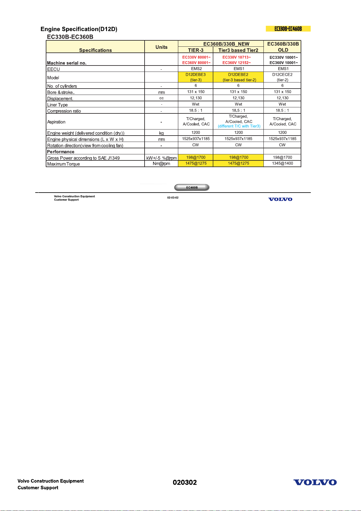
Engine specification (D12D)
EC330B-EC360B
Excavator uses the D12DEBE3 & D12DEBE2.
For those 2 engines, external layout (fuel line, cooling, inlet & exhaust, mounting) is almost same but
internal components (ECU, Unit injector, Piston etc.) are totally different.
Machine with D12DEBE3 has new serial number started with 80001 and will cover EU & NA region.
EC460B
Excavator uses the D12DEAE3 & D12DEAE2.
For those 2 engines, external layout (fuel line, cooling, inlet & exhaust, mounting) is almost same but
internal components (ECU, Unit injector, Piston etc.) are totally different.
Machine with D12DEAE3 has new serial number started with 80001 and will cover EU & NA region.
Picture text:
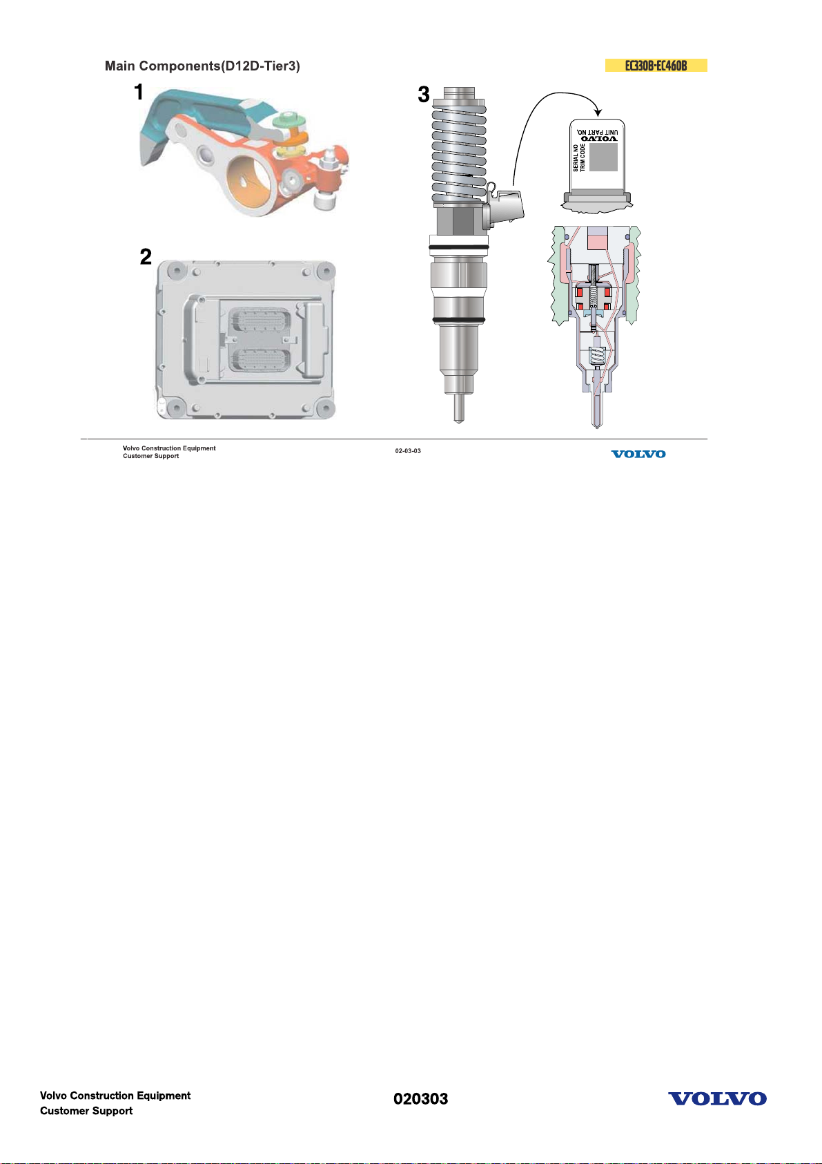
Main components
1.The IEGR double rocker has an extra arm, the follower arm, which creates a small second exhaust valve
lift. This extra lift feeds exhaust gases back into the cylinder during the inlet stroke.
2.The most advanced Volvo engine controller, EMS2, will be utilized to provide the highest level of
electronic features and to enhance reliability.
3.The proven new high-pressure dual solenoid diesel fuel injector, Delphi E3, introduced with the Volvo
U.S. EPA 2002 highway engine, is an integral part of the V-ACT (Volvo Advanced Combustion Technology)
system.
**When replacing the injector, we need parameter programing for trim code with VCADS Pro.
Picture text:
1. Switch Able Internal EGR Double Rocker
2. Engine Management System Controller EMS2
3. High-pressure dual solenoid fuel injector Delphi E3
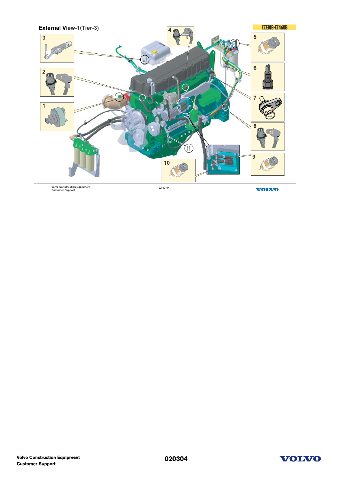
External view-1(Tier-3)
1. Inlet air temp. & pressure sensor
2. Cam speed sensor
3. Coolant level sensor
4. Boost press. & temp. sensor
5. Fuel feed pressure sensor
6. Water in fuel sensor
7. Coolant temp. sensor
8. Crank speed sensor
9. Engine oil press. sensor
10. Crankcase pressure sensor
11. PTO
Picture text:
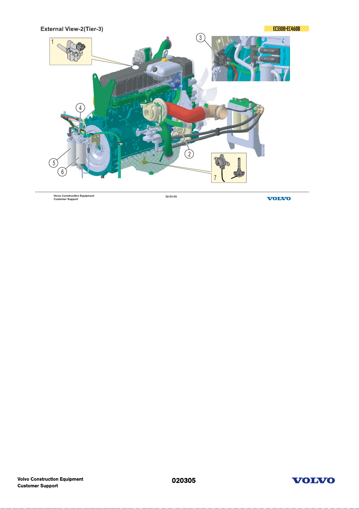
External view-2(Tier-3)
1. IEGR solenoid
2. Coolant pump
3. Fuel feed pump
4. Fuel lift pump
5. Fuel filter
6. Water seperator
7. Engine oil level & temp. sensor
Picture text:
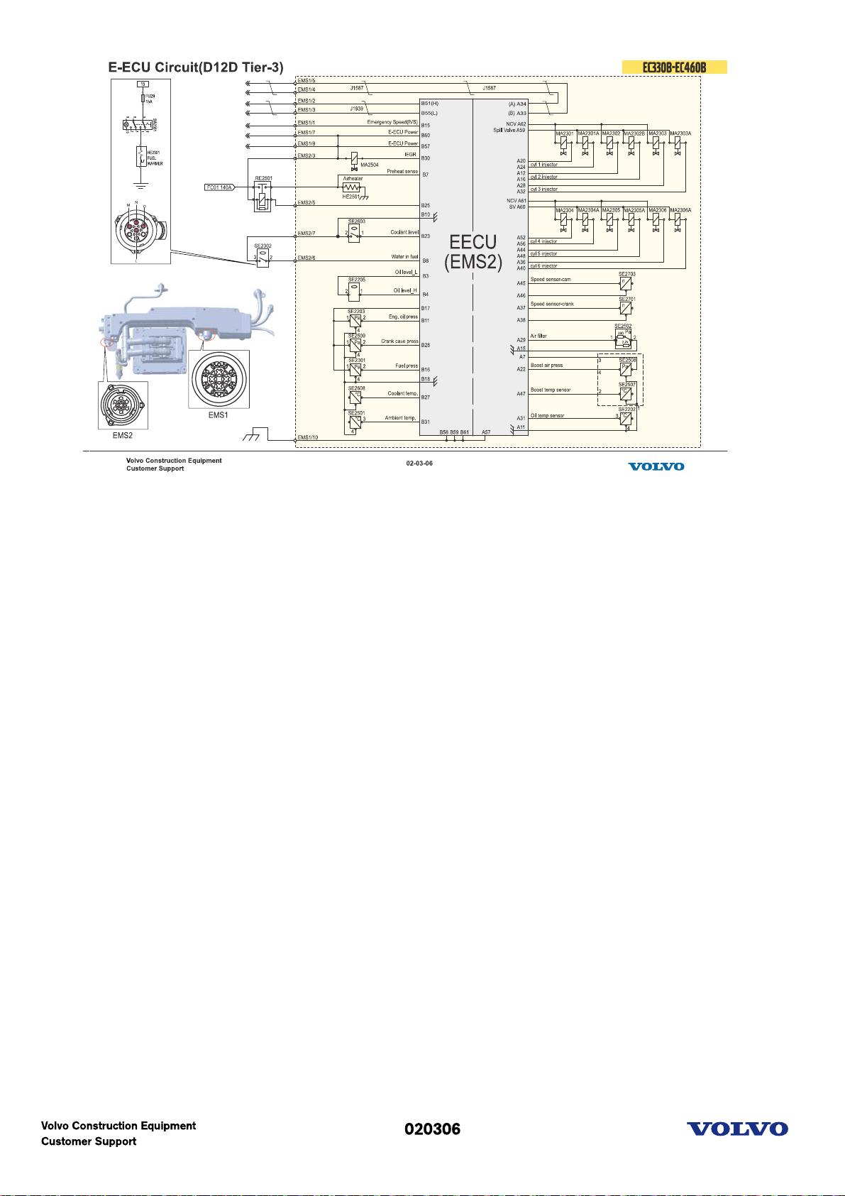
E-ECU circuit (D12D, Tier-3)
Picture text:

Main components (D12D, Tier-3 based Tier-2)
EMS1 & Delphi E1 injector
Picture text:

Sensors location (D12D Tier 3 based Tier2)
The picture shows all D12D engine sensors. Inside the EECU there are also sensors for ambient air
pressure and the EECU temperature.
The sensors differing, compared with the D12C engine, are the crankcase pressure sensor (new), oil
pressure sensor (before a combined pressure and temperature sensor), water in fuel sensor (new) and oil
level and temperature sensor (before only a level sensor).
Picture text:
1. Crankcase pressure sensor
2. Coolant level sensor
3. Camshaft speed sensor
4. Oil pressure sensor
5. Charge air pressure and temperature sensor
6. Air pressure and temperature sensor
7. Fuel pressure sensor
8. Water in fuel sensor
9. Coolant temperature sensor
10. Crank shaft speed sensor
11. Oil level and temperature sensor

E-ECU circuit(D12D, Tier 3 based Tier 2)
Picture text:

Fuel system
The fuel is drawn with help of the fuel feed pump (1) through the tank unit (2), via fuel pre- filter (4) and
water separator (5) into the fuel filter housing (3).
The fuel is then routed through the engine ECUs cooling loop (6) to the overflow valve (7), where the
fuel from the tank is mixed with the fuel returned from the fuel channel (8) in the cylinder head, and then
forward to the suction side of the fuel feed pump (1). The fuel feed pump (1) press fuel to the fuel filter
housing (3), through the main filter (9) to the cylinder head fuel channel (8). This channel provides every
unit injector (10) with fuel via a ring formed passage around every unit injector in the cylinder head. The
overflow valve (7) regulates the fuel feed pressure to the unit injectors.
Fuel feed pump valves
The fuel feed pump has two valves: Safety valve (11), which allows fuel to flow back to suction side when
the fuel pressure become too high e.g. when the fuel filter is clogged. Check valve (12) opens when the
hand pump in the filter housing (13) is used.
Automatic deaeration
If air has entered the system, automatic deaeration occurs when the engine is started. The air is pushed
through the deaeration valve (14) down to the tank via the fuel return hose (15) from cylinder head.
Deaeration of fuel filters when changing filters is controlled by the valves (19), (25) and (14) in the filter
housing.
Manual hand pump
The manual hand pump (13) in the filter housing is used to pump fuel (non-running engine), when the fuel
system is empty. The check valve (24) for the hand pump is placed within the fuel filter housing.
Manual water drain
WIF (water in fuel) sensor (16) will via the ECU give an indication on the instrument panel. This indicates
that it is necessary to manually drain the water-separator (5) using the drain valve (18).
Miscellaneous
(20) Fuel pressure measuring point used for fault localization
(21) Pressure indicator
(22) Optional bowl heater

IEGR(V-ACT)
NOx reduction solution is provided by Internal Exhaust Gas Recirculation (IEGR) which is altering engine
valve lift.
Picture text:

Delphi E3 function(Tier-3)
1. Neither the spill valve (SV) nor the needle control valve (NCV) solenoid is electrically activated. The
return spring is forcing the SV to its upper position and the NCV to its lower position. In this position the
SV is open and the fuel are routed from the pump chamber back into the low pressure fuel feed line and
no internal pressure build-up occurs in the high pressure fuel line. In this position the NCV is closed
connecting the needle backing chamber with the high pressure fuel line, but as the SV is open there is no
pressure build behind the needle.
2. The SV solenoid is electrically activated and the SV is pulled downwards closing the connection to the
low pressure feed line. In this position the SV is closed and all fuel is forced from the pump chamber via
the high pressure fuel line. The fuel pressure increases acting on the injection needle lift area. The NCV is
still not activated (still closed) connecting the needle backing chamber with the high pressure fuel line,
why the needle can not be lifted.
3. The SV is still closed and the fuel pressure is still increasing. When the desired pressure is achieved, the
NCV is activated (opened), closing the high-pressure line connection to the backing chamber of the needle
and at the same time connecting the chamber to the low pressure line. The pressure on the lift side, now
higher than required to overcome the closing force from the needle closing spring, opens the needle and
injection occurs until the NCV is closed or until the SV is opened.
In this way the needle opening pressure can be varied between the preset NOP of the spring and the
maximum pumping pressure. Practically the levels used are between 250 to 1800 bars, to be compared
with a common nozzle, using 250 to 350 bar opening pressure.
Picture text:

Delphi E3 needle lift
A. The spill valve is electrically activated and closes; fuel is forced from the pump chamber via the high
pressure fuel line acting on the injection needle lift area.
B. The fuel pressure increases and reaches the pressure required to overcome the closing force from the
needle closing spring, but as the NCV is still open the needle can not lift.
C. The fuel pressure reaches the desired needle opening pressure.
D. The NCV is electrically activated and opens; the fuel pressure in the needle backing chamber is
evacuated allowing the needle to lift.
E. The injection needle is lifted.
F. The fuel amount required is now injected and the NCV is deactivated, closed. The needle backing
chamber is now again connected to the high pressure fuel line and the needle is forced to close.
G. The needle closes and injection ends.
H. As the SV is still closed the pressure continues to increase as long as the pump piston is moving
downwards.
I. The spill valve is deactivated, opened. The fuel is routed into the low pressure feed line.
J. The fuel pressure is evacuated to the low pressure feed line via the open SV.
Picture text:
1. Needle lift
2. Needle opening pressure, desired
3. Needle opening pressure, spring
4. Fuel pressure
5. Spill valve (SV)
6. Needle control valve (NCV)

Valve lash adjustment(1)
The below lashes is to be set when the engine is cold, approx. 20-25 °C.
Engine IEGR Exhaust
valve lash valve lash (mm)
D12D Gauge 0.7
88820003
Rotate the camshaft and position it according to the marking for the cylinder being adjusted. The marking
on the camshaft shall be placed between the two marks on the front camshaft bearing cap
Before checking the double rocker arm clearance, adjust the exhaust valve lash (also inlet valve lash and
preload the injector) according to normal procedure
Loosen the oil drain nipple (3).
Loosen the lock nut (1) and counter hold the piston (2) with an internal 4 mm Allen head key.
Picture text:
1. Nut (lock)
2. Piston
3. Oil drain nipple

Valve lash adjustment(2)
1. Adjustment
Insert a special adjustment gauge (A) tool (P/N: 88820003-1) between the follower arm contact surface
and the cam base circle.
Turn the hex key until the gauge is squeezed tight between the cam lobe and the follower arm contact
surface.
Tighten the nut (B), while piston (C) is kept in position.
Tighten the oil drain nipple.
2. Inspection
Insert a special go/no go gauge tool (D) (P/N: 88820003-2) between the follower arm contact surface and
the cam base circle. The go gauge side (F) must pass through between the follower arm surface and the
cam base circle; if not the IEGR lift will be too big.
Insert the opposite, no-go, side (E) between the follower arm contact surface and the cam base circle. The
no-go gauge side must not pass through; if it does the IEGR lift will be too small.
If the IEGR valve lash does not pass the inspection, the lash has to be readjusted.
Picture text:
1. Nut (lock)
2. Piston

Engine protection function
Excavator are using only basic protection function.
Picture text:

Engine(D16E)
Model: D16EEAE3
Rated output: 346kW @ 1800rpm
Picture text:

Engine specification
Unit Injector type
-------------------------------------EC700B : D16E EAE3
Type: 4 cycle, Diesel, Turbo charged, Air to Air After cooled
No.of cylinder : 6 vertical in line type
Bore X Stroke: 144mm X 165mm
Max. Power(fan not in operation)
346kW@1800rpm
Max. Torque(fan not in operation)
2500Nm@1080rpm
Governor type: EMS2
Displacement: 16100cc
Emission : Tier3
Picture text:

Main components
1.The IEGR double rocker has an extra arm, the follower arm, which creates a small second exhaust valve
lift. This extra lift feeds exhaust gases back into the cylinder during the inlet stroke.
2.The most advanced Volvo engine controller, EMS2, will be utilized to provide the highest level of
electronic features and to enhance reliability.
3.The proven new high-pressure dual solenoid diesel fuel injector, Delphi E3, introduced with the Volvo
U.S. EPA 2002 highway engine, is an integral part of the V-ACT (Volvo Advanced Combustion Technology)
system.
**When replacing the injector, we need parameter programing for trim code with VCADS Pro.
Picture text:
1. Switch Able Internal EGR Double Rocker
2. Engine Management System Controller EMS2
3. High-pressure dual solenoid fuel injector Delphi E3

External view(1)
1. Crankcase pressure sensor
2. Engine oil temp. & Level
3. Engine oil press. sensor
4. Water in fuel sensor
5. Fuel feed pressure sensor
6. Boost press. & temp. sensor
7. Fuel feed pump
8. Breather
Picture text:

External view(2)
1. Crank speed sensor
2. Cam speed sensor
3. Coolant temp. sensor
4. Coolant level sensor
5. Inlet air temp. & Pressure
Picture text:

Electric circuit (D16E)
Picture text:

Fuel system
The fuel is drawn with help of the fuel feed pump (1) through the tank unit (2), via fuel pre- filter (3) and
water separator (4) into the fuel filter housing (5).
The fuel is then routed through the engine ECU cooling loop (6) to the distribution housing (7), where the
fuel from the tank is mixed with the fuel returned from the fuel channel (8) in the cylinder head, and then
forward to the suction side of the fuel feed pump (1). The fuel feed pump (1) press fuel to the fuel filter
housing (5), through the main filter (9) to the cylinder head fuel channel (8). This channel provides every
unit injector (10) with fuel via a ring formed passage around every unit injector in the cylinder head. The
overflow valve (11) regulates the fuel feed pressure to the unit injectors.
Fuel feed pump valves
The fuel feed pump has two valves: Safety valve (13), which allows fuel to flow back to suction side when
the fuel pressure become too high e.g. when the fuel filter is clogged. Check valve (14) opens when the
hand pump in the filter housing (15) is used.
Automatic deaeration
If air has entered the system, automatic deaeration occurs when the engine is started. The air is pushed
through the air bleed valve (11) down to the tank via the fuel return hose from cylinder head. Deaeration
of fuel filters when changing filters is controlled by the valves (16) and (17) in the filter housing.
Manual hand pump
The manual hand pump (15) in the filter housing is used to pump fuel (non-running engine), when the fuel
system is empty. The check valve (18) for the hand pump is placed within the fuel filter housing.
Manual water drain
WIF (water in fuel) sensor (19) will via the ECU give an indication on the instrument panel. This indicates
that it is necessary to manually drain the water-separator (4) using the drain valve.
Picture text: A: from fuel tank
B: to ECU cooling
C: from fuel pump

I-EGR Valve operation
Picture text:

1
Valve adjustment
1)
- Loosen the hexagon screws that hold the leaf springs.
The screws are to be loosened on all six cylinders.
- Rotate the cam shaft to adjust the rocker arms.
- The dash marking on the cam shaft must be positioned between the two dash marks on the bearing
housing.
- Adjust all rockers(in,ex,injector) for that cylinder per number! Cylinder 1
shown.
2)Adjust the inlet rocker arm clearance.
- Set the clearance between the rocker arm ball socket and the valve caliper to 0.3 mm using the
adjusting screw on the rocker arm and a feeler gauge.
(Torque to tighten the nut : 38 Nm)
A : Inlet
B : Injector
C : Exhaust
3)
- Eliminate the clearance between the adjusting screw and the injector by turning the adjusting screw.
- Turn the adjusting screw another 240º (4 hexagons : 180 + 60).
- Torque to tighten the nut : 52 Nm
4)
- The valve caliper must be balanced before adjusting the exhaust rocker arm clearance.
- Adjust the clearance between the exhaust rocker arm ball socket and the valve caliper to 0.60mm, using
the adjusting screw on the rocker arm and a feeler gauge.
- Torque to tighten the nut : 38 Nm
5)
- Loosen the nut on the brake rocker arm.
- Place a dial indicator on the feeler gauge, close to the ball socket, and set the dial indicator to zero.
- Tighten the adjusting screw with a hexagon key until the dial indicator shows that the valve yoke has

Air intake system
(1) Rain cover + Filter
(2) Pre-cleaner with scavanger + Filter
(3) Oil bath type pre-cleaner + Filter
A: check valve
Picture text:

Electric system(Before I-ECU)
EC330B-EC460B
Picture text:

Engine start and stop circuit
If battery disconnection switch is off position, we cannot use the whole of electric system.
When master switch (Battery disconnection switch) is ON, we can use Room lamp, diesel heater, fuel filler
pump, DC-DC converter, Auto greasing system without the key.
When the start switch is ON position,
BR signal turn on the battery relay. From now, we can supply the power to the whole of electric system.
ACC signal send ON signal to VECU, air-conditioner and energize EMS power relay. And Power supplied to
instrument panel pass through the charge- warning lamp and goes to alternator terminal D and
magnetizes the field coil.
When the start switch is START position,
R2 signal goes to V-ECU to inform the key position and C signal activate safety start relay so power from
battery can drive the starter. From this, alternator can produce electric power. W signal from alternator
indicates engine status to the instrument panel IC.
Start inter-Lock function
If safety start relay has some level of signal from alternator or safety lever, it cannot have ground
connection to activate this relay.
There are two diodes that are related with battery relay.
One is used for time delay function of VECU during the stop condition.
The other is used to protect electric system from electrical surge.
Picture text:

Key switch & Master switch
(1) Key switch
In key switch, there are three positions.
Off, On, Start.
(2) Master switch
To disconnect the electrical system from the batteries for protection of electrical components when
welding, servicing of circuits and as a safety precaution when parking the machine.
Mounted on the battery cover.
If battery disconnect switch is turned to the ON position, the automatic greasing (option), fuel filler pump
and room lamp are available even when the start switch is in the OFF position.
Picture text:

Battery relay & Safety start relay
1. Battery relay
This is main relay for electric system.
The relay turns the battery current ON or OFF, according to low power signals received from the start
switch. Use of the relay permits the start switch to control the power of the batteries with a small capacity
wire.
When you replace this component, pay attention to the +/- signs on the relay.
Wrong connection can cause early failure of relay.
2. Safety start relay
When trying to restart the engine while the engine is running, or if the start switch is in the START position
after the engine is activated, the relay cuts off the current to the starter motor to protect it.
Picture text:

Alternator
The alternator generates current to activate all the electrical systems, and the extra current charges the
battery.
The current from D+ flows to the safety start relay to cut off the operation of starter motor and prevent
accidentally re-engaging the starter.
After the engine starting, the battery charge warning lamp is turned off because the signal from "D+"
remove voltage difference at lamp.
Picture text:

Fuse box
Fuse failure is often caused by a fine crack in the fuse, and this kind of crack is very hard to detect by
visual inspection. Checking fuse continuity with a tester is far superior to eye inspection.
Picture text:

Electric Box
1. Resistance box for emergency pump control.
2. Slow blow fuse(80A)
3. Slow blow fuse(140A)
4. Preheater relay
5. Safety start relay
6. Battery relay
7. Slow blow fuse(40A)
8. Relay: R1~R12
Picture text:

Control system circuit(Animation)
This is brief circuit diagram to explain the electronic control system.
First of all, think about operating power and ground of each ECU.
Then move on to each function. After understanding each function and input-output of VECU, Compare
those functions with this circuit diagram.
When you pushed line in the circuit, the color of line will be changed.
Picture text:

Switch
1. Safety limit switch
When the safety lever is in the up position, the hydraulic system will work.
When the safety lever is in the down position, the servo pressure is cut off to functions, which are
operated with control levers and pedals.
2. Emergency switch
3. Auto/Manual switch
Picture text:

Speed control switch and Flow control switch
1. Speed control switch
2. Flow control switch
Two switches are almost same components.
Only different thing is that the flow control switch needs screw driver to adjust the step.
Input voltage is 24v and output voltage is 0.5~4.5V.
They have a shield ground to prevent noise at signal line.
Picture text:

Power shift valve
The valve regulates the secondary servo hydraulic pressure to the hydraulic pump regulators to control the
swash plate angle and allowable pump output.
The secondary servo hydraulic pressure varies in proportion to the current value at the proportional
solenoid valve.
The proportional solenoid valve spool vibrates continuously to maintain the secondary servo hydraulic
pressure, and is very sensitive to contamination due to the close tolerances of the spool/valve body. In the
event of a malfunction, always inspect the valve for contamination before replacing it.
Picture text:

Pressure Switch
1. Attachment Pilot pressure switch/Travel Pilot pressure switch/Travel alarm(Option)
-On: 20 Kgf/cm^2
-Off: 14 Kgf/cm^2
2. Hammer Pilot pressure switch/Boom float Pilot pressure switch
-On: 7 Kgf/cm^2
-Off: 5 Kgf/cm^2
Picture text:

Electronic control system overview
Electronic control system is composed of various computers and its communication line. In our system, 2
computer (EECU, VECU) is programmable and 1 computer (MDU) is not.
Communication is important thing to control the machine properly.
We use two communication lines that is international protocol.
The line is twisted to protect the bus from electrical interference.
CAN bus (SAE J1939)
CAN stands for Control Area Network. Actually this signal control machine and is very fast.
Information bus (SAE J1708)
This bus is connected to all control units and the service socket and have back-up function for the control
bus of E-ECU. The system status is continuously updated. By using this bus, we can use MATRIS and
VCADS Pro and can program the ECU.
MID (Message Identification Description):
Unique number for each control unit
PID (Parameter Identification Description):
Unique number for each parameter
PPID (Proprietary Parameter Identification Description):
Volvo-Unique number for each parameter
SID (Subsystem Identification Description)
Unique number for component
PSID (Proprietary Subsystem Identification Description)
Volvo-Unique number for component
Picture text:

VECU Input and Output
The vehicle control unit is mounted at right wall of cabin. This controls all of functions related with vehicle
according to the input signal. There is various input and output signal. The service people have to know
about the function first and input-output signal to diagnose and fix the problem.
Function of VECU
- Self diagnose
- Machine status indication
- Mode selection
- Engine Speed Sensing Power Control(ESSPC)
- Automatic return to idle
- Automatic and one-touch power boost
- Safe start and stop
- Automatic travel speed control
- Emergency control (Limp home mode)
- Pump flow control for optional equipment(X1)
Picture text:

V-ECU
There are two connectors for VECU.
JA connector has 70 pins and JB has 16 pins.
When you replace the VECU, you have to check the part number of VECU because you need to run the
conversion kit of VCADS Pro if failed VECU is old one.
Picture text:

Engine speed and work mode control
In control system, we can have 10-step engine speed and 5 work-modes.
By rotating engine speed control switch, Engine rpm and work-mode is set at the same time. You can see
the specification at the next page.
This function allows the operator to select the engine speed and work mode according to working condition
and to optimise the machine performance and fuel efficiency.
Principle is simple. Excavator converts the mechanical power from engine to hydraulic power using
hydraulic pump. So engine power should be bigger than pump consuming power. If not, engine could be
stall or stop.
The V-ECU always receives the current engine speed from the E-ECU . It balances engine horsepower and
pump consuming power by changing output current to power-shift valve. Power-shift valve is kind of
proportional valve using PWM signal. By controlling power-shift valve, we can change the swash plate
angle and finally change pump flow rate. So system can keep pump torque maintain lower than engine
torque at the selected engine speed.
(1) In I (Idle)& F (Fine) mode, current is fixed at specified value regardless of engine load condition. That
means engine output is bigger enough compared to pump input power.
In P (Power max.), H (Heavy duty), G (General) mode,
(2) If engine is not loaded, it uses the specified current value at each engine speed.
(3) When engine is loaded, VECU increase the current of power-shift valve to decrease the consuming
power of pump.
Picture text:

Engine and pump control specification
USA market do not have P mode.
Picture text:

F-mode operation
F-mode is used for lifting heavy material or finishing touch.
Machine needs slow speed and large lifting force to satisfy these conditions.
When control switch is in F mode,
- VECU turns off power to travel speed solenoid. That means travel speed is fixed to low speed regardless
of travel speed select switch position.
- VECU energize power boost solenoid to increase main relief set pressure by 10%.
- VECU turns on power to boom-arm conflux cut-off solenoid. Then boom & arm use only 1 pump flow for
slow speed.
Picture text:

Emergency control
This function is for emergency operation when malfunction of data bus or V-ECU has occurred.
1. When there is communication error, E-ECU realizes this condition and automatically goes to the
emergency mode. If emergency switch is in neutral position, engine speed will be emergency low speed
and maximum current will be supplied to power-shift valve from V-ECU.
2. When there is communication error, E-ECU realizes this condition and automatically goes to the
emergency mode. If emergency switch is up position, engine speed will be emergency high speed and
power-shift valve current is set to the value that corresponds to 85% of the maximum pump input torque
from V-ECU.
3. When malfunction of V-ECU, Emergency switch control the engine speed and Auto-Manual switch decide
power shift current with resistor box. Machine can use 85% of the maximum pump input torque.
4. Emergency switch have emergency stop function when engine is still running after turning off the keyswitch.
** Emergency low-high speed can be adjusted by VCADS Pro.
Picture text:

Auto-return to idle
Without any movement of machine, engine speed automatically goes down to I1 mode. This increase fuel
economy and decrease noise. After engine has decelerated, if the operator changes one of input signals,
then engine speed return to the previous speed.
Default time delay is 5 second. This can be adjusted form 3 to 10 seconds by VCADS Pro.
Picture text:

Power boost operation
1. In travel-only mode, we have power boost function to increase travel performance(EC330B/EC360B
only).
**Power boost is not needed for travel-only mode in EC460B.
2. In F-mode, machine has power boost function.
3. When selection switch is boost or shear position, by pushing RH joystick button we can use power boost
function for 9 seconds. We call this one touch power boost. This is useful function when machine confront
the heavy-load.
Picture text:

Hydraulic oil cooler fan control
Hydraulic oil cooler use independent pump and motor for fan driving.
Fan speed has two steps (low and high) according to the temperature of hydraulic oil. If temperature goes
up to 70 degree, V-ECU turns on solenoid then fan motor speed become high. If temperature goes down
to 50 degree, V-ECU turns off solenoid then fan motor speed become low.
Picture text:

Automatic travel speed control
(1)When machine stands still, machine needs more brake torque during digging to prevent machine
drifting toward because of reaction force from bucket. V-ECU realize the stop condition from travel pilot
pressure switch, then V-ECU cut off the power to the travel speed solenoid regardless of the position of
travel speed selection switch.
(2)High speed
(3)F-mode control
Picture text:

Safe start and stop control
The optimal condition of engine start and stop is automatically set by this function. The engine can be
protected from damages that may occur at engine start and stop condition.
1. During starting engine, Engine rpm is fixed to low idle (I2) regardless of engine rpm control switch
position to protect engine from sudden rpm increase in cold period or other situation.
2. During starting, if safety lever is up, this signal disengage starter to prevent from sudden movement of
hydraulic function.
3. After starting, any attachment operation or speed control switch operation makes engine return to the
speed set by rpm control switch.
4. When start switch is turned off,
- Start switch signal is transferred to E-ECU.
- Important data are saved to ECUs.
- EMS power cut off relay is off.
- V-ECU cut-off power to battery relay.
- Whole system power will be off.
Picture text:

Pump flow control
At job site, customer uses various kind of optional attachment like hammer, shear etc. Every attachment
has their unique operating specification especially in flow. Our machine can satisfy this request by using
flow control switch and flow control proportional valve.
1. When operator adjust flow control switch, display automatically shows the flow value at the present
engine rpm.
2. When operator uses the option attachment, the pilot pressure switch will be activated. V-ECU receives
this signal and then start to controls the flow control valve according to flow control switch position. If the
pilot switch is off position, there is no output current from V-ECU. That means flow control function is
engaged only during the working of optional attachment.
Picture text:

Flow setting video
Picture text:

MDU(Machine Display Unit)
This animation is to show you how to operate display unit.
Push the arrow button step by step.
If the key is ON position, all lamps are ON for one second and then engine speed and work-mode are
displayed. By pushing arrow button, display contents are changed from engine speed to battery voltage,
hammer operating hour, key number, pump flow rate and error code.
When pump flow rate is selected, if you push the arrow button for 5 second, the unit of flow will be
changed between lpm and gpm.
When error code is selected, active error codes are displayed consecutively.
If pump flow rate (option) is changed, set value is displayed on main display window for 10 seconds.
Picture text:

SDU(Service Display Unit)
The service display unit can be connected to service socket above the radio. The display unit is used for
the service & troubleshooting. This can give additional information, which cannot be seen on the MDU.
Picture text:

Instrument panel
The instrument panel shows the information received from the sensors and switches of the machine to
alert the operator of any abnormality.
The instrument is adjustable for operator viewing angle and is illuminated for night work.
All light bulbs should be checked daily and replaced if burnt-out because the indicators alert the operator
of a failure in the machine.
The panel contains a coolant temperature gauge, fuel gauge, hour meter and alert indicators to show
machine conditions.
The instrument panel utilizes a plug-in printed circuit board (PCB) to facilitate replacement and
troubleshooting. If a failure is suspected always check the plug-in connection.
This is common parts with wheel excavator.
Picture text:

Instrument panel operation
1. Lamp and buzzer check procedure
Before starting the engine, if you turn the start switch to the ON position all lamps are turned ON for 3
seconds. At the same time the buzzer is operated 2 times with the cycle of 1.0 second ON and 1.0 second
OFF.
Check if all indicator lights come on, and if not, check for burnt-out light bulbs, and the plugin
connectors (connector A, B) of the printed circuit board.
2. Central warning and buzzer sound
W signal indicates engine status whether engine is running or not.
IC in the instrument panel receives warning signal and this W signal and then decides that this situation is
warning case or not.
For example, when we turn the key switch from OFF to ON, we can see only charge warning lamp and
engine oil low pressure without central warning and buzzer sound because there is no signal from
alternator W terminal.
3. Quick fit release operation
4. Quick fit re-engage operation
Picture text:

Instrument panel circuit
Inside of instrument panel, there is an IC chip to control the lamp and warning case.
In this page, think about how to operate this circuit to make the function of previous page.
Picture text:

Engine oil pressure switch
Check the location of this sensor.
Picture text:

Coolant level sensor
Tolerance of this sensor is very small between ON & OFF.
This can cause frequent on & off of warning lamp. To prevent this we have some special program at ECU.
To turn on the lamp, coolant switch should maintain off position for some period.
Picture text:

Coolant temperature sensor
This sensor is used for needle gage of instrument panel.
Picture text:

Fuel level sensor
This unit sends variable resistance value according to the level of the fuel in the fuel tank to the fuel level
gauge on the instrument panel.
Picture text:

Switch circuit
By using this circuit, you can do continuity test for switches.
Picture text:

Fuel filler pump
This shows the 50LPM pump with level sensor.
This has automatic stop function when fuel level reach to maximum.
Picture text:

Wiper Control Circuit
A : Upper wiper switch
B : Washer switch
C : Lower wiper switch
D : Wiper controller
E,F:Upper and lower limit switch
G : Upper motor
H : Washer pump
During wiping,Y and G are connected. So,even though switch(A or C) is OFF, motor(G or I) will work to its
stroke end.
Picture text:

Hammer and Shear circuit(Boom floating & 1-switch control)
This option is brought with pedal in the X1 cirucit.
Single acting(hammer) is operated by joystick button and pedal. In this case, RH joystick 3 can be used
for hammer or power boost according to the position of hammer&shear select switch.
But double acting(shear) is operated by only the pedal.
And RH joystick 1 can be used for boom floating function. Boom floating is to make both chamber of
cylinder connected to tank.
Picture text:

Hammer and Shear circuit(2-switch control)
This option is brought with one more solenoid valve for double acting without the pedal.
Single acting(hammer) is operated by joystick button. In this case, RH joystick 3 can be used for hammer.
But double acting(shear) is operated by RH joystick 3 & 2.
And RH joystick 1 can be used for one-touch power boost.
Picture text:

Quick fit and rotator circuit
These two systems can be activated after lifting up the safety lever. Lifting safety lever activate pressure
switch then turn on the R12.
This is safety function for this option hydraulic.
Picture text:

Radio circuit
Radio system uses 12V power. So we need DC-DC converter.
From DC-DC converter, 2 lines are used for operating power and 1 line is used for frequency memory
function.
If the cassette mute switch is installed and turned to ON, the speaker is cut off even when the cassette
power is ON.
Picture text:

Electric system(I-ECU application)
New I-ECU is introduced for commonality.
With the New I-ECU changes, electric circuit changes took place at the same time.
Applied Serial no.
EC330B: 10417~
EC360B: 11226~
EC460B: 10922~
Picture text:

Machine information system change
Picture text:

System layout change
1. A/C switch moves to RH control box.
2. Emergency, Auto/Manual and 1-2 pump select switch move to LH control box.
3. Hour-meter is located at LH control box.
4. No flow control switch. Flow setting will be done at I-ECU.
Picture text:

Electronic control system overview
Programmable I-ECU added.
Picture text:

V-ECU input and output
Many input signal was directly connected to instrument panel for old system.
Now those signals go to V-ECU, which sends information to I-ECU.
Picture text:

Control circuit
Picture text:

I ECU
1) Layout
A : Central warning lamp
B : Coolant temp. & fuel Gauge
C : Warning indicator
D : MCD(Message Center Display)
E : Key button
2) Key OFF condition
3) Key ON (Booting operation)
Central warning lamp(2 times), gauge(all segment ON),all indicator lamp ON
4) Key OFF (Shutdown operation)
Picture text:

New I-ECU circuit
New I-ECU uses only 10 pin connector because I-ECU use the communication line for various signal.
Picture text:
 Loading...