

Page 1
P
r
o
t
e
c
t
e
d
b
y
c
o
p
y
r
i
g
h
t
.
C
o
p
y
i
n
g
f
o
r
p
r
i
v
a
t
e
o
r
c
o
m
m
e
r
c
i
a
l
p
u
r
p
o
s
e
s
,
i
n
p
a
r
t
o
r
i
n
w
h
o
l
e
,
i
s
n
o
t
p
e
r
m
i
t
t
e
d
u
n
l
e
s
s
a
u
t
h
o
r
i
s
e
d
b
y
V
o
l
k
s
w
a
g
e
n
A
G
.
V
o
l
k
s
w
a
g
e
n
A
G
d
o
e
s
n
o
t
g
u
a
r
a
n
t
e
e
o
r
a
c
c
e
p
t
a
n
y
l
i
a
b
i
l
i
t
y
w
i
t
h
r
e
s
p
e
c
t
t
o
t
h
e
c
o
r
r
e
c
t
n
e
s
s
o
f
i
n
f
o
r
m
a
t
i
o
n
i
n
t
h
i
s
d
o
c
u
m
e
n
t
.
C
o
p
y
r
i
g
h
t
b
y
V
o
l
k
s
w
a
g
e
n
A
G
.
Service
Workshop Manual
Golf Variant 2007 ➤
Golf Variant 2010 ➤
Jetta 2005 ➤
Jetta 2011 ➤
7-speed dual clutch gearbox 0AM
Edition 07.2010
Service Department. Technical Information
Page 2

P
r
o
t
e
c
t
e
d
b
y
c
o
p
y
r
i
g
h
t
.
C
o
p
y
i
n
g
f
o
r
p
r
i
v
a
t
e
o
r
c
o
m
m
e
r
c
i
a
l
p
u
r
p
o
s
e
s
,
i
n
p
a
r
t
o
r
i
n
w
h
o
l
e
,
i
s
n
o
t
p
e
r
m
i
t
t
e
d
u
n
l
e
s
s
a
u
t
h
o
r
i
s
e
d
b
y
V
o
l
k
s
w
a
g
e
n
A
G
.
V
o
l
k
s
w
a
g
e
n
A
G
d
o
e
s
n
o
t
g
u
a
r
a
n
t
e
e
o
r
a
c
c
e
p
t
a
n
y
l
i
a
b
i
l
i
t
y
w
i
t
h
r
e
s
p
e
c
t
t
o
t
h
e
c
o
r
r
e
c
t
n
e
s
s
o
f
i
n
f
o
r
m
a
t
i
o
n
i
n
t
h
i
s
d
o
c
u
m
e
n
t
.
C
o
p
y
r
i
g
h
t
b
y
V
o
l
k
s
w
a
g
e
n
A
G
.
Service
List of Workshop Manual Repair GroupsList of Workshop Manual
Repair GroupsList of Workshop Manual Repair Groups
Re pa ir G ro up
00 - Technical data
30 - Clutch
34 - Controls, housing
35 - Gears, shafts
39 - Final drive - front differential
Technical information should always be available to the foremen and mechanics, because their
careful and constant adherence to the instructions is essential to ensure vehicle road-worthiness and
safety. In addition, the normal basic safety precautions for working on motor vehicles must, as a
matter of course, be observed.
All rights reserved.
No reproduction without prior agreement from publisher.
Copyright © 2010 Volkswagen AG, Wolfsburg MEX5R008520
Page 3

P
r
o
t
e
c
t
e
d
b
y
c
o
p
y
r
i
g
h
t
.
C
o
p
y
i
n
g
f
o
r
p
r
i
v
a
t
e
o
r
c
o
m
m
e
r
c
i
a
l
p
u
r
p
o
s
e
s
,
i
n
p
a
r
t
o
r
i
n
w
h
o
l
e
,
i
s
n
o
t
p
e
r
m
i
t
t
e
d
u
n
l
e
s
s
a
u
t
h
o
r
i
s
e
d
b
y
V
o
l
k
s
w
a
g
e
n
A
G
.
V
o
l
k
s
w
a
g
e
n
A
G
d
o
e
s
n
o
t
g
u
a
r
a
n
t
e
e
o
r
a
c
c
e
p
t
a
n
y
l
i
a
b
i
l
i
t
y
w
i
t
h
r
e
s
p
e
c
t
t
o
t
h
e
c
o
r
r
e
c
t
n
e
s
s
o
f
i
n
f
o
r
m
a
t
i
o
n
i
n
t
h
i
s
d
o
c
u
m
e
n
t
.
C
o
p
y
r
i
g
h
t
b
y
V
o
l
k
s
w
a
g
e
n
A
G
.
Golf Variant 2007 ➤ , Golf Variant 2010 ➤ , Jetta 2005 ➤ , Jetta 2011 ➤
7-speed dual clutch gearbox 0AM - Edition 07.2010
Contents
00 - Technical data . . . . . . . . . . . . . . . . . . . . . . . . . . . . . . . . . . . . . . . . . . . . . . . . . . . . 1
1 Gearbox identification . . . . . . . . . . . . . . . . . . . . . . . . . . . . . . . . . . . . . . . . . . . . . . . . . . . . . . 1
2 Code, engine allocation . . . . . . . . . . . . . . . . . . . . . . . . . . . . . . . . . . . . . . . . . . . . . . . . . . . . 2
3 Capacities . . . . . . . . . . . . . . . . . . . . . . . . . . . . . . . . . . . . . . . . . . . . . . . . . . . . . . . . . . . . . . 3
4 General repair notes . . . . . . . . . . . . . . . . . . . . . . . . . . . . . . . . . . . . . . . . . . . . . . . . . . . . . . 4
4.1 Tools . . . . . . . . . . . . . . . . . . . . . . . . . . . . . . . . . . . . . . . . . . . . . . . . . . . . . . . . . . . . . . . . . . 4
4.2 Gearbox . . . . . . . . . . . . . . . . . . . . . . . . . . . . . . . . . . . . . . . . . . . . . . . . . . . . . . . . . . . . . . . . 4
4.3 Oil . . . . . . . . . . . . . . . . . . . . . . . . . . . . . . . . . . . . . . . . . . . . . . . . . . . . . . . . . . . . . . . . . . . . 6
4.4 Working with vehicle diagnostic testers . . . . . . . . . . . . . . . . . . . . . . . . . . . . . . . . . . . . . . . . 6
30 - Clutch . . . . . . . . . . . . . . . . . . . . . . . . . . . . . . . . . . . . . . . . . . . . . . . . . . . . . . . . . . 8
1 Removing and installing the dual clutch . . . . . . . . . . . . . . . . . . . . . . . . . . . . . . . . . . . . . . . . 8
1.1 Removing dual clutch . . . . . . . . . . . . . . . . . . . . . . . . . . . . . . . . . . . . . . . . . . . . . . . . . . . . . . 8
1.2 Adjusting position of engagement bearings “K 1 and K 2” . . . . . . . . . . . . . . . . . . . . . . . . 12
1.3 Installing dual clutch . . . . . . . . . . . . . . . . . . . . . . . . . . . . . . . . . . . . . . . . . . . . . . . . . . . . . . 22
34 - Controls, housing . . . . . . . . . . . . . . . . . . . . . . . . . . . . . . . . . . . . . . . . . . . . . . . . . . 30
1 Renewing gear oil . . . . . . . . . . . . . . . . . . . . . . . . . . . . . . . . . . . . . . . . . . . . . . . . . . . . . . . . 30
2 Selector mechanism . . . . . . . . . . . . . . . . . . . . . . . . . . . . . . . . . . . . . . . . . . . . . . . . . . . . . . 33
2.1 Overview - selector mechanism in vehicles up to 02.2009 . . . . . . . . . . . . . . . . . . . . . . . . 33
2.2 Removing and installing selector lever cable - vehicles up to 02.2009 . . . . . . . . . . . . . . . . 34
2.3 Overview of selector mechanism - vehicles from 03.2009 onwards . . . . . . . . . . . . . . . . . . 41
2.4 Removing and installing selector mechanism with selector lever and selector lever cable -
vehicles from 03.2009 onwards . . . . . . . . . . . . . . . . . . . . . . . . . . . . . . . . . . . . . . . . . . . . . . 42
2.5 Checking selector lever cable . . . . . . . . . . . . . . . . . . . . . . . . . . . . . . . . . . . . . . . . . . . . . . 43
2.6 Adjusting selector lever cable . . . . . . . . . . . . . . . . . . . . . . . . . . . . . . . . . . . . . . . . . . . . . . . . 43
2.7 Emergency release of selector lever . . . . . . . . . . . . . . . . . . . . . . . . . . . . . . . . . . . . . . . . . . 46
2.8 Removing and installing selector lever handle . . . . . . . . . . . . . . . . . . . . . . . . . . . . . . . . . . 46
2.9 Checking selector mechanism . . . . . . . . . . . . . . . . . . . . . . . . . . . . . . . . . . . . . . . . . . . . . . 48
3 Mechatronic unit for dual clutch gearbox J743 . . . . . . . . . . . . . . . . . . . . . . . . . . . . . . . . . . 50
3.1 Safety note on mechatronic unit for dual clutch gearbox J743 . . . . . . . . . . . . . . . . . . . . . . 50
3.2 Overview - mechatronic unit . . . . . . . . . . . . . . . . . . . . . . . . . . . . . . . . . . . . . . . . . . . . . . . . 51
3.3 Removing mechatronic unit for dual clutch gearbox J743 with gearbox installed . . . . . . . . 52
3.4 Moving mechatronic unit for dual clutch gearbox J743 into “removal position” by hand . . 62
3.5 Installing mechatronic unit for dual clutch gearbox J743 . . . . . . . . . . . . . . . . . . . . . . . . . . 65
3.6 View of selector forks with mechatronic unit removed . . . . . . . . . . . . . . . . . . . . . . . . . . . . 72
4 Removing and installing gearbox . . . . . . . . . . . . . . . . . . . . . . . . . . . . . . . . . . . . . . . . . . . . 73
4.1 Information about gearboxes with different output shafts . . . . . . . . . . . . . . . . . . . . . . . . . . 73
4.2 Removing gearbox, vehicles with 1.4 l/90 kW TFSI engine and 1.4 l/118 kW TSI engine
. . . . . . . . . . . . . . . . . . . . . . . . . . . . . . . . . . . . . . . . . . . . . . . . . . . . . . . . . . . . . . . . . . . . . . . . 74
4.3 Removing gearbox, vehicles with 1.6 l/75 kW MPI engine . . . . . . . . . . . . . . . . . . . . . . . . . . 81
4.4 Removing gearbox - vehicles with 1.9 l/77 kW TDI PD engine . . . . . . . . . . . . . . . . . . . . . . 90
4.5 Removing gearbox - vehicles with 1.6 l/77 kW TDI CR engine . . . . . . . . . . . . . . . . . . . . . . 97
4.6 Installing gearbox . . . . . . . . . . . . . . . . . . . . . . . . . . . . . . . . . . . . . . . . . . . . . . . . . . . . . . . . 104
4.7 Torque settings “Gearbox to engine” and notes on assembly mounting . . . . . . . . . . . . . . 107
5 Transporting gearbox and securing to assembly stand . . . . . . . . . . . . . . . . . . . . . . . . . . . . 111
35 - Gears, shafts . . . . . . . . . . . . . . . . . . . . . . . . . . . . . . . . . . . . . . . . . . . . . . . . . . . . 113
1 Currently, no repairs can be made to gears and shafts . . . . . . . . . . . . . . . . . . . . . . . . . . . . 113
39 - Final drive - front differential . . . . . . . . . . . . . . . . . . . . . . . . . . . . . . . . . . . . . . . . 114
1 Oil seals . . . . . . . . . . . . . . . . . . . . . . . . . . . . . . . . . . . . . . . . . . . . . . . . . . . . . . . . . . . . . . . . 114
Contents i
Page 4

P
r
o
t
e
c
t
e
d
b
y
c
o
p
y
r
i
g
h
t
.
C
o
p
y
i
n
g
f
o
r
p
r
i
v
a
t
e
o
r
c
o
m
m
e
r
c
i
a
l
p
u
r
p
o
s
e
s
,
i
n
p
a
r
t
o
r
i
n
w
h
o
l
e
,
i
s
n
o
t
p
e
r
m
i
t
t
e
d
u
n
l
e
s
s
a
u
t
h
o
r
i
s
e
d
b
y
V
o
l
k
s
w
a
g
e
n
A
G
.
V
o
l
k
s
w
a
g
e
n
A
G
d
o
e
s
n
o
t
g
u
a
r
a
n
t
e
e
o
r
a
c
c
e
p
t
a
n
y
l
i
a
b
i
l
i
t
y
w
i
t
h
r
e
s
p
e
c
t
t
o
t
h
e
c
o
r
r
e
c
t
n
e
s
s
o
f
i
n
f
o
r
m
a
t
i
o
n
i
n
t
h
i
s
d
o
c
u
m
e
n
t
.
C
o
p
y
r
i
g
h
t
b
y
V
o
l
k
s
w
a
g
e
n
A
G
.
Golf Variant 2007 ➤ , Golf Variant 2010 ➤ , Jetta 2005 ➤ , Jetta 2011 ➤
7-speed dual clutch gearbox 0AM - Edition 07.2010
1.1 Renewing oil seal for right stub shaft . . . . . . . . . . . . . . . . . . . . . . . . . . . . . . . . . . . . . . . . . . 114
1.2 Renewing oil seal for left stub shaft . . . . . . . . . . . . . . . . . . . . . . . . . . . . . . . . . . . . . . . . . . 116
1.3 Renewing seal for right flange shaft . . . . . . . . . . . . . . . . . . . . . . . . . . . . . . . . . . . . . . . . . . 118
1.4 Renewing oil seal for left flange shaft . . . . . . . . . . . . . . . . . . . . . . . . . . . . . . . . . . . . . . . . . . 120
ii Contents
Page 5
P
r
o
t
e
c
t
e
d
b
y
c
o
p
y
r
i
g
h
t
.
C
o
p
y
i
n
g
f
o
r
p
r
i
v
a
t
e
o
r
c
o
m
m
e
r
c
i
a
l
p
u
r
p
o
s
e
s
,
i
n
p
a
r
t
o
r
i
n
w
h
o
l
e
,
i
s
n
o
t
p
e
r
m
i
t
t
e
d
u
n
l
e
s
s
a
u
t
h
o
r
i
s
e
d
b
y
V
o
l
k
s
w
a
g
e
n
A
G
.
V
o
l
k
s
w
a
g
e
n
A
G
d
o
e
s
n
o
t
g
u
a
r
a
n
t
e
e
o
r
a
c
c
e
p
t
a
n
y
l
i
a
b
i
l
i
t
y
w
i
t
h
r
e
s
p
e
c
t
t
o
t
h
e
c
o
r
r
e
c
t
n
e
s
s
o
f
i
n
f
o
r
m
a
t
i
o
n
i
n
t
h
i
s
d
o
c
u
m
e
n
t
.
C
o
p
y
r
i
g
h
t
b
y
V
o
l
k
s
w
a
g
e
n
A
G
.
Golf Variant 2007 ➤ , Golf Variant 2010 ➤ , Jetta 2005 ➤ , Jetta 2011 ➤
00 – Technical data
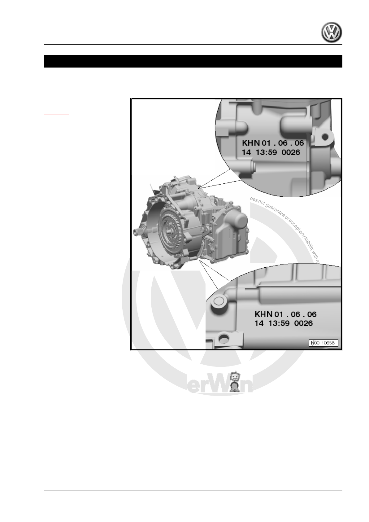
1 Gearbox identification
KHN - Gearbox code letters
⇒ page 2
01.06.06 - Production date:
1 June 2006
14 - Factory code
14 15 - Time
0026 - Serial number
7-speed dual clutch gearbox 0AM - Edition 07.2010
1. Gearbox identification 1
Page 6
P
r
o
t
e
c
t
e
d
b
y
c
o
p
y
r
i
g
h
t
.
C
o
p
y
i
n
g
f
o
r
p
r
i
v
a
t
e
o
r
c
o
m
m
e
r
c
i
a
l
p
u
r
p
o
s
e
s
,
i
n
p
a
r
t
o
r
i
n
w
h
o
l
e
,
i
s
n
o
t
p
e
r
m
i
t
t
e
d
u
n
l
e
s
s
a
u
t
h
o
r
i
s
e
d
b
y
V
o
l
k
s
w
a
g
e
n
A
G
.
V
o
l
k
s
w
a
g
e
n
A
G
d
o
e
s
n
o
t
g
u
a
r
a
n
t
e
e
o
r
a
c
c
e
p
t
a
n
y
l
i
a
b
i
l
i
t
y
w
i
t
h
r
e
s
p
e
c
t
t
o
t
h
e
c
o
r
r
e
c
t
n
e
s
s
o
f
i
n
f
o
r
m
a
t
i
o
n
i
n
t
h
i
s
d
o
c
u
m
e
n
t
.
C
o
p
y
r
i
g
h
t
b
y
V
o
l
k
s
w
a
g
e
n
A
G
.
Golf Variant 2007 ➤ , Golf Variant 2010 ➤ , Jetta 2005 ➤ , Jetta 2011 ➤
7-speed dual clutch gearbox 0AM - Edition 07.2010
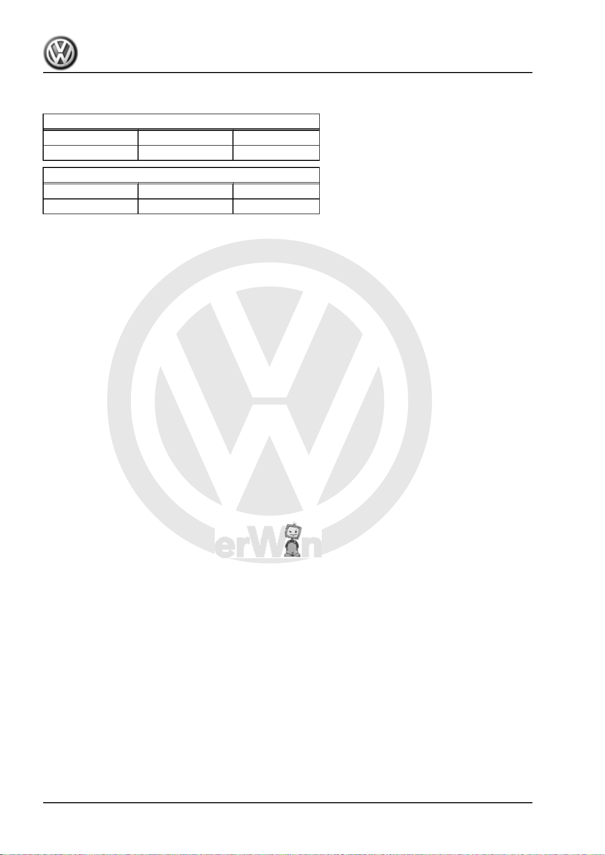
2 Code, engine allocation
Allocation: gearbox codes for petrol engines
KHN, LKG, LKM KUT, LPL LSU
1.4 l/90 kW TSFI 1.4 l/118 kW TSI 1.6 l/75 kW MPI
Allocation: gearbox codes for diesel engines
KHM, LKL, LKF LQN, LST
1.9 l/77 kW TDI PD 1.6 l/77 kW TDI CR
2 Rep. Gr.00 - Technical data
Page 7
P
r
o
t
e
c
t
e
d
b
y
c
o
p
y
r
i
g
h
t
.
C
o
p
y
i
n
g
f
o
r
p
r
i
v
a
t
e
o
r
c
o
m
m
e
r
c
i
a
l
p
u
r
p
o
s
e
s
,
i
n
p
a
r
t
o
r
i
n
w
h
o
l
e
,
i
s
n
o
t
p
e
r
m
i
t
t
e
d
u
n
l
e
s
s
a
u
t
h
o
r
i
s
e
d
b
y
V
o
l
k
s
w
a
g
e
n
A
G
.
V
o
l
k
s
w
a
g
e
n
A
G
d
o
e
s
n
o
t
g
u
a
r
a
n
t
e
e
o
r
a
c
c
e
p
t
a
n
y
l
i
a
b
i
l
i
t
y
w
i
t
h
r
e
s
p
e
c
t
t
o
t
h
e
c
o
r
r
e
c
t
n
e
s
s
o
f
i
n
f
o
r
m
a
t
i
o
n
i
n
t
h
i
s
d
o
c
u
m
e
n
t
.
C
o
p
y
r
i
g
h
t
b
y
V
o
l
k
s
w
a
g
e
n
A
G
.
Golf Variant 2007 ➤ , Golf Variant 2010 ➤ , Jetta 2005 ➤ , Jetta 2011 ➤
7-speed dual clutch gearbox 0AM - Edition 07.2010
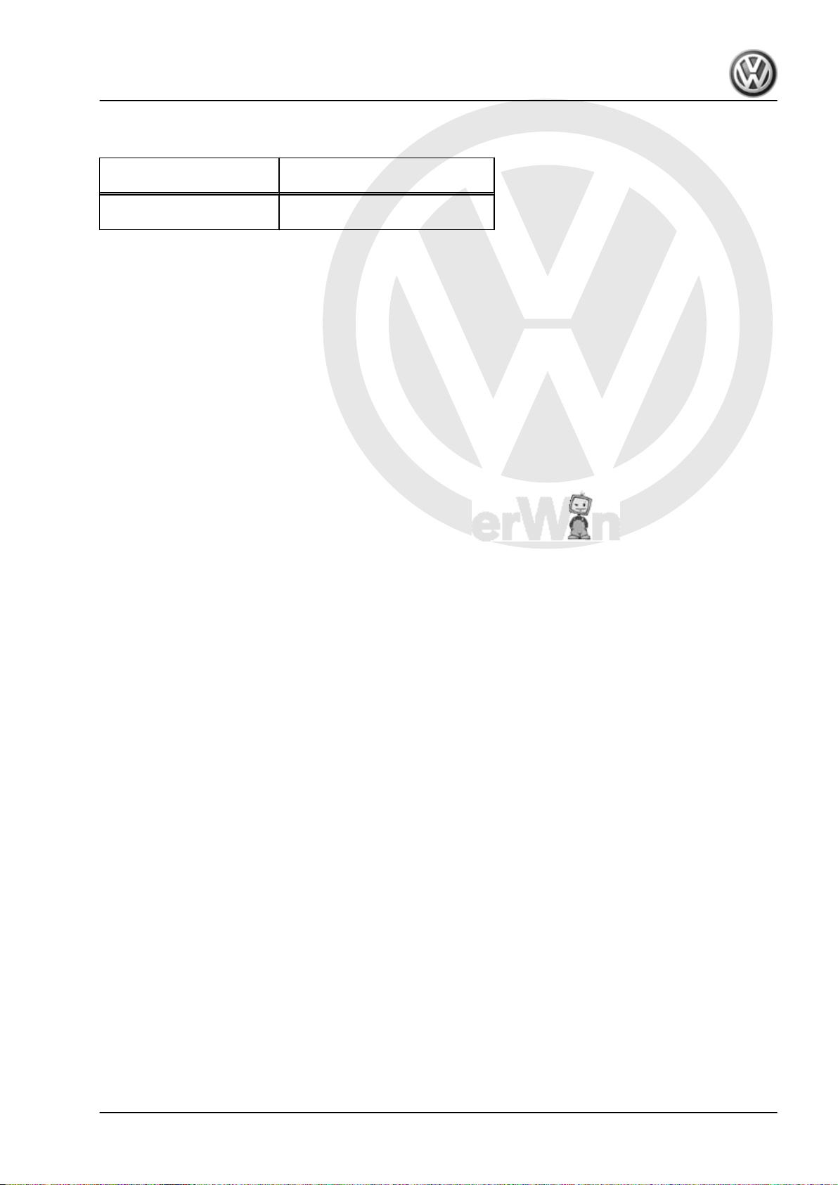
3 Capacities
Dual clutch gearbox 0AM Mechatronic unit for dual clutch
1.7 l gear oil -G 052 171- 1 l central hydraulic oil and power
Further information in the part number designates the container
size.
gearbox -J743-
steering oil -G 004 000-
3. Capacities 3
Page 8
P
r
o
t
e
c
t
e
d
b
y
c
o
p
y
r
i
g
h
t
.
C
o
p
y
i
n
g
f
o
r
p
r
i
v
a
t
e
o
r
c
o
m
m
e
r
c
i
a
l
p
u
r
p
o
s
e
s
,
i
n
p
a
r
t
o
r
i
n
w
h
o
l
e
,
i
s
n
o
t
p
e
r
m
i
t
t
e
d
u
n
l
e
s
s
a
u
t
h
o
r
i
s
e
d
b
y
V
o
l
k
s
w
a
g
e
n
A
G
.
V
o
l
k
s
w
a
g
e
n
A
G
d
o
e
s
n
o
t
g
u
a
r
a
n
t
e
e
o
r
a
c
c
e
p
t
a
n
y
l
i
a
b
i
l
i
t
y
w
i
t
h
r
e
s
p
e
c
t
t
o
t
h
e
c
o
r
r
e
c
t
n
e
s
s
o
f
i
n
f
o
r
m
a
t
i
o
n
i
n
t
h
i
s
d
o
c
u
m
e
n
t
.
C
o
p
y
r
i
g
h
t
b
y
V
o
l
k
s
w
a
g
e
n
A
G
.
Golf Variant 2007 ➤ , Golf Variant 2010 ➤ , Jetta 2005 ➤ , Jetta 2011 ➤
7-speed dual clutch gearbox 0AM - Edition 07.2010
4 General repair notes
4.1 Tools
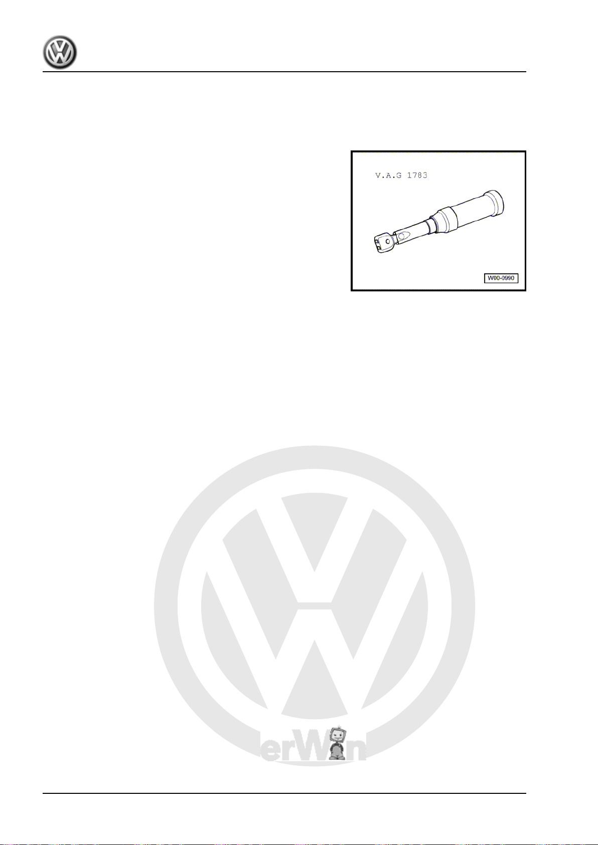
Uncertainty often occurs with smaller bolts having low tightening
forces. Torque wrench 2...10 Nm -V.A.G 1783- can be used with
these bolts.
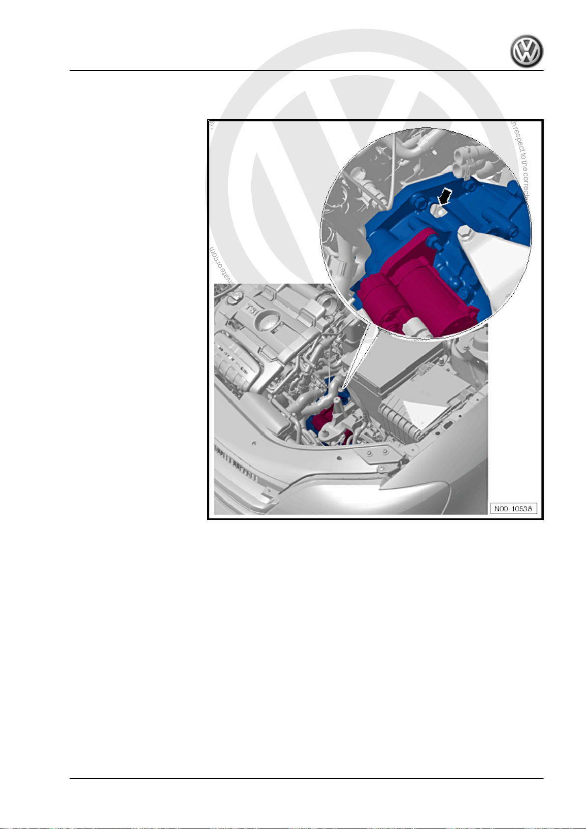
4.2 Gearbox
The gearbox has a hole in the housing.
4 Rep. Gr.00 - Technical data
Page 9
P
r
o
t
e
c
t
e
d
b
y
c
o
p
y
r
i
g
h
t
.
C
o
p
y
i
n
g
f
o
r
p
r
i
v
a
t
e
o
r
c
o
m
m
e
r
c
i
a
l
p
u
r
p
o
s
e
s
,
i
n
p
a
r
t
o
r
i
n
w
h
o
l
e
,
i
s
n
o
t
p
e
r
m
i
t
t
e
d
u
n
l
e
s
s
a
u
t
h
o
r
i
s
e
d
b
y
V
o
l
k
s
w
a
g
e
n
A
G
.
V
o
l
k
s
w
a
g
e
n
A
G
d
o
e
s
n
o
t
g
u
a
r
a
n
t
e
e
o
r
a
c
c
e
p
t
a
n
y
l
i
a
b
i
l
i
t
y
w
i
t
h
r
e
s
p
e
c
t
t
o
t
h
e
c
o
r
r
e
c
t
n
e
s
s
o
f
i
n
f
o
r
m
a
t
i
o
n
i
n
t
h
i
s
d
o
c
u
m
e
n
t
.
C
o
p
y
r
i
g
h
t
b
y
V
o
l
k
s
w
a
g
e
n
A
G
.
Golf Variant 2007 ➤ , Golf Variant 2010 ➤ , Jetta 2005 ➤ , Jetta 2011 ➤
– Make sure no small parts drop into this hole during installation
work.
7-speed dual clutch gearbox 0AM - Edition 07.2010
– Cover the hole with a cloth before installation work.
Make sure that no dirt can enter an “open” gearbox.
♦ If gearbox covers have been unbolted or gearbox has no fluid,
do not run engine. Do not tow vehicle.
♦ First thoroughly clean connecting points and surrounding
areas and then loosen bolts.
♦ During installation, ensure that the dowel sleeves between the
engine and gearbox are correctly located.
♦ Place removed parts on a clean surface. Cover parts to pre‐
vent soiling. Use plastic sheeting and paper. Use lint-free
cloths only!
♦ Install only clean parts; do not remove Genuine parts from
packaging until immediately before installing.
♦ If repair work cannot be performed immediately, cover opened
parts carefully.
4. General repair notes 5
Page 10
P
r
o
t
e
c
t
e
d
b
y
c
o
p
y
r
i
g
h
t
.
C
o
p
y
i
n
g
f
o
r
p
r
i
v
a
t
e
o
r
c
o
m
m
e
r
c
i
a
l
p
u
r
p
o
s
e
s
,
i
n
p
a
r
t
o
r
i
n
w
h
o
l
e
,
i
s
n
o
t
p
e
r
m
i
t
t
e
d
u
n
l
e
s
s
a
u
t
h
o
r
i
s
e
d
b
y
V
o
l
k
s
w
a
g
e
n
A
G
.
V
o
l
k
s
w
a
g
e
n
A
G
d
o
e
s
n
o
t
g
u
a
r
a
n
t
e
e
o
r
a
c
c
e
p
t
a
n
y
l
i
a
b
i
l
i
t
y
w
i
t
h
r
e
s
p
e
c
t
t
o
t
h
e
c
o
r
r
e
c
t
n
e
s
s
o
f
i
n
f
o
r
m
a
t
i
o
n
i
n
t
h
i
s
d
o
c
u
m
e
n
t
.
C
o
p
y
r
i
g
h
t
b
y
V
o
l
k
s
w
a
g
e
n
A
G
.
Golf Variant 2007 ➤ , Golf Variant 2010 ➤ , Jetta 2005 ➤ , Jetta 2011 ➤
7-speed dual clutch gearbox 0AM - Edition 07.2010
In some vehicles, a cover is fitted over the engaging levers.
The cover prevents dirt getting in.
Torque setting: 8 Nm
4.3 Oil
The “0AM” gearbox has two oil circuits. One oil fill is for gears,
shafts and differential. A 2nd oil fill is for mechatronic unit for dual
clutch gearbox -J743- .
Both oils are Genuine parts ⇒ page 3 .
Do not mix “additives” in oil.
Oil which has been drained out cannot be added again.
Caution
Use caution when handling oil. Dispose of used oil properly.
One drop of oil will contaminate 600 litres of water.
4.4 Working with vehicle diagnostic testers
• Only work with vehicle diagnostic testers from Volkswagen.
♦ Vehicle diagnosis and service information system -VAS 5052
A-
♦ Vehicle diagnosis, testing and information system -VAS
5051B-
♦ Vehicle diagnostic tester -VAS 5053Various functions are available in the operating modes guided
functions and guided fault finding . The 3 most important
functions are:
♦ Adapting installation information
♦ Reading measured values for mandatory reporting
♦ Initiating basic adjustment
4.4.1 Adapting installation information
The mechatronic unit detects other control units in the vehicle by
means of signals on the data bus. Pressing the Adapt instal-
lation information lock button instructs the mechatronic unit
to forget all communication partners.
6 Rep. Gr.00 - Technical data
Page 11
P
r
o
t
e
c
t
e
d
b
y
c
o
p
y
r
i
g
h
t
.
C
o
p
y
i
n
g
f
o
r
p
r
i
v
a
t
e
o
r
c
o
m
m
e
r
c
i
a
l
p
u
r
p
o
s
e
s
,
i
n
p
a
r
t
o
r
i
n
w
h
o
l
e
,
i
s
n
o
t
p
e
r
m
i
t
t
e
d
u
n
l
e
s
s
a
u
t
h
o
r
i
s
e
d
b
y
V
o
l
k
s
w
a
g
e
n
A
G
.
V
o
l
k
s
w
a
g
e
n
A
G
d
o
e
s
n
o
t
g
u
a
r
a
n
t
e
e
o
r
a
c
c
e
p
t
a
n
y
l
i
a
b
i
l
i
t
y
w
i
t
h
r
e
s
p
e
c
t
t
o
t
h
e
c
o
r
r
e
c
t
n
e
s
s
o
f
i
n
f
o
r
m
a
t
i
o
n
i
n
t
h
i
s
d
o
c
u
m
e
n
t
.
C
o
p
y
r
i
g
h
t
b
y
V
o
l
k
s
w
a
g
e
n
A
G
.
Golf Variant 2007 ➤ , Golf Variant 2010 ➤ , Jetta 2005 ➤ , Jetta 2011 ➤
All “active partners” are detected once again the next time the
ignition system is switched on.
You cannot “generate” any faults using this function. Please al‐
ways perform the Adapt installation information function
after the following activities:
♦ After a selector lever has been installed.
♦ After another control unit has been installed, e.g. engine, ABS
or gateway.
♦ After work on the steering wheel paddle.
4.4.2 Reading measured values for mandato‐
You must read these measured values before contacting your
ry reporting
Technical Service Center or your importer.
Save the measured values in the diagnosis log so that all neces‐
sary gearbox data will be available for fault analysis.
4.4.3 Initiating basic adjustment
This teaches important settings into the mechatronic unit. Even
important adjustments are taught in again, or reset to program‐
med points. These include, for example, the synchronisation
points and “reference points” for the engaging lever and gear ac‐
tuator.
– Press the button DSG Mechatronic -J743- performing
7-speed dual clutch gearbox 0AM - Edition 07.2010
basic measurement only:
♦ if you are prompted to do so in “guided fault finding”
♦ after you have processed a fault entry
♦ after you have installed another gearbox
♦ after you have installed a clutch
♦ or after you have installed a mechatronic unit
4. General repair notes 7
Page 12
P
r
o
t
e
c
t
e
d
b
y
c
o
p
y
r
i
g
h
t
.
C
o
p
y
i
n
g
f
o
r
p
r
i
v
a
t
e
o
r
c
o
m
m
e
r
c
i
a
l
p
u
r
p
o
s
e
s
,
i
n
p
a
r
t
o
r
i
n
w
h
o
l
e
,
i
s
n
o
t
p
e
r
m
i
t
t
e
d
u
n
l
e
s
s
a
u
t
h
o
r
i
s
e
d
b
y
V
o
l
k
s
w
a
g
e
n
A
G
.
V
o
l
k
s
w
a
g
e
n
A
G
d
o
e
s
n
o
t
g
u
a
r
a
n
t
e
e
o
r
a
c
c
e
p
t
a
n
y
l
i
a
b
i
l
i
t
y
w
i
t
h
r
e
s
p
e
c
t
t
o
t
h
e
c
o
r
r
e
c
t
n
e
s
s
o
f
i
n
f
o
r
m
a
t
i
o
n
i
n
t
h
i
s
d
o
c
u
m
e
n
t
.
C
o
p
y
r
i
g
h
t
b
y
V
o
l
k
s
w
a
g
e
n
A
G
.
Golf Variant 2007 ➤ , Golf Variant 2010 ➤ , Jetta 2005 ➤ , Jetta 2011 ➤
7-speed dual clutch gearbox 0AM - Edition 07.2010
30 – Clutch
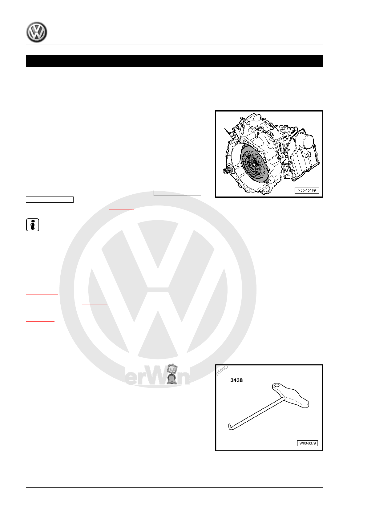
1 Removing and installing the dual
clutch
Brief description
The clutch is installed “upwards” with the gearbox removed. The
mechatronic unit remains on the gearbox.
If one new clutch is installed, the positions of the engagement
bearings for “K 1” and “K 2” must be found and set. Then the clutch
is pressed onto the input shaft.
When installing a clutch, “most” mechanics push the clutch onto
the input shaft up to the stop. This is not the optimum position for
the clutch!
For this reason, pull the clutch slightly “upwards” against the re‐
taining ring after it has been installed.
After the gearbox has been installed, you must initiate a ba-
sic adjustment using the ⇒ Vehicle diagnosis, testing and
information system VAS 5051 ⇒ page 7 .
Note
The clutch is self-adjusting. Shocks can have an effect on this
adjusting device. Therefore, please do not drop the clutch. Do not
left the clutch drop into the gearbox either when installing the
clutch. Even if the mechatronic unit has been removed, “pulling
out” the assembly lever -T10407- under the engaging levers can
have a negative effect on the adjusting device.
Transporting gearbox and securing to assembly stand
⇒ page 111 .
Remove dual clutch ⇒ page 8 .
Adjust the position of the engagement bearings “K 1 and K 2”
⇒ page 12 .
Install dual clutch ⇒ page 22 .
1.1 Removing dual clutch
Special tools and workshop equipment required
♦ Hook -3438-
8 Rep. Gr.30 - Clutch
Page 13
P
r
o
t
e
c
t
e
d
b
y
c
o
p
y
r
i
g
h
t
.
C
o
p
y
i
n
g
f
o
r
p
r
i
v
a
t
e
o
r
c
o
m
m
e
r
c
i
a
l
p
u
r
p
o
s
e
s
,
i
n
p
a
r
t
o
r
i
n
w
h
o
l
e
,
i
s
n
o
t
p
e
r
m
i
t
t
e
d
u
n
l
e
s
s
a
u
t
h
o
r
i
s
e
d
b
y
V
o
l
k
s
w
a
g
e
n
A
G
.
V
o
l
k
s
w
a
g
e
n
A
G
d
o
e
s
n
o
t
g
u
a
r
a
n
t
e
e
o
r
a
c
c
e
p
t
a
n
y
l
i
a
b
i
l
i
t
y
w
i
t
h
r
e
s
p
e
c
t
t
o
t
h
e
c
o
r
r
e
c
t
n
e
s
s
o
f
i
n
f
o
r
m
a
t
i
o
n
i
n
t
h
i
s
d
o
c
u
m
e
n
t
.
C
o
p
y
r
i
g
h
t
b
y
V
o
l
k
s
w
a
g
e
n
A
G
.
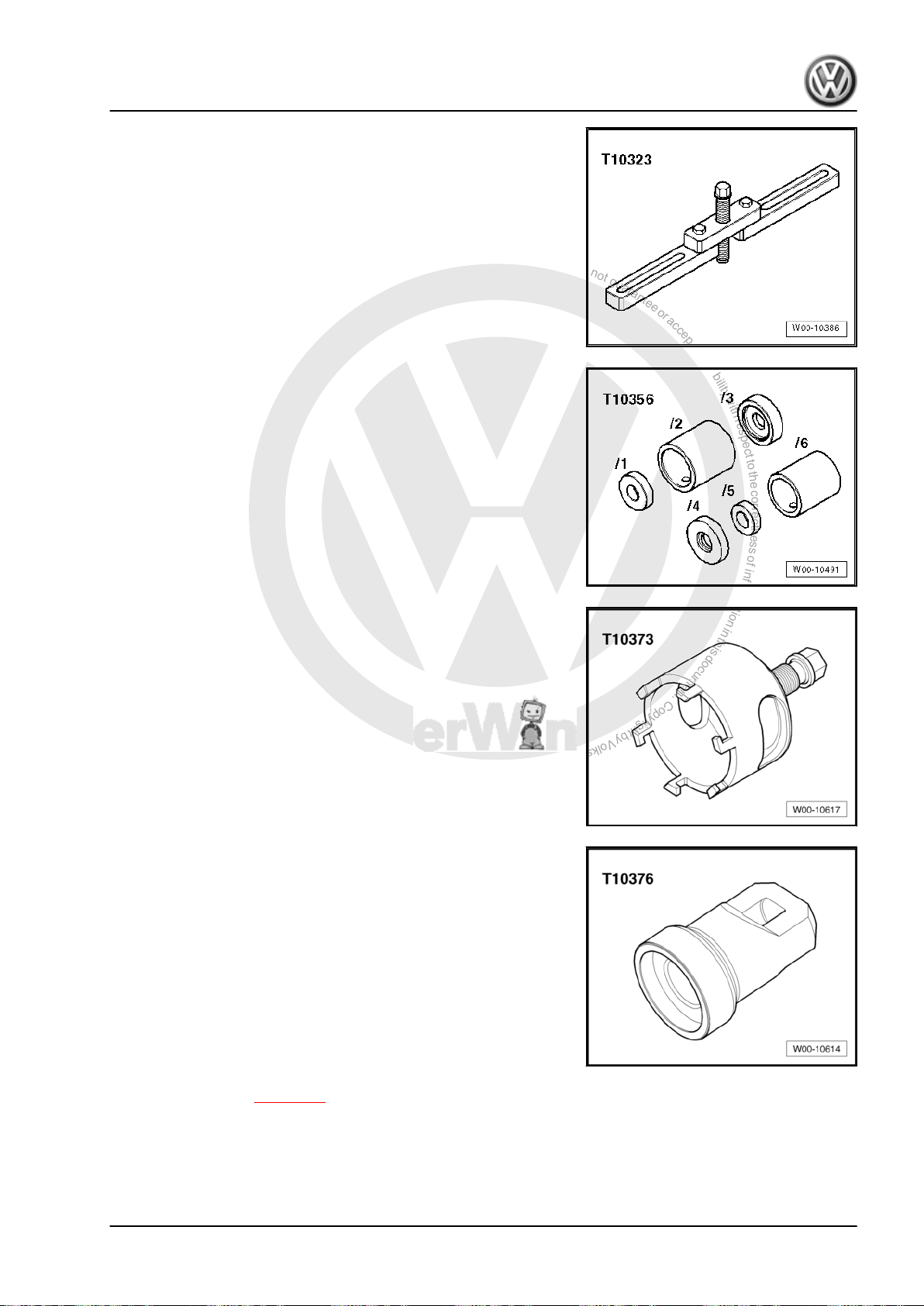
♦ Support device -T10323-
♦ Assembly tool -T10356-
♦ Puller -T10373-
Golf Variant 2007 ➤ , Golf Variant 2010 ➤ , Jetta 2005 ➤ , Jetta 2011 ➤
7-speed dual clutch gearbox 0AM - Edition 07.2010
♦ Thrust piece -T10376-
– Remove gearbox ⇒ page 73 .
1. Removing and installing the dual clutch 9
Page 14
P
r
o
t
e
c
t
e
d
b
y
c
o
p
y
r
i
g
h
t
.
C
o
p
y
i
n
g
f
o
r
p
r
i
v
a
t
e
o
r
c
o
m
m
e
r
c
i
a
l
p
u
r
p
o
s
e
s
,
i
n
p
a
r
t
o
r
i
n
w
h
o
l
e
,
i
s
n
o
t
p
e
r
m
i
t
t
e
d
u
n
l
e
s
s
a
u
t
h
o
r
i
s
e
d
b
y
V
o
l
k
s
w
a
g
e
n
A
G
.
V
o
l
k
s
w
a
g
e
n
A
G
d
o
e
s
n
o
t
g
u
a
r
a
n
t
e
e
o
r
a
c
c
e
p
t
a
n
y
l
i
a
b
i
l
i
t
y
w
i
t
h
r
e
s
p
e
c
t
t
o
t
h
e
c
o
r
r
e
c
t
n
e
s
s
o
f
i
n
f
o
r
m
a
t
i
o
n
i
n
t
h
i
s
d
o
c
u
m
e
n
t
.
C
o
p
y
r
i
g
h
t
b
y
V
o
l
k
s
w
a
g
e
n
A
G
.
Golf Variant 2007 ➤ , Golf Variant 2010 ➤ , Jetta 2005 ➤ , Jetta 2011 ➤
7-speed dual clutch gearbox 0AM - Edition 07.2010
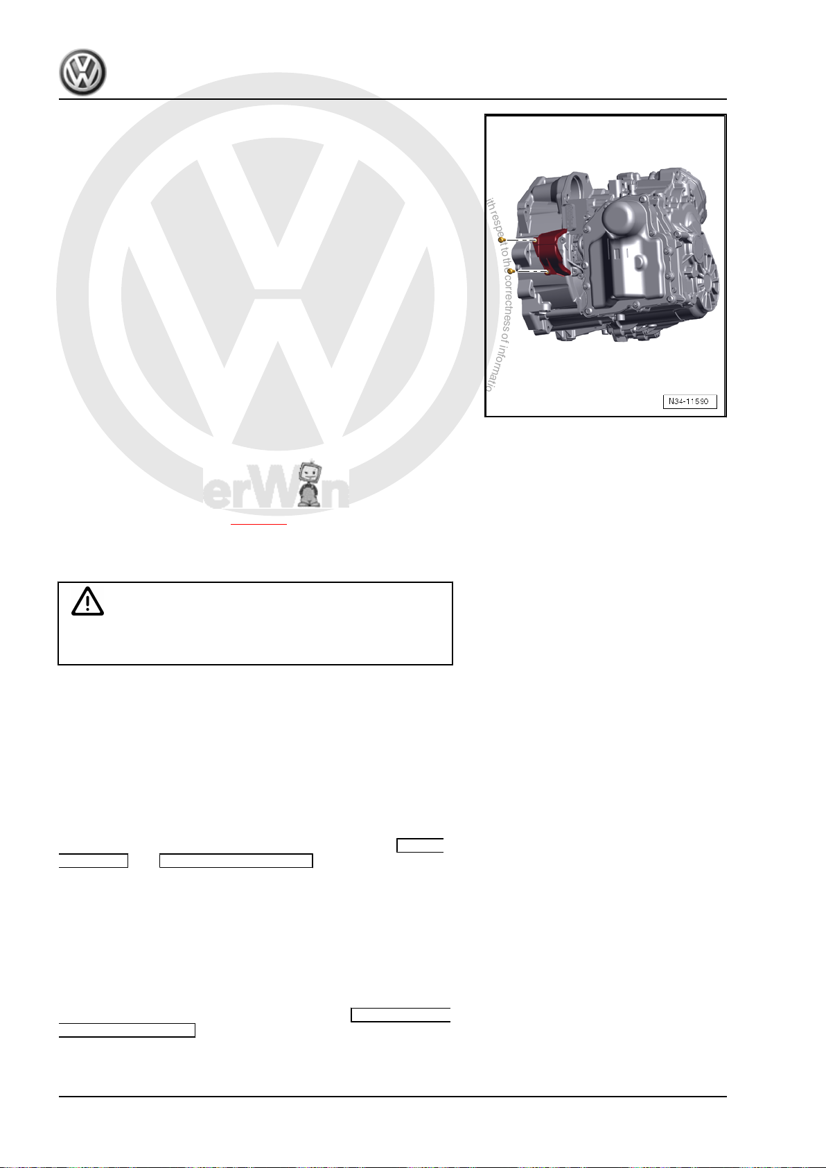
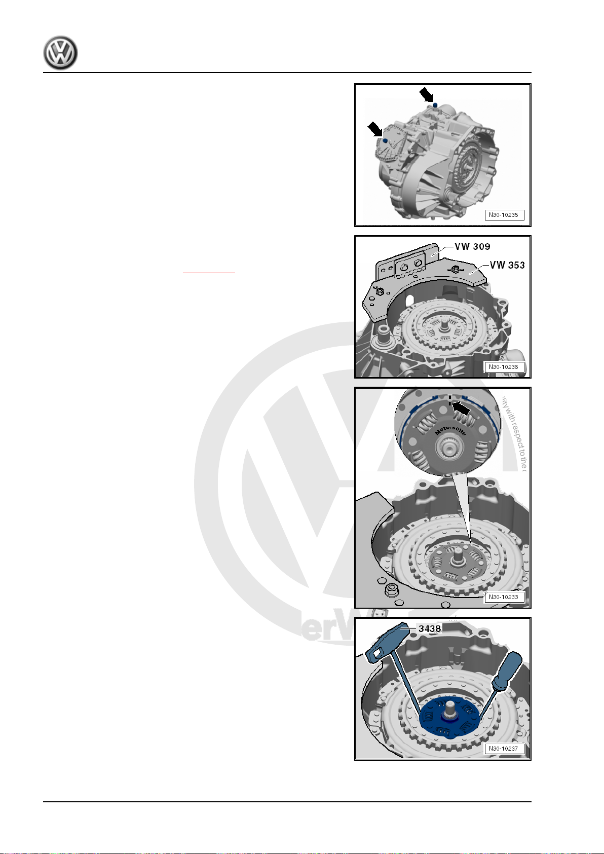
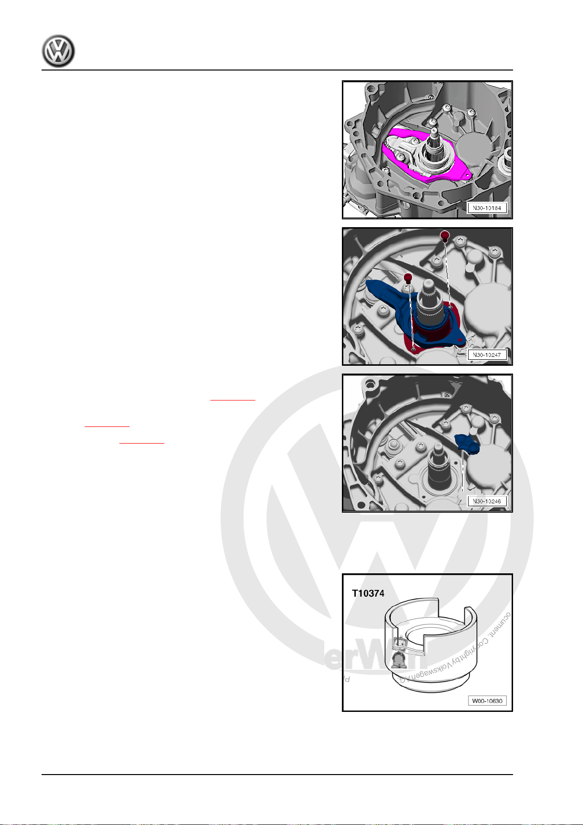
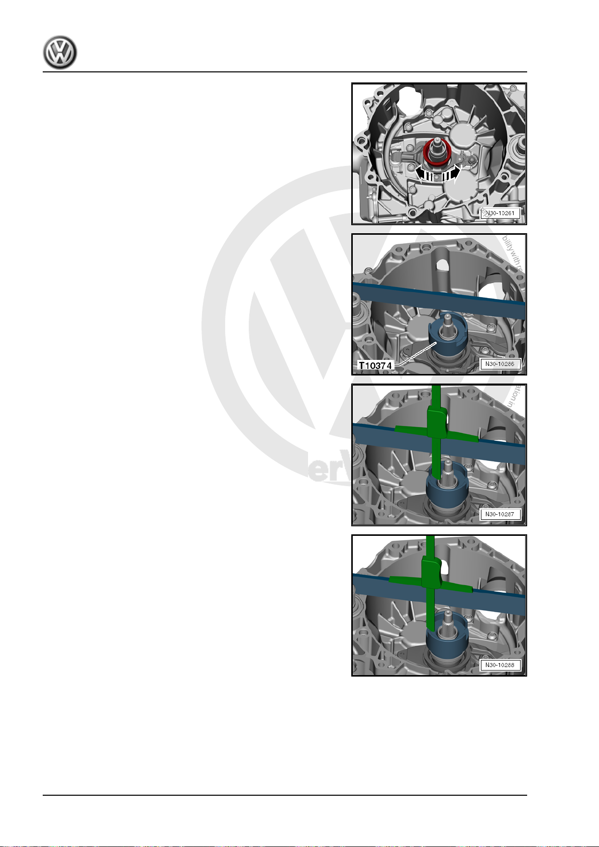
– Pull off both breather caps -arrows- and close using suitable
plugs to achieve an oil-tight seal.
Turn gearbox with clutch upwards.
For information about how to transport the gearbox securely and
attach it to the assembly stand ⇒ page 111 .
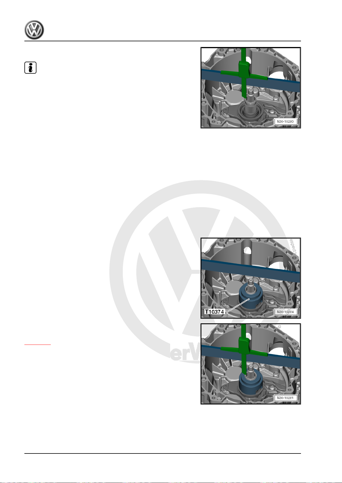
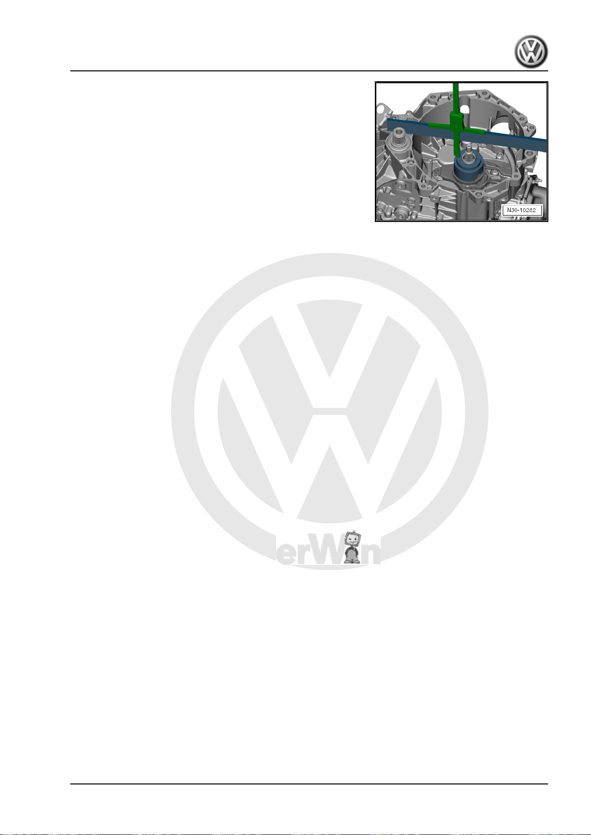
– Remove retaining ring of hub -arrow-.
– Remove hub with hook -3438- and a screwdriver.
10 Rep. Gr.30 - Clutch
Page 15
P
r
o
t
e
c
t
e
d
b
y
c
o
p
y
r
i
g
h
t
.
C
o
p
y
i
n
g
f
o
r
p
r
i
v
a
t
e
o
r
c
o
m
m
e
r
c
i
a
l
p
u
r
p
o
s
e
s
,
i
n
p
a
r
t
o
r
i
n
w
h
o
l
e
,
i
s
n
o
t
p
e
r
m
i
t
t
e
d
u
n
l
e
s
s
a
u
t
h
o
r
i
s
e
d
b
y
V
o
l
k
s
w
a
g
e
n
A
G
.
V
o
l
k
s
w
a
g
e
n
A
G
d
o
e
s
n
o
t
g
u
a
r
a
n
t
e
e
o
r
a
c
c
e
p
t
a
n
y
l
i
a
b
i
l
i
t
y
w
i
t
h
r
e
s
p
e
c
t
t
o
t
h
e
c
o
r
r
e
c
t
n
e
s
s
o
f
i
n
f
o
r
m
a
t
i
o
n
i
n
t
h
i
s
d
o
c
u
m
e
n
t
.
C
o
p
y
r
i
g
h
t
b
y
V
o
l
k
s
w
a
g
e
n
A
G
.
Golf Variant 2007 ➤ , Golf Variant 2010 ➤ , Jetta 2005 ➤ , Jetta 2011 ➤
7-speed dual clutch gearbox 0AM - Edition 07.2010
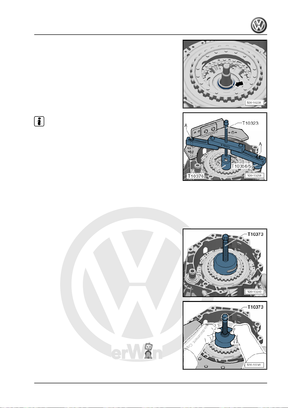
– Remove retaining ring of clutch -arrow-.
Note
♦
It is possible that the retaining ring is seated very tightly. The
cause may be that the clutch is pressing so hard against the
retaining ring that the ring is stuck.
♦
If you cannot get the ring out of the groove, press the clutch
down slightly. Never strike the clutch or shaft with a hammer!
Set up the tools that are shown in this illustration.
♦
Support bracket -T10323- fits on all 0AM gearboxes.
♦
Make sure that you place support bracket -T10323- in parallel
to the gearbox flange.
♦
Secure engine support with bolts -A-, as required with nuts.
♦
Always renew retaining ring.
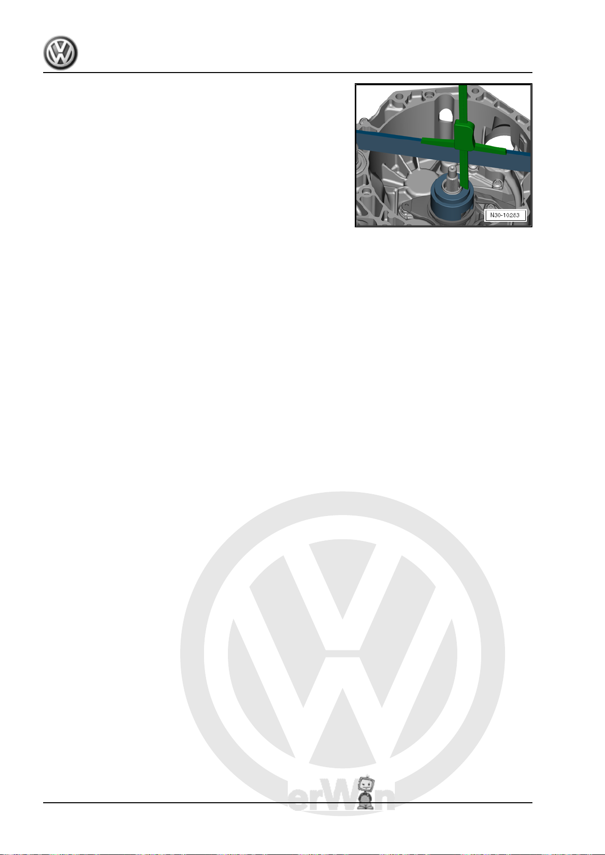
Clutch should only be pressed down slightly. Often, it is sufficient
to rotate spindle against thrust piece -T10376- without pressing.
This will “release” retaining ring.
– Pull off clutch.
– Remove clutch together with puller -T10373- .
1. Removing and installing the dual clutch 11
Page 16
P
r
o
t
e
c
t
e
d
b
y
c
o
p
y
r
i
g
h
t
.
C
o
p
y
i
n
g
f
o
r
p
r
i
v
a
t
e
o
r
c
o
m
m
e
r
c
i
a
l
p
u
r
p
o
s
e
s
,
i
n
p
a
r
t
o
r
i
n
w
h
o
l
e
,
i
s
n
o
t
p
e
r
m
i
t
t
e
d
u
n
l
e
s
s
a
u
t
h
o
r
i
s
e
d
b
y
V
o
l
k
s
w
a
g
e
n
A
G
.
V
o
l
k
s
w
a
g
e
n
A
G
d
o
e
s
n
o
t
g
u
a
r
a
n
t
e
e
o
r
a
c
c
e
p
t
a
n
y
l
i
a
b
i
l
i
t
y
w
i
t
h
r
e
s
p
e
c
t
t
o
t
h
e
c
o
r
r
e
c
t
n
e
s
s
o
f
i
n
f
o
r
m
a
t
i
o
n
i
n
t
h
i
s
d
o
c
u
m
e
n
t
.
C
o
p
y
r
i
g
h
t
b
y
V
o
l
k
s
w
a
g
e
n
A
G
.
Golf Variant 2007 ➤ , Golf Variant 2010 ➤ , Jetta 2005 ➤ , Jetta 2011 ➤
7-speed dual clutch gearbox 0AM - Edition 07.2010
– Remove small engagement bearing.
– Remove large engaging lever.
– Remove bolts and remove small engaging lever.
– Remove retainer for engaging lever.
Before installing clutch, please refer to ⇒ page 12 to see wheth‐
er “clutch needs adjusting during assembly or not.”
Adjusting ⇒ page 12 .
Install dual clutch ⇒ page 22 .
1.2 Adjusting position of engagement bear‐
ings “K 1 and K 2”
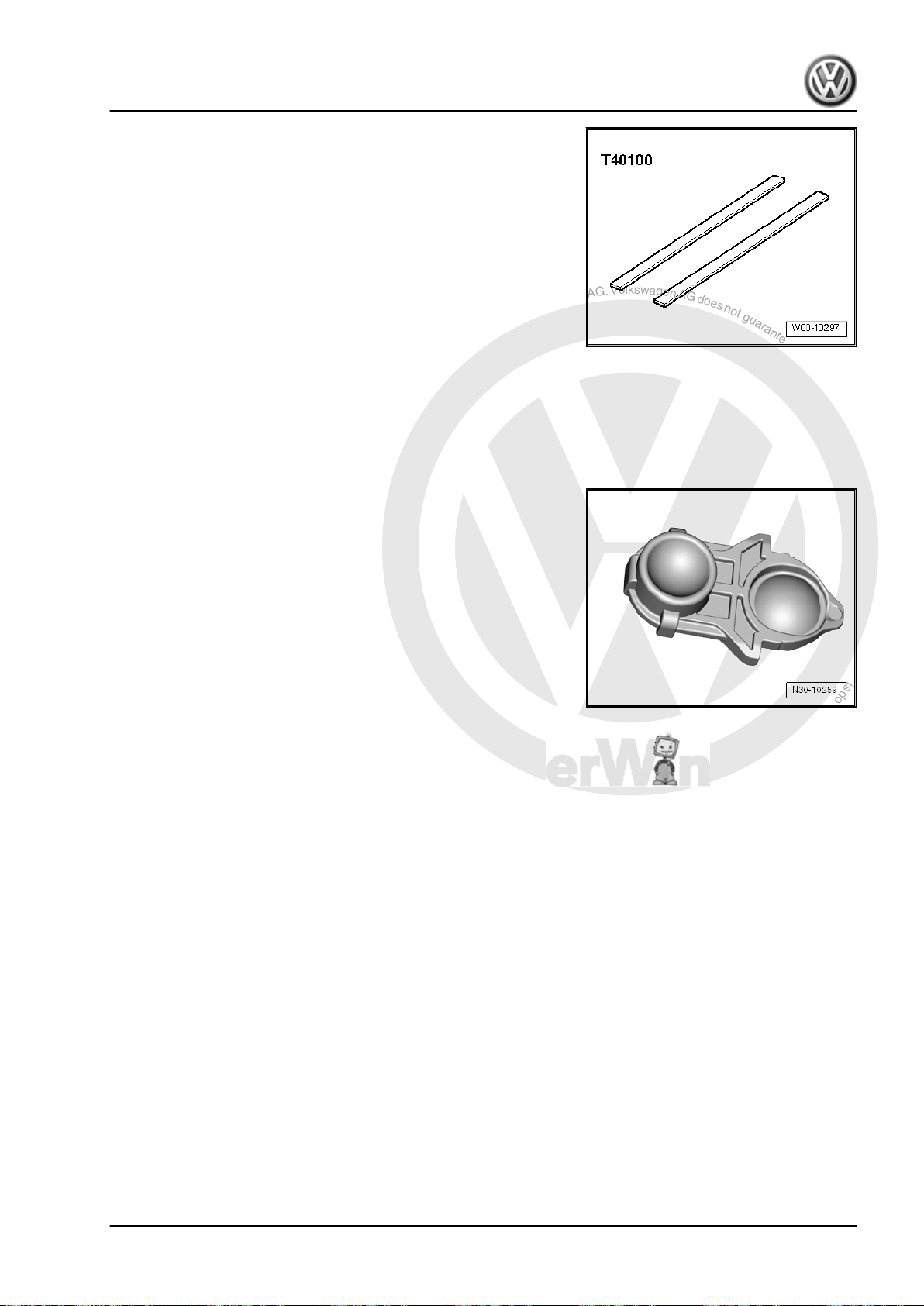
Special tools and workshop equipment required
♦ Gauge block -T10374-
12 Rep. Gr.30 - Clutch
Page 17
P
r
o
t
e
c
t
e
d
b
y
c
o
p
y
r
i
g
h
t
.
C
o
p
y
i
n
g
f
o
r
p
r
i
v
a
t
e
o
r
c
o
m
m
e
r
c
i
a
l
p
u
r
p
o
s
e
s
,
i
n
p
a
r
t
o
r
i
n
w
h
o
l
e
,
i
s
n
o
t
p
e
r
m
i
t
t
e
d
u
n
l
e
s
s
a
u
t
h
o
r
i
s
e
d
b
y
V
o
l
k
s
w
a
g
e
n
A
G
.
V
o
l
k
s
w
a
g
e
n
A
G
d
o
e
s
n
o
t
g
u
a
r
a
n
t
e
e
o
r
a
c
c
e
p
t
a
n
y
l
i
a
b
i
l
i
t
y
w
i
t
h
r
e
s
p
e
c
t
t
o
t
h
e
c
o
r
r
e
c
t
n
e
s
s
o
f
i
n
f
o
r
m
a
t
i
o
n
i
n
t
h
i
s
d
o
c
u
m
e
n
t
.
C
o
p
y
r
i
g
h
t
b
y
V
o
l
k
s
w
a
g
e
n
A
G
.
Golf Variant 2007 ➤ , Golf Variant 2010 ➤ , Jetta 2005 ➤ , Jetta 2011 ➤
7-speed dual clutch gearbox 0AM - Edition 07.2010
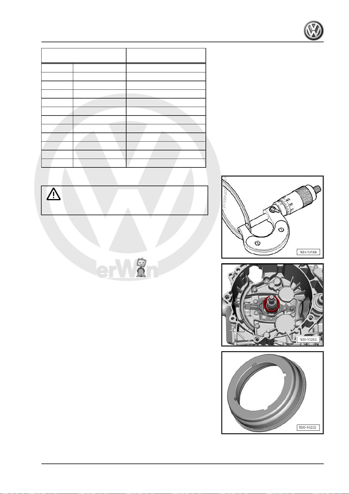
♦ Ruler -T40100-
♦ Digital depth gauge e.g. -VAS 6594-
♦ Adhesive -AMV 195 KD1 01-
♦ Micrometer caliper
Position of engagement bearings must be set after clutch and its
actuators have been renewed.
♦ Retainer also belongs to actuator.
There is no need to adjust anything if all the named parts have
only been removed and reinstalled.
Conditions:
• Only use tools in perfect condition.
• Contact surface of “gearbox on engine” must be free from “ir‐
regularities”. This guarantees straight edge makes good con‐
tact.
• Mechatronic unit is installed.
Perform the following steps:
Position of engagement bearings is comparable with clutch play
of a manual gearbox. In this 0AM dual clutch gearbox, there are
tolerances in engagement system of gearbox and in gearbox it‐
self. There are also tolerances within the dual clutch. These
tolerances must be considered separately when adjusting.
In the following procedure, you are first shown how to measure
all necessary dimensions “on gearbox”, in order to determine
what is the appropriate shim. Tolerances on gearbox and toler‐
ances in clutch determine thickness of shim.
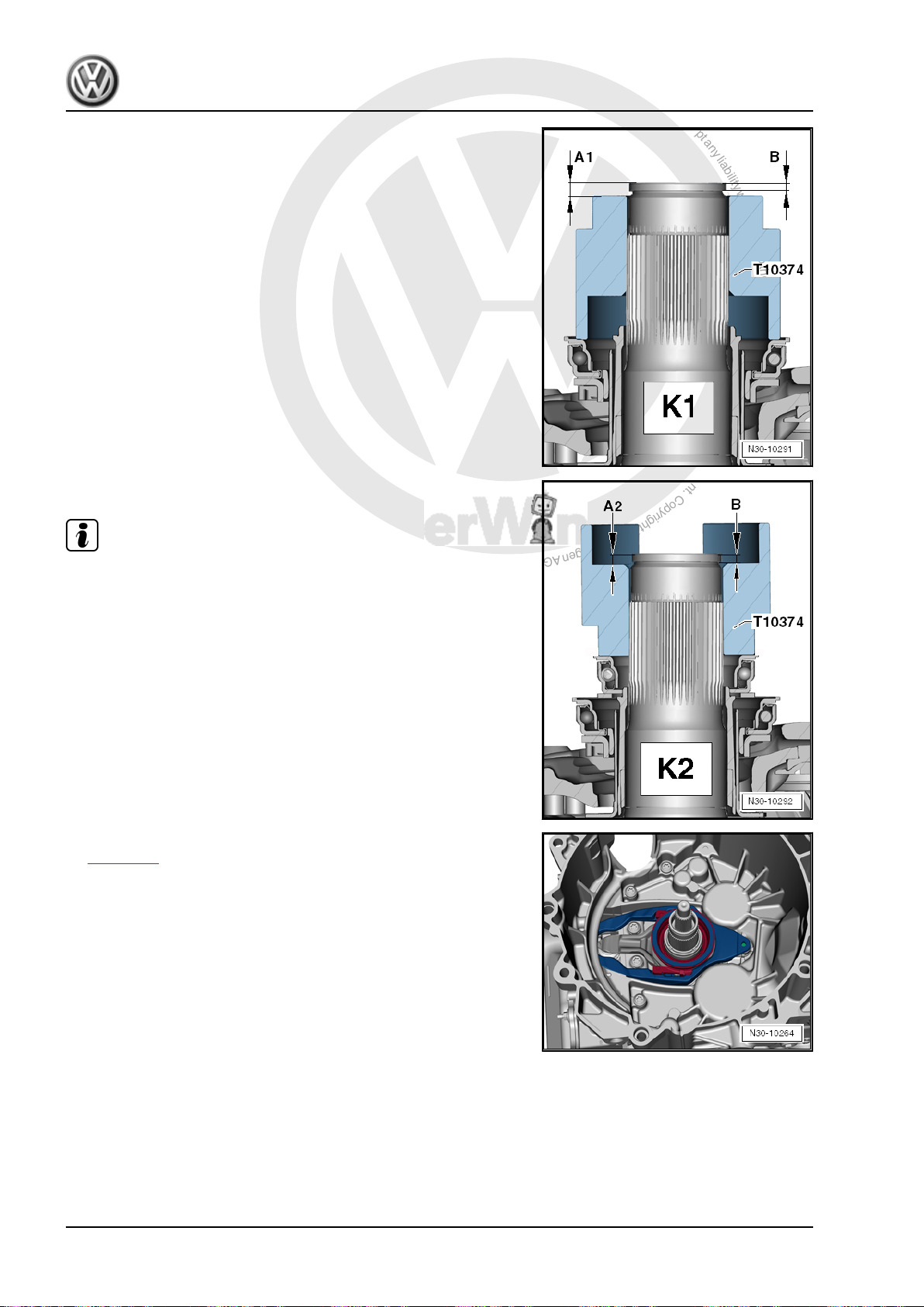
First find a dimension “B”. This dimensions is required for both
clutches “K 1” and “K 2”.
Then find a dimension “A” for each clutch. The following 2 illus‐
trations show where to measure these dimensions.
1. Removing and installing the dual clutch 13
Page 18
P
r
o
t
e
c
t
e
d
b
y
c
o
p
y
r
i
g
h
t
.
C
o
p
y
i
n
g
f
o
r
p
r
i
v
a
t
e
o
r
c
o
m
m
e
r
c
i
a
l
p
u
r
p
o
s
e
s
,
i
n
p
a
r
t
o
r
i
n
w
h
o
l
e
,
i
s
n
o
t
p
e
r
m
i
t
t
e
d
u
n
l
e
s
s
a
u
t
h
o
r
i
s
e
d
b
y
V
o
l
k
s
w
a
g
e
n
A
G
.
V
o
l
k
s
w
a
g
e
n
A
G
d
o
e
s
n
o
t
g
u
a
r
a
n
t
e
e
o
r
a
c
c
e
p
t
a
n
y
l
i
a
b
i
l
i
t
y
w
i
t
h
r
e
s
p
e
c
t
t
o
t
h
e
c
o
r
r
e
c
t
n
e
s
s
o
f
i
n
f
o
r
m
a
t
i
o
n
i
n
t
h
i
s
d
o
c
u
m
e
n
t
.
C
o
p
y
r
i
g
h
t
b
y
V
o
l
k
s
w
a
g
e
n
A
G
.
Golf Variant 2007 ➤ , Golf Variant 2010 ➤ , Jetta 2005 ➤ , Jetta 2011 ➤
7-speed dual clutch gearbox 0AM - Edition 07.2010
“K 1”
“K 2”
Note
Perform the following steps “in sequence” and precisely.
Adjusting:
– Install parts of clutch as far as large engaging lever
⇒ page 22 .
Do not install small engagement bearing, do not insert any shim.
14 Rep. Gr.30 - Clutch
Page 19
P
r
o
t
e
c
t
e
d
b
y
c
o
p
y
r
i
g
h
t
.
C
o
p
y
i
n
g
f
o
r
p
r
i
v
a
t
e
o
r
c
o
m
m
e
r
c
i
a
l
p
u
r
p
o
s
e
s
,
i
n
p
a
r
t
o
r
i
n
w
h
o
l
e
,
i
s
n
o
t
p
e
r
m
i
t
t
e
d
u
n
l
e
s
s
a
u
t
h
o
r
i
s
e
d
b
y
V
o
l
k
s
w
a
g
e
n
A
G
.
V
o
l
k
s
w
a
g
e
n
A
G
d
o
e
s
n
o
t
g
u
a
r
a
n
t
e
e
o
r
a
c
c
e
p
t
a
n
y
l
i
a
b
i
l
i
t
y
w
i
t
h
r
e
s
p
e
c
t
t
o
t
h
e
c
o
r
r
e
c
t
n
e
s
s
o
f
i
n
f
o
r
m
a
t
i
o
n
i
n
t
h
i
s
d
o
c
u
m
e
n
t
.
C
o
p
y
r
i
g
h
t
b
y
V
o
l
k
s
w
a
g
e
n
A
G
.
Golf Variant 2007 ➤ , Golf Variant 2010 ➤ , Jetta 2005 ➤ , Jetta 2011 ➤
7-speed dual clutch gearbox 0AM - Edition 07.2010
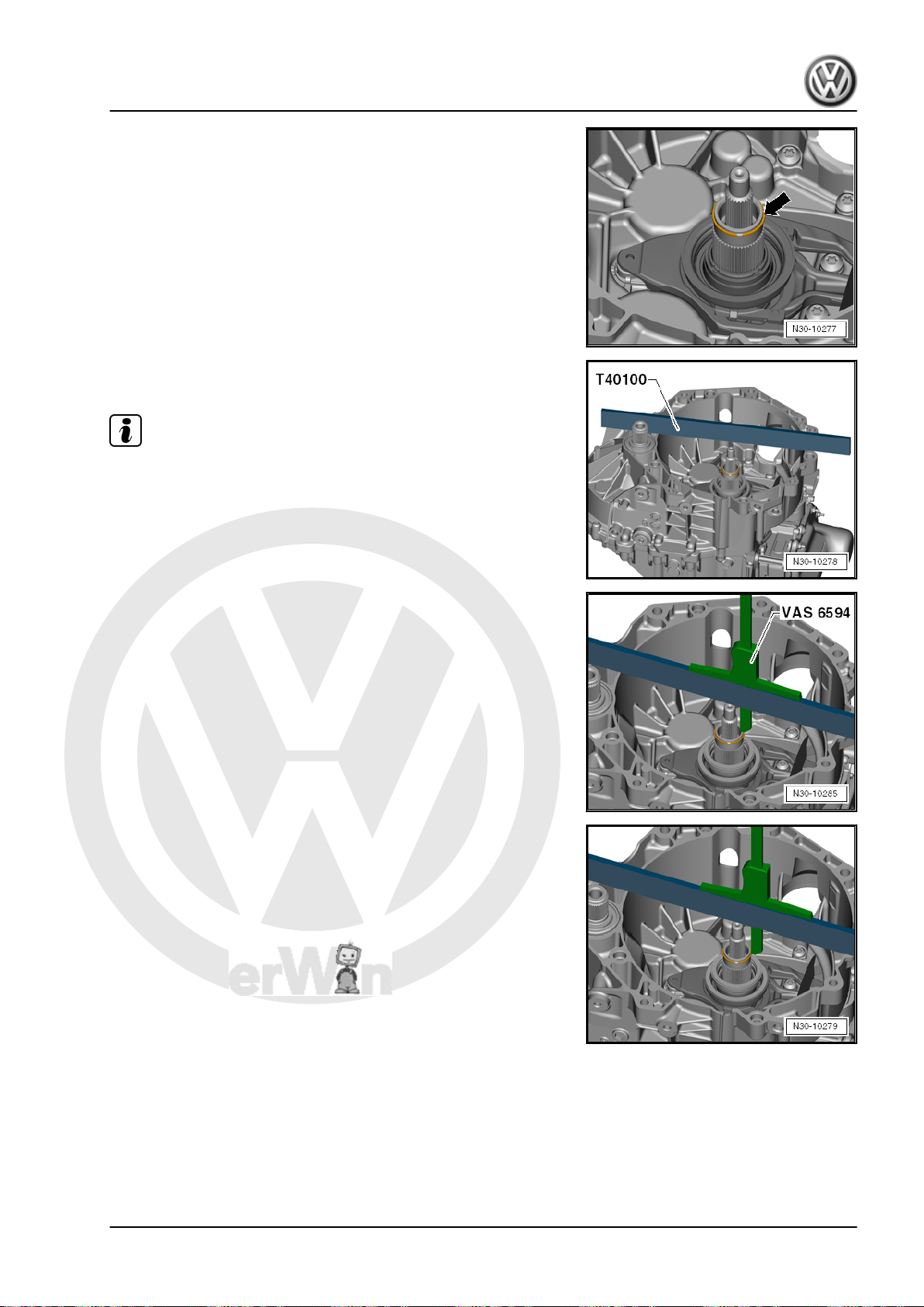
– Install retaining ring of outer input shaft -arrow-.
– Place a ruler -T40100- on its side on flange of clutch housing.
It should lie sideways on shaft end.
Note
Ruler -T40100- should remain in this position during subsequent
measurements. Do not turn over, do not remove.
– Place digital depth gauge onto outer input shaft.
– “Zero” depth gauge.
– Measure distance from retaining ring.
– Note down result and call it “B”.
Example: “B” = 2.91 millimetres
1. Removing and installing the dual clutch 15
Page 20
P
r
o
t
e
c
t
e
d
b
y
c
o
p
y
r
i
g
h
t
.
C
o
p
y
i
n
g
f
o
r
p
r
i
v
a
t
e
o
r
c
o
m
m
e
r
c
i
a
l
p
u
r
p
o
s
e
s
,
i
n
p
a
r
t
o
r
i
n
w
h
o
l
e
,
i
s
n
o
t
p
e
r
m
i
t
t
e
d
u
n
l
e
s
s
a
u
t
h
o
r
i
s
e
d
b
y
V
o
l
k
s
w
a
g
e
n
A
G
.
V
o
l
k
s
w
a
g
e
n
A
G
d
o
e
s
n
o
t
g
u
a
r
a
n
t
e
e
o
r
a
c
c
e
p
t
a
n
y
l
i
a
b
i
l
i
t
y
w
i
t
h
r
e
s
p
e
c
t
t
o
t
h
e
c
o
r
r
e
c
t
n
e
s
s
o
f
i
n
f
o
r
m
a
t
i
o
n
i
n
t
h
i
s
d
o
c
u
m
e
n
t
.
C
o
p
y
r
i
g
h
t
b
y
V
o
l
k
s
w
a
g
e
n
A
G
.
Golf Variant 2007 ➤ , Golf Variant 2010 ➤ , Jetta 2005 ➤ , Jetta 2011 ➤
7-speed dual clutch gearbox 0AM - Edition 07.2010
– Measure dimension “B” again on opposite side.
Note
Do not measure on ring joint. This could force ring away at that
point and falsify measuring result.
– Remove retaining ring again.
This ring is not allowed to be installed again!
– Calculate average of both measuring results.
Example:
Dimension “B” = B1+B22 = 2,91+3,02 = 2.96
This dimension “B” is needed in the following calculations.
In the following sample calculations, “B” should be 2.96 mm. The
dimension given for “B” is and example. The value for “B” may be
different in another gearbox.
There are 2 clutches, therefore there are 2 setting procedures to
follow.
Each measurement requires different preparatory measures, as
well as a few calculations. Please comply with the following work‐
ing procedures.
Start by calculating shim for clutch “K 1”.
Do not insert any shim!
– Place gauge block -T10374- on “large” engagement bearing.
– Press once onto gauge block -T10374- whilst turning.
In this way, it is possible to observe how the engagement bearing
turns. This means gauge block -T10374- also “sits” correctly on
bearing.
– Place digital depth gauge “at top” onto outer input shaft.
Ruler -T40100- is already “on its side” on gearbox flange
⇒ page 15 .
16 Rep. Gr.30 - Clutch
Page 21
P
r
o
t
e
c
t
e
d
b
y
c
o
p
y
r
i
g
h
t
.
C
o
p
y
i
n
g
f
o
r
p
r
i
v
a
t
e
o
r
c
o
m
m
e
r
c
i
a
l
p
u
r
p
o
s
e
s
,
i
n
p
a
r
t
o
r
i
n
w
h
o
l
e
,
i
s
n
o
t
p
e
r
m
i
t
t
e
d
u
n
l
e
s
s
a
u
t
h
o
r
i
s
e
d
b
y
V
o
l
k
s
w
a
g
e
n
A
G
.
V
o
l
k
s
w
a
g
e
n
A
G
d
o
e
s
n
o
t
g
u
a
r
a
n
t
e
e
o
r
a
c
c
e
p
t
a
n
y
l
i
a
b
i
l
i
t
y
w
i
t
h
r
e
s
p
e
c
t
t
o
t
h
e
c
o
r
r
e
c
t
n
e
s
s
o
f
i
n
f
o
r
m
a
t
i
o
n
i
n
t
h
i
s
d
o
c
u
m
e
n
t
.
C
o
p
y
r
i
g
h
t
b
y
V
o
l
k
s
w
a
g
e
n
A
G
.
Golf Variant 2007 ➤ , Golf Variant 2010 ➤ , Jetta 2005 ➤ , Jetta 2011 ➤
7-speed dual clutch gearbox 0AM - Edition 07.2010
– Measure distance from “shaft end” to gauge block -T10374- .
1. Removing and installing the dual clutch 17
Page 22
P
r
o
t
e
c
t
e
d
b
y
c
o
p
y
r
i
g
h
t
.
C
o
p
y
i
n
g
f
o
r
p
r
i
v
a
t
e
o
r
c
o
m
m
e
r
c
i
a
l
p
u
r
p
o
s
e
s
,
i
n
p
a
r
t
o
r
i
n
w
h
o
l
e
,
i
s
n
o
t
p
e
r
m
i
t
t
e
d
u
n
l
e
s
s
a
u
t
h
o
r
i
s
e
d
b
y
V
o
l
k
s
w
a
g
e
n
A
G
.
V
o
l
k
s
w
a
g
e
n
A
G
d
o
e
s
n
o
t
g
u
a
r
a
n
t
e
e
o
r
a
c
c
e
p
t
a
n
y
l
i
a
b
i
l
i
t
y
w
i
t
h
r
e
s
p
e
c
t
t
o
t
h
e
c
o
r
r
e
c
t
n
e
s
s
o
f
i
n
f
o
r
m
a
t
i
o
n
i
n
t
h
i
s
d
o
c
u
m
e
n
t
.
C
o
p
y
r
i
g
h
t
b
y
V
o
l
k
s
w
a
g
e
n
A
G
.
Golf Variant 2007 ➤ , Golf Variant 2010 ➤ , Jetta 2005 ➤ , Jetta 2011 ➤
7-speed dual clutch gearbox 0AM - Edition 07.2010
– To make sure this measurement is as accurate as possible,
position digital depth gauge twice at opposite sides.
This allows the value to be found even more accurately, because
the inaccuracy caused by “tilting” on the engagement bearing is
minimised.
– Calculate average of both measurements onto gauge block -
T10374- .
– Note down this value and call it “A1”.
Example:
Dimension “A1” = 2,61+2,812 = 2.71
Example: “A1” = 2.71 millimetres
Next calculation:
“A1” minus “B” plus height of gauge block -T10374- = Depth of
engagement bearing of clutch 1.
Height of gauge block -T10374- is always the same. It is: 51.81
mm.
Sample calculation:
2.71 mm minus 2.96 mm plus 51.81 mm = 51.56 mm.
You have now calculated value for how deep engagement bear‐
ing is actually seated inside gearbox.
Depth of bearing in each gearbox should be 50.08 millimetres.
Subtract nominal dimension “50.08 millimetres” from this actual
value. This gives result for actual gap of clutch 1.
– Continue the calculation:
Calculated value (in example: 51.56 mm) minus nominal dimen‐
sion = gap of clutch.
Sample calculation:
51.56 mm minus “50.08 millimetres” = gap of clutch 1 = 1.48 mm.
Now tolerances in dual clutch must be introduced into this calcu‐
lation. Procedure for this is very simple:
– Please read off value of clutch tolerance of “new” clutch.
A value between minus 0.40 and plus 0.40 millimetres is provided
with a new clutch.
– Make a note of this value.
Example 1: “- 0.40” is indicated on your clutch.
The previous calculation for “K 1”: “your calculated” gap minus
value of clutch 1 =
1.48 mm minus 0.40 = 1.08 mm.
Example 2: “+ 0.20” is indicated on your clutch.
Then, the last calculation of “K 1” is as follows: 1.48 mm plus 0.20
= 1.68 mm.
– Refer to table to find correct shim and install.
18 Rep. Gr.30 - Clutch
Page 23
P
r
o
t
e
c
t
e
d
b
y
c
o
p
y
r
i
g
h
t
.
C
o
p
y
i
n
g
f
o
r
p
r
i
v
a
t
e
o
r
c
o
m
m
e
r
c
i
a
l
p
u
r
p
o
s
e
s
,
i
n
p
a
r
t
o
r
i
n
w
h
o
l
e
,
i
s
n
o
t
p
e
r
m
i
t
t
e
d
u
n
l
e
s
s
a
u
t
h
o
r
i
s
e
d
b
y
V
o
l
k
s
w
a
g
e
n
A
G
.
V
o
l
k
s
w
a
g
e
n
A
G
d
o
e
s
n
o
t
g
u
a
r
a
n
t
e
e
o
r
a
c
c
e
p
t
a
n
y
l
i
a
b
i
l
i
t
y
w
i
t
h
r
e
s
p
e
c
t
t
o
t
h
e
c
o
r
r
e
c
t
n
e
s
s
o
f
i
n
f
o
r
m
a
t
i
o
n
i
n
t
h
i
s
d
o
c
u
m
e
n
t
.
C
o
p
y
r
i
g
h
t
b
y
V
o
l
k
s
w
a
g
e
n
A
G
.
Golf Variant 2007 ➤ , Golf Variant 2010 ➤ , Jetta 2005 ➤ , Jetta 2011 ➤
7-speed dual clutch gearbox 0AM - Edition 07.2010
Calculated shim thickness Shim to be installed (in milli‐
metres)
from to
0.31 0.90 0.8
0.91 1.10 1.0
1.11 1.30 1.2
1.31 1.50 1.4
1.51 1.70 1.6
1.71 1.90 1.8
1.91 2.10 2.0
2.11 2.30 2.2
2.31 2.50 2.4
2.51 2.70 2.6
2.71 3.30 2.8
– From the supplied shims, select the one that is required.
Later on, only insert this 1 shim. Not 2 shims.
With this, you have found “correct” shim for “K 1”. Please install
this shim during subsequent clutch installation.
– Continue setting for clutch “K 2”.
Calculate shim for clutch “K 2”.
– Only insert small bearing.
WARNING
Do not insert any shim!
Small engagement bearing only fits in one position due to 4
grooves.
1. Removing and installing the dual clutch 19
Page 24
P
r
o
t
e
c
t
e
d
b
y
c
o
p
y
r
i
g
h
t
.
C
o
p
y
i
n
g
f
o
r
p
r
i
v
a
t
e
o
r
c
o
m
m
e
r
c
i
a
l
p
u
r
p
o
s
e
s
,
i
n
p
a
r
t
o
r
i
n
w
h
o
l
e
,
i
s
n
o
t
p
e
r
m
i
t
t
e
d
u
n
l
e
s
s
a
u
t
h
o
r
i
s
e
d
b
y
V
o
l
k
s
w
a
g
e
n
A
G
.
V
o
l
k
s
w
a
g
e
n
A
G
d
o
e
s
n
o
t
g
u
a
r
a
n
t
e
e
o
r
a
c
c
e
p
t
a
n
y
l
i
a
b
i
l
i
t
y
w
i
t
h
r
e
s
p
e
c
t
t
o
t
h
e
c
o
r
r
e
c
t
n
e
s
s
o
f
i
n
f
o
r
m
a
t
i
o
n
i
n
t
h
i
s
d
o
c
u
m
e
n
t
.
C
o
p
y
r
i
g
h
t
b
y
V
o
l
k
s
w
a
g
e
n
A
G
.
Golf Variant 2007 ➤ , Golf Variant 2010 ➤ , Jetta 2005 ➤ , Jetta 2011 ➤
7-speed dual clutch gearbox 0AM - Edition 07.2010
– By “turning”, check whether small engagement bearing is in‐
stalled correctly and that grooves are seated correctly.
– Place gauge block -T10374- on small bearing “with large
opening upwards”.
– Place digital depth gauge “at top” onto outer input shaft.
– “Zero” depth gauge.
– Measure distance from “shaft end” into gauge block -T10374- .
20 Rep. Gr.30 - Clutch
Page 25
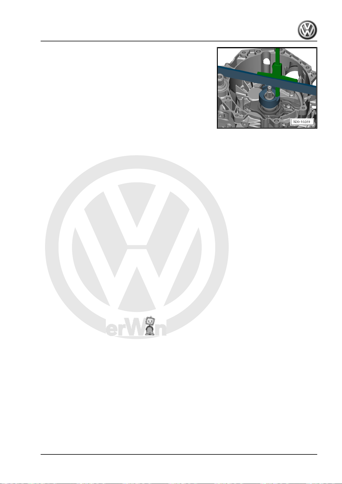
P
r
o
t
e
c
t
e
d
b
y
c
o
p
y
r
i
g
h
t
.
C
o
p
y
i
n
g
f
o
r
p
r
i
v
a
t
e
o
r
c
o
m
m
e
r
c
i
a
l
p
u
r
p
o
s
e
s
,
i
n
p
a
r
t
o
r
i
n
w
h
o
l
e
,
i
s
n
o
t
p
e
r
m
i
t
t
e
d
u
n
l
e
s
s
a
u
t
h
o
r
i
s
e
d
b
y
V
o
l
k
s
w
a
g
e
n
A
G
.
V
o
l
k
s
w
a
g
e
n
A
G
d
o
e
s
n
o
t
g
u
a
r
a
n
t
e
e
o
r
a
c
c
e
p
t
a
n
y
l
i
a
b
i
l
i
t
y
w
i
t
h
r
e
s
p
e
c
t
t
o
t
h
e
c
o
r
r
e
c
t
n
e
s
s
o
f
i
n
f
o
r
m
a
t
i
o
n
i
n
t
h
i
s
d
o
c
u
m
e
n
t
.
C
o
p
y
r
i
g
h
t
b
y
V
o
l
k
s
w
a
g
e
n
A
G
.
Golf Variant 2007 ➤ , Golf Variant 2010 ➤ , Jetta 2005 ➤ , Jetta 2011 ➤
7-speed dual clutch gearbox 0AM - Edition 07.2010
– To make sure this measurement is as accurate as possible,
position digital depth gauge twice at opposite sides.
This allows the value to be found even more accurately, because
the inaccuracy caused by “tilting” on the engagement bearing is
minimised.
– Calculate average of both measurements onto gauge block -
T10374- .
– Note down this value and call it “A2”.
Example:
Dimension “A2” = 2,50+2,542 = 2.52
Example: “A2” = 2.52 millimetres
Next calculation:
“A2” minus “B” plus height of gauge block -T10374- = Depth of
engagement bearing of clutch 2.
Height of gauge block -T10374- is always the same. On inside, it
is: 36.20 mm.
Sample calculation:
2.52 mm minus 2.96 mm plus 36.20 mm = 35.76 mm.
You have now calculated value for how deep engagement bear‐
ing is actually seated inside gearbox.
Depth of bearing in each gearbox should be 34.35 millimetres.
Subtract nominal dimension “34.35 millimetres” from this actual
value. This gives result for actual gap of clutch 2.
– Continue the calculation:
Calculated value (in example: 35.76 mm) minus nominal dimen‐
sion = gap of clutch.
Sample calculation:
35.76 mm minus “34.35 millimetres” = gap of clutch 2 = 1.41mm.
Now tolerances in dual clutch must be introduced into this calcu‐
lation. Procedure for this is very simple:
– Please read off value of clutch tolerance of “new” clutch.
A value between minus 0.40 and plus 0.40 millimetres is provided
with a new clutch.
– Make a note of this value.
Example 1: “- 0.40” is indicated on your clutch.
The previous calculation for “K 2”: “your calculated” gap minus
value of clutch 2 =
1.41 mm minus 0.40 = 1.01 mm.
Example 2: “+ 0.20” is indicated on your clutch.
Then, the last calculation of “K 2” is as follows: 1.41 mm plus 0.20
= 1.61 mm.
– Refer to table to find correct shim.
1. Removing and installing the dual clutch 21
Page 26
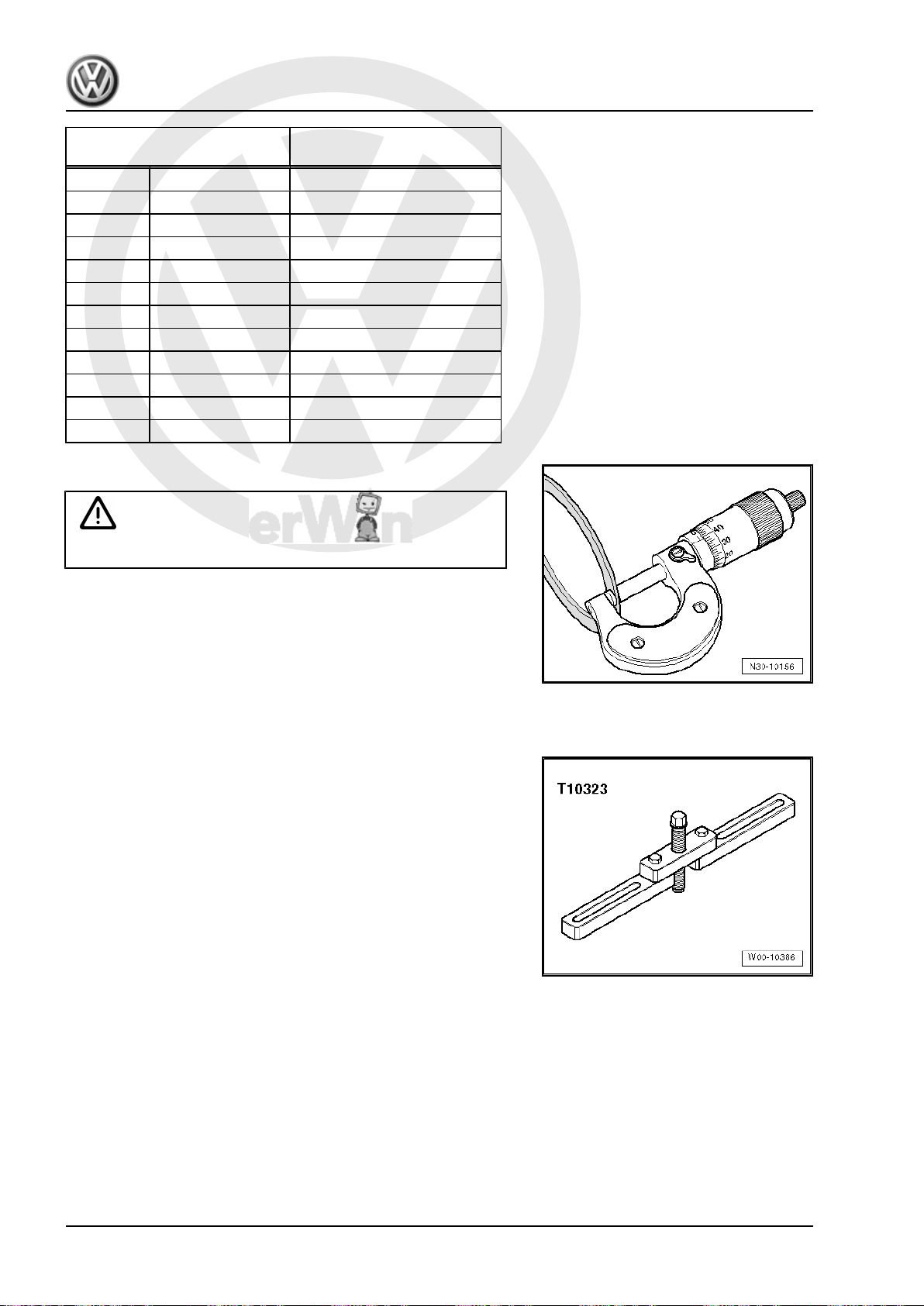
P
r
o
t
e
c
t
e
d
b
y
c
o
p
y
r
i
g
h
t
.
C
o
p
y
i
n
g
f
o
r
p
r
i
v
a
t
e
o
r
c
o
m
m
e
r
c
i
a
l
p
u
r
p
o
s
e
s
,
i
n
p
a
r
t
o
r
i
n
w
h
o
l
e
,
i
s
n
o
t
p
e
r
m
i
t
t
e
d
u
n
l
e
s
s
a
u
t
h
o
r
i
s
e
d
b
y
V
o
l
k
s
w
a
g
e
n
A
G
.
V
o
l
k
s
w
a
g
e
n
A
G
d
o
e
s
n
o
t
g
u
a
r
a
n
t
e
e
o
r
a
c
c
e
p
t
a
n
y
l
i
a
b
i
l
i
t
y
w
i
t
h
r
e
s
p
e
c
t
t
o
t
h
e
c
o
r
r
e
c
t
n
e
s
s
o
f
i
n
f
o
r
m
a
t
i
o
n
i
n
t
h
i
s
d
o
c
u
m
e
n
t
.
C
o
p
y
r
i
g
h
t
b
y
V
o
l
k
s
w
a
g
e
n
A
G
.
Golf Variant 2007 ➤ , Golf Variant 2010 ➤ , Jetta 2005 ➤ , Jetta 2011 ➤
7-speed dual clutch gearbox 0AM - Edition 07.2010
Calculated shim thickness Shim to be installed (in milli‐
from to
0.31 0.90 0.8
0.91 1.10 1.0
1.11 1.30 1.2
1.31 1.50 1.4
1.51 1.70 1.6
1.71 1.90 1.8
1.91 2.10 2.0
2.11 2.30 2.2
2.31 2.50 2.4
2.51 2.70 2.6
2.71 3.30 2.8
– From the supplied shims, select the one that is required.
WARNING
Later on, only insert this 1 shim. Not 2 shims.
With this, you also have found “correct” shim for “K 2”. Please
metres)
install this shim during subsequent clutch installation. This shim
should be under small engagement bearing.
1.3 Installing dual clutch
Special tools and workshop equipment required
♦ Support device -T10323-
22 Rep. Gr.30 - Clutch
Page 27
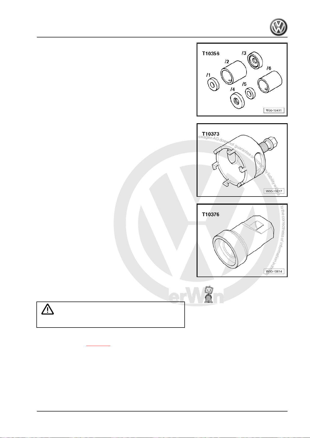
P
r
o
t
e
c
t
e
d
b
y
c
o
p
y
r
i
g
h
t
.
C
o
p
y
i
n
g
f
o
r
p
r
i
v
a
t
e
o
r
c
o
m
m
e
r
c
i
a
l
p
u
r
p
o
s
e
s
,
i
n
p
a
r
t
o
r
i
n
w
h
o
l
e
,
i
s
n
o
t
p
e
r
m
i
t
t
e
d
u
n
l
e
s
s
a
u
t
h
o
r
i
s
e
d
b
y
V
o
l
k
s
w
a
g
e
n
A
G
.
V
o
l
k
s
w
a
g
e
n
A
G
d
o
e
s
n
o
t
g
u
a
r
a
n
t
e
e
o
r
a
c
c
e
p
t
a
n
y
l
i
a
b
i
l
i
t
y
w
i
t
h
r
e
s
p
e
c
t
t
o
t
h
e
c
o
r
r
e
c
t
n
e
s
s
o
f
i
n
f
o
r
m
a
t
i
o
n
i
n
t
h
i
s
d
o
c
u
m
e
n
t
.
C
o
p
y
r
i
g
h
t
b
y
V
o
l
k
s
w
a
g
e
n
A
G
.
Golf Variant 2007 ➤ , Golf Variant 2010 ➤ , Jetta 2005 ➤ , Jetta 2011 ➤
♦ Assembly tool -T10356-
♦ Puller -T10373-
♦ Thrust piece -T10376-
♦ Adhesive -AMV 195 KD1 01-
Perform the following steps:
Caution
7-speed dual clutch gearbox 0AM - Edition 07.2010
Do not oil or grease anything!
Before clutch is installed, position of engagement bearings “K 1
and K 2” must be set ⇒ page 12 .
1. Removing and installing the dual clutch 23
Page 28
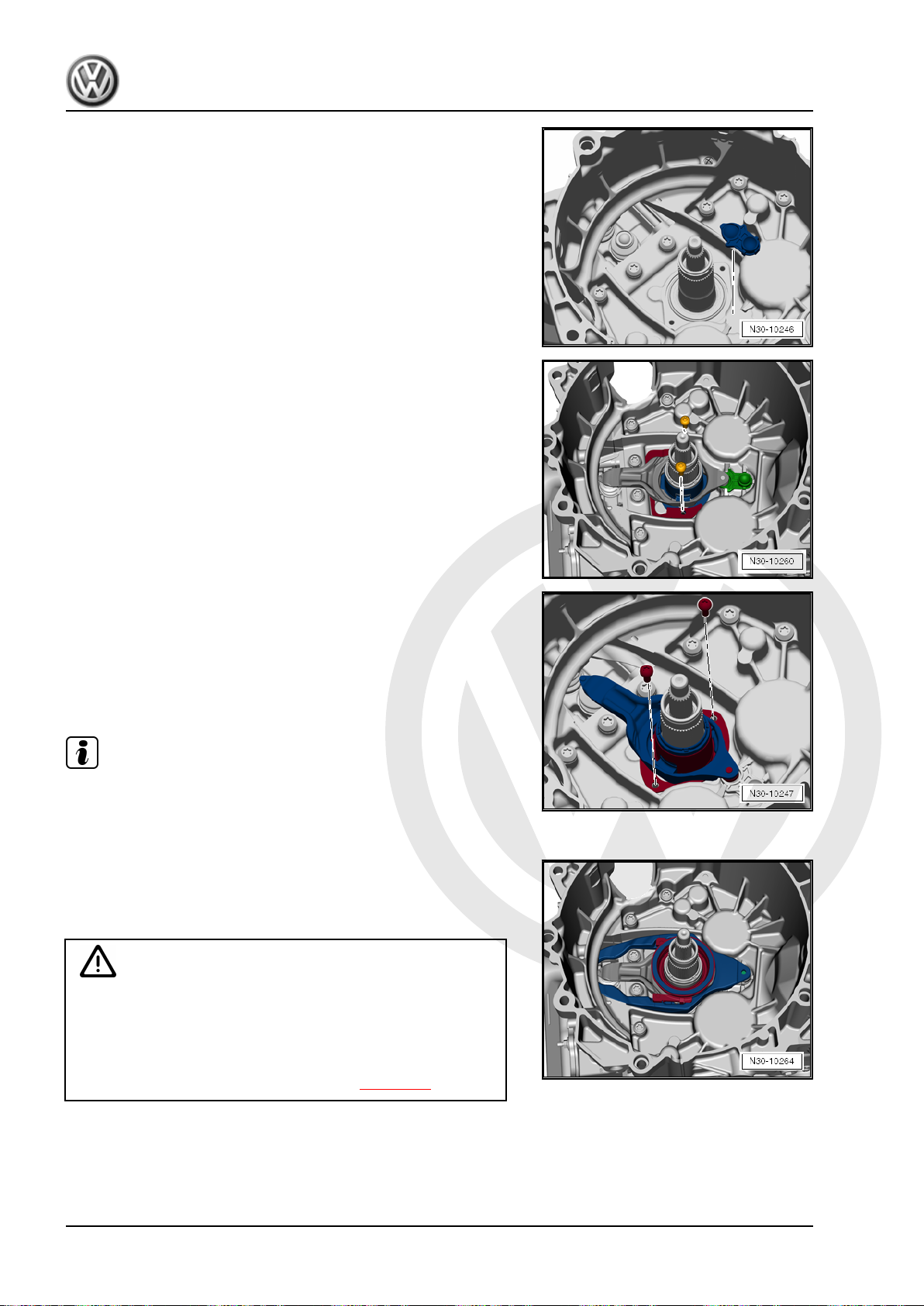
P
r
o
t
e
c
t
e
d
b
y
c
o
p
y
r
i
g
h
t
.
C
o
p
y
i
n
g
f
o
r
p
r
i
v
a
t
e
o
r
c
o
m
m
e
r
c
i
a
l
p
u
r
p
o
s
e
s
,
i
n
p
a
r
t
o
r
i
n
w
h
o
l
e
,
i
s
n
o
t
p
e
r
m
i
t
t
e
d
u
n
l
e
s
s
a
u
t
h
o
r
i
s
e
d
b
y
V
o
l
k
s
w
a
g
e
n
A
G
.
V
o
l
k
s
w
a
g
e
n
A
G
d
o
e
s
n
o
t
g
u
a
r
a
n
t
e
e
o
r
a
c
c
e
p
t
a
n
y
l
i
a
b
i
l
i
t
y
w
i
t
h
r
e
s
p
e
c
t
t
o
t
h
e
c
o
r
r
e
c
t
n
e
s
s
o
f
i
n
f
o
r
m
a
t
i
o
n
i
n
t
h
i
s
d
o
c
u
m
e
n
t
.
C
o
p
y
r
i
g
h
t
b
y
V
o
l
k
s
w
a
g
e
n
A
G
.
Golf Variant 2007 ➤ , Golf Variant 2010 ➤ , Jetta 2005 ➤ , Jetta 2011 ➤
7-speed dual clutch gearbox 0AM - Edition 07.2010
– Insert plastic retainer of engaging lever and check for correct
seating.
– Install small engaging lever with clip.
Sleeve with its retaining plate fits only in one position.
Only a few, “older gearboxes” do not have a clip.
“New” clutches always have one clip.
– Check engaging lever is properly seated.
– Screw on engaging lever with 2 new bolts.
Torque setting: 8 Nm + 90°
Note
Mounting for engaging lever and entire mechanism of engage‐
ment bearing must be dry and free from oil or grease. If neces‐
sary, clean these components with a cloth.
– Insert 2nd, “larger” engaging lever.
This “larger” lever is for clutch “K 1”.
– Check both engaging levers are seated correctly.
Caution
Before continuing with assembly, check whether clutch needs
to be adjusted.
Do not continue with the assembly before the clutch has been
adjusted!
Adjust positions of engagement bearings ⇒ page 12 .
24 Rep. Gr.30 - Clutch
Page 29
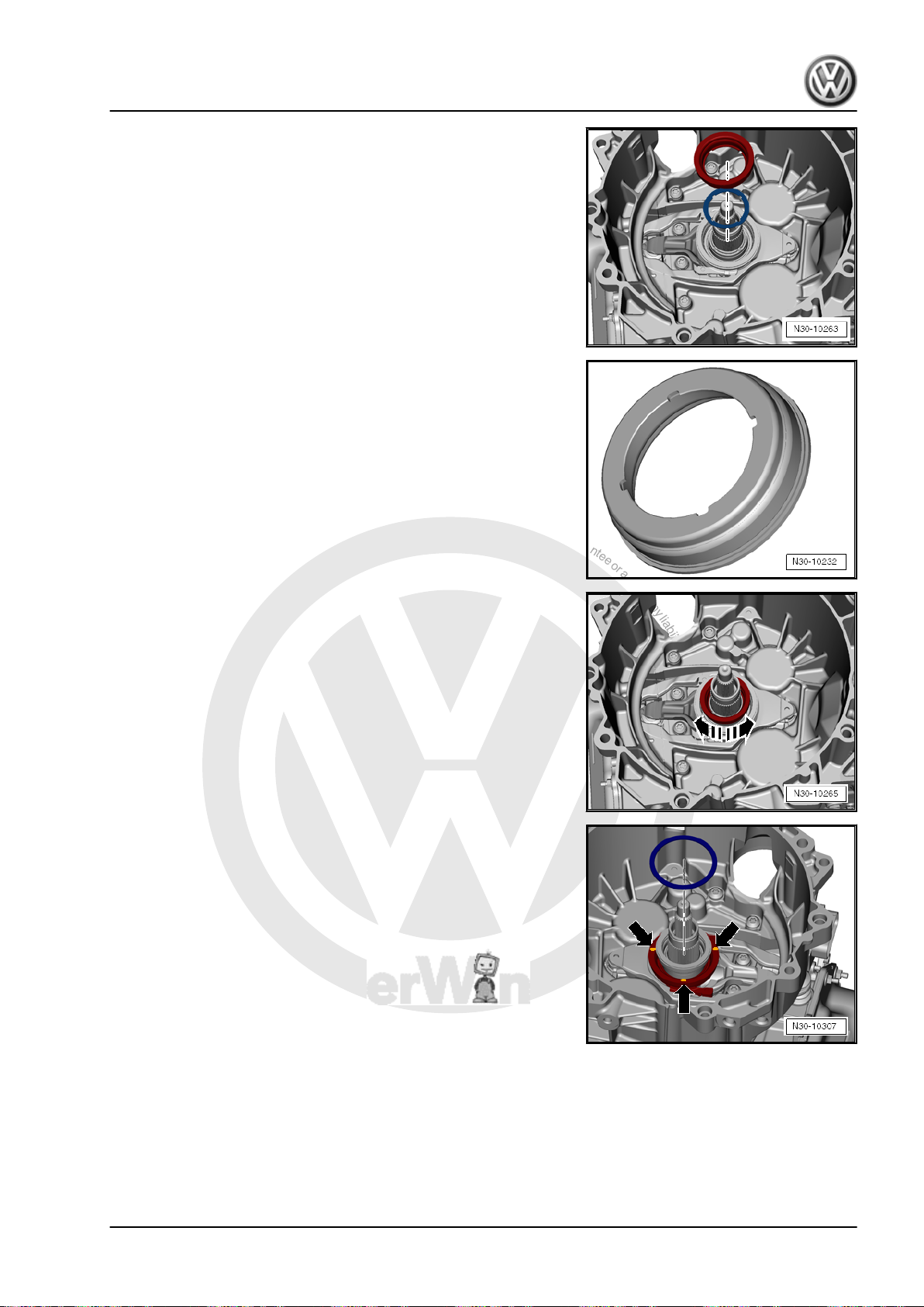
P
r
o
t
e
c
t
e
d
b
y
c
o
p
y
r
i
g
h
t
.
C
o
p
y
i
n
g
f
o
r
p
r
i
v
a
t
e
o
r
c
o
m
m
e
r
c
i
a
l
p
u
r
p
o
s
e
s
,
i
n
p
a
r
t
o
r
i
n
w
h
o
l
e
,
i
s
n
o
t
p
e
r
m
i
t
t
e
d
u
n
l
e
s
s
a
u
t
h
o
r
i
s
e
d
b
y
V
o
l
k
s
w
a
g
e
n
A
G
.
V
o
l
k
s
w
a
g
e
n
A
G
d
o
e
s
n
o
t
g
u
a
r
a
n
t
e
e
o
r
a
c
c
e
p
t
a
n
y
l
i
a
b
i
l
i
t
y
w
i
t
h
r
e
s
p
e
c
t
t
o
t
h
e
c
o
r
r
e
c
t
n
e
s
s
o
f
i
n
f
o
r
m
a
t
i
o
n
i
n
t
h
i
s
d
o
c
u
m
e
n
t
.
C
o
p
y
r
i
g
h
t
b
y
V
o
l
k
s
w
a
g
e
n
A
G
.
Golf Variant 2007 ➤ , Golf Variant 2010 ➤ , Jetta 2005 ➤ , Jetta 2011 ➤
7-speed dual clutch gearbox 0AM - Edition 07.2010
– Insert small engagement bearing with measured shim.
Shim should be under small engagement bearing. Therefore, in‐
sert shim first.
Small engagement bearing only fits in one position due to 4
grooves.
If clutch has been replaced, shim should also be under bearing.
– By “turning” bearing, check whether it is installed correctly and
that grooves are seated correctly.
– Secure shim using 3 drops of glue -AMV 195 KD1 01- .
This prevents shim from slipping out of its seat when clutch is
inserted.
Large shim is for clutch “K 1”, small one for clutch “K 2”.
– Turn back spindle of puller -T10373- .
1. Removing and installing the dual clutch 25
Page 30
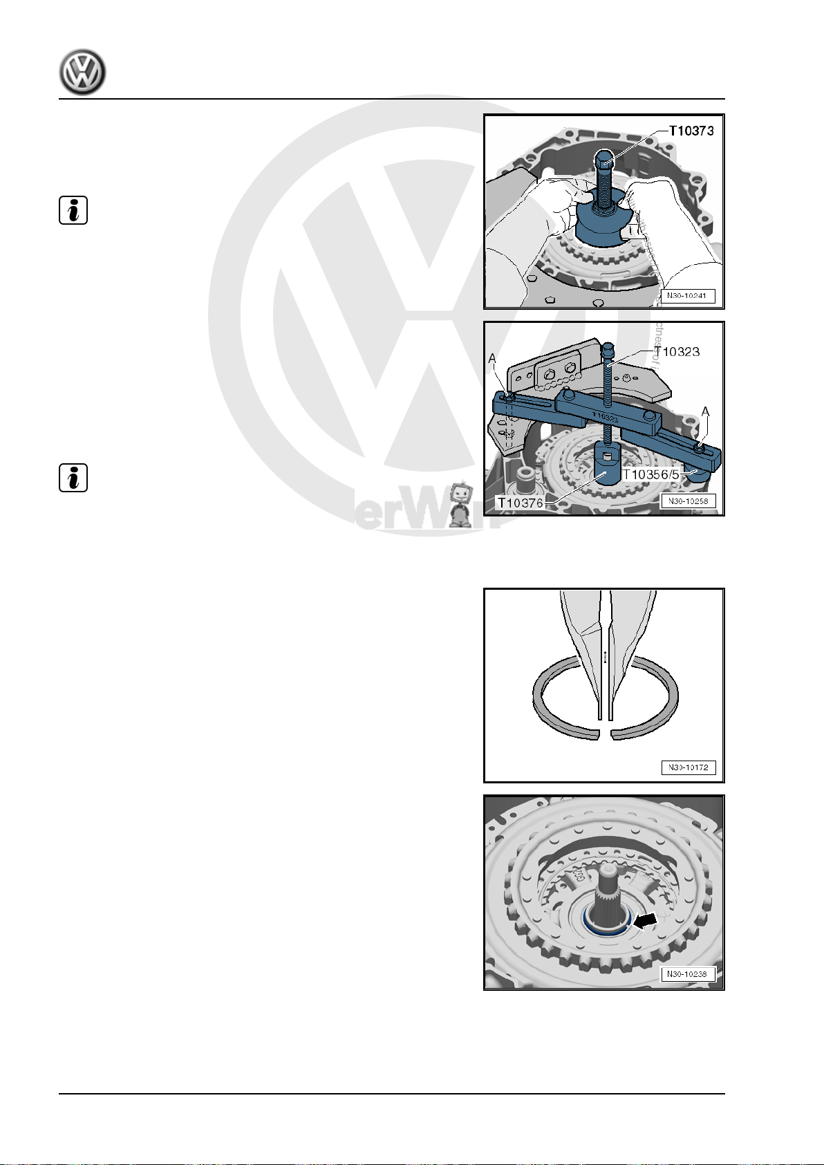
P
r
o
t
e
c
t
e
d
b
y
c
o
p
y
r
i
g
h
t
.
C
o
p
y
i
n
g
f
o
r
p
r
i
v
a
t
e
o
r
c
o
m
m
e
r
c
i
a
l
p
u
r
p
o
s
e
s
,
i
n
p
a
r
t
o
r
i
n
w
h
o
l
e
,
i
s
n
o
t
p
e
r
m
i
t
t
e
d
u
n
l
e
s
s
a
u
t
h
o
r
i
s
e
d
b
y
V
o
l
k
s
w
a
g
e
n
A
G
.
V
o
l
k
s
w
a
g
e
n
A
G
d
o
e
s
n
o
t
g
u
a
r
a
n
t
e
e
o
r
a
c
c
e
p
t
a
n
y
l
i
a
b
i
l
i
t
y
w
i
t
h
r
e
s
p
e
c
t
t
o
t
h
e
c
o
r
r
e
c
t
n
e
s
s
o
f
i
n
f
o
r
m
a
t
i
o
n
i
n
t
h
i
s
d
o
c
u
m
e
n
t
.
C
o
p
y
r
i
g
h
t
b
y
V
o
l
k
s
w
a
g
e
n
A
G
.
Golf Variant 2007 ➤ , Golf Variant 2010 ➤ , Jetta 2005 ➤ , Jetta 2011 ➤
7-speed dual clutch gearbox 0AM - Edition 07.2010
– Insert clutch.
– Use puller -T10373- to insert clutch into gearbox.
– Turn spindle “back” first.
Note
The clutch is self-adjusting. Shocks can have an effect on this
adjusting device. Therefore, please do not drop the clutch. Do not
left the clutch drop into the gearbox either when installing the
clutch.
– Press clutch on onto stop.
Support bracket -T10323- fits on all 0AM gearboxes.
– Make sure that you place support bracket -T10323- in parallel
to the gearbox flange.
Secure engine support with bolts -A-, as required with nuts.
– Push clutch down via spindle.
Note
Place a hand on clutch whilst pressing on. You will be able to feel
a slight rattling. Rattling means the clutch is being pressed onto
its press seat. In the same way, you can also “feel” the stop when
the clutch has reached its seat.
Installation position of retaining ring: Joint of retaining ring is “nar‐
rower at top”.
If you can insert retaining ring -arrow-, clutch is correctly pressed
on to stop.
– Insert new retaining ring -arrow-.
26 Rep. Gr.30 - Clutch
Page 31

P
r
o
t
e
c
t
e
d
b
y
c
o
p
y
r
i
g
h
t
.
C
o
p
y
i
n
g
f
o
r
p
r
i
v
a
t
e
o
r
c
o
m
m
e
r
c
i
a
l
p
u
r
p
o
s
e
s
,
i
n
p
a
r
t
o
r
i
n
w
h
o
l
e
,
i
s
n
o
t
p
e
r
m
i
t
t
e
d
u
n
l
e
s
s
a
u
t
h
o
r
i
s
e
d
b
y
V
o
l
k
s
w
a
g
e
n
A
G
.
V
o
l
k
s
w
a
g
e
n
A
G
d
o
e
s
n
o
t
g
u
a
r
a
n
t
e
e
o
r
a
c
c
e
p
t
a
n
y
l
i
a
b
i
l
i
t
y
w
i
t
h
r
e
s
p
e
c
t
t
o
t
h
e
c
o
r
r
e
c
t
n
e
s
s
o
f
i
n
f
o
r
m
a
t
i
o
n
i
n
t
h
i
s
d
o
c
u
m
e
n
t
.
C
o
p
y
r
i
g
h
t
b
y
V
o
l
k
s
w
a
g
e
n
A
G
.
Golf Variant 2007 ➤ , Golf Variant 2010 ➤ , Jetta 2005 ➤ , Jetta 2011 ➤
7-speed dual clutch gearbox 0AM - Edition 07.2010
– To enable clutch to find its installation position already, turn
clutch against puller -T10373- by hand.
• Now turn clutch by hand, without using a tool.
In this way, clutch slides against retaining ring. Do not use any
other tool.
Pressing on causes “clutch to locate at bottom” on input shaft.
Clutch should only be pulled up far enough for it to contact re‐
taining ring.
Then insert hub.
Hub has a “large” tooth and therefore only fits in one position.
“Large” tooth has a mark on -engine end- -arrow-.
1. Removing and installing the dual clutch 27
Page 32

P
r
o
t
e
c
t
e
d
b
y
c
o
p
y
r
i
g
h
t
.
C
o
p
y
i
n
g
f
o
r
p
r
i
v
a
t
e
o
r
c
o
m
m
e
r
c
i
a
l
p
u
r
p
o
s
e
s
,
i
n
p
a
r
t
o
r
i
n
w
h
o
l
e
,
i
s
n
o
t
p
e
r
m
i
t
t
e
d
u
n
l
e
s
s
a
u
t
h
o
r
i
s
e
d
b
y
V
o
l
k
s
w
a
g
e
n
A
G
.
V
o
l
k
s
w
a
g
e
n
A
G
d
o
e
s
n
o
t
g
u
a
r
a
n
t
e
e
o
r
a
c
c
e
p
t
a
n
y
l
i
a
b
i
l
i
t
y
w
i
t
h
r
e
s
p
e
c
t
t
o
t
h
e
c
o
r
r
e
c
t
n
e
s
s
o
f
i
n
f
o
r
m
a
t
i
o
n
i
n
t
h
i
s
d
o
c
u
m
e
n
t
.
C
o
p
y
r
i
g
h
t
b
y
V
o
l
k
s
w
a
g
e
n
A
G
.
Golf Variant 2007 ➤ , Golf Variant 2010 ➤ , Jetta 2005 ➤ , Jetta 2011 ➤
7-speed dual clutch gearbox 0AM - Edition 07.2010
– Insert retaining ring for hub -arrow-.
Installation position: Joint of ring must point towards “hub” on
clutch.
– Turn clutch by hand and observe “small” engaging lever whilst
turning.
Engaging levers must remain “still” in their position whilst this is
being done. They are not allowed to move up and down.
If an engaging lever moves up and down, then shim is not properly
seated.
28 Rep. Gr.30 - Clutch
Page 33

P
r
o
t
e
c
t
e
d
b
y
c
o
p
y
r
i
g
h
t
.
C
o
p
y
i
n
g
f
o
r
p
r
i
v
a
t
e
o
r
c
o
m
m
e
r
c
i
a
l
p
u
r
p
o
s
e
s
,
i
n
p
a
r
t
o
r
i
n
w
h
o
l
e
,
i
s
n
o
t
p
e
r
m
i
t
t
e
d
u
n
l
e
s
s
a
u
t
h
o
r
i
s
e
d
b
y
V
o
l
k
s
w
a
g
e
n
A
G
.
V
o
l
k
s
w
a
g
e
n
A
G
d
o
e
s
n
o
t
g
u
a
r
a
n
t
e
e
o
r
a
c
c
e
p
t
a
n
y
l
i
a
b
i
l
i
t
y
w
i
t
h
r
e
s
p
e
c
t
t
o
t
h
e
c
o
r
r
e
c
t
n
e
s
s
o
f
i
n
f
o
r
m
a
t
i
o
n
i
n
t
h
i
s
d
o
c
u
m
e
n
t
.
C
o
p
y
r
i
g
h
t
b
y
V
o
l
k
s
w
a
g
e
n
A
G
.
Golf Variant 2007 ➤ , Golf Variant 2010 ➤ , Jetta 2005 ➤ , Jetta 2011 ➤
7-speed dual clutch gearbox 0AM - Edition 07.2010
– Remove clutch again in this case ⇒ page 8 .
– Look at shims -arrows- precisely.
• Shims must be correctly seated. They must not be damaged.
– Remove plugs and put both breather caps -arrows- back on.
After the gearbox has been installed, you must initiate a basic
adjustment using the ⇒ Vehicle diagnosis, testing and information
system VAS 5051 ⇒ page 7 .
1. Removing and installing the dual clutch 29
Page 34

P
r
o
t
e
c
t
e
d
b
y
c
o
p
y
r
i
g
h
t
.
C
o
p
y
i
n
g
f
o
r
p
r
i
v
a
t
e
o
r
c
o
m
m
e
r
c
i
a
l
p
u
r
p
o
s
e
s
,
i
n
p
a
r
t
o
r
i
n
w
h
o
l
e
,
i
s
n
o
t
p
e
r
m
i
t
t
e
d
u
n
l
e
s
s
a
u
t
h
o
r
i
s
e
d
b
y
V
o
l
k
s
w
a
g
e
n
A
G
.
V
o
l
k
s
w
a
g
e
n
A
G
d
o
e
s
n
o
t
g
u
a
r
a
n
t
e
e
o
r
a
c
c
e
p
t
a
n
y
l
i
a
b
i
l
i
t
y
w
i
t
h
r
e
s
p
e
c
t
t
o
t
h
e
c
o
r
r
e
c
t
n
e
s
s
o
f
i
n
f
o
r
m
a
t
i
o
n
i
n
t
h
i
s
d
o
c
u
m
e
n
t
.
C
o
p
y
r
i
g
h
t
b
y
V
o
l
k
s
w
a
g
e
n
A
G
.
Golf Variant 2007 ➤ , Golf Variant 2010 ➤ , Jetta 2005 ➤ , Jetta 2011 ➤
7-speed dual clutch gearbox 0AM - Edition 07.2010
34 – Controls, housing
1 Renewing gear oil
The gearbox is filled for life. Therefore, there is no need to check
the oil level of this gearbox.
This explains why there is no oil level check.
In case of leaks on gearbox, find out what is the cause and rectify
the faults.
– Raise vehicle.
– Place drip tray under gearbox.
Then drain all gear oil and fill with new oil.
– Then install the drain plug again.
If the gearbox is installed, you must remove the battery and bat‐
tery tray to add oil.
– Remove battery and battery tray -arrows- ⇒ Rep. Gr. 27 ;
Battery; Removing and installing battery .
– Move selector lever to position “P” position.
30 Rep. Gr.34 - Controls, housing
Page 35

P
r
o
t
e
c
t
e
d
b
y
c
o
p
y
r
i
g
h
t
.
C
o
p
y
i
n
g
f
o
r
p
r
i
v
a
t
e
o
r
c
o
m
m
e
r
c
i
a
l
p
u
r
p
o
s
e
s
,
i
n
p
a
r
t
o
r
i
n
w
h
o
l
e
,
i
s
n
o
t
p
e
r
m
i
t
t
e
d
u
n
l
e
s
s
a
u
t
h
o
r
i
s
e
d
b
y
V
o
l
k
s
w
a
g
e
n
A
G
.
V
o
l
k
s
w
a
g
e
n
A
G
d
o
e
s
n
o
t
g
u
a
r
a
n
t
e
e
o
r
a
c
c
e
p
t
a
n
y
l
i
a
b
i
l
i
t
y
w
i
t
h
r
e
s
p
e
c
t
t
o
t
h
e
c
o
r
r
e
c
t
n
e
s
s
o
f
i
n
f
o
r
m
a
t
i
o
n
i
n
t
h
i
s
d
o
c
u
m
e
n
t
.
C
o
p
y
r
i
g
h
t
b
y
V
o
l
k
s
w
a
g
e
n
A
G
.
Golf Variant 2007 ➤ , Golf Variant 2010 ➤ , Jetta 2005 ➤ , Jetta 2011 ➤
7-speed dual clutch gearbox 0AM - Edition 07.2010
– Remove securing clip in -direction of arrow-.
Securing clips for selector lever cable must always be renewed.
– Remove Bowden cable from ball head.
– Use your hand to press lever to stop in direction of cable sup‐
port bracket.
– Note installation position of lever and remove it from selector
shaft.
– If you are unsure, refer to this illustration for guidance.
– Unbolt cover.
Only leaking covers must be renewed. If the cover was not leak‐
ing, it does not need to be renewed.
– Pour 1.7 l of oil in through opening -arrow-.
– Take care not to “spill” any. Gearbox must have precisely 1.7
litres of oil.
Caution
Do not fill any more or any less oil. Malfunctions would result!
– Clean sealing surface on gearbox and on cover.
1. Renewing gear oil 31
Page 36

P
r
o
t
e
c
t
e
d
b
y
c
o
p
y
r
i
g
h
t
.
C
o
p
y
i
n
g
f
o
r
p
r
i
v
a
t
e
o
r
c
o
m
m
e
r
c
i
a
l
p
u
r
p
o
s
e
s
,
i
n
p
a
r
t
o
r
i
n
w
h
o
l
e
,
i
s
n
o
t
p
e
r
m
i
t
t
e
d
u
n
l
e
s
s
a
u
t
h
o
r
i
s
e
d
b
y
V
o
l
k
s
w
a
g
e
n
A
G
.
V
o
l
k
s
w
a
g
e
n
A
G
d
o
e
s
n
o
t
g
u
a
r
a
n
t
e
e
o
r
a
c
c
e
p
t
a
n
y
l
i
a
b
i
l
i
t
y
w
i
t
h
r
e
s
p
e
c
t
t
o
t
h
e
c
o
r
r
e
c
t
n
e
s
s
o
f
i
n
f
o
r
m
a
t
i
o
n
i
n
t
h
i
s
d
o
c
u
m
e
n
t
.
C
o
p
y
r
i
g
h
t
b
y
V
o
l
k
s
w
a
g
e
n
A
G
.
Golf Variant 2007 ➤ , Golf Variant 2010 ➤ , Jetta 2005 ➤ , Jetta 2011 ➤
7-speed dual clutch gearbox 0AM - Edition 07.2010
Note
Grease oil seal in cover with sealing grease -G 052 128 A1- .
– Always renew bolt of lever.
– Fit cover and lever again.
Attach lever again in same position.
– If you are unsure, refer to this illustration for guidance.
– Press selector lever cable back onto ball head and install new
securing clip.
A securing clip which has been removed is not allowed to be in‐
stalled again. The clip will have lost its internal tension and so it
might fall off.
– Therefore, when installing, always use a “new” securing clip.
– Adjust selector lever cable ⇒ page 43 .
32 Rep. Gr.34 - Controls, housing
Page 37

P
r
o
t
e
c
t
e
d
b
y
c
o
p
y
r
i
g
h
t
.
C
o
p
y
i
n
g
f
o
r
p
r
i
v
a
t
e
o
r
c
o
m
m
e
r
c
i
a
l
p
u
r
p
o
s
e
s
,
i
n
p
a
r
t
o
r
i
n
w
h
o
l
e
,
i
s
n
o
t
p
e
r
m
i
t
t
e
d
u
n
l
e
s
s
a
u
t
h
o
r
i
s
e
d
b
y
V
o
l
k
s
w
a
g
e
n
A
G
.
V
o
l
k
s
w
a
g
e
n
A
G
d
o
e
s
n
o
t
g
u
a
r
a
n
t
e
e
o
r
a
c
c
e
p
t
a
n
y
l
i
a
b
i
l
i
t
y
w
i
t
h
r
e
s
p
e
c
t
t
o
t
h
e
c
o
r
r
e
c
t
n
e
s
s
o
f
i
n
f
o
r
m
a
t
i
o
n
i
n
t
h
i
s
d
o
c
u
m
e
n
t
.
C
o
p
y
r
i
g
h
t
b
y
V
o
l
k
s
w
a
g
e
n
A
G
.
Golf Variant 2007 ➤ , Golf Variant 2010 ➤ , Jetta 2005 ➤ , Jetta 2011 ➤
7-speed dual clutch gearbox 0AM - Edition 07.2010
2 Selector mechanism
WARNING
Before working on vehicle with engine running, move selector
lever into position “P” and apply handbrake.
2.1 Overview - selector mechanism in vehicles up to 02.2009
Selector mechanism from 03.2009 onwards ⇒ page 41 .
1 - Selector cover with handle
❑ Do not remove handle
without reason. For
emergency release, on‐
ly the cover needs to be
unclipped ⇒ page 46 .
❑ Before removal of han‐
dle, pull lock button out
past its pressure point.
Secure locking button
with a cable tie or appro‐
priate wire against being
pressed in. This will pre‐
vent lock button from
being accidentally
pressed into the handle.
❑ Removing and installing
selector lever handle
⇒ page 46
2 - Selector mechanism with
selector lever
❑ With selector lever lock
solenoid -N110-
❑ Emergency release
⇒ page 46 .
❑ Brief instructions for re‐
moving and installing:
– Remove centre con‐
sole.
– Remove Bowden cable
from gearbox
⇒ page 34 .
– If necessary, disconnect
or remove parts of ex‐
haust system ⇒ Rep.
Gr. 26 ; Removing and
installing parts of exhaust system .
– Remove heat shield beneath selector mechanism.
– Adjust selector lever cable after installing ⇒ page 43 .
3 - Bolt with spring
❑ 3 Nm
4 - Pin
❑ Removing ⇒ page 34
2. Selector mechanism 33
Page 38

P
r
o
t
e
c
t
e
d
b
y
c
o
p
y
r
i
g
h
t
.
C
o
p
y
i
n
g
f
o
r
p
r
i
v
a
t
e
o
r
c
o
m
m
e
r
c
i
a
l
p
u
r
p
o
s
e
s
,
i
n
p
a
r
t
o
r
i
n
w
h
o
l
e
,
i
s
n
o
t
p
e
r
m
i
t
t
e
d
u
n
l
e
s
s
a
u
t
h
o
r
i
s
e
d
b
y
V
o
l
k
s
w
a
g
e
n
A
G
.
V
o
l
k
s
w
a
g
e
n
A
G
d
o
e
s
n
o
t
g
u
a
r
a
n
t
e
e
o
r
a
c
c
e
p
t
a
n
y
l
i
a
b
i
l
i
t
y
w
i
t
h
r
e
s
p
e
c
t
t
o
t
h
e
c
o
r
r
e
c
t
n
e
s
s
o
f
i
n
f
o
r
m
a
t
i
o
n
i
n
t
h
i
s
d
o
c
u
m
e
n
t
.
C
o
p
y
r
i
g
h
t
b
y
V
o
l
k
s
w
a
g
e
n
A
G
.
Golf Variant 2007 ➤ , Golf Variant 2010 ➤ , Jetta 2005 ➤ , Jetta 2011 ➤
7-speed dual clutch gearbox 0AM - Edition 07.2010
❑ Do not grease
5 - Locking plate
❑ Always renew after removing
6 - Nut
❑ 9 Nm
❑ Qty. 4
7 - Selector housing
❑ With seal
8 - Selector lever cable
❑ Bowden cable is not greased
❑ Removing and installing ⇒ page 34
❑ Checking ⇒ page 43
❑ Adjusting ⇒ page 43
9 - Securing clip
❑ Always renew after removing
10 - Hexagon flange nut
❑ 8 Nm
❑ Qty. 4
Torque setting , selector lever to selector shaft ⇒ page 30 .
2.2 Removing and installing selector lever cable - vehicles up to 02.2009
Note
Following installation, Bowden cable must be checked for ease
of movement and be adjusted.
Removing
– Move selector lever to position “S” position.
34 Rep. Gr.34 - Controls, housing
Page 39

P
r
o
t
e
c
t
e
d
b
y
c
o
p
y
r
i
g
h
t
.
C
o
p
y
i
n
g
f
o
r
p
r
i
v
a
t
e
o
r
c
o
m
m
e
r
c
i
a
l
p
u
r
p
o
s
e
s
,
i
n
p
a
r
t
o
r
i
n
w
h
o
l
e
,
i
s
n
o
t
p
e
r
m
i
t
t
e
d
u
n
l
e
s
s
a
u
t
h
o
r
i
s
e
d
b
y
V
o
l
k
s
w
a
g
e
n
A
G
.
V
o
l
k
s
w
a
g
e
n
A
G
d
o
e
s
n
o
t
g
u
a
r
a
n
t
e
e
o
r
a
c
c
e
p
t
a
n
y
l
i
a
b
i
l
i
t
y
w
i
t
h
r
e
s
p
e
c
t
t
o
t
h
e
c
o
r
r
e
c
t
n
e
s
s
o
f
i
n
f
o
r
m
a
t
i
o
n
i
n
t
h
i
s
d
o
c
u
m
e
n
t
.
C
o
p
y
r
i
g
h
t
b
y
V
o
l
k
s
w
a
g
e
n
A
G
.
Golf Variant 2007 ➤ , Golf Variant 2010 ➤ , Jetta 2005 ➤ , Jetta 2011 ➤
7-speed dual clutch gearbox 0AM - Edition 07.2010
– Remove securing clip in -direction of arrow-.
Securing clips for selector lever cable must always be renewed.
– Remove Bowden cable from ball head.
– Raise vehicle.
– To remove Bowden cable and/or selector mechanism, heat
shield under selector mechanism and, if necessary, parts of
exhaust system must now be removed ⇒ Rep. Gr. 26 ; Re‐
moving and installing parts of exhaust system .
– Remove -selector housing- beneath selector lever.
– Remove locking plate of cable support bracket. Always renew
locking plate.
2. Selector mechanism 35
Page 40

P
r
o
t
e
c
t
e
d
b
y
c
o
p
y
r
i
g
h
t
.
C
o
p
y
i
n
g
f
o
r
p
r
i
v
a
t
e
o
r
c
o
m
m
e
r
c
i
a
l
p
u
r
p
o
s
e
s
,
i
n
p
a
r
t
o
r
i
n
w
h
o
l
e
,
i
s
n
o
t
p
e
r
m
i
t
t
e
d
u
n
l
e
s
s
a
u
t
h
o
r
i
s
e
d
b
y
V
o
l
k
s
w
a
g
e
n
A
G
.
V
o
l
k
s
w
a
g
e
n
A
G
d
o
e
s
n
o
t
g
u
a
r
a
n
t
e
e
o
r
a
c
c
e
p
t
a
n
y
l
i
a
b
i
l
i
t
y
w
i
t
h
r
e
s
p
e
c
t
t
o
t
h
e
c
o
r
r
e
c
t
n
e
s
s
o
f
i
n
f
o
r
m
a
t
i
o
n
i
n
t
h
i
s
d
o
c
u
m
e
n
t
.
C
o
p
y
r
i
g
h
t
b
y
V
o
l
k
s
w
a
g
e
n
A
G
.
Golf Variant 2007 ➤ , Golf Variant 2010 ➤ , Jetta 2005 ➤ , Jetta 2011 ➤
7-speed dual clutch gearbox 0AM - Edition 07.2010
-Selector housing- is pushed forwards slightly on cable.
36 Rep. Gr.34 - Controls, housing
Page 41

P
r
o
t
e
c
t
e
d
b
y
c
o
p
y
r
i
g
h
t
.
C
o
p
y
i
n
g
f
o
r
p
r
i
v
a
t
e
o
r
c
o
m
m
e
r
c
i
a
l
p
u
r
p
o
s
e
s
,
i
n
p
a
r
t
o
r
i
n
w
h
o
l
e
,
i
s
n
o
t
p
e
r
m
i
t
t
e
d
u
n
l
e
s
s
a
u
t
h
o
r
i
s
e
d
b
y
V
o
l
k
s
w
a
g
e
n
A
G
.
V
o
l
k
s
w
a
g
e
n
A
G
d
o
e
s
n
o
t
g
u
a
r
a
n
t
e
e
o
r
a
c
c
e
p
t
a
n
y
l
i
a
b
i
l
i
t
y
w
i
t
h
r
e
s
p
e
c
t
t
o
t
h
e
c
o
r
r
e
c
t
n
e
s
s
o
f
i
n
f
o
r
m
a
t
i
o
n
i
n
t
h
i
s
d
o
c
u
m
e
n
t
.
C
o
p
y
r
i
g
h
t
b
y
V
o
l
k
s
w
a
g
e
n
A
G
.
Golf Variant 2007 ➤ , Golf Variant 2010 ➤ , Jetta 2005 ➤ , Jetta 2011 ➤
7-speed dual clutch gearbox 0AM - Edition 07.2010
To remove cable, securing tab must be pushed forwards
-arrow 1-.
– At same time, push -pin- up with a screwdriver -arrow 2-.
– Please insert -screwdriver- from underneath whilst pushing
securing tab forwards.
2. Selector mechanism 37
Page 42

P
r
o
t
e
c
t
e
d
b
y
c
o
p
y
r
i
g
h
t
.
C
o
p
y
i
n
g
f
o
r
p
r
i
v
a
t
e
o
r
c
o
m
m
e
r
c
i
a
l
p
u
r
p
o
s
e
s
,
i
n
p
a
r
t
o
r
i
n
w
h
o
l
e
,
i
s
n
o
t
p
e
r
m
i
t
t
e
d
u
n
l
e
s
s
a
u
t
h
o
r
i
s
e
d
b
y
V
o
l
k
s
w
a
g
e
n
A
G
.
V
o
l
k
s
w
a
g
e
n
A
G
d
o
e
s
n
o
t
g
u
a
r
a
n
t
e
e
o
r
a
c
c
e
p
t
a
n
y
l
i
a
b
i
l
i
t
y
w
i
t
h
r
e
s
p
e
c
t
t
o
t
h
e
c
o
r
r
e
c
t
n
e
s
s
o
f
i
n
f
o
r
m
a
t
i
o
n
i
n
t
h
i
s
d
o
c
u
m
e
n
t
.
C
o
p
y
r
i
g
h
t
b
y
V
o
l
k
s
w
a
g
e
n
A
G
.
Golf Variant 2007 ➤ , Golf Variant 2010 ➤ , Jetta 2005 ➤ , Jetta 2011 ➤
7-speed dual clutch gearbox 0AM - Edition 07.2010
Clarification:
♦ -Arrow 1- Push tab forwards
♦ -Arrow 2- Push pin up
– Remove selector lever cable.
Remove selector housing from cable.
Installing
– Route selector lever cable without tension. Also insert into ca‐
ble support bracket on gearbox. Do not secure with securing
clips yet. Do not clip in ball head.
38 Rep. Gr.34 - Controls, housing
Page 43

P
r
o
t
e
c
t
e
d
b
y
c
o
p
y
r
i
g
h
t
.
C
o
p
y
i
n
g
f
o
r
p
r
i
v
a
t
e
o
r
c
o
m
m
e
r
c
i
a
l
p
u
r
p
o
s
e
s
,
i
n
p
a
r
t
o
r
i
n
w
h
o
l
e
,
i
s
n
o
t
p
e
r
m
i
t
t
e
d
u
n
l
e
s
s
a
u
t
h
o
r
i
s
e
d
b
y
V
o
l
k
s
w
a
g
e
n
A
G
.
V
o
l
k
s
w
a
g
e
n
A
G
d
o
e
s
n
o
t
g
u
a
r
a
n
t
e
e
o
r
a
c
c
e
p
t
a
n
y
l
i
a
b
i
l
i
t
y
w
i
t
h
r
e
s
p
e
c
t
t
o
t
h
e
c
o
r
r
e
c
t
n
e
s
s
o
f
i
n
f
o
r
m
a
t
i
o
n
i
n
t
h
i
s
d
o
c
u
m
e
n
t
.
C
o
p
y
r
i
g
h
t
b
y
V
o
l
k
s
w
a
g
e
n
A
G
.
Golf Variant 2007 ➤ , Golf Variant 2010 ➤ , Jetta 2005 ➤ , Jetta 2011 ➤
7-speed dual clutch gearbox 0AM - Edition 07.2010
– Ensure that selector lever cable is properly routed during in‐
stallation.
If the sheet metal is bent downwards, it may cause noises. The
cable will vibrate against the sheet metal.
– Observe sheet metal. Press it back up in the tunnel during
installation.
Loosen adjustment screw -arrow-.
– Put selector housing onto cable.
– Insert selector lever cable into selector mechanism.
– Insert cable into bearing and insert pin from above, down‐
wards through eye.
When you have checked freedom of movement of cable
⇒ page 43 , insert locking plate.
– Attach cable with new locking plate on cable support bracket
of selector mechanism.
2. Selector mechanism 39
Page 44

P
r
o
t
e
c
t
e
d
b
y
c
o
p
y
r
i
g
h
t
.
C
o
p
y
i
n
g
f
o
r
p
r
i
v
a
t
e
o
r
c
o
m
m
e
r
c
i
a
l
p
u
r
p
o
s
e
s
,
i
n
p
a
r
t
o
r
i
n
w
h
o
l
e
,
i
s
n
o
t
p
e
r
m
i
t
t
e
d
u
n
l
e
s
s
a
u
t
h
o
r
i
s
e
d
b
y
V
o
l
k
s
w
a
g
e
n
A
G
.
V
o
l
k
s
w
a
g
e
n
A
G
d
o
e
s
n
o
t
g
u
a
r
a
n
t
e
e
o
r
a
c
c
e
p
t
a
n
y
l
i
a
b
i
l
i
t
y
w
i
t
h
r
e
s
p
e
c
t
t
o
t
h
e
c
o
r
r
e
c
t
n
e
s
s
o
f
i
n
f
o
r
m
a
t
i
o
n
i
n
t
h
i
s
d
o
c
u
m
e
n
t
.
C
o
p
y
r
i
g
h
t
b
y
V
o
l
k
s
w
a
g
e
n
A
G
.
Golf Variant 2007 ➤ , Golf Variant 2010 ➤ , Jetta 2005 ➤ , Jetta 2011 ➤
7-speed dual clutch gearbox 0AM - Edition 07.2010
– Remove selector housing, heat shield and exhaust system ⇒
Rep. Gr. 26 ; Removing and installing parts of exhaust sys‐
tem .
– Check cable ⇒ page 43 .
40 Rep. Gr.34 - Controls, housing
Page 45

P
r
o
t
e
c
t
e
d
b
y
c
o
p
y
r
i
g
h
t
.
C
o
p
y
i
n
g
f
o
r
p
r
i
v
a
t
e
o
r
c
o
m
m
e
r
c
i
a
l
p
u
r
p
o
s
e
s
,
i
n
p
a
r
t
o
r
i
n
w
h
o
l
e
,
i
s
n
o
t
p
e
r
m
i
t
t
e
d
u
n
l
e
s
s
a
u
t
h
o
r
i
s
e
d
b
y
V
o
l
k
s
w
a
g
e
n
A
G
.
V
o
l
k
s
w
a
g
e
n
A
G
d
o
e
s
n
o
t
g
u
a
r
a
n
t
e
e
o
r
a
c
c
e
p
t
a
n
y
l
i
a
b
i
l
i
t
y
w
i
t
h
r
e
s
p
e
c
t
t
o
t
h
e
c
o
r
r
e
c
t
n
e
s
s
o
f
i
n
f
o
r
m
a
t
i
o
n
i
n
t
h
i
s
d
o
c
u
m
e
n
t
.
C
o
p
y
r
i
g
h
t
b
y
V
o
l
k
s
w
a
g
e
n
A
G
.
Golf Variant 2007 ➤ , Golf Variant 2010 ➤ , Jetta 2005 ➤ , Jetta 2011 ➤
7-speed dual clutch gearbox 0AM - Edition 07.2010
2.3 Overview of selector mechanism - vehicles from 03.2009 onwards
1 - Selector cover with handle
❑ Do not remove handle
without reason. For
emergency release, on‐
ly the cover needs to be
unclipped ⇒ page 46 .
❑ Before removal of han‐
dle, pull lock button out
past its pressure point.
Secure locking button
with a cable tie or appro‐
priate wire against being
pressed in. This will pre‐
vent lock button from
being accidentally
pressed into the handle.
❑ Removing and installing
selector lever handle
⇒ page 46
2 - Selector mechanism with
selector lever and selector lev‐
er cable
❑ With selector lever lock
solenoid -N110-
❑ Bowden cable must not
be greased
❑ Removing and installing
⇒ page 42
❑ Checking ⇒ page 43
❑ Adjusting ⇒ page 43
3 - Bolt
❑ 8 Nm
4 - Hexagon flange nut
❑ 8 Nm
❑ Qty. 4
5 - Selector housing
6 - Securing clip
❑ Always renew after removing
2. Selector mechanism 41
Page 46

P
r
o
t
e
c
t
e
d
b
y
c
o
p
y
r
i
g
h
t
.
C
o
p
y
i
n
g
f
o
r
p
r
i
v
a
t
e
o
r
c
o
m
m
e
r
c
i
a
l
p
u
r
p
o
s
e
s
,
i
n
p
a
r
t
o
r
i
n
w
h
o
l
e
,
i
s
n
o
t
p
e
r
m
i
t
t
e
d
u
n
l
e
s
s
a
u
t
h
o
r
i
s
e
d
b
y
V
o
l
k
s
w
a
g
e
n
A
G
.
V
o
l
k
s
w
a
g
e
n
A
G
d
o
e
s
n
o
t
g
u
a
r
a
n
t
e
e
o
r
a
c
c
e
p
t
a
n
y
l
i
a
b
i
l
i
t
y
w
i
t
h
r
e
s
p
e
c
t
t
o
t
h
e
c
o
r
r
e
c
t
n
e
s
s
o
f
i
n
f
o
r
m
a
t
i
o
n
i
n
t
h
i
s
d
o
c
u
m
e
n
t
.
C
o
p
y
r
i
g
h
t
b
y
V
o
l
k
s
w
a
g
e
n
A
G
.
Golf Variant 2007 ➤ , Golf Variant 2010 ➤ , Jetta 2005 ➤ , Jetta 2011 ➤
7-speed dual clutch gearbox 0AM - Edition 07.2010
2.4 Removing and installing selector mech‐
anism with selector lever and selector
lever cable - vehicles from 03.2009 on‐
wards
Perform the following steps:
Selector mechanism and selector lever cable are not allowed to
be separated from one another. Both are removed together. In
the engine compartment, it may be necessary to provide instal‐
lation space. Often, it is necessary to remove air filter.
In the interior, it may be necessary to remove centre console.
Note
Following installation, Bowden cable must be checked for ease
of movement and be adjusted.
– Move selector lever to position “P” position.
– Remove selector lever handle ⇒ page 46 .
– Remove centre console ⇒ Rep. Gr. 68 .
– Remove 4 bolts.
Torque setting: 8 Nm
– Raise vehicle.
– Remove heat shield beneath selector mechanism. This makes
subsequent removal of selector mechanism easier.
To do so, remove parts of exhaust system if necessary ⇒ Rep.
Gr. 26 ; Removing and installing parts of exhaust system .
– Remove securing clip in -direction of arrow-.
Securing clips for selector lever cable must always be renewed.
– Remove Bowden cable from ball head.
42 Rep. Gr.34 - Controls, housing
Page 47

P
r
o
t
e
c
t
e
d
b
y
c
o
p
y
r
i
g
h
t
.
C
o
p
y
i
n
g
f
o
r
p
r
i
v
a
t
e
o
r
c
o
m
m
e
r
c
i
a
l
p
u
r
p
o
s
e
s
,
i
n
p
a
r
t
o
r
i
n
w
h
o
l
e
,
i
s
n
o
t
p
e
r
m
i
t
t
e
d
u
n
l
e
s
s
a
u
t
h
o
r
i
s
e
d
b
y
V
o
l
k
s
w
a
g
e
n
A
G
.
V
o
l
k
s
w
a
g
e
n
A
G
d
o
e
s
n
o
t
g
u
a
r
a
n
t
e
e
o
r
a
c
c
e
p
t
a
n
y
l
i
a
b
i
l
i
t
y
w
i
t
h
r
e
s
p
e
c
t
t
o
t
h
e
c
o
r
r
e
c
t
n
e
s
s
o
f
i
n
f
o
r
m
a
t
i
o
n
i
n
t
h
i
s
d
o
c
u
m
e
n
t
.
C
o
p
y
r
i
g
h
t
b
y
V
o
l
k
s
w
a
g
e
n
A
G
.
Golf Variant 2007 ➤ , Golf Variant 2010 ➤ , Jetta 2005 ➤ , Jetta 2011 ➤
7-speed dual clutch gearbox 0AM - Edition 07.2010
– Remove selector mechanism.
Install in reverse order of removal.
– Before you put on ball head: check cable ⇒ page 43 .
– Install all parts of exhaust system which were removed ⇒ Rep.
Gr. 26 ; Removing and installing parts of exhaust system .
– Install heat shield ⇒ Rep. Gr. 66 .
– Adjust selector lever cable after installing ⇒ page 43 .
2.5 Checking selector lever cable
Brief description
Selector lever cable must be removed from gearbox so that its
freedom of movement can be checked. Put removed end down
so it does not rub against anything.
Then the selector lever must be moved and after that, the Bowden
cable must be reattached to the gearbox.
Then the selector lever cable must be adjusted ⇒ page 43 .
Do not grease connections of cable!
Checking
– Move selector lever to position “P” position.
– Remove cable from lever on gearbox.
– Move selector lever repeatedly from “P” to “S” and back to “P”.
• Selector lever must move easily.
– Reinstall cable with “loosened” adjustment screw.
If you remove the securing clip, you must always install a “new”
securing clip.
– Adjust cable ⇒ page 43 .
2.6 Adjusting selector lever cable
Special tools and workshop equipment required
2. Selector mechanism 43
Page 48

P
r
o
t
e
c
t
e
d
b
y
c
o
p
y
r
i
g
h
t
.
C
o
p
y
i
n
g
f
o
r
p
r
i
v
a
t
e
o
r
c
o
m
m
e
r
c
i
a
l
p
u
r
p
o
s
e
s
,
i
n
p
a
r
t
o
r
i
n
w
h
o
l
e
,
i
s
n
o
t
p
e
r
m
i
t
t
e
d
u
n
l
e
s
s
a
u
t
h
o
r
i
s
e
d
b
y
V
o
l
k
s
w
a
g
e
n
A
G
.
V
o
l
k
s
w
a
g
e
n
A
G
d
o
e
s
n
o
t
g
u
a
r
a
n
t
e
e
o
r
a
c
c
e
p
t
a
n
y
l
i
a
b
i
l
i
t
y
w
i
t
h
r
e
s
p
e
c
t
t
o
t
h
e
c
o
r
r
e
c
t
n
e
s
s
o
f
i
n
f
o
r
m
a
t
i
o
n
i
n
t
h
i
s
d
o
c
u
m
e
n
t
.
C
o
p
y
r
i
g
h
t
b
y
V
o
l
k
s
w
a
g
e
n
A
G
.
Golf Variant 2007 ➤ , Golf Variant 2010 ➤ , Jetta 2005 ➤ , Jetta 2011 ➤
7-speed dual clutch gearbox 0AM - Edition 07.2010
♦ Torque wrench -V.A.G 1331-
The selector lever cable must always be adjusted whenever
♦ The selector lever cable has been removed from the gearbox.
♦ The engine and/or gearbox has been removed and installed.
♦ Parts of the assembly mounting have been removed and in‐
stalled.
♦ The cable itself or the selector mechanism has been removed
and installed.
♦ The position of the engine and gearbox is shifted, for example
to install it free of tension.
Adjusting
– Move selector lever in vehicle to “P” position.
Adjuster screw -arrow- must be “loosened”.
– Shift lever on gearbox to position “P”.
The gearbox lever must be pressed “completely to right side of
vehicle” in the direction of selector lever cable support bracket.
44 Rep. Gr.34 - Controls, housing
Page 49

P
r
o
t
e
c
t
e
d
b
y
c
o
p
y
r
i
g
h
t
.
C
o
p
y
i
n
g
f
o
r
p
r
i
v
a
t
e
o
r
c
o
m
m
e
r
c
i
a
l
p
u
r
p
o
s
e
s
,
i
n
p
a
r
t
o
r
i
n
w
h
o
l
e
,
i
s
n
o
t
p
e
r
m
i
t
t
e
d
u
n
l
e
s
s
a
u
t
h
o
r
i
s
e
d
b
y
V
o
l
k
s
w
a
g
e
n
A
G
.
V
o
l
k
s
w
a
g
e
n
A
G
d
o
e
s
n
o
t
g
u
a
r
a
n
t
e
e
o
r
a
c
c
e
p
t
a
n
y
l
i
a
b
i
l
i
t
y
w
i
t
h
r
e
s
p
e
c
t
t
o
t
h
e
c
o
r
r
e
c
t
n
e
s
s
o
f
i
n
f
o
r
m
a
t
i
o
n
i
n
t
h
i
s
d
o
c
u
m
e
n
t
.
C
o
p
y
r
i
g
h
t
b
y
V
o
l
k
s
w
a
g
e
n
A
G
.
Golf Variant 2007 ➤ , Golf Variant 2010 ➤ , Jetta 2005 ➤ , Jetta 2011 ➤
7-speed dual clutch gearbox 0AM - Edition 07.2010
This figure shows you the view of gearbox from “behind”. -P- in
direction of cable support bracket.
– Install Bowden cable with loosened adjusting screw -arrow-
and new securing clip.
WARNING
Be sure that the parking lock is engaged.
– To do this, turn both front wheels simultaneously “under the
car” in the same direction until the parking lock can be head
to engage.
• The parking lock is engaged when both front wheels cannot
be turned in the same direction at the same time.
– Gently push handle of selector lever forwards and backwards
but under no circumstances must you shift out of “P”.
In this way the inner cable of the Bowden cable finds it optimal
position.
– Tighten adjusting screw -arrow- to 13 Nm.
This completes the adjustment.
2. Selector mechanism 45
Page 50

P
r
o
t
e
c
t
e
d
b
y
c
o
p
y
r
i
g
h
t
.
C
o
p
y
i
n
g
f
o
r
p
r
i
v
a
t
e
o
r
c
o
m
m
e
r
c
i
a
l
p
u
r
p
o
s
e
s
,
i
n
p
a
r
t
o
r
i
n
w
h
o
l
e
,
i
s
n
o
t
p
e
r
m
i
t
t
e
d
u
n
l
e
s
s
a
u
t
h
o
r
i
s
e
d
b
y
V
o
l
k
s
w
a
g
e
n
A
G
.
V
o
l
k
s
w
a
g
e
n
A
G
d
o
e
s
n
o
t
g
u
a
r
a
n
t
e
e
o
r
a
c
c
e
p
t
a
n
y
l
i
a
b
i
l
i
t
y
w
i
t
h
r
e
s
p
e
c
t
t
o
t
h
e
c
o
r
r
e
c
t
n
e
s
s
o
f
i
n
f
o
r
m
a
t
i
o
n
i
n
t
h
i
s
d
o
c
u
m
e
n
t
.
C
o
p
y
r
i
g
h
t
b
y
V
o
l
k
s
w
a
g
e
n
A
G
.
Golf Variant 2007 ➤ , Golf Variant 2010 ➤ , Jetta 2005 ➤ , Jetta 2011 ➤
7-speed dual clutch gearbox 0AM - Edition 07.2010
2.7 Emergency release of selector lever
Do not remove handle.
– Unclip selector cover and hold to side.
– Depress brake pedal or set handbrake.
Vehicles up to 02.2009
– Press yellow plastic part -arrow- from right to left.
– Or press on the pin of the solenoid.
Vehicles from 03.2009 onwards
– Press onto yellow plastic part -arrow-.
2.8 Removing and installing selector lever handle
It is possible with all handles that lock button is pressed into han‐
dle. Do not install a handle with the locking button pressed in.
– Before removal, pull lock button out past its pressure point.
– Secure locking button with a cable tie or wire against being
pressed in.
– Unclip cover.
46 Rep. Gr.34 - Controls, housing
Page 51

P
r
o
t
e
c
t
e
d
b
y
c
o
p
y
r
i
g
h
t
.
C
o
p
y
i
n
g
f
o
r
p
r
i
v
a
t
e
o
r
c
o
m
m
e
r
c
i
a
l
p
u
r
p
o
s
e
s
,
i
n
p
a
r
t
o
r
i
n
w
h
o
l
e
,
i
s
n
o
t
p
e
r
m
i
t
t
e
d
u
n
l
e
s
s
a
u
t
h
o
r
i
s
e
d
b
y
V
o
l
k
s
w
a
g
e
n
A
G
.
V
o
l
k
s
w
a
g
e
n
A
G
d
o
e
s
n
o
t
g
u
a
r
a
n
t
e
e
o
r
a
c
c
e
p
t
a
n
y
l
i
a
b
i
l
i
t
y
w
i
t
h
r
e
s
p
e
c
t
t
o
t
h
e
c
o
r
r
e
c
t
n
e
s
s
o
f
i
n
f
o
r
m
a
t
i
o
n
i
n
t
h
i
s
d
o
c
u
m
e
n
t
.
C
o
p
y
r
i
g
h
t
b
y
V
o
l
k
s
w
a
g
e
n
A
G
.
Golf Variant 2007 ➤ , Golf Variant 2010 ➤ , Jetta 2005 ➤ , Jetta 2011 ➤
7-speed dual clutch gearbox 0AM - Edition 07.2010
– Push sleeve upwards to release handle.
– Lock the handle again after installing. To do this, press the
sleeve under the handle back down.
– You only have to remove transport guard from “new” handles.
The locking button is already in installation position.
– Pull connector from cover.
– Pull off handle upwards.
– Lock the handle again after installing. Press the sleeve under
the handle back down.
In vehicles with lock button at front on handle -arrow-
Lock button -arrow- is not allowed to be pressed in when handle
is being fitted and removed.
2. Selector mechanism 47
Page 52

P
r
o
t
e
c
t
e
d
b
y
c
o
p
y
r
i
g
h
t
.
C
o
p
y
i
n
g
f
o
r
p
r
i
v
a
t
e
o
r
c
o
m
m
e
r
c
i
a
l
p
u
r
p
o
s
e
s
,
i
n
p
a
r
t
o
r
i
n
w
h
o
l
e
,
i
s
n
o
t
p
e
r
m
i
t
t
e
d
u
n
l
e
s
s
a
u
t
h
o
r
i
s
e
d
b
y
V
o
l
k
s
w
a
g
e
n
A
G
.
V
o
l
k
s
w
a
g
e
n
A
G
d
o
e
s
n
o
t
g
u
a
r
a
n
t
e
e
o
r
a
c
c
e
p
t
a
n
y
l
i
a
b
i
l
i
t
y
w
i
t
h
r
e
s
p
e
c
t
t
o
t
h
e
c
o
r
r
e
c
t
n
e
s
s
o
f
i
n
f
o
r
m
a
t
i
o
n
i
n
t
h
i
s
d
o
c
u
m
e
n
t
.
C
o
p
y
r
i
g
h
t
b
y
V
o
l
k
s
w
a
g
e
n
A
G
.
Golf Variant 2007 ➤ , Golf Variant 2010 ➤ , Jetta 2005 ➤ , Jetta 2011 ➤
7-speed dual clutch gearbox 0AM - Edition 07.2010
– However, should this happen, unclip handle trim upwards.
– Press small lever for pull rod -arrow- back into groove before
installing handle.
2.9 Checking selector mechanism
Faults which can be detected electrically can be determined with
guided fault finding. In the case of mechanical faults, skill
is required to localise and repair a faulty system or defective
“part”.
It must not be possible to start the engine in the selector lever
positions “R”, “D” or “S”.
When selector lever is shifted to position “N” at speeds above 5
km/h, solenoid for selector lever lock must not engage and block
selector lever. Selector lever can be shifted into a driving range.
When travelling at speeds below 5 km/h (almost stationary) and
shifting into selector lever position “N”, solenoid for selector lever
lock should only engage after about 1 second. Selector lever can‐
not be shifted out of “N” position until brake pedal is depressed.
Selector lever in “P” position and ignition switched on
• Brake pedal not depressed:
Selector lever is locked and cannot be shifted out of “P” position
with the lock button pressed. Solenoid for selector lever lock
blocks selector lever.
• Brake pedal is depressed:
Solenoid for selector lever lock releases selector lever. It is pos‐
sible to shift into a driving gear. Slowly shift selector lever from
“P” through to “S”, checking whether selector lever position in
dash panel insert corresponds to selector lever position.
Selector lever in “N” position and ignition switched on
• Brake pedal not depressed:
Selector lever is locked and cannot be shifted out of “N” position
with the lock button pressed. Solenoid for selector lever lock
blocks selector lever.
• Brake pedal is depressed:
Solenoid for selector lever lock releases selector lever. It is pos‐
sible to shift into a driving gear.
Selector lever in position “Tiptronic”
– Shift selector lever into Tiptronic gate.
48 Rep. Gr.34 - Controls, housing
Page 53

P
r
o
t
e
c
t
e
d
b
y
c
o
p
y
r
i
g
h
t
.
C
o
p
y
i
n
g
f
o
r
p
r
i
v
a
t
e
o
r
c
o
m
m
e
r
c
i
a
l
p
u
r
p
o
s
e
s
,
i
n
p
a
r
t
o
r
i
n
w
h
o
l
e
,
i
s
n
o
t
p
e
r
m
i
t
t
e
d
u
n
l
e
s
s
a
u
t
h
o
r
i
s
e
d
b
y
V
o
l
k
s
w
a
g
e
n
A
G
.
V
o
l
k
s
w
a
g
e
n
A
G
d
o
e
s
n
o
t
g
u
a
r
a
n
t
e
e
o
r
a
c
c
e
p
t
a
n
y
l
i
a
b
i
l
i
t
y
w
i
t
h
r
e
s
p
e
c
t
t
o
t
h
e
c
o
r
r
e
c
t
n
e
s
s
o
f
i
n
f
o
r
m
a
t
i
o
n
i
n
t
h
i
s
d
o
c
u
m
e
n
t
.
C
o
p
y
r
i
g
h
t
b
y
V
o
l
k
s
w
a
g
e
n
A
G
.
Golf Variant 2007 ➤ , Golf Variant 2010 ➤ , Jetta 2005 ➤ , Jetta 2011 ➤
Symbols must change from “P R N D S” to “7 6 5 4 3 2 1”.
Ignition and light switched on
The respective symbol in the shift mechanism cover lights up.
Selector lever position display
Simultaneous illumination of all selector lever position display
segments indicates gearbox emergency running mode.
7-speed dual clutch gearbox 0AM - Edition 07.2010
2. Selector mechanism 49
Page 54

P
r
o
t
e
c
t
e
d
b
y
c
o
p
y
r
i
g
h
t
.
C
o
p
y
i
n
g
f
o
r
p
r
i
v
a
t
e
o
r
c
o
m
m
e
r
c
i
a
l
p
u
r
p
o
s
e
s
,
i
n
p
a
r
t
o
r
i
n
w
h
o
l
e
,
i
s
n
o
t
p
e
r
m
i
t
t
e
d
u
n
l
e
s
s
a
u
t
h
o
r
i
s
e
d
b
y
V
o
l
k
s
w
a
g
e
n
A
G
.
V
o
l
k
s
w
a
g
e
n
A
G
d
o
e
s
n
o
t
g
u
a
r
a
n
t
e
e
o
r
a
c
c
e
p
t
a
n
y
l
i
a
b
i
l
i
t
y
w
i
t
h
r
e
s
p
e
c
t
t
o
t
h
e
c
o
r
r
e
c
t
n
e
s
s
o
f
i
n
f
o
r
m
a
t
i
o
n
i
n
t
h
i
s
d
o
c
u
m
e
n
t
.
C
o
p
y
r
i
g
h
t
b
y
V
o
l
k
s
w
a
g
e
n
A
G
.
Golf Variant 2007 ➤ , Golf Variant 2010 ➤ , Jetta 2005 ➤ , Jetta 2011 ➤
7-speed dual clutch gearbox 0AM - Edition 07.2010
3 Mechatronic unit for dual clutch gear‐
box -J743-
Safety note on mechatronic unit for dual clutch gearbox -J743-
⇒ page 50
Overview - mechatronic unit ⇒ page 51
Remove mechatronic unit for dual clutch gearbox -J743-
⇒ page 52 .
Move mechatronic unit for dual clutch gearbox -J743- into “re‐
moval position” by hand ⇒ page 62 .
Install mechatronic unit for dual clutch gearbox -J743-
⇒ page 65 .
View of selector forks with mechatronic unit removed
⇒ page 72
3.1 Safety note on mechatronic unit for dual clutch gearbox -J743-
50 Rep. Gr.34 - Controls, housing
Page 55

P
r
o
t
e
c
t
e
d
b
y
c
o
p
y
r
i
g
h
t
.
C
o
p
y
i
n
g
f
o
r
p
r
i
v
a
t
e
o
r
c
o
m
m
e
r
c
i
a
l
p
u
r
p
o
s
e
s
,
i
n
p
a
r
t
o
r
i
n
w
h
o
l
e
,
i
s
n
o
t
p
e
r
m
i
t
t
e
d
u
n
l
e
s
s
a
u
t
h
o
r
i
s
e
d
b
y
V
o
l
k
s
w
a
g
e
n
A
G
.
V
o
l
k
s
w
a
g
e
n
A
G
d
o
e
s
n
o
t
g
u
a
r
a
n
t
e
e
o
r
a
c
c
e
p
t
a
n
y
l
i
a
b
i
l
i
t
y
w
i
t
h
r
e
s
p
e
c
t
t
o
t
h
e
c
o
r
r
e
c
t
n
e
s
s
o
f
i
n
f
o
r
m
a
t
i
o
n
i
n
t
h
i
s
d
o
c
u
m
e
n
t
.
C
o
p
y
r
i
g
h
t
b
y
V
o
l
k
s
w
a
g
e
n
A
G
.
Golf Variant 2007 ➤ , Golf Variant 2010 ➤ , Jetta 2005 ➤ , Jetta 2011 ➤
7-speed dual clutch gearbox 0AM - Edition 07.2010
WARNING
Do not work on pressure accumulator. The accumulator is un‐
der pressure and is not allowed to be opened.
3.2 Overview - mechatronic unit
1 - Bolt
❑ 10 Nm
❑ M8 x 35
❑ Always renew
Note
2 - Bolt
❑ 10 Nm
❑ M8 x 90
❑ Always renew
3 - Mechatronic unit for dual
clutch gearbox -J743-
Note
Take care with the breather when handling the mechatronic unit.
– When doing any work on the mechatronic unit, please remove
cap -arrow- from breather and seal with a suitable plug.
Protective cover -0AM 325 120- is well suited.
3. Mechatronic unit for dual clutch gearbox J743 51
Page 56

P
r
o
t
e
c
t
e
d
b
y
c
o
p
y
r
i
g
h
t
.
C
o
p
y
i
n
g
f
o
r
p
r
i
v
a
t
e
o
r
c
o
m
m
e
r
c
i
a
l
p
u
r
p
o
s
e
s
,
i
n
p
a
r
t
o
r
i
n
w
h
o
l
e
,
i
s
n
o
t
p
e
r
m
i
t
t
e
d
u
n
l
e
s
s
a
u
t
h
o
r
i
s
e
d
b
y
V
o
l
k
s
w
a
g
e
n
A
G
.
V
o
l
k
s
w
a
g
e
n
A
G
d
o
e
s
n
o
t
g
u
a
r
a
n
t
e
e
o
r
a
c
c
e
p
t
a
n
y
l
i
a
b
i
l
i
t
y
w
i
t
h
r
e
s
p
e
c
t
t
o
t
h
e
c
o
r
r
e
c
t
n
e
s
s
o
f
i
n
f
o
r
m
a
t
i
o
n
i
n
t
h
i
s
d
o
c
u
m
e
n
t
.
C
o
p
y
r
i
g
h
t
b
y
V
o
l
k
s
w
a
g
e
n
A
G
.
Golf Variant 2007 ➤ , Golf Variant 2010 ➤ , Jetta 2005 ➤ , Jetta 2011 ➤
7-speed dual clutch gearbox 0AM - Edition 07.2010
3.3 Removing mechatronic unit for dual
clutch gearbox -J743- with gearbox in‐
stalled
This description only applies to installed gearboxes. If gearbox
has been removed, first remove clutch then mechatronic unit.
♦ Move mechatronic unit for dual clutch gearbox -J743- into “re‐
moval position” by hand ⇒ page 62 .
Special tools and workshop equipment required
♦ Assembly lever -T10407-
♦ Drip tray for workshop hoist -VAS 6208-
♦ Vehicle diagnostic tester
Perform the following steps:
In order to remove the mechatronic unit, sufficient space must be
available in front of the gearbox. Depending on the vehicle, parts
must be removed which do not have anything to do directly with
the gearbox. For example, the air filter housing and, if present,
charge air lines or coolant lines.
Any retainers fitted on the cover of the mechatronic unit must also
be removed.
The vehicle diagnostic tester brings the mechatronic unit into the
correct position for removal. All gear actuators are moved “into
neutral”.
In this position, insert assembly lever -T10407- between release
lever and gearbox housing. This makes it possible to remove load
from plungers of mechatronic unit so that they may be removed
by hand from cups of engaging levers.
Mechatronic unit can be removed and inserted. When installing,
make sure clutch plungers are correctly seated in cups of engag‐
ing levers.
Therefore, please follow description below step by step.
52 Rep. Gr.34 - Controls, housing
Page 57

P
r
o
t
e
c
t
e
d
b
y
c
o
p
y
r
i
g
h
t
.
C
o
p
y
i
n
g
f
o
r
p
r
i
v
a
t
e
o
r
c
o
m
m
e
r
c
i
a
l
p
u
r
p
o
s
e
s
,
i
n
p
a
r
t
o
r
i
n
w
h
o
l
e
,
i
s
n
o
t
p
e
r
m
i
t
t
e
d
u
n
l
e
s
s
a
u
t
h
o
r
i
s
e
d
b
y
V
o
l
k
s
w
a
g
e
n
A
G
.
V
o
l
k
s
w
a
g
e
n
A
G
d
o
e
s
n
o
t
g
u
a
r
a
n
t
e
e
o
r
a
c
c
e
p
t
a
n
y
l
i
a
b
i
l
i
t
y
w
i
t
h
r
e
s
p
e
c
t
t
o
t
h
e
c
o
r
r
e
c
t
n
e
s
s
o
f
i
n
f
o
r
m
a
t
i
o
n
i
n
t
h
i
s
d
o
c
u
m
e
n
t
.
C
o
p
y
r
i
g
h
t
b
y
V
o
l
k
s
w
a
g
e
n
A
G
.
Golf Variant 2007 ➤ , Golf Variant 2010 ➤ , Jetta 2005 ➤ , Jetta 2011 ➤
7-speed dual clutch gearbox 0AM - Edition 07.2010
Note
♦
The clutch is self-adjusting. Shocks can have an effect on this
adjusting device. Even if the mechatronic unit has been re‐
moved, the “sudden removal” of the assembly lever -T10407from under the engaging levers can have a negative effect on
the adjusting mechanism.
♦
In order to remove the mechatronic unit, sufficient space must
be available in front of the gearbox. In some vehicles, parts
must be removed which do not have anything to do directly
with the gearbox. Remove any charge air lines or coolant lines
that may be present.
♦
Any retainers fitted on the cover of the mechatronic unit must
also be removed.
♦
A “new” mechatronic unit is correctly filled with oil.
♦
Do not drain oil. A “removed” mechatronic unit is sent back
with its oil in.
Mechatronic unit remains filled with oil.
Removing:
– Raise vehicle. All 4 supports of lifting platform must be at same
height.
– Move selector lever to position “P” position.
– Remove noise insulation ⇒ Rep. Gr. 50 ; Assembly overview
- noise insulation .
– Connect vehicle diagnostic tester and then select “7-speed
dual clutch gearbox”, Moving gear actuator into -neu-
tral- position under Guided functions .
– Switch off ignition.
– Raise vehicle.
– Remove complete air filter housing.
♦ Vehicles with petrol engines ⇒ Rep. Gr. 24 ; Removing and
installing air filter
♦ Vehicles with diesel engines ⇒ Rep. Gr. 23 ; Removing and
installing air filter
– Remove battery and battery tray ⇒ Rep. Gr. 27 ; Battery;
Removing and installing battery .
3. Mechatronic unit for dual clutch gearbox J743 53
Page 58

P
r
o
t
e
c
t
e
d
b
y
c
o
p
y
r
i
g
h
t
.
C
o
p
y
i
n
g
f
o
r
p
r
i
v
a
t
e
o
r
c
o
m
m
e
r
c
i
a
l
p
u
r
p
o
s
e
s
,
i
n
p
a
r
t
o
r
i
n
w
h
o
l
e
,
i
s
n
o
t
p
e
r
m
i
t
t
e
d
u
n
l
e
s
s
a
u
t
h
o
r
i
s
e
d
b
y
V
o
l
k
s
w
a
g
e
n
A
G
.
V
o
l
k
s
w
a
g
e
n
A
G
d
o
e
s
n
o
t
g
u
a
r
a
n
t
e
e
o
r
a
c
c
e
p
t
a
n
y
l
i
a
b
i
l
i
t
y
w
i
t
h
r
e
s
p
e
c
t
t
o
t
h
e
c
o
r
r
e
c
t
n
e
s
s
o
f
i
n
f
o
r
m
a
t
i
o
n
i
n
t
h
i
s
d
o
c
u
m
e
n
t
.
C
o
p
y
r
i
g
h
t
b
y
V
o
l
k
s
w
a
g
e
n
A
G
.
Golf Variant 2007 ➤ , Golf Variant 2010 ➤ , Jetta 2005 ➤ , Jetta 2011 ➤
7-speed dual clutch gearbox 0AM - Edition 07.2010
In some vehicles, a cover is fitted over the engaging levers.
The cover prevents dirt getting in.
Torque setting: 8 Nm
– If this cover is fitted, remove it.
– Remove starter ⇒ Rep. Gr. 27 ; Removing and installing
starter .
– Release mechatronic unit connector by pulling in
-direction of arrow- and pull off connector.
– Place drip tray under gearbox.
– Drain gear oil, then reinstall drain plug ⇒ page 30 .
– Pull cap off breather and close using a suitable plug to achieve
an oil-tight seal.
Note
Protective cover -0AM 325 120- is well suited.
– Remove all retainers and brackets from front of gearbox.
54 Rep. Gr.34 - Controls, housing
Page 59

P
r
o
t
e
c
t
e
d
b
y
c
o
p
y
r
i
g
h
t
.
C
o
p
y
i
n
g
f
o
r
p
r
i
v
a
t
e
o
r
c
o
m
m
e
r
c
i
a
l
p
u
r
p
o
s
e
s
,
i
n
p
a
r
t
o
r
i
n
w
h
o
l
e
,
i
s
n
o
t
p
e
r
m
i
t
t
e
d
u
n
l
e
s
s
a
u
t
h
o
r
i
s
e
d
b
y
V
o
l
k
s
w
a
g
e
n
A
G
.
V
o
l
k
s
w
a
g
e
n
A
G
d
o
e
s
n
o
t
g
u
a
r
a
n
t
e
e
o
r
a
c
c
e
p
t
a
n
y
l
i
a
b
i
l
i
t
y
w
i
t
h
r
e
s
p
e
c
t
t
o
t
h
e
c
o
r
r
e
c
t
n
e
s
s
o
f
i
n
f
o
r
m
a
t
i
o
n
i
n
t
h
i
s
d
o
c
u
m
e
n
t
.
C
o
p
y
r
i
g
h
t
b
y
V
o
l
k
s
w
a
g
e
n
A
G
.
Golf Variant 2007 ➤ , Golf Variant 2010 ➤ , Jetta 2005 ➤ , Jetta 2011 ➤
7-speed dual clutch gearbox 0AM - Edition 07.2010
– Using a screwdriver, carefully unclip gearbox input speed
sender 3 -G641- from housing in -direction of arrow-.
– Unscrew bolts of mechatronic unit for dual clutch gearbox -
J743- “in diagonal sequence”.
“There are 4 long and 3 short bolts.”
Do not remove more than 7 bolts!
– Please look carefully to check which bolts you are unscrewing.
Do not unscrew any cover bolts.
The gearbox is shown here again from the side to make this sit‐
uation clearer.
The mechatronic unit must be removed. The cover does not have
to be removed.
Therefore, do not remove more than 7 bolts!
The next step is “difficult”:
Now press both engaging levers of dual clutch “away” from plung‐
ers of mechatronic unit. Otherwise, levers will jam mechatronic
unit at plungers and prevent mechatronic unit from being re‐
moved.
– Please read through this description all the way to the end first.
This will help you to perform the following steps “correctly”.
Both levers must now be carefully pressed away from the plung‐
ers.
– First take a look at -reddish-brown- engaging lever in this pic‐
ture.
3. Mechatronic unit for dual clutch gearbox J743 55
Page 60

P
r
o
t
e
c
t
e
d
b
y
c
o
p
y
r
i
g
h
t
.
C
o
p
y
i
n
g
f
o
r
p
r
i
v
a
t
e
o
r
c
o
m
m
e
r
c
i
a
l
p
u
r
p
o
s
e
s
,
i
n
p
a
r
t
o
r
i
n
w
h
o
l
e
,
i
s
n
o
t
p
e
r
m
i
t
t
e
d
u
n
l
e
s
s
a
u
t
h
o
r
i
s
e
d
b
y
V
o
l
k
s
w
a
g
e
n
A
G
.
V
o
l
k
s
w
a
g
e
n
A
G
d
o
e
s
n
o
t
g
u
a
r
a
n
t
e
e
o
r
a
c
c
e
p
t
a
n
y
l
i
a
b
i
l
i
t
y
w
i
t
h
r
e
s
p
e
c
t
t
o
t
h
e
c
o
r
r
e
c
t
n
e
s
s
o
f
i
n
f
o
r
m
a
t
i
o
n
i
n
t
h
i
s
d
o
c
u
m
e
n
t
.
C
o
p
y
r
i
g
h
t
b
y
V
o
l
k
s
w
a
g
e
n
A
G
.
Golf Variant 2007 ➤ , Golf Variant 2010 ➤ , Jetta 2005 ➤ , Jetta 2011 ➤
7-speed dual clutch gearbox 0AM - Edition 07.2010
– Insert assembly lever -T10407- to its right.
56 Rep. Gr.34 - Controls, housing
Page 61

P
r
o
t
e
c
t
e
d
b
y
c
o
p
y
r
i
g
h
t
.
C
o
p
y
i
n
g
f
o
r
p
r
i
v
a
t
e
o
r
c
o
m
m
e
r
c
i
a
l
p
u
r
p
o
s
e
s
,
i
n
p
a
r
t
o
r
i
n
w
h
o
l
e
,
i
s
n
o
t
p
e
r
m
i
t
t
e
d
u
n
l
e
s
s
a
u
t
h
o
r
i
s
e
d
b
y
V
o
l
k
s
w
a
g
e
n
A
G
.
V
o
l
k
s
w
a
g
e
n
A
G
d
o
e
s
n
o
t
g
u
a
r
a
n
t
e
e
o
r
a
c
c
e
p
t
a
n
y
l
i
a
b
i
l
i
t
y
w
i
t
h
r
e
s
p
e
c
t
t
o
t
h
e
c
o
r
r
e
c
t
n
e
s
s
o
f
i
n
f
o
r
m
a
t
i
o
n
i
n
t
h
i
s
d
o
c
u
m
e
n
t
.
C
o
p
y
r
i
g
h
t
b
y
V
o
l
k
s
w
a
g
e
n
A
G
.
Golf Variant 2007 ➤ , Golf Variant 2010 ➤ , Jetta 2005 ➤ , Jetta 2011 ➤
7-speed dual clutch gearbox 0AM - Edition 07.2010
– Far enough until groove lines up with housing rib -arrow-.
3. Mechatronic unit for dual clutch gearbox J743 57
Page 62

P
r
o
t
e
c
t
e
d
b
y
c
o
p
y
r
i
g
h
t
.
C
o
p
y
i
n
g
f
o
r
p
r
i
v
a
t
e
o
r
c
o
m
m
e
r
c
i
a
l
p
u
r
p
o
s
e
s
,
i
n
p
a
r
t
o
r
i
n
w
h
o
l
e
,
i
s
n
o
t
p
e
r
m
i
t
t
e
d
u
n
l
e
s
s
a
u
t
h
o
r
i
s
e
d
b
y
V
o
l
k
s
w
a
g
e
n
A
G
.
V
o
l
k
s
w
a
g
e
n
A
G
d
o
e
s
n
o
t
g
u
a
r
a
n
t
e
e
o
r
a
c
c
e
p
t
a
n
y
l
i
a
b
i
l
i
t
y
w
i
t
h
r
e
s
p
e
c
t
t
o
t
h
e
c
o
r
r
e
c
t
n
e
s
s
o
f
i
n
f
o
r
m
a
t
i
o
n
i
n
t
h
i
s
d
o
c
u
m
e
n
t
.
C
o
p
y
r
i
g
h
t
b
y
V
o
l
k
s
w
a
g
e
n
A
G
.
Golf Variant 2007 ➤ , Golf Variant 2010 ➤ , Jetta 2005 ➤ , Jetta 2011 ➤
7-speed dual clutch gearbox 0AM - Edition 07.2010
No further.
– Assembly lever -T10407- should make contact with gearbox
housing with its entire “rear face”.
Caution
• Housing rib and groove of lever must be flush with one
another. Do not insert tool as far as stop.
– Apply a bit of force to tip of lever when turning.
This stops lever from slipping out when turning.
58 Rep. Gr.34 - Controls, housing
Page 63

P
r
o
t
e
c
t
e
d
b
y
c
o
p
y
r
i
g
h
t
.
C
o
p
y
i
n
g
f
o
r
p
r
i
v
a
t
e
o
r
c
o
m
m
e
r
c
i
a
l
p
u
r
p
o
s
e
s
,
i
n
p
a
r
t
o
r
i
n
w
h
o
l
e
,
i
s
n
o
t
p
e
r
m
i
t
t
e
d
u
n
l
e
s
s
a
u
t
h
o
r
i
s
e
d
b
y
V
o
l
k
s
w
a
g
e
n
A
G
.
V
o
l
k
s
w
a
g
e
n
A
G
d
o
e
s
n
o
t
g
u
a
r
a
n
t
e
e
o
r
a
c
c
e
p
t
a
n
y
l
i
a
b
i
l
i
t
y
w
i
t
h
r
e
s
p
e
c
t
t
o
t
h
e
c
o
r
r
e
c
t
n
e
s
s
o
f
i
n
f
o
r
m
a
t
i
o
n
i
n
t
h
i
s
d
o
c
u
m
e
n
t
.
C
o
p
y
r
i
g
h
t
b
y
V
o
l
k
s
w
a
g
e
n
A
G
.
Golf Variant 2007 ➤ , Golf Variant 2010 ➤ , Jetta 2005 ➤ , Jetta 2011 ➤
7-speed dual clutch gearbox 0AM - Edition 07.2010
Turn assembly lever -T10407- anticlockwise. In this way, engag‐
ing levers are pressed away from plungers -direction of arrow-.
Do not take out assembly lever -T10407- . It must remain inserted
between engaging lever and gearbox housing for the entire proc‐
ess.
– If necessary, press assembly lever -T10407- against gearbox
using a screwdriver.
3. Mechatronic unit for dual clutch gearbox J743 59
Page 64

P
r
o
t
e
c
t
e
d
b
y
c
o
p
y
r
i
g
h
t
.
C
o
p
y
i
n
g
f
o
r
p
r
i
v
a
t
e
o
r
c
o
m
m
e
r
c
i
a
l
p
u
r
p
o
s
e
s
,
i
n
p
a
r
t
o
r
i
n
w
h
o
l
e
,
i
s
n
o
t
p
e
r
m
i
t
t
e
d
u
n
l
e
s
s
a
u
t
h
o
r
i
s
e
d
b
y
V
o
l
k
s
w
a
g
e
n
A
G
.
V
o
l
k
s
w
a
g
e
n
A
G
d
o
e
s
n
o
t
g
u
a
r
a
n
t
e
e
o
r
a
c
c
e
p
t
a
n
y
l
i
a
b
i
l
i
t
y
w
i
t
h
r
e
s
p
e
c
t
t
o
t
h
e
c
o
r
r
e
c
t
n
e
s
s
o
f
i
n
f
o
r
m
a
t
i
o
n
i
n
t
h
i
s
d
o
c
u
m
e
n
t
.
C
o
p
y
r
i
g
h
t
b
y
V
o
l
k
s
w
a
g
e
n
A
G
.
Golf Variant 2007 ➤ , Golf Variant 2010 ➤ , Jetta 2005 ➤ , Jetta 2011 ➤
7-speed dual clutch gearbox 0AM - Edition 07.2010
If lever slips off, this indicates you applied a bit of leverage to
handle whilst turning.
60 Rep. Gr.34 - Controls, housing
Page 65

P
r
o
t
e
c
t
e
d
b
y
c
o
p
y
r
i
g
h
t
.
C
o
p
y
i
n
g
f
o
r
p
r
i
v
a
t
e
o
r
c
o
m
m
e
r
c
i
a
l
p
u
r
p
o
s
e
s
,
i
n
p
a
r
t
o
r
i
n
w
h
o
l
e
,
i
s
n
o
t
p
e
r
m
i
t
t
e
d
u
n
l
e
s
s
a
u
t
h
o
r
i
s
e
d
b
y
V
o
l
k
s
w
a
g
e
n
A
G
.
V
o
l
k
s
w
a
g
e
n
A
G
d
o
e
s
n
o
t
g
u
a
r
a
n
t
e
e
o
r
a
c
c
e
p
t
a
n
y
l
i
a
b
i
l
i
t
y
w
i
t
h
r
e
s
p
e
c
t
t
o
t
h
e
c
o
r
r
e
c
t
n
e
s
s
o
f
i
n
f
o
r
m
a
t
i
o
n
i
n
t
h
i
s
d
o
c
u
m
e
n
t
.
C
o
p
y
r
i
g
h
t
b
y
V
o
l
k
s
w
a
g
e
n
A
G
.
Golf Variant 2007 ➤ , Golf Variant 2010 ➤ , Jetta 2005 ➤ , Jetta 2011 ➤
7-speed dual clutch gearbox 0AM - Edition 07.2010
– Apply a bit of force to tip of lever when turning.
This stops lever from slipping out when turning.
– Remove mechatronic unit.
Mechatronic unit remains filled with oil.
– Make sure no oil runs out of breather.
Mechatronic unit is to be sent for reconditioning with its oil in.
If mechatronic unit “jams” and cannot be removed:
3. Mechatronic unit for dual clutch gearbox J743 61
Page 66

P
r
o
t
e
c
t
e
d
b
y
c
o
p
y
r
i
g
h
t
.
C
o
p
y
i
n
g
f
o
r
p
r
i
v
a
t
e
o
r
c
o
m
m
e
r
c
i
a
l
p
u
r
p
o
s
e
s
,
i
n
p
a
r
t
o
r
i
n
w
h
o
l
e
,
i
s
n
o
t
p
e
r
m
i
t
t
e
d
u
n
l
e
s
s
a
u
t
h
o
r
i
s
e
d
b
y
V
o
l
k
s
w
a
g
e
n
A
G
.
V
o
l
k
s
w
a
g
e
n
A
G
d
o
e
s
n
o
t
g
u
a
r
a
n
t
e
e
o
r
a
c
c
e
p
t
a
n
y
l
i
a
b
i
l
i
t
y
w
i
t
h
r
e
s
p
e
c
t
t
o
t
h
e
c
o
r
r
e
c
t
n
e
s
s
o
f
i
n
f
o
r
m
a
t
i
o
n
i
n
t
h
i
s
d
o
c
u
m
e
n
t
.
C
o
p
y
r
i
g
h
t
b
y
V
o
l
k
s
w
a
g
e
n
A
G
.
Golf Variant 2007 ➤ , Golf Variant 2010 ➤ , Jetta 2005 ➤ , Jetta 2011 ➤
7-speed dual clutch gearbox 0AM - Edition 07.2010
Sometimes, the mechatronic unit cannot be removed. In this
case, the gear actuator is “caught” at the “top left” of the gearbox
housing.
In this case, mechatronic unit is not allowed to be removed with
significant force.
– First reposition mechatronic unit on gearbox housing and se‐
cure it with one bolt.
– Move mechatronic unit into “removal position” by hand
⇒ page 62 .
Installing mechatronic unit ⇒ page 65 .
3.4 Moving mechatronic unit for dual clutch gearbox -J743- into “removal posi‐
tion” by hand
Sometimes, the mechatronic unit cannot be removed. In this
case, the gear actuator is “caught” at the “top left” of the gearbox
housing -arrow-.
62 Rep. Gr.34 - Controls, housing
Page 67

P
r
o
t
e
c
t
e
d
b
y
c
o
p
y
r
i
g
h
t
.
C
o
p
y
i
n
g
f
o
r
p
r
i
v
a
t
e
o
r
c
o
m
m
e
r
c
i
a
l
p
u
r
p
o
s
e
s
,
i
n
p
a
r
t
o
r
i
n
w
h
o
l
e
,
i
s
n
o
t
p
e
r
m
i
t
t
e
d
u
n
l
e
s
s
a
u
t
h
o
r
i
s
e
d
b
y
V
o
l
k
s
w
a
g
e
n
A
G
.
V
o
l
k
s
w
a
g
e
n
A
G
d
o
e
s
n
o
t
g
u
a
r
a
n
t
e
e
o
r
a
c
c
e
p
t
a
n
y
l
i
a
b
i
l
i
t
y
w
i
t
h
r
e
s
p
e
c
t
t
o
t
h
e
c
o
r
r
e
c
t
n
e
s
s
o
f
i
n
f
o
r
m
a
t
i
o
n
i
n
t
h
i
s
d
o
c
u
m
e
n
t
.
C
o
p
y
r
i
g
h
t
b
y
V
o
l
k
s
w
a
g
e
n
A
G
.
Golf Variant 2007 ➤ , Golf Variant 2010 ➤ , Jetta 2005 ➤ , Jetta 2011 ➤
7-speed dual clutch gearbox 0AM - Edition 07.2010
• Only if you cannot set the mechatronic unit to removal position
with the vehicle diagnostic tester , you must move the unit by
hand to this position.
The “sticking” gear actuator -arrow- can be pressed by hand into
its “removal position”. To do this, push a selector fork behind the
parking lock cover. How to do this is described in the following
work procedure:
– First reposition mechatronic unit on gearbox housing and se‐
cure it with one bolt.
– Move selector lever to position “P” position.
3. Mechatronic unit for dual clutch gearbox J743 63
Page 68

P
r
o
t
e
c
t
e
d
b
y
c
o
p
y
r
i
g
h
t
.
C
o
p
y
i
n
g
f
o
r
p
r
i
v
a
t
e
o
r
c
o
m
m
e
r
c
i
a
l
p
u
r
p
o
s
e
s
,
i
n
p
a
r
t
o
r
i
n
w
h
o
l
e
,
i
s
n
o
t
p
e
r
m
i
t
t
e
d
u
n
l
e
s
s
a
u
t
h
o
r
i
s
e
d
b
y
V
o
l
k
s
w
a
g
e
n
A
G
.
V
o
l
k
s
w
a
g
e
n
A
G
d
o
e
s
n
o
t
g
u
a
r
a
n
t
e
e
o
r
a
c
c
e
p
t
a
n
y
l
i
a
b
i
l
i
t
y
w
i
t
h
r
e
s
p
e
c
t
t
o
t
h
e
c
o
r
r
e
c
t
n
e
s
s
o
f
i
n
f
o
r
m
a
t
i
o
n
i
n
t
h
i
s
d
o
c
u
m
e
n
t
.
C
o
p
y
r
i
g
h
t
b
y
V
o
l
k
s
w
a
g
e
n
A
G
.
Golf Variant 2007 ➤ , Golf Variant 2010 ➤ , Jetta 2005 ➤ , Jetta 2011 ➤
7-speed dual clutch gearbox 0AM - Edition 07.2010
– Remove securing clip in -direction of arrow-.
Securing clips for selector lever cable must always be renewed.
Caution
– Remove Bowden cable from ball head.
– Use your hand to press lever to stop in direction of cable sup‐
port bracket.
– Remove lever of selector shaft.
– Unbolt cover.
The mechatronic unit will not be “stuck” after the next step. That
means that it could fall out. If not already done: Secure me‐
chatronic unit on gearbox with a bolt to prevent it from falling
down.
– Working through opening, push selector fork to side
-direction of arrow-.
(Press to left in direction of travel.)
This presses back “sticking” gear actuator and mechatronic unit
can be removed.
– Please do not assemble parking lock until you have filled oil.
64 Rep. Gr.34 - Controls, housing
Page 69

P
r
o
t
e
c
t
e
d
b
y
c
o
p
y
r
i
g
h
t
.
C
o
p
y
i
n
g
f
o
r
p
r
i
v
a
t
e
o
r
c
o
m
m
e
r
c
i
a
l
p
u
r
p
o
s
e
s
,
i
n
p
a
r
t
o
r
i
n
w
h
o
l
e
,
i
s
n
o
t
p
e
r
m
i
t
t
e
d
u
n
l
e
s
s
a
u
t
h
o
r
i
s
e
d
b
y
V
o
l
k
s
w
a
g
e
n
A
G
.
V
o
l
k
s
w
a
g
e
n
A
G
d
o
e
s
n
o
t
g
u
a
r
a
n
t
e
e
o
r
a
c
c
e
p
t
a
n
y
l
i
a
b
i
l
i
t
y
w
i
t
h
r
e
s
p
e
c
t
t
o
t
h
e
c
o
r
r
e
c
t
n
e
s
s
o
f
i
n
f
o
r
m
a
t
i
o
n
i
n
t
h
i
s
d
o
c
u
m
e
n
t
.
C
o
p
y
r
i
g
h
t
b
y
V
o
l
k
s
w
a
g
e
n
A
G
.
Golf Variant 2007 ➤ , Golf Variant 2010 ➤ , Jetta 2005 ➤ , Jetta 2011 ➤
7-speed dual clutch gearbox 0AM - Edition 07.2010
– Grease oil seal in cover with sealing grease -G 052 128 A1- .
– Fit cover and lever again.
– Press selector lever cable back onto ball head and install new
securing clip.
– Securing clips for selector lever cable must always be re‐
newed.
– Add gear oil after completing work on mechatronic unit. Fill oil
into gearbox ⇒ page 30 .
– Adjust selector lever cable ⇒ page 43 .
– Place plug on removed mechatronic unit.
This way, the mechatronic unit can be sent sealed in oil-tight con‐
dition.
3.5 Installing mechatronic unit for dual
Special tools and workshop equipment required
♦ Guide pin -T10406-
clutch gearbox -J743-
3. Mechatronic unit for dual clutch gearbox J743 65
Page 70

P
r
o
t
e
c
t
e
d
b
y
c
o
p
y
r
i
g
h
t
.
C
o
p
y
i
n
g
f
o
r
p
r
i
v
a
t
e
o
r
c
o
m
m
e
r
c
i
a
l
p
u
r
p
o
s
e
s
,
i
n
p
a
r
t
o
r
i
n
w
h
o
l
e
,
i
s
n
o
t
p
e
r
m
i
t
t
e
d
u
n
l
e
s
s
a
u
t
h
o
r
i
s
e
d
b
y
V
o
l
k
s
w
a
g
e
n
A
G
.
V
o
l
k
s
w
a
g
e
n
A
G
d
o
e
s
n
o
t
g
u
a
r
a
n
t
e
e
o
r
a
c
c
e
p
t
a
n
y
l
i
a
b
i
l
i
t
y
w
i
t
h
r
e
s
p
e
c
t
t
o
t
h
e
c
o
r
r
e
c
t
n
e
s
s
o
f
i
n
f
o
r
m
a
t
i
o
n
i
n
t
h
i
s
d
o
c
u
m
e
n
t
.
C
o
p
y
r
i
g
h
t
b
y
V
o
l
k
s
w
a
g
e
n
A
G
.
Golf Variant 2007 ➤ , Golf Variant 2010 ➤ , Jetta 2005 ➤ , Jetta 2011 ➤
7-speed dual clutch gearbox 0AM - Edition 07.2010
Note
♦
A “new” mechatronic unit is correctly filled with oil.
♦
Do not drain oil. A “removed” mechatronic unit is sent back
with its oil in.
Installing
• All selector forks must be “in neutral” prior to installation of
mechatronic unit
Note
Make sure that all selector forks are located in -N-, “in the middle”, and therefore that the gearbox is in neutral.
– Therefore, check each of 4 selector forks by hand.
66 Rep. Gr.34 - Controls, housing
Page 71

P
r
o
t
e
c
t
e
d
b
y
c
o
p
y
r
i
g
h
t
.
C
o
p
y
i
n
g
f
o
r
p
r
i
v
a
t
e
o
r
c
o
m
m
e
r
c
i
a
l
p
u
r
p
o
s
e
s
,
i
n
p
a
r
t
o
r
i
n
w
h
o
l
e
,
i
s
n
o
t
p
e
r
m
i
t
t
e
d
u
n
l
e
s
s
a
u
t
h
o
r
i
s
e
d
b
y
V
o
l
k
s
w
a
g
e
n
A
G
.
V
o
l
k
s
w
a
g
e
n
A
G
d
o
e
s
n
o
t
g
u
a
r
a
n
t
e
e
o
r
a
c
c
e
p
t
a
n
y
l
i
a
b
i
l
i
t
y
w
i
t
h
r
e
s
p
e
c
t
t
o
t
h
e
c
o
r
r
e
c
t
n
e
s
s
o
f
i
n
f
o
r
m
a
t
i
o
n
i
n
t
h
i
s
d
o
c
u
m
e
n
t
.
C
o
p
y
r
i
g
h
t
b
y
V
o
l
k
s
w
a
g
e
n
A
G
.
Golf Variant 2007 ➤ , Golf Variant 2010 ➤ , Jetta 2005 ➤ , Jetta 2011 ➤
7-speed dual clutch gearbox 0AM - Edition 07.2010
Every selector fork has 3 positions: “gear selected - neutral - gear
selected”.
– Also, move each fork into each position in succession. Then
disengage all gears and return selector forks to middle position
“neutral”.
Note
“Neutral, neutral, neutral”, or gearbox will not function!
You can turn the front gear slightly for assistance. This makes it
“easier” to shift the forks.
– Please clean sealing surface where mechatronic unit will
make contact later on.
Oil residues on sealing surface will later result in a misdiagnosis
of “leaking”.
– Screw in guide pin -T10406- hand-tight.
Make sure that all 4 gear actuators project 25 millimetres -a-.
3. Mechatronic unit for dual clutch gearbox J743 67
Page 72

P
r
o
t
e
c
t
e
d
b
y
c
o
p
y
r
i
g
h
t
.
C
o
p
y
i
n
g
f
o
r
p
r
i
v
a
t
e
o
r
c
o
m
m
e
r
c
i
a
l
p
u
r
p
o
s
e
s
,
i
n
p
a
r
t
o
r
i
n
w
h
o
l
e
,
i
s
n
o
t
p
e
r
m
i
t
t
e
d
u
n
l
e
s
s
a
u
t
h
o
r
i
s
e
d
b
y
V
o
l
k
s
w
a
g
e
n
A
G
.
V
o
l
k
s
w
a
g
e
n
A
G
d
o
e
s
n
o
t
g
u
a
r
a
n
t
e
e
o
r
a
c
c
e
p
t
a
n
y
l
i
a
b
i
l
i
t
y
w
i
t
h
r
e
s
p
e
c
t
t
o
t
h
e
c
o
r
r
e
c
t
n
e
s
s
o
f
i
n
f
o
r
m
a
t
i
o
n
i
n
t
h
i
s
d
o
c
u
m
e
n
t
.
C
o
p
y
r
i
g
h
t
b
y
V
o
l
k
s
w
a
g
e
n
A
G
.
Golf Variant 2007 ➤ , Golf Variant 2010 ➤ , Jetta 2005 ➤ , Jetta 2011 ➤
7-speed dual clutch gearbox 0AM - Edition 07.2010
Caution
Handle with care. When levering the plungers out of the me‐
chatronic unit, make sure that you do not brace yourself on the
sensors.
– Please clean sealing surface of mechatronic unit.
68 Rep. Gr.34 - Controls, housing
Page 73

P
r
o
t
e
c
t
e
d
b
y
c
o
p
y
r
i
g
h
t
.
C
o
p
y
i
n
g
f
o
r
p
r
i
v
a
t
e
o
r
c
o
m
m
e
r
c
i
a
l
p
u
r
p
o
s
e
s
,
i
n
p
a
r
t
o
r
i
n
w
h
o
l
e
,
i
s
n
o
t
p
e
r
m
i
t
t
e
d
u
n
l
e
s
s
a
u
t
h
o
r
i
s
e
d
b
y
V
o
l
k
s
w
a
g
e
n
A
G
.
V
o
l
k
s
w
a
g
e
n
A
G
d
o
e
s
n
o
t
g
u
a
r
a
n
t
e
e
o
r
a
c
c
e
p
t
a
n
y
l
i
a
b
i
l
i
t
y
w
i
t
h
r
e
s
p
e
c
t
t
o
t
h
e
c
o
r
r
e
c
t
n
e
s
s
o
f
i
n
f
o
r
m
a
t
i
o
n
i
n
t
h
i
s
d
o
c
u
m
e
n
t
.
C
o
p
y
r
i
g
h
t
b
y
V
o
l
k
s
w
a
g
e
n
A
G
.
Golf Variant 2007 ➤ , Golf Variant 2010 ➤ , Jetta 2005 ➤ , Jetta 2011 ➤
– Watch out for seal on mechatronic unit.
Seal must be pushed in all around.
– Look at sender. Clip must not be damaged.
– Put on mechatronic unit.
– When gripping and putting on, make sure selector forks are
not inadvertently pressed out of their position.
– Also observe engaging levers and plungers on mechatronic
unit.
– Screw in 7 new bolts and tighten until finger-tight.
– Remove guide pins -T10406- again.
7-speed dual clutch gearbox 0AM - Edition 07.2010
– Make sure that plungers meet up correctly in cups of engaging
levers.
– Pull out plungers by hand until they are seated in cups.
Plungers can be moved into position with a hook bent from a piece
of welding wire (local manufacture).
– Now check seat of plungers again.
Plungers that are not seated correctly will damage mechatronic
unit.
– Tighten mechatronic unit diagonally to 10 Nm.
3. Mechatronic unit for dual clutch gearbox J743 69
Page 74

P
r
o
t
e
c
t
e
d
b
y
c
o
p
y
r
i
g
h
t
.
C
o
p
y
i
n
g
f
o
r
p
r
i
v
a
t
e
o
r
c
o
m
m
e
r
c
i
a
l
p
u
r
p
o
s
e
s
,
i
n
p
a
r
t
o
r
i
n
w
h
o
l
e
,
i
s
n
o
t
p
e
r
m
i
t
t
e
d
u
n
l
e
s
s
a
u
t
h
o
r
i
s
e
d
b
y
V
o
l
k
s
w
a
g
e
n
A
G
.
V
o
l
k
s
w
a
g
e
n
A
G
d
o
e
s
n
o
t
g
u
a
r
a
n
t
e
e
o
r
a
c
c
e
p
t
a
n
y
l
i
a
b
i
l
i
t
y
w
i
t
h
r
e
s
p
e
c
t
t
o
t
h
e
c
o
r
r
e
c
t
n
e
s
s
o
f
i
n
f
o
r
m
a
t
i
o
n
i
n
t
h
i
s
d
o
c
u
m
e
n
t
.
C
o
p
y
r
i
g
h
t
b
y
V
o
l
k
s
w
a
g
e
n
A
G
.
Golf Variant 2007 ➤ , Golf Variant 2010 ➤ , Jetta 2005 ➤ , Jetta 2011 ➤
7-speed dual clutch gearbox 0AM - Edition 07.2010
– Turn assembly lever -T10407- clockwise and remove it.
– Install gearbox input speed sender 3 -G641- .
– Look at sender. Clip must not be damaged.
• Sender lug must be fully and firmly in contact with gearbox
housing. If sender is “loose” or clip is broken, renew mecha‐
tronic unit.
– Remove plug and put breather cap -arrow- in place.
– Join connector of mechatronic unit.
– Attach all retainers and brackets to front of gearbox.
70 Rep. Gr.34 - Controls, housing
Page 75

P
r
o
t
e
c
t
e
d
b
y
c
o
p
y
r
i
g
h
t
.
C
o
p
y
i
n
g
f
o
r
p
r
i
v
a
t
e
o
r
c
o
m
m
e
r
c
i
a
l
p
u
r
p
o
s
e
s
,
i
n
p
a
r
t
o
r
i
n
w
h
o
l
e
,
i
s
n
o
t
p
e
r
m
i
t
t
e
d
u
n
l
e
s
s
a
u
t
h
o
r
i
s
e
d
b
y
V
o
l
k
s
w
a
g
e
n
A
G
.
V
o
l
k
s
w
a
g
e
n
A
G
d
o
e
s
n
o
t
g
u
a
r
a
n
t
e
e
o
r
a
c
c
e
p
t
a
n
y
l
i
a
b
i
l
i
t
y
w
i
t
h
r
e
s
p
e
c
t
t
o
t
h
e
c
o
r
r
e
c
t
n
e
s
s
o
f
i
n
f
o
r
m
a
t
i
o
n
i
n
t
h
i
s
d
o
c
u
m
e
n
t
.
C
o
p
y
r
i
g
h
t
b
y
V
o
l
k
s
w
a
g
e
n
A
G
.
Golf Variant 2007 ➤ , Golf Variant 2010 ➤ , Jetta 2005 ➤ , Jetta 2011 ➤
7-speed dual clutch gearbox 0AM - Edition 07.2010
In some vehicles, a cover is fitted over the engaging levers.
The cover prevents dirt getting in.
Torque setting: 8 Nm
Now add gear oil ⇒ page 30 .
– Install starter ⇒ Rep. Gr. 27 ; Removing and installing starter .
– Fit charge air or coolant hoses as necessary.
– Install battery and battery tray ⇒ Rep. Gr. 27 ; Battery; Re‐
moving and installing battery .
– Install complete air filter housing.
♦ Vehicles with petrol engines ⇒ Rep. Gr. 24 ; Removing and
installing air filter
♦ Vehicles with diesel engines ⇒ Rep. Gr. 23 ; Removing and
installing air filter
– If necessary, top up coolant ⇒ Rep. Gr. 19 ; Draining and
filling coolant .
– Install noise insulation⇒ Rep. Gr. 50 ; Assembly overview -
noise insulation .
– Carrying out basic adjustment ⇒ page 7 .
Mechatronic unit remains filled with oil.
– Place plug on “removed” mechatronic unit if necessary.
This way, the mechatronic unit can be sent sealed in oil-tight con‐
dition.
3. Mechatronic unit for dual clutch gearbox J743 71
Page 76

P
r
o
t
e
c
t
e
d
b
y
c
o
p
y
r
i
g
h
t
.
C
o
p
y
i
n
g
f
o
r
p
r
i
v
a
t
e
o
r
c
o
m
m
e
r
c
i
a
l
p
u
r
p
o
s
e
s
,
i
n
p
a
r
t
o
r
i
n
w
h
o
l
e
,
i
s
n
o
t
p
e
r
m
i
t
t
e
d
u
n
l
e
s
s
a
u
t
h
o
r
i
s
e
d
b
y
V
o
l
k
s
w
a
g
e
n
A
G
.
V
o
l
k
s
w
a
g
e
n
A
G
d
o
e
s
n
o
t
g
u
a
r
a
n
t
e
e
o
r
a
c
c
e
p
t
a
n
y
l
i
a
b
i
l
i
t
y
w
i
t
h
r
e
s
p
e
c
t
t
o
t
h
e
c
o
r
r
e
c
t
n
e
s
s
o
f
i
n
f
o
r
m
a
t
i
o
n
i
n
t
h
i
s
d
o
c
u
m
e
n
t
.
C
o
p
y
r
i
g
h
t
b
y
V
o
l
k
s
w
a
g
e
n
A
G
.
Golf Variant 2007 ➤ , Golf Variant 2010 ➤ , Jetta 2005 ➤ , Jetta 2011 ➤
7-speed dual clutch gearbox 0AM - Edition 07.2010
3.6 View of selector forks with mechatronic unit removed
N - Idling/gearbox neutral po‐
sition “in the middle”
R - Reverse gear
❑ If reverse gear is engag‐
ed, extended plunger of
mechatronic unit catch‐
es behind gearbox
housing.
– Therefore, move me‐
chatronic unit into re‐
moval position by hand
⇒ page 65 .
1 - Gear
2 - Gear
3 - Gear
4 - Gear
5 - Gear
6 - Gear
7 - Gear
72 Rep. Gr.34 - Controls, housing
Page 77

P
r
o
t
e
c
t
e
d
b
y
c
o
p
y
r
i
g
h
t
.
C
o
p
y
i
n
g
f
o
r
p
r
i
v
a
t
e
o
r
c
o
m
m
e
r
c
i
a
l
p
u
r
p
o
s
e
s
,
i
n
p
a
r
t
o
r
i
n
w
h
o
l
e
,
i
s
n
o
t
p
e
r
m
i
t
t
e
d
u
n
l
e
s
s
a
u
t
h
o
r
i
s
e
d
b
y
V
o
l
k
s
w
a
g
e
n
A
G
.
V
o
l
k
s
w
a
g
e
n
A
G
d
o
e
s
n
o
t
g
u
a
r
a
n
t
e
e
o
r
a
c
c
e
p
t
a
n
y
l
i
a
b
i
l
i
t
y
w
i
t
h
r
e
s
p
e
c
t
t
o
t
h
e
c
o
r
r
e
c
t
n
e
s
s
o
f
i
n
f
o
r
m
a
t
i
o
n
i
n
t
h
i
s
d
o
c
u
m
e
n
t
.
C
o
p
y
r
i
g
h
t
b
y
V
o
l
k
s
w
a
g
e
n
A
G
.
Golf Variant 2007 ➤ , Golf Variant 2010 ➤ , Jetta 2005 ➤ , Jetta 2011 ➤
7-speed dual clutch gearbox 0AM - Edition 07.2010
4 Removing and installing gearbox
Information about gearboxes with different output shafts
⇒ page 73
Vehicles with petrol engines
1.4 l/90 kW TFSI engine and 1.4 l/118 kW TSI engine
⇒ page 74
1.6 l/75 kW MPI engine ⇒ page 81
Vehicles with diesel engine
1.9 l/77 kW TDI PD engine ⇒ page 90
1.6 l/77 kW TDI CR engine ⇒ page 97
4.1 Information about gearboxes with differ‐
ent output shafts
Gearbox with different output shafts.
A - Stub shafts “to 11.2008”
B - Flange shafts “from 12.2008”
Vehicles with stub shafts on gearbox
To remove gearboxes with stub shafts, it is necessary to remove
stub shafts. Only shafts with straight joints can be put back onto
the output shafts safely. Therefore, these drive shafts must be
removed.
Vehicles with flange shafts on gearbox
For gearboxes with flange shafts, the drive shafts must be unbol‐
ted from the gearbox. This way, the gearbox can be removed. In
individual cases, it is necessary to remove right-hand flange shaft
from gearbox. This gives you enough clearance for removing
gearbox.
Secure both drive shafts to suspension struts using tensioning
straps -T10038- .
4. Removing and installing gearbox 73
Page 78

P
r
o
t
e
c
t
e
d
b
y
c
o
p
y
r
i
g
h
t
.
C
o
p
y
i
n
g
f
o
r
p
r
i
v
a
t
e
o
r
c
o
m
m
e
r
c
i
a
l
p
u
r
p
o
s
e
s
,
i
n
p
a
r
t
o
r
i
n
w
h
o
l
e
,
i
s
n
o
t
p
e
r
m
i
t
t
e
d
u
n
l
e
s
s
a
u
t
h
o
r
i
s
e
d
b
y
V
o
l
k
s
w
a
g
e
n
A
G
.
V
o
l
k
s
w
a
g
e
n
A
G
d
o
e
s
n
o
t
g
u
a
r
a
n
t
e
e
o
r
a
c
c
e
p
t
a
n
y
l
i
a
b
i
l
i
t
y
w
i
t
h
r
e
s
p
e
c
t
t
o
t
h
e
c
o
r
r
e
c
t
n
e
s
s
o
f
i
n
f
o
r
m
a
t
i
o
n
i
n
t
h
i
s
d
o
c
u
m
e
n
t
.
C
o
p
y
r
i
g
h
t
b
y
V
o
l
k
s
w
a
g
e
n
A
G
.
Golf Variant 2007 ➤ , Golf Variant 2010 ➤ , Jetta 2005 ➤ , Jetta 2011 ➤
7-speed dual clutch gearbox 0AM - Edition 07.2010
4.2 Removing gearbox, vehicles with 1.4 l/90 kW TFSI engine and 1.4 l/118 kW TSI engine
Special tools and workshop
equipment required
♦ Support bracket -10 - 222
A-
♦ Adjustment plate -3282/59-
♦ Adapter -10 - 222 A /8-
♦ Insert tool, 18 mm -T10179-
♦ Gearbox support -3282-
♦ Socket -T10061-
♦ Engine and gearbox jack -V.A.G 1383 A-
Brief description
The gearbox is removed downwards separately, without engine.
The battery, air filter and starter are removed “from above”.
74 Rep. Gr.34 - Controls, housing
Page 79

P
r
o
t
e
c
t
e
d
b
y
c
o
p
y
r
i
g
h
t
.
C
o
p
y
i
n
g
f
o
r
p
r
i
v
a
t
e
o
r
c
o
m
m
e
r
c
i
a
l
p
u
r
p
o
s
e
s
,
i
n
p
a
r
t
o
r
i
n
w
h
o
l
e
,
i
s
n
o
t
p
e
r
m
i
t
t
e
d
u
n
l
e
s
s
a
u
t
h
o
r
i
s
e
d
b
y
V
o
l
k
s
w
a
g
e
n
A
G
.
V
o
l
k
s
w
a
g
e
n
A
G
d
o
e
s
n
o
t
g
u
a
r
a
n
t
e
e
o
r
a
c
c
e
p
t
a
n
y
l
i
a
b
i
l
i
t
y
w
i
t
h
r
e
s
p
e
c
t
t
o
t
h
e
c
o
r
r
e
c
t
n
e
s
s
o
f
i
n
f
o
r
m
a
t
i
o
n
i
n
t
h
i
s
d
o
c
u
m
e
n
t
.
C
o
p
y
r
i
g
h
t
b
y
V
o
l
k
s
w
a
g
e
n
A
G
.
Golf Variant 2007 ➤ , Golf Variant 2010 ➤ , Jetta 2005 ➤ , Jetta 2011 ➤
7-speed dual clutch gearbox 0AM - Edition 07.2010
Noise insulation beneath engine/gearbox, lower cover in front left
wheel housing and pendulum support are removed “from below”.
Perform the following steps:
– Raise vehicle. All 4 supports of lifting platform must be at same
height.
– Move selector lever to position “P” position.
Only in vehicles with stub shafts
Note
After loosening centre bolt, do not lower vehicle to ground again.
– Step on the brake pedal while a 2nd mechanic loosens the two
drive shaft bolts -arrow-.
– Remove both front wheels.
Continuation for all vehicles
– Remove complete air filter housing ⇒ Rep. Gr. 24 ; Removing
and installing air filter .
– Remove battery and battery tray ⇒ Rep. Gr. 27 ; Battery;
Removing and installing battery .
– Remove starter ⇒ Rep. Gr. 27 ; Removing and installing
starter .
– Remove securing clip in -direction of arrow-.
Securing clips for selector lever cable must always be renewed.
– Remove Bowden cable from ball head.
Cable may also be pushed slightly backwards out of cable support
bracket and removed later when gearbox is lowered. But then
observe cable when lowering gearbox.
4. Removing and installing gearbox 75
Page 80

P
r
o
t
e
c
t
e
d
b
y
c
o
p
y
r
i
g
h
t
.
C
o
p
y
i
n
g
f
o
r
p
r
i
v
a
t
e
o
r
c
o
m
m
e
r
c
i
a
l
p
u
r
p
o
s
e
s
,
i
n
p
a
r
t
o
r
i
n
w
h
o
l
e
,
i
s
n
o
t
p
e
r
m
i
t
t
e
d
u
n
l
e
s
s
a
u
t
h
o
r
i
s
e
d
b
y
V
o
l
k
s
w
a
g
e
n
A
G
.
V
o
l
k
s
w
a
g
e
n
A
G
d
o
e
s
n
o
t
g
u
a
r
a
n
t
e
e
o
r
a
c
c
e
p
t
a
n
y
l
i
a
b
i
l
i
t
y
w
i
t
h
r
e
s
p
e
c
t
t
o
t
h
e
c
o
r
r
e
c
t
n
e
s
s
o
f
i
n
f
o
r
m
a
t
i
o
n
i
n
t
h
i
s
d
o
c
u
m
e
n
t
.
C
o
p
y
r
i
g
h
t
b
y
V
o
l
k
s
w
a
g
e
n
A
G
.
Golf Variant 2007 ➤ , Golf Variant 2010 ➤ , Jetta 2005 ➤ , Jetta 2011 ➤
7-speed dual clutch gearbox 0AM - Edition 07.2010
– Release mechatronic unit connector by pulling and pull off
connector.
– Now remove all upper connecting bolts between engine and
gearbox.
These tools are appropriate for this.
76 Rep. Gr.34 - Controls, housing
Page 81

P
r
o
t
e
c
t
e
d
b
y
c
o
p
y
r
i
g
h
t
.
C
o
p
y
i
n
g
f
o
r
p
r
i
v
a
t
e
o
r
c
o
m
m
e
r
c
i
a
l
p
u
r
p
o
s
e
s
,
i
n
p
a
r
t
o
r
i
n
w
h
o
l
e
,
i
s
n
o
t
p
e
r
m
i
t
t
e
d
u
n
l
e
s
s
a
u
t
h
o
r
i
s
e
d
b
y
V
o
l
k
s
w
a
g
e
n
A
G
.
V
o
l
k
s
w
a
g
e
n
A
G
d
o
e
s
n
o
t
g
u
a
r
a
n
t
e
e
o
r
a
c
c
e
p
t
a
n
y
l
i
a
b
i
l
i
t
y
w
i
t
h
r
e
s
p
e
c
t
t
o
t
h
e
c
o
r
r
e
c
t
n
e
s
s
o
f
i
n
f
o
r
m
a
t
i
o
n
i
n
t
h
i
s
d
o
c
u
m
e
n
t
.
C
o
p
y
r
i
g
h
t
b
y
V
o
l
k
s
w
a
g
e
n
A
G
.
Golf Variant 2007 ➤ , Golf Variant 2010 ➤ , Jetta 2005 ➤ , Jetta 2011 ➤
7-speed dual clutch gearbox 0AM - Edition 07.2010
A bolt is located in the starter motor hole. Bit -T10061- can be
used instead of an 18 mm socket.
– Remove noise insulation ⇒ Rep. Gr. 50 ; Assembly overview
- noise insulation .
– Remove front part of wheel housing ⇒ Rep. Gr. 66 ; Assembly
overview - front wheel housing .
– Remove all retainers and brackets from front of gearbox.
– Remove pendulum support.
Only in vehicles with stub shafts
– Remove both drive shafts ⇒ Rep. Gr. 40 ; Removing and
installing drive shafts .
Only in vehicles with flange shafts
– If fitted, remove the heat shield over the right-hand drive shaft.
Tightening torque ⇒ Rep. Gr. 40 ; Repairing drive shafts
4. Removing and installing gearbox 77
Page 82

P
r
o
t
e
c
t
e
d
b
y
c
o
p
y
r
i
g
h
t
.
C
o
p
y
i
n
g
f
o
r
p
r
i
v
a
t
e
o
r
c
o
m
m
e
r
c
i
a
l
p
u
r
p
o
s
e
s
,
i
n
p
a
r
t
o
r
i
n
w
h
o
l
e
,
i
s
n
o
t
p
e
r
m
i
t
t
e
d
u
n
l
e
s
s
a
u
t
h
o
r
i
s
e
d
b
y
V
o
l
k
s
w
a
g
e
n
A
G
.
V
o
l
k
s
w
a
g
e
n
A
G
d
o
e
s
n
o
t
g
u
a
r
a
n
t
e
e
o
r
a
c
c
e
p
t
a
n
y
l
i
a
b
i
l
i
t
y
w
i
t
h
r
e
s
p
e
c
t
t
o
t
h
e
c
o
r
r
e
c
t
n
e
s
s
o
f
i
n
f
o
r
m
a
t
i
o
n
i
n
t
h
i
s
d
o
c
u
m
e
n
t
.
C
o
p
y
r
i
g
h
t
b
y
V
o
l
k
s
w
a
g
e
n
A
G
.
Golf Variant 2007 ➤ , Golf Variant 2010 ➤ , Jetta 2005 ➤ , Jetta 2011 ➤
7-speed dual clutch gearbox 0AM - Edition 07.2010
– Unbolt only left suspension link from swivel joint -arrows-.
– Swing left drive shaft into wheel housing onto longitudinal
member. This will keep the shaft out of the way during further
work.
The surface protection of the shafts must not be damaged. Plastic
cable ties or a pair of tensioning straps -T10038- are therefore
very good for this.
Secure both drive shafts to suspension struts using tensioning
straps -T10038- .
– Remove right flange shaft of gearbox.
Bolt has a 6 mm hexagon socket. Bolt can also be removed and
installed with socket -V.A.G 1669- .
Torque setting: 30 Nm
Continuation for all vehicles
– Unbolt exhaust system bracket from subframe.
78 Rep. Gr.34 - Controls, housing
Page 83

P
r
o
t
e
c
t
e
d
b
y
c
o
p
y
r
i
g
h
t
.
C
o
p
y
i
n
g
f
o
r
p
r
i
v
a
t
e
o
r
c
o
m
m
e
r
c
i
a
l
p
u
r
p
o
s
e
s
,
i
n
p
a
r
t
o
r
i
n
w
h
o
l
e
,
i
s
n
o
t
p
e
r
m
i
t
t
e
d
u
n
l
e
s
s
a
u
t
h
o
r
i
s
e
d
b
y
V
o
l
k
s
w
a
g
e
n
A
G
.
V
o
l
k
s
w
a
g
e
n
A
G
d
o
e
s
n
o
t
g
u
a
r
a
n
t
e
e
o
r
a
c
c
e
p
t
a
n
y
l
i
a
b
i
l
i
t
y
w
i
t
h
r
e
s
p
e
c
t
t
o
t
h
e
c
o
r
r
e
c
t
n
e
s
s
o
f
i
n
f
o
r
m
a
t
i
o
n
i
n
t
h
i
s
d
o
c
u
m
e
n
t
.
C
o
p
y
r
i
g
h
t
b
y
V
o
l
k
s
w
a
g
e
n
A
G
.
Golf Variant 2007 ➤ , Golf Variant 2010 ➤ , Jetta 2005 ➤ , Jetta 2011 ➤
7-speed dual clutch gearbox 0AM - Edition 07.2010
– Remove front exhaust pipe so that lower bolts can be removed
-arrows-.
– Remove engine cover from cylinder head.
– If there are hose and cable connections in area of engine sup‐
port eye for support bracket -10-222 A- , remove these now.
– Support engine and gearbox with support bracket -10-222 A-
but do not raise.
Remove all bolts -1- and -2- for bracket.
– Then lower engine and gearbox slightly using spindles of sup‐
port bracket -10 - 222 A- so that bracket can be removed.
At most, 5 turns are sufficient to remove bracket.
In many cases, the spindle does not need to be lowered further
for the later removal of the gearbox.
To remove gearbox 0AM, set up gearbox support -3282- with ad‐
justment plate -3282/59- and push onto engine and gearbox
support -V.A.G 1383 A- .
– Align arms of gearbox support according to holes in adjust‐
ment plate -3282/59- .
– Screw in support elements as illustrated on adjustment plate
-3282/59- .
– Position engine and gearbox jack -V.A.G 1383 A- under vehi‐
cle.
• Arrow on adjustment plate -3282/59- points in direction of trav‐
el.
– Align gearbox support -3282- parallel to gearbox.
– Screw pin -3282/29- into “rear” hole for pendulum support.
4. Removing and installing gearbox 79
Page 84

P
r
o
t
e
c
t
e
d
b
y
c
o
p
y
r
i
g
h
t
.
C
o
p
y
i
n
g
f
o
r
p
r
i
v
a
t
e
o
r
c
o
m
m
e
r
c
i
a
l
p
u
r
p
o
s
e
s
,
i
n
p
a
r
t
o
r
i
n
w
h
o
l
e
,
i
s
n
o
t
p
e
r
m
i
t
t
e
d
u
n
l
e
s
s
a
u
t
h
o
r
i
s
e
d
b
y
V
o
l
k
s
w
a
g
e
n
A
G
.
V
o
l
k
s
w
a
g
e
n
A
G
d
o
e
s
n
o
t
g
u
a
r
a
n
t
e
e
o
r
a
c
c
e
p
t
a
n
y
l
i
a
b
i
l
i
t
y
w
i
t
h
r
e
s
p
e
c
t
t
o
t
h
e
c
o
r
r
e
c
t
n
e
s
s
o
f
i
n
f
o
r
m
a
t
i
o
n
i
n
t
h
i
s
d
o
c
u
m
e
n
t
.
C
o
p
y
r
i
g
h
t
b
y
V
o
l
k
s
w
a
g
e
n
A
G
.
Golf Variant 2007 ➤ , Golf Variant 2010 ➤ , Jetta 2005 ➤ , Jetta 2011 ➤
7-speed dual clutch gearbox 0AM - Edition 07.2010
– Place both remaining attachments onto gearbox as shown.
When doing this, place sheet metal of drift under gearbox
housing and not under mechatronic unit.
– Secure gearbox with tensioning strap -T10038- .
– Raise gearbox and engine support -V.A.G 1383 A- from below
to support gearbox.
The gearbox is separated from the engine in this position.
– Remove remaining engine/gearbox connecting bolts.
– Press gearbox off engine, “observing selector lever cable” and
lower gearbox.
Note
♦
Distance between engine flange and gearbox flange should
be about 50 mm before gearbox is lowered.
♦
Be careful of all lines and coolant hoses when lowering gear‐
box.
– Renew needle bearing in crankshaft -arrow- ⇒ Rep. Gr. 13 ;
Crankshaft, pulling needle bearing from crankshaft and driving
in .
Transporting gearbox and securing to assembly stand
⇒ page 111 .
Installing gearbox ⇒ page 104 .
If gearbox is to be sent:
In some cases, there are retainers on the front of the gearbox.
– Remove retainers if installing a “new” gearbox, because there
are no retainers on a “new” gearbox.
– Install right flange shaft of gearbox with flange shafts
⇒ page 118 .
80 Rep. Gr.34 - Controls, housing
Page 85

P
r
o
t
e
c
t
e
d
b
y
c
o
p
y
r
i
g
h
t
.
C
o
p
y
i
n
g
f
o
r
p
r
i
v
a
t
e
o
r
c
o
m
m
e
r
c
i
a
l
p
u
r
p
o
s
e
s
,
i
n
p
a
r
t
o
r
i
n
w
h
o
l
e
,
i
s
n
o
t
p
e
r
m
i
t
t
e
d
u
n
l
e
s
s
a
u
t
h
o
r
i
s
e
d
b
y
V
o
l
k
s
w
a
g
e
n
A
G
.
V
o
l
k
s
w
a
g
e
n
A
G
d
o
e
s
n
o
t
g
u
a
r
a
n
t
e
e
o
r
a
c
c
e
p
t
a
n
y
l
i
a
b
i
l
i
t
y
w
i
t
h
r
e
s
p
e
c
t
t
o
t
h
e
c
o
r
r
e
c
t
n
e
s
s
o
f
i
n
f
o
r
m
a
t
i
o
n
i
n
t
h
i
s
d
o
c
u
m
e
n
t
.
C
o
p
y
r
i
g
h
t
b
y
V
o
l
k
s
w
a
g
e
n
A
G
.
Golf Variant 2007 ➤ , Golf Variant 2010 ➤ , Jetta 2005 ➤ , Jetta 2011 ➤
7-speed dual clutch gearbox 0AM - Edition 07.2010
4.3 Removing gearbox, vehicles with 1.6 l/75 kW MPI engine
Special tools and workshop
equipment required
♦ Support bracket -10 - 222
A-
♦ Adjustment plate -3282/59-
♦ Adapter -10 - 222 A /8-
♦ Insert tool, 18 mm -T10179-
♦ Gearbox support -3282-
♦ Socket -T10061-
♦ Bracket -T10346-
4. Removing and installing gearbox 81
Page 86

P
r
o
t
e
c
t
e
d
b
y
c
o
p
y
r
i
g
h
t
.
C
o
p
y
i
n
g
f
o
r
p
r
i
v
a
t
e
o
r
c
o
m
m
e
r
c
i
a
l
p
u
r
p
o
s
e
s
,
i
n
p
a
r
t
o
r
i
n
w
h
o
l
e
,
i
s
n
o
t
p
e
r
m
i
t
t
e
d
u
n
l
e
s
s
a
u
t
h
o
r
i
s
e
d
b
y
V
o
l
k
s
w
a
g
e
n
A
G
.
V
o
l
k
s
w
a
g
e
n
A
G
d
o
e
s
n
o
t
g
u
a
r
a
n
t
e
e
o
r
a
c
c
e
p
t
a
n
y
l
i
a
b
i
l
i
t
y
w
i
t
h
r
e
s
p
e
c
t
t
o
t
h
e
c
o
r
r
e
c
t
n
e
s
s
o
f
i
n
f
o
r
m
a
t
i
o
n
i
n
t
h
i
s
d
o
c
u
m
e
n
t
.
C
o
p
y
r
i
g
h
t
b
y
V
o
l
k
s
w
a
g
e
n
A
G
.
Golf Variant 2007 ➤ , Golf Variant 2010 ➤ , Jetta 2005 ➤ , Jetta 2011 ➤
7-speed dual clutch gearbox 0AM - Edition 07.2010
♦ Adapter -10 - 222 A /3-
♦ Engine and gearbox jack -V.A.G 1383 A-
Brief description
The gearbox is removed downwards separately, without engine.
The battery, air filter and starter are removed “from above”.
Noise insulation beneath engine/gearbox, lower cover in front left
wheel housing and pendulum support are removed “from below”.
Perform the following steps:
– Raise vehicle. All 4 supports of lifting platform must be at same
height.
– Move selector lever to position “P” position.
– Remove complete air filter housing ⇒ Rep. Gr. 24 ; Removing
and installing air filter .
– Remove battery and battery tray ⇒ Rep. Gr. 27 ; Battery;
Removing and installing battery .
– Remove starter ⇒ Rep. Gr. 27 ; Removing and installing
starter .
82 Rep. Gr.34 - Controls, housing
Page 87

P
r
o
t
e
c
t
e
d
b
y
c
o
p
y
r
i
g
h
t
.
C
o
p
y
i
n
g
f
o
r
p
r
i
v
a
t
e
o
r
c
o
m
m
e
r
c
i
a
l
p
u
r
p
o
s
e
s
,
i
n
p
a
r
t
o
r
i
n
w
h
o
l
e
,
i
s
n
o
t
p
e
r
m
i
t
t
e
d
u
n
l
e
s
s
a
u
t
h
o
r
i
s
e
d
b
y
V
o
l
k
s
w
a
g
e
n
A
G
.
V
o
l
k
s
w
a
g
e
n
A
G
d
o
e
s
n
o
t
g
u
a
r
a
n
t
e
e
o
r
a
c
c
e
p
t
a
n
y
l
i
a
b
i
l
i
t
y
w
i
t
h
r
e
s
p
e
c
t
t
o
t
h
e
c
o
r
r
e
c
t
n
e
s
s
o
f
i
n
f
o
r
m
a
t
i
o
n
i
n
t
h
i
s
d
o
c
u
m
e
n
t
.
C
o
p
y
r
i
g
h
t
b
y
V
o
l
k
s
w
a
g
e
n
A
G
.
Golf Variant 2007 ➤ , Golf Variant 2010 ➤ , Jetta 2005 ➤ , Jetta 2011 ➤
7-speed dual clutch gearbox 0AM - Edition 07.2010
– Remove securing clip in -direction of arrow-.
Securing clips for selector lever cable must always be renewed.
– Remove Bowden cable from ball head.
Cable may also be pushed slightly backwards out of cable support
bracket and removed later when gearbox is lowered. But then
observe cable when lowering gearbox.
– Release mechatronic unit connector by pulling and pull off
– Now remove all upper connecting bolts between engine and
connector.
gearbox.
These tools are appropriate for this.
4. Removing and installing gearbox 83
Page 88

P
r
o
t
e
c
t
e
d
b
y
c
o
p
y
r
i
g
h
t
.
C
o
p
y
i
n
g
f
o
r
p
r
i
v
a
t
e
o
r
c
o
m
m
e
r
c
i
a
l
p
u
r
p
o
s
e
s
,
i
n
p
a
r
t
o
r
i
n
w
h
o
l
e
,
i
s
n
o
t
p
e
r
m
i
t
t
e
d
u
n
l
e
s
s
a
u
t
h
o
r
i
s
e
d
b
y
V
o
l
k
s
w
a
g
e
n
A
G
.
V
o
l
k
s
w
a
g
e
n
A
G
d
o
e
s
n
o
t
g
u
a
r
a
n
t
e
e
o
r
a
c
c
e
p
t
a
n
y
l
i
a
b
i
l
i
t
y
w
i
t
h
r
e
s
p
e
c
t
t
o
t
h
e
c
o
r
r
e
c
t
n
e
s
s
o
f
i
n
f
o
r
m
a
t
i
o
n
i
n
t
h
i
s
d
o
c
u
m
e
n
t
.
C
o
p
y
r
i
g
h
t
b
y
V
o
l
k
s
w
a
g
e
n
A
G
.
Golf Variant 2007 ➤ , Golf Variant 2010 ➤ , Jetta 2005 ➤ , Jetta 2011 ➤
7-speed dual clutch gearbox 0AM - Edition 07.2010
A bolt is located in the starter motor hole. Bit -T10061- can be
used instead of an 18 mm socket.
– Remove noise insulation ⇒ Rep. Gr. 50 ; Assembly overview
- noise insulation .
– Remove front part of wheel housing ⇒ Rep. Gr. 66 ; Assembly
overview - front wheel housing .
84 Rep. Gr.34 - Controls, housing
Page 89

P
r
o
t
e
c
t
e
d
b
y
c
o
p
y
r
i
g
h
t
.
C
o
p
y
i
n
g
f
o
r
p
r
i
v
a
t
e
o
r
c
o
m
m
e
r
c
i
a
l
p
u
r
p
o
s
e
s
,
i
n
p
a
r
t
o
r
i
n
w
h
o
l
e
,
i
s
n
o
t
p
e
r
m
i
t
t
e
d
u
n
l
e
s
s
a
u
t
h
o
r
i
s
e
d
b
y
V
o
l
k
s
w
a
g
e
n
A
G
.
V
o
l
k
s
w
a
g
e
n
A
G
d
o
e
s
n
o
t
g
u
a
r
a
n
t
e
e
o
r
a
c
c
e
p
t
a
n
y
l
i
a
b
i
l
i
t
y
w
i
t
h
r
e
s
p
e
c
t
t
o
t
h
e
c
o
r
r
e
c
t
n
e
s
s
o
f
i
n
f
o
r
m
a
t
i
o
n
i
n
t
h
i
s
d
o
c
u
m
e
n
t
.
C
o
p
y
r
i
g
h
t
b
y
V
o
l
k
s
w
a
g
e
n
A
G
.
Golf Variant 2007 ➤ , Golf Variant 2010 ➤ , Jetta 2005 ➤ , Jetta 2011 ➤
7-speed dual clutch gearbox 0AM - Edition 07.2010
– Remove all retainers and brackets from front of gearbox.
– Remove pendulum support.
– If fitted, remove the heat shield over the right-hand drive shaft.
Tightening torque ⇒ Rep. Gr. 40 ; Repairing drive shafts
– Disconnect left and right-hand drive shafts from flanges on
gearbox.
– Unbolt only left suspension link from swivel joint -arrows-.
– Swing left drive shaft into wheel housing onto longitudinal
member. This will keep the shaft out of the way during further
work.
The surface protection of the shafts must not be damaged. Plastic
cable ties or a pair of tensioning straps -T10038- are therefore
very good for this.
4. Removing and installing gearbox 85
Page 90

P
r
o
t
e
c
t
e
d
b
y
c
o
p
y
r
i
g
h
t
.
C
o
p
y
i
n
g
f
o
r
p
r
i
v
a
t
e
o
r
c
o
m
m
e
r
c
i
a
l
p
u
r
p
o
s
e
s
,
i
n
p
a
r
t
o
r
i
n
w
h
o
l
e
,
i
s
n
o
t
p
e
r
m
i
t
t
e
d
u
n
l
e
s
s
a
u
t
h
o
r
i
s
e
d
b
y
V
o
l
k
s
w
a
g
e
n
A
G
.
V
o
l
k
s
w
a
g
e
n
A
G
d
o
e
s
n
o
t
g
u
a
r
a
n
t
e
e
o
r
a
c
c
e
p
t
a
n
y
l
i
a
b
i
l
i
t
y
w
i
t
h
r
e
s
p
e
c
t
t
o
t
h
e
c
o
r
r
e
c
t
n
e
s
s
o
f
i
n
f
o
r
m
a
t
i
o
n
i
n
t
h
i
s
d
o
c
u
m
e
n
t
.
C
o
p
y
r
i
g
h
t
b
y
V
o
l
k
s
w
a
g
e
n
A
G
.
Golf Variant 2007 ➤ , Golf Variant 2010 ➤ , Jetta 2005 ➤ , Jetta 2011 ➤
7-speed dual clutch gearbox 0AM - Edition 07.2010
Secure both drive shafts to suspension struts using tensioning
straps -T10038- .
– Remove right flange shaft of gearbox.
Bolt has a 6 mm hexagon socket. Bolt can also be removed and
installed with socket -V.A.G 1669- .
Torque setting: 30 Nm
– Unbolt exhaust system bracket from subframe.
– Remove front exhaust pipe so that lower bolts can be removed
-arrows-.
– Remove engine cover from cylinder head.
86 Rep. Gr.34 - Controls, housing
Page 91

P
r
o
t
e
c
t
e
d
b
y
c
o
p
y
r
i
g
h
t
.
C
o
p
y
i
n
g
f
o
r
p
r
i
v
a
t
e
o
r
c
o
m
m
e
r
c
i
a
l
p
u
r
p
o
s
e
s
,
i
n
p
a
r
t
o
r
i
n
w
h
o
l
e
,
i
s
n
o
t
p
e
r
m
i
t
t
e
d
u
n
l
e
s
s
a
u
t
h
o
r
i
s
e
d
b
y
V
o
l
k
s
w
a
g
e
n
A
G
.
V
o
l
k
s
w
a
g
e
n
A
G
d
o
e
s
n
o
t
g
u
a
r
a
n
t
e
e
o
r
a
c
c
e
p
t
a
n
y
l
i
a
b
i
l
i
t
y
w
i
t
h
r
e
s
p
e
c
t
t
o
t
h
e
c
o
r
r
e
c
t
n
e
s
s
o
f
i
n
f
o
r
m
a
t
i
o
n
i
n
t
h
i
s
d
o
c
u
m
e
n
t
.
C
o
p
y
r
i
g
h
t
b
y
V
o
l
k
s
w
a
g
e
n
A
G
.
Golf Variant 2007 ➤ , Golf Variant 2010 ➤ , Jetta 2005 ➤ , Jetta 2011 ➤
7-speed dual clutch gearbox 0AM - Edition 07.2010
– Bolt bracket -T10346- to rear of the 3 mounting holes for bat‐
tery tray.
– To do this, use a collar bolt M 6 or a securing bolt for battery
tray.
– If there are hose and cable connections in area of engine sup‐
port eye for support bracket -10 - 222 A- , remove these now.
– Set up support bracket -10-222 A- in front of bonnet support.
– Use:
♦ Adapter -10 - 222 A /8-
♦ Adapter -10 - 222 A /3-
• Place adapters -10 - 222 A /8- on upper longitudinal carriers,
directly before the raised portion (-arrow 1-) next to bolt
(-arrow 2-).
4. Removing and installing gearbox 87
Page 92

P
r
o
t
e
c
t
e
d
b
y
c
o
p
y
r
i
g
h
t
.
C
o
p
y
i
n
g
f
o
r
p
r
i
v
a
t
e
o
r
c
o
m
m
e
r
c
i
a
l
p
u
r
p
o
s
e
s
,
i
n
p
a
r
t
o
r
i
n
w
h
o
l
e
,
i
s
n
o
t
p
e
r
m
i
t
t
e
d
u
n
l
e
s
s
a
u
t
h
o
r
i
s
e
d
b
y
V
o
l
k
s
w
a
g
e
n
A
G
.
V
o
l
k
s
w
a
g
e
n
A
G
d
o
e
s
n
o
t
g
u
a
r
a
n
t
e
e
o
r
a
c
c
e
p
t
a
n
y
l
i
a
b
i
l
i
t
y
w
i
t
h
r
e
s
p
e
c
t
t
o
t
h
e
c
o
r
r
e
c
t
n
e
s
s
o
f
i
n
f
o
r
m
a
t
i
o
n
i
n
t
h
i
s
d
o
c
u
m
e
n
t
.
C
o
p
y
r
i
g
h
t
b
y
V
o
l
k
s
w
a
g
e
n
A
G
.
Golf Variant 2007 ➤ , Golf Variant 2010 ➤ , Jetta 2005 ➤ , Jetta 2011 ➤
7-speed dual clutch gearbox 0AM - Edition 07.2010
– Connect left support eye on engine to support bracket .
– Connect bracket -T10346- to support bracket (⇒ previous il‐
lustration).
– Take up weight of engine/gearbox assembly and support
bracket on spindles.
Remove all bolts -1- and -2- for bracket.
– Then lower engine and gearbox slightly using spindles of sup‐
port bracket -10 - 222 A- so that bracket can be removed.
At most, 5 turns are sufficient to remove bracket.
To remove gearbox 0AM, set up gearbox support -3282- with ad‐
justment plate -3282/59- and push onto engine and gearbox
support -V.A.G 1383 A- .
– Align arms of gearbox support according to holes in adjust‐
ment plate -3282/59- .
– Screw in support elements as illustrated on adjustment plate
-3282/59- .
– Position engine and gearbox jack -V.A.G 1383 A- under vehi‐
cle.
• Arrow on adjustment plate -3282/59- points in direction of trav‐
el.
– Align gearbox support -3282- parallel to gearbox.
– Screw pin -3282/29- into “rear” hole for pendulum support.
– Place both remaining attachments onto gearbox as shown.
When doing this, place sheet metal of drift under gearbox
housing and not under mechatronic unit.
– Secure gearbox with tensioning strap -T10038- .
– Raise gearbox and engine support -V.A.G 1383 A- from below
to support gearbox.
The gearbox is separated from the engine in this position.
– Remove remaining engine/gearbox connecting bolts.
– Press gearbox off engine, “observing selector lever cable” and
lower gearbox.
Note
♦
Distance between engine flange and gearbox flange should
be about 50 mm before gearbox is lowered.
♦
Be careful of all lines and coolant hoses when lowering gear‐
box.
88 Rep. Gr.34 - Controls, housing
Page 93

P
r
o
t
e
c
t
e
d
b
y
c
o
p
y
r
i
g
h
t
.
C
o
p
y
i
n
g
f
o
r
p
r
i
v
a
t
e
o
r
c
o
m
m
e
r
c
i
a
l
p
u
r
p
o
s
e
s
,
i
n
p
a
r
t
o
r
i
n
w
h
o
l
e
,
i
s
n
o
t
p
e
r
m
i
t
t
e
d
u
n
l
e
s
s
a
u
t
h
o
r
i
s
e
d
b
y
V
o
l
k
s
w
a
g
e
n
A
G
.
V
o
l
k
s
w
a
g
e
n
A
G
d
o
e
s
n
o
t
g
u
a
r
a
n
t
e
e
o
r
a
c
c
e
p
t
a
n
y
l
i
a
b
i
l
i
t
y
w
i
t
h
r
e
s
p
e
c
t
t
o
t
h
e
c
o
r
r
e
c
t
n
e
s
s
o
f
i
n
f
o
r
m
a
t
i
o
n
i
n
t
h
i
s
d
o
c
u
m
e
n
t
.
C
o
p
y
r
i
g
h
t
b
y
V
o
l
k
s
w
a
g
e
n
A
G
.
Golf Variant 2007 ➤ , Golf Variant 2010 ➤ , Jetta 2005 ➤ , Jetta 2011 ➤
7-speed dual clutch gearbox 0AM - Edition 07.2010
– Renew needle bearing in crankshaft -arrow- ⇒ Rep. Gr. 13 ;
Crankshaft, pulling needle bearing from crankshaft and driving
in .
Transporting gearbox and securing to assembly stand
⇒ page 111 .
Installing gearbox ⇒ page 104 .
If gearbox is to be sent:
In some cases, there are retainers on the front of the gearbox.
– Remove retainers if installing a “new” gearbox, because there
are no retainers on a “new” gearbox.
– Install right flange shaft ⇒ page 118 .
4. Removing and installing gearbox 89
Page 94

P
r
o
t
e
c
t
e
d
b
y
c
o
p
y
r
i
g
h
t
.
C
o
p
y
i
n
g
f
o
r
p
r
i
v
a
t
e
o
r
c
o
m
m
e
r
c
i
a
l
p
u
r
p
o
s
e
s
,
i
n
p
a
r
t
o
r
i
n
w
h
o
l
e
,
i
s
n
o
t
p
e
r
m
i
t
t
e
d
u
n
l
e
s
s
a
u
t
h
o
r
i
s
e
d
b
y
V
o
l
k
s
w
a
g
e
n
A
G
.
V
o
l
k
s
w
a
g
e
n
A
G
d
o
e
s
n
o
t
g
u
a
r
a
n
t
e
e
o
r
a
c
c
e
p
t
a
n
y
l
i
a
b
i
l
i
t
y
w
i
t
h
r
e
s
p
e
c
t
t
o
t
h
e
c
o
r
r
e
c
t
n
e
s
s
o
f
i
n
f
o
r
m
a
t
i
o
n
i
n
t
h
i
s
d
o
c
u
m
e
n
t
.
C
o
p
y
r
i
g
h
t
b
y
V
o
l
k
s
w
a
g
e
n
A
G
.
Golf Variant 2007 ➤ , Golf Variant 2010 ➤ , Jetta 2005 ➤ , Jetta 2011 ➤
7-speed dual clutch gearbox 0AM - Edition 07.2010
4.4 Removing gearbox - vehicles with 1.9 l/77 kW TDI PD engine
Special tools and workshop
equipment required
♦ Support bracket -10 - 222
A-
♦ Adjustment plate -3282/59-
♦ Adapter -10 - 222 A /8-
♦ Socket -T10061-
♦ Gearbox support -3282-
♦ Insert tool, 18 mm -T10179-
Special tools and workshop equipment required
♦ Adapter -10 - 222 A /16-
90 Rep. Gr.34 - Controls, housing
Page 95

P
r
o
t
e
c
t
e
d
b
y
c
o
p
y
r
i
g
h
t
.
C
o
p
y
i
n
g
f
o
r
p
r
i
v
a
t
e
o
r
c
o
m
m
e
r
c
i
a
l
p
u
r
p
o
s
e
s
,
i
n
p
a
r
t
o
r
i
n
w
h
o
l
e
,
i
s
n
o
t
p
e
r
m
i
t
t
e
d
u
n
l
e
s
s
a
u
t
h
o
r
i
s
e
d
b
y
V
o
l
k
s
w
a
g
e
n
A
G
.
V
o
l
k
s
w
a
g
e
n
A
G
d
o
e
s
n
o
t
g
u
a
r
a
n
t
e
e
o
r
a
c
c
e
p
t
a
n
y
l
i
a
b
i
l
i
t
y
w
i
t
h
r
e
s
p
e
c
t
t
o
t
h
e
c
o
r
r
e
c
t
n
e
s
s
o
f
i
n
f
o
r
m
a
t
i
o
n
i
n
t
h
i
s
d
o
c
u
m
e
n
t
.
C
o
p
y
r
i
g
h
t
b
y
V
o
l
k
s
w
a
g
e
n
A
G
.
Golf Variant 2007 ➤ , Golf Variant 2010 ➤ , Jetta 2005 ➤ , Jetta 2011 ➤
♦ Hook -10 - 222 A /2-
♦ Shackle -10 - 222 A /12-
♦ Engine and gearbox jack -V.A.G 1383 A-
7-speed dual clutch gearbox 0AM - Edition 07.2010
Brief description
The gearbox is removed downwards separately, without engine.
The battery, air filter and starter are removed “from above”.
Noise insulation beneath engine/gearbox, lower cover in front left
wheel housing and pendulum support are removed “from below”.
Perform the following steps:
– Raise vehicle. All 4 supports of lifting platform must be at same
height.
– Move selector lever to position “P” position.
Only in vehicles with stub shafts
Note
After loosening centre bolt, do not lower vehicle to ground again.
4. Removing and installing gearbox 91
Page 96

P
r
o
t
e
c
t
e
d
b
y
c
o
p
y
r
i
g
h
t
.
C
o
p
y
i
n
g
f
o
r
p
r
i
v
a
t
e
o
r
c
o
m
m
e
r
c
i
a
l
p
u
r
p
o
s
e
s
,
i
n
p
a
r
t
o
r
i
n
w
h
o
l
e
,
i
s
n
o
t
p
e
r
m
i
t
t
e
d
u
n
l
e
s
s
a
u
t
h
o
r
i
s
e
d
b
y
V
o
l
k
s
w
a
g
e
n
A
G
.
V
o
l
k
s
w
a
g
e
n
A
G
d
o
e
s
n
o
t
g
u
a
r
a
n
t
e
e
o
r
a
c
c
e
p
t
a
n
y
l
i
a
b
i
l
i
t
y
w
i
t
h
r
e
s
p
e
c
t
t
o
t
h
e
c
o
r
r
e
c
t
n
e
s
s
o
f
i
n
f
o
r
m
a
t
i
o
n
i
n
t
h
i
s
d
o
c
u
m
e
n
t
.
C
o
p
y
r
i
g
h
t
b
y
V
o
l
k
s
w
a
g
e
n
A
G
.
Golf Variant 2007 ➤ , Golf Variant 2010 ➤ , Jetta 2005 ➤ , Jetta 2011 ➤
7-speed dual clutch gearbox 0AM - Edition 07.2010
– Step on the brake pedal while a 2nd mechanic loosens the two
drive shaft bolts -arrow-.
– Remove both front wheels.
Continuation for all vehicles
– Remove complete air filter housing ⇒ Rep. Gr. 23 ; Removing
and installing air filter .
– Remove battery and battery tray ⇒ Rep. Gr. 27 ; Battery;
Removing and installing battery .
– Remove starter ⇒ Rep. Gr. 27 ; Removing and installing
starter .
– Remove securing clip in -direction of arrow-.
Securing clips for selector lever cable must always be renewed.
– Remove Bowden cable from ball head.
Cable may also be pushed slightly backwards out of cable support
bracket and removed later when gearbox is lowered. But then
observe cable when lowering gearbox.
– Release mechatronic unit connector by pulling and pull off
connector.
– Now remove all upper connecting bolts between engine and
gearbox.
These tools are appropriate for this.
92 Rep. Gr.34 - Controls, housing
Page 97

P
r
o
t
e
c
t
e
d
b
y
c
o
p
y
r
i
g
h
t
.
C
o
p
y
i
n
g
f
o
r
p
r
i
v
a
t
e
o
r
c
o
m
m
e
r
c
i
a
l
p
u
r
p
o
s
e
s
,
i
n
p
a
r
t
o
r
i
n
w
h
o
l
e
,
i
s
n
o
t
p
e
r
m
i
t
t
e
d
u
n
l
e
s
s
a
u
t
h
o
r
i
s
e
d
b
y
V
o
l
k
s
w
a
g
e
n
A
G
.
V
o
l
k
s
w
a
g
e
n
A
G
d
o
e
s
n
o
t
g
u
a
r
a
n
t
e
e
o
r
a
c
c
e
p
t
a
n
y
l
i
a
b
i
l
i
t
y
w
i
t
h
r
e
s
p
e
c
t
t
o
t
h
e
c
o
r
r
e
c
t
n
e
s
s
o
f
i
n
f
o
r
m
a
t
i
o
n
i
n
t
h
i
s
d
o
c
u
m
e
n
t
.
C
o
p
y
r
i
g
h
t
b
y
V
o
l
k
s
w
a
g
e
n
A
G
.
Golf Variant 2007 ➤ , Golf Variant 2010 ➤ , Jetta 2005 ➤ , Jetta 2011 ➤
7-speed dual clutch gearbox 0AM - Edition 07.2010
– Remove noise insulation ⇒ Rep. Gr. 50 ; Assembly overview
- noise insulation .
– Remove front part of wheel housing ⇒ Rep. Gr. 66 ; Assembly
overview - front wheel housing .
Only in vehicles with stub shafts
– Remove both drive shafts ⇒ Rep. Gr. 40 ; Removing and
installing drive shafts .
Only in vehicles with flange shafts
– If fitted, remove the heat shield over the right-hand drive shaft.
Tightening torque ⇒ Rep. Gr. 40 ; Repairing drive shafts
4. Removing and installing gearbox 93
Page 98

P
r
o
t
e
c
t
e
d
b
y
c
o
p
y
r
i
g
h
t
.
C
o
p
y
i
n
g
f
o
r
p
r
i
v
a
t
e
o
r
c
o
m
m
e
r
c
i
a
l
p
u
r
p
o
s
e
s
,
i
n
p
a
r
t
o
r
i
n
w
h
o
l
e
,
i
s
n
o
t
p
e
r
m
i
t
t
e
d
u
n
l
e
s
s
a
u
t
h
o
r
i
s
e
d
b
y
V
o
l
k
s
w
a
g
e
n
A
G
.
V
o
l
k
s
w
a
g
e
n
A
G
d
o
e
s
n
o
t
g
u
a
r
a
n
t
e
e
o
r
a
c
c
e
p
t
a
n
y
l
i
a
b
i
l
i
t
y
w
i
t
h
r
e
s
p
e
c
t
t
o
t
h
e
c
o
r
r
e
c
t
n
e
s
s
o
f
i
n
f
o
r
m
a
t
i
o
n
i
n
t
h
i
s
d
o
c
u
m
e
n
t
.
C
o
p
y
r
i
g
h
t
b
y
V
o
l
k
s
w
a
g
e
n
A
G
.
Golf Variant 2007 ➤ , Golf Variant 2010 ➤ , Jetta 2005 ➤ , Jetta 2011 ➤
7-speed dual clutch gearbox 0AM - Edition 07.2010
– Unscrew left suspension link from swivel joint.
– Swing left drive shaft into wheel housing onto longitudinal
member. This will keep the shaft out of the way during further
work.
The surface protection of the shafts must not be damaged. Plastic
cable ties or a pair of tensioning straps -T10038- are therefore
very good for this.
Secure both drive shafts to suspension struts using tensioning
straps -T10038- .
– Remove right flange shaft of gearbox.
Bolt has a 6 mm hexagon socket. Bolt can also be removed and
installed with socket -V.A.G 1669- .
Torque setting: 30 Nm
Continuation for all vehicles
– Remove all retainers and brackets from front of gearbox.
94 Rep. Gr.34 - Controls, housing
Page 99

P
r
o
t
e
c
t
e
d
b
y
c
o
p
y
r
i
g
h
t
.
C
o
p
y
i
n
g
f
o
r
p
r
i
v
a
t
e
o
r
c
o
m
m
e
r
c
i
a
l
p
u
r
p
o
s
e
s
,
i
n
p
a
r
t
o
r
i
n
w
h
o
l
e
,
i
s
n
o
t
p
e
r
m
i
t
t
e
d
u
n
l
e
s
s
a
u
t
h
o
r
i
s
e
d
b
y
V
o
l
k
s
w
a
g
e
n
A
G
.
V
o
l
k
s
w
a
g
e
n
A
G
d
o
e
s
n
o
t
g
u
a
r
a
n
t
e
e
o
r
a
c
c
e
p
t
a
n
y
l
i
a
b
i
l
i
t
y
w
i
t
h
r
e
s
p
e
c
t
t
o
t
h
e
c
o
r
r
e
c
t
n
e
s
s
o
f
i
n
f
o
r
m
a
t
i
o
n
i
n
t
h
i
s
d
o
c
u
m
e
n
t
.
C
o
p
y
r
i
g
h
t
b
y
V
o
l
k
s
w
a
g
e
n
A
G
.
Golf Variant 2007 ➤ , Golf Variant 2010 ➤ , Jetta 2005 ➤ , Jetta 2011 ➤
7-speed dual clutch gearbox 0AM - Edition 07.2010
– Remove pendulum support.
– Remove engine cover from cylinder head.
– If there are hose and cable connections in area of engine sup‐
port eye for support bracket -10 - 222 A- , remove these now.
– Remove filler pieces from upper edges of both wings.
– Support engine and gearbox with support bracket -10-222 A-
but do not raise.
Secure shackle -10 - 222 A /16- to gearbox housing.
Remove all bolts -1- and -2- for bracket.
– Then lower engine and gearbox slightly using spindles of sup‐
port bracket -10 - 222 A- or adapter -10 - 222 A /16- so that
bracket can be removed.
At most, 5 turns are sufficient to remove bracket.
In many cases, the spindle does not need to be lowered further
for the later removal of the gearbox.
4. Removing and installing gearbox 95
Page 100

P
r
o
t
e
c
t
e
d
b
y
c
o
p
y
r
i
g
h
t
.
C
o
p
y
i
n
g
f
o
r
p
r
i
v
a
t
e
o
r
c
o
m
m
e
r
c
i
a
l
p
u
r
p
o
s
e
s
,
i
n
p
a
r
t
o
r
i
n
w
h
o
l
e
,
i
s
n
o
t
p
e
r
m
i
t
t
e
d
u
n
l
e
s
s
a
u
t
h
o
r
i
s
e
d
b
y
V
o
l
k
s
w
a
g
e
n
A
G
.
V
o
l
k
s
w
a
g
e
n
A
G
d
o
e
s
n
o
t
g
u
a
r
a
n
t
e
e
o
r
a
c
c
e
p
t
a
n
y
l
i
a
b
i
l
i
t
y
w
i
t
h
r
e
s
p
e
c
t
t
o
t
h
e
c
o
r
r
e
c
t
n
e
s
s
o
f
i
n
f
o
r
m
a
t
i
o
n
i
n
t
h
i
s
d
o
c
u
m
e
n
t
.
C
o
p
y
r
i
g
h
t
b
y
V
o
l
k
s
w
a
g
e
n
A
G
.
Golf Variant 2007 ➤ , Golf Variant 2010 ➤ , Jetta 2005 ➤ , Jetta 2011 ➤
7-speed dual clutch gearbox 0AM - Edition 07.2010
To remove gearbox 0AM, set up gearbox support -3282- with ad‐
justment plate -3282/59- and push onto engine and gearbox
support -V.A.G 1383 A- .
– Align arms of gearbox support according to holes in adjust‐
ment plate -3282/59- .
– Screw in support elements as illustrated on adjustment plate
-3282/59- .
– Position engine and gearbox jack -V.A.G 1383 A- under vehi‐
cle.
• Arrow on adjustment plate -3282/59- points in direction of trav‐
– Align gearbox support -3282- parallel to gearbox.
– Screw pin -3282/29- into “rear” hole for pendulum support.
– Place both remaining attachments onto gearbox as shown.
– Secure gearbox with tensioning strap -T10038- .
– Raise gearbox and engine support -V.A.G 1383 A- from below
el.
When doing this, place sheet metal of drift under gearbox
housing and not under mechatronic unit.
to support gearbox.
The gearbox is separated from the engine in this position.
– Remove remaining engine/gearbox connecting bolts.
– Press gearbox off engine, “observing selector lever cable” and
lower gearbox.
Note
♦
Distance between engine flange and gearbox flange should
be about 50 mm before gearbox is lowered.
♦
Be careful of all lines and coolant hoses when lowering gear‐
box.
– Renew needle bearing in crankshaft -arrow- ⇒ Rep. Gr. 13 ;
Crankshaft, pulling needle bearing from crankshaft and driving
in .
Transporting gearbox and securing to assembly stand
⇒ page 111 .
Installing gearbox ⇒ page 104 .
If gearbox is to be sent:
96 Rep. Gr.34 - Controls, housing
 Loading...