

Page 1
Wireless
Broadband
Router
MI424WG
rev. G
User Manual
© 2009 Verizon. All Rights Reserved.
Page 2

Contents
FiOS Router User Manual
1
Introduction
1.0 Introduction
1.1 Package Contents
1.2 System Requirements
1.3 Features
1.4 Getting to Know the FiOS Router
2
Connecting the FiOS Router
2.0 Introduction
2.1 Setting Up the FiOS Router
2.2 Computer Network Configuration
2.3 Configuring the FiOS Router
2.4 Features
2.5 Main Screen
3
Setting Up a Wireless Network
3.0 Introduction
3.1 Overview
3.2 Connecting a Wireless Client
3.3 Wireless Status
3.4 Basic Security Settings
3.5 Advanced Security Settings
3.6 Setting Up a Wireless Client
4
Configuring My Network Settings
4.0 Introduction
4.1 Accessing My Network Settings
4.2 Using My Network Settings
Page 3

Contents
FiOS Router User Manual (con’t)
5
Using Network Connections
5.0 Introduction
5.1 Accessing Network Connections
5.2 Network (Home/Office) Connection
5.3 Ethernet Connection
5.4 Wireless Access Point Connection
5.5 Coax Connection
5.6 Broadband Ethernet Connection
5.7 Broadband Coax Connection
5.8 WAN PPPoE Connection
5.9 WAN PPPoE 2 Connection
6
Configuring Security Security
6.0 Introduction
6.1 Overview
6.2 Firewall
6.3 Access Control
6.4 Port Forwarding
6.5 DMZ Host
6.6 Port Triggering
6.7 Remote Administration
6.8 Static NAT
6.9 Advanced Filtering
6.10 Security Log
7
Parental Controls
7.0 Introduction
7.1 Activating Parental Controls
7.2 Rule Summary
Page 4

Contents
FiOS Router User Manual (con’t)
8
Configuring Advanced Settings
8.0 Introduction
8.1 Using Advanced Settings
8.2 Utilities
8.3 DNS Settings
8.4 Network Settings
8.5 Configuration Settings
8.6 Time Settings
8.7 Firmware Upgrade
8.8 Routing Settings
9
Monitoring the FiOS Router
9.0 Introduction
9.1 Router Status
9.2 Advanced Status
10
Troubleshooting
10.0 Introduction
10.1 Troubleshooting Tips
10.2 Frequently Asked Questions
A
Configuring Quality of Service
A.0 Introduction
A.1 Traffic Priority
A.2 Traffic Shaping
Page 5

Contents
FiOS Router User Manual (con’t)
B
Specifications
B.0 Introduction
B.1 General
B.2 LED Indicators
B.3 Environmental
C
Notices
C.0 Introduction
C.1 Regulatory Compliance Notices
C.2 Modifications
C.3 NEBS Requirements
C.4 GPL
Page 6
1.0 Introduction
1.1 Package Contents
1.2 System Requirements
1.3 Features
1.4 Getting to Know the FiOS
Router
1
Introduction
© 2009 Verizon. All Rights Reserved.
6
Page 7
The Verizon FiOS® Router lets you transmit
and distribute digital entertainment and
information to multiple devices via coaxial
cables. The FiOS Router also supports
Ethernet and Wi-Fi networking, making
it the most versatile and exible router
available today.
7
© 2009 Verizon. All Rights Reserved.
Page 8

Introduction
1
1.1 Package Content
1.1 Package Content
The following is a list of the items included with the FiOS Router:
Black Power adaptert
Yellow cable (Ethernet, t 6 ft.)
White cable (Ethernet, t 10 ft.)
Quick Start Guidet
Installation Guidet
User Manual t CD
Wireless Networking Guidet
Wall-mount templatet
Vertical standt
1.2 Minimum System Requirements
The FiOS Router must be used with the following systems and software:
Computer with Ethernet capabilityt
Microsoft Windows 98SE, Me, 2000, XP, or Vista; Mac OS 9 or greater; Linux/t
BSD, Unix
Internet Explorer 5.0 or higher; Netscape Navigator 7.0 or highert
TCP/IP network protocol installed on each computert
8
© 2009 Verizon. All Rights Reserved.
Page 9

FiOS Router User Manual
1.3 Features
The FiOS Router features:
Multiple networking standards support, including:t
WAN · - Ethernet and MoCA interfaces
LAN · - 802.11g, 802.11b, Ethernet, and MoCA interfaces
Integrated wired networking with t 4-port 10/100 Mbps Ethernet switch and
MoCA
Integrated wireless networking with t 802.11g access point featuring:
802 · .11g enabled to support speeds up to 54 Mbps wirelessly
802 · .11b compatibility, communicating with 802.11b wireless products at
speeds up to 11 Mbps
Enterprise-level security, includingt :
Fully customizable firewall with Stateful Packet Inspection ·
Content filtering with · URL-keyword based filtering, parental control,
customizable filtering policies per computer, and E-mail notification
Denial of service protection against · IP spoofing attacks, intrusion and
scanning attacks, IP fragment overlap, ping of death, and fragmentation
attacks
Event logging ·
Intrusion detection ·
MAC · address filtering
NAT ·
DMZ · hosting
Access control ·
Advanced wireless protection featuring · WPA, WPA2, WEP 64/128 bit
encryption, 802.1x authentication, and MAC address filtering
ICSA · certification
Other options, including:t
DHCP · server option
9
© 2009 Verizon. All Rights Reserved.
Page 10

Introduction
1
1.3 Features
DHCP · server/PPPoE server auto-detection
DNS · server
LAN IP · and WAN IP address selection
MAC · address cloning
Port forwarding ·
PPP · oE support
Q · oS support (end to end layer 2/3) featuring Diffserv, 802.1p/q
prioritization, configurable upstream/downstream traffic shaping, random
early detection and pass-through of WAN-side DSCPs, PHBs, and queuing
to LAN-side devices
Remote management and secured remote management using · HTTPS
Reverse · NAT
Static · NAT
Static routing ·
Time zone support ·
VLAN · multicast support
VPN IPS · ec (VPN pass-through only)
© 2009 Verizon. All Rights Reserved.
10
Page 11
FiOS Router User Manual
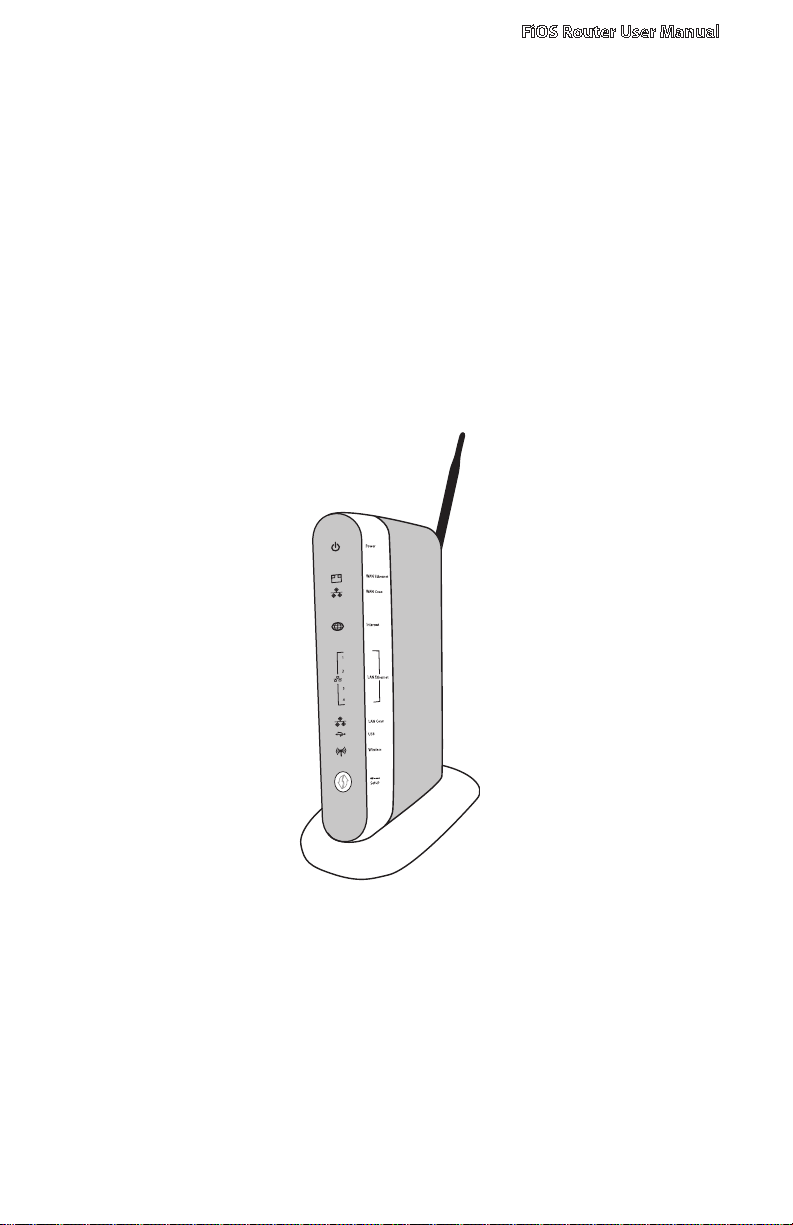
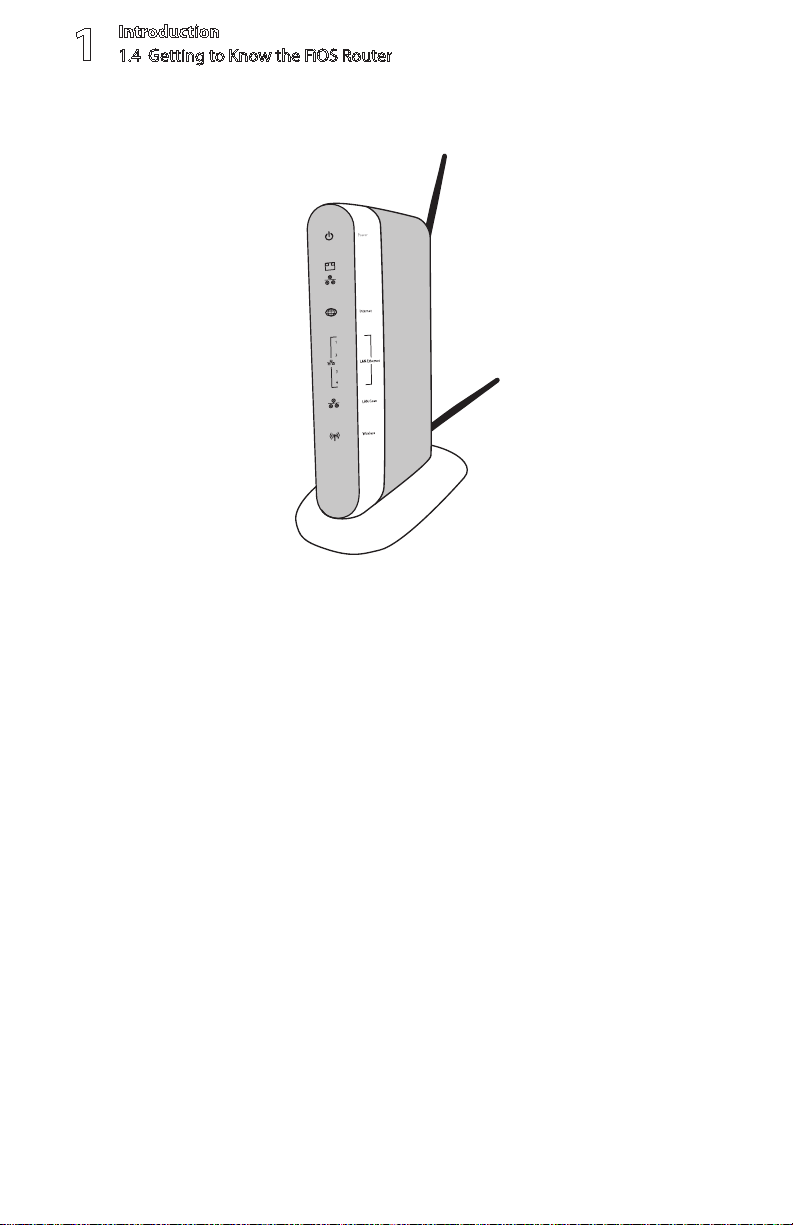
1.4 Getting to Know the FiOS Router
This section contains a quick description of the FiOS Router’s lights (LEDs), ports,
etc. The FiOS Router has several indicator lights on its front panel, and a series of
ports and switches on its rear panel.
1.4a Front Panel
The front panel of the FiOS Router has a series of indicator lights: Power, WAN
Ethernet, WAN Coax, Internet, LAN Ethernet (4), LAN Coax, USB, and Wireless. It
also features a WPS button.
Front view – Verizon FiOS Router (rev. F)
11
© 2009 Verizon. All Rights Reserved.
Page 12
Introduction
1
1.4 Getting to Know the FiOS Router
Front view – Verizon FiOS Router (rev. F2)
Power Light
The Power light displays the FiOS Router’s current status. If the Power light glows
steadily green, the FiOS Router is receiving power and fully operational. When
the Power light flashes rapidly, the FiOS Router is initializing. If the Power light is
not illuminated or glows red when the Power cord is plugged in and the Power
switch is turned on, the FiOS Router has suffered a critical error and technical
support should be contacted.
WAN Ethernet Light
The WAN Ethernet light illuminates when the FiOS Router is connected to the
Internet via Ethernet. If flashing, data traffic is passing across the port.
WAN Coax Light
The WAN Coax light glows steadily or flashes when the FiOS Router is connected
to the Internet via coaxial cable.
Internet Light
12
© 2009 Verizon. All Rights Reserved.
Page 13

FiOS Router User Manual
When the Internet light glows steadily green, the FiOS Router is connected
to the ISP (Internet Service Provider). If it glows amber, there is a physical
connection to the ONT (Optical Network Terminator), but authentication has not
taken place (i.e., no IP address is present).
LAN Ethernet Lights (1, 2, 3, 4)
The LAN Ethernet lights illuminate when the FiOS Router is connected to a local
network via one or more of its Ethernet ports. If flashing, data traffic is passing
across the port(s).
LAN Coax Light
The LAN Coax light glows steadily or flashes when the FiOS Router is connected
to a local network via its Coax port.
USB Light
The USB light illuminates when the FiOS Router is connected to a device via a
USB cable.
Wireless Light
The Wireless light illuminates when the FiOS Router’s wireless access point is
turned on. If flashing, data traffic is passing across the wireless connection.
13
© 2009 Verizon. All Rights Reserved.
Page 14
Introduction
On/O
ff
Coax
1
2
3
4
100
100
100
100
10
10
10
10
LAN
WAN
100
10
Reset
Ethernet Cable
(from LAN Ethernet Port
to Computer/Device)
Ethernet Cable
(from WAN Port
to ISP Connection)
Power Adapter
(from Power Port
to Wall Outlet)
Coaxial Cable
(from Coax Port
to Set Top Box)
USB
USB Cable
(from USB Port
to Device)
1
1.4 Getting to Know the FiOS Router
Wi-Fi Protected Setup
WiFi Protected Setup (WPS) is an easier way to set up a wireless network. Instead
of entering passwords or multiple keys on each wireless client (laptop, printer,
external hard drive, etc.), the FiOS Router can create a wireless network that only
requires the pressing of buttons (one on the FiOS Router, and one on the client
[either built-in, or on a compatible wireless card]) to allow wireless clients to join
the FiOS Router’s wireless network. Although the WPS button is included on
the FiOS Router, WPS functionality will not be enabled until a future firmware
release. The button is included so that WPS can be activated at a later date
without having to physically change the FiOS Router. The GUI does not include
the WPS option.
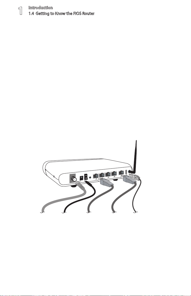
1.4b Rear Panel
The rear panel of the FiOS Router has eight ports (Coax, Power, LAN Ethernet [4],
WAN Ethernet, and USB), a Power switch, a Reset button, and a wireless antenna.
© 2009 Verizon. All Rights Reserved.
Rear view – Verizon FiOS Router (rev. F)
14
Page 15

On/O
ff
Coax
1
2
3
4
100
100
100
100
10
10
10
10
LAN
WA
N
100
10
Reset
Ethernet Cable
(from LAN Ethernet Port
to Computer/Device)
Ethernet Cable
(from WAN Port
to ISP Connection)
Power Adapter
(from Power Port
to Wall Outlet)
Coaxial Cable
(from Coax Port
to Set Top Box)
USB
USB Cable
(from USB Port
to Device)
Coax Port
FiOS Router User Manual
Rear view – Verizon FiOS Router (rev. F2)
The Coax port connects the FiOS Router to the ISP or other devices using a
coaxial cable.
Power Port
The Power port connects the FiOS Router to an electrical wall outlet via the
Power cord.
Power Switch
The Power switch powers the FiOS Router on and off.
15
© 2009 Verizon. All Rights Reserved.
Page 16

Introduction
1
1.4 Getting to Know the FiOS Router
Reset Button
To restore the FiOS Router’s factory default settings, press and hold the Reset
button for approximately ten seconds. The reset process will start about ten
seconds after releasing the button. When the FiOS Router resets, all the lights
on the front panel turn off, and then some of the lights start flashing. The FiOS
Router has completed its reset process when the Power light glows steadily
green.
Caution! Do not unplug the Power cord from the FiOS Router during the
reset process. Doing so may result in the loss of the FiOS Router’s configuration
information. If this occurs, reset the FiOS Router again.
LAN Ethernet Ports (4)
The LAN Ethernet ports connect devices to the FiOS Router via Ethernet cables
to create a local area network (LAN). The LAN Ethernet ports are 10/100 Mbps
auto-sensing ports, and either a straight-through or crossover Ethernet cable
can be used when connecting devices to the ports.
WAN Ethernet Port
The WAN Ethernet port connects the FiOS Router to the ISP using an Ethernet cable.
USB Port
The USB port provides up to 5 VDC for attached devices (to charge a cell phone,
for example). In the future, with a firmware release upgrade, the USB host
functionality will be available for devices such as external storage and cameras.
Wireless Antenna(s)
The FiOS Router’s wireless antenna(s) is used to transmit a wireless signal to
other wireless devices on its wireless network.
16
© 2009 Verizon. All Rights Reserved.
Page 17
2.0 Introduction
2.1 Setting up the FiOS Router
2.2 Computer Network
Conguration
2.3 Conguring the FiOS Router
2.4 Main Screen
2
Connecting
the FiOS
Router
17
© 2009 Verizon. All Rights Reserved.
Page 18
Connecting the FiOS Router and accessing
its Graphical User Interface (GUI) are
both simple procedures, varying slightly
depending on the computer’s operating
system. However, no conguration is
necessary to access the GUI when taking
advantage of Universal Plug-and-Play
support.
© 2009 Verizon. All Rights Reserved.
18
Page 19

FiOS Router User Manual
2.1 Setting Up the FiOS Router
There are three parts to setting up the FiOS Router: Connecting the Cables,
Configuring the Router, and Connecting Other Computers/Set Top Boxes.
2.1a Connecting the Cables
Note: If a different router was being used previously, disconnect it. Remove all
router components, including power supplies and cables, as they will not work
with the FiOS Router.
Get the FiOS Router and black Power cord from the box.1.
Plug the black Power cord in the black port on the back of the FiOS Router 2.
and then into a power outlet.
Turn the FiOS Router on.3.
Make sure the Power light on the front of the FiOS Router glows steadily 4.
green.
Plug the yellow Ethernet cable from the box into one of the four yellow 5.
Ethernet ports on the back of the FiOS Router.
Make sure the computer is powered on, then plug the other end of the 6.
yellow Ethernet cable into an Ethernet port on the computer.
Make sure at least one of the Ethernet LAN lights on the front of the FiOS 7.
Router glows steadily green. This may take a few moments.
The phone company previously installed a high-speed wall jack somewhere 8.
in the house. Locate it and note its type (Ethernet or coaxial). If Ethernet,
follow steps 8a and 8b. If coaxial, follow steps 9a and 9b. Then, continue to
step 10.
a. If connecting via Ethernet, get the white Ethernet cable from the box and
plug one end in the white port on the back of the FiOS Router.
b. Plug the other end of the white Ethernet cable into the high-speed
Ethernet jack.
19
© 2009 Verizon. All Rights Reserved.
Page 20

Connecting the FiOS Router
2
2.2 Computer Network Conguration
a.9. If connecting via coaxial cable, get a coaxial cable and connect one end
to the red Coax port on the back of the FiOS Router.
b. Connect the other end of the coaxial cable to a coax jack.
10.
Make sure the Ethernet WAN light (if connecting via Ethernet) or Coax WAN
light (if connecting via coaxial cable) on the front of the FiOS Router glows
steadily green. If connecting via coaxial cable, this may take a few minutes.
Note: If the Ethernet WAN light or Coax WAN light does not illuminate, make
sure the cable (Ethernet or coaxial) is connected properly at both ends.
2.2 Computer Network Configuration
Each network interface on the computer should either be configured with a
statically defined IP address and DNS address, or instructed to automatically
obtain an IP address using the Network DHCP server. The FiOS Router is set up, by
default, with an active DHCP server, and we recommend leaving this setting as is.
2.2a Configuring Dynamic IP Addressing
To set up a computer to use dynamic IP addressing:
Windows Vista
Select 1. Network and Sharing in the Control Panel.
Click 2. View Status, then click Properties.
Click 3. Continue in the “User Account Control” window.
In the “General” tab of the “Local Area Connection Properties” window select 4.
Internet Protocol Version 4 (TCP/IPv4), then click Properties.
The “Internet Protocol Version 4 (TCP/IPv4) Properties” window appears. 5.
Click the “Obtain an IP address automatically” radio button. 6.
Click the “Obtain DNS server address automatically” radio button. 7.
Click 8. OK in the Internet Protocol Version 4(TCP/IPv4) Properties window,
then click OK in the “Local Area Connection Properties” screen to save the
settings.
© 2009 Verizon. All Rights Reserved.
20
Page 21

FiOS Router User Manual
Windows XP
Select 1. Network Connections in the Control Panel.
Right-click 2. Ethernet Local Area Connection, then click Properties.
In the “General” tab, select 3. Internet Protocol (TCP/IP), then click Properties.
The “Internet Protocol (TCP/IP) Properties” window appears. 4.
Click the “Obtain an IP address automatically” radio button. 5.
Click the “Obtain DNS server address automatically” radio button. 6.
Click 7. OK in the “Internet Protocol (TCP/IP) Properties” screen, then click OK in
the “Local Area Connection Properties” screen to save the settings.
Windows 2000
Select 1. Network and Dialing Connections in the Control Panel.
Right-click on the Ethernet connection’s icon, then click 2. Properties.
Select 3. Internet Protocol (TCP/IP) component, then click Properties.
The “Internet Protocol (TCP/IP) Properties” window appears. 4.
Click the “Obtain an IP address automatically” radio button. 5.
Click the “Obtain DNS server address automatically” radio button. 6.
Windows 98/Me
Select 1. Network in the Control Panel.
Select the 2. TCP/IP settings for the network card, then click Properties.
Click the “Obtain an IP address automatically” radio button in the “IP Address” 3.
tab.
Click 4. Disable DNS in the DNS configuration tab.
Click 5. OK in the “TCP/IP Properties” screen.
Click 6. OK in the “Network” screen to reboot and save the settings.
21
© 2009 Verizon. All Rights Reserved.
Page 22

Connecting the FiOS Router
2
2.2 Computer Network Conguration
Windows NT
Click 1. Network in the Control Panel. The “Network” window appears.
In the “Protocol” tab, select 2. Internet Protocol (TCP/IP), then click
Properties.
In the “IP Address” tab, click the “Obtain an IP address automatically” radio 3.
button.
In the “DNS” tab, verify no DNS server is defined in the “DNS Service Search 4.
Order” text box and no suffix is defined in the “Domain Suffix Search Order”
text box.
Macintosh OS X
Click on the Apple icon in the top left corner of the desktop. 1.
From the menu that appears, select 2. System Preferences.
The “System Preferences” window appears. Click 3. Network.
From the “Network” window, make sure “Ethernet” in the list on the left is 4.
highlighted and displays “Connected.”
Click 5. Assist me.
From the tab that appears, click 6. Diagnostics.
Follow the instructions in the “Network Diagnostics” assistant. 7.
Linux
Login into the system as a super-user by entering “su” at the prompt. 1.
Type “ifconfig” to display the network devices and allocated IPs. 2.
Type “pump -i <dev>,” where <dev> is the network device name. 3.
Type “ifconfig” again to view the newly allocated IP address. 4.
Make sure no firewall is active on device <dev>. 5.
© 2009 Verizon. All Rights Reserved.
22
Page 23
FiOS Router User Manual
2.3 Configuring the FiOS Router
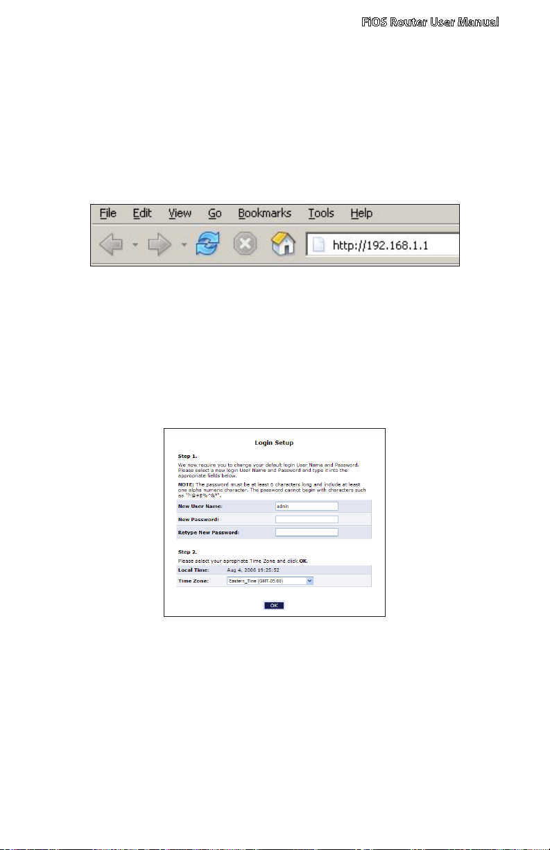
Open a web browser on the computer connected to the FiOS Router. In the 1.
“Address” text box, type:
http://192.168.1.1
then press Enter on the keyboard.
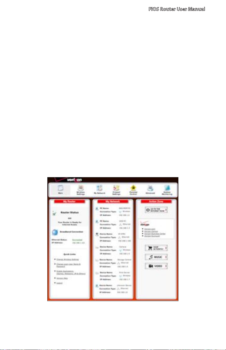
The “Login Setup” screen appears. Select a new user name and password 2.
and enter them in the appropriate text boxes (the password must be
entered twice, for validation purposes). Write the new user name and
password down on a piece of paper and keep it in a safe place, since they
will be needed to access the FiOS Router’s GUI (Graphical User Interface) in
the future.
In the bottom part of the screen, select the correct time zone from the “Time 3.
Zone” drop-down list, then click OK at the bottom of the screen.
The FiOS Router is now configured.
23
© 2009 Verizon. All Rights Reserved.
Page 24

Connecting the FiOS Router
2
2.3 Conguring the FiOS Router
2.3a Connecting Other Computers/Set Top Boxes
The FiOS Router can connect to other computers or set top boxes in three ways:
via Ethernet, via wireless connection, or via coaxial cable.
Ethernet
Get an Ethernet cable and plug one end into one of the open yellow 1.
Ethernet ports on the back of the FiOS Router.
Plug the other end of the Ethernet cable into an Ethernet port on the 2.
computer.
Make sure the corresponding Ethernet LAN light on the front of the FiOS 3.
Router glows steadily green.
Repeat these steps for each computer to be connected to the FiOS Router 4.
via Ethernet.
Wireless
Make sure each computer to be connected wirelessly has built-in wireless or 1.
an attached wireless adapter.
Make sure the computer uses the same ESSID and WEP key as the FiOS 2.
Router by launching the computer’s wireless application
Enter the ESSID and WEP key found on the sticker on the bottom of the 3.
FiOS Router in the computer’s wireless settings and click Save. Make sure to
configure the computer to use 64/40-bit WEP encryption.
Make sure the changes were implemented by surfing the Internet from 4.
the computer.
Repeat these steps for every other computer to be connected to the 5.
FiOS Router wirelessly.
© 2009 Verizon. All Rights Reserved.
24
Page 25
FiOS Router User Manual
Coaxial
Make sure all set top boxes are turned off.1.
Disconnect any adapter currently connected to the coaxial jack in the room 2.
where the FiOS Router is.
Connect one end of the coaxial cable to the coaxial wall jack, and the other 3.
end to the red Coax port on the back of the FiOS Router.
Power up the set top box.4.
Make sure the Coax LAN light on the front of the FiOS Router glows steadily 5.
green. This may take a few minutes. When it does, the set top box is
connected to the FiOS Router.
2.4 Main Screen
After logging into the FiOS Router’s GUI (see “Configuring the FiOS Router” at the
beginning of this chapter), the “Main” screen appears.
25
© 2009 Verizon. All Rights Reserved.
Page 26

Connecting the FiOS Router
2
2.4 Main Screen
The Main screen has a menu occupying the top of the screen. Below that, the
screen is divided into three columns: “My Router,” “My Network,” and
“Action Zone.”
2.4a Menu
The Main screen’s menu contains links to all of the configuration options of
the FiOS Router: Wireless Setup (explained in chapter 4 of this manual), My
Network (chapter 5), Firewall Settings (chapter 6), Parental Controls (chapter
7), Advanced (chapter 8), and System Monitoring (chapter 9).
2.4b My Router
This section displays the status of the FiOS Router’s network and Internet
connection. A green light signifies the FiOS Router is connected; a yellow light
means the FiOS Router is attempting to connect; and a red light signifies the
FiOS Router’s connection is down.
Broadband Connection
The “Broadband Connection” section of the My Router column displays the state
of the FiOS Router’s broadband connection (“Connected” or “Disconnected”) for
the two connection options (“Coax Status” and “Ethernet Status”), and the WAN
IP address of the broadband connection.
Quick Links
The “Quick Links” section of the My Router column contains a list of frequently
accessed settings, including “Change Wireless Settings,” “Change Login User
Name & Password,” “Enable Gaming,” and “Logout.”
2.4c My Network
The “My Network” column of the Main screen displays the connection type,
name, and IP address of all devices connected to the FiOS Router’s network.
The icon associated with the device will be displayed normally (signifying an
active device) or shaded (signifying the device has not been active for at least
60 seconds). The user can also configure the basic settings of each device by
clicking on its icon. These settings are described in more detail in chapter 3.
26
© 2009 Verizon. All Rights Reserved.
Page 27

FiOS Router User Manual
2.4d Action Zone
This column contains links to various Verizon Web sites, and other informational
links. Clicking on the icon above “Go to Internet Now” connects the user to the
home page configured on the user’s web browser.
27
© 2009 Verizon. All Rights Reserved.
Page 28
3.0 Introduction
3.1 Overview
3.2 Connecting a Wireless Client
3.3 Wireless Status
3.4 Basic Security Settings
3.5 Advanced Security Settings
3.6 Setting Up a Wireless Client
3
Setting Up
a Wireless
Network
© 2009 Verizon. All Rights Reserved.
28
Page 29
Wireless networking enables you to free
yourself from wires and plugs, making
your devices more accessible and easier
to use. This chapter explains how to create
a wireless network using the FiOS Router,
including accessing and conguring
wireless security options.
29
© 2009 Verizon. All Rights Reserved.
Page 30

Setting Up a Wireless Network
3
3.1 Overview
3.1 Overview
The FiOS Router provides the user with wireless connectivity over the 802.11b
and g standards (the most common wireless standards). 802.11b has a
maximum data rate of 11 Mbps, while 802.11g has a maximum data rate of 54
Mbps. Both operate in the 2.4 GHz range.
The FiOS Router’s wireless feature is turned on, with wireless security activated,
by default. The level of security is 64/40-bit WEP, with a unique WEP key already
entered. This information is displayed on a sticker located on the bottom of the
FiOS Router.
The FiOS Router integrates multiple layers of security. These include the IEEE
802.1x port-based authentication protocol, RADIUS client, EAP-MD5, EAP-TLS,
EAP-TTLS, EAP-PEAP, Wired Equivalent Privacy (WEP), Wi-Fi Protected Access
(WPA) and firewall and VPN applications.
3.2 Connecting a Wireless Client
To connect a wireless client to the FiOS Router:
Note: The following procedure assumes the FiOS Router’s default wireless
settings are intact. If they have been changed, use the new ESSID and wireless
security settings. For more details, see the “Connecting a Wireless Windows XP
Client” section of this chapter.
In the wireless client’s configuration interface, enter the FiOS Router’s 1.
ESSID (found on a sticker on the bottom of the FiOS Router’s case) in the
appropriate text box or field (this varies depending on the wireless client’s
manufacturer).
Enter the FiOS Router’s WEP key (also found on the sticker on the bottom of 2.
the FiOS Router’s case) in the wireless client’s configuration interface.
Save the changes and exit the wireless client’s configuration interface. The 3.
client should now detect and join the FiOS Router’s wireless network. If not,
check the wireless client’s documentation, or contact its manufacturer.
© 2009 Verizon. All Rights Reserved.
30
Page 31

FiOS Router User Manual
3.3 Wireless Status
Clicking on the “Wireless Settings” icon from the Main screen’s menu generates
the “Wireless Status” screen, which displays the current status of the wireless
connection.
3.3a Radio Enabled
Displays whether the FiOS Router’s wireless radio is active.
3.3b SSID
The SSID (Service Set Identifier) is the network name shared among all devices
on a particular wireless network. The SSID must be identical for all devices
on the wireless network. It is case-sensitive and cannot exceed 32 characters.
Make sure the SSID is the same for all devices to be connected to the wireless
network. The FiOS Router comes from the factory with an SSID already entered
and displayed here. The default SSID can also be found on a sticker on the
bottom of the FiOS Router.
3.3c Channel
Displays the channel to which the wireless connection is currently set. All
devices on the wireless network must be on the same channel to function
correctly.
31
© 2009 Verizon. All Rights Reserved.
Page 32

Setting Up a Wireless Network
3
3.3 Wireless Status
3.3d Security Enabled
Displays what kind of security is active on the wireless connection, and the
security encryption key.
3.3e SSID Broadcast
Displays whether the FiOS Router is broadcasting its SSID. If activated, the SSID
of the FiOS Router’s wireless network is broadcast wirelessly.
3.3f MAC Authentication
Displays whether the FiOS Router is using MAC (Media Access Control) address
authentication to allow wireless devices to join the network.
3.3g Wireless Mode
Displays the types of wireless device that can join the network. Options include
802.11b, 802.11g, or Mixed (allows both 802.11b- and 802.11g-equipped
wireless devices to join the network).
3.3h Packets Received/Sent
Displays the number of packets received and sent since the FiOS Router’s
wireless capability was activated.
© 2009 Verizon. All Rights Reserved.
32
Page 33

FiOS Router User Manual
3.4 Basic Security Settings
To configure the FiOS Router’s wireless network for basic security, select “Basic
Security Settings” from the menu on the left side of any Wireless Settings screen.
The “Basic Security Settings” screen appears.
Click the “On” radio button to activate the FiOS Router’s wireless radio.1.
Enter the name of the wireless network in the “SSID” text box (the SSID name 2.
in the figure above is an example; enter a different name for the SSID).
Select the channel at which the FiOS Router’s wireless radio communicates 3.
by selecting it from the “Channel” drop-down list.
To preserve the channel selection in the event of a FiOS Router power cycle, 4.
click in the box next to “Keep my channel selection during power cycle.”
Click the “WEP” radio button to activate WEP (Wired Equivalent Privacy) 5.
security on the wireless network.
Select a WEP security level from the “select a WEP Key” drop-down list 6.
(options include “64/40 bit” or “128/104 bit”).
33
© 2009 Verizon. All Rights Reserved.
Page 34

Setting Up a Wireless Network
3
3.4 Basic Security Settings
Enter the key code in the “Key Code” text box. Each character must be a 7.
letter from A-F or a number from 0-9. If 64/40 bit was selected in step 5,
enter 10 characters. If 128/104 was selected, enter 26 characters.
Write down the wireless settings displayed on the screen. Other wireless 8.
devices must use these same settings when configuring the device’s wireless
networking scheme to join the FiOS Router’s wireless network.
Click 9. Apply to save the settings.
© 2009 Verizon. All Rights Reserved.
34
Page 35

FiOS Router User Manual
3.5 Advanced Security Settings
To configure the FiOS Router’s advanced wireless network security settings,
select “Advanced Security Settings” from the menu on the left side of any
Wireless Settings screen. The “Advanced Security Settings” screen appears.
3.5a Level 1 (Wireless Security)
This section is used to configure different types of wireless security. Select the
type of wireless security to be applied to the wireless network by clicking the
appropriate radio button, then configure the security settings in the subsequent
screens.
35
© 2009 Verizon. All Rights Reserved.
Page 36

Setting Up a Wireless Network
3
3.5 Advanced Security Settings
WEP
If WEP was selected in the Advanced Security Settings screen, the “WEP Key”
screen appears.
Select the appropriate network authentication level from the drop-down list. 1.
Options include Open System Authentication, Shared Key Authentication, or
Both.
Activate WEP key 1 by clicking the radio button next to “1” on the left side.2.
Select the length of key 1 by selecting “64/40 bit” or “128/104 bit” from the 3.
appropriate drop-down list in the “Key Length” column.
Select the type of key from the appropriate drop-down list in the “Entry 4.
Method” column. If “Hex” is selected, the key must be made up of
hexadecimal digits. If “ASCII” is selected, the key can be made up of any
characters.
Enter the key in the appropriate text box in the “Encryption Key” column. 5.
If 64/40 bit was chosen in step 2, enter 10 characters. If 128/104 bit was
chosen, enter 24 characters. Depending on what option was selected in step
3, enter hexadecimal or ASCII characters.
Click 6. Apply to save changes.
© 2009 Verizon. All Rights Reserved.
36
Page 37

FiOS Router User Manual
802.1x WEP
If 802.1x WEP (Wired Equivalent Privacy) was selected, the “WEP+802.1x Radius
Settings” screen appears. To generate the full screen, click in the “Enabled” check
box to activate.
802.1x WEP is a robust security protocol that uses port control with dynamically
changing encryption keys automatically updated over the network. 802.1x WEP
uses a RADIUS (Remote Authentication Dial-in Service) server for authentication
purposes. This server must be physically connected to the FiOS Router. Also, the
user must enable the RADIUS client embedded in the FiOS Router (to do this,
see chapter 9, “Advanced Settings”).
Click in the “Enabled” check box to enable WEP+802.1x security.1.
Enter the RADIUS server IP address in the “Server IP” text boxes.2.
Enter the RADIUS server’s port number in the “Server Port” text box.3.
Enter the RADIUS server’s shared secret in the “Shared Secret” text box.4.
Click 5. Apply to save changes.
37
© 2009 Verizon. All Rights Reserved.
Page 38

Setting Up a Wireless Network
3
3.5 Advanced Security Settings
WPA
If WPA (Wi-Fi Protected Access) was selected, the “WPA Key” screen appears.
Verify the authentication method selected is “Pre-Shared Key.”1.
Enter a phrase of at least eight characters in the “Pre-Shared Key” text box. 2.
Verify that “ASCII” is selected in the associated drop-down list.
Select the proper encryption algorithm (TKIP or AES). 3.
Click in the “Group Key Update Interval” check box to activate the group key 4.
update interval, and set the interval time in the text box to the right.
Click 5. Apply at the bottom of the screen to save changes.
WPA2
If WPA2 was selected, the “WPA2” screen appears.
Verify the authentication method selected is “Pre-Shared Key.”1.
Enter a phrase of at least eight characters in the “Pre-Shared Key” text box. 2.
Verify that “ASCII” is selected in the associated drop-down list.
Select the proper encryption algorithm (TKIP or AES). 3.
© 2009 Verizon. All Rights Reserved.
38
Page 39

FiOS Router User Manual
Click in the “Group Key Update Interval” check box to activate the group key 4.
update interval, and set the interval time in the text box to the right.
Click 5. Apply at the bottom of the screen to save changes.
3.5b Level 2 (SSID Broadcast)
This section is used to configure the FiOS Router’s SSID broadcast capabilities.
Selecting “SSID Broadcast” generates the “SSID Broadcast” screen.
Click the “Enable” radio button to enable SSID broadcasting. If enabled, the SSID
of the FiOS Router’s wireless network will be broadcast wirelessly. To disable
SSID broadcasting, click the “Disable” radio button.
3.5c Level 3 (Limiting Access)
This option is used to limit access to the FiOS Router’s wireless network.
39
© 2009 Verizon. All Rights Reserved.
Page 40

Setting Up a Wireless Network
3
3.5 Advanced Security Settings
Wireless MAC Authentication
Wireless MAC authentication allows the user to allow or deny access to the
FiOS Router’s wireless network by a particular device’s MAC address. Selecting
“Wireless MAC Authentication” from the Advanced Security Settings screen
generates the “Wireless MAC Authentication” screen.
To set up wireless MAC authentication:
Click in the “Enable Access List” check box.1.
Select either “Accept all devices listed below” or “Deny all devices listed 2.
below” by clicking the appropriate radio button. Selecting “Accept…”
causes all devices listed by MAC address to access the FiOS Router’s wireless
network. Selecting “Deny…” causes all listed devices to be denied access.
Enter the MAC address of a device in the “Client MAC address” text box.3.
Click 4. Add.
Repeat steps 3 and 4 to add more devices to the list.5.
When finished listing devices, click 6. Apply.
To remove a MAC address, select it from the “List” list box, then click Remove.
© 2009 Verizon. All Rights Reserved.
40
Page 41

FiOS Router User Manual
802.11b/g Mode
This option allows the user to select the wireless communication standard
compatible with the devices to be connected on the wireless network from
the drop-down list. Options include 802.11b, 802.11g, or Mixed (allows both
802.11b and 802.11g-equipped wireless devices to join the network).
3.5d Other Advanced Wireless Options
Clicking Other Advanced Wireless Options at the bottom of the Advanced
Security Settings screen generates (after clicking through the “Warning” screen)
another “Advanced Wireless Options” screen.
When should this rule occur?
Displays the time during which the rule is active. To configure schedule rules,
see chapter 8, “Advanced Settings.”
41
© 2009 Verizon. All Rights Reserved.
Page 42

Setting Up a Wireless Network
3
3.5 Advanced Security Settings
Network
Select the type of connection being configured from this drop-down list
(options: Network [Home/Office], Broadband Connection, or DMZ).
MTU
MTU (Maximum Transmission Unit) specifies the largest packet size permitted
for Internet transmission. “Automatic” sets the MTU at 1500. Other choices
include “Automatic by DHCP,” which sets the MTU according to the DHCP
connection, and “Manual,” which allows the user to set the MTU.
Transmission Rate
Select the wireless transmission rate from the drop-down list, or select “Auto” to
have the FiOS Router automatically select the best transmission rate. This setting
adjusts the bit rate of the FiOS Router’s wireless transmissions.
CTS Protection Mode
Activating CTS (Clear to Send) Protection Mode allows mixed 802.11b/g
networks to operate at maximum efficiency. Select Auto from the drop-down
list to activate. Select None to deactivate .
CTS Protection Type
Select from the two options: cts-only (for mixed 802.11b/g networks) or rts-cts.
(for 802.11a/b/g networks).
Frame Burst - Max Number
Frame Burst allows packet bursting, which increases overall network speed.
Enter the maximum number of frame bursts in this text box.
Frame Burst - Burst Time
Enter the burst time of the frame bursts in this text box.
© 2009 Verizon. All Rights Reserved.
42
Page 43

FiOS Router User Manual
DTIM Interval
Enter the DTIM (Delivery Traffic Indication Message) interval value (in
milliseconds) in this text box. A DTIM is a countdown mechanism for the FiOS
Router, informing wireless network clients of the next window for listening to
broadcast and multicast messages.
Fragmentation Threshold
Setting the correct fragmentation threshold can increase the reliability of frame
transmissions on the wireless network. Enter the fragmentation threshold in this
text box.
RTS Threshold
Enter the RTS (Request to Send) threshold in this text box. This setting controls
what size data packet the low level RF protocol issues to an RTS packet.
43
© 2009 Verizon. All Rights Reserved.
Page 44

Setting Up a Wireless Network
3
3.6 Setting Up a Wireless Client
3.6 Setting Up a Wireless Client
If the computer has wireless capabilities and is running Windows XP or
Vista, it will automatically recognize the existing wireless network and try to
create a wireless connection. View this connection under Windows’ “Network
Connections.”
3.6a Joining an Open Wireless Network (Window XP)
Note: The following description and images are in accordance with Microsoft
Windows XP, Version 2002, running Service Pack 2. If running another operating
system, see the documentation that came with the wireless adapter being used.
Click 1. Network Connections in the Control Panel. The “Network
Connections” window appears.
© 2009 Verizon. All Rights Reserved.
44
Page 45

FiOS Router User Manual
Double-click the wireless connection icon. The “Wireless Network 2.
Connection” screen appears, displaying all available wireless networks in the
vicinity. If the FiOS Router is connected and active, the FiOS Router’s wireless
connection is displayed. Note that the connection’s status is “Not connected”
in the figure below.
Click the connection once to mark it, then click 3. Connect at the bottom of
the screen. After clicking throught the “Warning” screen, and establishing
the connection, its status will change to “Connected.”
An icon appears in the notification area, announcing the successful initiation
of the wireless connection.
45
© 2009 Verizon. All Rights Reserved.
Page 46

Setting Up a Wireless Network
3
3.6 Setting Up a Wireless Client
Test the connection by disabling all other connections in the Network 4.
Connections window and browsing the Internet.
The FiOS Router’s wireless network can now be accessed from the configured
computer. However, any other user with a wireless-equipped device can also
access the wireless network. To prevent this, secure the wireless network, as
explained in the “Wireless Security” section of this chapter.
3.6b Joining a Secured Wireless Network (Windows XP)
This section assumes the FiOS Router’s wireless network is set up with 64-bit
WEP security.
Click 1. Network Connections in the Control Panel. The “Network
Connections” window appears.
© 2009 Verizon. All Rights Reserved.
46
Page 47

FiOS Router User Manual
Double-click the wireless connection icon. The “Wireless Network 2.
Connection” screen appears, displaying the available wireless connections.
Select the FiOS Router’s network.
Click the connection once to mark it, then click 3. Connect at the bottom of
the screen. The following login window appears, asking for a “Network Key,”
which is the pre-shared key used when configuring the FiOS Router’s WEP
security (see the “WEP” section in this chapter).
47
© 2009 Verizon. All Rights Reserved.
Page 48

Setting Up a Wireless Network
3
3.6 Setting Up a Wireless Client
Enter the network (WEP) key in both text boxes and click 4. Connect. After the
connection is established, its status will change to “Connected,” as shown
below.
An icon appears in the notification area, announcing the successful initiation
of the wireless connection.
Test the connection by disabling all other connections in the Network 5.
Connections window and surfing the Internet.
Manual Wireless Network Connection
If the login window shown in step 3 does not appear and the connection
attempt fails, configure the connection manually using the following procedure:
Click the connection once to mark it and then click 1. Change Advanced
Settings in the “Related Tasks” box on the left part of the window.
© 2009 Verizon. All Rights Reserved.
48
Page 49

FiOS Router User Manual
The “Wireless Network Connection Properties” window appears. Select 2.
Wireless Networks.
Click the connection to highlight it, then click 3. Properties. The connection’s
“Properties Window” appears.
49
© 2009 Verizon. All Rights Reserved.
Page 50

Setting Up a Wireless Network
3
3.6 Setting Up a Wireless Client
From the “Network Authentication” drop-down list, select “Open.”4.
From the “Data Encryption” drop-down list, select “WEP.”5.
Enter the pre-shared key in both the “Network key” and the “Confirm 6.
network key” text boxes.
Click 7. OK, then OK again.
When attempting to connect to the wireless network, the login window 8.
appears, pre-populated with the pre-shared key. Press Connect to connect.
Since the network is now secured, only users who know the pre-shared key will
be able to connect.
3.6c Setting Up a Wireless Windows Client (Vista)
If the computer has wireless capabilities and is running Windows Vista, it will
automatically recognize the existing wireless network and try to create a wireless
connection. View this connection under Windows’ “Network Connections.”
Click the wireless icon the system tray (in the lower right corner of the 1.
desktop) and, from the menu that appears, select Connect to a Network.
A “Connect to a Network” window appears. Select the FiOS Router’s 2.
wireless network.
© 2009 Verizon. All Rights Reserved.
50
Page 51

FiOS Router User Manual
Another Connect to a Network window appears. Enter the WEP key of the 3.
network in the appropriate text box.
Click 4. Connect. A third Connect to a Network window appears, stating that
the connection was successful
51
© 2009 Verizon. All Rights Reserved.
Page 52

4.0 Introduction
4.1 Accessing the My Network
Settings
4.2 Using the My Network
Settings
4
Conguring
My Network
Settings
© 2009 Verizon. All Rights Reserved.
52
Page 53

Once the FiOS Router is physically
connected and the FiOS Router’s Main
screen is displayed in a web browser, a list
of devices connected to the FiOS Router’s
network appears in the “My Network”
column of the screen. From here, some
basic network settings can be congured.
53
© 2009 Verizon. All Rights Reserved.
Page 54

Conguring My Network Settings
4
4.1 Accessing My Network Settings
4.1 Accessing My Network Settings
To access My Network, click the “My Network” icon in the Main screen.
The “My Network” screen appears:
On the far right side of the screen, in the “Connected Devices” section, is list
of the devices currently connected to the FiOS Router’s network, listed by
connection type and number. The rest of the screen contains the “My Network”
section, which displays each device connected to the FiOS Router’s network,
and a series of basic configuration settings for each device.
© 2009 Verizon. All Rights Reserved.
54
Page 55

FiOS Router User Manual
4.2 Using My Network Settings
Various settings can be accessed for a particular device, as follows.
4.2a Access Device
For devices that can be accessed (such as Internet cameras and networked hard
drives), locate it in the My Network column, then click Access Devices to use
the device over the network.
4.2b Access Shared Files
To access the shared files on a particular device, locate the device in the My
Network column, then click Access Shared Files. A list of shared files appears
on the screen.
4.2c Website Blocking
Clicking Website Blocking generates the “Parental Control” screen. For more
information about using parental controls, see chapter 7, “Using Parental
Controls.”
4.2d Block Internet Services
Internet services blocking is used to prevent a device on the network from
accessing particular services available on the Internet, such as receiving email
or downloading files from FTP sites. To set up Internet services blocking on a
networked device:
Locate the device in the My Network column, then click
1. Block Internet
Services. The “Access Control” screen appears.
55
© 2009 Verizon. All Rights Reserved.
Page 56

Conguring My Network Settings
4
4.2 Using My Network Settings
Click 2. Add in the “Networked computer/Device” column. The “Add Access
Control Rule” screen appears.
If this access control rule applies to all networked devices, select “Any” from 3.
the “Networked Computer/Device” list box. If this rule applies to certain
devices only, select “User Defined” and click Add. Then, in the “Edit Network
Object” screen, add a network object (for more details about adding
network objects, see the “Advanced Settings” chapter of this manual).
Select the Internet protocol to be blocked from the “Protocol” drop-down 4.
list.
If this rule will be active continuously, select 5. Always from the “When should
this rule occur?” drop-down list. If the rule will only be active at certain times,
select “User Defined” and click Add. Then, add a schedule rule (for more
details about schedule rules, see the “Advanced Settings” chapter of
this manual).
Note: Make sure the FiOS Router’s date and time settings for your time zone are
set correctly for schedule rules to function properly.
Click 6. Apply to save the changes. The Access Control screen will display a
summary of the access control rule.
Note: To block a service that is not included in the list, select “User Defined”
from the Protocol drop-down menu. The “Edit Service” screen appears. Define
the service, then click Apply. The service will then be automatically added to the
© 2009 Verizon. All Rights Reserved.
56
Page 57

FiOS Router User Manual
top section of the “Add Access Control Rule” screen, and will be selectable.
The user may disable an access control and the service made available without
having to remove the service from the Access Control table. This may be useful
to make the service available only temporarily, with the expectation that the
restriction will be reinstated later.
To temporarily disable an access control, clear the check box next to the t
network computer/device.
To reinstate the restriction at a later time, select the check box next to the t
network computer/device.
To remove an access restriction from the Access Control table, click t Remove
for the service. The service will be removed from the Access Control table.
Note: When Web Filtering is enabled, HTTP services cannot be blocked by
access control.
4.2e Port Forwarding
Activating “Port Forwarding” allows the network to be exposed to the Internet
in certain limited and controlled ways, enabling some applications to work from
the local network (game, voice, and chat applications, for example), as well
as allowing Internet access to servers in the local network. To set this up on a
networked device, locate the device in the My Network column, then click Port
Forwarding. The “Port Forwarding” screen appears.
57
© 2009 Verizon. All Rights Reserved.
Page 58

Conguring My Network Settings
4
4.2 Using My Network Settings
To set up basic port forwarding:
Click the arrow next to “IP Address forward to or select from menu” to 1.
display a menu and either enter the IP address of the item to port forward
from, or choose an item from the drop-down menu.
Click the arrow next to “Application to forward…” and select a pre-
2.
configured application from the drop-down menu.
Click 3. Add. The new port forwarding rule appears in the “Applied rules” table
at the bottom of the screen.
To set up advanced port forwarding (custom ports):
Click the arrow next to “Application to forward…” and select 1. Custom Ports
from the drop-down menu.
Enter the host name (from the drop-down list) or local IP address of the 2.
computer providing the service in the “Specify IP” text box. Note that only
one local network computer can be assigned to provide a specific service
or application.
Click 3. Advanced.
4.
Select the Internet protocol to be provided from the “Protocol” drop-down
list. Depending on the protocol selected, additional options appear in
the screen.
Select the connection with which this port forwarding rule will be active 5.
© 2009 Verizon. All Rights Reserved.
58
Page 59

FiOS Router User Manual
from the “WAN Connection Type” drop-down list.
To select a port to forward communications to (this is optional), select 6.
“Specify” from the “Forward to Port” drop-down list, then, in the text box
that appears, enter the port number. If no port is identified, select “Same as
Incoming Port.”
If this port will be active all the time, select “Always” from the “Schedule” 7.
drop-down list. If the rule will only be active at certain times, select “User
Defined” and click Add. Then, add a schedule rule (for more details about
schedule rules, see the “Advanced Settings” chapter of this manual).
If source and destination ports need to be specified, select Specify from the 8.
drop-down menu list (by clicking on the appropriate arrow), then entering
the port numbers.
Click 9. Apply to save the changes. The new port forwarding rule appears in
the “Applied rules” table at the bottom of the screen.
Note: Some applications, such as FTP, TFTP, PPTP, and H323, require the support
of special specific Application Level Gateway (ALG) modules to work inside the
local network. Data packets associated with the aforementioned applications
contain information that allows them to be routed correctly. An ALG is needed
to handle these packets and ensure they reach their intended destinations. The
FiOS Router is equipped with a robust list of ALG modules, enabling maximum
functionality in the local network. The ALG is automatically assigned based on
the destination port.
4.2f View Device Details
To view information about a networked device, or to test a device’s connection,
locate the device in the My Network column, then click View Device Details.
The “Device Information” screen appears.
59
© 2009 Verizon. All Rights Reserved.
Page 60

Conguring My Network Settings
4
4.2 Using My Network Settings
Click 1. Test Connectivity. The “Diagnostics” screen appears.
The FiOS Router automatically runs a ping test, and the results are displayed 2.
in the Diagnostics screen.
4.2g Rename This Device
To rename a networked device, locate the device in the My Network column,
then click Rename This Device. The “Rename Device” screen appears.
Enter the new name of the device in the “New Name” text box and, if needed,
select a new icon for the device from the “New Icon” drop-down list.
© 2009 Verizon. All Rights Reserved.
60
Page 61

5
Using
5.0 Introduction
5.1 Accessing Network
Connections
5.2 Network (Home/Oce)
Connection
5.3 Ethernet Connection
5.4 Wireless Access Point
Connection
5.5 Coax Connection
5.6 Broadband Ethernet
Connection
5.7 Broadband Coax Connection
5.8 WAN PPPoE Connection
5.9 WAN PPPoE 2 Connection
Network
Connections
61
© 2009 Verizon. All Rights Reserved.
Page 62

The FiOS Router supports various local
area network (LAN) and wide area network
(WAN, or Internet) connections via
Ethernet or coaxial cables. The “Network
Connections” screens are used to congure
the various aspects of the FiOS Router’s
network and Internet connections, and
create new connections.
© 2009 Verizon. All Rights Reserved.
62
Page 63

FiOS Router User Manual
5.1 Accessing Network Connections
Caution! The settings covered in this chapter should be configured by
experienced network technicians only.
To access the FiOS Router’s network connections, in the “My Network” screen,
click Network Connections from the menu on the left side. The “Network
Connections” screen appears.
Click Advanced to expand the screen and display all connection entries.
To select a connection, click on its name. The rest of this chapter describes
the different network connections available on the FiOS Router, as well as the
connection types that can be created.
63
© 2009 Verizon. All Rights Reserved.
Page 64

Using Network Connections
5
5.2 Network (Home/Oce) Connection
5.2 Network (Home/Office) Connection
Select Network (Home/Office) in the Network Connections screen to generate
the “Network (Home/Office) Properties” screen. This screen displays a list of
the local network’s properties. The only modifications that can be made from
this screen are disabling the connection (by clicking Disable) or renaming the
connection (by entering a new name in the “Rule Name” text box).
Note: When a network is disabled, its formerly underlying devices will not be
able to get the DHCP address from the network interface to which they were
connected.
The Network (Home/Office) connection is used to combine several network
devices under one virtual network. For example, a home/office network can be
created for Ethernet and other network devices.
64
© 2009 Verizon. All Rights Reserved.
Page 65

FiOS Router User Manual
5.2a Configuring the Home/Office Network
Click Settings in the “Network (Home/Office) Properties” screen to generate a
second “Network (Home/Office) Properties” screen.
General
The top part of the screen displays general communication parameters. We
recommend not changing the default values in this section unless familiar with
networking concepts.
Status Displays the connection status of the network.
When should this rule occur? Displays when the rule is active. To schedule
rules, see the “Advanced Settings” chapter.
Network Select the type of connection being configured from the drop-down
list (options: Broadband Connection, Network [Home/Office], or DMZ).
Connection Type Displays the type of connection.
Physical Address Displays the physical address of the network card used for
the network.
MTU MTU (Maximum Transmission Unit) specifies the largest packet size
permitted for Internet transmission. “Automatic” sets the MTU at 1500. Other
choices include “Automatic by DHCP,” which sets the MTU according to the DHCP
connection, and “Manual,” which allows the MTU to be set manually.
65
© 2009 Verizon. All Rights Reserved.
Page 66

Using Network Connections
5
5.2 Network (Home/Oce) Connection
Internet Protocol
This section has three options: No IP Address, Obtain an IP Address
Automatically, and Use the Following IP Address.
No IP Address Select this option if the connection will have no IP address. This
is useful if the connection operates under a bridge.
Obtain an IP Address Automatically Select this option if the network
connection is required by the ISP to obtain an IP address automatically. The
server assigning the IP address also assigns a subnet mask address, which can
be overridden by entering another subnet mask address.
Use the Following IP Address Select this option if the network connection
uses a permanent (static) IP address, then the IP address and subnet mask
address.
Bridge
The “Bridge” section of the Configure Network (Home/Office) screen is used to
specify which networks can join the network bridge. Verizon does not support
using the FiOS Router in Bridge mode. Using Bridge mode may cause problems
with the FiOS Router, including the complete disabling of all video services used
with the FiOS Router.
Status The “Status” column displays the connection status of a particular device.
STP Click in the device’s “STP” check box to enable Spanning Tree Protocol
on the device. This protocol provides path redundancy while preventing
undesirable loops in the network.
Action The “Action” column contains an icon that, when clicked, generates the
configuration screen of the particular device.
66
© 2009 Verizon. All Rights Reserved.
Page 67

FiOS Router User Manual
DNS Server
Domain Name System (DNS) is the method by which website or domain names
are translated into IP addresses. Specify such an address manually, according to
the information provided by the ISP.
To manually configure DNS server addresses, select Use the Following DNS
Server Addresses. Specify up to two different DNS server addresses, one
primary, the other secondary.
IP Address Distribution
The “IP Address Distribution” section of the Configure Network (Home/Office)
screen is used to configure the FiOS Router’s Dynamic Host Configuration
Protocol (DHCP) server parameters. DHCP automatically assigns IP addresses
to network devices. If enabled, make sure to configure the network devices as
“DHCP Clients.” There are three options in this section: Disabled, DHCP Server,
and DHCP Relay.
Disabled Select this option if statically assigning IP addresses to the network
devices.
DHCP Server To set up the network bridge to function as a DHCP server:
Select 1. DHCP Server.
Enter the IP address at which the FiOS Router starts issuing addresses in the 2.
“Start IP Address” text boxes. Since the FiOS Router’s default IP address is
192.168.1.1, the Start IP Address should be 192.168.1.2.
Enter the end of the IP address range used to automatically issue IP 3.
addresses in the “End IP Address” text boxes. The “maximum” IP address that
can be entered here is 192.168.1.254.
Enter the subnet mask address in the “Subnet Mask” text boxes. The subnet 4.
mask determines which portion of a destination LAN IP address is the
network portion, and which portion is the host portion.
67
© 2009 Verizon. All Rights Reserved.
Page 68

Using Network Connections
5
5.2 Network (Home/Oce) Connection
If Windows Internet Naming Service (WINS) is being used, enter the WINS 5.
server address in the “WINS Server” text boxes.
Enter the amount of time a network device will be allowed to connect to the
6.
FiOS Router with its currently issued dynamic IP address in the “Lease Time
in Minutes” text box.
Click in the “Provide Host Name If Not Specified by Client” check box to have 7.
the FiOS Router automatically assign network devices with a host name, in
case a host name is not provided by the user.
DHCP Relay Select this option to have the FiOS Router function as a DHCP
relay, and enter the IP address in the screen that appears.
Routing
The FiOS Router can be configured to use static or dynamic routing. Dynamic
routing automatically adjusts how packets travel on the network, while static
routing specifies a fixed routing path to neighboring destinations. To configure
routing:
Enter a device metric in the “Device Metric” text box. The device metric is a 1.
value used by the FiOS Router to determine whether one route is superior to
another, considering parameters such as bandwidth and delay time.
Click in the “Default Route” check box to define this device as a 2.
default route.
Click in the “Multicast - IGMP Proxy Internal” check box to activate 3.
multicasting. Multicasting enables the FiOS Router to issue IGMP (Internet
Group Management Protocol) host messages on behalf of hosts the FiOS
Router discovers through standard IGMP interfaces. IGMP proxy enables the
routing of multicast packets according to the IGMP requests of local network
devices asking to join multicast groups.
© 2009 Verizon. All Rights Reserved.
68
Page 69

FiOS Router User Manual
Routing Table
Clicking New Route generates the “New Route” window, where a new route can
be configured.
Additional IP Addresses
Clicking New IP Address generates the “Additional IP Address Settings” screen,
where additional IP addresses can be created to access the FiOS Router via the
Network (Home/Office) connection.
5.3 Ethernet Connection
An Ethernet connection connects computers to the FiOS Router using Ethernet
cables, either directly or via network hubs and switches. Click Ethernet in the
Network Connections screen (if needed, click Advanced at the bottom of the
screen to reveal the “Ethernet” link below “Network [Home/Office]”) to generate
the “Ethernet Properties” screen. This screen displays a list of the connection’s
properties. The only modifications that can be made from this screen are
disabling the connection (by clicking Disable) or renaming the connection (by
entering a new name in the “Rule Name” text box).
Note: If disabling the connection, the FiOS Router must be rebooted for the
change to take effect.
69
© 2009 Verizon. All Rights Reserved.
Page 70

Using Network Connections
5
5.3 Ethernet Connection
5.3a Configuring the Ethernet Connection
Click Settings at the bottom-right of the Ethernet Properties screen to generate
another “Ethernet Properties” screen.
General
The top part of the screen displays general communication parameters. We
recommend not changing the default values in this section unless familiar with
networking concepts.
Status Displays the connection status of the Ethernet switch.
When should this rule occur? Displays when the rule is active. To schedule
rules, see the “Advanced Settings” chapter.
Network Select the type of connection being configured from the drop-down
list (Network [Home/Office], Broadband Connection, or DMZ).
Connection Type Displays the type of connection.
Physical Address Displays the physical address of the network card used for
the network.
70
© 2009 Verizon. All Rights Reserved.
Page 71

FiOS Router User Manual
MTU MTU (Maximum Transmission Unit) specifies the largest packet size
permitted for Internet transmission. “Automatic” sets the MTU at 1500. Other
choices include “Automatic by DHCP,” which sets the MTU according to the DHCP
connection, and “Manual,” which allows the MTU to be set manually.
Additional IP Addresses
Clicking New IP Address generates the “Additional IP Address Settings” screen,
where additional IP addresses can be created to access the FiOS Router via the
Ethernet connection.
HW Switch Ports
This section displays the connection status of the FiOS Router’s four Ethernet
ports.
Clicking on a connection’s “Action” icon (in the column on the right) generates
the “Port Settings” screen, where ingress and egress policies can be edited.
71
© 2009 Verizon. All Rights Reserved.
Page 72

Using Network Connections
5
5.4 Wireless Access Point Connection
5.4 Wireless Access Point Connection
A Wireless Access Point connection connects devices wirelessly. Click Wireless
Access Point in the Network Connections screen (if needed, click Advanced
at the bottom of the screen to reveal the “Wireless Access Point” link below
“Network [Home/Office]”) to generate the “Wireless Access Point Properties”
screen. This screen displays a list of the connection’s properties. The only
modifications that can be made from this screen are disabling the connection
(by clicking Disable) or renaming the connection (by entering a new name in
the “Name” text box).
Note: If disabling the connection, the FiOS Router must be rebooted for the
change to take effect.
5.4a Configure Wireless Access Point
Click Settings at the bottom-right of the Wireless Access Point Properties screen
generates a second “Wireless Access Point Properties” screen.
72
© 2009 Verizon. All Rights Reserved.
Page 73

FiOS Router User Manual
General
The top part of the screen displays general communication parameters. We
recommend not changing the default values in this section unless familiar with
networking concepts.
Status Displays the status of the wireless access point connection.
When should this rule occur? Displays when the rule is active. To schedule
rules, see the “Advanced Settings” chapter.
Network Select the type of connection being configured from the drop-down
list (options: Network [Home/Office], Broadband Connection, or DMZ).
Connection Type Displays the type of connection.
Physical Address Displays the physical address of the network card used for
the network.
MTU MTU (Maximum Transmission Unit) specifies the largest packet size
permitted for Internet transmission. “Automatic” sets the MTU at 1500. Other
choices include “Automatic by DHCP,” which sets the MTU according to the DHCP
connection, and “Manual,” which allows the MTU to be set manually.
Additional IP Addresses
Clicking New IP Address generates the “Additional IP Address Settings” screen,
where additional IP addresses can be created to access the FiOS Router via the
Wireless Access Point connection.
73
© 2009 Verizon. All Rights Reserved.
Page 74

Using Network Connections
5
5.5 Coax Connection
5.5 Coax Connection
A Coax connection connects devices (such as set-top boxes) to the FiOS Router
using a coaxial cable. Click Coax in the Network Connections screen (if needed,
click Advanced at the bottom of the screen to reveal the “Coax” link below
“Network [Home/Office]”) to generate the “Coax Properties” screen. This screen
displays a list of the connection’s properties. The only modifications that can
be made from this screen are disabling the connection (by clicking Disable) or
renaming the connection (by entering a new name in the “Name” text box).
Note: If disabling the connection, the FiOS Router must be rebooted for the
change to take effect.
5.5a Configure Coax
Click Settings at the bottom-right of the Coax Properties screen generates a
second “Coax Properties” screen.
74
© 2009 Verizon. All Rights Reserved.
Page 75

FiOS Router User Manual
General
The top part of the screen displays general communication parameters. We
recommend not changing the default values in this section unless familiar with
networking concepts.
Status Displays the status of the coax connection.
When should this rule occur? Displays when the rule is active. To schedule
rules, see the “Advanced Settings” chapter.
Network Select the type of connection being configured from the drop-down
list (options: Network [Home/Office], Broadband Connection, or DMZ).
Connection Type Displays the type of connection.
Physical Address Displays the physical address of the network card used for
the network.
MTU MTU (Maximum Transmission Unit) specifies the largest packet size
permitted for Internet transmission. “Automatic” sets the MTU at 1500. Other
choices include “Automatic by DHCP,” which sets the MTU according to the DHCP
connection, and “Manual,” which allows the MTU to be set manually.
Coax Link
Set up the coax link options in this section of the Configure Coax screen.
Options include Channel, Privacy, and Password.
Channel Select the Channel from the drop-down list (select from 1-6, or
“Automatic”).
Privacy Toggle “Privacy” by clicking in the “Enabled” check box. If Privacy is
activated, all devices connected via coaxial cable must use the same password.
We recommend leaving the Privacy option deactivated.
Password Enter the Coax Link password in this text box.
CM Ratio Select the CM Ratio from the drop-down menu here.
75
© 2009 Verizon. All Rights Reserved.
Page 76

Using Network Connections
5
5.5 Coax Connection
Additional IP Addresses
Clicking New IP Address generates the “Additional IP Address Settings” screen,
where additional IP addresses can be created to access the FiOS Router via the
Coax Link Ethernet connection.
Coax Connection Status
Click Go to LAN Coax Stats to generate the “Coax Connection Status” screen,
which gives an overview of all the devices connected to the FiOS Router via
coaxial cable.
© 2009 Verizon. All Rights Reserved.
76
Page 77

FiOS Router User Manual
5.6 Broadband Ethernet Connection
A Broadband Ethernet connection connects the FiOS Router to the Internet
using an Ethernet cable. Click Broadband Connection (Ethernet) from the
Network Connections screen to generate the “Broadband Connection (Ethernet)
Properties” screen. This screen displays a list of the connection’s properties.
The only modifications that can be made from this screen are disabling the
connection (by clicking Disable) or renaming the connection (by entering a
new name in the “Rule Name” text box).
Note: If disabling the connection, the FiOS Router must be rebooted for the
change to take effect.
77
© 2009 Verizon. All Rights Reserved.
Page 78

Using Network Connections
5
5.6 Broadband Ethernet Connection
5.6a Configuring the Broadband Ethernet Connection
Click Settings at the bottom-right of the first Broadband Connection (Ethernet)
Properties window to generate another “Broadband Connection (Ethernet)
Properties” screen.
General
The top part of the screen displays general communication parameters. We
recommend not changing the default values in this section unless you are
familiar with networking concepts.
Status Displays the status of the Ethernet connection (“Down,” “Connected,”
etc.)
Schedule Displays when the rule is active. To configure rules, see the “Advanced
Settings” chapter.
Network Select the type of connection being configured from the drop-down
list (options: Network [Home/Office], Broadband Connection, or DMZ).
78
© 2009 Verizon. All Rights Reserved.
Page 79

FiOS Router User Manual
Connection Type Displays the type of connection. Since this is an Ethernet
Connection, “Ethernet” is displayed.
Physical Address Displays the physical address of the network card used for
the network.
MTU MTU (Maximum Transmission Unit) specifies the largest packet size
permitted for Internet transmission. “Automatic” sets the MTU at 1500. Other
choices include “Automatic by DHCP,” which sets the MTU according to the DHCP
connection, and “Manual,” which allows the MTU to be set manually.
Internet Protocol
This section includes three options: No IP Address, Obtain an IP Address
Automatically, and Use the Following IP Address.
No IP Address Select this option if the connection has no IP address. This is
useful if the connection is operating under a bridge.
Obtain an IP Address Automatically Select this option if the ISP requires
the connection to obtain an IP address automatically. The server assigning the
IP address also assigns a subnet mask address, which can be overridden by
clicking in the “Override Subnet Mask” check box and entering another subnet
mask address. Additionally, the DHCP lease can be renewed and/or released by
clicking on the appropriate “DHCP Lease” button. The “Expires In” value displays
how long until the DHCP lease expires.
Use the Following IP Address Select this option if the connection uses a
permanent (static) IP address. The ISP should provide this address, along with
a subnet mask address, default gateway address, and, optionally, primary and
secondary DNS server addresses.
DNS Server
The Domain Name System (DNS) is the method by which website or domain
names are translated into IP addresses. This connection can be configured
to automatically obtain a DNS server address, or an address can be specified
manually, according to the information provided by the ISP.
To configure the connection to automatically obtain a DNS server address, select
Obtain DNS Server Address Automatically from the “DNS Server” drop-down
list. To manually configure DNS server addresses, select Use the Following
DNS Server Addresses. Specify up to two different DNS server addresses, one
primary, the other secondary.
79
© 2009 Verizon. All Rights Reserved.
Page 80

Using Network Connections
5
5.6 Broadband Ethernet Connection
IP Address Distribution
The “IP Address Distribution” section of the Configure Broadband Connection
(Ethernet) screen is used to configure the FiOS Router’s Dynamic Host
Configuration Protocol (DHCP) server parameters. DHCP automatically assigns
IP addresses to network devices. If enabled, make sure to configure the network
devices as “DHCP Clients.” There are three options in this section: Disabled,
DHCP Server, and DHCP Relay.
Caution! We strongly recommend leaving this setting at “Disabled.”
Disabled Select this option if statically assigning IP addresses to the
network devices.
DHCP Server To set up the FiOS Router to function as a DHCP server:
Select 1. DHCP Server.
Enter the IP address at which the FiOS Router starts issuing addresses in the 2.
“Start IP Address” text boxes. Since the FiOS Router’s default IP address is
192.168.1.1, the Start IP Address must be 192.168.1.2 or higher.
Enter the end of the IP address range used to automatically issue IP 3.
addresses in the “End IP Address” text boxes. The “maximum” IP address that
can be entered here is 192.168.1.254.
Enter the subnet mask address in the “Subnet Mask” text boxes. The subnet 4.
mask determines which portion of a destination LAN IP address is the
network portion, and which portion is the host portion.
If a Windows Internet Naming Service (WINS) is being used, enter the WINS 5.
server address in the “WINS Server” text boxes.
Enter the amount of time a network device will be allowed to connect to the 6.
FiOS Router with its currently issued dynamic IP address in the “Lease Time
in Minutes” text box. Just before the time is up, the device’s user will need to
make a request to extend the lease or get a new IP address.
Click in the “Provide Host Name If Not Specified by Client” check box to have 7.
the FiOS Router automatically assign network devices with a host name, in
case a host name is not provided by the user.
© 2009 Verizon. All Rights Reserved.
80
Page 81

FiOS Router User Manual
DHCP Relay Select this option to have the FiOS Router function as a DHCP
relay. To enter a new IP address for the relay, click New IP Address. The
“DHCP Relay Server Address” screen appears. Enter the new IP address in the
appropriate text boxes, then click Apply.
Routing
Routing Mode Select one of the following two Routing modes:
Routet - Select this option to cause the FiOS Router to act as a router between
two networks.
NAPTt - Select this option to activate NAPT (Network Address and Port
Translation), which refers to network address translation involving the
mapping of port numbers and allows multiple machines to share a single IP
address. Use NAPT if the local network contains multiple devices, a topology
that necessitates port translation in addition to address translation.
Device Metric The device metric is a value used by the FiOS Router to
determine whether one route is superior to another, considering parameters
such as bandwidth, delay, and more.
Default Route Click in this check box to define the connection as a the default
route.
Multicast - IGMP Proxy Default Click in this check box to enable the FiOS
Router to issue IGMP (Internet Group Management Protocol) host messages
on behalf of hosts the FiOS Router discovers through standard IGMP interfaces.
IGMP proxy enables the routing of multicast packets according to the IGMP
requests of local network devices asking to join multicast groups.
Routing Table
Clicking New Route generates the “New Route” window, where a new route can
be configured.
81
© 2009 Verizon. All Rights Reserved.
Page 82

Using Network Connections
5
5.7 Broadband Coax Connection
Internet Connection Firewall
Click in the “Enabled” check box to activate the FiOS Router’s firewall on the
connection.
Additional IP Addresses
Clicking New IP Address generates the “Additional IP Address Settings” screen,
where additional IP addresses can be created to access the FiOS Router via the
connection.
5.7 Broadband Coax Connection
A Broadband Coax connection connects the FiOS Router to the Internet using a
coaxial cable. Click Broadband Connection (Coax) in the Network Connections
screen to generate the “Broadband Connection (Coax) Properties” screen. This
screen displays a list of the connection’s properties. The only modifications that
can be made from this screen are disabling the connection (by clicking Disable)
or renaming the connection (by entering a new name in the “Name” text box).
Note: If disabling the connection, the FiOS Router must be rebooted for the
change to take effect.
82
© 2009 Verizon. All Rights Reserved.
Page 83

FiOS Router User Manual
5.7a Configuring the Broadband Coax Connection
Click Settings at the bottom of the Broadband Connection (Coax) Properties
screen to generate another “Broadband Connection (Coax ) Properties” screen.
General
The top part of the screen displays general communication parameters. We
recommend not changing the default values in this section unless you are
familiar with networking concepts.
Status Displays the status of the connection (“Down,” “Connected,” etc.).
When should this rule occur? Displays when the rule is active. To schedule
rules, see the “Advanced Settings” chapter.
Network Select the type of connection being configured from the drop-down
list (options: Network [Home/Office], Broadband Connection, or DMZ).
83
© 2009 Verizon. All Rights Reserved.
Page 84

Using Network Connections
5
5.7 Broadband Coax Connection
Connection Type Displays the type of connection. Since this is a coaxial
connection, “Coax” is displayed.
Physical Address Displays the physical address of the network card used for
the network.
MTU MTU (Maximum Transmission Unit) specifies the largest packet size
permitted for Internet transmission. “Automatic” sets the MTU at 1500. Other
choices include “Automatic by DHCP,” which sets the MTU according to the DHCP
connection, and “Manual,” which allows the MTU to be set manually.
Coax Link
Check and configure the coax link connection in this section of the screen.
Auto Detection Select whether you want the FiOS Router to automatically
detect a coaxial link here.
Privacy Toggle “Privacy” by clicking in the “Enabled” check box. If Privacy is
activated, all devices connected via coaxial cable must use the same password.
We recommend leaving the Privacy option deactivated.
Password Enter the Coax Link password here.
CM Ratio Select the CM Ratio from the drop-down menu here.
WAN Coax Connection Speeds
This section displays the FiOS Router’s Tx and Rx speeds (in Mbps).
Internet Protocol
This section includes three options: No IP Address, Obtain an IP Address
Automatically, and Use the Following IP Address.
No IP Address Select this option if the connection has no IP address. This is
useful when the connection is operating under a bridge.
84
© 2009 Verizon. All Rights Reserved.
Page 85

FiOS Router User Manual
Obtain an IP Address Automatically Select this option if the ISP requires
the connection to obtain an IP address automatically. The server assigning the
IP address also assigns a subnet mask address, which can be overridden by
clicking in the “Override Subnet Mask” check box and entering another subnet
mask address. Additionally, the DHCP lease can be renewed and/or released by
clicking on the appropriate “DHCP Lease” button. The “Expires In” value displays
how long until the DHCP lease expires.
Use the Following IP Address Select if the WAN connection is configured
using a permanent (static) IP address. The ISP should provide this address, along
with a subnet mask address, default gateway address, and, optionally, primary
and secondary DNS server addresses.
DHCP Lease
Renew or release the current DHCP lease by clicking on the appropriate button.
DNS Server
The Domain Name System (DNS) is the method by which website or domain
names are translated into IP addresses. The connection can be set to
automatically obtain a DNS server address, or an address can be set manually,
according to information provided by the ISP.
To configure the connection to automatically obtain a DNS server address, select
Obtain DNS Server Address Automatically from the “DNS Server” drop-down
list. To manually configure DNS server addresses, select Use the Following
DNS Server Addresses. Specify up to two different DNS server addresses, one
primary, the other secondary.
IP Address Distribution
The “IP Address Distribution” section of the Configure Broadband Connection
(Coax) screen allows the user to configure the FiOS Router’s Dynamic Host
Configuration Protocol (DHCP) server parameters. The DHCP automatically
assigns IP addresses to network devices. If enabled, make sure to configure
the network devices as “DHCP Clients.” There are three options in this section:
Disabled, DHCP Server, and DHCP Relay.
Caution! We strongly recommend leaving this setting at “Disabled.”
85
© 2009 Verizon. All Rights Reserved.
Page 86

Using Network Connections
5
5.7 Broadband Coax Connection
Disabled Select this option if statically assigning IP addresses to the
network devices.
DHCP Server To set up the Broadband Coax connection to function as a DHCP
server:
Select 1. DHCP Server.
Enter the IP address at which the FiOS Router starts issuing addresses in the 2.
“Start IP Address” text boxes. Since the FiOS Router’s default IP address is
192.168.1.1, the Start IP Address must be 192.168.1.2.
Enter the end of the IP address range used to automatically issue IP 3.
addresses in the “End IP Address” text boxes. The “maximum” IP address that
can be entered here is 192.168.1.254.
Enter the subnet mask address in the “Subnet Mask” text boxes. The subnet 4.
mask determines which portion of a destination LAN IP address is the
network portion, and which portion is the host portion.
If a Windows Internet Naming Service (WINS) is being used, enter the WINS 5.
server address in the “WINS Server” text boxes.
Enter the amount of time a network device will be allowed to connect to the 6.
FiOS Router with its currently issued dynamic IP address in the “Lease Time
in Minutes” text box. Just before the time is up, the device’s user will need to
make a request to extend the lease or get a new IP address.
Click in the “Provide Host Name If Not Specified by Client” check box to have 7.
the FiOS Router automatically assign network devices with a host name, in
case a host name is not provided by the user.
DHCP Relay Select this option to have the FiOS Router function as a DHCP
relay, and enter the IP address in the screen that appears.
86
© 2009 Verizon. All Rights Reserved.
Page 87

FiOS Router User Manual
Routing
Routing Mode Select one of the following two Routing modes:
Routet - Select this option to cause the FiOS Router to act as a router between
two networks.
NAPTt - Select this option to activate NAPT (Network Address and Port
Translation), which refers to network address translation involving the
mapping of port numbers and allows multiple machines to share a single IP
address. Use NAPT if the local network contains multiple devices, a topology
that necessitates port translation in addition to address translation.
Device Metric The device metric is a value used by the FiOS Router to
determine whether one route is superior to another, considering parameters
such as bandwidth, delay, and more.
Default Route Click in this check box to define the connection as a the default
route.
Multicast - IGMP Proxy Default Click in this check box to enable the FiOS
Router to issue IGMP (Internet Group Management Protocol) host messages
on behalf of hosts the FiOS Router discovers through standard IGMP interfaces.
IGMP proxy enables the routing of multicast packets according to the IGMP
requests of local network devices asking to join multicast groups.
Internet Connection Firewall
Enable or disable the firewall for this interface. It is recommended to keep the
firewall enabled for all of the FiOS Router’s connection interfaces.
Additional IP Addresses
Click New IP Address to generate the “Additional IP Address Settings” screen,
where additional IP addresses can be created to access the FiOS Router via the
connection.
87
© 2009 Verizon. All Rights Reserved.
Page 88

Using Network Connections
5
5.8 WAN PPPoE Connection
5.8 WAN PPPoE Connection
WAN Point-to-Point Protocol over Ethernet (PPPoE) relies on two widely
accepted standards: Point-to-Point Protocol and Ethernet. PPPoE enables
Ethernet networked computers to exchange information with computers on the
Internet. PPPoE supports the protocol layers and authentication widely used in
PPP and enables a point-to-point connection to be established in the normally
multipoint architecture of Ethernet. A discovery process in PPPoE determines
the Ethernet MAC address of the remote device in order to establish a session.
Click WAN PPPoE in the Network Connections screen to generate the “WAN
PPPoE Properties” screen. This screen displays a list of the connection’s
properties. The only modifications that can be made from this screen are
disabling the connection (by clicking Disable) or renaming the connection (by
entering a new name in the “Name” text box).
© 2009 Verizon. All Rights Reserved.
88
Page 89

FiOS Router User Manual
5.8a Configuring the WAN PPPoE Connection
Click Settings in the WAN PPPoE Properties screen to generate another “WAN
PPPoE Properties” screen.
General
The top part of the screen displays general communication parameters. We
recommend not changing the default values in this section unless familiar with
networking concepts.
Status Displays the connection status of the WAN PPPoE connection. (“Down,”
“Disabled,” “Connected,” etc.)
When should this rule occur? Displays when the rule is active. To schedule
rules, see “Advanced Settings” chapter.
89
© 2009 Verizon. All Rights Reserved.
Page 90

Using Network Connections
5
5.8 WAN PPPoE Connection
Network Select the type of connection being configured from the drop-down
list (Broadband Connection, Network (Home/Office), or DMZ).
Connection Type Displays the type of connection. Since this is PPPoE
connection, “PPPoE” is displayed.
MTU MTU (Maximum Transmission Unit) specifies the largest packet size
permitted for Internet transmission. “Automatic, sets the MTU at 1492. Other
choices include “Automatic,” which sets the MTU according to the connection to
the ISP, and “Manual,” which allows the MTU to be set manually.
Underlying Connection Specify the underlying connection above which the
protocol initiates from the drop-down list, which displays all possible underlying
devices.
PPP Configuration
Point-to-Point Protocol (PPP) is the most popular method for transporting
packets between the user and the ISP.
Service Name Specify the networking peer’s service name, if provided by the
ISP, in this text box.
On-Demand To use PPP on demand to initiate the point-to-point protocol
session only when packets are actually sent over the Internet, click in this check
box. This option should be active on a limited basis
Idle Time Before Hanging Up Enter the amount of idle time, in minutes,
before the PPP session automatically ends .
Time Between Reconnect Attempts In this text box, specify the duration
between PPP reconnect attempts, as provided by the ISP.
PPP Authentication
Point-to-Point Protocol (PPP) currently supports four authentication
protocols: Password Authentication Protocol (PAP), Challenge Handshake
Authentication Protocol (CHAP), and Microsoft CHAP versions 1 and 2. Select
the authentication protocols the FiOS Router may use when negotiating with a
PPTP server in this section. Select all the protocols if no information is available
about the server’s authentication methods. Note that encryption is performed
only if Microsoft CHAP, Microsoft CHAP version 2, or both are selected.
90
© 2009 Verizon. All Rights Reserved.
Page 91

FiOS Router User Manual
Warning: The PPP Authentication settings should not be changed unless
instructed to do so by your ISP.
Login User Name Enter the user name (provided by the ISP) in this text box.
Login Password Enter the password (provided by the ISP) in this text box.
Support Unencrypted Password (PAP) Password Authentication Protocol
(PAP) is a simple, plain-text authentication scheme. The user name and
password are requested by the networking peer in plain-text. PAP, however,
is not a secure authentication protocol. Man-in-the-middle attacks can easily
determine the remote access client’s password. PAP offers no protection against
replay attacks, remote client impersonation, or remote server impersonation.
Support Challenge Handshake Authentication (CHAP) Click in this check
box to activate CHAP, a challenge-response authentication protocol that uses
MD5 to hash the response to a challenge. CHAP protects against replay attacks
by using an arbitrary challenge string per authentication attempt.
Support Microsoft CHAP Click in this check box if communicating with a peer
that uses Microsoft CHAP authentication protocol.
Support Microsoft CHAP Version 2 Select this check box if communicating
with a peer that uses Microsoft CHAP Version 2 authentication protocol.
PPP Compression
The PPP Compression Control Protocol (CCP) is responsible for configuring,
enabling, and disabling data compression algorithms on both ends of the
point-to-point link. It is also used to signal a failure of the compression/
decompression mechanism in a reliable manner.
For each compression algorithm (BSD and Deflate), select one of the following
from the drop-down list:
Reject Selecting this option rejects PPP connections with peers that use the
compression algorithm. If Reject is activated, throughput may diminish.
Allow Selecting this option allows PPP connections with peers that use the
compression algorithm.
Require Selecting this option insures a connection with a peer using the
compression algorithm.
91
© 2009 Verizon. All Rights Reserved.
Page 92

Using Network Connections
5
5.8 WAN PPPoE Connection
Internet Protocol
Select one of the following Internet Protocol options from the “Internet Protocol”
drop-down list:
Obtain an IP Address Automatically This option is selected by default.
Change only if required by the ISP. The server that assigns the FiOS Router with
an IP address also assigns a subnet mask. Override the dynamically assigned
subnet mask by selecting the “Override Subnet Mask” and entering a different
subnet mask.
Use the Following IP Address Select this option to configure the FiOS Router
to use a permanent (static) IP address. The ISP should provide this address.
DNS Server
The Domain Name System (DNS) is the method by which website or domain
names are translated into IP addresses. The FiOS Router can be configured
to automatically obtain a DNS server address, or the address can be entered
manually, according to the information provided by the ISP.
To configure the connection to automatically obtain a DNS server address, select
Obtain DNS Server Address Automatically from the “DNS Server” drop-down
list. To manually configure DNS server addresses, select Use the Following DNS
Server Addresses from the “DNS Server” drop-down list. Up to two different
DNS server addresses can be entered (Primary and Secondary).
Routing
Routing Mode Select one of the following two Routing modes:
Routet - Select this option to cause the FiOS Router to act as a router between
two networks.
NAPTt - Select this option to activate NAPT (Network Address and Port
Translation), which refers to network address translation involving the
mapping of port numbers and allows multiple machines to share a single IP
address. Use NAPT if the local network contains multiple devices, a topology
that necessitates port translation in addition to address translation.
Device Metric The device metric is a value used by the FiOS Router to
determine whether one route is superior to another, considering parameters
such as bandwidth, delay, and more.
92
© 2009 Verizon. All Rights Reserved.
Page 93

FiOS Router User Manual
Default Route Click in this check box to define the connection as a the default
route.
Multicast - IGMP Proxy Default Click in this check box to enable the FiOS
Router to issue IGMP (Internet Group Management Protocol) host messages
on behalf of hosts the FiOS Router discovers through standard IGMP interfaces.
IGMP proxy enables the routing of multicast packets according to the IGMP
requests of local network devices asking to join multicast groups.
Routing Table
Clicking New Route generates the “New Route” screen, where a new route can
be configured.
Internet Connection Firewall
Click in the “Enabled” check box to activate the FiOS Router’s firewall on the
WAN PPPoE connection.
5.9 WAN PPPoE 2 Connection
Click WAN PPPoE 2 in the Network Connections screen to generate the “WAN
PPPoE 2 Properties” screen. WAN PPPoE 2 is used for the FiOS Router’s PPPoE
connections over coaxial cable. This screen displays a list of the connection’s
properties. The only modifications that can be made from this screen are
disabling the connection (by clicking Disable) or renaming the connection (by
entering a new name in the “Name” text box).
93
© 2009 Verizon. All Rights Reserved.
Page 94

Using Network Connections
5
5.9 WAN PPPoE 2 Connection
5.9a Configuring the WAN PPPoE 2 Connection
Click Settings in the WAN PPPoE 2 Properties screen to generate another “WAN
PPPoE Properties” screen.
General
The top part of the screen displays general communication parameters. We
recommend not changing the default values in this section unless familiar with
networking concepts.
Status Displays the connection status of the WAN PPPoE connection. (“Down,”
“Disabled,” “Connected,” etc.)
When should this rule occur? Displays when the rule is active. To schedule
rules, see “Advanced Settings” chapter.
Network Select the type of connection being configured from the drop-down
list (Broadband Connection, Network (Home/Office), or DMZ).
94
© 2009 Verizon. All Rights Reserved.
Page 95

FiOS Router User Manual
Connection Type Displays the type of connection. Since this is PPPoE
connection, “PPPoE” is displayed.
MTU MTU (Maximum Transmission Unit) specifies the largest packet size
permitted for Internet transmission. “Automatic, sets the MTU at 1492. Other
choices include “Automatic,” which sets the MTU according to the connection to
the ISP, and “Manual,” which allows the MTU to be set manually.
Underlying Connection Specify the underlying connection above which the
protocol initiates from the drop-down list, which displays all possible underlying
devices.
PPP Configuration
Point-to-Point Protocol (PPP) is the most popular method for transporting
packets between the user and the ISP.
Service Name Specify the networking peer’s service name, if provided by the
ISP, in this text box.
On-Demand To use PPP on demand to initiate the point-to-point protocol
session only when packets are actually sent over the Internet, click in this check
box. This option should be active on a limited basis
Idle Time Before Hanging Up Enter the amount of idle time, in minutes,
before the PPP session automatically ends .
Time Between Reconnect Attempts In this text box, specify the duration
between PPP reconnect attempts, as provided by the ISP.
PPP Authentication
Point-to-Point Protocol (PPP) currently supports four authentication
protocols: Password Authentication Protocol (PAP), Challenge Handshake
Authentication Protocol (CHAP), and Microsoft CHAP versions 1 and 2. Select
the authentication protocols the FiOS Router may use when negotiating with a
PPTP server in this section. Select all the protocols if no information is available
about the server’s authentication methods. Note that encryption is performed
only if Microsoft CHAP, Microsoft CHAP version 2, or both are selected.
Warning: The PPP Authentication settings should not be changed unless
instructed to do so by your ISP.
95
© 2009 Verizon. All Rights Reserved.
Page 96

Using Network Connections
5
5.9 WAN PPPoE 2 Connection
Login User Name Enter the user name (provided by the ISP) in this text box.
Login Password Enter the password (provided by the ISP) in this text box.
Support Unencrypted Password (PAP) Password Authentication Protocol
(PAP) is a simple, plain-text authentication scheme. The user name and
password are requested by the networking peer in plain-text. PAP, however,
is not a secure authentication protocol. Man-in-the-middle attacks can easily
determine the remote access client’s password. PAP offers no protection against
replay attacks, remote client impersonation, or remote server impersonation.
Support Challenge Handshake Authentication (CHAP) Click in this check
box to activate CHAP, a challenge-response authentication protocol that uses
MD5 to hash the response to a challenge. CHAP protects against replay attacks
by using an arbitrary challenge string per authentication attempt.
Support Microsoft CHAP Click in this check box if communicating with a peer
that uses Microsoft CHAP authentication protocol.
Support Microsoft CHAP Version 2 Select this check box if communicating
with a peer that uses Microsoft CHAP Version 2 authentication protocol.
PPP Compression
The PPP Compression Control Protocol (CCP) is responsible for configuring,
enabling, and disabling data compression algorithms on both ends of the
point-to-point link. It is also used to signal a failure of the compression/
decompression mechanism in a reliable manner.
For each compression algorithm (BSD and Deflate), select one of the following
from the drop-down list:
Reject Selecting this option rejects PPP connections with peers that use the
compression algorithm. If Reject is activated, throughput may diminish.
Allow Selecting this option allows PPP connections with peers that use the
compression algorithm.
Require Selecting this option insures a connection with a peer using the
compression algorithm.
96
© 2009 Verizon. All Rights Reserved.
Page 97

FiOS Router User Manual
Internet Protocol
Select one of the following Internet Protocol options from the “Internet Protocol”
drop-down list:
Obtain an IP Address Automatically This option is selected by default.
Change only if required by the ISP. The server that assigns the FiOS Router with
an IP address also assigns a subnet mask. Override the dynamically assigned
subnet mask by selecting the “Override Subnet Mask” and entering a different
subnet mask.
Use the Following IP Address Select this option to configure the FiOS Router
to use a permanent (static) IP address. The ISP should provide this address.
DNS Server
The Domain Name System (DNS) is the method by which website or domain
names are translated into IP addresses. The FiOS Router can be configured
to automatically obtain a DNS server address, or the address can be entered
manually, according to the information provided by the ISP.
To configure the connection to automatically obtain a DNS server address, select
Obtain DNS Server Address Automatically from the “DNS Server” drop-down
list. To manually configure DNS server addresses, select Use the Following DNS
Server Addresses from the “DNS Server” drop-down list. Up to two different
DNS server addresses can be entered (Primary and Secondary).
Routing
Routing Mode Select one of the following two Routing modes:
Routet - Select this option to cause the FiOS Router to act as a router between
two networks.
NAPTt - Select this option to activate NAPT (Network Address and Port
Translation), which refers to network address translation involving the
mapping of port numbers and allows multiple machines to share a single IP
address. Use NAPT if the local network contains multiple devices, a topology
that necessitates port translation in addition to address translation.
Device Metric The device metric is a value used by the FiOS Router to
determine whether one route is superior to another, considering parameters
such as bandwidth, delay, and more.
97
© 2009 Verizon. All Rights Reserved.
Page 98

Using Network Connections
5
5.9 WAN PPPoE 2 Connection
Default Route Click in this check box to define the connection as a the default
route.
Multicast - IGMP Proxy Default Click in this check box to enable the FiOS
Router to issue IGMP (Internet Group Management Protocol) host messages
on behalf of hosts the FiOS Router discovers through standard IGMP interfaces.
IGMP proxy enables the routing of multicast packets according to the IGMP
requests of local network devices asking to join multicast groups.
Routing Table
Clicking New Route generates the “New Route” screen, where a new route can
be configured.
Internet Connection Firewall
Click in the “Enabled” check box to activate the FiOS Router’s firewall on the
WAN PPPoE connection.
© 2009 Verizon. All Rights Reserved.
98
Page 99

6.0 Introduction
6.1 Overview
6.2 Firewall
6.3 Access Control
6.4 Port Forwarding
6.5 DMZ Host
6.6 Port Triggering
6.7 Remote Administration
6.8 Static NAT
6
6.9 Advanced Filtering
6.10 Security Log
Conguring
Security
Settings
99
© 2009 Verizon. All Rights Reserved.
Page 100

The FiOS Router’s security suite includes
comprehensive and robust security
services: Stateful Packet Inspection,
rewall, user authentication protocols,
and password protection mechanisms.
These features allow users to connect their
computers to the Internet and without
worrying about security threats.
© 2009 Verizon. All Rights Reserved.
100
 Loading...