


F o u r - L i n e C a l l e r I D T e l e p h o n e
NSQ412
OWNER’S MANUAL

FCC INFORMATION ............................................................ |
1 |
IMPORTANT SAFETY INSTRUCTIONS............................. |
2 |
INTRODUCTION................................................................... |
4 |
The NSQ412 System Features............................................. |
4 |
The Box Contents ................................................................. |
5 |
Key and Indicator Descriptions.............................................. |
6 |
GETTINGSTARTED........................................................... |
10 |
Installation Preparation........................................................ |
10 |
Installing the Telephone on a Desk or Table........................ |
12 |
Installing the Telephone on a Wall....................................... |
13 |
Basic Features..................................................................... |
16 |
LED Illumination................................................................... |
16 |
Ringer Status....................................................................... |
17 |
Intercom Tone Status........................................................... |
17 |
Station Initialization.............................................................. |
17 |
Answering a Call................................................................. |
18 |
Making a Call....................................................................... |
18 |
Switching Between Handset, Handsfree and Headset...... |
19 |
Call Timer Operation............................................................ |
19 |
Hold Operation..................................................................... |
20 |
Transferring a Call to Another Station................................. |
20 |
Release Operation............................................................... |
20 |
Redial and (Auto)Redial...................................................... |
20 |
Prime Line Preference......................................................... |
21 |
CO Line Privacy................................................................... |
21 |
Intercom Operation.............................................................. |
21 |
Paging Operation................................................................. |
22 |
Interchanging the Intercom and Page................................. |
22 |
Paging All Stations............................................................... |
23 |
Mute Operation.................................................................... |
23 |
Pause Operation.................................................................. |
23 |
Flash Key Operation............................................................ |
23 |
Temporary Tone Dialing....................................................... |
23 |
Conference Operation......................................................... |
24 |
Do Not Disturb Operation.................................................... |
24 |
The Volume Key Operation................................................. |
24 |
Battery Low Warning........................................................... |
24 |
POWER FAILURE OPERATION........................................ |
25 |
Line Status Indication.......................................................... |
25 |
Disabling Unused Lines....................................................... |
25 |
Non-Square Operation........................................................ |
25 |
ADVANCED FEATURE OPERATION................................ |
26 |
Viewing the Directory........................................................... |
26 |
Programming the Directory.................................................. |
26 |
NSQ412 Four-Line Caller ID Telephone Owner’s Manual

Viewing a Directory Entry.................................................... |
28 |
Editing a Directory Entry...................................................... |
28 |
Dialing a Directory Entry...................................................... |
29 |
Erasing a Single Directory Entry.......................................... |
29 |
Erasing All Public or Private Directory Entries.................... |
29 |
Viewing a Speed Dial Entry................................................. |
30 |
Editing a Speed Dial Entry................................................... |
30 |
Dialing a Speed Dial Entry................................................... |
31 |
Erasing a Speed Dial Entry.................................................. |
31 |
CALLER ID OPERATION................................................... |
31 |
Setting Up the Caller ID Operation...................................... |
32 |
Receiving Caller ID.............................................................. |
32 |
Viewing the Caller ID List..................................................... |
34 |
Erasing All Caller ID Records.............................................. |
34 |
Erasing a Single Caller ID Record....................................... |
34 |
Dialing a Caller ID Record................................................... |
35 |
Storing a Caller ID Record................................................... |
35 |
The Caller ID for Call Waiting Feature................................. |
36 |
MESSAGE WAITING AND NEW CID INDICATION.......... |
37 |
PROGRAMMING THE STATION....................................... |
38 |
Getting Started..................................................................... |
38 |
Language Programming ..................................................... |
39 |
Time and Date Programming.............................................. |
40 |
Programming the Station Number....................................... |
41 |
Message Waiting Indicator Programming........................... |
41 |
Ringer On or Off Programming........................................... |
42 |
Ringer Type Programming.................................................. |
43 |
Delayed Ring Programming................................................ |
44 |
Line Usage Programming................................................... |
44 |
Prime Line Preference Programming................................. |
45 |
Line Group Programming.................................................... |
45 |
Auto-Mute Programming..................................................... |
46 |
Tone or Pulse Dial Programming........................................ |
47 |
Flash Time Programming.................................................... |
47 |
Hold Reminder Programming............................................. |
48 |
New CID LED Programming............................................... |
48 |
Area Code Programming.................................................... |
48 |
Reset All Programming....................................................... |
49 |
CARE AND MAINTENANCE.............................................. |
50 |
RADIO FREQUENCY INTERFERENCE........................... |
50 |
PROBLEMS YOU CAN SOLVE......................................... |
50 |
LIMITED WARRANTY......................................................... |
52 |
WALL MOUNT TEMPLATE................................................ |
53 |
NSQ412 Four-Line Caller ID Telephone Owner’s Manual

FCC INFORMATION
This equipment complies with Part 68 and Part 15 of FCC rules. On the base of this equipment is a label that contains, along with other information, the FCC Registration Number and the Ringer Equivalence Number (REN) for this equipment. If requested, this information must be given to the Telephone Company.
The REN is useful to determine the quantity of devices that you may connect to your telephone line and still have all of those devices ring when your telephone number is called. In most but not all areas, the sum of the REN's of all devices connected to one line should not exceed five (5.0). To be certain of the number of devices you may connect to your line, as determined by the REN, you should contact your local telephone company to determine the maximum REN for your calling area.
If your equipment causes harm to the telephone network, the telephone company may discontinue your service temporarily. If possible, they will notify you in advance. But if advance notice isn't practical, you will be notified as soon as possible. You will be informed of your right to file a complaint with the FCC. Your telephone company may make changes in its facilities, equipment, operations or procedures that could affect the proper functioning of your equipment. If they do, you will be informed in advance to give you an opportunity to maintain uninterrupted telephone service.
This equipment may not be used on a coin service line provided by the Telephone Company. Connection to party lines is subject to state tariffs.
NSQ412 Four-Line Caller ID Telephone Owner’s Manual 1

Some of the following information may not apply to your particular product; however, when using telephone equipment, basic safety precautions should always be followed to reduce the risk of fire, electric shock and injury to persons, including the following:
1.Read and understand all instructions.
2.Follow all warnings and instructions marked on the prouct.
3.Unplug this product from the wall outlet before cleaning. Do not use liquid cleaners or aerosol cleaners. Use a damp cloth for cleaning.
4.Do not use this product near water, for example, near a bath tub, wash bowl, kitchen sink or laundry tub, in a wet basement or near a swimming pool.
5.Slots and openings in the cabinet back or bottom are provided for ventilation, to protect it from over
heating. These openings must not be blocked or covered. The openings should never be blocked by placing the product on the bed, sofa, rug, or other similar surface. This product should not be placed in a built-in installation unless proper ventilation is provided.
6.Use only the power cord and batteries indicated in this manual. Do not dispose of batteries in a fire.
They may explode. Check with local codes for possible special disposal instructions.
7.Do not allow anything to rest on the power cord. Do not locate this product where the cord will be abused by persons walking on it.
8.Do not overload wall outlets and extension cords as this can result in the risk of fire or electrical shock.
9.Never push objects of any kind into the product through cabinet slots as they may touch dangerous voltage points or short out
parts that could result in a risk of fire or electric shock. Never spill liquid of any kind on the product.
10.To reduce the risk of electrical shock, do not disassemble this product, but take it to a qualified serviceman when service or repair work is required. Opening or removing covers may expose you to dangerous voltages or other risks. Incorrect reassembly can cause electric shock when the appliance is subsequently used.
11.Do not expose the telephone to extreme temperatures such as found near a hot radiator or stove, or in a car parked in the summer sun.
12Do not place lighted candles, cigarettes, cigars, etc., on the telephone.
NSQ412 Four-Line Caller ID Telephone Owner’s Manual 2

13.Never touch uninsulated telephone wires or terminals unless the telephone line has been disconnected at the network interface.
14.Never install or modify telephone wiring during a lightning storm. Avoid using a telephone (other than a cordless type) during an electrical storm. There may be a remote risk of electrical shock from lightning.
15.Never install telephone jacks in wet locations unless the jack is specifically designed for wet locations.
16.Use caution when installing or modifying telephone lines.
17.Do not use the phone to report a gas leak in the vicinity of the leak.
18.Unplug this product from the wall outlet and refer servicing to qualified service personnel under the following conditions.
A.When the power supply cord or plug is damaged or frayed.
B.If the product has been exposed to rain or water.
C.If the product does not operate normally by following the operating instructions.
D.If the product has been dropped or the cabinet has been damaged.
E.If the product exhibits a distinct change in performance.
SAVE THESE INSTRUCTIONS
NSQ412 Four-Line Caller ID Telephone Owner’s Manual 3

Introduction
The NSQ412 System Features
CONGRATULATIONS!You have acquired a 4-line, fully featured Caller ID telephone designed to meet the many needs of a progressive small office/home office. Telephone wiring can link up to 12 stations. Features include:
•large, illuminated 16-character by 4-line Liquid Crystal Display
•non-square operation for lines 2, 3 and 4
•programmable line groups (up to 15) including Private Line availability
•intercom calling, intercom paging and all-station paging
•multi-language format (English/Spanish)
•eight speed dial locations that each hold up to 24-digits. The speed dial locations can be programmed for
special network feature codes such as Call Forward and Auto Call Return
•redial and (Auto)Redial of up to 24digits
•200 name/number Directory including 50 Public locations (shared between each station) and 150 Private locations
•non-volatile EE-prom memory saves data indefinitely during a power failure
•call timer
•battery back-up for operation during a power failure. The 9V battery must be installed for basic operation when AC power is lost.
•speakerphone
•headset ready
•3-way conference
•flash key with programmable length
•programmable distinctive ringing for each line
•auto-line, ringing line and prime line preference
•automatic line privacy
•real-time clock with AM/PM format
•call hold and transfer
•message waiting indication
•programmable delayed ring
•programmable Home and Local area codes for 7-digit, 10-digit and 11-digit dialing
•Caller ID Call Waiting Caller ID with 200 locations
•line and station status on all phones sharing lines
NSQ412 Four-Line Caller ID Telephone Owner’s Manual 4
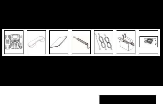
The Box Contents
Carefully remove the telephone from its shipping carton. If there are any visible indications of damage to the unit or accessories, do not attempt to operate it. Call International Resources at (888) 772-5200 for help.
Check the carton carefully for the following items. You should have:
L ii n e C a ll ll e rr II D T e ll e p h o n e
F o u r - L i n e C a l l e r I D T e l e p h o n e
IInsertt Productr t
Picturei
Here
NSQ412
MANUAL
NSQ412
OWNER’S MANUAL
Keep the box and all packing materials for storing or shipping the NSQ412. Keep all printed literature and proof of purchase for reference. On the base unit bottom, there is a serial number. Please write it below for future reference:
NSQ 412 SERIAL NUMBER: ______________________________________
NOTE: The Time/Date and Station Number should be programmed before using each station.
NSQ412 Four-Line Caller ID Telephone Owner’s Manual 5

Key and Indicator Descriptions
The following drawings provide identification and brief descriptions of the base controls, keys and indicators.
Cradle |
LCD Display |
|
|
|
|
Navigation keys |
|
|
|
|
|
|
|
|
|
|
|
|
|
|
|
|
Caller key |
|||||||||||||||||||||||||||||||||||||||||||||||||||||||||||||||||||||||||||||||||||||||||||||||||||||||||||||||||||||||||||||||
Hook Switch |
|
|
|
|
|
|
|
|
|
|
|
|
|
|
|
|
|
|
|
|
|
|
|
|
|
|
|
|
|
|
|
|
|
|
|
|
|
|
|
|
|
|
|
|
|
|
|
|
|
|
|
|
|
|
|
|
|
|
|
|
|
|
|
|
|
|
|
|
|
|
|
|
|
|
|
|
|
|
|
Ring LED |
||||||||||||||||||||||||||||||||||||||||||||||||||||||||||||||||||||||
Speed Dial Keys |
|
|
|
|
|
|
|
|
|
|
|
|
|
|
|
|
|
|
|
|
|
|
|
|
|
|
|
|
|
|
|
|
|
|
|
|
|
|
|
|
|
|
|
|
|
|
|
|
|
|
|
|
|
|
|
|
|
|
|
|
|
|
|
|
|
|
|
|
|
|
|
|
|
|
|
|
|
|
|
|
||||||||||||||||||||||||||||||||||||||||||||||||||||||||||||||||||||||
Handset Guide |
|
|
|
|
|
|
|
|
|
|
|
|
|
|
|
|
|
|
|
|
|
|
|
|
|
|
|
|
|
|
|
|
|
|
|
|
|
|
|
|
|
|
|
|
|
|
|
|
|
|
|
|
|
|
|
|
|
|
|
|
|
|
|
|
|
|
|
|
|
|
|
|
|
|
|
|
|
|
|
MSGWait/NewCID LED |
||||||||||||||||||||||||||||||||||||||||||||||||||||||||||||||||||||||
|
|
|
|
|
|
|
|
|
|
|
|
|
|
|
|
|
|
|
|
|
|
|
|
|
|
|
|
|
|
|
|
|
|
|
|
|
|
|
|
|
|
|
|
|
|
|
|
|
|
|
|
|
|
|
|
|
|
|
|
|
|
|
|
|
|
|
|
|
|
|
|
|
|
|
|
|
|
|
||||||||||||||||||||||||||||||||||||||||||||||||||||||||||||||||||||||||
Speed Dial index |
|
|
|
|
|
|
|
|
|
|
|
|
|
|
|
|
|
|
|
|
|
|
|
|
|
|
|
|
|
|
|
|
|
|
|
|
|
|
|
|
|
|
|
|
|
|
|
|
|
|
|
|
|
|
|
|
|
|
|
|
|
|
|
|
|
|
|
|
|
|
|
|
|
|
|
|
|
|
|
CID List key |
||||||||||||||||||||||||||||||||||||||||||||||||||||||||||||||||||||||
Speaker Grille |
|
|
|
|
|
|
|
|
|
|
|
|
|
|
|
|
|
|
|
|
|
|
|
|
|
|
|
|
|
|
|
|
|
|
|
|
|
|
|
|
|
|
|
|
|
|
|
|
|
|
|
|
|
|
|
|
|
|
|
|
|
|
|
|
|
|
|
|
|
|
|
|
|
|
|
|
|
|
|
Volume and keys |
||||||||||||||||||||||||||||||||||||||||||||||||||||||||||||||||||||||
|
|
|
|
|
|
|
|
|
|
|
|
|
|
|
|
|
|
|
|
|
|
|
|
|
|
|
|
|
|
|
|
|
|
|
|
|
|
|
|
|
|
|
|
|
|
|
|
|
|
|
|
|
|
|
|
|
|
|
|
|
|
|
|
|
|
|
|
|
|
|
|
|
|
|
|
|
|
|
||||||||||||||||||||||||||||||||||||||||||||||||||||||||||||||||||||||||
Pause key |
|
|
|
|
|
|
|
|
|
|
|
|
|
|
|
|
|
|
|
|
|
|
|
|
|
|
|
|
|
|
|
|
|
|
|
|
|
|
|
|
|
|
|
|
|
|
|
|
|
|
|
|
|
|
|
|
|
|
|
|
|
|
|
|
|
|
|
|
|
|
|
|
|
|
|
|
|
|
|
|
|
|
|
|
|
|
|
|
|
|
|
|
Directory key |
|||||||||||||||||||||||||||||||||||||||||||||||||||||||||
|
|
|
|
|
|
|
|
|
|
|
|
|
|
|
|
|
|
|
|
|
|
|
|
|
|
|
|
|
|
|
|
|
|
|
|
|
|
|
|
|
|
|
|
|
|
|
|
|
|
|
|
|
|
|
|
|
|
|
|
|
|
|
|
|
|
|
|
|
|
|
|
|
|
|
|
|
|
|
|
|
|
|
|
|
|
|
|
|
|
|
|
|
|
|||||||||||||||||||||||||||||||||||||||||||||||||||||||||
|
|
|
|
|
|
|
|
|
|
|
|
|
|
|
|
|
|
|
|
|
|
|
|
|
|
|
|
|
|
|
|
|
|
|
|
|
|
|
|
|
|
|
|
|
|
|
|
|
|
|
|
|
|
|
|
|
|
|
|
|
|
|
|
|
|
|
|
|
|
|
|
|
|
|
|
|
|
|
|
|
|
|
|
|
|
|
|
|
|
|||||||||||||||||||||||||||||||||||||||||||||||||||||||||||||
|
|
|
|
|
|
|
|
|
|
|
|
|
|
|
|
|
|
|
|
|
|
|
|
|
|
|
|
|
|
|
|
|
|
|
|
|
|
|
|
|
|
|
|
|
|
|
|
|
|
|
|
|
|
|
|
|
|
|
|
|
|
|
|
|
|
|
|
|
|
|
|
|
|
|
|
|
|
|
|
|
|
|
||||||||||||||||||||||||||||||||||||||||||||||||||||||||||||||||||||
Headset jack (on side) |
|
|
|
|
|
|
|
|
|
|
|
|
|
|
|
|
|
|
|
|
|
|
|
|
|
|
|
|
|
|
|
|
|
|
|
|
|
|
|
|
|
|
|
|
|
|
|
|
|
|
|
|
|
|
|
|
|
|
|
|
|
|
|
|
|
|
|
|
|
|
|
|
|
|
|
|
|
|
|
|
|
Conf key |
||||||||||||||||||||||||||||||||||||||||||||||||||||||||||||||||||||
Handset jack (on side) |
|
|
|
|
|
|
|
|
|
|
|
|
|
|
|
|
|
|
|
|
|
|
|
|
|
|
|
|
|
|
|
|
|
|
|
|
|
|
|
|
|
|
|
|
|
|
|
|
|
|
|
|
|
|
|
|
|
|
|
|
|
|
|
|
|
|
|
|
|
|
|
|
|
|
|
|
|
|
|
|
|
|
|
|
Flash key |
|||||||||||||||||||||||||||||||||||||||||||||||||||||||||||||||||
Page key |
|
|
|
|
|
|
|
|
|
|
|
|
|
|
|
|
|
|
|
|
|
|
|
|
|
|
|
|
|
|
|
|
|
|
|
|
|
|
|
|
|
|
|
|
|
|
|
|
|
|
|
|
|
|
|
|
|
|
|
|
|
|
|
|
|
|
|
|
|
|
|
|
|
|
|
|
|
|
|
|
|
|
|
|
|
|
|
|
|
|
|
|
|
|
|
|
|
|
|
|
|
|
|
|
|
|
|
Release key |
||||||||||||||||||||||||||||||||||||||||||
(Auto)Redial key |
|
|
|
|
|
|
|
|
|
|
|
|
|
|
|
|
|
|
|
|
|
|
|
|
|
|
|
|
|
|
|
|
|
|
|
|
|
|
|
|
|
|
|
|
|
|
|
|
|
|
|
|
|
|
|
|
|
|
|
|
|
|
|
|
|
|
|
|
|
|
|
|
|
|
|
|
|
|
|
|
|
|
|
|
|
|
|
|
|
|
|
|
|
|
|
|
|
|
|
|
|
|
|
|
|
|
|
|
Remove key |
|||||||||||||||||||||||||||||||||||||||||
Intercom key |
|
|
|
|
|
|
|
|
|
|
|
|
|
|
|
|
|
|
|
|
|
|
|
|
|
|
|
|
|
|
|
|
|
|
|
|
|
|
|
|
|
|
|
|
|
|
|
|
|
|
|
|
|
|
|
|
|
|
|
|
|
|
|
|
|
|
|
|
|
|
|
|
|
|
|
|
|
|
|
|
|
|
|
|
|
|
|
|
|
|
|
|
|
|
|
|
|
|
|
|
|
|
|
|
|
|
|
|
|
|
|
|
|
|
|
|
|
|
|
|
|
|
|
|
|
Save key |
||||||||||||||||||||||||
DND key |
|
|
|
|
|
|
|
|
|
|
|
|
|
|
|
|
|
|
|
|
|
|
|
|
|
|
|
|
|
|
|
|
|
|
|
|
|
|
|
|
|
|
|
|
|
|
|
|
|
|
|
|
|
|
|
|
|
|
|
|
|
|
|
|
|
|
|
|
|
|
|
|
|
|
|
|
|
|
|
|
|
|
|
|
|
|
|
|
|
|
|
|
|
|
|
|
|
|
|
|
|
|
|
|
|
|
|
|
|
|
|
|
|
|
|
|
|
|
|
|
|
|
|
|
|
|
|
|
|
|
|
|
|
|
Program key |
|||||||||||||||
Mute key |
|
|
|
|
|
|
|
|
|
|
|
|
|
|
|
|
|
|
|
|
|
|
|
|
|
|
|
|
|
|
|
|
|
|
|
|
|
|
|
|
|
|
|
|
|
|
|
|
|
|
|
|
|
|
|
|
|
|
|
|
|
|
|
|
|
|
|
|
|
|
|
|
|
|
|
|
|
|
|
|
|
|
|
|
|
|
|
|
|
|
|
|
|
|
|
|
|
|
|
|
|
|
|
|
|
|
|
|
|
|
|
|
|
|
|
|
|
|
|
|
|
|
|
|
|
|
|
|
|
|
|
|
|
|
|
|
|
|
|
|
|
|
|
|
|
|
|
|
|
Line keys |
Dial keys |
|
|
|
|
|
|
|
|
|
|
|
|
|
|
|
|
|
|
|
|
|
|
|
|
|
|
|
|
|
|
|
|
|
|
|
|
|
|
|
|
|
|
|
|
|
|
|
|
|
|
|
|
|
|
|
|
|
|
|
|
|
|
|
|
|
|
|
|
|
|
|
|
|
|
|
|
|
|
|
|
|
|
|
|
|
|
|
|
|
|
|
|
|
|
|
|
|
|
|
|
|
|
|
|
|
|
|
|
|
|
|
|
|
|
|
|
|
|
|
|
|
|
|
|
|
|
|
|
|
|
|
|
|
|
|
|
|
|
|
|
|
|
|
|
|
|
Jog knob/Dial key |
|||
Speaker key |
Hold/Transfer key |
|
|
|
|
Headset key |
|
|
|
|
|
|
|
|
|
|
|
|
|
|
|
|
Microphone (on bottom-side) |
|||||||||||||||||||||||||||||||||||||||||||||||||||||||||||||||||||||||||||||||||||||||||||||||||||||||||||||||||||||||||||||||
|
|
|
|
|
|
|
|
|
|
|
|
|
|
|
|
|
|
|
|
|
|
|
|
|
|
|
|
|
|
|
|
|
|
|
|
|
|
|
|
|
|
|
|
|
|
|
|
|
|
|
|
|
|
|
|
|
|
|
|
|
|
|
|
|
|
|
|
|
|
|
|
|
|
|
|
|
|
|
|
|
|
|
|
|
|
|
|
|
|
|
|
|
|
|
|
|
|
|
|
|
|
|
|
|
|
|
|
|
|
|
|
|
|
|
|
|
|
|
|
|
|
|
|
|
|
|
|
|
|
|
|
|
|
|
|
|
|
|
|
|
|
|
|
|
|
|
|
|
|
|
NSQ412 Four-Line Caller ID Telephone Owner’s Manual 6

Cradle: The place to put the handset when not in use.
Hook Switch: The switch that connects a call when released and disconnects a call when depressed.
Handset Guide: This sits flush for desk use and provides a hook to hold the handset when wall mounted.
Speaker Grille: The location of the Speakerphone speaker.
[SPD#] keys: Eight keys used for storing often-used telephone numbers, Voicemail Navigation codes, and Network Feature codes.
Speed Dial Index: Removable index for identifying the contents of the Speed Dial keys.
[PAUSE] key: Used for inserting a 3-sec- ond pause between digits when dialing.
[PAGE] key: Initiates and answers page.
Headset Jack (on side): Used for con-
necting an optional external headset.
Handset Jack (on side): Used to connect the coiled handset cord.
[(AUTO)REDIAL] key: Redials the last number or starts the Auto-Redial process. The integrated LED will indicate the Auto-Redial status.
[INTERCOM] key: Initiates and answers the Intercom. The integrated LED will indicate the status.
[DND] key: Activates and disables the Do Not Disturb operation. The integrated LED will indicate the status.
[MUTE] key: Activates and disables the microphone for a private conversation in your room without affecting the incoming audio. The integrated LED will indicate the status.
[DIAL] keys: The 12-keys for dialing and programming telephone numbers. NOTE: the [*/TONE] key temporarily changes the dial operation to Tone if the dialing is set to Pulse.
[SPEAKER] key: Activates and disables the Speakerphone operation. The integrated LED will indicate the status.
LCD Display: The Liquid Crystal Display shows the operational status of the station.
[HOLD/TRANSFER] key: Activates and disables the Hold and Transfer features. The integrated LED will indicate the status.
Navigation [<] and [>] keys: Used to move the cursor when entering data. Also enters and exits levels when programming.
[HEADSET] key: Activates and disables the optional headset. The integrated LED will indicate the headset status.
[CALLER] key: Used to show other screens when more than one line is ringing.
Ring LED: Flashes when the station is ringing.
NSQ412 Four-Line Caller ID Telephone Owner’s Manual 7
MSG Wait/New CID LED: Will indicate when a voicemail message has been left in your telephone company voicemail box and when new Caller ID records have been received.
[CID LIST] key: Used to access the Caller ID records.
[DIRECTORY] key: Used to access the Private and Public Directories.
[CONF] key: Used to conference two
calls |
the station. |
|
Volume |
and |
keys: Use to adjust |
the Handset, Speakerphone, Headset and Ringer volume.
[FLASH] key: Provides a momentary break in the telephone line for accessing special features like Call Waiting.
[RELEASE] key: Used to quit the current function or display.
[REMOVE] key: Used to delete the programming or Caller ID in the display.
[SAVE] key: Used to store the displayed
programming.
[PROGRAM] key: Used to start the programming operation.
[LINE 1], [LINE 2], [LINE 3] and [LINE 4] keys: Used to manually select a line.
The integrated LEDs will indicate each line status.
[JOG] knob and [DIAL] key: Rotating the [JOG] knob changes the displayed items. Pressing the [DIAL] button will dial the telephone number shown in the display.
Microphone (on bottom-side): Used for
the speakerphone outgoing audio.
Power |
Data Jack 1 |
Data Jack |
2 |
jack |
Line 3 |
Line 4 |
|
Telephone Jack |
Telephone Jack |
Line 1/2 |
Line 3/4 |
Line Jacks: Jack L1/L2 is used for telephone lines 1 and 2. Jack L3/L4 is used for telephone lines 3 and 4. Data jacks 1 and 2 are used to connect a fax, modem or other device through the NSQ412 to the telephone line.
Power Jack: The jack for connecting the a. c. power adapter to the station.
NSQ412 Four-Line Caller ID Telephone Owner’s Manual 8

A. C. Adapter Hook |
Telephone Line Cord Channel |
Product label
Caution label
Serial Number


 label Battery

 Compartment
Wall mounting holes
Low profile stand mounting holes
High profile stand mounting holes
A. C. Adapter Hook: Secures the A. C. Adapter wire, preventing accidental removal.
Battery Compartment: Location for the 9-V battery that allows limited opertion during a power failure.
Telephone Line Cord Channel:
A groove for routing the telephone line cord during wall mounting.
Caution label: Important warning information.
Product Label: Identifies the unit and provides information.
Serial Number Label: Identifies when the product was manufactured.
Wall Mounting Holes: Standard holes designed to fit Western Electric and Verizon AE style wall jacks.
Low Profile Stand Mounting holes: Used with the stand for a low profile
desk installation.
High Profile Stand Mounting Holes: Used with the stand for a high profile
desk installation.
NSQ412 Four-Line Caller ID Telephone Owner’s Manual 9

Installation Preparation
Installing the NSQ412 is easy as long as you do a little planning before starting. Locate each station within ten feet of an a. c. power outlet and seven feet of the telephone jacks. The maximum amount of telephone wire that can be between two stations is 600 feet.
IMPORTANT: Taking full advantage of the system features requires that the telephone number connected to Line 1 be the same on all stations. If this is not done, the Privacy, Intercom, Page and Transfer will not work properly. In addition, it is strongly recommended that no other devices operate on Line 1 besides the NSQ412 stations. Any interference on it can degrade the system performance. The system can be used on a DLS line if either: 1) Line 1 is not the DSL line; or 2) Line 1 wiring connected to all stations is behind the DSL filter port.
There are many different wiring configurations that a telephone jack can have. The station will support both a home run (the phone line is run from a connecting block to each station) and daisy chain (the phone line is run from one phone to the next) wiring configuration. Many older homes and businesses have just one telephone line on each jack. Newer homes and businesses typically have two or three lines per jack. You must identify how your telephone jacks are wired before connecting them to the NSQ412. If you cannot determine this, call your telephone service provider for assistance.
It is a good idea to document the phone wiring for each NSQ412 location. This can be done using the following work sheet. Record the telephone number for each line and the jack it is found on for each station.
NSQ412 Four-Line Caller ID Telephone Owner’s Manual 10

Station Number Line 1/Jack Line 2/Jack Line 3/Jack Line 4/Jack 11 12 13 14 15 16 17 18 19 20 21 22
For example, stations 11, 12 and 13 will have telephone numbers 555-1111 on Line 1, and 555-2222 on Line 2. Station 11 and 12 will have 555-3333 on Line 3. Station 11 will have 555-4444 on line 4. Stations 12 and 13 will have 555-5555 on line 4. Station 13 will have 555-4444 on line 3. At station 11’s location, each telephone number has a separate jack. At station 12’s location, lines 1 and 2 share one jack and lines 3 and 4 share another jack. At station 13’s location, lines 1 and 2 share one jack while line 3 and line 4 each have separate jacks. The work sheet would be filled out as follows:
Station Number |
Line 1/Jack |
Line 2/Jack |
Line 3/Jack |
Line 4/Jack |
11 |
555-1111/jack 1 |
555-2222/jack 2 |
555-3333/jack 3 |
555-4444/jack 4 |
12 |
555-1111/jack 1 |
555-2222/jack 1 |
555-3333/jack 2 |
555-5555/jack 2 |
13 |
555-1111/jack 1 |
555-2222/jack 1 |
555-4444/jack 2 |
555-5555/jack 3 |
Each station has four telephone line jacks located on the base cabinet’s side. The first jack is for telephone lines 1 and 2. The second jack is for telephone lines 3 and 4. Jack 3 and jack 4 are Data jacks used for connecting a modem or fax machine to the
telephone network through the NSQ412.
NSQ412 Four-Line Caller ID Telephone Owner’s Manual 11

CAUTION!
1.Never install telephone jacks during a lightning storm.
2.Never install telephone jacks in wet locations unless the jack is specificaly designed for wet locations.
3.Never touch uninsulated telephone wires or terminals unless the telphone line has been disconnected at the network interface.
4.Use caution when installing or modifing telephone lines.
5.Always disconnect all telephone lines from the wall outlet before servicing or disassembling this equipment.
6.Danger of explosion if battery is incorectly replaced.
Installing the Telephone on a Desk or Table
Once the telephone jack-wiring configuration is determined, proceed with
installing the telephone. NOTE: Do not |
|
|
|
||
|
Low Profile |
High Profile |
|
||
connect the a. c. power adapter until |
|
|
|
|
|
|
|
|
|
||
instructed to do so. |
|
|
|
|
|
The following instructions show how to |
|
|
|
|
|
connect four telephone lines to the |
|
|
|
|
|
NSQ412. As few as one line can |
4. |
Attach the stand to either the low pro- |
|||
connected. |
|
file or high profile mounting holes. It |
|||
|
|
will snap into place. |
|
|
|
1. Carefully remove all of the telephone |
5. If telephone lines 1 and 2 are on one |
||||
components from their packing. |
|||||
|
jack and telephone lines 3 and 4 are |
||||
|
|
||||
2. Turn the unit over and remove the |
|
on another jack, see the following |
|||
|
connection drawing. Otherwise, go to |
||||
screw from the battery compartment |
|
||||
|
step 6. |
|
|
||
using a #2 Philips screwdriver. Open |
|
|
|
||
|
|
|
|
||
the battery door by pressing the tab. |
|
Connect telephone jack 1 to the |
|||
Install a 9V alkaline transistor radio |
|
||||
|
NSQ412 L1/L2 jack using one of the |
||||
battery. Be sure to install the battery |
|
||||
|
4-conductor telephone line cords su- |
||||
polarity correctly by observing the |
|
||||
|
plied with the telephone. Connect |
||||
drawing on the inside of the compart- |
|||||
telephone jack 2 to the NSQ412 |
|||||
ment. Replace the battery door and |
|
||||
|
L3/L4 jack using the other 4-condu- |
||||
the screw. |
|
||||
|
tor telephone line cord supplied with |
||||
|
|
||||
Lines 3/4 Lines 1/2 |
A.C. Power |
the telephone. |
|
|
|
3. Insert one end of the coiled handset cord into the handset’s jack and the other end into the base handset jack.
NSQ412 Four-Line Caller ID Telephone Owner’s Manual 12

6.If telephone lines 1, 2, 3, and 4 are all on separate jacks, two adapters and extra telephone line cords are necessary (not included with the telephone). See the following connection drawing.
Line 1 |
Line 2 |
2 LINE ADAPTER
Line 3 |
Line 4 |
2 LINE ADAPTER
The adapters will convert two separate telephone jacks into a single one. Connect telephone line 1 into the adapter. Connect telephone line 2 into the adapter. Connect the adapter output jack into the NSQ412 L1/L2 jack using one of the 4-conductor telephone line cords supplied with the telephone. Repeat this process using the second adapter for telephone
lines 3 and 4. Connect the output of the second adapter jack to the NSQ412 L3/L4 jack using the other telephone line cord supplied with the telephone.
If your telephone wiring does not match either of the examples above or one of their variations, you may need to call your telephone service provider for assistance. They can install the necessary jacks wired in the correct configuration.
7. Once the telephone line(s) are connected to the station, plug the a. c. adapter into the NSQ412 power jack. Route
the cord through the A. C. Adapter Hook, then connect the adapter to an electrical outlet. The station will initialize for about 7 seconds, then be ready for use.
The telephone has the programming set to the most common selections. See the
Quick Reference Card to begin using it immediately. Refer to the
Programming section of this manual for customizing the station’s operation and the Feature Sections for advanced operation and use.
Installing the Telephone on a
Wall
The station may be installed onto the studs of a telephone wall jack or onto 2 screws that are securely fastened to the wall. Once the telephone wall jack-wiring configuration is determined, proceed with the installation. NOTE: Do not connect the a. c. adapter until instructed to do so.
The following instructions show how to connect four telephone lines to the NSQ412. As few as one line can be connected.
1.Carefully remove all of the telephone components from their packing
2.Turn the unit over and remove the screw from the battery compartment using a #2 Philips screwdriver. Open the battery door by pressing the tab.
NSQ412 Four-Line Caller ID Telephone Owner’s Manual 13

Install a 9V alkaline transistor radio battery. Be sure to install the battery polarity correctly by observing the drawing on the inside of the compartment. Replace the battery door and the screw.
3.Plug one end of the coiled handset cord into the handset’s jack and the other end into the base handset jack.
4.For wall mounting, the handset must be retained securely in the cradle. The handset guide must be changed from the desk position to the wall position. To do this, pull the handset guide out and rotate it 180. It will now protrude slightly, providing a tab for the handset to rest on.
5.Connect the a. c. power adapter to the power jack on the NSQ412. Do not connect the adapter to the electrical outlet at this time. Route the adapter cord through the A. C. Adapter Hook on the station’s back.
If you are installing the NSQ412 to screws, skip down to step 12.
6.If you install the NSQ412 to the mounting studs of a telephone wall jack, lines 1 and 2 must be terminated to it. Lines 3 and 4 (if used) must be terminated to a different jack.
7.Connect the short 4-conductor telephone line cord supplied with the unit to the L1/L2 jack. Route the cord through the telephone line cord channel on the station’s back.
Lines 3/4 A.C. Adapter
8. Hold the station close to the telephone wall jack and plug the short line cord into it. Align the wall jack studs with the wall mounting holes on the NSQ412’s back.
9.Push the NSQ412 onto the studs and firmly pull downward (toward the floor), locking the station onto the wall jack.
10.Connect the other telephone jack with lines 3 and 4 to the NSQ412 jack L3/L4 using one long 4-conduc- tor telephone line cord supplied with the telephone.
11.Connect the a. c. adapter to an electrical outlet. The station will initialize for about 7 seconds, then be ready for use and programming.
61/2
NSQ412 Four-Line Caller ID Telephone Owner’s Manual 14

12.Follow these steps if the station will be installed on screws securely fastened to the wall. If telephone lines 1 and 2 are on one jack and tele phone lines 3 and 4 on another jack see the following connection draw-
ing. Otherwise go to step 13.
Lines 3/4 |
|
Lines 1/2 |
A.C. Power |
Connect telephone jack 1 to the NSQ412 L1/L2 jack using one of the 4-conductor telephone line cords supplied with the telephone. Connect telephone jack 2 to the NSQ412 L3/L4 jack using the other 4-conductor tlephone line cord sup plied with the telephone.
13.If telephone lines 1, 2, 3 and 4 are all on separate jacks, two adapters and extra telephone line cords are necessary (not included with the telephone). See the following connection drawing.
The adapters will convert two separate telephone jacks into a single one. Connect telephone line 1 into the adapter. Connect telephone line 2 into the adapter. Connect the adapter output jack into the NSQ412 L1/L2 jack using one of the 4-con-
ductor telephone line cords supplied with the telephone. Repeat this process using the second adapter for tele phone lines 3 and 4. Connect the output of the second adapter jack
to the NSQ412 L3/L4 jack using the other telephone line cord supplied with the telephone.
Line 1 |
Line 2 |
2 LINE ADAPTER
Line 3 |
Line 4 |
2 LINE ADAPTER
14.Using the supplied screw template, install the screws into the wall. Be sure to use anchors to ensure a secure mounting. Leave the screws protruding from the wall 3/16”.
15.Hold the station close to the screws and align them with the wall mounting holes on the NSQ412’s back.
Push the station onto the screws and firmly pull downward (towards the floor), locking the station to the wall.
16.Connect the a. c. adapter to an electrical outlet. The station will initialize for about 7 seconds, then be ready for use.
The telephone has the programming set to the most common selections. See the Quick
Reference Card to begin using it immediately. Refer to the Programming section of this manual for customizing the station’s operation and the Feature Sections for advanced operation and use.
NSQ412 Four-Line Caller ID Telephone Owner’s Manual 15
 Loading...