

Page 1
M7100
Wireless Handheld Terminal
User’s Guide
© 2007 American Microsystems LTD.
Effective Date: May 2007
AML Website: www.amltd.com
Page 2

M7100 HANDHELD TERMINAL
User’s Guide
Disclaimer
American Microsystems, Ltd. reserves the right to make changes in specifications and other information contained in this
document without prior notice, and the reader should in all cases consult American Microsystems, Ltd. to determine
whether any such changes have been made. The information in this publication does not represent a commitment on the
part of American Microsystems, Ltd.
American Microsystems, Ltd. shall not be liable for technical or editorial errors or omissions contained herein; nor for
incidental or consequential damages resulting from the furnishing, performance, or use of this material.
This document contains proprietary information which is protected by copyright.
All rights are reserved. No part of this document may be photocopied, reproduced, or translated into another language
without the prior written consent of American Microsystems, Ltd.
FCC Declaration of Conformity
Product Name: Model 7100 Wireless Handheld Terminal
Model Number: M7100
Radio Frequency Interference Requirements
This equipment complies with Part 15 of the FCC Rules. Operation is subject to the following two conditions: (1) This
equipment may not cause harmful interference, and (2) this equipment must accept any interference received, including
interference that may cause undesired operation.
This equipment has been tested and found to comply with the limits for a Class A digital device, pursuant to Part 15 of the
FCC Rules. These limits are designed to provide reasonable protection against harmful interference when the equipment
is operated in a residential environment. This equipment generates uses and can radiate radio frequency energy, and if
not installed and used in accordance with the instructions, may cause harmful interference to radio communications.
However, there is no guarantee that interference will not occur in a particular installation. If you determine the equipment
does cause harmful interference to radio or television reception (this may be determined by monitoring the interference
while turning the equipment off and on), you are encouraged to try to correct the interference by one of the following
measures:
• Reorient or relocate the receiving antenna.
• Increase the separation between the equipment and receiver.
• Connect the equipment into an outlet on a circuit different from that to which the receiver is connected.
• Consult the dealer or an experienced radio or TV technician for help.
Changes or modifications not expressly approved by American Microsystems, Ltd. could void the user's authority to
operate the equipment.
Normalización y Certificación Electronica (NYCE)
Safety NOM / NYCE-NOM-019-SCFI-1998
Safety of data processing equipment.
© 2007 American Microsystems, Ltd. All rights reserved.
2190 Regal Parkway • Euless, TX 76040
Phone 817.571.9015 • Fax 817.571.6176
Web Address: www.amltd.com
Page 3

TABLE OF CONTENTS
INTRODUCING THE M7100 1
What to Expect 1
Warranty 2
General Conventions 2
M7100 TERMINAL OVERVIEW 3
Using the M7100 Keyboard 3
Key Values 4
The M7100 Display Screen 6
The M7100 Scanner 6
The M7100 Scanner LED 11
Scanner information and Labeling 12
The M7100 Internal Radio 14
802.11b Fallback Mode 14
Interference and Coexistence 14
Security Issues 14
Ad-Hoc Mode 15
GSM/GPRS Network Card Support 17
Installing the GPRS SIM Card 17
Installing the Optional M7100 Handle 21
The M7100 Communications Ports 22
The M7100 Cradle 23
THE M7100 RF SERVER LOGIN 25
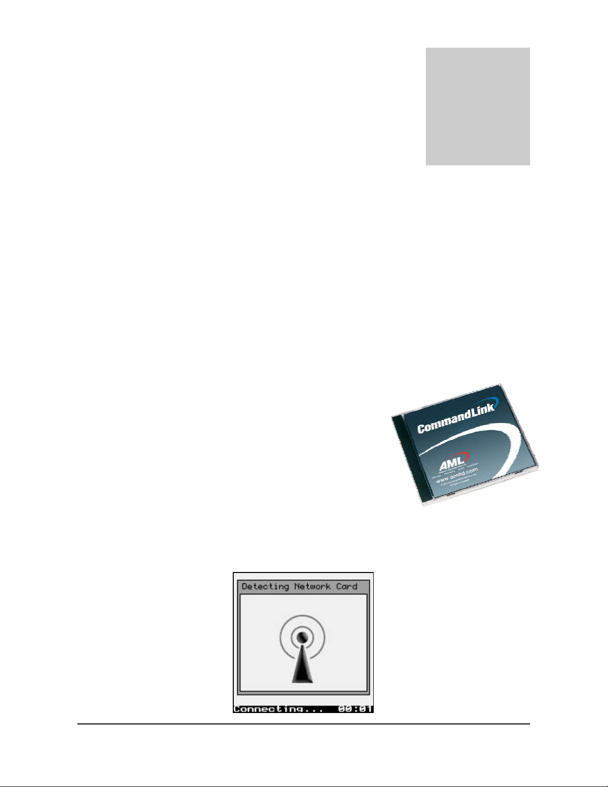
The CommandLink™ Software 25
Wait WLAN 25
Connecting 26
Login 26
Applications 27
Telnet 27
Switching Virtual Consoles 27
Terminal Emulation 28
Updating Firmware 29
THE M7100 MENU SYSTEM 30
Main Menu 30
Reconnect 30
Contrast 31
Network Setup 32
Radio Settings (WEP) 33
Radio Settings (WPA-PSK) 37
Radio Settings (WPA-EAP) 38
Simultaneous Hosts Connection 40
Multiple Hosts 41
Hosts Log-in Options 42
Terminal Options 43
Terminal Emulation - amlterm 43
Terminal Emulation – vt100 / vt220 44
Terminal Emulation – tn5250 53
Power Management 57
Diagnostics 59
Network Status 59
Resource Information 61
Resource Information 62
Ping Server 62
Print Test Label 64
Firmware Version 65
Serial Number 65
Battery Status 65
Barcode Data Viewer 66
Ping USB Server 67
Hardware Tests 67
Local Settings, Laser & CCD Only 68
Barcode Options 68
Symbology Settings 68
Setting the Code 39 Bar Code 69
Setting the UPC Bar Code 70
Setting the EAN Bar Code 71
UPC/EAN Supplements Settings 72
Setting the I - 2 of 5 Bar Code 74
Setting the Codabar Bar Code 75
Setting the Code 128 Bar Code 76
Setting the Code 93 Bar Code 77
Setting the MSI/Plessey Bar Code 77
Setting the Code 11 Bar Code 79
Setting the RSS Bar Code 79
Page 4

Decoder Options 81
Local Settings, 2D Imager Only 83
Barcode Options 83
Symbology Settings 83
Setting the Code 39 Bar Code 84
Setting the PDF417 Bar Code 85
Setting the MicroPDF417 Bar Code 86
Setting the RSS Bar Code 86
Setting the Composite Bar Code 87
Setting the UPC-A Bar Code 88
Setting the UPC-E Bar Code 89
Setting the EAN/JAN-13 Bar Code 90
Setting the EAN/JAN-8 Bar Code 91
Setting the 2 of 5(s) Bar Codes 92
Setting the Codabar Bar Code 93
Setting the Code 128 Bar Code 94
Setting the Code 93 Bar Code 95
Setting the MSI/Plessey Bar Codes 95
Setting the Code 11 Bar Code 96
Setting the Telepen Bar Code 97
Setting the PosiCode Bar Code 97
Setting the Codablock F Bar Code 98
Setting the Code 16K Bar Code 99
Setting the Code 49 Bar Code 99
Setting the Aztec Bar Code 100
Setting the QR Code Bar Code 100
Setting the Data Matrix Bar Code 101
Setting the MaxiCode Bar Code 101
Setting the Postal Bar Codes 102
Setting the Code 32 Bar Code 103
Setting the Trioptic Bar Code 104
Decoder Options 104
Laser / CCD Setting 106
Imager Options (2D Imager Only) 107
Bar Code Edit Options 108
Beep Options 110
Saving Bar Code Settings 110
Date/Time
Page 5

GETTING STARTED
Chapter
1
T
Introducing the M7100
This chapter describes how to get started using your M7100 handheld
terminal and get you up and running fast.
he M7100 handheld terminal is an ultra-versatile, high-performance, designed-to-fityour-budget terminal. The ergonomic design easily fits in even the smallest of
hands. It is rugged, lightweight, compact and easy-to-use. The high resolution
graphical display is capable of presenting a multitude of fonts and images.
The M7100 utilizes a true, fully functional, Linux operating system. The Linux operating
system is well known for its stability, speed and conservative memory usage. The Linux
operating system coupled with the M7100’s high speed processor makes the M7100 one
of the fastest handheld terminals on the market today. In test after test the Linux
operating system has out-performed DOS based and Windows based operating systems
when compared on similar hardware platforms.
The M7100 is easy to use and program. Our specifically designed CommandLink™ RF
(Radio Frequency) software makes it easy to create custom applications for any
requirement. Our terminal emulation software makes it easy to integrate the M7100 into
legacy applications as well. You can even utilize standard BASIC software on the M7100
handheld terminal.
Power saving features of the M7100 includes auto-off and power save modes, which
reduce power consumption until an operator provides input. These features conserve
battery power and lengthen the time between charges or battery replacement. The M7100
was designed to operate for a full 8 hour shift without requiring the battery to be recharged or replaced.
What to Expect
This user’s guide provides you with an overall physical description, keypad values,
technical specifications and performance capabilities of the M7100 handheld terminal. In
addition you will learn how to:
1
Page 6

GETTING STARTED
• Connect to your host computer
• Customize your M7100 Terminal
• Create and execute programs
• Collect and upload data
• Send and receive data
• Connect and use the M7100 serial interface
Warranty
A one-year warranty against material defects and workmanship from the date of shipment
is guaranteed by American Microsystems, Ltd. Products are sold on the basis of
specifications applicable at the time of manufacture. American Microsystems, Ltd. shall
have no obligation to modify or update products once sold. At our option, we will repair
or replace, at no charge, any unit that proves to be defective providing the appropriate
steps are taken to procure an RMA (Return Materials Authorization) number and
shipping instructions from American Microsystems, Ltd.
General Conventions
Before you begin to use the M7100 terminal, it’s important that you understand key
conventions and terms used in this manual.
Keys Description
SMALL CAPS Refers to a specific menu selection contained in the M7100 in
order to continue or complete a task.
[KEY] The square brackets indicate a specific key on the M7100 handheld
terminal’s key pad.
Bold Words you type – for example when you are instructed to type
A:\setup. Bold also refers to existing filenames.
Italic ¤Notes
Italic/Bold Warning! And section references.
Click/Select After selecting a procedure or menu, “Click” means to press and
release the left mouse button. “Select” means that after you select
the menu item or action, you should press ENTER.
2
Page 7
Chapter
2
T
M7100 Terminal Overview
This chapter describes the features of the M7100 terminal.
o save time in the future, print a copy of this document. Choose Print from the File menu, and
press Enter to receive all the pages of examples and instructions.
Using the M7100 Keyboard
The M7100 Terminal is equipped with fifty-five keys that are divided into white, grey, blue, red,
yellow and black keys. When pressed, each key emits an audible beep to indicate that the M7100
terminal has detected the key press.
The red power key turns the M7100 on/off. You must press and hold
this key down to power off the unit. This prevents accidentally
powering off the unit if this key is momentarily pressed.
Note: The Power Key Wake-up feature is only available on units with
Decoder version 2.0 or later. On earlier versions the power key will
immediately shut off the unit. The Decoder can only be programmed at
the factory.
The white/black “light bulb” key turns on/off the display backlight.
The backlight will automatically shut off after a predetermined time
has expired. This predetermined time can be programmed by the user.
The yellow [SCAN] button activates the M7100 scan engine. The
button is conveniently located for right or left hand use.
The seven blue keys consist of [Func], four arrow keys and two
[ENTER] keys (for right or left hand use). The [Func] key activates
3
Page 8

the blue Function menu or the blue special characters. Function keys (F1 – F20) can be
programmed by many host systems, to be “hot keys” and select specific program items without
navigating the entire program.
The black [Shift] key toggles between upper and lower case mode and selects special characters on
the numeric keypad.
There are ten white numeric keys and one white period key. These keys are larger than the less
used alpha keys to enable easy inputting of numbers with the right or left thumb.
Thirty-three grey keys represent letters, special functions, Space and Menu keys. The [Alt], [Ctl],
[Ins], [? ¦ ] (backspace) and [Esc] keys are also grey keys near the bottom of the keyboard.
Key Values
Yellow Key
SCAN
Blue Keys
Func
Enter
5 (Up arrow)
Activates the built in scan engine. The red LED above the power
key indicates when the scan engine is active.
Selects special functions determined by the host system. Hitting
Func then a number selects a special function.
Functions 1 - 9 are selected by hitting the <Func> then <1>
through <9> keys.
Functions 11 – 19 are selected by hitting the <Alt> then <1>
through <9> keys.
Function 10 is selected using the <Func> then <0> key and
Function 20 is selected by using the <Alt> then <0> key.
Depending on the FUNC LOCK setting, hitting a number key will
select a number or a special function. Shift then Func toggles
FUNC LOCK on and off.
Performs the Enter function.
Moves the display screen up one line at a time or moves the
display screen up one menu level.
3 (Left arrow)
In terminal emulation, the <Shift> then <5> will move the
screen up one whole page.
Moves the cursor left one character at a time and toggles between
menu selection options.
In terminal emulation, the <Func> then <3> is Back TAB.
In terminal emulation, the <Shift> then <3> will move the
screen up one whole page.
4
Page 9

6 (Down arrow)
4 (Right arrow)
Grey Keys
Alpha Letters A-Z and special characters when Func key is pressed
Ins Inserts data at the cursor position and moves all existing data to
? ¦ Deletes characters at the cursor position or if cursor follows a
Moves the display screen down one line at a time or moves the
display screen down one menu level.
In terminal emulation, the <Shift> then <6> will move the
screen up one whole page.
Moves the cursor right one character at a time and toggles
between menu selection options.
In terminal emulation, the <Func> then <4> is TAB
(Forward Tab function).
In terminal emulation, the <Shift> then <4> will move the
screen up one whole page.
prior to letter key.
the right
string of characters, it deletes the characters to the left of the
cursor
Esc Exits operation being performed
Space Enters the space character
Red Keys
power Powers unit off/on
Black Key
Shift Selects upper and lower case characters, depending on the CAPS
White Keys
Numeric 0, 1, 2, 3, 4, 5, 6, 7, 8, 9, . (period) and Backlight Lamp.
LOCK setting. Func then Shift toggles CAPS LOCK on and off.
Shift also selects the special characters on the numeric keypad.
To toggle Caps Lock mode on or off,
hit [Func] then [Shift].
If Function Lock mode is enabled, to toggle Function
Lock mode on or off, hit [Shift] then [Func].
5
Page 10

The M7100 Display Screen
The M7100 handheld terminal includes a 160 pixel by 160 pixel grayscale graphical Liquid
Crystal Display (LCD). Programs can be written which mix text and graphics together on the
display.
Warning: This display is NOT a touch screen display and the operator should not use sharp
objects on the plastic window protecting the LCD display.
The M7100 Scanner
The M7100 handheld terminal normally comes equipped with a scan engine that is capable of
scanning single dimensional bar codes. An optional Area Imager is available for 2 dimensional bar
codes. The M7100 can be ordered with one of the following scan engines installed:
Linear Imager
Uses LED light and a CCD detector to “image” the bar code. The linear imager has a much shorter
scanning distance and is slightly harder to aim. The linear imager is less expensive than the laser
scan engines.
Scan Rate: 26 Scans / Second
Scan Angle: 48º Nominal
Min. Print Contrast: Minimum 20% absolute dark/light reflectance measured at 645 nm
Standard Range Laser
The Standard laser engine uses a moving laser and a standard laser detector. The standard laser is
suitable for most applications. The laser is easy to aim and reads most barcodes very quickly.
Scan Rate: 35 (± 5) Scans / Second
Scan Angle: 42º ± 2º
Min. Print Contrast: Minimum 20% absolute dark/light reflectance measured at 650 nm
Long Range Laser (LR)
6
Page 11

The Long Range laser engine uses a moving laser light with a highly sensitive laser detector. The
long range laser is used when the barcodes are going to be a great distance from the operator. The
long range laser includes a laser point (dot) feature to make it easy for the operator to aim at the
barcode before it starts to read.
Scan Rate: 35 (± 5) Scans / Second
Scan Angle: 23º ± 2º
Min. Print Contrast: Minimum 40% absolute dark/light reflectance measured at 650 nm
High Density Laser (HD)
The High Density laser engine uses a moving laser light with a highly sensitive laser detector. The
High Density laser is used when the barcodes are going to be very small and difficult to read with
a standard laser.
Scan Rate: 35 (± 5) Scans / Second
Scan Angle: 37º ± 2º
Min. Print Contrast: Minimum 40% absolute dark/light reflectance measured at 670 nm
Advanced Long Range Laser (ALR)
The Advanced Long Range laser engine uses a moving laser light with a highly sensitive laser
detector. The advanced long range laser is able to read farther than the standard long range laser.
The advanced long range laser also includes a laser point (dot) feature.
Scan Rate: 35 (± 5) Scans / Second
Scan Angle: 13º ± 2º
Min. Print Contrast: Minimum 40% absolute dark/light reflectance measured at 650 nm
Area Imager (2D)
The Area Imager uses a camera type sensor to acquire images of the target. Unlike a linear
scanner, the imager is able to scan barcodes in any orientation. The HHP Imager is also capable of
reading most 2D barcodes and Postnet barcodes.
Symbologies:
2 Dimensional - PDF417, MicroPDF417, MaxiCode, Data Matrix, QR Code,
Aztec, Aztec Mesas, Code 49, EAN/UCC Composite
Linear - Code 39, Code 128, Codabar, UPC, EAN, I 2of5, RSS, Code
93, Codablock F
Postal - Postnet, Planet Code, British Post, Canadian Post, Japanese
Post, KIX (Netherlands) Post
OCR Fonts - OCR-A, OCR-B
7
Page 12
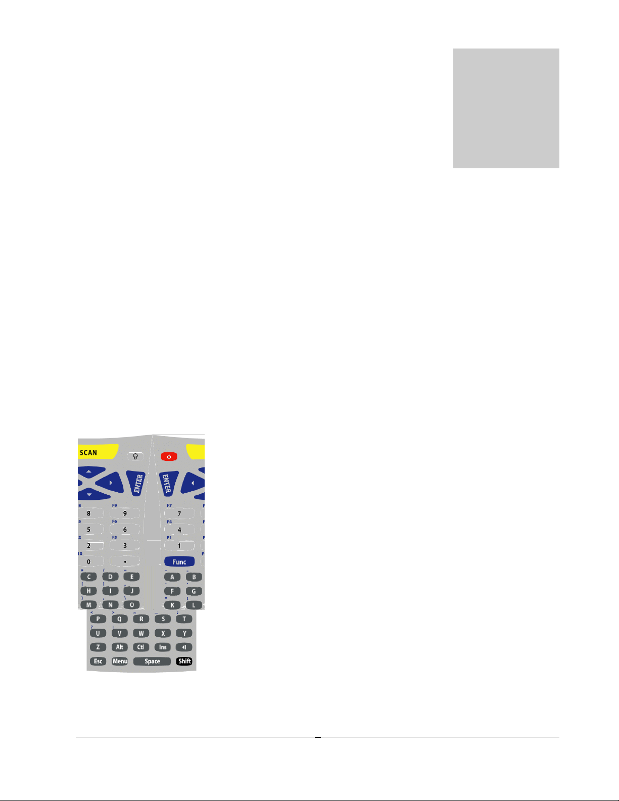
Reading distance for the Linear Imager and Code 39 Bar codes
Reading distance for the Linear Imager and all other bar code symbologies.
8
Page 13
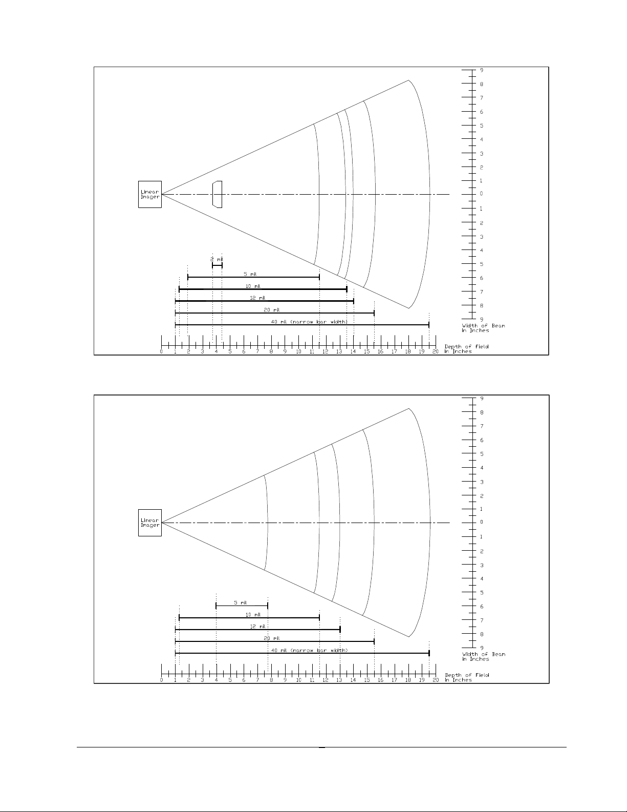
Reading distance for the Standard Range Laser
Reading distance for the High Density Laser
9
Page 14
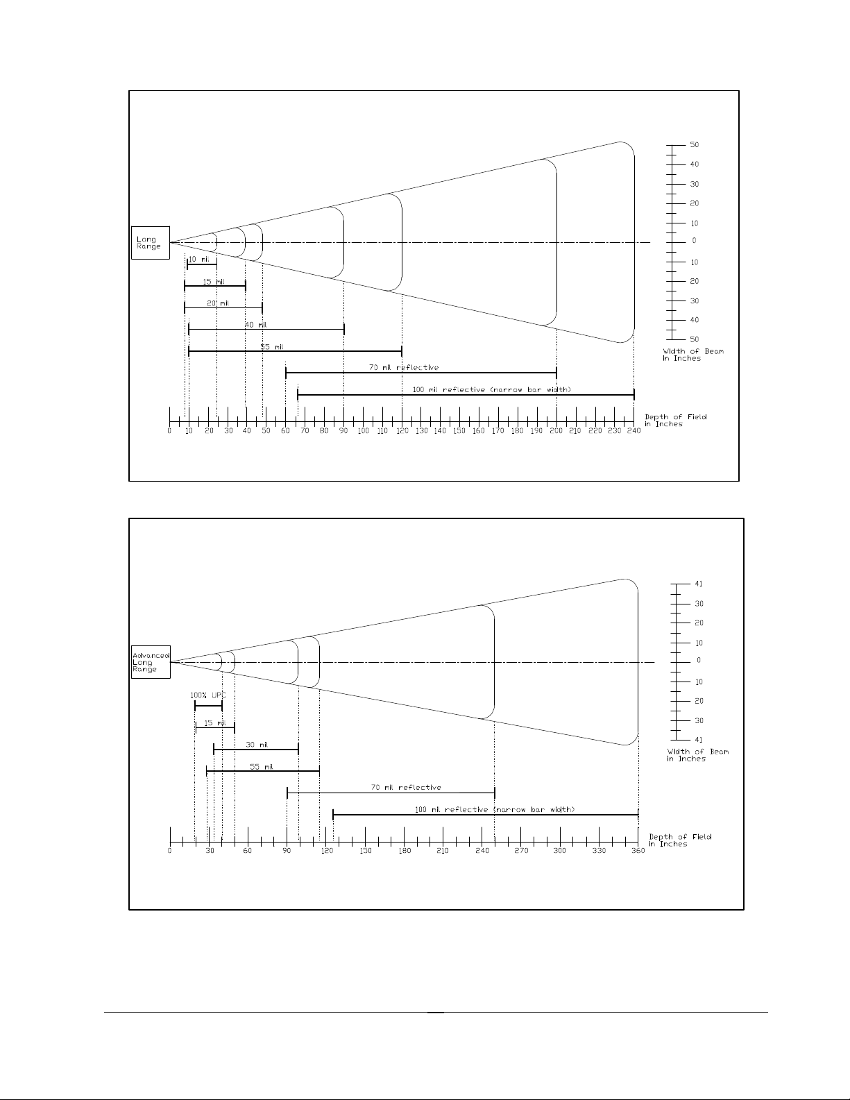
Reading distance for the Long Range Laser
Reading distance for the Advanced Long Range Laser
10
Page 15
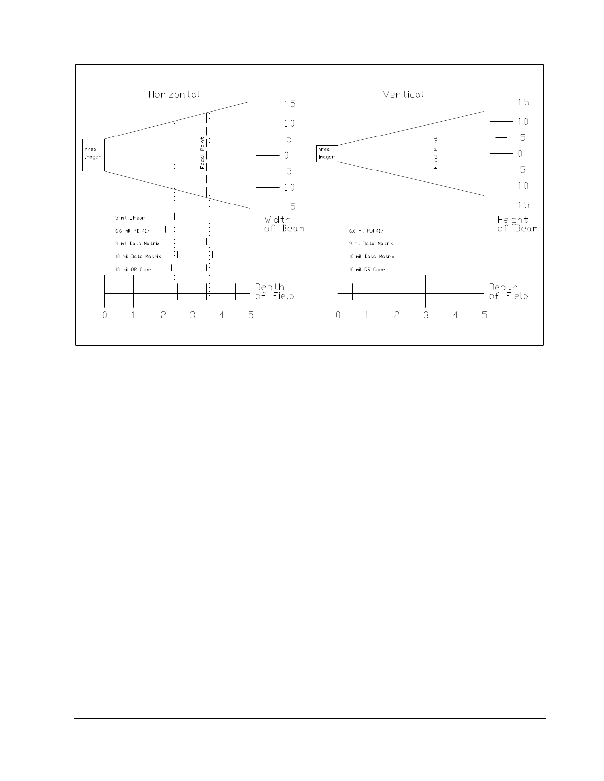
Reading distance for the 2D Area Imager
Barcode symbologies are always measured in mils. This usually refers to the narrowest bar
width. One mil equals 0.001”, therefore a 0.01” wide narrow bar would be a 10 mil barcode.
Conversion: 1 mil = 0.0254 mm
1 inch = 25.4 mm
These charts show typical performance at 68°F on high quality bar code symbols.
The M7100 Scanner LED
The M7100 has a multi-color LED to indicate when the unit has scanned a bar code successfully.
When the scan button is pushed, the LED above the on/off button will turn a solid red. Once the
scanner has successfully read the bar code, this LED will turn a bright green.
This visual indication of a good read is useful in very noisy environments where the audio beeper
can not be heard. If the red LED turns off, it means the bar code can not be read.
Note: On units built before February 2004, there was only a red LED when an item was scanned.
Note: When the M7100 is in sleep mode the scanner LED will be flashing red. You can press any
key to re-activate the unit.
11
Page 16
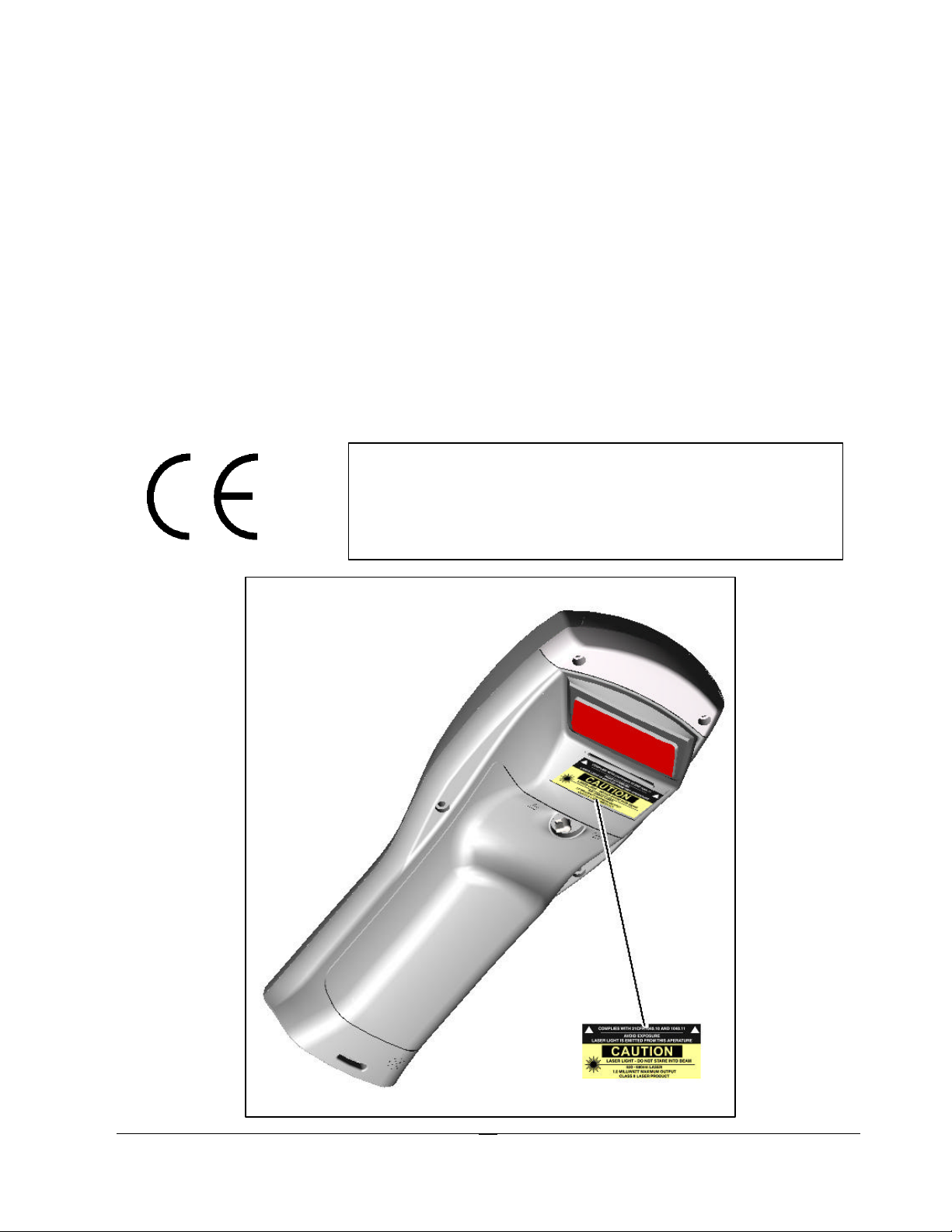
Scanner information and Labeling
The M7100 Integrated Laser Scanner uses a low-power visible laser diode. Avoid staring
directly into the light beam. Momentary exposure to a CDRH Class II laser is not known to
be harmful.
Laser Classification: CDRH Class II
Light Source: 630 – 680 nm laser diode
Laser Output Power: 1.0 milliwatt maximum output
FCC Information: This device complies with Part 15 of the FCC Rules. Operation is subject to the
following two conditions: (1) this device may not cause harmful interference, and
(2) this device must accept any interference received, including interference that
may cause undesired operation.
CAUTION: Use of controls, adjustment, or
performance of procedures other than those
specified herein may result in hazardous visible
laser light exposure.
12
Page 17

13
Page 18

The M7100 Internal Radio
The M7100 Handheld Terminal comes equipped with an internal 802.11b radio and antenna. This
internal radio is specifically designed to communicate with any 802.11b Access Point. The range
of the internal radio depends greatly on the quality of the Access Point and the RF
communications characteristic of the environment where the device is used. The typical range for
an 802.11b radio is 500 feet through free air. Additional Access Points must be added to improve
coverage in a larger area, or in electrically noisy RF environments.
802.11b Fallback Mode
Wireless LAN technology is designed to make maintaining a connection between two devices as
reliable and consistent as possible. Since the speed of the connection between wireless devices
will vary as range and signal quality varies, the wireless devices will intentionally sacrifice
throughput (data rate or connection speed as measured in bits per second) in exchange for
maintaining a reliable connection. In other words, a reliable connection at a lower speed is
preferred over an unreliable connection at a higher speed (i.e., it is easier to maintain the
connection if data rate is deliberately reduced, or put another way, lower data rates will tolerate a
higher range and/or worse signal quality). This characteristic is known as fallback. As example, an
802.11b system will fallback from 11 Mbps to 5.5 Mbps as range increases or signal quality
decreases. Subsequent fallbacks from 5.5 Mbps to 2 Mbps and 1 Mbps are also supported
Interference and Coexistence
802.11b operates in a range of radio frequencies known as an "unlicensed" band (i.e. the FCC does
NOT require the use of a license in order to operate a radio transmitter in this range). This means
that commercially available radio devices other than wireless LAN devices are permitted to use
the same frequency band as 802.11b. Consequently, these co-existing radio devices can interfere
or "jam" the wireless LAN (and vice versa). Ironically, the most troublesome devices are cordless
telephones and microwave ovens.
Fortunately, higher quality cordless phones tend to "listen" for a clear channel before becoming
active and will thus avoid interfering with a wireless LAN (i.e., the cordless phone seeks a clear
channel for itself so naturally avoids being interfered with or being a source of interference).
Jamming from microwave ovens is more severe but is usually restricted to the upper frequency
range for 802.11b (it should be noted that 802.11b divides the available frequency band into 11
channels. The higher numbered channels are most susceptible to microwave oven interference).
In each instance, jamming occurs only when the cordless telephone or microwave oven is active.
Security Issues
Much has been publicized in the media about security problems with wireless LANs. Although it
cannot be denied that the encryption algorithms currently used in 802.11b are flawed, the fact is
that security breaches of a wireless LAN require a deliberate attempt to access the network by an
intruder. It is highly recommended that WEP encryption be used and in some cases the access
14
Page 19
points should be set for MAC filtering. When an access point has MAC filtering enabled, the only
devices that can communicate through them are the ones which the MAC address has been set.
The primary issue is that many current users of wireless LAN have opted NOT to turn on security
features. If users were to enable the security features currently available (including only allowing
known systems access to the network and enabling WEP (Wired Equivalent Privacy) encryption
the intruder's work is much harder. Much as a burglar will bypass a house whose doors and
windows are securely locked, so too will a hacker tend to bypass a network where security
measures are enabled.
Ad-Hoc Mode
Most installed wireless LANs today utilize "infrastructure" mode that requires the use of one or
more access points. With this configuration, the access point provides an interface to a distribution
system (e.g., Ethernet), which enables wireless users to utilize the corporate network and the
CommandLink server.
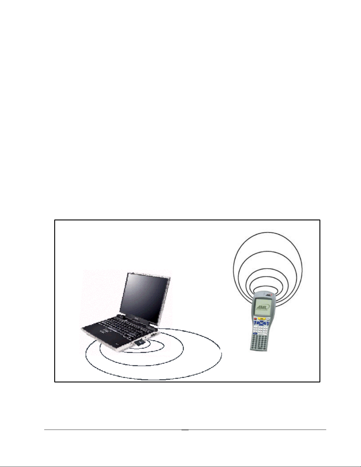
As an optional feature, however, the 802.11b standard specifies "ad-hoc" mode, which allows the
radio network interface card (NIC) to operate in what the standard refers to as an independent
basic service set (IBSS) network configuration. With an IBSS, there are no access points. User
devices communicate directly with each other in a peer-to-peer manner.
This illustration shows the M7100 handheld terminal using Ad-hoc mode.
The next illustration shows the M7100 handheld terminal in a typical wireless network.
15
Page 20
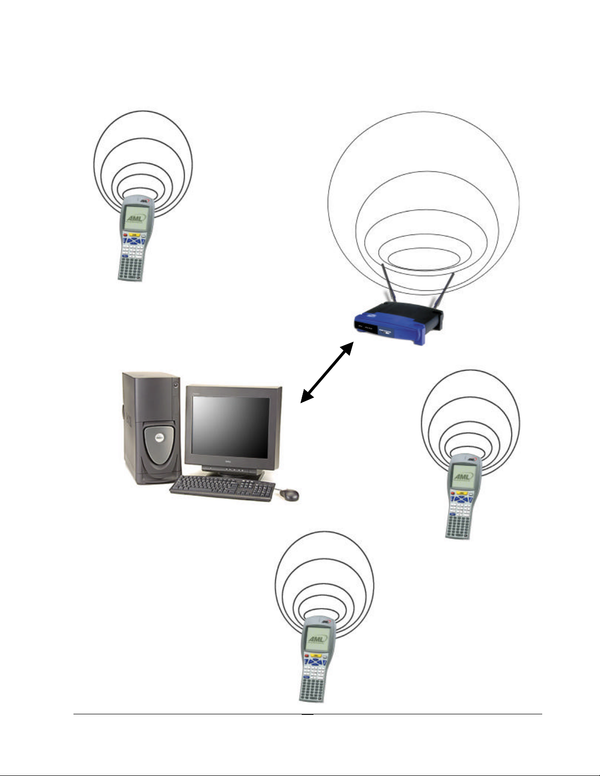
Personal
Computer
(Server)
A Typical Wireless Network
Wireless Access
Point(s)
(802.11b)
Ethernet
Connectio
Wireless
Handheld
Terminals
(M7100)
16
Page 21

GSM/GPRS Network Card Support
The AML M7100 now supports GSM/GPRS network cards. When a GPRS network card comes
installed in the M7100, the menus will be slightly different from the standard menus.
17
Page 22
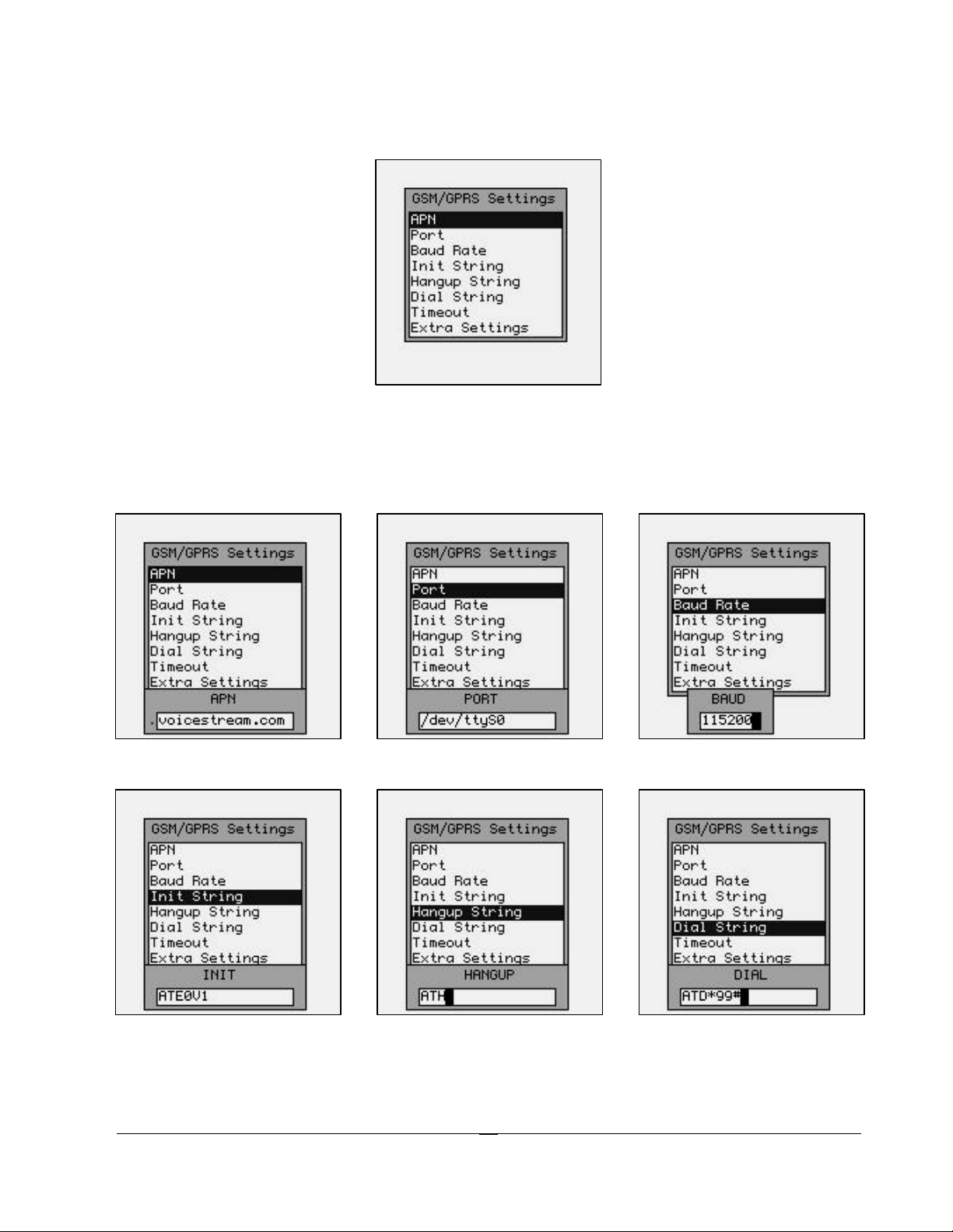
To review the GSM/GPRS settings, use the M7100 Menu System and select “Network Setup >
Net I/F Settings” and see the settings main screen.
The settings are selected by highlighting the proper item and hitting the [ENTER] key. The
information below is an example of how the unit might be set, your settings may be different.
Contact your local GSM/GPRS cellular service provider for information on these settings.
18
Page 23
Typical Values for the “GSM/GPRS Settings”:
APN – Access Provider Name
The character string specifying the cellular service provider (e.g. internet2.voicestream.com).
Port – Linux port name
This is a character string specifying the port name (usually “/dev/ttyS0”).
Baud Rate – Transmission Baud Rate
This is a character string specifying the baud rate (usually 115200).
Init String – Initialization String
The character string sent to the internal GPRS modem card prior to initiating a call.
Hangup String – Disconnectio n String
The character string sent to the internal GPRS modem card when it disconnects from a call.
Dial String – Dialing string
The character string sent to the internal GPRS modem card to initialize dialing of the call.
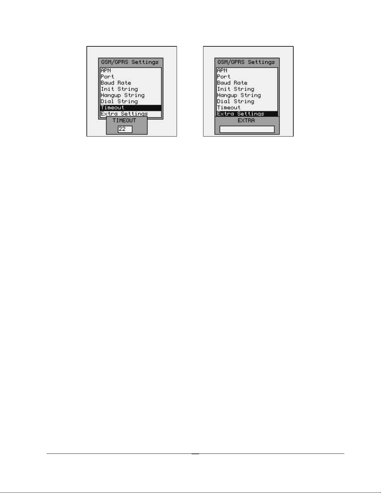
Timeout – Connection Timeout value
This is a numeric string that determines the amount of time (in seconds) to wait for the call
to connect.
Extra Settings – Extra settings string
This is a character string that is sent to the internal GPRS modem card prior to initiating a
call that may be used in special circumstances. One example is sending manufacturer
specific startup strings.
19
Page 24
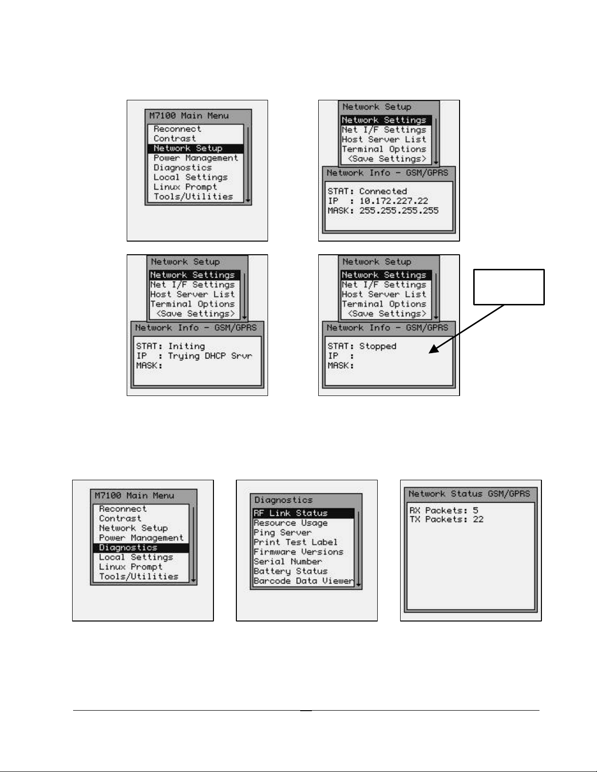
Failed!
To determine if the GSM/GPRS card is functioning properly, use the M7100 Menu System and
select “Network Setup” and one of the following screens should appear:
Connection
If the screen does not say “STAT: Connected” then you are out of range of a GSM/GPRS
Cellular Network, or you have the GSM/GPRS modem settings wrong.
To determine the amount of data being sent by the GSM/GPRS card, use the M7100 Menu System
and select “Diagnostics > RF Link Status” and see the “Network Status GSM/GPRS”.
GSM/GPRS Error Messages
There are numerous error messages that may appear. These error messages are logged on the
M7100 by the “syslog” system and stored in the volatile file named “var/log/messages”.
20
Page 25
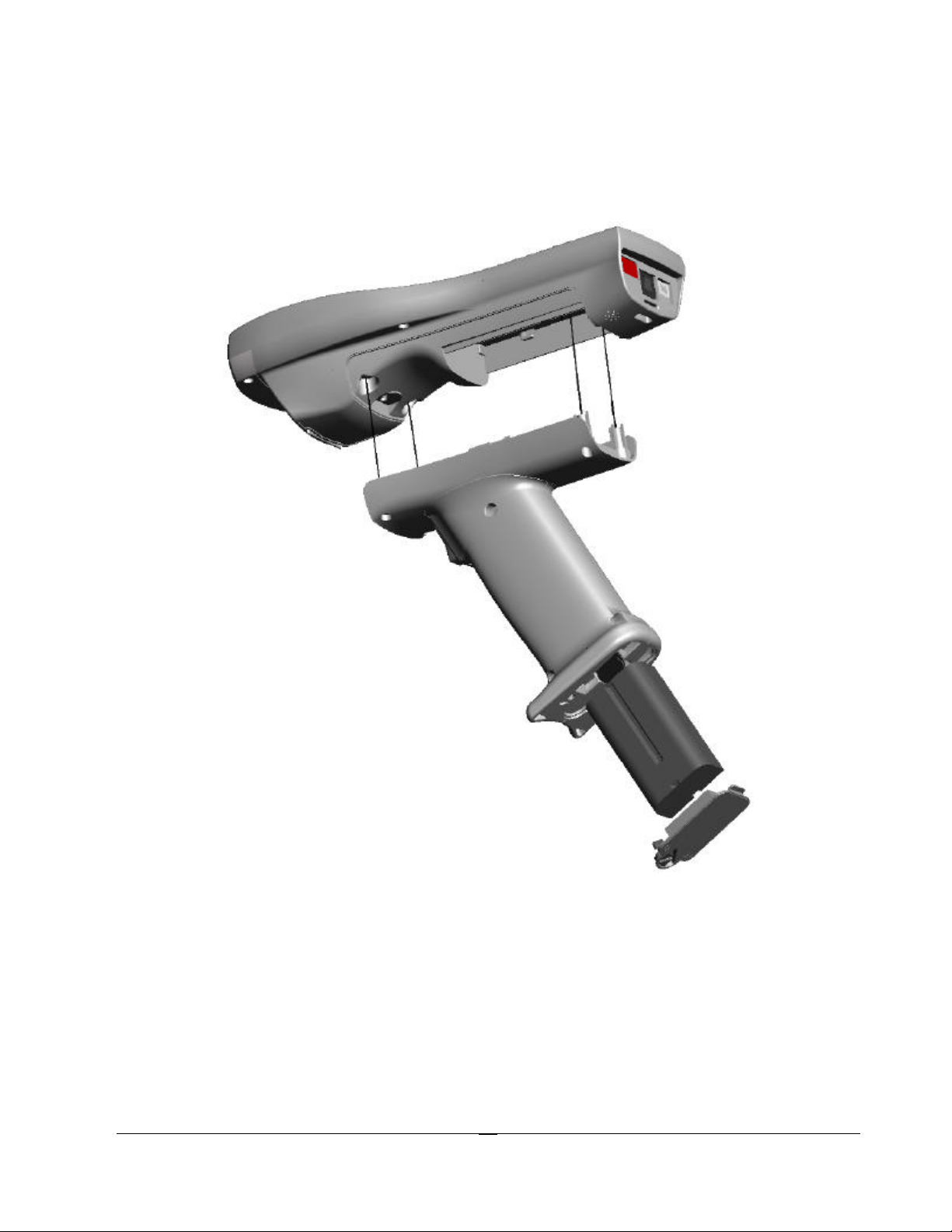
The Optional M7100 Handle
The M7100 has an optional “pistol grip” style handle for users who prefer the point and shoot
style. The M7100 handle is secured to the M7100 handheld terminal by 4 screws. The battery is
then relocated in the handle for easy change-out.
Installing the Optional M7100 Handle
To install the M7100 handle, remove the M7100 battery cover and store in a safe place. Remove
the M7100 battery and set it aside. Remove only the 2 screws in the bottom of the battery
compartment. The M7100 Handle comes with the necessary 4 screws to secure it to the M7100
unit. Do not over-tighten the 4 screws. Once the handle is securely fastened, insert the battery
into the bottom of the handle with the contacts towards the M7100 handle. The battery is held into
place by the spring latch. Install the battery handle door on the bottom of the handle. Never use the
M7100 handle without the battery door in place.
21
Page 26
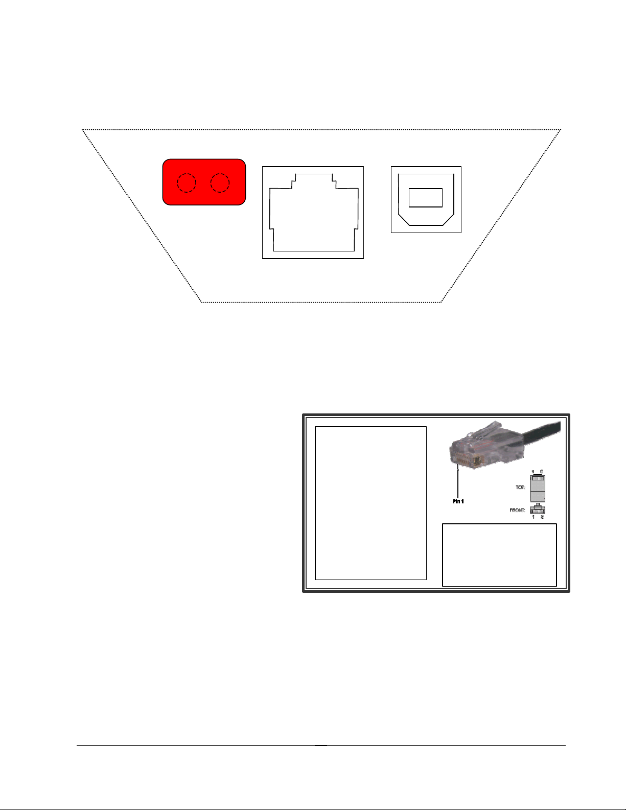
Note:
A standard 8
connect the M7100 to
chart and example on
he right to determine
4. GND
The M7100 Communications Ports
The M7100 has three types of communications ports on the bottom of the unit. The three ports are
shown here.
4 3
1 2
10 9 8 7 6 5 4 3 2 1
Description of the Infra-Red Detector Array Port (IrDA)
1. IrDA in (right side of window)
2. IrDA out (left side of window)
Description of the RJ-45 10 Pin Connector (RS-232)
1. 5 VDC (out to handheld tethered scanner)
2. RxD (in to terminal)
3. TxD (out from terminal)
4. RTS (out from terminal)
5. GND
6. Battery Charge (in to terminal)
7. CTS (in to terminal)
8. UDC+ (USB data +)
9. UDC – (USB data -)
10. Battery Out (from terminal)
Note: the Battery Out is only active when the unit
is set to IrDA w/RS232 Scanner or IrDA w/RS232
Comms
Ethernet connector
can be used to
an RS-232 serial port
printer. In this case
the 2 outside pins (1
and 10) are not
connected. Use the
t
-pin
Description of the USB Type II Connector (Slave only)
1 2
1. RxD (in to terminal)
2. TxD (out from
terminal)
3. RTS (out from
terminal)
1. 5 VDC
2. Data -
3. Data +
4. GND
22
Page 27
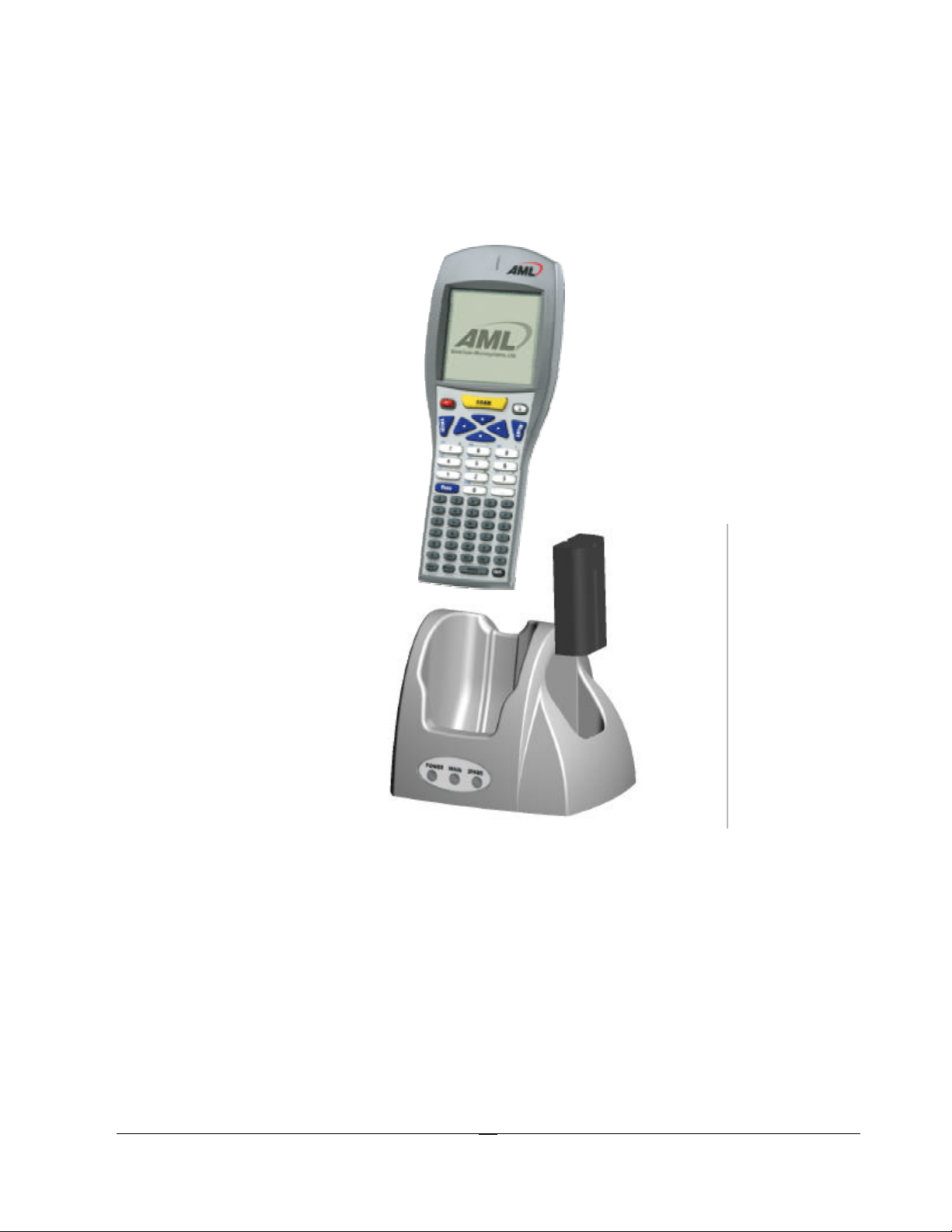
The M7100 Cradle
The M7100 Handheld Terminal has available, an optional charging and communications cradle.
The cradle automatically charges the M7100 battery while it is resting in the cradle. The cradle
also includes an extra slot to charge a spare battery. The M7100 cradle can accommodate the
M7100 with or without the optional M7100 handle.
The M7100 Cradle has three indicator lights:
POWER - Indicates that the M7100 Cradle is plugged in.
MAIN - Indicates the M7100 main battery is charging.
SPARE - Indicates the spare battery is charging.
When the battery charging LED is red, the battery is charging. When the battery charge LED is
green the battery is fully charged. A fully discharged battery takes about 6 hours to completely
recharge.
23
Page 28
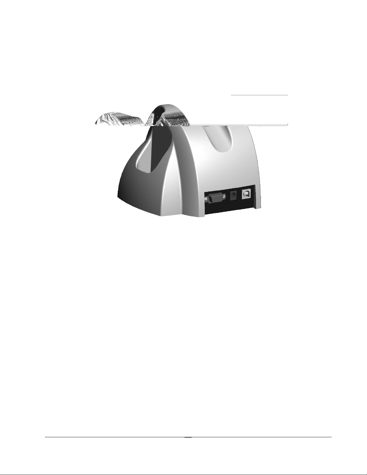
The M7100 Cradle’s Communication Ports
The M7100 handheld terminal has 2 different styles of communications ports, RS-232 (RJ-45) and
USB (Type II). The M7100 Cradle also has 2 communications ports, RS-232 (DB-9) and USB
(Type II). The M7100 Communications Cradle uses a standard RS-232 (DB-9 Male – DB-9
Female) cable.
Both communication connectors on the back of the M7100 cradle are wired “straight through”.
This means that the communications settings on the M7100 handheld terminal will determine the
settings on the communication cradle. The M7100 Cradle has no internal or external settings that
can be changed.
The slower RS-232 communication port is primarily used for uploading and downloading of data
files to the M7100 Batch handheld terminal. File transfers for the M7100 RF handheld terminal
can be done using FTP. For more information on FTP see the “FTP” section of this manual.
The high speed USB data port is used to load a new or updated operating system into the M7100
handheld terminal only. Use the AML USB Flash utility software to load the operating system.
DB-9 Pin out (RS-232)
1 – DCD (Data Carrier Detect) 6 – DSR (Data Set Ready)
2 – RXD (Receive Data) 7 – RTS (Request To Send)
3 – TXD (Transmit Data) 8 –CTS (Clear To Send)
4 – DTR (Data Terminal Ready) 9 – NC (No Connection)
5 - GND (Signal Ground)
24
Page 29
Chapter
3
W
The M7100 RF Server Login
This chapter describes the login functions of the M7100
terminal. It also describes using Telnet and Terminal
Emulation support.
arning: If the M7100 Handheld Terminal has improper security and/or
network settings, the terminal will fail to connect to any network devices.
For help see the Network Settings section of this manual.
The CommandLink™ Software
The CommandLink™ software allows a Windows based PC
to become an RF server. An RF server is a master control PC
that tells the M7100 handheld terminal what to display and
what to do with collected data. If your network already has
an RF server then you may choose to login into that server.
Many servers use a Telnet session to connect them to their
client devices. By default, the M7100 starts a telnet session
when it is first turned on. For more information about telnet,
see the Telnet section of this chapter.
Wait WLAN
The following screen shows the M7100 handheld terminal waiting to find a Wireless
Local Area Network (WLAN).
25
Page 30
If there is not a wireless Access Point (AP) for the handheld terminal to connect to, then
the terminal will not proceed past this point. For help in determining the presence and
strength of an Access Point’s transmission see the Network Diagnostics section of this
manual.
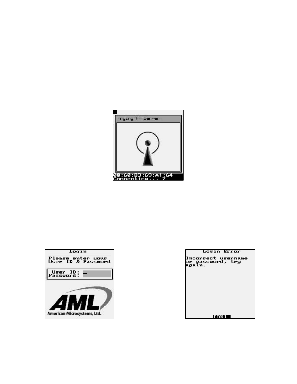
Connecting
The following screen shows the M7100 handheld terminal connected to an Access Point.
The MAC address number for the access point is displayed at the bottom of the screen.
After the M7100 handheld terminal connects (associates) with an access point, it attempts
to connect to an active CommandLink™ Server.
Note: If there is not an RF Server active for the M7100 handheld terminal to connect
to, then the terminal will not proceed past this point!
Login
The following graphic shows a typical login screen for the CommandLink™ RF server. If
you are using your own server, the login screen will be different. For help in determining
the presence of a CommandLink™ Server see the CommandLink™ documentation.
If the User ID or Password is not listed on the CommandLink™ database a Login Error
screen will appear.
26
Page 31

Applications
If you are using the CommandLink™ software, and the proper User ID and Password are
entered, then the Applications Menu is displayed. These are the programs that are
available on the CommandLink™ Server for this user. Other users may see other
programs depending on the settings in the CommandLink™ Administrator.
Additional programs can be created and modified by using the CommandLink™
Developer. Refer to the CommandLink™ documentation for instructions on how to use
the CommandLink™ software.
Telnet
For users who have their own Telnet applications, the M7100 handheld terminal can be
setup to simply run a telnet session.
In the above examples, it was assumed that the M7100 would be connecting to a
CommandLink™ RF server. If you would like to connect to your own telnet server, the
procedure is exactly the same. To run your telnet session you would simply enter the IP
address of your telnet server. An instruction on setting the IP address is explained under
the section “Connection Settings” of this manual.
Once the M7100 handheld terminal has successfully attached to a wireless network, it
automatically attempts to start a telnet session. The server address and parameters for
making this connection are listed under the Connection Settings menu of the M7100
handheld terminal.
Switching Virtual Consoles
The LCD screen and the keyboard are collectively referred to as the console. To let you
interact with several applications all at once, the M7100 permits multiple sessions to be
run concurrently on consoles by means of virtual consoles. The virtual consoles are
defined as follows:
Console 1: Menus
27
Page 32

Console 2: Communications Session or User Program
Console 3: Battery Warnings
Console 4: Second Telnet Session
Console 5: Linux prompt
Console 6: User Defined
Console 7: RESERVED
Console 8: User Defined
Console 9: RESERVED
Each virtual console is running a different foreground application that uses the entire
screen. The keyboard is attached to the virtual console that's currently visible. You can
switch from one virtual console to another - and thus from one application to another - by
entering the following key strokes.
To switch to a different console, press the [Alt]
then [Func] and a number key corresponding to
the Console number. The keys should be pressed
one key at a time, not all at once.
Terminal Emulation
The M7100 handheld terminal has three types of terminal emulation software installed as
default. They are amlterm, VT100 and VT220. There is also a Custom option which is
described later.
The amlterm terminal emulation software is specifically designed to work with the
CommandLink™ software. The CommandLink™ software controls the functionality of
the terminal from the CommandLink™ RF server. The CommandLink™ RF server runs
on a Windows based PC connected to the same LAN as the access points. In this mode
the CommandLink™ RF server controls all of the terminal’s functions.
The VT100 and VT220 terminal emulation is for other types of RF servers. When using
these two terminal emulation software types, the menus change to allow the terminal to
be setup manually to perform custom features such as font size, scrolling options and
virtual display size.
The Custom option allows you to set a custom terminal name for the M7100 which will
be sent to the server during connection. The terminal emulation will still be set to
VT220.
The expanded memory version of the M7100 supports 5250 and 3270 terminal emulation
with optional software. Custom screen mapping and keyboard redefinitions are also
possible with this optional software.
28
Page 33

The M7100 has a built -in feature which makes it easy to see when the terminal is out of
range of an access point. When the M7100 goes outside of RF coverage, the following
screen appears. When the operator goes back into RF coverage, the “Out of Range”
screen will automatically disappear and return the operator to where they left off. This
feature is only available when using the built -in terminal emulations described above.
Instructions on selecting the terminal emulation type are described in the Connection
Settings section of Chapter 4.
Updating Firmware
The M7100 has a built-in web server function which makes updating the firmware very
simple. If your M7100 handheld has a firmware version of 1.0.1 or later, you can flash
the handheld over the RF network using a standard web browser. The files will be
transferred to the M7100 unit over the RF link and no cables or other software is
required. For units with an earlier firmware version, the USB flash utility is required
which can be downloaded off the AML website.
To upgrade the M7100 firmware, the handheld must be on, and connected to the same
network as your PC. Open your internet web browser (for example, Internet Explorer)
and type the IP address of your M7100 handheld into the Address box. Once you have
successfully connected to the M7100 you will see a green AML screen (this is generated
and sent to your PC by your M7100 unit). Select the "Reprogram Device Firmware" link.
At the bottom of this page, you will see several file options. For each file type, use the
radio button to select the type of file being flashed, then attach the file using the browse
button (do not unzip the "rdiskxx.gz" file for this operation). Finally, click Submit to start
the process (do not turn the power off on your M7100 until the flash process is
completed). When finished, the unit will either create a green OK screen or a red error
screen based on the results. If there are errors, try sending the file again before power
cycling the unit. If the RF flash utility fails to re-flash the M7100 unit for any reason, use
the USB utility to re-flash the unit, available on the AML website (www.amltd.com).
Note: The latest firmware files can be downloaded off the AML website.
29
Page 34

Chapter
4
Y
The M7100 Menu System
This chapter describes the Main Menu functions of the M7100 Handheld
Terminal.
Main Menu
ou may access the menu system by pressing the [Menu] key on the M7100
handheld terminal. The menu screens pop-up in front of the currently displayed
screen. Only the items in the menu screens are active when the menu items are
displayed.
The menus can be navigated by using the up and down cursor keys. A selection is made
by pressing one of the two [ENTER] keys on the M7100 handheld terminal. The [ESC]
key will always exit the current menu.
Reconnect
The reconnect option forces the handheld to reconnect to the CommandLink™ RF server.
This is useful if the connection is stalled for whatever reason.
30
Page 35

Contrast
The contrast can be set by selection the “Contrast” function from the Main Menu. The
3(left) and 4(right) arrow keys can be used to fine-tune the contrast.
The scroll bar below the Main Menu window shows the current contrast level.
The [ENTER] key will save the changes to the permanent flash memory and [ESC] will
abandon changes.
31
Page 36

Network Setup
By selecting the Network Setup function from the Main Menu the wireless network
adapter can be configured. The “Network Connection Info” dialog box displays the RF
Status (RF) the current IP Address (IP), Network Mask (MASK) and the MAC Address
(MAC) of the wireless Ethernet card that is installed in the M7100. The RF Status is
described in more detail in the Diagnostics portio n of this manual.
The standard network settings are changed by hitting the [ENTER] key while the
Network Settings menu item is highlighted.
The user will see one of the three screens shown above. If the wireless local area
(WLAN) network has a Dynamic Host Configuration Protocol (DHCP) server attached to
the network, then the DHCP function can be used. To select the DHCP function, simply
use the arrow keys to highlight the DHCP button. If your network uses the BOOTP
protocol then highlight that button. Note that when using DHCP or BOOTP, several of
the items below are missing. This is because the DHCP server or the BOOTP server will
automatically assign these values. If the wireless WLAN does not use the DHCP or
BOOTP functions, then the user must type in the appropriate values for the M7100
handheld terminal to communicate.
Warning: These values are unique for each network and are assigned by your local
Systems Administrator. Improperly setting these functions or values will cause the
M7100 to fail to communicate and can cause problems with other network devices.
32
Page 37

Note: Enabling DHCP or BOOTP will cause the M7100 handheld terminal to take
slightly longer to establish a connection to the RF network due to the overhead involved
in obtaining network information from the server.
Radio Settings (WEP)
The Radio Settings allows the operator to set wireless network security settings.
The first radio setting is SSID (Service Set Identifier), a 32 character unique identifier
attached to the header of packets sent over a WLAN that acts as a password when a
mobile device tries to connect to the network. The SSID differentiates one WLAN
from another, so all access points and all devices attempting to connect to a specific
WLAN must use the same SSID (SSID’s are CASE sensitive)!
You can leave the SSID blank and the M7100 will match to any access point regardless
of its SSID as long as the WEP settings match.
Because an SSID can be sniffed in plain text from a packet it does not supply any
security to the network.
An SSID is also referred to as a Network Name because essentially it is a name that
identifies a wireless network.
33
Page 38

In the example above, “AMLBURNIN” was chosen for the unique SSID name. Your
unique name should be assigned by your local Systems Administrator.
The wireless security settings are referred to as WEP (Wireless Equivalent Privacy) can
be left un-enabled or can be enabled from this menu. It is HIGHLY recommended that
some sort of WEP standards be enabled in any wireless network. This information is
unique for each network and should be assigned by the local Systems Administrator.
The M7100 handheld terminal supports both 40 bit and 128 bit WEP key encryption.
Note that the number of key sets change according to which format is chosen.
The Key ID determines which key set is currently in use. Only the Key ID set selected
will be used, all other key sets are ignored.
34
Page 39

To modify an encryption key set simply highlight the appropriate key set. Note that the
number of key pairs will change depending on which encryption format you are using.
Note: Some manufacturers will call their 40 bit encryption 64 bit encryption or call their
128 bit encryption 160 bit encryption; in any case they are the same settings. Also some
manufacturers will number their keys 1 to 4; these keys match the 0 to 3 keys on the
M7100.
The key that is set MUST match, in exactly the
same sequence, of the key that is currently set
in the Access Points. The key on the access
point that is set must match the “Key ID” field !
The Mode setting determines what type of network is in use.
The Infrastructure Mode is for connecting the M7100 Handheld Terminal to a network of
access points. The Ad Hoc Mode is used for connecting the M7100 to a single access
point or a single radio card in a peer-to-peer network, such as a single laptop computer
for example.
35
Page 40

The Auth setting determines what type of network system you are using.
These two modes simply define how the above key sets will be used to encrypt the data
sent over the radio. Whichever mode is selected, the access point MUST be set to the
same mode for communications to take place.
The Power Save setting will force the radio card to turn off when not in use to save
power. If you experience connection problems, turn the Power Save feature off. Battery
life will be shortened with the Power Save feature shut off.
The Channel setting determines which channel the radio card will start to communicate
on. This should be set to the same channel as the access points.
36
Page 41

Radio Settings (WPA-PSK)
The M7100 supports both WPA-PSK (Pre-Shared Key) and WPA-EAP (Extensible
Authentication Protocol).
The WPA-PSK offers TKIP mode or AES-CCMP mode. The mode used must match the
network the M7100 is to communicate with.
The Shared Phrase must match the network the M7100 is to communicate with.
The Power Save setting will force the radio card to turn off when not in use to save
power. If you experience connection problems, turn the Power Save feature off. Battery
life will be shortened with the Power Save feature shut off.
37
Page 42

Radio Settings (WPA-EAP)
The WPA-EAP offers PEAP, TLS and TTLS mode. The mode used must match the
network the M7100 is to communicate with.
The Shared Phrase must match the network the M7100 is to communicate with.
The Username must match the network the M7100 is to communicate with.
The Passwd must match the network the M7100 is to communicate with.
The Infrastructure Mode is fo r connecting the M7100 Handheld Terminal to a network of
access points. The Ad Hoc Mode is used for connecting the M7100 to a single access
point or a single radio card in a peer-to-peer network, such as a single laptop computer
for example.
The Power Save setting will force the radio card to turn off when not in use to save
power. If you experience connection problems, turn the Power Save feature off. Battery
life will be shortened with the Power Save feature shut off.
The Channel setting determines which channel the radio card will start to communicate
on. This should be set to the same channel as the access points.
38
Page 43

Certificate Settings TLS
When using TLS you must store the proper certificates onto the M7100 handheld
terminal. The Certificates and Shared Phrase must match the network the M7100 is to
communicate with.
Certificates can be generated from most web browsers such as Mozilla or IE. Establish a
connection to your Certificate Authority and download a CA certificate in base64 format.
Save this file as "ca.pem". Then request to generate a client certificate in PKCS12 format
and save this file as "client.p12".
Remember what the phrase is for the certificate as that will need to be entered on the
M7100's configuration menu option.
On the M7100 series unit there should already be a "/jffs2/certs" directory, if not simply
create one. Then place both the “ca.pem” and “client.p12” files into that directory via ftp.
The ftp server running on the unit will require a user name and password to connect and
send over files;
Username: aml
Password: turk182
The Shared Phrase must match the network the M7100 is to communicate with.
39
Page 44

Host Server List
The Connection Settings determine how the M7100 Handheld terminal will communicate
to a host server over the RF network. When the M7100 Handheld terminal first powers
up, it tries to establish a connection to an RF network. If this is successful, it will then
start a Telnet session using the settings described in this section.
During this start-up process, the M7100 will look to see if multiple host servers have
been defined in the Host Server List. If only one server is defined, the M7100 will
proceed to attempt to establish a connection with that server. However, if more than one
host server has been defined, the user will be prompted to choose a host server name
from a list of servers.
Simultaneous Hosts Connection
The M7100 will allow for two simultaneous telnet sessions. These sessions are running in
the background on separate virtual consoles (see Switching Virtual Consoles in the
previous chapter). In order to use this feature there must be two and ONLY two servers
listed in the Host Server List.
When the operator is presented the list of hosts to connect to, there will be an extra option
of connecting to both. If only one host is selected, then only one connection is made. If
the “Connect to Both” option is selected then both sessions will be active.
40
Page 45

The first session is on virtual console 2 and can be accessed by pressing [Alt] then [Func]
then [2]. The second session is on virtual console 4 and can be accessed by pressing [Alt]
then [Func] then [4].
Multiple Hosts
If multiple host have been defined, and a user wishes to select a different host, then the
user would hit the Menu key then Reconnect and the host list will be re-displayed. The
user should then simply select the host they wish to connect to.
When more than two hosts are defined, the
“Connect to Both” option is not available.
When defining hosts servers, names can be any combination of letters and numbers, up to
15 characters long. The Port setting determines which network port the M7100 handheld
terminal will try to connect to. The default setting is Port 23 but some network systems
require this to be changed.
The “More Host 1 Options” function allows the user to input special log-in data. For
more details on this function see the description in the next section.
You can assign up to 8 different host profiles in the M7100. By using the arrow keys you
can scroll down to enter the information about additional hosts.
If the AML CommandLink™ RF software is being used with your network, then the IP
address of the CommandLink™ RF server must be supplied. This is the IP address of the
computer where the CommandLink™ Communicator is running.
The M7100 Handheld terminal has optional Terminal Emulation software available that
enables it to communicate directly with most host systems including IBM mainframe
(TN3270) and IBM AS400 (TN5250) systems. This software has many more features
than described in this manual.
41
Page 46

Hosts Log-in Options
For each host server listed, you can add special options to make logging into the hosts
easier. While this feature makes it easy to log-in to a server, it also makes the server less
secure. The information entered in this screen is unique to each host system and must be
supplied by the local systems administrator.
In this example, the Log-in Search string (Lgn Srch:) is “login:”. This means that when
the Host Server sends this text string to the M7100, it will reply with exactly what is in
the Log-in Reply string (Lgn Rply:) which is “rfgun\n” (more information about the “\”
switches is listed below).
The Password Search string (Pwd Srch:) is “Password:” and the Password Reply string
(Pwd Rply:) is “1JJ2ST\n”. Remember that these strings must match exactly including
upper and lower case characters or the system will not work.
The Command Search string (Cmd Srch:) is “hpux $” which is a prompt from the server
for what command to execute. In this example the M7100 would respond with the
Command Reply string (Cmd Rply:) which is “./inventory\n”.
You can enter straight HEX data by preceding it with the customary “0x” as in 0xFF for
the HEX value of FF. You can send multiple HEX values by adding additional HEX sets
as in 0x120xBF0xFF for the HEX value of 12 BF FF. Octal values use the customary
\012 which is 12 octal.
Once the M7100 encounters the “search strings” for the first time, it will send the
appropriate response. If the M7100 encounters the “search string” again during the same
session, it will not respond. This is so the search string characters can be used in normal
screen displays.
The \n character string sends the new line (linefeed) character and is shown after each
reply string above. The \r character string sends a Carriage Return command and is not
shown above. In order to send a single backslash (\) character, you must enter two
backslash characters in a row \\.
These options can be set for each host server listed. You can input the same host server
multiple times, each using different log-in options.
42
Page 47

Terminal Options
The Term setting determines what terminal type the M7100 will emulate. The default
setting is standard “VT100”. If you are using CommandLink™ software, set the Terminal
type to “amlterm”.
Note: When using amlterm with CommandLink™ the optional features are controlled
by the CommandLink™ server and are not selectable on the M7100 unit.
The currently available terminal emulations are “amlterm” which is only used with the
CommandLink™ application, “vt100” and “vt220” terminal emulations typically used
with UNIX based servers and “tn5250” terminal emulation typically used with IBM
AS/400 systems. Other terminal emulation types and features are available as optional
software packages.
Terminal Emulation - amlterm
The “amlterm” setting is used with the AML CommandLink™ software. The “amlterm”
emulation is a super-set of vt100 terminal emulation with special feature added to support
a CommandLink server.
The Local Echo feature enables or disables displaying of characters sent to the host
system. The default setting for most host systems is Local Echo disabled (unchecked).
43
Page 48

Terminal Emulation – vt100 / vt220
The “vt100” terminal emulation is typically used for older server applications that do not
support vt220 terminal emulation. It is recommended that the “vt220” emulation be used
when possible.
If a different terminal type is selected, then the optional features for that emulation are
displayed. These features allow you to customize how the M7100 handheld terminal will
display the information from your RF server.
Note that you can “scroll down” to access all the features available when using a specific
terminal type. Also when you “check” some features, more options appear that are
specific to those functions.
When using the vt100 or vt220 settings the default settings are usually sufficient. Some
systems will require modifications to these settings.
The Font function allows you to select a custom font size which will change the amount
of information displayed on the screen.
44
Page 49

The “Legacy” font is specifically designed for legacy applications where the screen size
has been designed to work on a 16 row by 21 column screen size. Many older terminals
were designed with this screen size only.
When using Terminal Emulation you can not mix different size fonts on the same
terminal screen.
If the Disable Scrolling check box is checked the screens will lock into the upper left
hand corner of the display regardless of how much information is sent to the screen. This
box is unchecked by default.
45
Page 50

When scrolling is disabled by un-checking the "Disable Scrolling" option, two screen
location options are available. "Screen Loc x" and Screen Loc y" set the position of the
M7100 viewable area relative to the upper left hand corner of the virtual tn5250 24x80
screen. This allows the user to "lo ck" the location of the viewable area within the entire
virtual screen.
Example: If the terminal was set for the Medium font, the screen can only show 20
columns and 20 rows. With scrolling disabled and "Screen Loc x" and "Screen Loc y"
both set to 0, the M7100 screen will always display the 20 top rows and the 20 top
columns.
If the Virtual 24x80 check box is unchecked all the text sent to the terminal will be forced
into the current display size (which depends on the font size selected). Most terminal
emulation screens are written for a 24 column by 80 character display size so this box is
unchecked by default.
If the Follow Cursor check box is checked then the screen will scroll to wherever the
cursor is on the display. This box is unchecked by default.
46
Page 51

The Col Shift function determines how many columns the display will move each time
the Shift <arrow> keys are used. This allows the operator to “pan around” the currently
displayed screen. Use the left 3and 4right arrow keys to change this setting.
The Row Shift function determines how many rows the display will move each time the
Shift <arrow> keys are used. This allows the operator to “pan around” the currently
displayed screen. Use the left 3and 4right arrow keys to change this setting.
47
Page 52

Note that we have “scrolled” down to the bottom of the screen and do not have the
Virtual 24x80 function selected.
The Wraparound function tells the terminal to “wrap” long text strings onto multiple lines
on the M7100 screen. This can be very confusing when the data was originally formatted
for a 24x80 text screen. This option is unchecked by default.
The Swap Bksp & Del function will swap the meaning of the backspace arrow [? ¦ ] and
the Delete key [Ctl] then [? ¦ ]. This is used primarily to speed up keyboard entry when a
delete is used more often than backspace.
48
Page 53

The Parse `` as Esc function is for certain Windows servers that can not accept the Esc
key sequences. If this box is checked, the M7100 will send `` instead of Esc for these
sequences.
The ENQ: function will allow the M7100 to respond with a specific ENQ Answerback
String whenever the host sends the unit an ENQ command. This string can be anything
like the terminal name or terminal number.
The Linefeed Mode function, when selected will add a Carriage Return to each Linefeed
character received from the host. Some host systems do not send the customary CR LF at
the end of each line. If a CR is not received, the M7100 will not start from the left hand
side of the screen when a new line is started.
49
Page 54

The Map Ins as dash function allows for a quick way to insert a dash character (-) instead
of the rarely used [Ins] key function. This is useful for quickly typing part numbers that
include the dash character (e.g. 123-456-789).
The F5: function tells the M7100 what character string to send back to the host when the
F5 key is pressed. Some host systems want this to be “esc0t” and some systems expect
the “esc[15˜” or “esc[16˜” string. Use the right and left arrow keys to make the selection.
The ANSI Colors function allows the terminal to better interpret ANSI color commands
and translate them into the grayscale screen on the M7100. This function is typically
checked when using a Windows based server like “Windows Terminal Server”.
50
Page 55

The Null Padding function is required on most server systems that use the traditional
vt100 and vt220 emulations. The null padding can cause an error on some Windows
based servers. If you are experiencing problems with a Window’s based Terminal
Emulation server, try un-checking the null padding option.
Function Key remapping allows the user to alter the codes sent to the host computer
when a function key is pressed. The “Func Key Remapping” box must be checked to
modify the function keys. If the “Func Key Remapping” box is unchecked, the M7100
will simply send the standard VT100/VT200 function codes to the server, when a
function key is pressed.
If the “Func Key Remapping” box is checked, then the user can select the “Define
Function Keys” item. The following screen will appear (below left). If you select one of
the function keys you will be able to edit the string that is sent to the server when that key
is pressed (below right).
51
Page 56

The string shown here will send a “!#EOJ” followed by a carriage return to the host
computer system, when the F6 key is pressed.
The \n character string sends the new line (linefeed) character and is not shown above.
The \r character string sends a Carriage Return command and is after the string shown
above. In order to send a single backslash (\) character, you must enter two backslash
characters in a row \\.
You can enter straight HEX data by preceding it with the customary “0x” as in 0xFF for
the HEX value of FF. You can send multiple HEX values by adding additional HEX sets
as in 0x120xBF0xFF for the HEX value of 12 BF FF. Octal values use the customary
\012 which is 12 octal.
The new function key values are saved in a setup file on the M7100. This setup file can
be copied to other M7100 so that they can also have the same function key settings. The
name of this file is “settings.keyboard” and it is located in the “/jffs2” sub-directory.
The <Save Settings> function allows the new network settings to be permanently stored
in the M7100 handheld terminal’s non-volatile memory.
52
Page 57

Terminal Emulation – tn5250
The “tn52550” terminal emulation is typically used for IBM AS/400 server applicatio ns.
The AML tn5250 TE is designed to be a basic 5250 emulation. If optional features are
required, it is recommended that either the Connect PowerNet TwinClient emulations or
the Stay Linked emulation be used.
If a different terminal type is selected, then the optional features for that emulation are
displayed. These features allow you to customize how the M7100 handheld terminal will
display the information from your RF server.
The Font function allows you to select a custom font size which will change the amount
of information displayed on the screen. The Huge font set is not available with the tn5250
terminal emulation.
53
Page 58

The Legacy font is specifically designed for legacy applications where the screen size has
been designed to work on a 16 row by 21 column screen size. Many older terminals were
designed with this screen size only.
When using Terminal Emulation you can not mix different size fonts on the same
terminal screen.
The Auto Reset on Err function resets the connection if an error occurs. When the Auto
Reset is selected you can set a delay time to display error messages.
The Field-lock Cursor function locks the cursor to the last displayed field.
54
Page 59

The Disable Scrolling locks the cursor to the upper left screen location. If Disable
Scrolling is not checked then you can set the Follow Cursor function which moves the
cursor to the current input field.
The Col Shift function determines how many columns the display will move each time
the Shift <arrow> keys are used. This allows the operator to “pan around” the currently
displayed screen. Use the left 3and 4right arrow keys to change this setting.
The Row Shift function determines how many rows the display will move each time the
Shift <arrow> keys are used. This allows the operator to “pan around” the currently
displayed screen. Use the left 3and 4right arrow keys to change this setting.
The Swap Bksp & Del function will swap the meaning of the backspace arrow [? ¦ ] and
the Delete key [Ctl] then [? ¦ ]. This is used primarily to speed up keyboard entry when a
delete is used more often than backspace.
The Truncate Scans function will truncate any scanned bar code that is larger than the
input field.
55
Page 60

The Display Name function allows the user to program a specific terminal name. This
name is then transferred to the host when the terminal logs onto the system.
If you do not save your settings they will be lost when
you exit the Network Settings screen.
The terminal options will only be made permanent if you
do a Save Settings, otherwise they are lost when the
unit is turned off and on.
56
Page 61

The <Restart Network> function allows the new network to be restarted with all the
new settings made in the above menus.
If an active host server is found, the M7100 will display the log-in screen of that server.
If the host server can not be found, the M7100 Menu System will continue to be
displayed.
Power Management
The “Power Management” function allows the user to make changes in the way the
M7100 handheld terminal conserves power consumption.
Warning: You can disable any of the Power Management timers by setting
a value of zero (0). However, this will increase battery usage and decrease
battery life.
The “Sleep Timer” determines how long in minutes before the M7100 handheld terminal
will turn off the display, halt the current program activity and turn off the radio card. A
red LED on the upper left hand corner flashes while the M7100 is in sleep mode. You can
activate the terminal at any time by pressing any key including the power key. Press and
hold the power key to turn off the unit completely.
57
Page 62

When the M7100 goes into Sleep Mode, it turns off the
internal radio card. On some host systems, this causes
the current telnet session to be closed.
Many users find it better to set the Sleep Timer
to zero to prevent closed connections.
Note: The power key wake-up feature is only available on units with Decoder version 2.0
or later. The Decoder can only be re- programmed at the factory.
The “Backlight on Boot” function sets if the backlight will be lit when the unit is first
powered on.
The “Backlight Timer” determines how many minutes the M7100’s backlight will stay on
after “power on” or when the backlight key is pressed.
The PowerOff After Sleep timer is how many minutes the M7100 will wait, after the
Sleep Timer has activated, before shutting off the M7100 completely.
The “Wakeup on All Keys” function allows the user to have the unit “wake-up” when
any key on the keyboard is pressed. This is not recommended if the user is putting the
unit into the optional M7100 holster.
If you do not save your settings they will be lost
when you exit the Power Management screen.
The Power Management options will only be
made permanent if you do a Save, otherwise
they are lost when the unit is turned off and on.
58
Page 63

Diagnostics
The “Diagnostic Menu” has several powerful functions that can help pinpoint a variety of
network problems. The Diagnostic menu can be used to determine connectivity to the
network as well as connectivity to the server or host computer.
Network Status
The “Network Status” function allows the operator to test the Network Connection
Status. This is the most important diagnostic tool available to the operator.
The “RF Quality” bar graph shows the RF signal strength of the closest Access Point. If
59
Page 64

The “WLAN:” shows the current connection status reported by the internal RF card. This
status can be a very useful tool to determine if an RF connection is being made. The
description of this status is shown below:
Disabled This normally means that either the
network settings are being changed or the
RF card is malfunctioning or not making
contact.
Searching This can appear in these types of
situations:
1. No access point at all.
2. There is no RF coverage in this area.
3. The SSID is set wrong.
4. The WEP is wrong and the authorization
is set to SharedKey.
Connected - Ad Hoc This is when the M7100 is connected to
one and only one RF card in a peer-to-peer
mode (like a laptop PC RF card).
Connected - AP Normally, this means everything is OK and
the user should be able to communicate. It
is possible that the WEP settings are
wrong but the authorization is set to
OpenSystem.
Out of Range This means that there was a functioning
connection and the unit has gone out of
range.
The “MAC: 00:0F:66:19:32:61” is the MAC hardware address of the currently
connected Access Point! This address is unique to each Access Point used. In Ad-Hoc
mode this will display “N/A – Ad Hoc Mode”.
The “TX Rate” shows the speed in Mega-Bits per Second (Mbps) that the unit is
currently transferring data. The transfer speed will start at 11 Mbps and “fall-back” to
lower speeds depending on the RF strength and quality. This “fall-back” is automatic and
can not be set by the operator. If you find this speed to be unacceptably low, you must
improve the wireless RF network coverage in your area.
60
Page 65

The “RF Strength” function can be used to test
the RF coverage of a wireless RF local area
network. Simply put the M7100 handheld
terminal in “RF Strength” mode and walk in the
area you want to have RF coverage, and you can
quickly see areas with poor RF coverage.
Note that this
is a very bad
connection!
This unit is connected to
the Access Point with
a MAC address of:
00:02:2D:3E:AD:D8
at 5.5 Megabits per Second.
Note that this
is a very good
connection!
This unit is connected to
the Access Point with
a MAC address of:
00:40:96:58:8C:25
at 11 Megabits per Second.
61
Page 66

Resource Information
The “Resource Information” function shows the memory usage and CPU allocation at the
current time.
The above display shows 72% of the virtual disk memory used, 52% of the Journaling
File System (user) memory used and 95% of the static RAM memory used. The Linux
operating system uses as much of the free static RAM as possible so this number is
usually very high. As more RAM is needed for other applications, Linux will
dynamically re-allocate the memory to make more RAM available for the application.
The CPU usage is usually low because there are no processes utilizing the processors
time while in the menu mode.
Ping Server
The “Ping Server” function is a very powerful tool to test connectivity through the
wireless RF network.
When the “Ping Server” function is selected, the dialog box includes a section to type an
IP address on the bottom. Once a valid IP address is typed hit [ENTER] to start the
“pinging” process. Press the [ESC] key when finished.
62
Page 67

The “Ping Status” screen will show the M7100 handheld terminal trying to contact the
listed IP Address. Once the connection is made the M7100 Handheld Terminal will
continuously send packets of data to time the connection speed in milliseconds (ms). The
“Ping Status” screen will display the results of the ping process.
If the M7100 handheld terminal does not receive a response to the pinging, then the
above (right) screen will appear. It is very important that the M7100 handheld terminal is
able to communicate with the CommandLink™ RF communicator server PC. The “Avg”
transfer time in milliseconds and “PLoss” percentages is very important. High ping
transfer rates or failure to communicate with the server will make the CommandLink
programs un-usable on the M7100 handheld terminal.
The “Ping Server” function can be used to ping Access Points and other computers on the
wireless local area network. This is a useful tool in determining wireless network
connectivity. Like all computer equipment, the M7100 Handheld Terminal can not ping
to other equipment that isn’t connected to the currently specified local area network.
63
Page 68

Print Test Label
The “Print Test Label” function allows the operator test a serial or IrDA (Infrared Diode
Array) printer through the serial or IrDA port on the bottom of the M7100 handheld
terminal.
There are two types of printers supported in the “Print Test Label” sub-menu function.
The M7100 does support almost any type of serial printer, the two printers shown are for
testing purposes only.
If the M7100 handheld terminal is setup for serial printing, it sends the data to the serial
port (see Local Settings Menu for communications options). If the M7100 finds the IrDA
printer it will identify it and, if possible, and print a test label.
64
Page 69

Firmware Version
The “Firmware Version” function displays the information about the M7100 handheld
terminals firmware version and the date and time it was created.
Serial Number
The “Serial Number” function displays the information about the M7100 handheld
terminals serial number if your unit supports this function.
Battery Status
The “Battery Status” function displays the current battery level.
65
Page 70

When the M7100 handheld terminal’s battery is completely depleted, a “Battery Low”
error screen is displayed signaling that you must replace the battery or place the unit in
the charger for charging.
Barcode Data Viewer
The “Barcode Data Viewer” function displays the actual data acquired by the bar code
scanner including non-printable characters. The display shows both the printed values as
well as the ASCII equivalent value scanned. Hit the [C] key to clear the screen and hit the
[Esc] key to quit.
66
Page 71

Ping USB Server
The Ping USB Server function allows you to detect a USB server connected to the USB
port.
Hardware Tests
The Hardware Tests function performs tests on the various M7100 hardware.
Note: These hardware tests are for our own internal
testing and may, or may not, display as failed for the
end user, even though the unit is running fine.
67
Page 72

Local Settings, Laser & CCD Only
Note: For instructions on setting the 2D Area Imager see Local Settings, Imager Only.
The “Local Settings” function sets much of the M7100 handheld terminal’s internal
hardware and software.
Barcode Options
The “Barcode Options” function allows you to make changes to the way specific bar
codes are scanned by the internal scan engine.
Symbology Settings
The “Symbology Settings” function allows you to make changes to each individual bar
code.
68
Page 73

Setting the Code 39 Bar Code
The individual bar codes can be enabled and disabled by hitting the [Space] key. Only
enabled bar code symbologies can be modified. To modify a bar code symbology hit
the [ENTER] key while the bar code name is highlighted.
CODE 39 DECODER
ON* Enable reading Code 39 bar codes.
OFF Disable reading Code 39 bar codes.
FULL ASCII
ON Enable the Full ASCII Extension to Code 39. This allows the scanner to
read upper and lower case characters as well as extended special
characters.
OFF* Disable the Full ASCII Extension to Code 39. This sets the reader to the
standard Code 39 mode.
MOD 43 CHECK DIGIT
ON Enable the Mod 43 Check Digit for Code 39. When this option is enabled,
only Code 39 labels that contain a valid check digit will be read.
OFF* Disable the Mod 43 Check Digit. Check digit verification will not be
performed.
SEND CHECK DIGIT
ON Transmit the Mod 43 Check Digit with the bar code data. Requires the
“Mod 43 Check Digit” option above to be set on.
OFF* Do not transmit the Mod 43 Check Digit.
CONCATENATE MODE
69
Page 74

ON Enable Concatenate Mode. The concatenate mode allows the M7100
handheld terminal to accumulate multiple bar codes in its buffer and then
sends them to the computer just like they were a single bar code. When a
Code 39 label containing a leading space is read, the M7100 emits two
short beeps and buffers the data without transmission. This process
continues until a Code 39 label without a leading space is read or 128
characters are buffered. A Code 39 bar code label that only contains a
single or multiple dashes (minus sign) will clear the buffer.
OFF* Disable Concatenate Mode.
Setting the UPC Bar Code
UPC DECODER
ON* Enable reading UPC-A and UPC-E bar codes.
OFF Disable reading UPC-A and UPC-E bar codes.
CONVERT UPC-E TO UPC-A
ON Convert all UPC-E labels to their UPC-A equivalents before transmission.
After conversion, the reader will follow the UPC-A programming options.
OFF* No conversions will be performed.
CONVERT UPC-A TO EAN-13
ON Convert all UPC-A labels to an equivalent EAN-13 format by inserting a
leading zero. After conversion, the reader will follow the EAN-13
programming options.
OFF* No conversions will be performed.
SEND UPC-A NUMBER SYSTEM
70
Page 75

ON* Transmit the UPC-A Number System character.
OFF Do not transmit the UPC-A Number System character.
SEND UPC-E NUMBER SYSTEM
ON* Transmit the UPC-E Number System character.
OFF Do not transmit the UPC-E Number System character.
SEND UPC-A CHECK DIGIT
ON* Transmit the UPC-A Check Digit character.
OFF Do not transmit the UPC-A Check Digit character.
SEND UPC-E CHECK DIGIT
ON* Transmit the UPC-E Check Digit character.
OFF Do not transmit the UPC-E Check Digit character.
Setting the EAN Bar Code
EAN DECODER
ON* Enable reading EAN-8 and EAN-13 bar codes.
OFF Disable reading EAN-8 and EAN -13 bar codes.
ZERO FILL EAN-8 TO EAN-13
ON* Add five leading zeros to EAN-8 labels. After conversion, the reader will
follow the EAN-13 programming options.
OFF No conversions will be performed.
71
Page 76

SEND EAN-13 COUNTRY CODE
ON* Transmit the EAN-13 Country Code.
OFF Do not transmit the EAN-13 Country Code.
SEND EAN-8 COUNTRY CODE
ON* Transmit the EAN-8 Country Code.
OFF Do not transmit the EAN-8 Country Code.
SEND EAN-13 CHECK DIGIT
ON* Transmit the EAN-13 Check Digit character.
OFF Do not transmit the EAN-13 Check Digit character.
SEND EAN-8 CHECK DIGIT
ON* Transmit the EAN-8 Check Digit character.
OFF Do not transmit the EAN-8 Check Digit character.
ISBN CONVERSION
ON Convert 13 DIGIT BOOKLAND/EAN (978) prefix to its corresponding
10-digit ISBN number.
OFF* Do not convert Bookland/EAN to an ISBN number.
UPC/EAN Supplements Settings
SUPPLEMENTS DECODER
ON Enable reading UPC, EAN & Bookland supplements.
72
Page 77

OFF* Disable reading UPC, EAN & Bookland supplements.
ALLOW 2 DIGIT
ON* Enable reading 2 digit supplements. Option 0) above must be set on.
OFF Disable reading 2 digit supplements.
ALLOW 5 DIGIT
ON* Enable reading 5 digit supplements. Option 0) above must be set on.
OFF Disable reading 5 digit supplements.
REQUIRE UPC SUPPLEMENTS
ON* Enable reading UPC supplements. Option 0) above must be set on.
OFF Disable reading UPC supplements.
REQUIRE EAN SUPPLEMENTS
ON* Enable reading EAN supplements. Option 0) above must be set on.
OFF Disable reading EAN supplements.
REQUIRE BOOKLAND SUPPLEMENTS
ON* Enable reading Bookland supplements. Option 0) above must be set on.
OFF Disable reading Bookland supplements.
SEND SEPARATOR SPACE
ON Inserts a space between the standard bar code data and the supplemental
data.
OFF* No separator space is inserted.
73
Page 78

Setting the I - 2 of 5 Bar Code
INT 2 OF 5 DECODER
ON* Enable reading Interleaved 2 of 5 bar codes.
OFF Disable reading Interleaved 2 of 5 bar codes.
USS CHECK DIGIT
Specifies if the USS check digit type will be used with Interleaved 2 of 5:
ON Uniform Symbology Specification (3-1-3 mod 10)
OFF* None (no check digit required)
OPCC CHECK DIGIT
Specifies if the OPCC check digit type will be used with Interleaved 2 of 5:
ON Optical Product Code Council (2-1-2 mod 10)
OFF* None (no check digit required)
SEND CHECK DIGIT
ON Transmit the Interleaved 2 of 5 check digit with the bar code data.
OFF* The check digit is not transmitted.
FIXED LENGTH
ON Read only Fixed Length Interleaved 2 of 5 bar code labels that match the
lengths defined in “Set Fixed Length #1 - #3” options below. The check
digit can be on or off.
74
Page 79

OFF* Disable Fixed Length mode. Read all Interleaved 2 of 5 labels without
regard to length.
SET FIXED LENGTH #1 (02-60)
Sets the first valid Fixed Length for Interleaved 2 of 5. Enter a two-digit value to
enter the length. Valid lengths are 02 to 60 characters. By definition, the lengths
of Interleaved 2 of 5 labels are an even number of characters. The default Fixed
Length is 2 characters.
SET FIXED LENGTH #2 (02-60)
Sets a second valid Fixed Length for Interleaved 2 of 5. Enter a two-digit value to
enter the length. The default length is set to 6 characters.
SET FIXED LENGTH #3 (02-60)
Sets a third valid Fixed Length for Interleaved 2 of 5. Enter a two-digit value to
enter the length. The default length is set to 6 characters.
Setting the Codabar Bar Code
CODABAR DECODER
ON * Enable reading Codabar bar codes.
OFF Disable reading Codabar bar codes.
SEND START/STOP
ON Transmit the Codabar start/stop characters.
OFF * Do not transmit the Codabar start/stop characters.
CLSI FORMATTING
75
Page 80

ON The reader will insert a blank after the 1st, 5th, and 10th characters of a
14-character Codabar label. The label length does not include the start
and stop characters.
OFF * Disable CLSI formatting.
CLSI CHECK DIGIT
ON Enable the CLSI check digit. When this option is enabled, all fourteen
digit numeric bar codes must contain a valid check digit.
OFF* Disable the CLSI check digit. Check digit verification will not be
performed.
Setting the Code 128 Bar Code
CODE 128 DECODER
ON * Enable reading Code 128 bar codes.
OFF Disable reading Code 128 bar codes.
UCC-128 VERIFICATION
ON A valid Mod 10 Check Digit is required on UCC-MOD 10 bar codes.
(Applies to 20-digit serial shipping container bar codes.)
OFF * UCC-MOD 10 bar codes are accepted without valid Mod 10 Check Digits.
SEND MOD 10 CHECK DIGIT
ON * Transmit the Mod 10 Check Digit with the bar code entry.
OFF Do not transmit the Mod 10 Check Digit.
76
Page 81

Setting the Code 93 Bar Code
CODE 93 DECODER
ON* Enable reading Code 93 bar codes.
OFF Disable reading Code 93 bar codes.
CONCATENATE MODE
ON Enable Concatenate Mode. The concatenate mode allows the reader to
concatenate multiple bar codes in its buffer, and then sends them to the
computer just like they were a single bar code. When a Code 93 label with
a leading space is read, the reader emits two short beeps and buffers the
data without transmission. This process continues until a Code 93 label
without a leading space is read or 128 characters are buffered. A Code 93
bar code label that only contains a single or multiple dashes (minus sign)
will clear the buffer.
OFF* Disable Concatenate Mode.
Setting the MSI/Plessey Bar Code
77
Page 82

MSI/PLESSEY DECODER
ON Enable reading MSI/Plessey bar codes.
OFF * Disable reading MSI/Plessey bar codes.
TWO CHECK DIGITS REQUIRED
ON Two valid check digits are required for each label. The first check digit is
defined by option 2) below. The second check digit is always mod 10.
OFF * One valid check digit is required for each label. The check digit must be
mod 10.
FIRST CHECK DIGIT MOD 11
ON The First Check Digit must be mod 11.
OFF * The First Check Digit must be mod 10.
SEND FIRST CHECK DIGIT
ON Transmit the First Check Digit.
OFF * Do not transmit the First Check Digit.
SEND SECOND CHECK DIGIT
ON Transmit the Second Check Digit.
OFF * Do not transmit the Second Check Digit.
ISBN PLESSEY
ON Enable reading of Modified Plessey ISBN bar codes. Only eleven digit
ISBN bar codes will be read.
OFF* Do not read Modified Plessey ISBN bar codes.
78
Page 83

Setting the Code 11 Bar Code
CODE 11 DECODER
ON Enable reading Code 11 bar codes.
OFF * Disable reading Code 11 bar codes.
TWO CHECK DIGITS REQUIRED
ON Two valid check digits are required for each label.
OFF * One valid check digit is required for each label.
SEND FIRST CHECK DIGIT
ON Transmit the First Check Digit.
OFF * Do not transmit the First Check Digit.
SEND SECOND CHECK DIGIT
ON Transmit the Second Check Digit.
OFF * Do not transmit the Second Check Digit.
Setting the RSS Bar Code
The RSS scanning capabilities are only available on M7100 units that have a DECODER
Version (see Firmware Version) version 2.30 or higher (the AtMEL co-processor
firmware).
While the RAM DISK IMAGE and LINUX KERNEL can be programmed in the field,
the AtMEL DECODER can ONLY be re-programmed at the factory.
79
Page 84

The RSS bar code is turned off by default to prevent any confusion with the Interleaved 2
of 5 bar codes. An I 2 of 5 bar code can never be interrupted as a RSS bar code but it is
remotely possible that an RSS bar code might be incorrectly scanned as an I 2 of 5. It is
recommended that the Interleaved 2 of 5 bar code symbology be disabled when using
RSS bar codes.
RSS14 Active, RSS Limited Active, RSS Expanded Active
ON* Enable reading the described bar codes.
OFF Disable reading of the described bar codes.
EAN Type Identifier
ON Transmit the RSS EAN Type Identifier string.
OFF * Do not transmit the RSS EAN Type Identifier string.
Application Interface
ON* Transmit the 2 digit Application Interface characters.
OFF Do not transmit the digit Application Interface characters.
Linkage Character
ON Transmit the RSS bar code Linkage Character.
OFF* Do not transmit the RSS bar code Linkage Character.
Send Check Digit
ON* Transmit the RSS Check Digit character.
OFF Do not transmit the RSS Check Digit character.
80
Page 85

Decoder Options
The “Decoder Options” function allows the operator to add termination characters to the
bar code as it’s read by the internal scanner.
SEND BAR CODE TYPE ID: (ON/OFF)
ON: Sends a letter preceding the data, indicating the symbology type of the bar
code. The letter corresponds to the types:
A - Code 39 B - UPC-A C - UPC-E
D - EAN-13 E - EAN-8 F - Interleaved 2 of 5
G - Codabar H - Code 128 I - Code 93
J - MSI/Plessey K - Code 11 L - ISBN
OFF*: Do not transmit Bar Code Type ID
DUPLICATE READS ALLOWED (ON/OFF)
ON*: Enable reading the same bar code multiple times.
OFF: Disable reading the same bar code twice in a row.
81
Page 86

TERMINATION CHARACTER OVERRIDE (ON/OFF)
ON: Strips any termination character from the bar code that was scanned.
OFF*: Does not strip any termination characters from the bar code.
The optional Termination Character is transmitted at the end of the data.
None - None
Tab - Horizontal Tab
CR - Carriage Return
CRLF - Carriage Return & Line Feed
FE/VT – Field Exit (usually used on AS/400 systems)
Custom – User Defined Termination Character
If the User Defined Termination Character is selected, then use the left 3and 4right
arrow keys to select the custom character.
82
Page 87

Local Settings, 2D Imager Only
Note: For instructions on setting the Laser or CCD see: Local Settings, Laser & CCD
Only previously in this manual.
The “Local Settings” function sets much of the M7100 handheld terminal’s internal
hardware and software.
Barcode Options
The “Barcode Options” function allows you to make changes to the way specific bar
codes are scanned by the internal scan engine.
Symbology Settings
The “Symbology Settings” function allows you to make changes to each individual bar
code.
83
Page 88

The Symbology settings for the 2D Imager are
quite extensive and complex. Usually the default
settings are satisfactory for most applications.
Please refer to the “HHP® IMAGETEAM™ OEM
Engine User’s Guide” for a more technical
description of the following symbology settings.
Setting the Code 39 Bar Code
The individual bar codes can be enabled and disabled by hitting the [Space] key. Only
enabled bar code symbologies can be modified. To modify a bar code symbology hit
the [ENTER] key while the bar code name is highlighted.
Code 39
Checked* Enable reading Code 39 bar codes.
Unchecked Disable reading Code 39 bar codes.
Start/Stop
Checked Send any leading or trailing start characters with the bar code.
84
Page 89

Unchecked* Disable the sending of leading or trailing start characters with the
bar code.
Check Char
NONE* Do not validate the check characters and do not send any check
characters with the bar code.
TEST Validate the check character but do not send it with the bar code.
Bar code must be printed with a check character.
SEND Validate and send the check character with the bar code. Bar code
must be printed with a check character.
Length Min
Default = 0 The minimum number of characters in the scanned bar code.
Length Max
Default = 48 The maximum number of characters in the scanned bar code.
Append
Checked Allows multiple bar codes to be scanned before the bar code data is
sent to the system. Every bar code that starts with a space will be
stored until a bar code without a preceding space is scanned.
Unchecked* Disable multiple bar code scanning feature.
Full ASCII
Checked Allows Code 39 bar codes to contain the full ASCII character set.
Unchecked* Disable the full ASCII character set.
Page
Defines the mapping of foreign characters to be inserted into the character codes.
ISO2022* Automatic National Replacement Characters .
CP Bin Swedish Fren 69 Fren 25
German Italian Swiss UK
Danish Norweg. Spanish ISO646 (US)
Setting the PDF417 Bar Code
85
Page 90

PDF417
Checked* Enable reading PDF417 bar codes.
Unchecked Disable reading PDF417 bar codes.
Length Min
Default = 1 The minimum number of characters in the scanned bar code.
Length Max
Default = 2750 The maximum number of characters in the bar code.
Setting the MicroPDF417 Bar Code
MicroPDF417
Checked Enable reading MicroPDF417 bar codes.
Unchecked* Disable reading MicroPDF417 bar codes.
Length Min
Default = 1 The minimum number of characters in the scanned bar code.
Length Max
Default = 366 The maximum number of characters in the scanned bar code.
Setting the RSS Bar Code
RSS14
Checked* Enable reading RSS14 bar codes.
86
Page 91

Unchecked Disable reading RSS14 bar codes.
RSS Lim.
Checked* Enable reading RSS Limited bar codes.
Unchecked Disable reading RSS Limited bar codes.
RSS Exp.
Checked* Enable reading RSS Expanded bar codes.
Unchecked Disable reading RSS Expanded bar codes.
Length Min
Default = 4 The minimum number of characters in the scanned bar code.
Length Max
Default = 74 The maximum number of characters in the scanned bar code.
Setting the Composite Bar Code
UCC Composite
Checked Enable reading UCC Composite bar codes.
Unchecked* Disable reading UCC Composite bar codes.
Length Min
Default = 1 The minimum number of characters in the scanned bar code.
Length Max
Default = 2435 The maximum number of characters in the bar code.
C128 Emul.
Checked Enable C128 Emulation for the read bar code.
Unchecked* Disable C128 Emulation for the read bar code.
TCIF Code39
Checked Enable TCIF Linked Code 39 bar codes.
Unchecked* Disable TCIF Linked Code 39 bar codes.
87
Page 92

Setting the UPC-A Bar Code
UPC-A
Checked* Enable reading UPC-A bar codes.
Unchecked Disable reading UPC-A bar codes.
Check Digit
Checked* Send the UPC check digit with the bar code.
Unchecked Disable the sending of the UPC check digit with the bar code.
Num Sys
Checked* Send the UPC number system character with the bar code.
Unchecked Disable sending the UPC number system character with the bar
2 Dig Sup
Checked Send the 2 digit supplemental character with the bar code.
Unchecked* Disable sending the 2 digit supplemental character with the bar
5 Dig Sup
Checked Send the 5 digit supplemental character with the bar code.
Unchecked* Disable sending the 5 digit supplemental character with the bar
Sup Req
Checked Require the 2 or 5 digit supplemental character with the bar code.
Unchecked* Do not require the 2 or 5 digit supplemental character with the bar
code.
code.
code.
code.
Sup Space
Checked* Require the supplemental space character with the bar code.
Unchecked Do not require the supplemental space character with the bar code.
Ext Coupon
88
Page 93

Checked* Require the extended coupon code with the bar code.
Unchecked Do not require the extended coupon code with the bar code.
Setting the UPC-E Bar Code
UPC-E0
Checked* Enable reading UPC-E0 bar codes.
Unchecked Disable reading UPC-E0 bar codes.
Expand
Checked Expand the UPC-E0 bar code to an UPC-A bar code.
Unchecked* Do not expand the UPC-E0 bar code to an UPC-A bar code.
Sup Req
Checked Require the 2 or 5 digit supplemental character with the bar code.
Unchecked* Do not require the 2 or 5 digit supplemental character with the bar
Sup Space
Checked* Require the supplement al space character with the bar code.
Unchecked Do not require the supplemental space character with the bar code.
Check Digit
Checked* Send the UPC check digit with the bar code.
Unchecked Disable the sending of the UPC check digit with the bar code.
Num Sys
Checked* Send the UPC number system character with the bar code.
Unchecked Disable sending the UPC number system character with the bar
code.
code.
2 Dig Sup
Checked Send the 2 digit supplemental character with the bar code.
Unchecked* Disable sending the 2 digit supplemental character with the bar
code.
89
Page 94

5 Dig Sup
Checked Send the 5 digit supplemental character with the bar code.
Unchecked* Disable sending the 5 digit supplemental character with the bar
code.
UPC-E1
Checked Enable reading UPC-E1 bar codes.
Unchecked* Disable reading UPC-E1 bar codes.
Setting the EAN/JAN-13 Bar Code
EAN/JAN-13
Checked* Enable reading EAN/JAN-13 bar codes.
Unchecked Disable reading EAN/JAN-13 bar codes.
Check Digit
Checked* Send the EAN/JAN-13 check digit with the bar code.
Unchecked Disable sending the EAN/JAN-13 check digit with the bar code.
2 Dig Sup
Checked Send the 2 digit supplemental character with the bar code.
Unchecked* Disable sending the 2 digit supplemental character with the bar
code.
5 Dig Sup
Checked Send the 5 digit supplemental character with the bar code.
Unchecked* Disable sending the 5 digit supplemental character with the bar
code.
Sup Req
Checked Require the 2 or 5 digit supplemental character with the bar code.
Unchecked* Do not require the supplemental character with the bar code.
Sup Space
Checked* Require the supplemental space character with the bar code.
Unchecked Do not require the supplemental space character with the bar code.
90
Page 95

ISBN
Checked Convert 13 digit Bookland/EAN (978) prefix to its corresponding
10-digit ISBN number.
Unchecked* Do not convert Bookland/EAN to an ISBN number.
Setting the EAN/JAN-8 Bar Code
EAN/JAN-8
Checked* Enable reading EAN/JAN-8 bar codes.
Unchecked Disable reading EAN/JAN-8 bar codes.
Check Digit
Checked* Send the EAN/JAN-8 check digit with the bar code.
Unchecked Disable the sending of the EAN/JAN-8 check digit with the bar
code.
2 Dig Sup
Checked Send the 2 digit supplemental character with the bar code.
Unchecked* Disable the sending of the 2 digit supplemental character with the
bar code.
5 Dig Sup
Checked Send the 5 digit supplemental character with the bar code.
Unchecked* Disable sending the 5 digit supplemental character with the bar
code.
Sup Req
Checked Require the 2 or 5 digit supplemental character with the bar code.
Unchecked* Do not require the supplemental character with the bar code.
Sup Space
Checked* Require the supplemental space character with the bar code.
Unchecked Do not require the supplemental space character with the bar code.
91
Page 96

Setting the 2 of 5(s) Bar Codes
Code 2 of 5
Checked Enable reading Code 2 of 5 bar codes.
Unchecked* Disable reading Code 2 of 5 bar codes.
Length Min
Default = 4 The minimum number of characters in the scanned bar code.
Length Max
Default = 48 The maximum number of characters in the scanned bar code.
Int. Code 2 of 5
Checked* Enable reading Interleaved Code 2 of 5 bar codes.
Unchecked Disable reading Interleaved Code 2 of 5 bar codes.
Check Digit
NONE* Do not validate the check digits and do not send any check digits
with the bar code.
TEST Validate the check digits but do not send it with the bar code. Bar
code must be printed with a digits character.
SEND Validate and send the check digits with the bar code. Bar code
must be printed with a check digits.
Length Min
Default = 4 The minimum number of characters in the scanned bar code.
Length Max
Default = 80 The maximum number of characters in the scanned bar code.
IATA 2 of 5
Checked Enable reading IATA 2 of 5 bar codes.
Unchecked* Disable reading IATA 2 of 5 bar codes.
Length Min
Default = 4 The minimum number of characters in the scanned bar code.
92
Page 97

Length Max
Default = 48 The maximum number of characters in the scanned bar code.
Matrix 2 of 5
Checked Enable reading Matrix 2 of 5 bar codes.
Unchecked* Disable reading Matrix 2 of 5 bar codes.
Length Min
Default = 4 The minimum number of characters in the scanned bar code.
Length Max
Default = 48 The maximum number of characters in the scanned bar code.
Setting the Codabar Bar Code
Codabar
Checked* Enable reading Codabar bar codes.
Unchecked Disable reading Codabar bar codes.
Start/Stop
Checked Send any leading or trailing start characters with the bar code.
Unchecked* Disable the sending of leading or trailing start characters with the
bar code.
Concat
ON* Concatenation on, merges 2 Codabar bar codes into one.
REQ Requires there be 2 bar codes to merge into one.
OFF Does not merge Codabar bar codes.
Length Min
Default = 4 The minimum number of characters in the scanned bar code.
Length Max
Default = 60 The maximum number of characters in the scanned bar code.
93
Page 98

Setting the Code 128 Bar Code
Code 128
Checked* Enable reading Code 128 bar codes.
Unchecked Disable reading Code 128 bar codes.
ISBT Conc
Checked Enable support the use of International Society of Blood
Transfusion (ISBT) symbols.
Unchecked* Disable support for the use of ISBT symbols.
Length Min
Default = 0 The minimum number of characters in the scanned bar code.
Length Max
Default = 80 The maximum number of characters in the scanned bar code.
Page
Defines the mapping of foreign characters to be inserted into the character codes.
ISO2022* Automatic National Replacement Characters .
CP Bin Swedish Fren 69 Fren 25
German Italian Swiss UK
Danish Norweg. Spanish ISO646 (US)
Note: The ISO-646 is the first international standard that was adopted by the US. In
many cases this setting will more accurately represent the characters in
American standard bar code symbologies.
94
Page 99

Setting the Code 93 Bar Code
Code 93
Checked* Enable reading Code 93 bar codes.
Unchecked Disable reading Code 93 bar codes.
Length Min
Default = 0 The minimum number of characters in the scanned bar code.
Length Max
Default = 80 The maximum number of characters in the scanned bar code.
Page
Defines the mapping of foreign characters to be inserted into the character codes.
ISO2022* Automatic National Replacement Characters .
CP Bin Swedish Fren 69 Fren 25
German Italian Swiss UK
Danish Norweg. Spanish ISO646 (US)
Setting the MSI/Plessey Bar Codes
95
Page 100

MSI
Checked Enable reading MSI bar codes.
Unchecked* Disable reading MSI bar codes.
Check Digit
Checked Send the MSI check digit with the bar code.
Unchecked* Disable the sending of the MSI check digit with the bar code.
Length Min
Default = 4 The minimum number of characters in the scanned bar code.
Length Max
Default = 48 The maximum number of characters
Plessey
Checked Enable reading Plessey bar codes.
Unchecked* Disable reading Plessey bar codes.
Length Min
Default = 4 The minimum number of characters in the scanned bar code.
Length Max
Default = 48 The maximum number of characters
Setting the Code 11 Bar Code
Code 11
Checked Enable reading Code 11 bar codes.
Unchecked* Disable reading Code 11 bar codes.
2 Check Digs
Checked* Send the two Code 11 check digits with the bar code.
Unchecked Send just one Code 11 check digit with the bar code.
Length Min
96
 Loading...