


MARS
PARTS AND SERVICE
MANUAL
P/N: 1120425
1
2

MARS TABLE OF CONTENTS
SAFETY SECTION ............................................................................................... Pages MS-1 - MS-14
A COMMITMENT TO SAFETY ............................................................................. Page MS-2
VENDOR INSTALLATION .................................................................................... Pages MS-3 - MS-6
ELECTRICAL HAZARDS ...................................................................................... Pages MS-7 - MS-8
MECHANICAL HAZARDS .................................................................................... Page MS-9
REFRIGERATION HAZARDS .............................................................................. Page MS-10
SUBSTITUTION AND MODIFICATIONS ............................................................. Pages MS-11 - MS-12
CONSUMER SAFETY WARNING ........................................................................ Page MS-13
GENERAL INFORMATION: ................................................................................. Pages MG-1 - MG-21
GENERAL INFORMATION ................................................................................... Pages MG-2 - MG-4
INITIAL SET-UP .................................................................................................. Pages MG-5 - MG-6
LABEL INSTALLATION ........................................................................................ Page MG-7
ALIGNMENT CHECK ........................................................................................... Page MG-8
VENDOR TEMPERATURE CONTROL SETTING ............................................... Page MG-9
ELECTRO-MECHANICAL FUNCTIONAL DESCRIPTION ................................... Pages MG-10 - MG-11
REFRIGERATION SYSTEM - FUNCTIONAL DESCRIPTION ............................. Pages MG-12 - MG-13
VENDOR ELECTRONIC CONTROL .................................................................... Pages MG-14
LOADING PRODUCT ........................................................................................... Pages 30 - 31
SETTING PRICES ................................................................................................ Page 32
LOCATION OF PRODUCTS IN THE MACHINE .................................................. Pages 33 - 34
MARS PROGRAMMING ...................................................................................... Pages 35 - 48
MAINTENANCE ................................................................................................... Pages 49 - 51
REFRIGERATION OPERATION .......................................................................... Pages 52 - 54
REFRIGERATION PARTS DESCRIPTION .......................................................... Pages 55 - 57
WIRING DIAGRAMS ............................................................................................ Pages 58 - 60
MARS PARTS SECTION ..................................................................................... Pages MP-1 – MP-
READING A PARTS LIST ..................................................................................... Page 63
HARDWARE LIST ................................................................................................ Pages 64 - 65
MAIN DOOR ......................................................................................................... Pages 66 - 69
SELECTION PANEL ............................................................................................. Pages 70 - 71
LOCK ASSEMBLY ................................................................................................ Pages 72 - 73
INNER DOOR ....................................................................................................... Pages 74 - 75
CABINET ASSEMBLY .......................................................................................... Pages 76 - 77
BAR MODULE ...................................................................................................... Pages 78 - 79
LEFT HAND BAR MODULE FIFTH ...................................................................... Pages 80 - 81
BAG MODULE ...................................................................................................... Pages 82 - 83
UNIVERSAL MODULE - HELIX ............................................................................ Pages 84 - 85
REFRIGERATION ASSEMBLY ............................................................................ Pages 86 - 87
ELECTRONIC COMPONENTS ............................................................................ Pages 88 - 89
ELECTRONIC HARNESSES ................................................................................ Pages 90 - 91
OPTIC ASSEMBLY............................................................................................... Pages 92 - 93
LABELS AND DECALS ........................................................................................ Pages 94
SUGGESTED SPARE PARTS ............................................................................. Pages 95 - 96
TROUBLE SHOOTING ........................................................................................ Page 97
VENDO WARRANTY ............................................................................................... Pages 99 - 100
TROUBLE SHOOTING GUIDE ............................................................................... Pages 101 - 104
3

PARTS, SALES, & SERVICE CENTERS OF VENDO/SANDEN COMPANY ......... Pages 105 - 106
4

SAFETY SECTION
MS-1

A COMMITMENT TO SAFETY
The Vendo Company is committed to safety in every aspect of our product design.
Vendo is committed to alerting every us er to the possible dangers involved in
improper handling or maintenance of our equipment. The servicing of any electrical
or mechanical device involves potential hazards, both to those servicing the
equipment and to users of the equipment. These hazards can arise because of
improper maintenance techniques. The purpose of this manual is to alert everyone
servicing Vendo equipment of potentia lly hazardous areas, and to provide basic
safety guidelines for proper maintenance.
This manual contains various warnings that should be carefully read to minimize the
risk of personal injury to service personnel . This manual also contains service
information to insure that proper methods are followed to avoid damaging the vendor
or making it unsafe. It is al so important to understand these warnings are not
exhaustive. Vendo could not possibly know , evaluate, or advise of all of the
conceivable ways in which service might be done. Nor can Vendo predict all of the
possible hazardous results. The safety pr ecautions outlined in this manual provide
the basis for an effective safety program . Use these precaut ions, along with the
service manual, when installing or servicing the vendor.
We strongly recommend a similar commitm ent to safety by every servicing
organization. Only personnel properly trained in vendor servicing should have
access to the interior of the machine. This will minimize the potential hazards
that are inherent in electrical and mec hanical devices. Vendo has no control over
the machine once it leaves the premises. It is the owner or lessor’s responsibility to
maintain the vendor in a safe condition. See Section I of this manual for proper
installation procedures and refer to the appropriate service manual for
recommended maintenance procedures. If you have any questions, please contact
the Technical Services Department of the Vendo office nearest you. Refer to the
listing at the back of this manual.
SAFETY RULES
• Read the Safety Manual before installation or service.
• Test for proper grounding before installing to reduce the risk of electrical shock
and fire.
• Disconnect power cord from wall outlet bef ore servicing or clearing product jams.
The vending mechanism can trap and pinch hands.
• Use only fully-trained service technicians for “Power On” servicing.
• Remove any product prior to moving a vendor.
• Use adequate equipment when moving a vendor.
• Always wear eye protection, and pr otect your hands, face, and body when
working near the refrigeration system.
• Use only authorized replacement parts.
• Be aware of inherent dangers in rocking or tipping a vending machine.
MS-2

SECTION I: VENDOR INSTALLATION
A. Vendors are large, bulky machines of si gnificant size and weight. Improper
handling can result in injury. When moving a vendor, carefully plan the route to
be taken and the people and equipment required to accomplish the task safely.
B. Remove all tape, shipping sealant, and Styrofoam from the vendor. Loosen
any shipping devices used to secure interior parts during shipping. Remove the
wooden shipping base, attached to the vendor base by the vendor leveling
screws. Make certain the leveling screws are in place and functional.
C. Position the vendor three to four inc hes (7.6 cm to 10.2 cm) from a well-
constructed wall of a building or otherwise on a flat, smooth surface.
IMPORTANT: The vendor requires three inches (7.6 cm) of air space from the
wall to ensure proper air circulation to cool the refrigeration unit.
D. Adjust the leveling screws to compens ate for any irregular ities on the floor
surface. Ideally, no adjustment will be necessary and the leveling legs will be
flush with the bottom of the vendor. A spirit level is a useful aid to level the
vendor. When the vendor is properly leveled, the outer door, when opened, will
remain stationary. Vendor s must be level to insure proper operation and to
maintain stability characteristics. Do not add legs to the vendor.
E. Check the manufacturer’s nameplate on the left side of the vendor outer door to
verify the main power supply requirement s of the vendor. Be sure the main
power supply matches the requirement s of the vendor. To ensure safe
operation, plug the vendor only into a properly grounded outlet.
DO NOT USE EXTENSION CORDS.
F. Recommended voltage specs = volts required + amps of circuit.
NOTE: Any power supply variance more than +
malfunction.
* Power outlets must be properly grounded.
* Power outlets must be properly polarized, where applicable.
Test the outlets using the following info rmation. (Refer to Figure 1 on page
MS-4.)
10% may cause the vendor to
MS-3
SOC
(
)
)
)
)
SOC
)
)
)
)
)
)
)
(
)
(
)
)
SOC
(
)
SLO
(
U
)
(
)
)
)
TYPE 1
NEUTRAL CONTACT (WHITE
TYPE 2
NEUTRAL CONTACT
T
(
BL
TYPE 3
-
LIVE CONTACT (BLACK
ROUND
EARTH CONTACT
GREEN
LIVE CONTACT
)
E
-
KET
GREEN AND YELLOW
)
POWER CONTACT
NEUTRAL (BLUE
OR LIVE (BROWN
STEP 1
STEP 1
KET
STEP 1
STEP 2
STEP 2
STEP 2
STEP 3
STEP 3
STEP 3
GREEN AND YELLOW
TYPE 4
GREEN AND YELLOW
TYPE 5
NEUTRAL (BLUE
OR LIVE (BROWN
POWER CONTACT
SOCKET
POWER CONTACT
SOCKET
NEUTRAL (BLUE
OR LIVE (BROWN
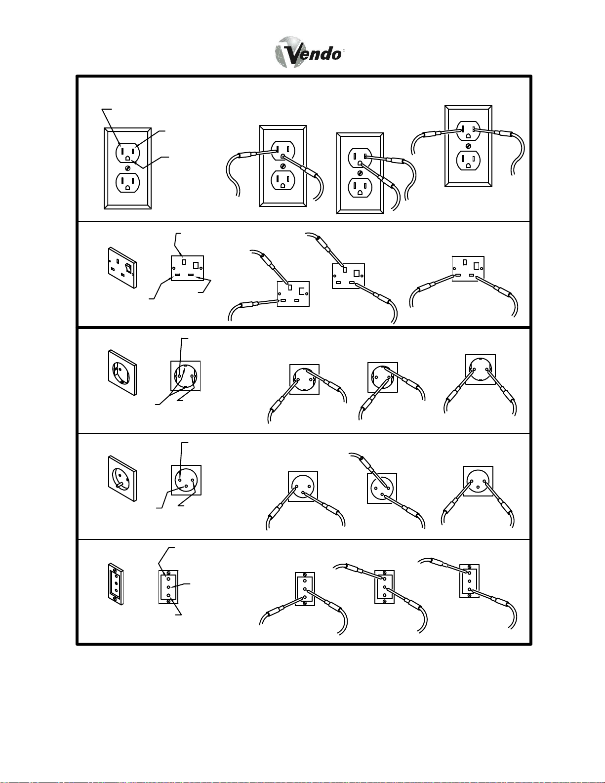
FIGURE 1
NEUTRAL (BLUE
OR LIVE (BROWN
NEUTRAL (BLUE
OR LIVE (BROWN
NEUTRAL (BLUE
OR LIVE (BROWN
EARTH CONTACT
GREEN AND YELLOW
CHECKING FOR PROPER POLARIZATION
KET
STEP 1
STEP 1
STEP 2
STEP 2
STEP 3
STEP 3
MS-4
SECTION I: VENDOR INSTALLATION (CONTINUED)
For Type 1 and Type 2 outlets, test for Grounding and Polarization as follows:
1. With a test device (volt meter or test light), connect one probe to the
receptacle’s Neutral contact and the ot her to the Live contact. The test
device should show a reaction.
2. Connect one probe to the receptacle’s Ea rth contact and the other to the Live
contact. The test device should show a reaction.
For Type 3 through Type 5 outlets, test for Grounding as follows:
1. With a test device (volt meter or test light), determine which of the
receptacle’s power contacts is the Live contact.
A. Connect one probe to the receptacle’s Earth contact.
B. Connect the second probe to the le ft (or upper), power contact. If a
reaction occurs, this is the Live power contact. If a reaction does not
occur, move the second probe to the right (or lower), contact. A
reaction should occur, indicating that this is the Live power contact.
2. Connect one probe to the receptacle’s Live power contact (as determined in
step 1). Connect the second probe to the other power contact (neutral). The
test device should show a reaction.
IF THE ABOVE CONDITIONS ARE NOT MET FOR THE
GIVEN OUTLET TYPE, CONTACT A LICENSED
ELECTRICIAN AND HAVE THE NECESSARY
CORRECTIONS MADE.
Ambient temperature operati ng range for this vendor is +5 °F to +113 °F
(-15°C to +45°C). The climatic rating of this vendor is “N” (Normal).
MS-5
SECTION I: VENDOR INSTALLATION (CONTINUED)
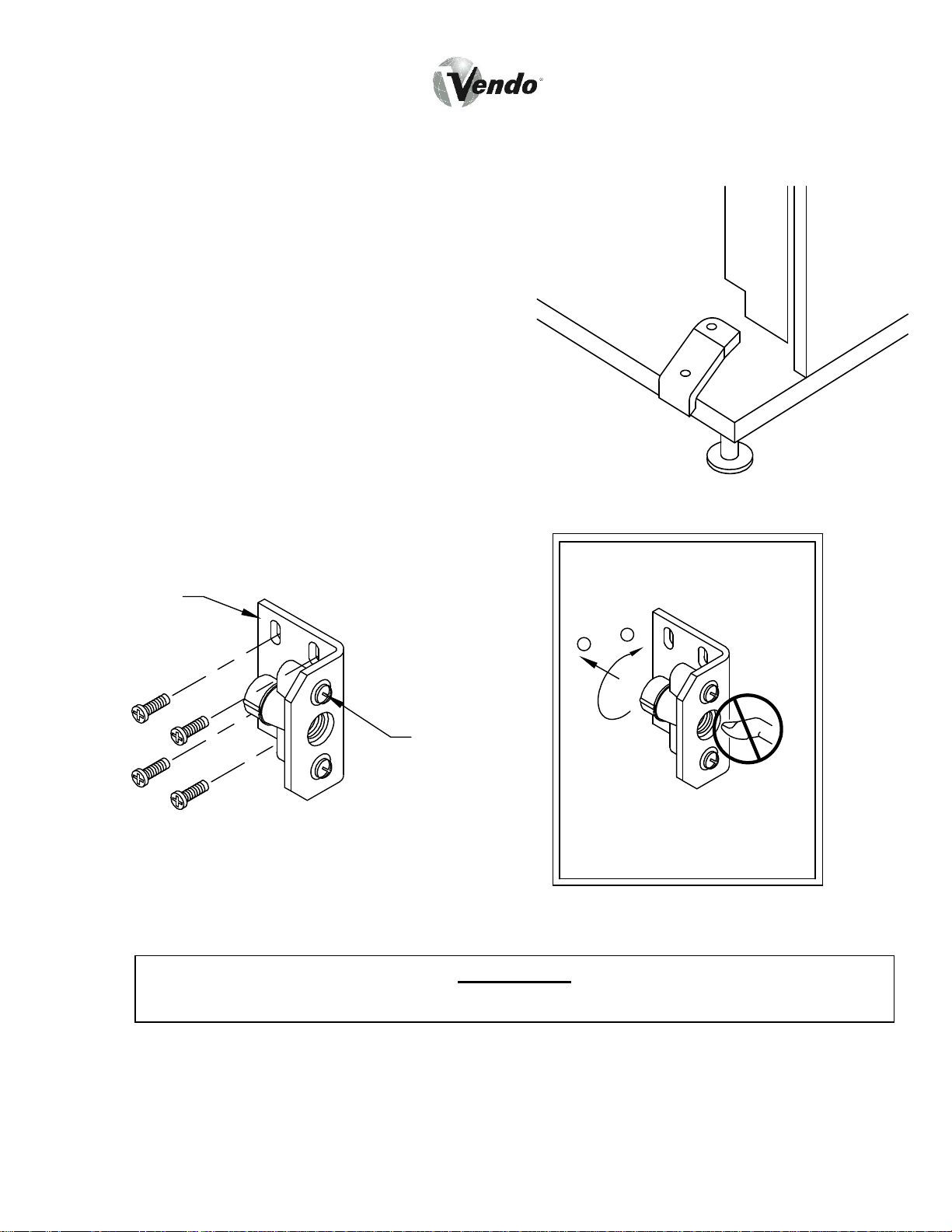
G. Door Support (Fig. 2)
The door support is to insure that the
outer door closes squarely to the
cabinet. Raising or lowering the door
support can also insure proper
alignment of the door latch.
H. Door Latch Alignment (Fig. 3)
After any door adjustment, the floating
Quicker Lock assembly should align
itself automatically. The latch
assembly is adjustable. To adjust,
loosen the latch bracket mounting screws,
and raise or lower the latch assembly into
position, then tighten the mounting
screws.
LATCH
BRACKET
FIGURE 2
DO NOT INSERT OBJECTS
INTO LOCK CAVITY.
MOUNTING
SCREW
FIGURE 3
NOTE: Refer to the appropriate Parts and Service Manual for detailed
KEEP FINGER AND OTHER OBJECTS OUT OF LOCK CAVITY.
instructions, operating principles, and recommended maintenance
intervals and procedures.
WARNING:
MS-6
TO FREE OBJECTS, REMOVE
LOCK CAP AS SHOWN
SECTION II: ELECTRICAL HAZARDS
GENERAL
Vendo vending machines are provided with t he appropriate power supply setting for
your area. All model s are equipped with transformers, enabling the vending
machine to operate on different main volt ages. Refer to page MS -4 for information
to determine the main power requirements. Refer to the appropriate Service Manual
for details of transformer operations.
The power sources are standard for both household and commercial lighting and
appliances. However, careless or improper hand ling of electrical circuits can result
in injury or death. Anyone installing, repairing, loading, opening, or otherwise
servicing a vending machine should be alerted to this point. Apply all of the normal
precautions observed in handling electrical circuits, such as:
• Refrigeration servicing to be performed by qualified personnel only.
• Unplug the vendor or move power switch to off position before servicing or
clearing product jams.
• Replace electrical cords if there is any evidence of fraying or other damage.
• Keep all protective covers and ground wires in place.
• Plug equipment into outlets that are properly polarized, where applicable, and
protected with fuses or circuit breakers.
• All electrical connections must be dr y and free of moisture before applying
power.
A. Grounding Systems
Vendo vending machines are provided wit h the appropriate service cord for
the power supply in your area. The service cord will connect to the matching
electrical outlet. Always ensure that the outlet to be used is properly
grounded, and polarized where applicable, be fore plugging in the vendor.
(See pages MS-3 - MS-5).
WARNING:
ALWAYS TEST TO VERIFY PROPER GROUNDING PRIOR TO
INSTALLATION IN ORDER TO REDUCE THE RISK OF ELECTRICAL
SHOCK AND FIRE.
The electrical grounding system also incl udes the bonding of all metal components
within the vendor. This involves a system of bonding wires ident ified by green or
green and yellow marking. The system us es serrated head screws, lock washers,
and star washers to insure the electric al connection between parts. Maintenance of
vending equipment may involve disassemb ly. Include the above items when
reassembling, even if the vending machine may appear to function normally without
them. Omitting any of these items can co mpromise a link in the grounding system.
MS-7
See the appropriate Service Manual or kit instructions for components and assembly
instructions.
SECTION II: ELECTRICAL HAZARDS (CONTINUED)
B. Servicing with “Power Off”
For maximum safety, unplug the servic e cord from the wall outlet before
opening the vendor door. This will remo ve power from the equipment and
avoid electrical and mechanical hazards . Service personnel should remain
aware of possible hazards from hot components even though electrical power
is off. See the appropriate sections of this manual for further information.
C. Servicing with “Pow er On”
Some service situations may requi re access with power on. Power-on
servicing should be performed only by fully qualified service technicians.
Particular caution is required in servic ing assemblies that combine electrical
power and mechanical movement. Sudden movement, to escape mechanical
action, can result in contact with live ci rcuits and vice versa. It is therefore
doubly important to maintain maximu m clearances from both moving parts
and live circuits when servicing.
WARNING:
“POWER-ON” SERVICING SHOULD BE ACCOMPLISHED ONLY BY
FULLY TRAINED PERSONNEL. SUCH SERVICE BY UNQUALIFIED
INDIVIDUALS CAN BE DANGEROUS.
Power to lighting system is shut off automatically by the electronic controller when
the outer door is opened.
MS-8
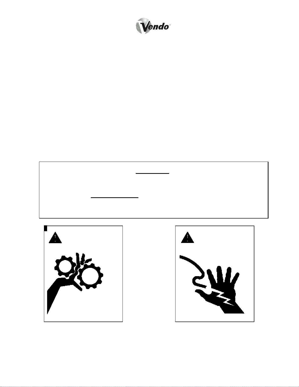
SECTION III: MECHANICAL HAZARDS
A. Servicing of Moving Parts and Assemblies
When servicing assemblies involving moving parts, use extreme caution!!
Keep fingers, hands, loose clothing, hair, t ools, or any foreign material clear
of entrapment.
As noted before under the Electrical Haza rds section, “Power On” servicing
should only be performed by qualified personne l. Refer to and heed the
warnings noted in Electrical Hazards se ction. These warnings refer to the
potential hazards associated with electric al power and moving parts. Always
maintain maximum clearances from electrical and moving parts.
Always reinstall protective covers and guards when reassembling equipment.
WARNING:
THIS VENDING MACHINE INCLUDES MECHANICAL EQUIPMENT
WHICH CAN BE HAZARDOUS IF IMPROPERLY HANDLED OR
SERVICED. USE CAUTION AND CONSULT THE VENDO SAFETY
MANUAL AND THE VENDO SERVICE MANUAL FOR ADDITIONAL
SAFETY INFORMATION.
WARNING
RISK OF ENTRAPMENT
WARNING
!
RISK OF SHOCK
ELECTRICAL
!
!
MS-9
SECTION IV: REFRIGERATION HAZARDS
GENERAL
Refrigeration systems involve both electric al power and mechanical action. These
systems may present any of the potent ial dangers shown in the sections on
Electrical and Mechanical Hazards contained in this manual.
A. Compressed Refrigerant
Refrigeration systems involve the compression and evaporation of gases.
The pressures contained represent a potent ial hazard if suddenly released in
confined areas. Caution is requir ed when performing maintenance tests or
repairs. All testing of sealed refr igeration systems should be done by trained
personnel who are familiar with the systems and pressures involved.
B. Physical Protection
The accidental release of refrigerant gas es can result in physical injuries.
Always wear protective glasses and protect your hands, face, and body when
working near the refrigeration system.
WARNING:
ALWAYS WEAR EYE PROTECTION AND PROTECT YOUR HANDS,
FACE, AND BODY WHEN WORKING NEAR THE REFRIGERATION
SYSTEM.
SECTION V: TEMPERATURE HAZARDS
GENERAL
Maintenance personnel should be alert to the potential hazards from hot metal
surfaces. High temperatures may be present throughout the refrigeration system
although electrical power has been removed.
MS-10
SECTION VI: SUBSTITUTIONS AND MODIFICATIONS
GENERAL
Unauthorized changes, or the substitution of unauthorized parts, can compromise
the equipment designs. This can result in unsafe conditions for either the service
personnel or the equipment users. Alwa ys refer to the appropriate Parts and
Service Manual for replacement parts and maintenance instructions. If questions
arise, contact the Technical Services Depar tment of the Vendo offi ce in your area.
(See pages 105 and 106.)
When servicing the vending machine, alwa ys reassemble all components to their
original location and position. Maintain t he correct routing for tubing, electrical
wiring, etc. Replace all cl amps, brackets, and guides to their original locations.
Replace all tubing, sleeving, insulating ma terial, and protective covers to their
original condition.
WARNING:
VENDO EQUIPMENT HAS BEEN PROVIDED WITH APPROPRIATE
PROTECTIVE DEVICES TO PROTECT AGAINST THE POSSIBILITY
OF OVERHEATING AND FIRE, AS A RESULT OF EQUIPMENT OR
COMPONENT FAILURES. SUBSTITUTION, MODIFICATION, OR
BYPASSING OF SUCH PROTECTIVE DEVICES CAN CREATE
DANGEROUS CONDITIONS. PROTECTIVE CIRCUITS SHOULD
NEVER BE BYPASSED, AND FAILED PROTECTIVE DEVICES MUST
BE REPLACED ONLY WITH FACTORY-AUTHORIZED PARTS.
A. Service Cord Replacement
Vendo vending machines are furnished with unique power supply cords. If
replacement becomes necessary, cons ult the Parts Section and order the
correct replacement cord for the model of vending machine in question. Do
not use substitute replacement cords. Only authorized service personnel with
appropriate training should replace the vending machine service cord. If a
question should arise concerning which se rvice cord to order, contact the
Technical Services Department of t he Vendo office in your area for
assistance.
MS-11
SECTION VI: SUBSTITUTIONS AND MODIFICATIONS (CONT’D)
WARNING:
THIS APPLIANCE MUST BE EARTHED
IMPORTANT
The wires in the mains leads are colored in accordance with the following
code:
110/120 220/240
Green Green and Yellow ............................ Earth
White Blue .................................................. Neutral
Black Brown ............................................... Live
MS-12
A
A
3
SECTION VII: CONSUMER SAFETY WARNING
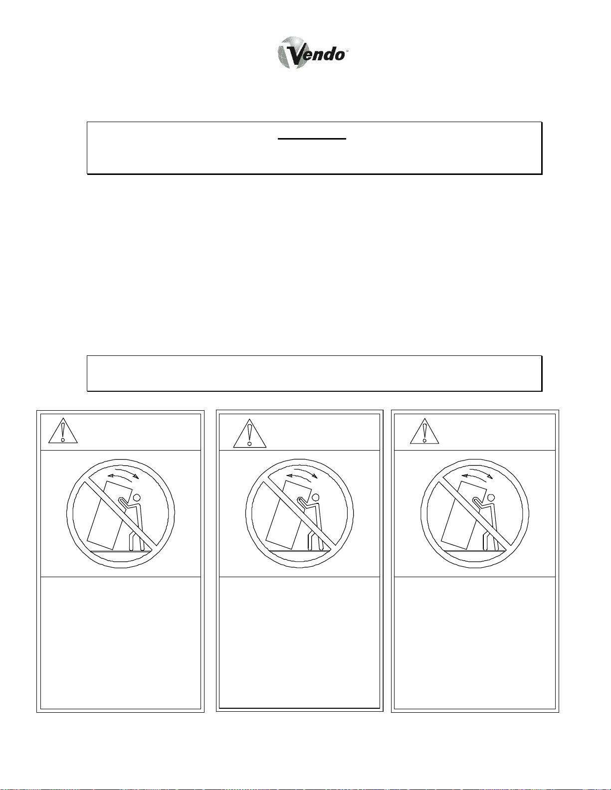
WARNING
:
VENDOR CAN BE OVERTURNED IF SUFFICIENT FORCE IS
APPLIED, AND MAY RESULT IN SERIOUS INJURY OR DEATH.
GENERAL
There have been incidents, including fatalit ies, when vending machines have been
vandalized by being pulled over in an attempt to obtain free product or money.
To warn of the danger involved in tipping, shaking, or rocking the vending machine,
a decal has been designed to be affixed to vending machines. (One such decal is
supplied with the vending machine.) Vendo will supply sufficient decals to be placed
on all machines, on request. Should you r equire additional information, contact a
service representative. See parts, sales and service centers listed on page 105 and
106.
THE FOLLOWING DECAL SHOULD BE PLACED IN A POSITION ON
THE VENDOR CONTROL PANEL AT EYE LEVEL.
MISE EN
WARNING
GARDE
AVISO
Never rock or tilt.
Machine can fall over
and cause s erious
injury or death.
Vending machine will
not dispense free
product.
89611A
ENGLISH
Ne jamais secouer
ou incliner.
Le distributeur peut
se renverser et causer
des blessures graves
ou la morte.
Cette machine ne
distribue pas de
produits gratuitement.
FRENCH
MS-13
389611-1
Nunca voltie o incline
esta maquina.
Puede caer sobre usted
y cauzarle heridas
graves o matarle.
Esta Vendomatica no
provee producto gratis.
389611-2
SPANISH

GENERAL INFORMATION
MG-1
GENERAL INFORMATION
This manual contains programming, operation, and complete parts and electrical
wiring diagrams.
The Mars controller has a microprocessor which will permit pricing per selection from
0.00 to 99.99. This machine also has space-to-sales programming.
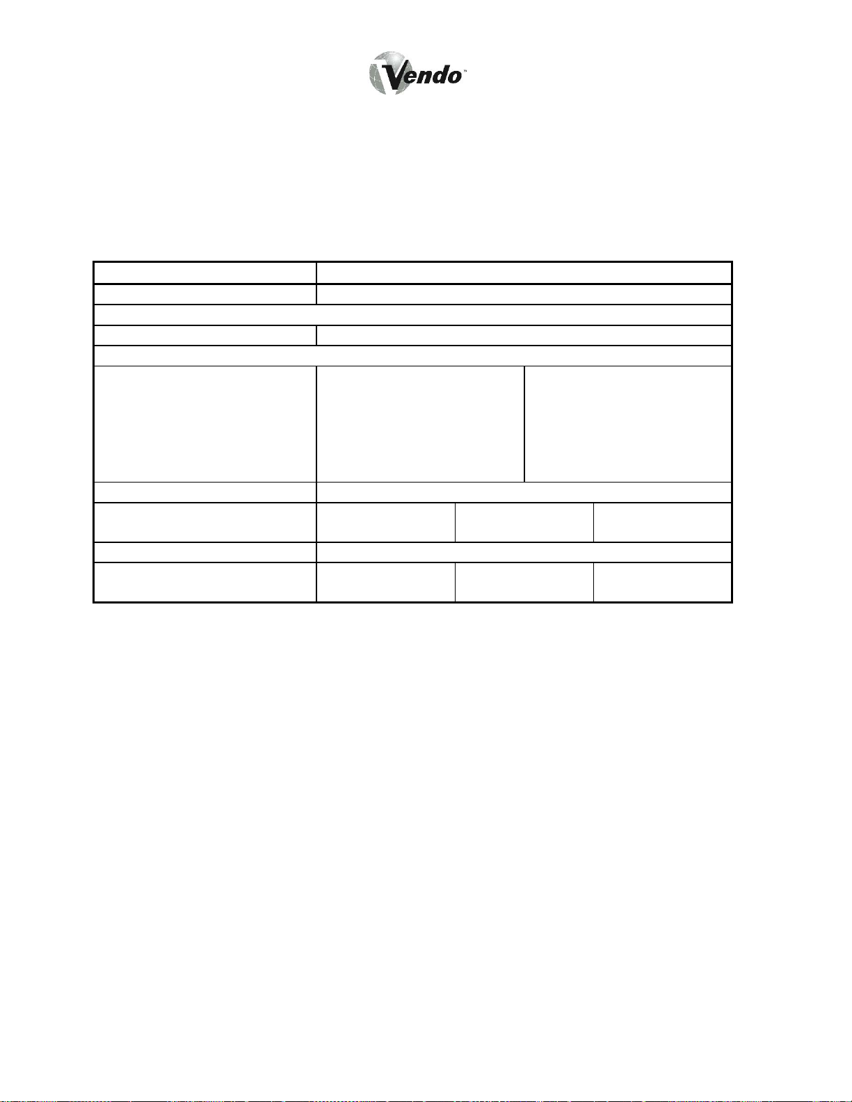
Specifications:
MODEL MARS
SELECTIONS 10
DIMENSIONS (HEIGHT X WIDTH X DEPTH)
CURVED DOOR 72” x 39“ x 30”
VENDING PRODUCT CAPACITY:
BAR MODULE:
46 BARS PER COL.
4 COL. PER MODULE
TOTAL: 184 BARS PER
MODULE
SHIPPING WEIGHT 685 POUNDS
OPERATION VOLTAGE 115v 60 Hz.
AMP. RATING 10
REFRIGERATION
VOLTAGE
*Dimensions and shipping weight will vary slightly due to manufacturing tolerances,
shipping boards, and whether or not coinage is installed.
BAG MODULE:
39 BAGS PER COL.
3 COL. PER MODULE
TOTAL: 117 BAGS PER
MODULE
220v 50 Hz
(U.S.)
115v 60Hz.
220v 50 Hz
(U.S.)
UNIVERSAL MODULE:
21 PRODUCTS PER
COL.
3 COL. PER MODULE
TOTAL: 63 PRODUCTS
PER MODULE
240v 50Hz
(Int’l)
(UK, Australia)
240v 50Hz
(Int’l)
(UK, Australia)
MG-2

INITIAL SET-UP
A. UNPACKING
Remove all plastic film, cardboard, and tape from the outsi de of the vendor.
Loosen any shipping devices used to secure interior parts during shipment.
To remove shipping boards from base, raise vendor on a well-stabilized lifting
device. Remove the leveling bolts t hat hold the boards in place and remove
the boards. Replace bolts to equal heights in the threaded holes.
Another method to remove shipping boards is to split the boards apart. Using
a pinch bar, or a heavy screwdriver and hammer, insert tool into the slots and
force the board apart.
B. POSITIONING AND LEVELING
IMPORTANT: PLACE THE VENDOR (IN DESIRED LOCATION) AT LEAST
3 TO 4 INCHES AWAY FROM ANY REAR OBSTRUCTION. This is for
proper air flow through the refrigerati on compartment. The system requires
front to rear air circulation for proper operation. Level vendor with leveling
bolts. Be sure all four leveling bolts are supporting the machine.
C. POWER SUPPLY CONNECTION
The vendor’s power requirements will vary depending upon the country it was
To insure safe operation of the v endor, the vendor’s power supply must be a
If the power requirements are not proper ly met, contact a licensed electrician
CAUTION: DO NOT USE AN EXTENSION CORD!
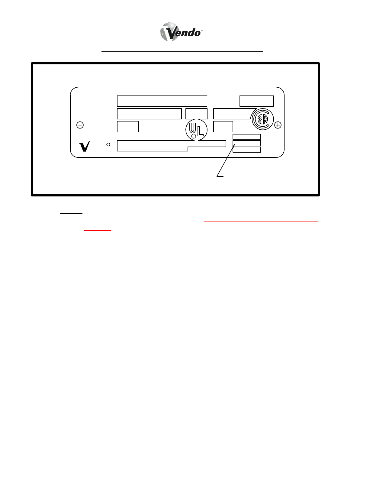
purchased for. To verify the power requirements of the vendor, check the
serial plate located on the hinge si de of the door (see Figure 4 on page MG-
6). The power requirements are listed on the serial plate.
properly grounded and polarized outlet. Be fore plugging the vendor into the
outlet, test the outlet to c onfirm it will meet the vendor ’s power requirements.
If the power supply of the outlet is different from the power requirements of
the vendor, different settings on the transformer may be necessary.
and have the necessary corrections made.
Should you require additional information, contact a service representative.
See the Parts, Sales and Service Centers listed on pages MP-34 and MP-35.
MG-3
,
0
R
A
V
INTRODUCTION AND MODEL IDENTIFICATION
Example:
APPROVED FOR OUTDOOR USE
MODEL
SERIAL NO.
Lot Code: YYMMDD
BASIC
UNIT
LR 13085
CHARGE
MIN. TEST PRESSURE APPLIED - PSI
LOW SIDE 14
OZ. R-134a
HIGH SIDE 235
endo
THE VENDO COMPANY FRESNO
CA.
239L
VENDING MACHINE
REFRIGERATED
MPS
115v
50/60
1
POWER REQUIREMENTS
OLT
CYCLE
PHASE
FIGURE 4
NOTE: The Model number of the vending machine is located on the top, left
hand corner of the serial plate. Do Not use the “BASIC UNIT”
number. The BASIC number is the cabinet size, which is used on a
number of different machines. A typical model number could read
“786502004”. 786 is the model number, and 004 tells what options are
included.
LABEL INSTALLATION
MG-4
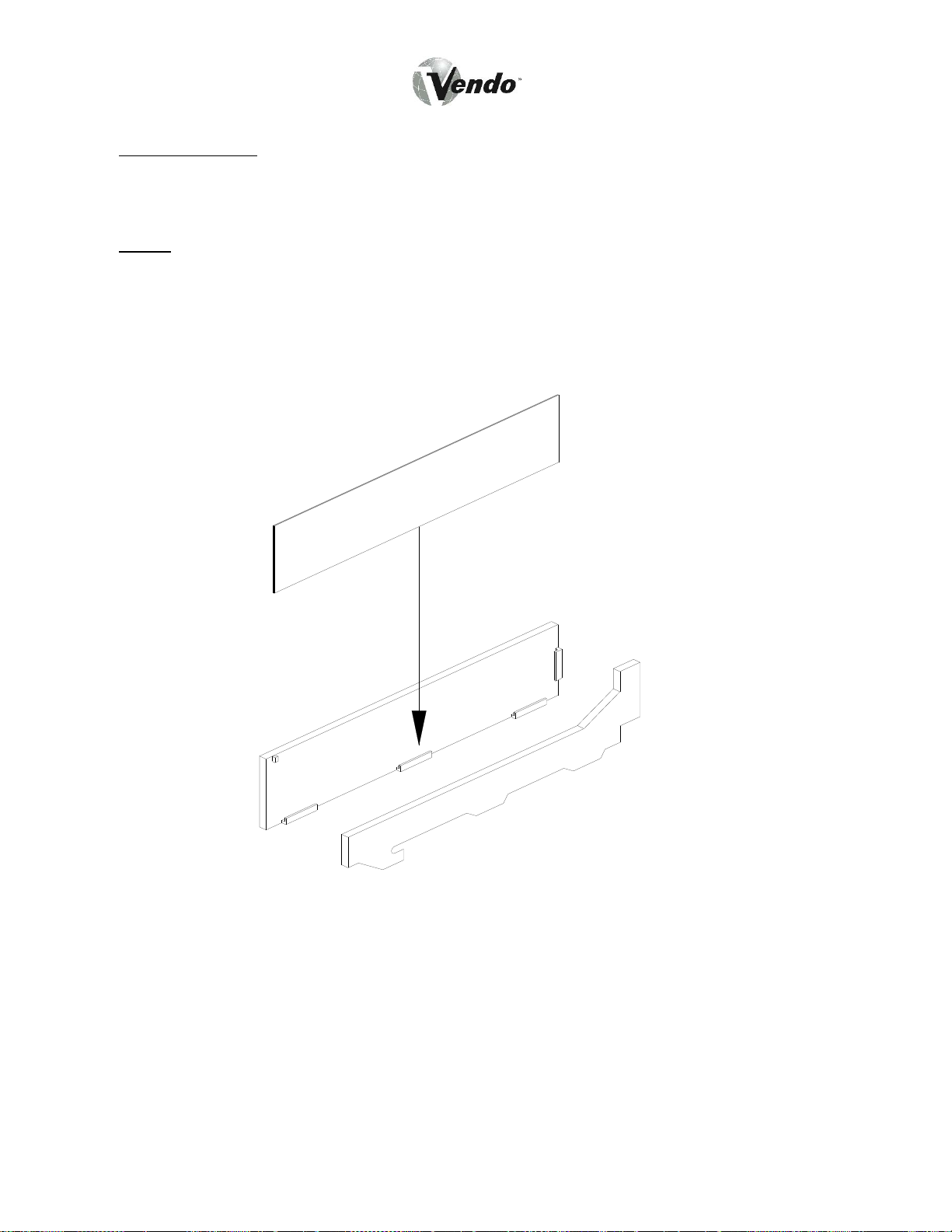
FLAVOR LABELS: Flavor labels are installed from inside the outer door. Open the vendor
door and swing the inner door away to gain access to the reverse side of the control panel.
Open the coinage door. The flavor labels slide into carrier clips on the back of each flavor
window (Figure 5).
NOTE: Make sure the correct flavor label has been installed for each selection. This vendor
can be programmed to link selection buttons to vend modules in a variety of different
configurations. Refer to the section on electronic control programming for details on the
vendor selection set-up.
Figure 5
MG-5
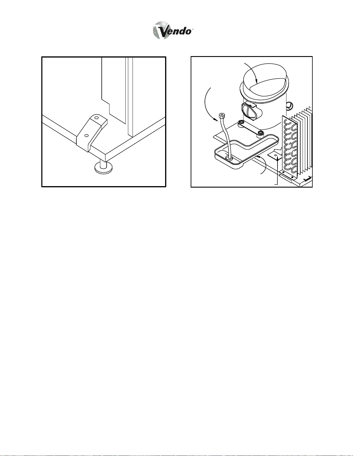
COMPRESSOR
DRAIN TUBE
PAN
FAN BRACKET
Figure 6 Figure 7
ALIGNMENT CHECKS
DOOR RAMP CHECK:
The door support is to ensure that the outer door closes squarely to the cabinet.
Raising or lowering the door will help ensure the proper alignment of the door lock
stud and the cabinet latch (see Figure 6).
REFRIGERATION AREA CHECK:
Check the position of the condensation pan (see Figure 7). The correct position of
the condensation pan is between the compressor and the condenser fan bracket.
Be sure the drain tube is clipped to the pan and free of kinks. The trap prevents
warm air from reaching the evaporator area.
VENDOR TEMPERATURE CONTROL SETTING
The cabinet temperature is regulated by the tem perature control, located on the left
side of the evaporator. Before adjusting the control, be sure the refrigeration system
MG-6
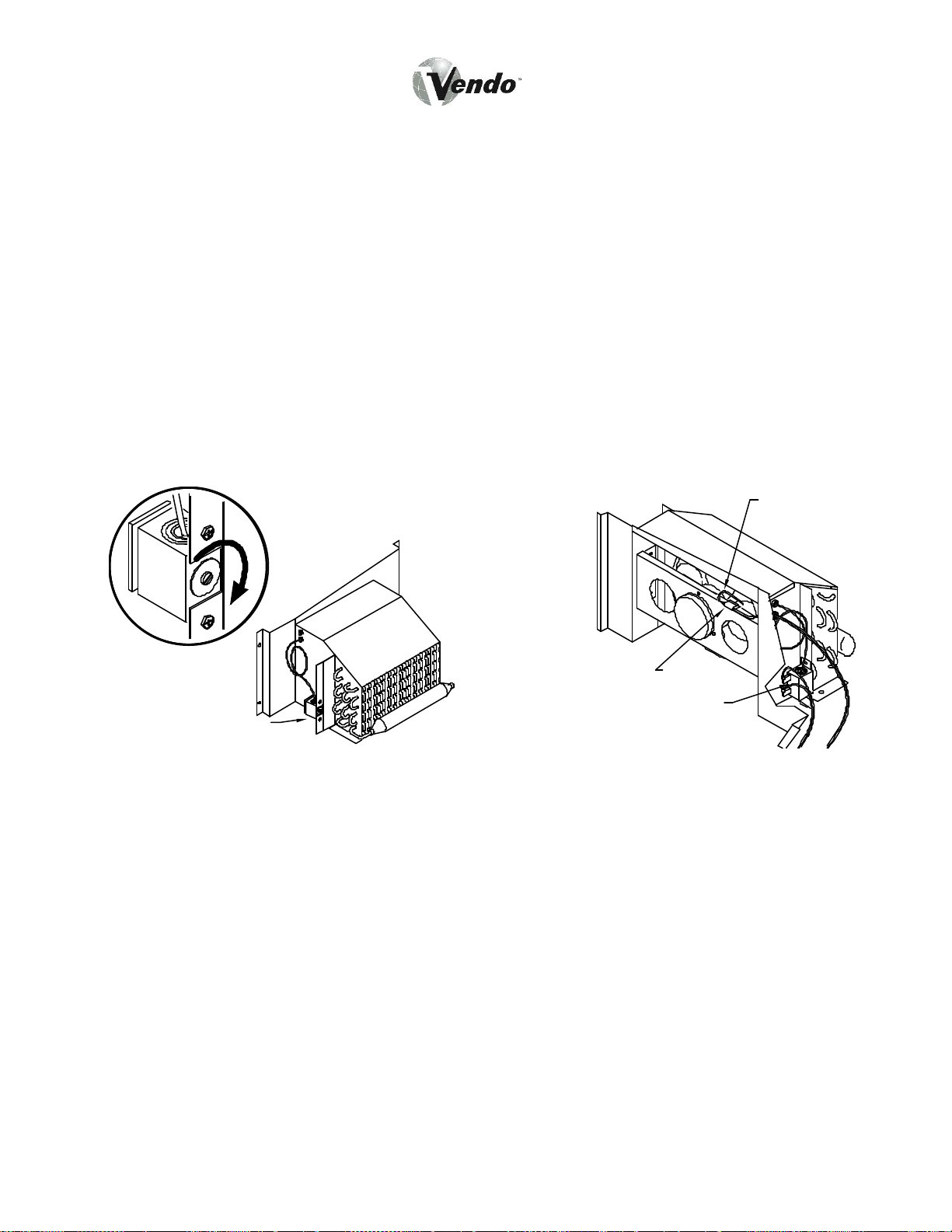
is working properly. Check that the c ondenser and evaporator fans run freely and
do not make excessive noise, which might i ndicate an obstruction to the fan blade.
The evaporator and condenser gr ills should be free from debris. In addition, check
the condition of the door gasket, to ensure a proper seal on the cabinet.
When the air temperature at the feeler bulb reaches 65 °F (18 °C), the refrigeration
system should cycle on. To lower the cabi net temperature, tu rn the temperature
control adjustment screw CLOCKWISE. To raise the cabinet temperature, turn the
adjustment screw COUNTER-C LOCKWISE. The cabinet temperature will change 6
degrees for every 1/4 turn of the adjustment screw (Figure 8).
To ensure correct temperature control operation, it is essential that the control feeler
bulb be positioned in the air flow from the evaporator, and not resting against any
metal surfaces (other than the retaining clip), which will give a misleading reading to
the control. This feeler bulb should not require adjustment unless the refrigeration
system has been removed for servicing (Figure 9).
CAPILLARY
TUBE
C
O
L
D
E
R
CLIP
TEMPERATURE
TEMPERATURE
CONTROL
CONTROL
Figure 8 Figure 9
ELECTRO-MECHANICAL FUNCTION DESCRIPTION
VEND MODULE CONFIGURATION AND OPERATION:
The Mars Vendo Confectionery vendor is s pecially designed to dispense chilled bartype and bag-type products, as specified by Mars. The vendor cabinet is divided
MG-7

into two compartments; the lower porti on is open to the ambi ent environment, and
houses the majority of the refrigeration system components. T he remainder of the
cabinet is refrigerated to preserve the vended product.
The vended product, in bar, bag, or combo form, is dispensed from vend modules
mounted in the refrigerated cabinet. There are spaces for up to five vend modules in
the cabinet. The use of five modules however, requires a full 180° swing of the outer
door. The modules will always be one of four varieties:
A) Right-Hand Bar Module
B) Left-Hand Bar Module
C) Bag Module
D) Universal Module
There are two types of bar modules becaus e of the way these modules are loaded.
Bar product is loaded into only one side of the module as it is pulled out for loading.
Therefore, a right-hand bar module is always installed in the first position at the right
side of the cabinet, so that full access to the module chambers is available. The lefthand bar modules can be situated in any of the remaining positions in the cabinet.
The bag modules, on the other hand, are loaded from both sides when pulled out for
loading. Therefore, there is only one ve rsion of the bag module. Due to the
requirement for access to both sides of the module during loadi ng, these modules
can only be installed in the three center positions.
The universal module is a right-hand modul e and therefore can only reside in the
first position at the right side of the cabinet.
Each vend module consists of a steel housing with compartments, or columns,
segregated by steel partitions. On bar m odules, there will always be four chambers,
or columns, per module. On bag modules (including universal modules), however,
due to the larger size of bag product, there are only three chambers, or columns, per
module. Each module chamber, or colu mn, has a full-height access door. Bar
modules have one door per column; bag m odules have two doors per column--one
on either side of the modul e for each column. The universal module has one steel
door over all three columns. In each case, these doors keep the product in place
within each column of the module. Each module is hung from a support channel
ELECTRO-MECHANICAL FUNCTION DESCRIPTION (CONTINUED)
mounted to the cabinet ceiling, and suspended between a pair of sliding rails, which
allows the module to be pulled forward for loading.
The product is stored and dispensed by a motor-driven plastic product helix, except in
the case of the universal module, where the helix is a powder-coated wire helix. The
bar product helix, bag product helix, and universal product helix are different part
MG-8

numbers, as both the diameter and pitch are different. The helix, in the case of the
bar and bag, is driven by the same part number vend motor. The universal helix is
driven by its own motor that is different from the bag and bar motors. The vend
motors are mounted to a steel support channel at the top of each module, and are
connected by a module harness to the cabinet harness. The vend motors are
connected to the electronic controller in such a way that any combination of vend
motors can be assigned to an individual selection button. This feature allows spaceto-sales programming of the vendor’s column to the selection buttons to maximize the
use of space for prime product versus slower-moving products.
PRODUCT LOADING:
As described, there are thr ee types of vend modules: Bar modules, Bag modules,
and Universal modules. Each has a unique loading process.
For BAR MODULES, products can only be loaded from one side of the module. The
desired module is pulled to the limit of its slides, allowing access to all columns in the
module. The door on the desired column is swung open. Product to be loaded is
slid onto the flights of the product helix, END FIRST, on either side of the helix stem.
Also, place the bar into the helix UPSIDE DOWN. For first- in-first-out sales, it is
important that the new product be put into the top of the helix, until no flights are left
open. Once full, the door on t hat column can be closed. The door is held closed by
a magnetic strip on the door edge. The rema ining bar columns in that module can
be loaded in a similar fashion. Once fi nished, the module is pushed back into the
cabinet, until the slides stop further motion.
For BAG MODULES , the process is identical to t hat for bar modules, except that
vended product is loaded SIDEWAYS on either side of the he lix, with both doors
open on that column. Also, place the bag in to the helix UPSIDE DOWN. The same
first-in-first-out rules apply to bag modules. Product should lie as flat as possible in
the helix. Avoid wadding up bags as they are set into the helix, as they could cause
vend problems.
THE VEND CYCLE:
In order to initiate a vend, the customer must first set up a credit. A credit is
registered by inserting coins into the coin slot (and into the coin mechanism), by
inserting a bill into the bill validator, (if available), or by inserting a debit card into the
debit-card reader, (if available). Once a credit is established equal to or in
ELECTRO-MECHANICAL FUNCTION DESCRIPTION (CONTINUED)
excess of the lowest product pric e, the customer is allowed to make a selection. By
pressing the selection button of their choi ce, a signal is sent to the electronic
controller, which, in turn, feeds power to the vendor column(s) assigned to that
selection.
Product is vended when a vend motor assigned to that selection is energized by a
circuit from the electronic controller. The motor rotates its product helix, and drops
MG-9

the bottom product out of the bottom of t he helix. The product falls freely onto the
product chute.
As the product passes down the product chute, it passes through the vend detection
system, where optical sensors detect the passage of the product on its way to the
product hopper. The passage of product through the vend detection sensors signals
the electronic controller, which then performs a variety of functions. The vended
product ends up in the product hopper and is removed by the customer as they push
open the vend door. (See pages MG-17 - MM3 for further electronic controller
details.)
MG-10

REFRIGERATION SYSTEM - FUNCTION DESCRIPTION
BASIC REFRIGERATION PRINCIPLES:
A refrigeration system is pr incipally involved in the process of transferring heat.
Heat is removed from the vending product area of the cabinet and transferred to the
condenser, where it is dissipated. With vending equipment, large quantities of heat
must be transferred economically and efficiently in a continuous fashion, without loss
of refrigeration gas, over a long peri od of time. The most common type of
refrigeration system in vending is the v apor compression, or simple compression,
cycle system. This system consists primarily of three elements: A compressor, an
evaporator, and a condenser, joined together as a “sealed system”.
In the vapor compression system, there are two pressures present: Low,
evaporating pressure and high, condensing pre ssure. The refrigerant gas acts as
the transport medium in which heat is transferred from the evaporator to the
condenser, where heat is dissipated into ambi ent air. A change of state occurs as
the refrigerant changes from liquid to v apor and back to liquid again, allowing the
refrigerant to absorb and discharge large quantities of heat in an efficient manner.
The basic vapor compression cycle occurs as follows: In the evaporator, the
refrigerant boils (evaporates to vapor), at a temperature su fficiently low enough to
absorb heat from the cabinet space being cooled. The boiling temperature is
controlled by the pressure maintained in the evaporator. The higher the pressure,
the higher the boiling point. The compressor removes the vapor via suction lines
from the evaporator at a rate sufficiently rapid to help maintain the desired pressure.
The compressor takes the low pressure vapor and compresses it, increasing both
the pressure and temperature of the vapor. This hot, high-pressure gas is forced out
of the compressor discharge valve and into the condenser. Upon reaching the
condenser, the refrigerant dissipates its heat and condenses into liquid. This liquid,
in turn, flows from the condenser back to the evaporator to repeat the cycle.
VENDO REFRIGERATION SYSTEM OPERATION:
The general cycle described above occurs withi n the refrigeration system fitted in
Vendo equipment. A more detailed explanation of the function of the various
components in the system follows.
As the temperature within the cabinet increases, the liquid contained in the
temperature control feeler bulb also rises in temperature and, in doing so, expands.
This expansion increases the pressure against the temperature control bellows, and
actuates the temperature control switch. This switch directs power to the
compressor and condenser fan motor. The compressor pulls low pressure
refrigerant vapor from the evaporator and compresses it, increasing both its
temperature and pressure. This high-temperature / pressure vapor is expelled to the
condenser, where the vapor sheds its excess heat, as drawn off by the air flow
created by the condenser fan through the condenser fins. More specifically, the
REFRIGERATION SYSTEM - FUNCTIONAL DESCRIPTION (CONTINUED)
MG-11

condenser fan pulls air through the condenser , removing heat from the refrigerant
vapor in the condenser coils.
The cooled gas in the condenser turns to li quid, which is pumped via pressure from
the compressor through the drier, which re moves any water and particles from the
liquid refrigerant. This liquid is then forced through the small diameter capillary tube,
which acts like a throttle for the system, controlling the flow rate of the liquid
refrigerant into the evaporator. Air flow is circulated throughout the cabinet by the
evaporator fan, which pulls air flow through the coils and fins of the evaporator. Any
excess heat present in the air flow is dr awn off by the liquid refrigerant, which
evaporates, and is, in turn, pulled via the compressor. The falling temperature in the
cabinet eventually cools the liquid in the temperature control feeler bulb, condensing
the liquid inside and reducing its pressure, wh ich releases the pressure against the
temperature control bellows. This reduction deactuates the switch inside, cutting off
power to the compressor and condenser fan motor.
HEATING SYSTEM - FUNCTION DESCRIPTION
VENDO HEATING SYSTEM OPERATION:
The MVC-600 is also equipped with a heat ing element for cold weather
environments. This system consists of a simple 150W, 230V or 115V heating
element located just behind the evaporator fan air ducting. This unit is controlled by
its own thermostat and is activated when te mperatures are in danger of freezing the
product.
CAUTION: The heating element can cause minor burns to your hands and fingers
if touched when the element has been energized for any length of time.
MG-12

VENDOR ELECTRONIC CONTROLLER
DESCRIPTION:
The Mars Vendo Confectionery machine co mes equipped with an integral electronic
control system which manages the vendor’s mechanical functions, monitors the
vend system for failures, controls the vendor ’s coin mechanism, drives the vendor’s
scrolling display, and keeps track of sales data, among other functions. The control
system consists of the following major components:
• Electronic Control PC Board
• Harnessing
• Scrolling Display
• Transformer
• Reset Switch
• Vend Detection System
• Coin Mechanism
These components work together to jointl y control the vendor’s functions. The
control system is programmed with the following capabilities:
• Space-to-Sales Programming
• Sales Data Storage
• Data Retrieval via DEX/UCS Plug or Optical Datalink
• Self-Diagnostics for the Vend Mechanism
• Multi-Pricing
• Multi-Vend
• Multi-Lingual and Personal-Message Display Programming
In order to begin programming the electronic controller, it is necessary to understand
the purpose and location of each of the major components listed above.
Electronic Control PC Board: Located on the outer door, inside a protective
housing, the electronic controller is the heart of the vendor control system. This
board contains all the microprocessors, memory microchips, and other electronic
devices needed to control the functions of the vendor. Also located on the PC board
is a small push button switch, the mode s witch, whose purpose is explained in the
electronic controller programming section that follows. This switch is accessible
through a grommeted hole in the electronic controller housing cover.
Harnessing: Connected to the electronic control PC board is a series of harnesses
that supply power to the control board, and distribute power to the various systems
within the vendor. The harnesses are all key ed in such a way t hat they cannot be
installed on the wrong set of pins, or mi sconnected on their correct PC-board pins,
(refer to the Electrical Servicing section for harness connection detail).
MG-13
 Loading...