


GGFV6 & 9 Safety & Setup Manual |
REV A – 8/2016 |
ALL Equipment |
P/N: 1239503 |
SAFETY INSTALLATION,
SETUP & INSTALLATION
SECTION
Manufactured by SandenVendo America INC. 10710 Sanden Dr.
Dallas, TX 75238-1335 (800) 344-7216
Fax: (800)541-5684 Web: www.vendoco.com
Safety & Setup Section | S-1
GGFV6 & 9 Safety & Setup Manual |
REV A – 8/2016 |
ALL Equipment |
P/N: 1239503 |
A COMMITMENT TO SAFETY
SandenVendo America, Inc. is committed to safety in every aspect of our product design. SandenVendo America, Inc. is committed to alerting every user to the possible dangers involved in improper handling or maintenance of our equipment. The servicing of any electrical or mechanical device involves potential hazards, both to those servicing the equipment and to users of the equipment. These hazards can arise because of improper maintenance techniques. The purpose of this manual is to alert everyone servicing SandenVendo America, Inc. equipment of potentially hazardous areas, and to provide basic safety guidelines for proper maintenance.
This manual contains various warnings that should be carefully read to minimize the risk of personal injury to service personnel. This manual also contains service information to insure that proper methods are followed to avoid damaging the vendor or making it unsafe. It is also important to understand these warnings are not exhaustive. SandenVendo America, Inc. could not possibly know, evaluate, or advise of all of the conceivable ways in which service might be done or predict all of the possible hazardous results. The safety precautions outlined in this manual provide the basis for an effective safety program. Use these precautions, along with the service manual, when installing or servicing the vendor.
We strongly recommend a similar commitment to safety by every servicing organization. Only properly-trained personnel should have access to the interior of the machine. This will minimize the potential hazards that are inherent in electrical and mechanical devices. SandenVendo America, Inc. has no control over the machine once it leaves its premises. It is the owner or lessor’s responsibility to maintain the vendor in a safe condition. See Section I of this manual for proper installation procedures and refer to the appropriate service manual for recommended maintenance procedures. If you have any questions, please contact the Technical Services Department of the SandenVendo America, Inc. office nearest you.
SAFETY RULES
Place and store unit inside. Outdoor use or storage voids warranty and can result in an unsafe condition
Read the Safety Manual before installation or service.
Test for proper grounding before installing to reduce the risk of electrical shock and fire.
Disconnect power cord from wall outlet before servicing.
Use only fully-trained service technicians for PowerOn servicing.
Remove any product prior to moving a vendor.
Use adequate equipment when moving a vendor.
Always wear eye protection, and protect your hands, face, and body when working near the refrigeration system.
Use only authorized replacement parts.
Be aware of inherent dangers in rocking or tipping a vending machine.
Safety & Setup Section | S-2
GGFV6 & 9 Safety & Setup Manual |
REV A – 8/2016 |
ALL Equipment |
P/N: 1239503 |
SECTION I: VENDOR SETUP & INSTALLATION
A.Vendors are large, bulky machines of significant size and weight. Improper handling can result in injury. When moving a vendor, carefully plan the route to be taken and the people and equipment required to accomplish the task safely.
B.Remove all tape, shipping sealant, and Styrofoam from the vendor. Loosen any shipping devices used to secure interior parts during shipping. Remove the wooden shipping boards attached to the vendor base by the vendor leveling screws. Make certain the leveling screws are in place and functional.
C.Position the vendor on a flat smooth surface 3 to 4 inches (7.6 cm to 10.2 cm) from a well-constructed wall.
IMPORTANT: The vendor requires 3 inches (7.6 cm) of air space from the wall to ensure proper air circulation to cool the refrigeration unit.
D.Adjust the leveling screws to compensate for any irregularities on the floor surface. Ideally, no adjustment will be necessary and the leveling legs will be flush with the bottom of the vendor. A spirit level is a useful aid to level the vendor. When the outer door is open, it will remain stationary if the vendor is properly leveled. Vendors must be level to ensure proper operation and to maintain stability characteristics. Do not add legs to the vendor. The leveling legs shall not raise the vendor more than 1 1/8 inch (2.5 cm) above the ground.
E.Check the manufacturer’s nameplate on the left or right side of the vendor’s outer door to verify the main power supply requirements of the vendor. Be sure the main power supply matches the requirements of the vendor. To ensure safe operation, plug the vendor only into a properly grounded outlet.
DO NOT USE EXTENSION CORDS. DO NOT USE PLUG ADAPTORS.
F.Recommended voltage specs = 115V ± 10%
G.Dedicated 15A service required for 1 machine.
H.Power outlet must be properly polarized and grounded.
NOTE: Any power supply variance more than ± 10% may cause the vendor to malfunction.
Safety & Setup Section | S-3

GGFV6 & 9 Safety & Setup Manual |
REV A – 8/2016 |
ALL Equipment |
P/N: 1239503 |
SECTION I: VENDOR SETUP & INSTALLATION (CONTINUED)
IF THE ABOVE CONDITIONS ARE NOT MET FOR THE GIVEN OUTLET TYPE, CONTACT A LICENSED ELECTRICIAN AND HAVE THE NECESSARY CORRECTIONS MADE.
NOTE: Refer to the appropriate parts and service manual available online @ www.vendoco.com for detailed instructions, operating principles, and recommended maintenance intervals and procedures.
Safety & Setup Section | S-4

GGFV6 & 9 Safety & Setup Manual |
REV A – 8/2016 |
ALL Equipment |
P/N: 1239503 |
SECTION I: VENDOR SETUP & INSTALLATION (CONTINUED)
Set up Procedure
Note: Do not plug in the vendor until Step 5
1Unwrap the machine
2Remove all the tie wraps and packaging material
3Level machine as needed See leveling instructions
4Confirm the trays fully seated in the base
5Power on the machine
Display will read Memory operation, Data Transfer in Process
This is the process of communication between the Vending Machine Controller(VMC) and Delivery Mechanism Controller (DMC)
6Close the door –The machine will start initialization. The catcher will perform a product drop movement
The product catcher will move up and scan for each shelf location then move towards the right side
of the machine and then will move to the left side at position (bottom hinge side)
CAUTION:
Do not open the door while the elevator is in motion as this would cause the elevator to free fall
8The display should read "Ice cold Beverages!! Please Make a Selection”
9Open the door – load the machine
10* Set the machine to free vend
11 Test vend to check the vendor is working properly 12* Set Price for all selection
*Refer to Programming Manual
Loading Instructions
Please note: To ensure freshness of the product do not load from the front of the vendor. GGFV has FIFO product loading capability
1Lift and pull the front of the tray assembly.
2Push and lock the product pushers to the back of the tray.
3Load the products into the tray.
4Once the products are loaded push the tray back in its position – The product pushers will automatically snap back behind the last product For proper vending – Please make sure the products are not leaning forward or sitting up on tray front. Do not activate the product pusher when the columns are empty (damage will occur)
5Check the tray is fully seated on the front support bar.
6To ensure the product pusher is engaged Gently push the front product inward to check for resistance
7Check to confirm all products are resting on tray bottom ( behind the tray product retaining hooks)
Loading selection # 50, 51 , 52 :
Push and hold the product delivery port flap open until the product catcher moves towards the right side of the vendor to clear the loading zone for 50, 51 and 52.
Load the shelves as indicated by Step 1 – 7 Close the door.
The catcher will move to home position
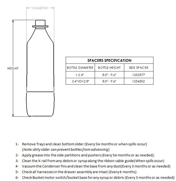
Products Specification – General Guidelines
Products* (PET, glass bottles, cans):
Height range: 3 in – 9.6 in ( 76mm 244mm ) Diameter range: 1.7 in – 3 in ( 43mm 76mm ) Weight range: 6.5oz – 23oz ( 185g 653g )
Carton packs* (Aseptic package):
Height range: 3.3 in – 5.3 in ( 85mm 134mm ) Width range: 2 in – 2.6 in ( 52mm 67mm ) Depth range: 1.6 in – 1.8 in ( 40mm 47mm ) Weight range: 7.5oz – 14oz ( 213g 400g )
*Note: Due to variability of package design, material & weight, performance may vary. Testing of odd shaped, size products should be done to determine acceptability. Continued.
Safety & Setup Section | S-5
GGFV6 & 9 Safety & Setup Manual |
REV A – 8/2016 |
ALL Equipment |
P/N: 1239503 |
*For tall/unstable bottles, we recommend using side spacers to keep bottles from leaning sideways (Please see below)
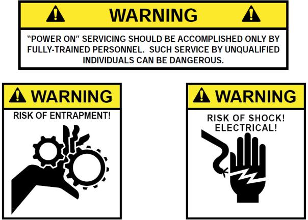
SECTION II: MAINTENANCE REQUIREMENT
Safety & Setup Section | S-6

GGFV6 & 9 Safety & Setup Manual |
REV A – 8/2016 |
ALL Equipment |
P/N: 1239503 |
SECTION III: ELECTRICAL HAZARDS
GENERAL
SandenVendo America, Inc. vending machines are provided with the appropriate power supply setting for your area.
The power sources mentioned are standard for both household and commercial lighting and appliances. However, careless or improper handling of electrical circuits can result in injury or death. Anyone installing, repairing, loading, opening, or otherwise servicing a vending machine should be alerted to this point. Apply all of the normal precautions observed in handling electrical circuits, such as:
Unplug the vendor before servicing or clearing product jams.
Replace electrical cords if there is any evidence of fraying or other damage.
Keep all protective covers and ground wires in place.
Plug equipment into outlets that are properly grounded and polarized, and protected with fuses or circuit breakers.
All electrical connections must be dry and free of moisture before applying power.
Replace Fuses with same type.
Refrigeration servicing to be performed by qualified personnel only.
A.Grounding Systems
SandenVendo America, Inc. vending machines are provided with the appropriate service cord for the power supply in your area. The service cord will connect to the matching electrical outlet. Always ensure that the outlet to be used is properly grounded before plugging in the vendor.
The electrical grounding system also includes the bonding of all metal components within the vendor. This involves a system of bonding wires identified by green or green and yellow marking. The system uses serrated head screws, lock washers, and star washers to ensure the electrical connection between parts. Maintenance of vending equipment may involve disassembly. Include the above items when reassembling, even if the vending machine may appear to function normally without them. Omitting any of these items can compromise a link in the grounding system.
Safety & Setup Section | S-7
GGFV6 & 9 Safety & Setup Manual |
REV A – 8/2016 |
ALL Equipment |
P/N: 1239503 |
SECTION III: ELECTRICAL HAZARDS (CONTINUED)
B.Servicing with “Power Off”
For maximum safety, unplug the service cord from the wall outlet before opening the vendor door. This will remove power from the equipment and avoid electrical and mechanical hazards. Service personnel should remain aware of possible hazards from hot components even though electrical power is off.
C.Servicing with “Power On”
Some service situations may require access with the power on. Power on servicing should be performed only by fully-qualified service technicians. Particular caution is required in servicing assemblies that combine electrical power and mechanical movement. Sudden movement (to escape mechanical action) can result in contact with live circuits and vice versa. It is therefore doubly important to maintain maximum clearances from both moving parts and live circuits when servicing.
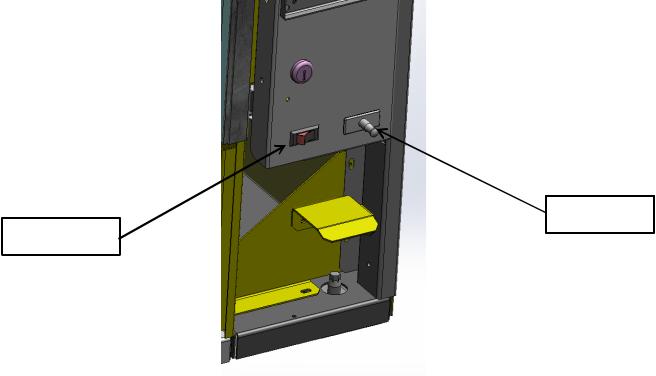
Power to lighting and refrigeration system is shut off automatically by the electronic controller when the outer door is opened. However, it is strongly recommended that servicing the lighting system or the refrigeration system only be performed after unplugging the vendor power cord, or by turning the power switch off (See Figure 1).
Safety & Setup Section | S-8
GGFV6 & 9 Safety & Setup Manual |
REV A – 8/2016 |
ALL Equipment |
P/N: 1239503 |
NOTE: For power-on servicing of the vendor’s lighting system, turn lighting power on by accessing the Lights test function of the electronic controller, or by pulling the door switch forward to the override position.
Caution:
After the door switch is pulled forward or door closed, the elevator will move automatically as part of the homing routine.
Always make sure the path of the elevator and the rail is clear before closing the door or pulling the door switch forward.
Caution: Do not open the door while the elevator is moving.
For power-on servicing of the vendor’s refrigeration system, turn refrigeration power on by accessing the Compressor test function of the electronic controller, or by pulling the door switch forward to the override position. Note that there will be a delay of 3 minutes before the compressor is energized.
DOOR SWITCH
POWER SWITCH
FIGURE 1
Safety & Setup Section | S-9
GGFV6 & 9 Safety & Setup Manual |
REV A – 8/2016 |
ALL Equipment |
P/N: 1239503 |
SECTION IV: MECHANICAL HAZARDS
A.Servicing of Moving Parts and Assemblies
When servicing assemblies involving moving parts, use extreme caution!! Keep fingers, hands, loose clothing, hair, tools, or any foreign material clear of entrapment.
As noted before under the electrical hazards section, Power On servicing should only be performed by qualified personnel. Refer to and heed the warnings noted in the electrical hazards section. These warnings refer to the potential hazards associated with electrical power and moving parts. Always maintain maximum clearances from electrical and moving parts.
Always install protective covers and guards when reassembling equipment.
Safety & Setup Section | S-10
GGFV6 & 9 Safety & Setup Manual |
REV A – 8/2016 |
ALL Equipment |
P/N: 1239503 |
SECTION V: REFRIGERATION HAZARDS
GENERAL
Refrigeration systems involve both electrical power and mechanical action. These systems may present any of the potential dangers shown in the sections on electrical and mechanical hazards contained in this manual. See Sections II and III for further information.
A.Compressed Refrigerant
Refrigeration systems involve the compression and evaporation of gases. The pressures contained represent a potential hazard if suddenly released in confined areas. Caution is required when performing maintenance tests or repairs. All testing of sealed refrigeration systems must be done by trained personnel who are familiar with the systems and pressures involved.
B.Physical Protection
The accidental release of refrigerant gases can result in physical injuries. Always wear protective glasses and protect your hands, face, and body when working near the refrigeration system.
R290 REFRIGERANT (PROPANE)
For units that use R290 refrigerant, please use additional caution as described below.
Global warming gas
Ozone Hole
R290
|
|
(Propane) |
Not destroy Ozone layer |
Low potential of Grobal |
Very Flammable |
|
warming |
|
Safety & Setup Section | S-11
GGFV6 & 9 Safety & Setup Manual |
REV A – 8/2016 |
ALL Equipment |
P/N: 1239503 |
Refrigerant |
R290 (Propane) |
|
|
Ozone Destructive Potential |
0 |
|
|
Global Warming Potential |
3 |
|
|
Permission Concentration |
1,000 ppm |
|
|
Operating pressure |
180 psig (1.2 MPa) |
|
|
DANGER:
Risk of fire or explosion. Flammable refrigerant used. Use extreme caution when handling, moving unit as to not increase risk of damage to refrigerant tubing or increasing the risk of a leak.
Caution:
The refrigeration unit contains R290 (Propane). Only a service technician that has been trained with the operation of R290 (Propane) should service the refrigeration system, so as to minimize the risk of possible ignition due to incorrect parts or improper service. Components parts shall be replaced with like components.
Notice:
Vending machines using R290 (Propane) refrigerant shall not be intended for use in lobbies or locations of egress, such as a hallway or public corridor.
SECTION VI: TEMPERATURE HAZARDS
GENERAL
Maintenance personnel should be alerted to the potential hazards from hot metal surfaces. High temperatures may be present throughout the refrigeration system even though electrical power has been removed.
Safety & Setup Section | S-12
GGFV6 & 9 Safety & Setup Manual |
REV A – 8/2016 |
ALL Equipment |
P/N: 1239503 |
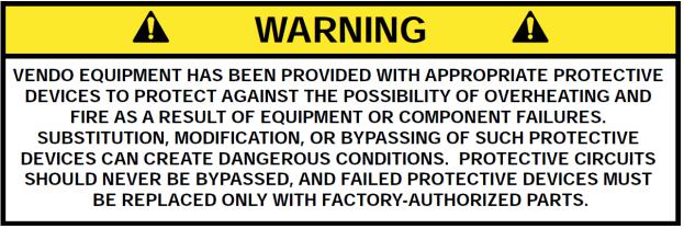
SECTION VII: SUBSTITUTIONS AND MODIFICATIONS
GENERAL
Unauthorized changes or the substitution of unauthorized parts can compromise the equipment designs. This can result in unsafe conditions for either the service personnel or the equipment users. Always refer to the appropriate parts and service manual for replacement parts and maintenance instructions. If questions arise, contact the Technical Services Department of the SandenVendo America, Inc. office in your area.
When servicing the vending machine, always reassemble all components to their original location and position. Maintain the correct routing for tubing, electrical wiring, etc. Replace all clamps, brackets, and guides to their original locations. Replace all tubing, sleeving, insulating material, and protective covers to their original condition.
A.Service Cord Replacement
SandenVendo America, Inc. vending machines are furnished with unique power supply cords. If replacement becomes necessary, consult the appropriate parts and service manual and order the correct replacement cord for the model of vending machine in question. Do not use substitute replacement cords. Only authorized service personnel with appropriate training should replace the vending machine service cord. If a question should arise concerning which service cord to order, contact the Technical Services Department of the SandenVendo America, Inc. office in your area.
Safety & Setup Section | S-13

GGFV6 & 9 Safety & Setup Manual |
REV A – 8/2016 |
ALL Equipment |
P/N: 1239503 |
SECTION VIII: CONSUMER SAFETY WARNING
GENERAL
There have been incidents, including fatalities, when vending machines have been vandalized by being pulled over in an attempt to obtain free product or money.
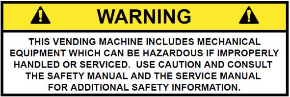
To warn of the danger involved in tipping, shaking, or rocking the vending machine, a decal has been designed to be affixed to vending machines. (One such decal is applied on the vending machine.) SandenVendo America, Inc. will supply sufficient decals to be placed on all machines, on request. If you have any questions, contact the Technical Services Department of the SandenVendo America, Inc. office in your area.
THE FOLLOWING DECAL SHOULD BE PLACED IN A POSITION ON THE
VENDOR CONTROL PANEL AT EYE LEVEL
ENGLISH |
FRENCH |
SPANISH |
Safety & Setup Section | S-14

GGFV Parts & Service Manual |
REV A – 10/2013 |
ALL Equipment |
P/N: 1231294 |
VEC 16
PROGRAMMING SECTION
GGFV Programming Section | P-1

GGFV Parts & Service Manual |
REV A – 10/2013 |
ALL Equipment |
P/N: 1231294 |
VEC 16 PROGRAMMING OPERATION
KEYWORDS:
VMC - VENDING MACHINE CONTROLLER DMC- DELIVERY MECHANISM CONTROLLER
The VEC 16 Controller uses a 4-button programming system: Programming Buttons: # 1 – Exit/ Home
#2 – Increase/ Advance
#3 – Decrease/ Backup
#4 – Enter/ Save
|
|
|
|
|
|
|
|
A: VMC LABEL |
|
|
|
|
B: EPROM / FIRMWARE |
|
|
|
|
SW1: MODE SWITCH |
|
|
|
|
J1: DEX PORT |
|
|
|
|
J2: DISPLAY |
|
|
|
|
J3: SELECTION SWITCH INPUT |
|
|
|
|
J4: RTV/SO OUTPUT |
|
|
|
|
J5: 24V POWER |
|
|
|
|
J6: BUCKET MTR, COIN |
|
|
|
|
RETURN MTR & HOPPER LED |
|
|
|
|
J7: ENERGY MANAGEMENT |
|
|
|
|
J8: OVERRIDE / AUX. DEX PORT |
|
|
|
|
J9: MDB PORT |
|
|
|
|
J10: LOCK SYSTEM |
|
|
VMC BOARD: PART # 1227995 XX |
|
|
|
|
|
J11: COIN CHUTE SENSOR |
|
|
|
|
|
|
|
|
|
|
|
|
|
|
|
|
|
GGFV Programming Section | P-2

GGFV Parts & Service Manual |
REV A – 10/2013 |
ALL Equipment |
P/N: 1231294 |
IMPORTANT INFORMATION:
General Process Description:
Ready to Vend Position: The catcher is at the bottom corner towards the hinge side of the machine – the fork on the catcher is pointing towards the trays.
Initialization Process: This process is activated during power up and Door Close scenario. The catcher will rotate 90 Degrees clockwise, to confirm Z movement.
The catcher will move sideways about 3 inches away from the hinge side and will move back to the original position – to confirm X- location.
The catcher will move up about 4 inches and back to the base – to confirm the Y-location.
The catcher will perform a vend drop movement – to confirm that there is no product in the catcher.
The catcher will move up along the hinge side of the machine then towards the right and diagonally back to the original position – to confirm the shelf locations.
The catcher will rotate 90 degrees anti-clockwise to return to the Ready to Vend Position.
Recovery Process: This process is activated anytime there is a physical obstruction during the catcher or elevator movement. The vendor will initiate the initialization process on any motor jam. The vendor retries 5 times before terminating the recovery process. If the vendor fails to recover during its 5 retries, the machine is out of order.
GGFV Programming Section | P-3

GGFV Parts & Service Manual |
REV A – 10/2013 |
ALL Equipment |
P/N: 1231294 |
To access Mode functions, open the door. Locate the Mode Button (SW1) on the Main Control Board and press until “Diagnostics” appears. Use selection button 2 or 3 to navigate through the modes.
The Modes are as follows:
Diagnostics
Coin Payout
Tube Fill
Test Mode
Cash Data
Sales Data
Discount Counter*
Free Counter*
Set Price
Shelf Location
Configuration
Door Closed Password
Set Language
Set Clock **
Lighting **
Refrigeration ***
Sales Block 1-8 **
Discount **
Override ****
Custom Message
Return
*For the Discount Counter and/ or Free Vend Counter to work, the option must be turned on and Set Clock Function must be activated and set. An override switch is required to activate the counters.
**These modes will only appear when the Timing Features in Configuration is turned On.
***Limited options appear in this mode depending on whether the Timing Features in Configuration is On/Off.
****A secondary ‘kit’ is required for this option.
Note: Items that are in quotes, for example: “X Motor”, are what is displayed on the 20 character display:
GGFV Programming Section | P-4

GGFV Parts & Service Manual |
REV A – 10/2013 |
ALL Equipment |
P/N: 1231294 |
Diagnostics:
Press Button 4 to enter Diagnostics Mode. If no errors have occurred, the display will read “Error None”. If an error code displays, enter the code using Button 4. Press Button 2 to advance through the ‘detailed summary’ of the individual error codes. To clear the errors, press and hold Button 4. The display will read “Error None”. To exit the Diagnostics Mode, press Button 1.
Coin Payout:
Coin Payout Mode allows the operator to test for proper operation of the coin changer.
1.Enter on Button 4.
2.Advance on Button 2 to choose denomination.
3.Enter on Button 4 to dispense denomination displayed.
4.Exit on Button 1.
Tube Fill:
The changer coin tubes can be filled via the external coin insert plate or the acceptor part of the changer. This mode enables the Control Board to keep an accurate count of the coins.
1.Enter on Button 4.
2.Insert coins through either the coin insert slot or acceptor part of the changer. The controller will display the value and quantity of coins in the changer tubes.
Test Mode:
Test Mode Vending:
Up to five products can be vended in this mode.
1.Press Button 4 – Display will read “Close Door to Vend”.
2.Close outer door.
3.The elevator will perform its initialization routine.
4.Display will read ”Please make a selection”.
5.Product should dispense.
Test Mode Automated Check:
This mode is automated test mode and is designed to check all the operation in vending mode. This checks the Display, Keypad, Relays, Hopper Bucket operation, coin return operation and payment system.
1.Press Button 4.
a.This will automatically sequence through to check the display, keypad, relays, hopper operation, coin return operation and payment system.
Each check operation is allocated 15 seconds.
GGFV Programming Section | P-5

GGFV Parts & Service Manual |
REV A – 10/2013 |
ALL Equipment |
P/N: 1231294 |
Test Mode Test Hopper Operation
1.Enter on Button 4 – “Testing in Progress” followed by ‘Hopper Bucket open/ Hopper Bucket close’ will display while performing these actions.
2.Confirm to make sure the display reads” Bucket Test Successful”
3.Exit on Button 1.
Test Mode Sensor Status:
1.Enter on Button 4 - Sensor Status display as follow: ESCR |BCKT |FLP:
M●|S o |M●|B● |S●
The above status shows the vendor is in a “ready to vend” mode – otherwise check the respective sensor/ switch.
ESCR M : Escrow Motor Switch ESCR S : Escrow Switch
BCKT M: Bucket Motor Switch BCKT B: Bucket Base Switch FLP S: Delivery Port Flap Switch
● : Switch is activated o : Switch is deactivated
Test Mode |
Display: |
1.Enter on Button 4
2.20”‘^” on each line should illuminate or all pixels should be illuminated.
3.Exit on Button 1
Test Mode |
Switches: |
1.Enter on Button 4
2.Activation of individual selection buttons (1 – 10, * and # ) should display
3.To Exit, press and hold Button 1 for 5 seconds or until Display returns to ‘Test Mode Switches’
Test Mode Relays:
This Mode allows you to test the following relays:
1.Compressor
2.Fluorescent Light
3.Heater
4.Fan
1.Enter on Button 1 – Compressor ‘Off’
2.Enter again on Button 4 – ‘Off’ flashes
3.Advance on Button 2 – ‘On’ flashes
4.Enter on Button 4 – Compressor should turn ‘on’ if relay is functional
5.Exit on Button 1 – Compressor will default back to ‘Off’
Repeat steps 1 through 5 for desired relay. To exit ‘Test Mode’ and return to the Main Menu, press Button 1 three times.
GGFV Programming Section | P-6
GGFV Parts & Service Manual |
REV A – 10/2013 |
ALL Equipment |
P/N: 1231294 |
Cash Data:
This Mode allows you to retrieve the total Historical Cash from product purchases.
1.Enter on Button 4 – the non-re-settable, Historical Cash Total will scroll
2.Advance on Button 2 to scroll through the shelves
3.Enter on Button 4 to show the columns in the shelves
4.Press Button 1 to exit.
Sales Data:
This Mode allows you to retrieve the total Historical Sales from product purchases.
1.Enter on Button 4 – the non-re-settable, Historical Sales Total will scroll
2.Advance on Button 2 to scroll through the selections
3.Enter on Button 4 to show the columns in the shelves
4.Press Button 1 to exit.
Discount Counter:
This Mode will only display when ‘Discounts’ are used. It allows access to the Sales and Cash Data for discounted vends.
1.Enter on Button 4 – ‘Cash Data’
2.Enter again on Button 4 – Display will read ‘Cash Data Total’ and display the value of all discounts towards paid sales. This total is non-re-settable and begins when the ‘Discount’ feature is enabled.
3.Advance on Button 2 to scroll through the various selections
4.Press Button 1 to exit
5.Advance on Button 2 – ‘Sales Data’
6.Enter on Button 4 – ‘Sales Data Total’ will display as well as the number of discounted sales. This total is non-re-settable and begins when the ‘Discount’ feature is enabled
7.Advance on Button 2 to scroll through the various selections
8.Press Button 1 to exit.
Free Counter:
This Mode will only display when ‘Free Vends’ were made. It allows the user access to the number of ‘Free Sales and Cash Data’ lost.
1.Enter on Button 4 – Cash Data total XX.XX, which is the value of the money lost based on the set price. This total is non-re-settable and begins when the ‘Free Vend Override’ is enabled.
2.Advance on Button 2 – ‘Sales Data Total X’, which is the total number of products dispensed. This total is non-re-settable and begins when the ‘Free Vend Override’ is enabled.
3.Press Button 1 to exit.
Clearing the Cash Data, Sales Data, Discount Counter or Free Counter:
To reset the individual selection counter, scroll to the selection number, press and hold buttons
# 1 and 4 for 3 seconds, 0000 will display. You can also set ‘MIS Auto Reset‘ to ‘On’ under ‘Configuration’
GGFV Programming Section | P-7

GGFV Parts & Service Manual |
REV A – 10/2013 |
ALL Equipment |
P/N: 1231294 |
Shelf Position:
This Mode shows the shelf location for individual shelf in the machine. The distance of each shelf is based off the lowest shelf. The values are displayed in “inches”
Enter on Button 4
1.Advance on Button 2 – ‘Shelf X Y inches’ X : Shelf number , Y is the total distance from the bottom shelf
2.Press Button 1 to exit.
Factory Default 5 Shelf Setting:
Shelf 1: 42”, Shelf 2: 32”, Shelf 3: 21”,Shelf 4: 10” ,Shelf 5: 0”
Please note: Shelf height will change if shelves are added or removed.
Set Price:
This Mode allows you the option to price each selection to the same vend price, or price each shelf, tray or column.
To set all selections to a ‘single price’:
1.Enter on Button 4 – All Selections .XX will display (current vend price)
2.Enter again on Button 4 – .XX (current vend price) will flash
3.Advance on Button 2 to increase the price
4.Press Button 3 to decrease the price
5.Press Button 4 to save change
6.Press Button 1 to exit.
To set price per shelf:
1.Enter on Button 4 – Set Price - Shelf 1
2.Enter on Button 4 again – Shelf 1 - All Columns displays
3.Enter on Button 4 – Shelf 1 – All columns XX flashes
4.Advance on Button 2/ decrease on Button 3 to desired price
5.Press Button 4 to save change – Shelf 1 – All columns XX
6.Press Button 1 – Set Price – Shelf 1
7.Advance on Button 2 – Set Price – Shelf 2
8.Set prices following steps outlined above for the balance of shelves
9.Exit on Button 1 twice to return to Set Price
To set price per column:
1.Enter on Button 4 – Shelf 1 – All Columns
2.Advance on Button 2 to begin pricing individual columns
3.Enter on Button 4 – Column 0 and current price flashes
4.Advance on Button 2/ decrease on Button 3 to desired price
5.Press Button 4 to save change
GGFV Programming Section | P-8

GGFV Parts & Service Manual |
REV A – 10/2013 |
ALL Equipment |
P/N: 1231294 |
Set Price (Continued)
6.Continue as outlined above for all columns on Shelf 1
7.Press Button 1 to exit once all columns on Shelf 1 have been priced.
8.Advance on Button 2 – Shelf 2
9.Price columns as indicated above for Shelves 2 through 7
10.Exit on Button 1 twice to return to Set Price
Configuration:
To change individual options for Configuration Settings, enter the option on Button 4. Re-enter on Button 4, ‘On or Off’ will be flashing. Advance to ‘On or Off’ on Button 2 and save the change on Button 4. Program each Configuration Option in this manner.
Configuration Options are detailed below: Multi-Price:
On – Selections may be programmed individually Off – Single Price based on price of Selection 1 Timing Features:
On - Access to ‘Clock Settings’ and associated modes Off – Access is denied
Door Summary:
On - Sales, Cash and Errors are displayed when outer door is opened Off – Sales and Cash are not displayed, error summary will be
MIS Auto Reset:
On - Pressing the Door Switch will reset individual selection data back to 0 Off – Sales and Cash Data will not be reset by the Door Switch
Consumer Overpay:
On - Money will be accepted when the ‘Correct Change Light’ is on and there is insufficient coin in the coin tubes.
Off – Exact change only required to make a vend Save Credit Timer:
On - Credit established will display for 5 minutes only
Off – Credit established will remain until a vend is made or the coin return is pressed. Force Vend:
On - The consumer will not be able to deposit money, press the coin return and receive change without attempting to vend first.
Off – Vendor is set as a ‘change’ machine. Consumer can deposit money, press the coin return and receive change.
Multi-Vend:
On - The consumer may insert sufficient credit to make multiple purchases.
Remaining credit will display until consumer either makes another selection or presses the coin return.
Off – Consumer makes a single purchase and change is returned immediately.
GGFV Programming Section | P-9

GGFV Parts & Service Manual |
REV A – 10/2013 |
ALL Equipment |
P/N: 1231294 |
Configuration (Continued)
Deny Escrow:
On - Validator will stack all bills received
Off – Validator will ‘hold’ the bill in ‘escrow’ until the vend is complete. If the consumer presses the coin return the ‘bill’ is returned to them.
S/O (Error) Indicator:
On - A small symbol - (♦) will appear in the lower right hand corner of the display when the vendor detects an error or a sold out column.
Off – The symbol will not appear. Count by Selection/Price:
Count by Selection – Individual Sales and Cash Data are displayed.
Count by Price – Individual Sales and Cash Data is reported by vend price. MIS Reset with DEX:
On - Non-Historical MIS Data will reset when a DEX read has been done. Off – No MIS Data will be reset.
Double Talk: - This is a kit supplied by a third party source** On - Module will vocalize messages.
Off – Module will not vocalize messages. Display Scroll:
On - Messages ‘Scroll’ from left to right side of display. Off – Messages do not scroll.
Display Temperature:
Off – Cabinet temperature will not display.
Ref – Internal Refrigeration Temperature will display as ‘Refrigeration Temperature’. Cbt – Internal Cabinet Temperature will display as ‘Cabinet Temperature’. **
** Note: Requires Temperature Lockout Kit in order to display Set # of Trays:
2/3 : Set the total number of trays in a machine : 2 : 6 Column , 3 : 9 column DEX Version:
Trade/Coke/Pepsi - Options for machine type
Door Closed Password:
Allows the operator to set a password to access Sales Data when the door is closed. **This function does not work if a vend price is set at 0.00 **
1.Enter on Button 4 – current ‘Password’ will display with the 1st digit flashing indicating that it is ready to be edited
2.Press Buttons 2 and 3 to change the digits. NOTE: Valid digits are 1 through 6. The Password 0000 will disable this feature.
3.Press Button 4 to save digit and advance to the next
4.Press Button 4 after 4th digit is assigned – Door Closed Password will display
** Do not close door prior to programming all 4 digits of the password.
GGFV Programming Section | P-10
 Loading...