


UNIVENDOR-2

INITIAL SET UP
A. UNPACKING
Remove all plastic film, cardboard and tape from the outside of the vendor. Loosen any
shipping devices used to secure interior parts during shipment (backspacer, shims or
spacers).
To remove shipping boards from base, raise vendor on a well stabilized lifting device.
Remove the leveling bolt which hold the boards in place and remove the boards. Replace
bolts to equal heights in the threaded holes.
Another method to remove shipping boards is to split the boards apart. Using a pinch bar, or
a heavy screwdriver and hammer, insert tool into the slots and force the board apart.
B. POSITIONING AND LEVELING
IMPORTANT: Place the vendor (in desired location) at least 3 to 4 inches away from any rear
obstruction. This is for proper air flow through the refrigeration compartment. The system
requires front to rear air circulation for proper operation. Level vendor with leveling bolts. Be
sure all four leveling bolts are supporting the machine.
C. POWER SUPPLY CONNECTION
CAUTION: DO NOT USE AN EXTENSION CORD!
The Vendor’s power requirements will vary depending upon the country it was purchased for.
To verify the power requirements of the Vendor, check the serial plate located on the hinge
side of the door (see figure 1 on page 3). The power requirements are listed on the serial
plate.
To insure safe operation of the vendor, the vendor’s power supply must be a properly
grounded and polarized outlet. Before plugging the vendor into the outlet, test the outlet to
confirm it will meet the vendors power requirements. If the power supply of the outlet is
different from the power requirements of the vendor, a transformer may be necessary.
If the power requirements are not properly met, contact a licensed electrician and have the
necessary correction made.
Should you require additional information contact a service representative, see parts, sales
and service centers listed on page 13 and 14 of the machine installation and safety manual.
S-1
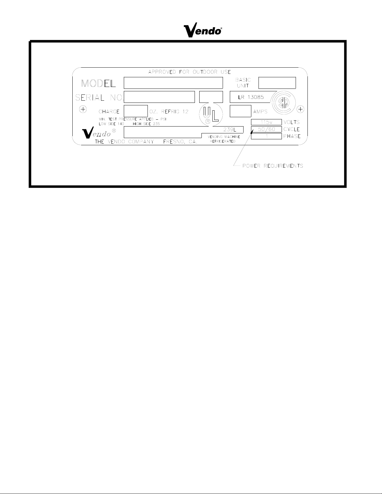
FIGURE 1
S-2
LOCK CODING
The safest method to code the lock is to remove it and secure it in a vise or similar tool. The
lock can also be recoded in the handle.
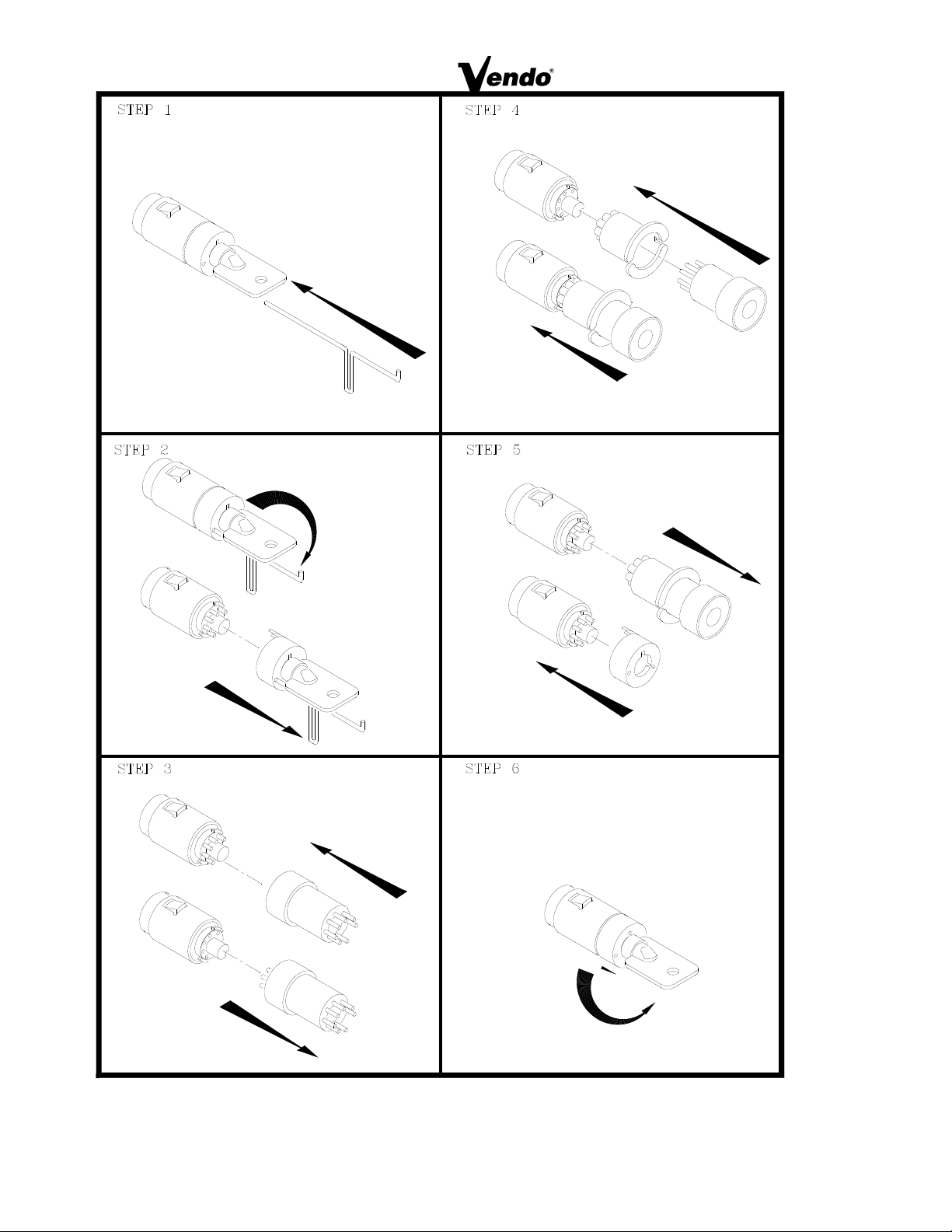
(For the following steps refer to Figure 2)
STEP 1
Insert key into lock. Insert pin into hole in cap.
STEP 2:
To release cap, push pin in firmly and rotate key to right slot position. Remove cap and key as
one unit.
STEP 3:
Using magnet end of loading tool, remove all seven tumblers.
STEP 4:
Slip preloaded coder on lock. Place loading tool into coder. Coder and tool will mount in one
direction only. Press new tumblers firmly into place.
STEP 5:
Remove coder and tool as one unit. Check to insure that all tumblers are in place. Replace
lock cap.
STEP 6:
Insert New key. Press cap in and rotate key counter clockwise left to locked position.
S-3
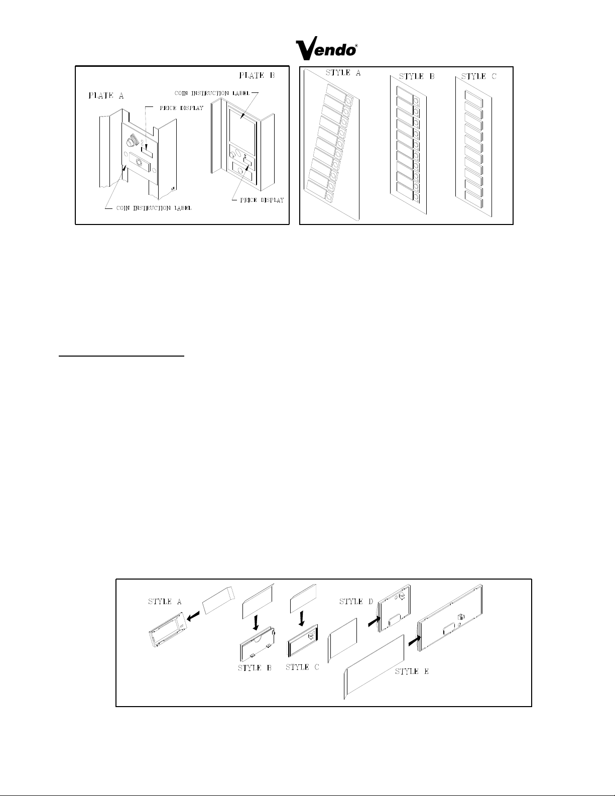
FIGURE 3 FIGURE 4
LABEL INSTALLATION
COIN INSTRUCTION LABEL & PRICE LABEL APPLICATION:
Apply labels to a clean and dry surface. Peel backing from label and apply to plate with a firm
even pressure.
INSTRUCTION LABEL
(Refer to figure 3 for the following information.)
Plate “A” has Validator Opening separate and above the Coin Plate “B” shows the Validator
Opening built in the Coin Plate. Apply Instruction Label to area shown (as needed by the
vendor).
FLAVOR LABELS INSTALLATION:
In figures 4 & 5, corresponding styles are indicated by A, B, C, D, or E notations.
Insert Flavor Labels to the side or top of Selection Window or Button depending on the style.
See Figure 4 for selection style. Rear view of windows and buttons is shown in Figure 5.
Arrows point the direction to insert labels.
Selection Window and Selection Button Labels identify product contained in stack columns.
FIGURE 5
S-4
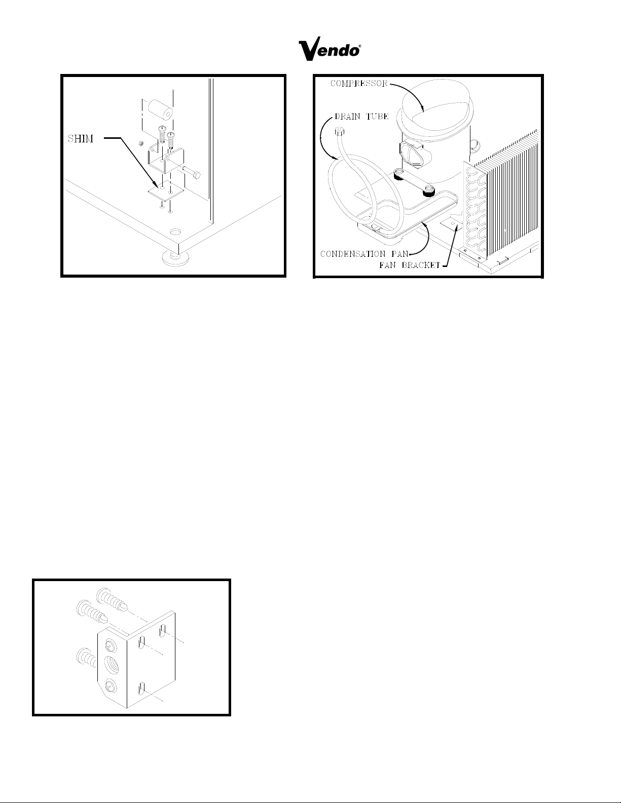
FIGURE 7 FIGURE 9
ALIGNMENT CHECKS
DOOR ROLLER CHECK:
The Door Roller assembly is raised or lowered by adding or removing shims, (see figure 7 ).
Raising or lowering the roller will help ensure the proper alignment of the door lockstud to the
cabinet latch.
DOOR ALIGNMENT CHECK:
After any door adjustment, the Quicker Lock should align itself automatically. If additional
adjustment is necessary, loosen mounting screws, (see Figure 8), raise or lower latch to the correct
position. Tighten mounting screws the floating nut of the Quicker Lock must be able to engage the
bolt of the T-handle.
REFRIGERATION AREA CHECK:
Check the position of the Condensation Pan, see Figure 9. The correct position of the Condensation
Pan is between the Compressor and the Condenser Fan Bracket. Be sure the Drain tube is clipped
to the pan and free of kinks. A loop must be maintained in the tubing. The loop prevents warm air
from reaching the evaporator area.
FIGURE 8
S-5

TEMPERATURE CONTROL
PRODUCT TEMPERATURE CHECK: (Reference only)
Allow vendor to run 24 hours. Vend product, insert test device (thermometer) into beverage.
TEMPERATURE CONTROL SETTING:
The temperature inside the cabinet is regulated by the Temperature Control, located on the left
side of the Evaporator (see Figure 10 ). Before adjusting control, make sure the refrigeration
system is working properly. Check that all fans run freely and do not make excessive noise.
Check that the vanes of the Evaporator are free of obstructions. Air flow over the vanes is
important for proper operation of the refrigeration unit. Check the door for a tight seal.
When the air temperature at the Capillary tube reaches 39 degrees Fahrenheit, the refrigeration
system will cycle on (see Figure 11). To decrease the temperature, turn the Temperature
Control Screw clockwise (see Figure 10). To increase the temperature, turn the screw counter-
clockwise. The temperature will change approximately 6 degrees with every 1/4 turn of the
control screw.
The Capillary tube is positioned in the air flow of the evaporator (see Figure 11). It must not
touch the rear of the cabinet wall or the evaporator shield (except at the clip). It is possible to
distort the position of the tube upon replacement and installation. If the refrigeration system is
replaced, check the Capillary tube’s position.
FIGURE 10 FIGURE 11
S-6
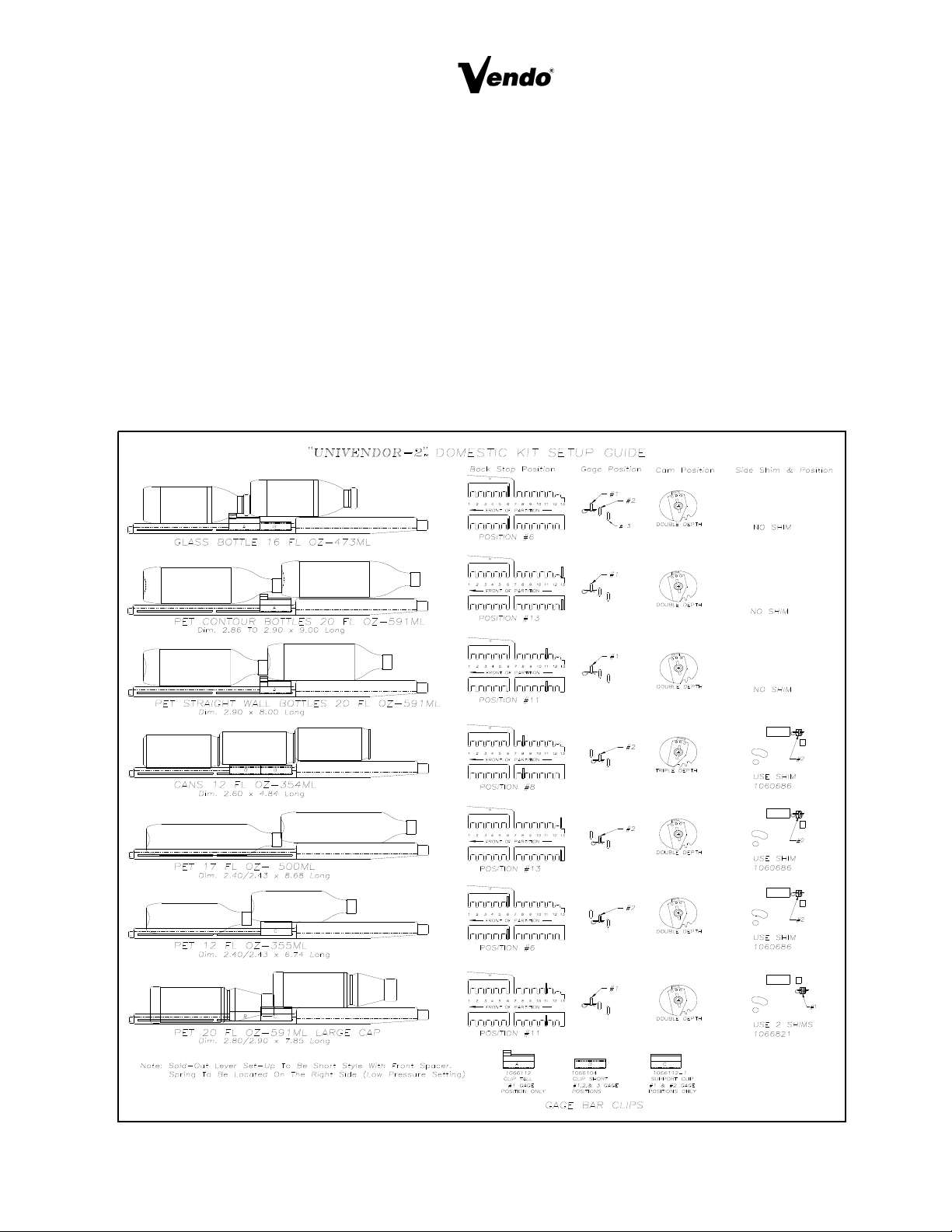
LOADING INSTRUCTIONS
BASIC LOAD SET-UP:
The Univendor-2 machine is capable of vending a variety of product. The Chart on page 7 is a
basic guide for the load set-up of these products. Refer to the chart and the items in Figure 12 for
each product’s setting and kits. Installation Instruction are included with each kit. Call a service
representative for kits or further information.
Open upper and lower product cage assemblies at front of stack to load product in columns. Load
product evenly. Bottles are loaded with crown end placed toward the back of the column. After
filling columns, close product cage assemblies. In initial loading, prime the machine by advancing
the product into the buckets. To advance product, insert proper coins and push the selection button
of the column you wish to prime. When the bucket is loaded the column is ready to vend. Prime all
columns.
FIGURE 12
S-7

VEND MECHANISM PARTS DESCRIPTION
The parts listed below are part of the Vend Motor Mechanism (refer to Figure 17 on page A6).
One Mechanism is required per column. The parts are interchangeable. Setting will differ
between single, double or triple depth.
MOTOR: P/N 388637
This motor is a thermal protected, 115 volt, 60 hertz, shaded pole motor. The motor has an
externally mounted spring loaded mechanical brake. The Motor is attached to the Mech. Plate
by three screws.
MOTOR CAM: P/N 390360
The Motor Cam assembly consists of two parts, the Cam and the Cam Retainer The Cam
controls the Motor Carrier and the Start/Bypass Switches. The Cam is Attached to the Motor by
the Cam Retainer (Retainer P/N 389401). The Retainer rotates left or right, provides for single,
double, or triple depth operation. (see page S-7 for Cam Settings)
MOTOR CARRIER SWITCH: P/N 388687
Two switches are located below the Motor Cam. The outside switch is the motor carrier switch.
This switch holds the motor on though the vend cycle. The motor stops when the motor Carrier
switch drops out.
SOLDOUT SWITCH: P/N 368299 / BASE SWITCH: P/N 388303
There is one Soldout Switch and one Base Switch above the Vend motor. The Soldout Switch is
actuated by the Soldout flap when the column is empty. It stops the motor from running. When
all columns are empty the Electronic Control stops the coinage from accepting money.
SELECTION SWITCH: (See part Section of the Manual for P/Ns.)
The selection switch sends power to a Vend Motor when a Customer Presses a Selection
Button. The Selection Switches are beneath the Selection Button/Windows.
VEND BUCKET: P/N 1060139
The Vend Bucket holds the product(s) in a ready to vend position at the base of each column.
ADAPTER COUPLING: P/N 1027042
The Adapter coupling couples the motor to the bucket. It is located behind the motor, on the
motor shaft.
ANTI-TILT CLIP: P/N 389712
The Anti-Tilt Clip prevents product from dropping out of the Bucket if the Vendor is tilted. The
Clip is located in the bucket.
S-8
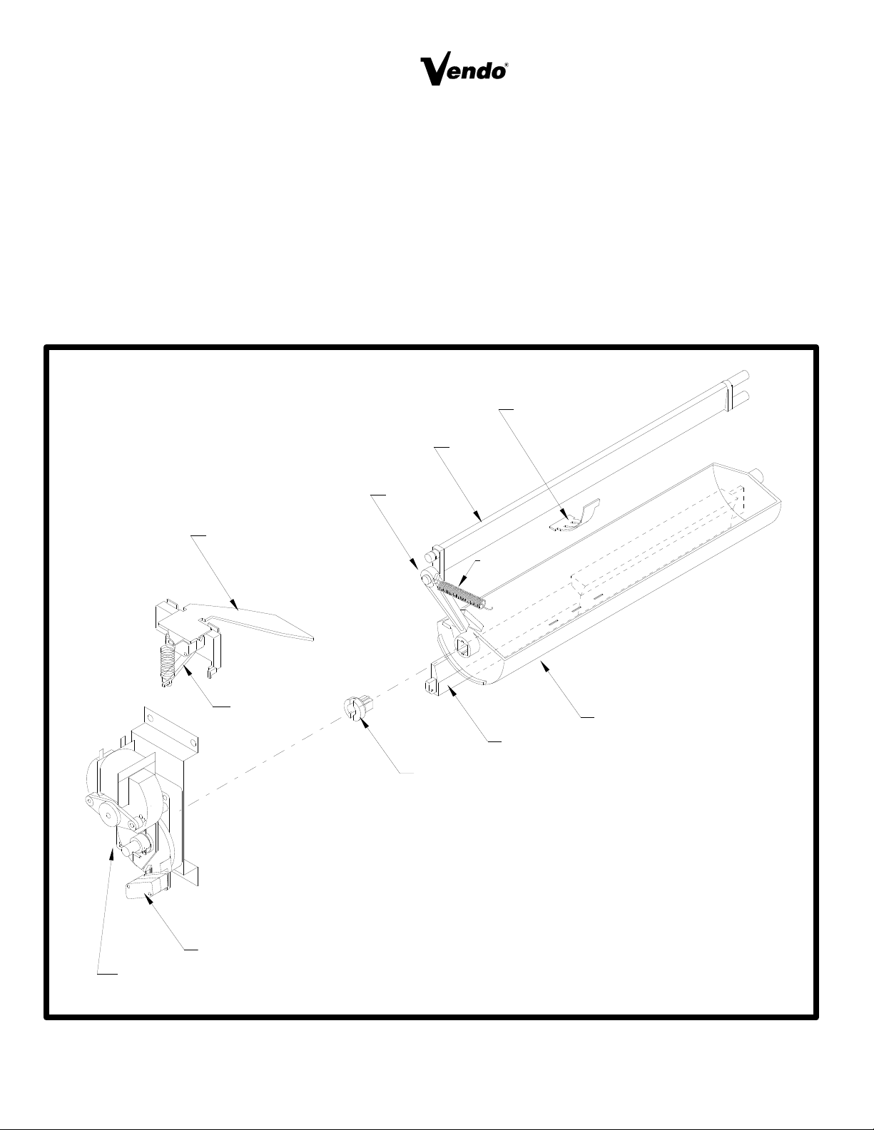
GATE: P/N 1066082
The gate holds product above the Vend Bucket.
GATE LINK: P/N 1008501
The rotation of Vend Bucket moves the gate link, this opens the gate allowing one layer of product
to drop into the bucket.
GAUGE BAR: P/N 1064333
The Gage Bar Holds the product (s) inside the bucket. It also regulates which product is vended
first when Double or Triple depth setting are used (See page S-7 for setting).
FIGURE 13
GATE
ANTI-TILT CLIP
SPRING
SOLDOUT LEVER
GATE
LINK
GAGE BAR
BUCKET
MOUNT
MOTOR CAM
MOTOR CARRIER SWITCH
SWITCH
COUPLING
S-9
VEND CYCLE
Several operations take place during the Vend Cycle: a purchase is made, the cam and bucket
rotate, product is dispensed and reloaded. The sequence of these operations change slightly
when the column’s depth setting is changed. With the Single Depth Setting, one purchase is
made and the bucket is reloaded, the Cam Sequence occurs once per bucket revolution. With
the Double Depth setting, two purchases are made before the Bucket is reloaded, the Cam
Sequence occurs twice per bucket revolution. With Triple depth setting, three purchases are
made.
PURCHASE SEQUENCE:
PS 1. Customer insert money.
PS 2. The Coinage Unit sends a signal energizing the Credit Relay. This creates a path of
power for the Selection Switch.
PS 3. Customer presses a Selection Button.
PS 4. The chosen Selection Switch closes, creating a path of power to energize a Vend
Motor.
PS 5. The Vend Motor turns the Bucket and Cam.
PS 6. Product is Immediately dispensed.
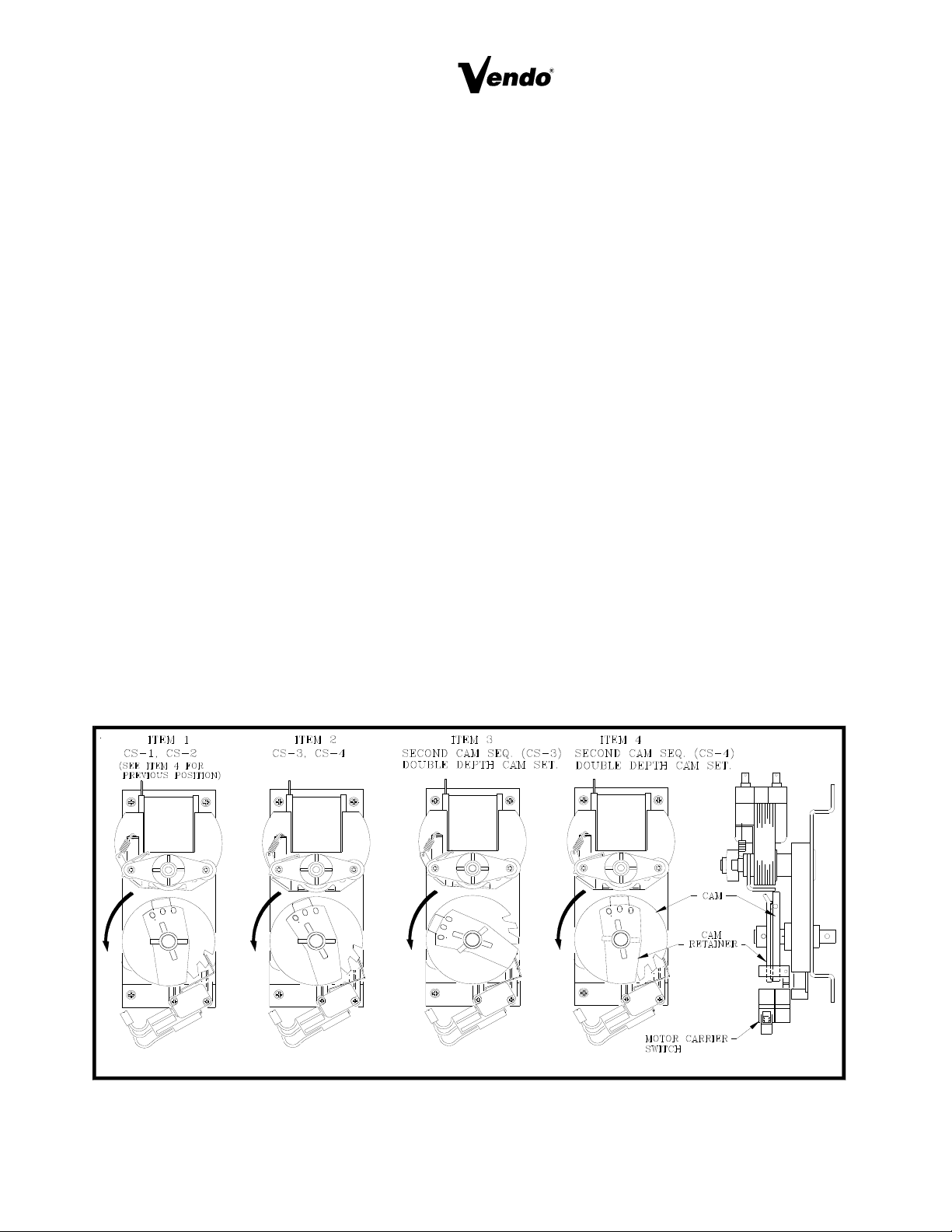
CAM SEQUENCE: (See Figure 14, Double depth Setting Pictured)
CS 1. As the Motor turns the Cam, the Switch falls into the low part of the cam. This interrupts
the power path to the Credit relay canceling credit.
CS 2. Simultaneously, the Motor Carrier Switch is lifted to the high part of the cam. This
provides an alternate path of power, to the Vend Motor.
CS 3. With the Cam still rotating, the Switch lifts back to the part of the Cam, (permitting
another purchase when it is required).
CS 4. The Motor Carrier Switch falls into the lower part of the Cam, cutting power to the Motor.
The Motor stops.
FIGURE 14
S-10
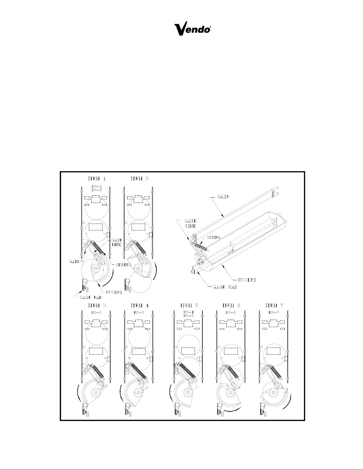
RELOADING SEQUENCE: (See Figure 15)
RS 1. The gate link rests at a locked position, in a cutout on the mech. plate. This locked
position prevents the gate from opening out of sequence.
RS 2. The gate link is guided by a slot in the mech. plate and actuates by a ridge on the
bucket. As the bucket turns, the link is moved out of the locked position.
RS 3. As the link rises, the gate is opened. The spring maintains Pressure on the Link and the
gate.
RS 4. Product falls onto outside of the bucket.
RS 5. The bucket releases the gate link causing the gate to rest against the product.
RS 6. As the product falls into the bucket, the link returns to the locked position and the gate is
closed.
RS 7. The product remaining in the column is caught by the closed gate, keeping it above the
bucket.
RS 8. Bucket stops, product is Ready to vend.
FIGURE 15
S-11

LIGHTING WIRING DIAGRAMS
REFRIGERATION WIRING DIAGRAM
S-12

REFRIGERATION OPERATION
The refrigeration operation section is divided into three areas: Basic Refrigeration Principle.
Detailed Vending machine Refrigeration cycle, and Parts Description.
BASIC REFRIGERATION PRINCIPLE
What a refrigeration system really accomplishes is the transfer of heat. A refrigeration system
removes the excess heat from a refrigerated area and then transfers it to a condenser where it is
dissipated. As heat is removed, the refrigerated area cools.
In vending machines, large quantities of the heat must be transferred rapidly, economically and
efficiently. This process must be able to withstand continuous repetition, without loss of refrigerant,
over an extended period. The most common system used in the vending industry is the vapor
compression (or simple compression) cycle system. It consists of four basic elements: an
evaporator, a compressor, a condenser, and a pressure reducing restricted (all part of a sealed
system).
The compression system operates at two pressure levels: the low evaporating pressure and the
high condensing pressure. The refrigerant acts as the transport medium, in which heat is moved
from the evaporator to the condenser; at the condenser, the heat is dissipated into the surrounding
air.
The liquid refrigerant changes from a liquid, to a vapor and back to a liquid again. This change of
state allows the refrigerant to absorb, and rapidly discharge, large quantities of heat efficiently.
BASIC VAPOR COMPRESSION SYSTEM CYCLE DESCRIBED:
In the evaporator the liquid refrigerant vaporizes. This change occurs at a temperature enough to
absorb heat from the refrigerated space. The temperature of vaporization is controlled by the
pressure maintained in the evaporator (the higher the pressure, the higher the vaporization point).
The compressor pumps the vapor from the evaporator, through the suction line, and to the
condenser. The compressor takes the low pressure vapor and compresses it, increasing both the
pressure and the temperature. The compressor pumps the vapor at a rate rapid enough to maintain
the ideal pressure. The hot high pressure vapor is forced out of the compressor, into the discharge
line and then into the condenser.
Air is blown through the condenser, allowing heat to transfer from the condenser and into the
passing air. As the heat is removed, the stored refrigerant is condensed into a liquid. The liquid
refrigerant is stored in the lower tube of the condenser. It is there, available to flow through the
restricter tube, back into the evaporator, where the refrigeration cycle is repeated.
S-13

DETAILED REFRIGERATION CYCLE
The following is a detailed refrigeration cycle as it applies to the refrigeration system installed in
Vendo equipment. (Refer to the flow chart in Figure 16)
As the temperature in the cabinet rises, the liquid in the thermostat feeler bulb also rises in
temperature. As this liquid becomes warmer, it expands. This expanding liquid expands against
the temperature control bellow which operates the temperature control switch. The temperature
control switch turns on both the compressor and condenser fan.
The evaporator fan pulls air from the front of the refrigerated space of the cabinet. It pulls the air
through the evaporator, and blows it up the back of the vend stack. (The evaporator fan runs
continuously.) As the air passes through the evaporator, heat is draw from the air and
transferred to the liquid refrigerant. As the cooled air circulates through the vend stack, heat is
drawn from the product and transferred to the circulating air. The heated air is again drawn
through the evaporator where the heat is removed.
In the evaporator, the liquid refrigerant draws heat from the circulating air. As refrigerant
receives heat, it vaporizes.
The compressor pumps the vapor from the evaporator and compresses it (increasing both
pressure and temperature). The compressor forces the compressed vapor out, through the
discharge line and into the condenser.
The condenser fan pulls air through the condenser. As the hot refrigerant vapor passes through
the condenser tubes, heat is drawn from the vapor. This heat is dissipated into the passing air,
the air then exits out the back of the vendor. As the refrigerant vapor in the condenser lines is
cooled, it returns to a liquid state.
From the condenser the liquid flows to the drier. The drier removes any water and solid particles
from the liquid refrigerant.
The cooled liquid refrigerant continues from the drier, through the capillary tube, to the
evaporator. The capillary tube steadies the flow rate of the refrigerant. Its small inside diameter
allows the pressure in the evaporator to remain low while the pressure in the condenser is high.
The cool refrigerant in the evaporator draws heat from the circulating air in the cabinet. As the
temperature in the cabinet drops, the liquid in the thermostat feeler bulb cools and condenses.
The condensed liquid releases the pressure against the thermostat control bellows, de-actuating
the temperature control switch. The deactuated control switch turns off the compressor and
condenser fan.
When the temperature in the cabinet rises above the thermostat’s setting, the compressor and
the condenser fan engage again. The refrigeration process is continuous as long as the
compressor operates.
S-14
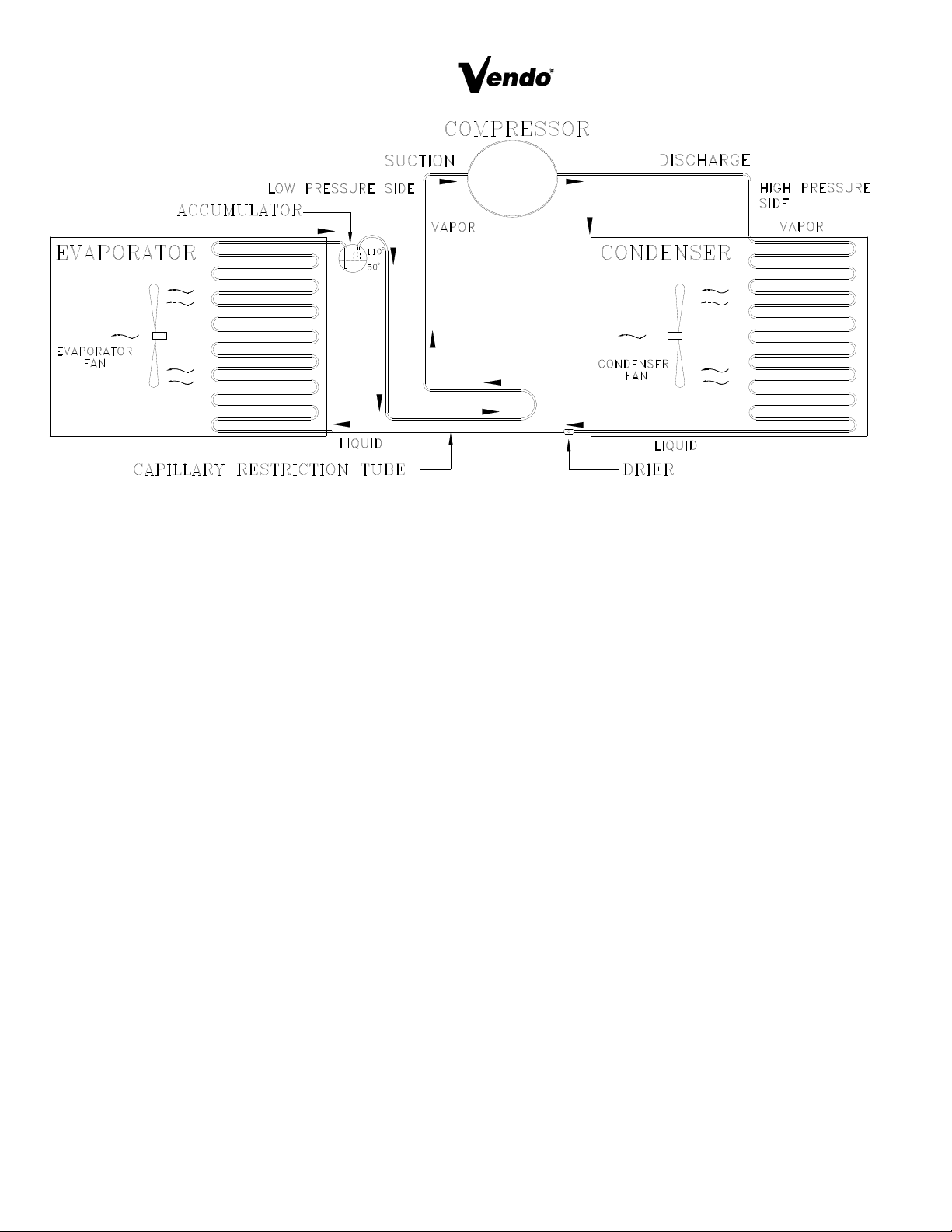
FIGURE 16
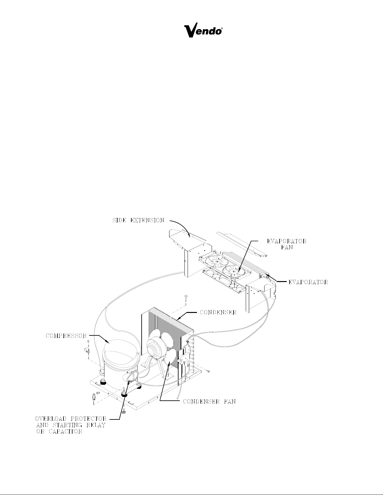
REFRIGERATION PARTS DESCRIPTION
The Compressor, Condenser, Drier, Capillary Tube, Evaporator, and Accumulator are part of
a sealed system (refer to figure 16). These items are not available separately. For the part
number of the sealed refrigeration system refer to the common parts section of the manual.
COMPRESSOR
The compressor takes in low pressure vapor and compresses it, increasing both the pressure and
the temperature. The hot high pressure gas is forced out to the condenser. The compressor and
the motor that drives the compressor are sealed inside a housing. The compressor, as a unit, is
mounted on the refrigeration base. The base is mounted in the bottom of the vendor, outside the
sealed refrigeration space.
CONDENSER
The condenser takes heat out of the high pressure vapor that it receive from the compressor. As
the vapor passes through the condenser it cools and returns to a liquid state. The condenser is
mounted to the refrigeration base near the front of the vendor. It is easily accessible for cleaning.
DRIER
The Drier is a molecular sieve strainer drier. It removes water and solid particles from refrigerant
liquid. One side of the dryer is connected to the outlet line of the condenser; the other side is
connected to the capillary tube going to the evaporator.
S-15
REFRIGERATION PARTS DESCRIPTION (CONTINUED)
CAPILLARY TUBE
The capillary tube controls, at a steady rate, the flow of refrigerant liquid to the evaporator. It has
a very small inside diameter to keep pressure in the evaporator low while the pressure in the
condenser is high. It is the connecting link between the condenser and evaporator.
EVAPORATOR
The Evaporator is a heat transference device. It removes the heat from the air in a refrigerated
space and transfers it to the refrigerant liquid. This liquid evaporates into a vapor and is sucked
out by the compressor. The evaporator is mounted inside the refrigerated space of the cabinet,
directly below the delivery chute.
ACCUMULATOR
The accumulator traps any refrigerant liquid which did not boil off into a vapor before reaching the
compressor. The accumulator allows the refrigerant liquid to boil off as a vapor (preventing
damage to compressor). It also prevents suction line sweating. The accumulator is mounted in
the suction line on the outline side of the evaporator.
FIGURE 17
S-16

(The parts listed below are not part of the sealed refrigeration system and are available separately.
For part numbers, see the refrigeration assembly in the common parts section of the manual.)
CONDENSER FAN ASSEMBLY
The condenser fan pulls cool air from outside the vendor, through the condenser, over the
compressor and blows it out the back of the vendor. This cool air removes excess heat from
refrigerant in the condenser. The condenser fan runs when the compressor is engaged. The fan
assembly is mounted on the refrigeration base between the condenser and compressor.
EVAPORATOR FAN ASSEMBLY
The Evaporator fan pulls air from the front of the refrigerated space, through the evaporator, up the
rear of the refrigerated space into the vend stack. The fan blows air through the evaporator (which
removes the heat from the air). It circulates the cool air over the product, removing excess heat
from the product. The evaporator fan assembly is mounted to a fan bracket, mounted to the
extensions of the evaporator. These parts are located in the refrigerated area of the cabinet.
TEMPERATURE CONTROL
The temperature control regulates the temperature inside the refrigerated space of the vendor. The
control is adjustable. The temperature control consist of two main parts: the temperature control
box and the thermostat feeler bulb. The control box is mounted to the side of the evaporator. The
bulb is mounted on the evaporator fan bracket, in the air flow of fan. The bulb is a very narrow tube
with a refrigerant liquid inside. Small tubing connects the bulb to the control box. As liquid in the
feeler bulb warms, it expands into the tubing and then into the control box, pressing against a
bellows. The bellows closes a switch in temperature control, activating the compressor and the
condenser fan. As the liquid in the feeler bulb cools it contracts and releases the pressure against
the bellows, opening the switch, deactivating the compressor and the condenser fan.
START CAPACITOR - (WHEN USED)
The start capacitor is used on start up of the refrigeration system to phase out excess power to and
from the refrigeration system.
STARTING RELAY
The starting relay is mounted in the terminal box on the side of the compressor housing. When the
compressor first starts up, the starting relay closes and completes a starting circuit. When the
compressor motor reaches operating speed, the starting relay opens and breaks the starting circuit.
THERMAL OVERLOAD SWITCH
The thermal overload switch is mounted in the terminal box on the side of the compressor housing.
If the compressor motor gets hot or draws too much current, the thermal overload opens and breaks
the starting and running circuit of the motor. As the motor cools, the thermal overload closes,
allowing the compressor to run.
S-17
MAINTENANCE
The following section is a basic guide for general maintenance and servicing of the Vendor . This
section is divided into four parts: (I) Preventative Maintenance, (II) Lubrication Guide, (III) Care
and Cleaning, (IV) Basic Trouble Shooting.
I. PREVENTATIVE MAINTENANCE SUGGESTIONS:
When ever a Vendor is visited on its site, the following service should be performed.
Preventative maintenance will help prevent future problems with the Vendor.
A. Observe the Vendor and its surrounding area for any unusual indications of problems
(rear on cabinet, obstructions of the air flow, dark spots on the sign face, etc.)
B. Open the door and visually check the inside of the Vendor (water accumulation, rust
marks, moisture around the edges of the inner door, etc.)
C. Check the fluorescent lamps, replace as necessary. Replace single pin (slimline) lamps
within 24 to 48 hours of burnout. This will prevent damage to ballast.
D. Check the product temperature for proper cooling.
E. Check evaporator drain for obstruction; water in the evaporator area must drain to the
condensate pan.
F. Empty condensate pan.
G. Clean the condenser, free vanes of dirt, lint, etc.
H. Check evaporator fan(s) run normally.
I. Check the Compressor and condensate fan run normally.
J. Investigate any unusual sounds (fan blades hitting something, refrigeration lines rattling,
etc.)
K. Clean coin acceptor.
L. Deposit all coinage accepted by the Vendor to check for proper operation of the coinage
mechanism.
M. Test the Vendor and make a report on the problems,
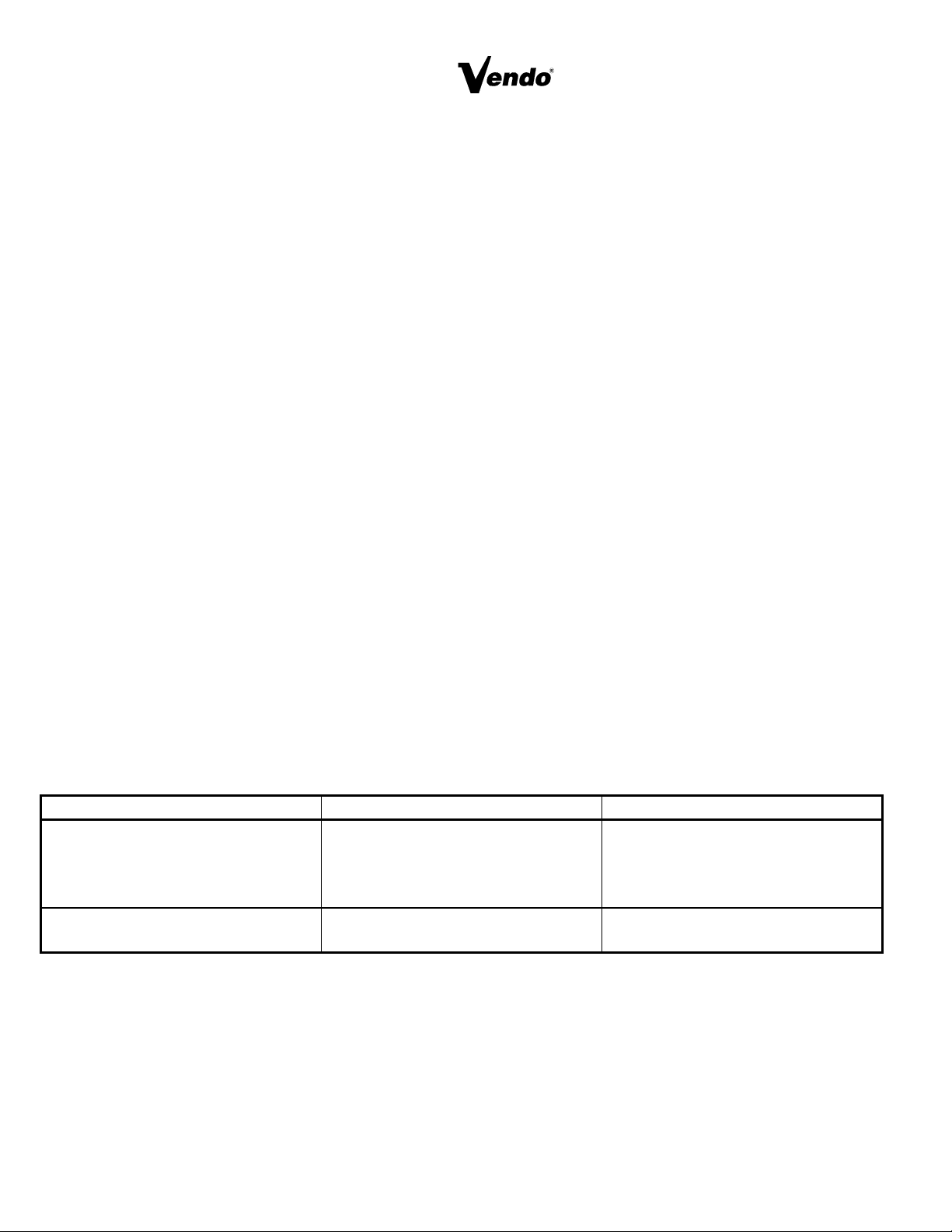
II. LUBRICATION GUIDE:
Lubricate indicated areas as directed on the chart below.
INTERVALS PARTS LUBRICANT
Every six months Top hinge of door door hinge
pin at the base of cabinet door
latch cam to cabinet strike T-
handle shaft & latch.
Grade two, high low
temperature grease
As necessary Pivot area of bucket and gate Grade two, high low
temperature grease
S-18

III. CARE AND CLEANING
A. GENERAL PROCEDURE ( painted metal areas)
Wash Vendor with soap and water. The exterior may be waxed with any good
automobile wax.
B. FRESH PAINT SPLASHES, GREASE, GLAZING COMPOUND REMOVAL
Before drying, these elements may be removed by rubbing lightly with grade “A” Naptha
(or equivalent grade solvent). After removal, use general cleaning procedure (listed
above as A)
C. LABELS AND STICKER REMOVAL
Use Kerosene, VM&P grade Naptha or petroleum spirits for removal. When the label
material does not allow penetration of solvent (such as vinyl) the application of heat
(hair blow dryer) will soften the adhesive and promote removal. CAUTION: Excessive
heat can cause surface damage. After the label is removed, use the general cleaning
procedure (listed above as A).
D. SCRATCH REMOVAL
Remove or minimize hairline scratches and minor abrasions by using any good quality
automobile polish. Test product before using.
E. LEXAN SIGNS
To clean Lexan sign faces the following procedure is recommended.
1. Wash sign with mild soap or detergent and lukewarm water.
2. Using soft cloth or sponge, gently wash the sign. DO NOT SCRUB!
3. Rinse well with clean lukewarm water.
4. Dry thoroughly with a chamois or cellulose sponge (to prevent water spotting). DO
NOT USE SQUEEGEE!
NOTE: Most organic solvents, petroleum, spirits, or alcohol are NOT compatible cleaning
materials for lexan signs. Usage of those materials could permanently damage the
sign.
F. REFRIGERATION AREA
The condenser and evaporator must be kept clean for efficient operation. Be sure all
vanes and tubing are clean and clear of obstruction; This allows free passage of air.
Clean with a brush, a vacuum cleaner or compressed air. Keep cabinet drain open;
clean as necessary.
S-19
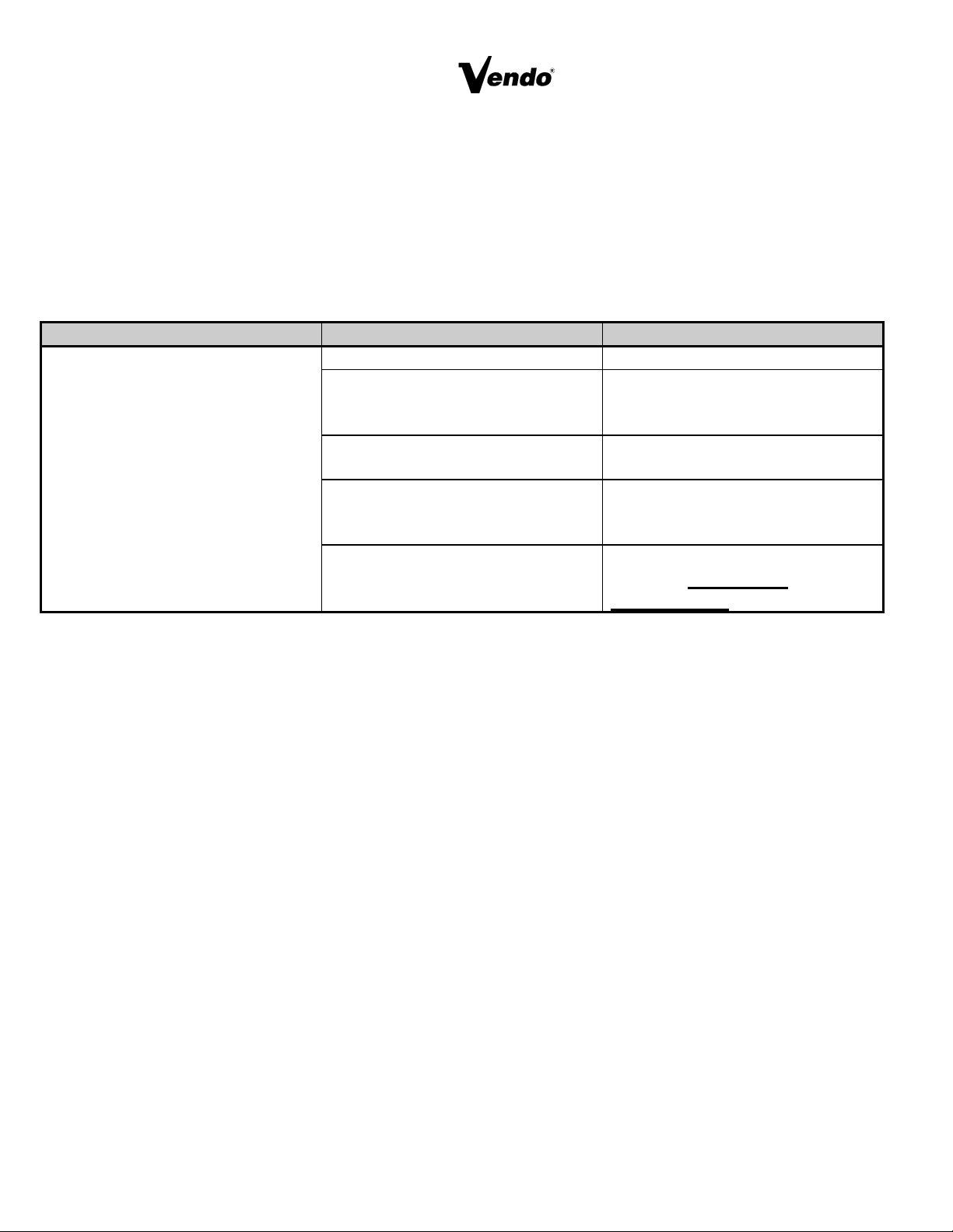
TROUBLE-SHOOTING GUIDE
This guide is a general list of probable problems, causes, and solutions. For problems
not listed or additional question, contact the Field Service Department at Vendo, 7209
N. Ingram Ave., Fresno, CA 93650 or call 1-800-344-7216. Please have the
maufacturer’s date code and model number of the vendor when you call.
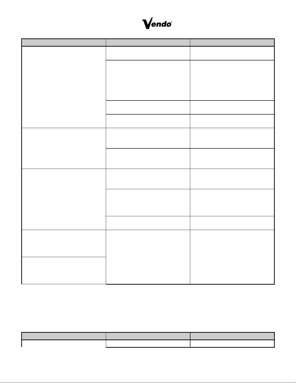
The trouble-shooting guide is divided into three columns: First Column, Possible
Problem; Second Column, Possible Cause; Third Column, Service Suggestion.
POSSIBLE PROBLEMS POSSIBLE CAUSE SERVICE SUGGESTION
Returns all good coins No power to vendor Check power Supply
No power to changer Check coin mechanism plugs
check for faulty harness wiring
(see wiring diagram for circuit)
Acceptor is out of adjustment or
coin gate is not closed
Check coin mechanism
Electronic-CREM function: 1.)
No power to acceptor.
2.) Defective acceptor
1. Check electrical connections
of the acceptor.
2. Replace acceptor
Coin paths are dirty Clean acceptor with approved
cleaner. DRY VERY
THROUGHLY
S-20
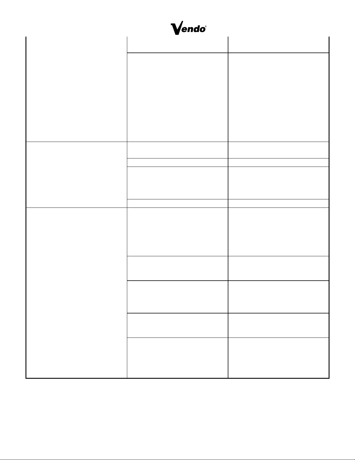
POSSIBLE PROBLEM POSSIBLE CAUSE SERVICE SUGGESTION
Money accepted no product
vended
No selections work Check No.1 selection switch,
replace if necessary.
No. 1 selection works, No. 2
thru last does not.
Check No 2. section switch,
replace it necessary. This
pattern can continues thru last
selection switch as selection
circuit goes from 1 to 2 to 3.
etc., to last
Soldout Switch (of column
selected) inoperative
Check switch, replace
Motor starts, does not run Check motor carrier switch,
replace switch
Vend motor runs until two or
three products are vended or
vend motors run continuously.
Improper cam lobe adjustment Check Cam for proper
arrangement of cam lobes
(see product set up guide)
Motor carrier switch not
making contact with cam lobe
or switch
Check lever for proper lever
positioning and freedom of
movement
Refrigeration unit will not run
at all
No power to vendor Check power supply also
check service cord
connections.
Thermostat open (temperature
control)
Check thermostat (Apply
insulated jumper across
terminals, if compressor starts,
replace thermostat)
Temperature control bulb out
of position
Check that bulb is in air flow
Compressor will not start Overload Protector
Inoperative
Check overload (apply
insulated jumper across
terminal, if compressor starts,
replace overload)
Compressor will not start
condenser fan motor running,
unit cool (no power to
compressor)
POSSIBLE PROBLEM POSSIBLE CAUSE SERVICE SUGGESTION
Compressor will not start, Starting relay or capacitor Check relay or capacitor
S-21
condenser fan motor running -
unit hot (power to compressor)
inoperative replace
Compressor inoperative Disconnect power to vendor,
remove all leads from
compressor, check continuity
from “common”, “start” and
“run” to compressor case. If
continuity shows, replace
compressor. Also Check from
“common to start”. (using
continuity or IHMS.) If meter
fails to show reading replace
compressor.
Compressor starts but does
not run
Will not cycle Check overload and contact,
replace overload if necessary
Starting relay stays closed Replace relay
Thermostat inoperative Check thermostat clean
contacts with approved
electrical cleaner. Replace
thermostat it necessary
Compressor motor problem Check, replace
Compressor runs but cabinet
temperature warm
Loss of refrigerant Replace refrigeration unit
(Note: any work of this nature
done without express
permission from The Vendo
Company can void
refrigeration unit warranty)
Condenser fan not working Check circuit to run motor.
Replace motor. Check for
obstruction of fan blade.
Blocked or dirty condenser
(refer to initial installation in
the service manual)
Check condenser vanes for
obstruction, lint or dirt. Clean,
also check for proper air flow
through refrigeration area.
Evaporator fan not working Check circuit to fan motor.
Replace motor also check for
obstruction of fan blade
Bad inner door seal Check for moisture on seal.
Adjust inner door as
necessary (see initial setup of
service manual). Replace
door seal.
S-22
S-23
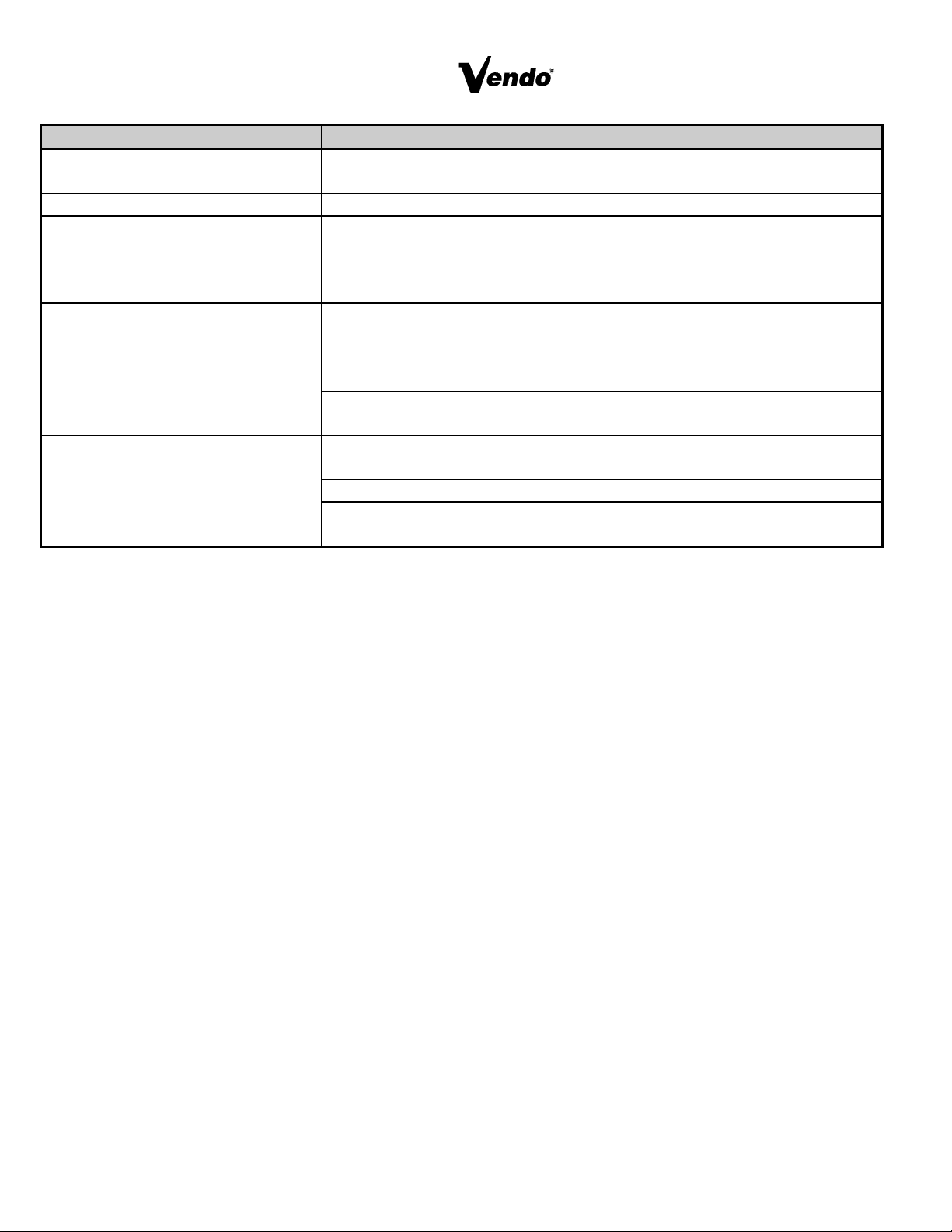
POSSIBLE PROBLEM POSSIBLE CAUSE SERVICE SUGGESTION
Compressor runs, but cabinet
temperature warm
Thermostat set too high Adjust thermostat (see initial
set up of service manual)
Compressor runs continuously Thermostat inoperative Check thermostat
Evaporator frosted over Water at base of evaporator
unit
Check for proper drainage
(such as plugged drain, kinks in
drain tube, etc.) check door
seal
Product freezing up too cold Thermostat set too low Adjust thermostat (See intial set
up of service manual)
Thermostat inoperative
(compressor runs continuously)
Check thermostat replace if
necessary
Thermostat feeler bulb out of
position
Adjust feeler bulb (see initial set
up of service manual)
Excessive noise Fan blade bent or hitting shroud Straighten, relocate shroud
position, or remove shroud.
Fan motor noisy Replace if necessary
Refrigeration base loose or
bent
Tighten bolt or replace if
necessary

A COMMITMENT TO SAFETY
The Vendo Company is committed to safety in every aspect of our product design. Vendo
is committed to alerting every user to the possible dangers involved in improper handling
or maintenance of our equipment. The servicing of any electrical or mechanical device
involves potential hazards, both to those servicing the equipment and to users of the
equipment. These hazards can arise because of improper maintenance techniques. The
purpose of this manual is to alert everyone servicing Vendo equipment of potentially
hazardous areas, and to provide basic safety guidelines for proper maintenance.
This manual contains various warnings that should be carefully read to minimize the risk
of personal injury to service personnel. This manual also contains service information to
insure that proper methods are followed to avoid damaging the vendor or making it unsafe.
It is also important to understand these warnings are not exhaustive. Vendo could not
possibly know, evaluate, or advise of all of the conceivable ways in which service might be
done. Nor can Vendo predict all of the possible hazardous results. The safety precautions
outlined in this manual provide the basis for an effective safety program. Use these
precautions, along with the service manual, when installing or servicing the vendor.
We strongly recommend a similar commitment to safety by every servicing organization.
Only personnel properly trained in vendor servicing should have access to the interior
of the machine. This will minimize the potential hazards that are inherent in electrical and
mechanical devices. Vendo has no control over the machine once it leaves the premises.
It is the owner or lessor’s responsibility to maintain the vendor in a safe condition. See
Section I of this manual for proper installation procedures and refer to the appropriate
service manual for recommended maintenance procedures. If you have any questions,
please contact the Technical Services Department of the Vendo office nearest you. Refer
to the listing at the back of this manual.
SAFETY RULES
• Read the Safety Manual before installation or service
• Test for proper grounding before installing to reduce the risk of electrical shock and fire.
• Disconnect power cord from wall outlet before servicing or clearing product jams. The
vending mechanism can trap and pinch hands.
• Use only fully trained service technicians for “Power On” servicing.
• Use adequate equipment when moving a vendor.
• Always wear eye protection, and protect your hands, face, and body when working
near the refrigeration system.
• Use only authorized replacement parts.
• Be aware of inherent dangers in rocking or tipping a vending machine.
Page 1

SECTION I: VENDOR INSTALLATION
A. Vendors are large, bulky machines of significant size and weight. Improper
handling can result in injury. When moving a vendor, carefully plan the route to be
taken and the people and equipment required to accomplish the task safely.
B. Remove all tape, shipping sealant, and Styrofoam from the vendor. Loosen any
shipping devices used to secure interior parts during shipping. Remove the wooden
shipping base, attached to the vendor base by the vendor leveling screws. Make
certain the leveling screws are in place and functional.
C. Position the vendor three to four inches (7.6 cm to 10.2 cm) from a well-constructed
wall (of a building or otherwise) on a flat, smooth surface.
IMPORTANT: The vendor requires three inches (7.6 cm) of air space from the wall
to ensure proper air circulation to cool the refrigeration unit.
D. Adjust the leveling screws to compensate for any irregularities on the floor surface.
Ideally, no adjustment will be necessary and the leveling legs will be flush with the
bottom of the vendor. A spirit level is a useful aid to level the vendor. When the
vendor is properly leveled, the outer door, when opened, will remain stationary.
Vendors must be level to assure proper operation and to maintain stability
characteristics. Do not add legs to the vendor.
E. Check the manufacturer’s nameplate on the left or right side of the vendor outer
door to verify the main power supply requirements of the vendor. Be sure the main
power supply matches the requirements of the vendor. To ensure safe operation,
plug the vendor only into a properly grounded outlet. DO NOT USE EXTENSION
CORDS.
NOTE: Any power supply variance more than +
10% may cause vendor to malfunction.
* Power outlets must be properly grounded.
* Power outlets must be properly polarized, where applicable.
Test the outlets using the following information. (Refer to Figure 1 on Page
3.)
Page 2
 Loading...