

Page 1

Parts & Service Manual
For ALL V21 Identified Equipment
SandenVendo America, Inc.
10710 Sanden Drive, Dallas, TX 75238
T: 800-344-7216 F: 800-541-5684
T: 214-765-9066 F: 214-340-8029
www.vendoco.com
FOR TECHNICAL ASSISTANCE,
PLEASE CALL:
1-800-344-7216 EXT-1036
Page 2

V21 Parts & Service Manual
All V21 Identified Equipment
REV A – 10/2013
P/N: 1230212
TABLE OF CONTENTS
SAFETY SECTION ………………………………………………
Pages S-1 – S-15
A COMMITMENT TO SAFETY …………………………………………
Page S-2
VENDOR INSTALLATION ………………………………………………….
Pages S-3 – S-6
ELECTRICAL HAZARDS ……………………………………………………..
Pages S-7 – S-8
MECHANICAL HAZARDS ………………………………………………….
Page S-9
REFRIGERATION HAZARDS ……………………………………………
Page S-10
SUBSTITUTIONS & MODIFICATIONS ……………………………….
Pages S-11 – S-12
CONSUMER SAFETY WARNING ……………………………………….
Page S-13
PARTS, SALES, & SVA SERVICE CENTERS …………………………
Pages S-14 – S-15
GENERAL INFORMATION …………………………………….
Pages G-1 – G-15
GENERAL INFORMATION ………………………………………………...
Page G-2
INITIAL SET-UP …………………………………………………………………
Pages G-3 – G-4
LABEL INSTALLATION CHAMELEON ………………………………..
Page G-5
LABEL INSTALLATION TRADE …………………………………………..
Page G-6
LABEL INSTALLATION HV3 ………………………………………………
Page G-7
LABEL INSTALLATION HVV ………………………………………………
Page G-8
ALIGNMENT CHECKS ……………………………………………………….
Page G-9
LOADING INSTRUCTIONS ………………………………………………..
Pages G-10 – G-11
VEND MECHANISM PARTS DESCRIPTION ……………………….
Pages G-12 – G-13
VEND CYCLE …………………………………………………………………….
Pages G-14 – G-15
12.4 PROGRAMMING HV3 / CHAMELEON ….……….....
Pages P1-1 – P-14
12.4 PROGRAMMING ………………………………………………………
Page P1-2
SET-UP & CODE DESCRIPTION ………………………………………..
Pages P1-3 – P-12
12.4 WIRING DIAGRAMS ………………………………………………….
Page P1-13
SPACE-TO-SALES………………………………………………………………
Pages P1-14
12.4 PROGRAMMING COKE CHAMELEON ….………......
Pages P2-1 – P2-18
12.4 PROGRAMMING ………………………………………………………
Page P2-2
SET-UP & CODE DESCRIPTION ………………………………………..
Pages P2-3 – P2-16
12.4 WIRING DIAGRAMS ………………………………………………….
Page P2-17
SPACE-TO-SALES………………………………………………………………
Pages P2-18
12.1 PROGRAMMING TRADE …………………….………...
Pages P3-1 – P3-18
12.1 PROGRAMMING ………………………………………………………
Page P3-2
SET-UP & CODE DESCRIPTION ………………………………………..
Pages P3-3 – P3-15
12.1 WIRING DIAGRAMS ………………………………………………….
Page P3-16 – P3-18
12.3 PROGRAMMING HVV ….....………………….………...
Pages P4-1 – P4-14
12.1 PROGRAMMING ………………………………………………………
Page P4-2
V21 Table of Contents | ii
Page 3

V21 Parts & Service Manual
All V21 Identified Equipment
REV A – 10/2013
P/N: 1230212
SET-UP & CODE DESCRIPTION ………………………………………..
Pages P4-3 – P4-12
12.3 WIRING DIAGRAMS ………………………………………………….
Page P4-13 – P4-14
CABINET PARTS .………………………………………………..
Pages C-1 – C-22
READING A PARTS LIST ……………………………………………………
Page C-2
HARDWARE LIST ………………………………………………………………
Pages C-3 – C-6
CABINET ASSEMBLY CHAMELEON / TRADE / HV3 ….………
Pages C-7 – C-8
CABINET ASSEMBLY HVV .……………………………………………….
Pages C-9 – C-10
STACK ASSEMBLY ….……..………………………………………………….
Pages C-11 – C-12
MECH PLATE ASSEMBLY ………………………………………………….
Pages C-13 – C-14
621 / 721 / 821 REFRIGERATION ASSEMBLY …………………...
Page C-15
521 REFRIGERATION ASSEMBLY……………………………………….
Page C-16
621 / 721 / 821 C02 REFRIGERATION ASSEMBLY …………...
Page C-17
POWER BOX ASSEMBLY …………………………………………………..
Pages C-18 – C-19
HARNESS QUICK REFERENCE GUIDE ……………………………….
Pages C-20 – C-22
DOOR PARTS CHAMELEON ………………………………….
Pages D1-1 – D1-10
OUTER DOOR …………………………………………………………………..
Pages D1-2 – D1-7
LOCK ASSEMBLY ………………………………………………………………
Page D1-8
INNER DOOR ASSEMBLY …………………………………………………
Pages D1-9 – D1-10
DOOR PARTS CHAMELEON ADA …….…………………….
Pages D2-1 – D2-8
OUTER DOOR …………………………………………………………………..
Pages D2-2 – D2-5
LOCK ASSEMBLY ……………………………………………………………...
Page D2-6
INNER DOOR ASSEMBLY …………………………………………………
Pages D2-7 – D2-8
DOOR PARTS CHAMELEON LIVE DISPLAY ………………
Pages D3-1 – D3-9
LIVE DISPLAY OUTER DOOR ……………………………………………
Pages D3-2 – D3-5
LIVE DISPLAY ASSEMBLY …………………………………………………
Page D3-6
LIVE DISPLAY LOCK ASSEMBLY ……………………………………….
Page D3-7
LIVE DISPLAY INNER DOOR ASSEMBLY …………………………..
Pages D3-8 – D3-9
DOOR PARTS TRADE …………………………………………..
Pages D4-1 – D4-15
OUTER DOOR …………………………………………………………………..
Pages D4-2 – D4-9
LOCK & TRANSACTION ASSEMBLY …………………………………
Pages D4-10 – D4-13
INNER DOOR ASSEMBLY …………………………………………………
Pages D4-14 – D4-15
DOOR PARTS TRADE ADA ……………………………………
Pages D5-1 – D5-15
OUTER DOOR …………………………………………………………………..
Pages D5-2 – D5-9
LOCK & TRANSACTION ASSEMBLY …………………………………
Pages D5-10 – D5-13
INNER DOOR ASSEMBLY …………………………………………………
Pages D5-14 – D5-15
DOOR PARTS TRADE LIVE DISPLAY ……………………….
Pages D6-1 – D6-14
V21 Table of Contents | iii
Page 4

V21 Parts & Service Manual
All V21 Identified Equipment
REV A – 10/2013
P/N: 1230212
LIVE DISPLAY OUTER DOOR …………………………………………….
Pages D6-2 – D6-10
LIVE DISPLAY LOCK & TRANSACTION ASSEMBLY …………..
Page D6-11 – D6-12
LIVE DISPLAY INNER DOOR ASSEMBLY …………………………..
Pages D6-13 – D6-14
DOOR PARTS HV3 ADA ………………………………………………..
Pages D7-1 – D7-8
OUTER DOOR …………………………………………………………………
Pages D7-2 – D7-5
LOCK ASSEMBLY …………………………………………………………….
Page D7-6
INNER DOOR ASSEMBLY ………………………………………………..
Pages D7-7 – D7-8
DOOR PARTS HVV ……………………………………………..
Pages D8-1 – D8-15
MAIN DOOR …………………………………………………………………....
Pages D8-2 – D8-5
LIGHTING …………………………………………………………………………
Pages D8-6 – D8-9
SELECTION PANEL ………………………………………………….............
Pages D8-10 – D8-11
T-HANDLE OPTION ………………………………………………………....
Pages D8-12 – D8-13
INNER DOOR ASSEMBLY …………………………………………………
Pages D8-14 – D8-15
DOOR PARTS HVV ADA ………………………………………
Pages D9-1 – D9-15
MAIN DOOR …………………………………………………………………....
Pages D9-2 – D9-5
LIGHTING …………………………………………………………………………
Pages D9-6 – D9-9
SELECTION PANEL ………………………………………………….............
Pages D9-10 – D9-11
T-HANDLE OPTION ………………………………………………………....
Pages D9-12 – D9-13
INNER DOOR ASSEMBLY …………………………………………………
Pages D9-14 – D9-15
MAINTENANCE ……………………………………………………………
Pages M-1 – M-9
PREVENTATIVE MAINTENANCE SUGGESTIONS ………………
Page M-2
LUBRICATION GUIDE ………………………………………………………
Page M-2
CARE & CLEANING ………………………………………………………….
Page M-3
REFRIGERATION OPERATION ………………………………………….
Pages M-4 – M-6
REFIRGERATION PARTS DESCRIPTION …………………………….
Pages M-7 – M-9
TROUBLESHOOTING CHAMELEON / TRADE / HV3 ……….
Pages T1-1 – T1-11
VENDO WARRANTY ……………………………………………………….
Page T1-2
PARTS RETURN PROCEDURE ………………………………………….
Page T1-3
TROUBLESHOOTING GUIDE ……………………………………………
Pages T1-4 – T1-11
TROUBLESHOOTING HVV ……………………………………………….
Pages T1-12 – T1-18
V21 Table of Contents | iv
Page 5

V21 Parts & Service Manual
All V21 Identified Equipment
REV A – 10/2013
P/N: 1230239
SAFETY
V21 Safety | S-1
Page 6

V21 Parts & Service Manual
All V21 Identified Equipment
REV A – 10/2013
P/N: 1230239
A COMMITMENT TO SAFETY
SandenVendo America, Inc. is committed to safety in every aspect of our product design.
SandenVendo America, Inc. is committed to alerting every user to the possible dangers involved
in improper handling or maintenance of our equipment. The servicing of any electrical or
mechanical device involves potential hazards, both to those servicing the equipment and to
users of the equipment. These hazards can arise because of improper maintenance techniques.
The purpose of this manual is to alert everyone servicing SandenVendo America, Inc. equipment
of potentially hazardous areas, and to provide basic safety guidelines for proper maintenance.
This manual contains various warnings that should be carefully read to minimize the risk of
personal injury to service personnel. This manual also contains service information to insure that
proper methods are followed to avoid damaging the vendor or making it unsafe. It is also
important to understand these warnings are not exhaustive. SandenVendo America, Inc. could
not possibly know, evaluate, or advise of all of the conceivable ways in which service might be
done. Nor can SandenVendo America, Inc. predict all of the possible hazardous results. The
safety precautions outlined in this manual provide the basis for an effective safety program. Use
these precautions, along with the service manual, when installing or servicing the vendor.
We strongly recommend a similar commitment to safety by every servicing organization. Only
properly-trained personnel should have access to the interior of the machine. This will
minimize the potential hazards that are inherent in electrical and mechanical devices.
SandenVendo America, Inc. has no control over the machine once it leaves the premises. It is the
owner or lessor’s responsibility to maintain the vendor in a safe condition. See Section I of this
manual for proper installation procedures and refer to the appropriate service manual for
recommended maintenance procedures. If you have any questions, please contact the Technical
Services Department of the SandenVendo America, Inc. office nearest you.
SAFETY RULES
• Read the Safety Manual before installation or service.
• Test for proper grounding before installing to reduce the risk of electrical shock and fire.
• Turn off power switch or disconnect power cord from wall outlet before servicing or
clearing product jams. The vending mechanism can trap and pinch hands.
• Use only fully-trained service technicians for Power- On servicing.
• Remove any product prior to moving a vendor.
• Use adequate equipment when moving a vendor.
• Always wear eye protection, and protect your hands, face, and body when working near
the refrigeration system.
• Use only authorized replacement parts.
• Be aware of inherent dangers in rocking or tipping a vending machine.
• Always turn power off before plugging or unplugging vendor to wall outlet.
V21 Safety | S-2
Page 7

V21 Parts & Service Manual
All V21 Identified Equipment
REV A – 10/2013
P/N: 1230239
SECTION I: VENDOR INSTALLATION
A. Vendors are large, bulky machines of significant size and weight. Improper handling can
result in injury. When moving a vendor, carefully plan the route to be taken and the
people and equipment required to accomplish the task safely.
B. Remove all tape, shipping sealant, and Styrofoam from the vendor. Loosen any shipping
devices used to secure interior parts during shipping. Remove the wooden shipping base
attached to the vendor base by the vendor leveling screws. Make certain the leveling
screws are in place and functional.
C. Position the vendor three to four inches (7.6 cm to 10.2 cm) from a well-constructed wall
(of a building or otherwise) on a flat, smooth surface.
IMPORTANT: The vendor requires three inches (7.6 cm) of air space from the wall to
ensure proper air circulation to cool the refrigeration unit.
D. Adjust the leveling screws to compensate for any irregularities on the floor surface.
Ideally, no adjustment will be necessary and the leveling legs will be flush with the
bottom of the vendor. A spirit level is a useful aid to level the vendor. When the outer
door is open, it will remain stationary if the vendor is properly leveled. Vendors must be
level to ensure proper operation and to maintain stability characteristics. Do not add legs
to the vendor. The leveling legs shall not raise the vendor more than 1 1/8 inch
above the ground.
E. Check the manufacturer’s nameplate on the left or right side of the vendor’s outer door
to verify the main power supply requirements of the vendor. Be sure the main power
supply matches the requirements of the vendor. To ensure safe operation, plug the
vendor only into a properly grounded outlet.
DO NOT USE EXTENSION CORDS.
F. Recommended voltage specs = 115V ± 10%
G. Dedicated 15A service required for 1 machine.
NOTE: Any power supply variance more than + 10% may cause the vendor to malfunction.
∗ Power outlets must be properly grounded.
∗ Power outlets must be properly polarized, where applicable.
∗ Test the outlets using the following information.
(Refer to Figure 1 on Page S-4.)
V21
Safety | S-3
Page 8

V21 Parts & Service Manual
All V21 Identified Equipment
REV A – 10/2013
P/N: 1230239
V21 Safety | S-4
Page 9

V21 Parts & Service Manual
All V21 Identified Equipment
REV A – 10/2013
P/N: 1230239
SECTION I: VENDOR INSTALLATION (CONTINUED)
IF THE ABOVE CONDITIONS ARE NOT MET FOR THE GIVEN OUTLET
For Type 1 and Type 2 outlets, test for Grounding and Polarization as follows:
1. With a test device (volt meter or test light), connect one probe to the receptacle’s neutral
contact and the other to the live contact. The test device should show a reaction.
2. Connect one probe to the receptacle’s earth contact and the other to the live contact. The
test device should show a reaction.
For Type 3 through Type 5 outlets, test for Grounding as follows:
1. With a test device (volt meter or test light), determine which of the receptacle’s power
contacts is the live contact.
A. Connect one probe to the receptacle’s earth contact.
B. Connect the second probe to the left (or upper) power contact. If a reaction occurs,
this is the live power contact. If a reaction does not occur, move the second probe to
the right (or lower) contact. A reaction should occur, indicating that this is the live
power contact.
2. Connect one probe to the receptacle’s live power contact (as determined in step
1). Connect the second probe to the other power contact (neutral). The test device should
show a reaction.
TYPE, CONTACT A LICENSED ELECTRICIAN AND HAVE THE NECESSARY
CORRECTIONS MADE.
H. Electronic Power Lock
The auxiliary, (back-up battery pack), voltage is specified by the lock manufacturer to be
24-30 Volts DC. This is typically provided by a back-up battery pack with (3) 9-volt
commercially available alkaline batteries.
V21 Safety | S-5
Page 10
V21 Parts & Service Manual
All V21 Identified Equipment
REV A – 10/2013
P/N: 1230239
SECTION I: VENDOR INSTALLATION (CONTINUED)
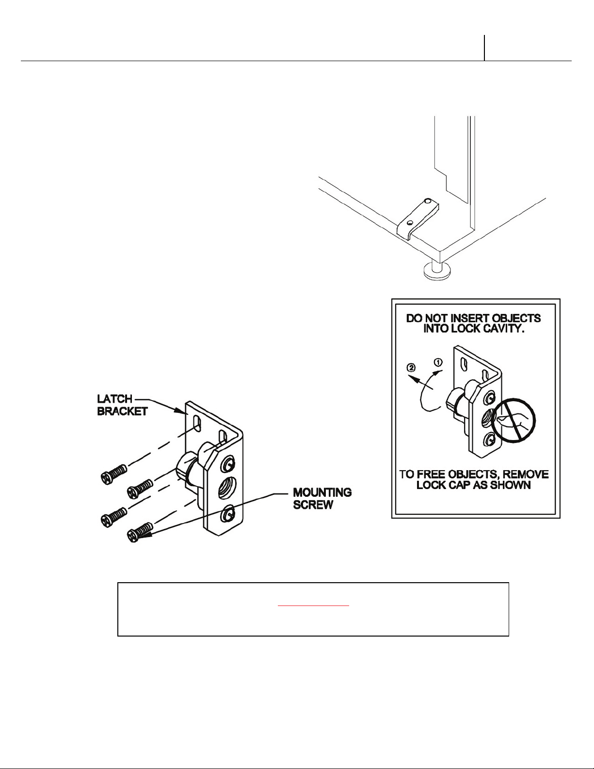
I. Door Support (Figure 2)
The door support is to ensure that the
outer door closes squarely to the cabinet.
Raising the door can also ensure proper
alignment of the door latch.
J. Door Latch Alignment (Figure 3)
After any door adjustment, the floating quicker lock
assembly should align itself automatically. The latch
assembly is adjustable. To adjust, loosen the latch bracket
mounting screws, raise or lower the latch assembly into
position, then tighten the mounting screws.
FIGURE 2
FIGURE 3
NOTE: Refer to the appropriate parts and service manual for detailed instructions,
operating principles, and recommended maintenance intervals and procedures.
WARNING:
KEEP FINGERS AND OTHER OBJECTS OUT OF LOCK CAVITY
V21 Safety | S-6
Page 11
V21 Parts & Service Manual
All V21 Identified Equipment
REV A – 10/2013
P/N: 1230239
SECTION II: ELECTRICAL HAZARDS
GENERAL
SandenVendo America, Inc. vending machines are provided with the appropriate power supply
setting for your area. Some models are equipped with step-down transformers, as required. This
enables the vending machine to operate on different main voltages. Refer to Section I. E. for
information to determine the main power requirements. Refer to the appropriate service manual
for details of step-down transformer operations.
The power sources just mentioned are standard for both household and commercial lighting
and appliances. However, careless or improper handling of electrical circuits can result in injury
or death. Anyone installing, repairing, loading, opening, or otherwise servicing a vending
machine should be alerted to this point. Apply all of the normal precautions observed in
handling electrical circuits, such as:
• Refrigeration servicing to be performed by qualified personnel only.
• Unplug the vendor or move power switch to off position before servicing or clearing
product jams.
• Replace electrical cords if there is any evidence of fraying or other damage.
• Keep all protective covers and ground wires in place.
• Plug equipment into outlets that are properly grounded and polarized (where
applicable), and protected with fuses or circuit breakers.
• All electrical connections must be dry and free of moisture before applying power.
A. Grounding Systems
SandenVendo America, Inc. vending machines are provided with the appropriate service
cord for the power supply in your area. The service cord will connect to the matching
electrical outlet. Always ensure that the outlet to be used is properly grounded before
plugging in the vendor. (See pages S-3 through S-5.)
ALWAYS TEST TO VERIFY PROPER GROUNDING PRIOR
TO INSTALLATION TO REDUCE THE RI S K OF ELE CTRICAL
The electrical grounding system also includes the bonding of all metal components within
the vendor. This involves a system of bonding wires identified by green or green and yellow
marking. The system uses serrated head screws, lock washers, and star washers to ensure the
electrical connection between parts. Maintenance of vending equipment may involve
disassembly. Include the above items when reassembling, even if the vending machine may
appear to function normally without them. Omitting any of these items can compromise a
link in the grounding system. See the appropriate service manual or kit instructions for
components and assembly instructions.
WARNING:
SHOCK AND FIRE
V21
Safety | S-7
Page 12
V21 Parts & Service Manual
All V21 Identified Equipment
REV A – 10/2013
P/N: 1230239
SECTION II: ELECTRICAL HAZARDS (CONTINUED)
WARNING:
B. Servicing with “Power Off”
For maximum safety, unplug the service cord from the wall outlet before opening the vendor
door. This will remove power from the equipment and avoid electrical and mechanical
hazards. Service personnel should remain aware of possible hazards from hot components
even though electrical power is off. See the appropriate sections of this manual for further
information.
C. Servicing with “Power On”
Some service situations may require access with the power on. Power on servicing should be
performed only by fully-qualified service technicians. Particular caution is required in
servicing assemblies that combine electrical power and mechanical movement. Sudden
movement (to escape mechanical action) can result in contact with live circuits and vice
versa. It is therefore doubly important to maintain maximum clearances from both moving
parts and live circuits when servicing.
Power to lighting and refrigeration system is shut off automatically by the electronic
controller when the outer door is opened.
NOTE: For power-on servicing of the vendor’s lighting system, turn lighting power on by
accessing the Lights test function of the electronic controller (see programming on inner door).
For power-on servicing of the vendor’s refrigeration system, turn refrigeration power on by
accessing the Compressor test function of the electronic controller (see programming on inner
door).
“POWER ON” SERVICING SHOULD BE ACCOMPLISHED ONLY
BY FULLY-TRAINED PERSONNEL. SUCH SERVICE BY
UNQUALIFIED INDIVIDUALS CAN BE DANGEROUS.
V21 Safety | S-8
Page 13

V21 Parts & Service Manual
All V21 Identified Equipment
REV A – 10/2013
P/N: 1230239
SECTION III: MECHANICAL HAZARDS
WARNING:
A. Servicing of Moving Parts and Assemblies
When servicing assemblies involving moving parts, use extreme caution!! Keep fingers,
hands, loose clothing, hair, tools, or any foreign material clear of entrapment.
As noted before under the electrical hazards section, Power On servicing should only be
performed by qualified personnel. Refer to and heed the warnings noted in the electrical
hazards section. These warnings refer to the potential hazards associated with electrical
power and moving parts. Always maintain maximum clearances from electrical and moving
parts.
Always install protective covers and guards when reassembling equipment.
THIS VENDING MACHINE INCLUDES MECHANICAL EQUIPMENT
WHICH CAN BE HAZARDOUS IF IMPROPERLY HANDLED OR
SERVICED. USE CAUTION AND CONSULT THE SandenVendo
America, Inc. SAFETY MANUAL AND SandenVendo America, Inc.
SERVICE MANUAL FOR ADDITIONAL SAFETY INFORMATION.
V21 Safety | S-9
Page 14
V21 Parts & Service Manual
All V21 Identified Equipment
REV A – 10/2013
P/N: 1230239
SECTION IV: REFRIGERATION HAZARDS
WARNING:
AND BODY WHEN WORKING NEAR THE REFRIGERATION SYSTEM
GENERAL
Refrigeration systems involve both electrical power and mechanical action. These systems may
present any of the potential dangers shown in the sections on electrical and mechanical hazards
contained in this manual. See Sections II and III for further information.
A. Compressed Refrigerant
Refrigeration systems involve the compression and evaporation of gases. The pressures
contained represent a potential hazard if suddenly released in confined areas. Caution is
required when performing maintenance tests or repairs. All testing of sealed refrigeration
systems must be done by trained personnel who are familiar with the systems and
pressures involved.
B. Physical Protection
The accidental release of refrigerant gases can result in physical injuries. Always wear
protective glasses and protect your hands, face, and body when working near the
refrigeration system.
ALWAYS WEAR EYE PROTECTION AND PROTECT YOUR HANDS, FACE,
SECTION V: TEMPERATURE HAZARDS
GENERAL
Maintenance personnel should be alerted to the potential hazards from hot metal surfaces. High
temperatures may be present throughout the refrigeration system even though electrical power
has been removed.
V21 Safety | S-10
Page 15

V21 Parts & Service Manual
All V21 Identified Equipment
REV A – 10/2013
P/N: 1230239
SECTION VI: SUBSTITUTIONS AND MODIFICATIONS
WARNING:
REPLACED ONLY WITH FACTORY-AUTHORIZED PARTS.
GENERAL
Unauthorized changes or the substitution of unauthorized parts can compromise the equipment
designs. This can result in unsafe conditions for either the service personnel or the equipment
users. Always refer to the appropriate parts and service manual for replacement parts and
maintenance instructions. If questions arise, contact the Technical Services Department of the
SandenVendo America, Inc. office in your area.
When servicing the vending machine, always reassemble all components to their original
location and position. Maintain the correct routing for tubing, electrical wiring, etc. Replace all
clamps, brackets, and guides to their original locations. Replace all tubing, sleeving, insulating
material, and protective covers to their original condition.
SandenVendo America, Inc. EQUIPMENT HAS BEEN PROVIDED WITH
APPROPRIATE PROTECTIVE DEVICES TO PROTECT AGAINST THE
MODIFICATION, OR BYPASSING OF SUCH PROTECTIVE DEVICES CAN
CREATE DANGEROUS CONDITIONS. PROTECTIVE CIRCUITS SHOULD
POSSIBILITY OF OVERHEATING AND FIRE AS A RESULT OF
EQUIPMENT OR COMPONENT FAILURES. SUBSTITUTION,
NEVER BE BYPASSED, AND FAILED PROTECTIVE DEVICES MUST BE
A. Service Cord Replacement
SandenVendo America, Inc. vending machines are furnished with unique power supply
cords. If replacement becomes necessary, consult the appropriate parts and service
manual and order the correct replacement cord for the model of vending machine in
question. Do not use substitute replacement cords. Only authorized service personnel
with appropriate training should replace the vending machine service cord. If a question
should arise concerning which service cord to order, contact the Technical Services
Department of the SandenVendo America, Inc. office in your area.
V21 Safety | S-11
Page 16

V21 Parts & Service Manual
All V21 Identified Equipment
REV A – 10/2013
P/N: 1230239
SECTION VII: SUBSTITUTIONS AND MODIFICATIONS (CONTINUED)
WARNING:
The wires in the main leads are colored in accordance with the following code:
THIS APPLIANCE MUST BE EARTHED. IMPORTANT!
110v/120v 220v/240v
Green Green and Yellow ............................. Earth
White Blue ................................................... Neutral
Black Brown ................................................ Live
V21 Safety | S-12
Page 17
V21 Parts & Service Manual
All V21 Identified Equipment
REV A – 10/2013
P/N: 1230239
SECTION VIII: CONSUMER SAFETY WARNING
WARNING:
THE FOLLOWING DECAL SHOULD BE PLACED IN A POSITION ON THE
VENDOR CAN BE OVERTURNED IF SUFFICIENT FORCE IS APPLIED
GENERAL
There have been incidents, including fatalities, when vending machines have been vandalized by
being pulled over in an attempt to obtain free product or money. To warn of the danger
involved in tipping, shaking, or rocking the vending machine, a decal has been designed to be
affixed to vending machines. (One such decal is applied on the vending machine.) SandenVendo
America, Inc. will supply sufficient decals to be placed on all machines, on request. If you have
any questions, contact the Technical Services Department of the SandenVendo America, Inc.
office in your area.
AND MAY RESULT IN SERIOUS INJURY OR DEATH.
VENDOR CONTROL PANEL AT EYE LEVEL
V21 Safety | S-13
Page 18
V21 Parts & Service Manual
All V21 Identified Equipment
REV A – 10/2013
P/N: 1230239
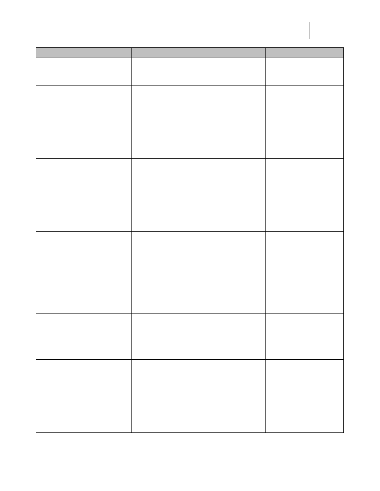
AREA
ADDRESS
PHONE NUMBERS
SandenVendo America, Inc.
Dallas, TX 75238-1335 U.S.A.
Sanden International Corporation
Tokyo 110, Japan
Vendo GMBH
Germany
Australia
Sanden International (Singapore) Pte., Ltd.
The Republic of Singapore
Sanden International Taiwan Corp.
Taiwan, ROC
Vendo UK Ltd.
Great Britain
Vendo Italy S.p.A.
Italy
Vendo Iberia, S.A.
08940 Cornella, (Barcelona), Spain
United States, Canada
Japan
Europe, Mid-East, Africa,
Mid-Asia
Australia, New Zealand
Singapore, Hong Kong,
Indonesia, Philippines, India
Taiwan
10710 Sanden Drive
31-7 Taito 1-Chome
Taito-ku
Spangerstr. 22, P.O. Box 130940
40599 Dusseldorf
Sanden International Pty. Ltd.
54 Allingham St., Condell Park
N.S.W. 2200
Sanden House, 25, Ang Mo Kio St. 65
Singapore 569062
No, 21-6, Sec 1
Tun Hwa S. Rd., Taipei, Taiwan
Tel: (800) 344-7216
Fax: (800) 541-5684
Tel: (81) 3-3835-1321
Fax: (81) 3-3833-7096
Tel: (49) 211-74-039-0
Fax: (49) 211-7488541
Tel: 61-2-9791-0999
Fax: 61-2-9791-9029
Tel: 65-482-5500
Fax: 65-482-1697
Tel: 886-2-570-6106
Fax: 886-2-577-1959
Belgium
England
Italy
Spain
N.V. Vendo Benelux, S.A.
Industrial Research Park N.O.H.
13 Font St. Landry
1120 Brussels
Belgium
Vendo House
Kingsclere Road
Basingstoke, Hants RG21, 5GU
Casella Postale 9
1-15033 Casale Monferrato
C/ Sant Ferran No. 92
Poligono Industrial la Almeda, Sector P-1
Safety | S-14
V21
Tel: 32-2-268-2595
Fax: 32-2-268-2862
Tel: 44-1256-479309
Fax: 44-1256-844469
Tel: 39-142-335111
Fax: 39-142-5623-48
Tel: 343-474-1555
Fax: 343-474-1842
Page 19
V21 Parts & Service Manual
All V21 Identified Equipment
REV A – 10/2013
P/N: 1230239
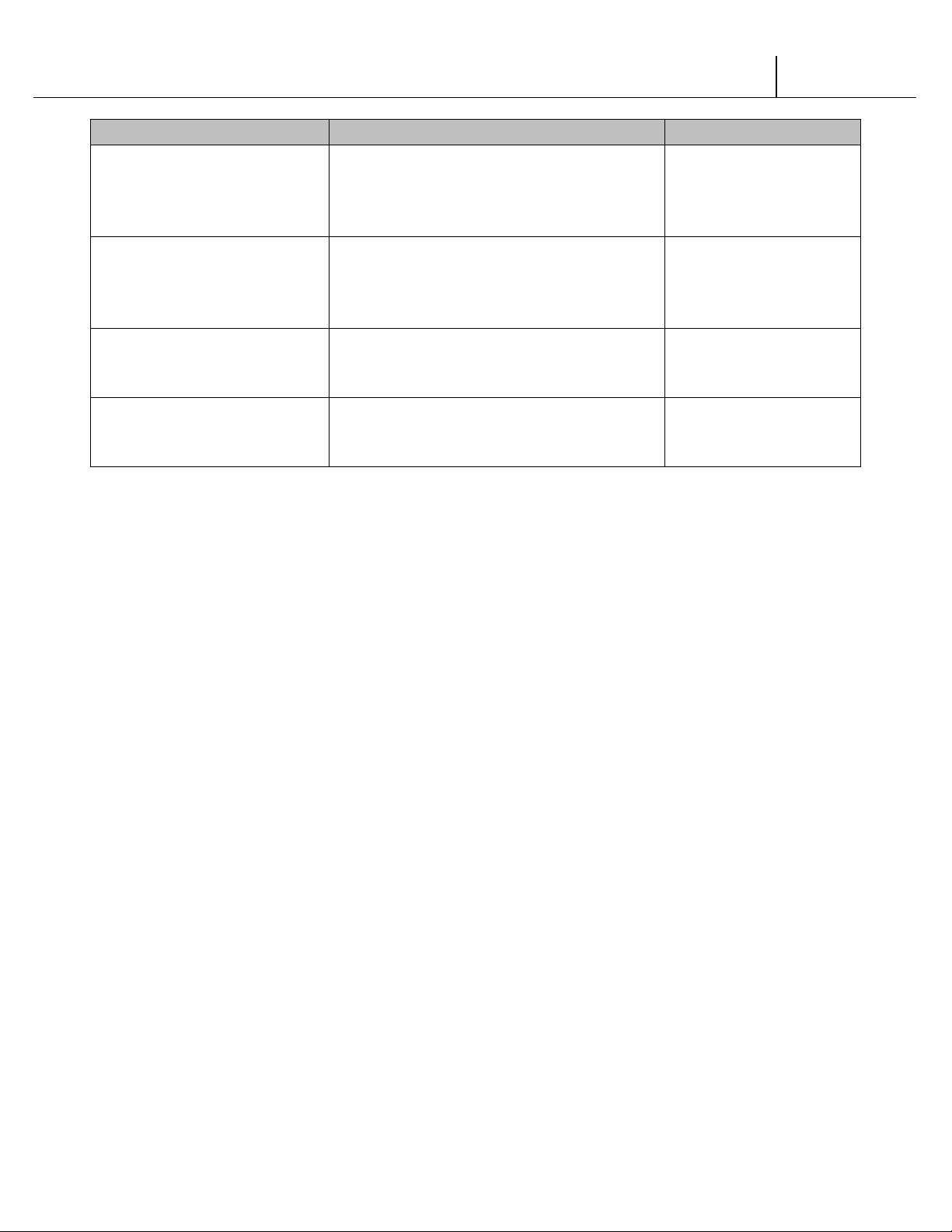
AREA
ADDRESS
PHONE NUMBERS
Vendo de Mexico
IMI Cornelius de Mexico, S.A. de C.V.
SandenVendo America, Inc.
Dallas, TX 75238-1335 U.S.A.
Dallas, TX 75238-1335 U.S.A.
Mexico
Mexico
Central America
South America
Carreta Mexico - Tequisquiapan Km 3.2
San Juan del Rio, Queretaro
C.P. 76800
Manual Dublan No. 35
Col. Tacubaya, Deleg. Miguel Hidalgo
C.P. 11870 Mexico
10710 Sanden Drive
SandenVendo America, Inc.
10710 Sanden Drive
Tel: (52) 427 2718096
Fax: (52) 427 2718077
Tel: (52 55) 5272-7904
Fax: (52 55) 5273-5949
Tel: (214) 765-9066
Fax: (214) 221-7010
Tel: (214) 765-9066
Fax: (214) 221-7010
V21
Safety | S-15
Page 20

V21 Parts & Service Manual
All V21 Identified Equipment
REV A – 10/2013
P/N: 1230247
GENERAL INFORMATION
V21 General Information | G-1
Page 21
V21 Parts & Service Manual
All V21 Identified Equipment
REV A – 10/2013
P/N: 1230247
GENERAL INFORMATION
This manual contains programming, operation, and complete parts and electrical wiring
diagrams.
The V21 controller is a microprocessor which will permit pricing per selection from 0.00 to 99.99.
This machine also has space-to-sales programming as well as energy savings modes.
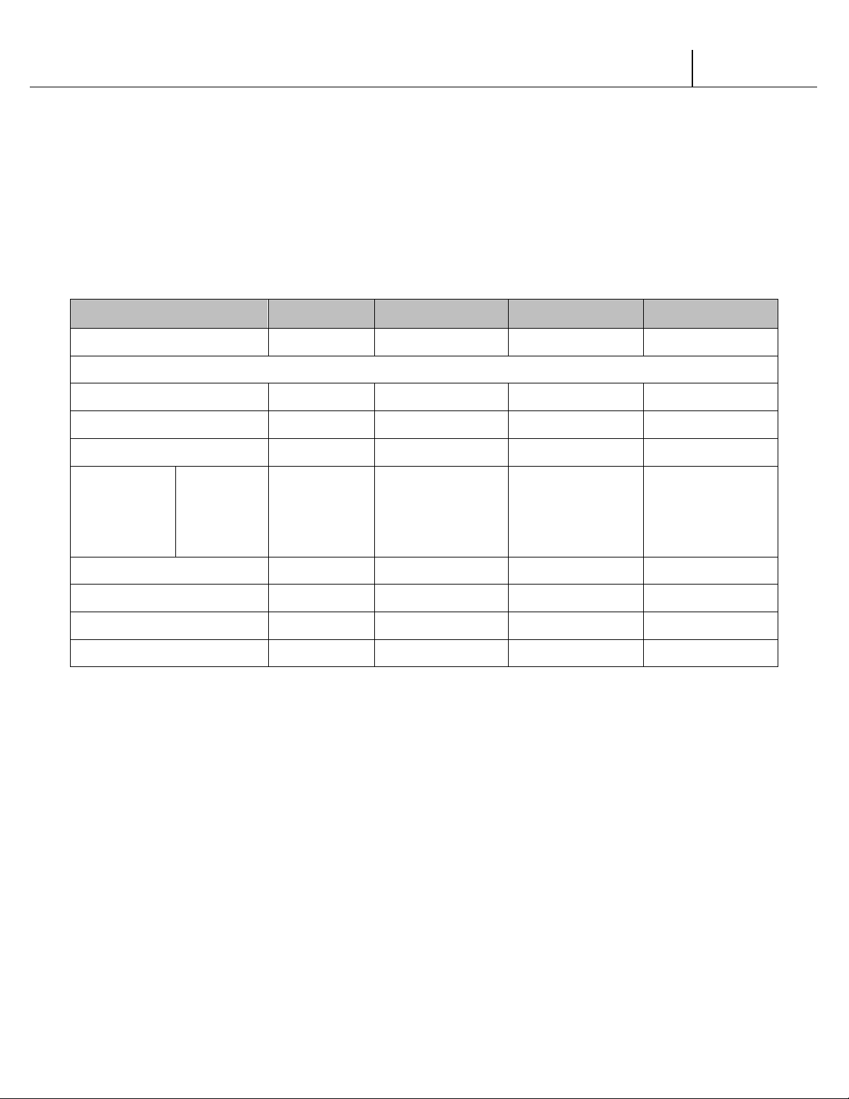
MODEL V21 521 V21 621 V21 721 V21 821
MAXIMUM SELECTIONS 7 8 10 10
DIMENSIONS (HEIGHT X WIDTH X DEPTH)*
CURVED DOOR 61” x 29” x 24” N/A 72” X 39.5” X 35” 79” X 39.5” X 35”
FLAT DOOR N/A 72” X 32.5” X 34.5” 72” X 39.5” X 32.5” N/A
SINGLE COLUMNS 7 8 10 10
12oz.
CAPACITY PER
COLUMN
SHIPPING WEIGHT* 365 lbs. 640 lbs. 685 lbs. 750 lbs.
OPERATION VOLTAGE 115V 60Hz 115V 60Hz 115V 60Hz 115V 60Hz
AMP. RATING 4 8 8 8
REFRIGERATION VOLTAGE 115V 60Hz 115V 60Hz 115V 60Hz 115V 60Hz
CAN***
16oz. GLASS
20oz. PET **
26
13
13
68
28
30
68
28
30
80
34
36
*Dimensions and shipping weight will vary slightly due to manufacturing tolerances, shipping
boards and whether or not coinage is installed.
** 20 oz. PET capacity may vary based on the shape and size of the bottle.
***12 oz. can capacities are listed using a 4-deep set up.
V21 General Information | G-2
Page 22

V21 Parts & Service Manual
All V21 Identified Equipment
REV A – 10/2013
P/N: 1230247
INITIAL SET-UP
A. UNPACKING
Remove all plastic film, cardboard and tape from the outside of the vendor. Loosen any
shipping devices used to secure interior parts during shipment (backspacer, shims or
spacers).
To remove shipping boards from base, raise vendor on a well-stabilized lifting device.
Remove the leveling bolts which hold the boards in place and remove the boards. Replace
bolts to equal heights in the threaded holes. Another method to remove shipping boards is
to split the boards apart. Using a pinch bar or a heavy screwdriver and hammer, insert tool
into the slots and force the boards apart. The leveling legs shall not raise the vendor
more than 1 1/8 inch above the ground.
B. POSITIONING
IMPORTANT: PLACE THE VENDOR IN DESIRED LOCATION AT LEAST THREE TO FOUR
INCHES (7.6CM TO 10.2CM) AWAY FROM ANY REAR OBSTRUCTION. This is for proper
air flow through the refrigeration compartment. The refrigeration system requires rear to
front air circulation for proper operation.
C. POWER SUPPLY CONNECTION
CAUTION: DO NOT USE AN EXTENSION CORD!
The vendor’s power requirements will vary depending upon the country it was purchased for. To
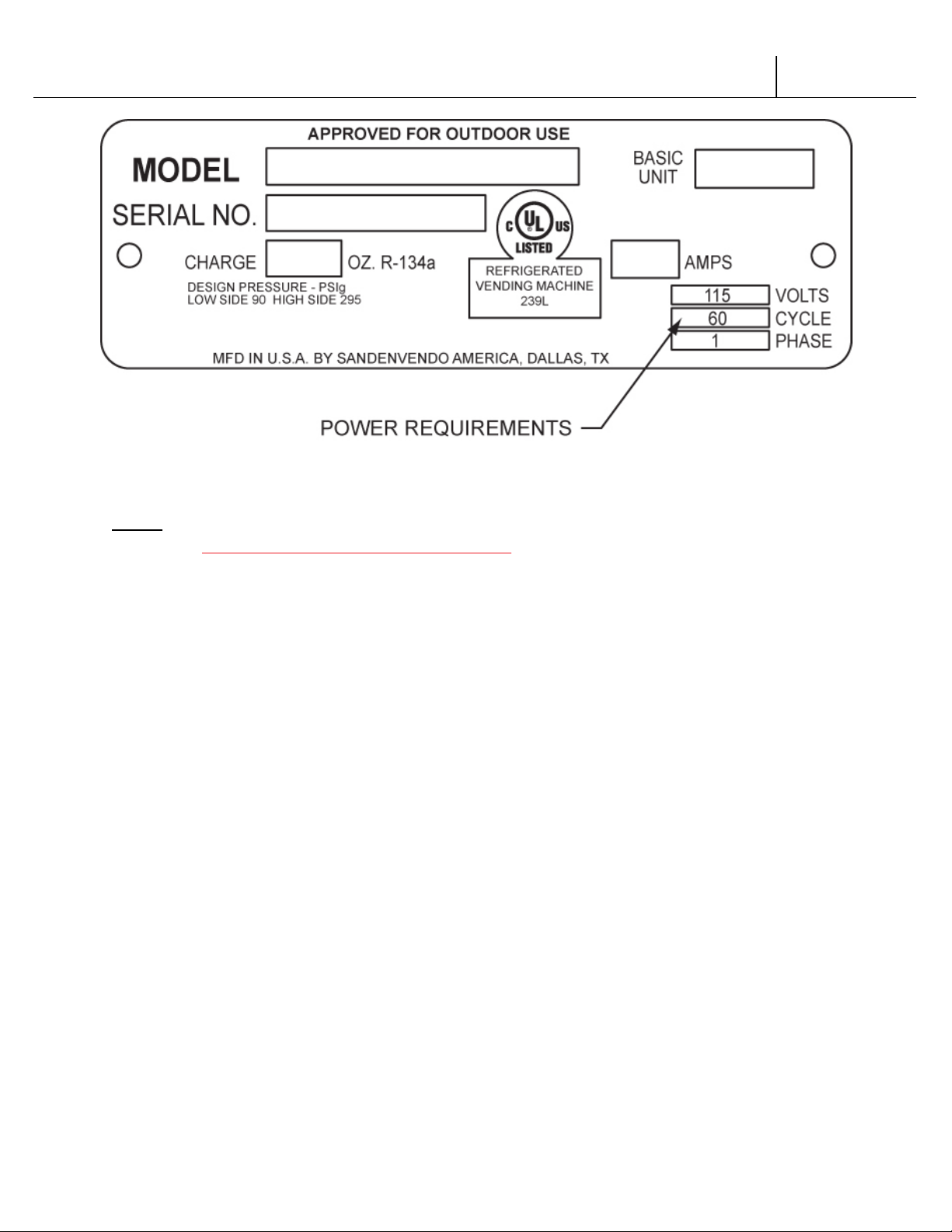
verify the power requirements of the vendor, check the serial plate located on the hinged side of
the outer door (see Figure 4 on page G-4). The power requirements are listed on the serial plate.
To ensure safe operation of the vendor, the vendor’s power supply must be a properly
grounded and polarized outlet. Before plugging the vendor into the outlet, test the outlet to
confirm it will meet the vendor’s power requirements. If the power supply of the outlet is
different from the power requirements of the vendor, a transformer may be necessary.
If the power requirements are not properly met, contact a licensed electrician and have the
necessary correction made.
Should you require additional information, contact the Technical Services Department of the
SandenVendo America, Inc. office in your area.
V21 General Information | G-3
Page 23
V21 Parts & Service Manual
All V21 Identified Equipment
REV A – 10/2013
P/N: 1230247
FIGURE 1
NOTE: The Model number of the vending machine is located on the top, left hand corner of the
serial plate. Do Not use the “BASIC UNIT” number. The BASIC UNIT number is the cabinet size,
which is used on a number of different machines. A typical model number could read
“721TDD00029”. The 721 is the model number, TDD represents the product line of the vendor, and
the remaining digits tell what options are included.
V21 General Information | G-4
Page 24
V21 Parts & Service Manual
All V21 Identified Equipment
REV A – 10/2013
P/N: 1230247
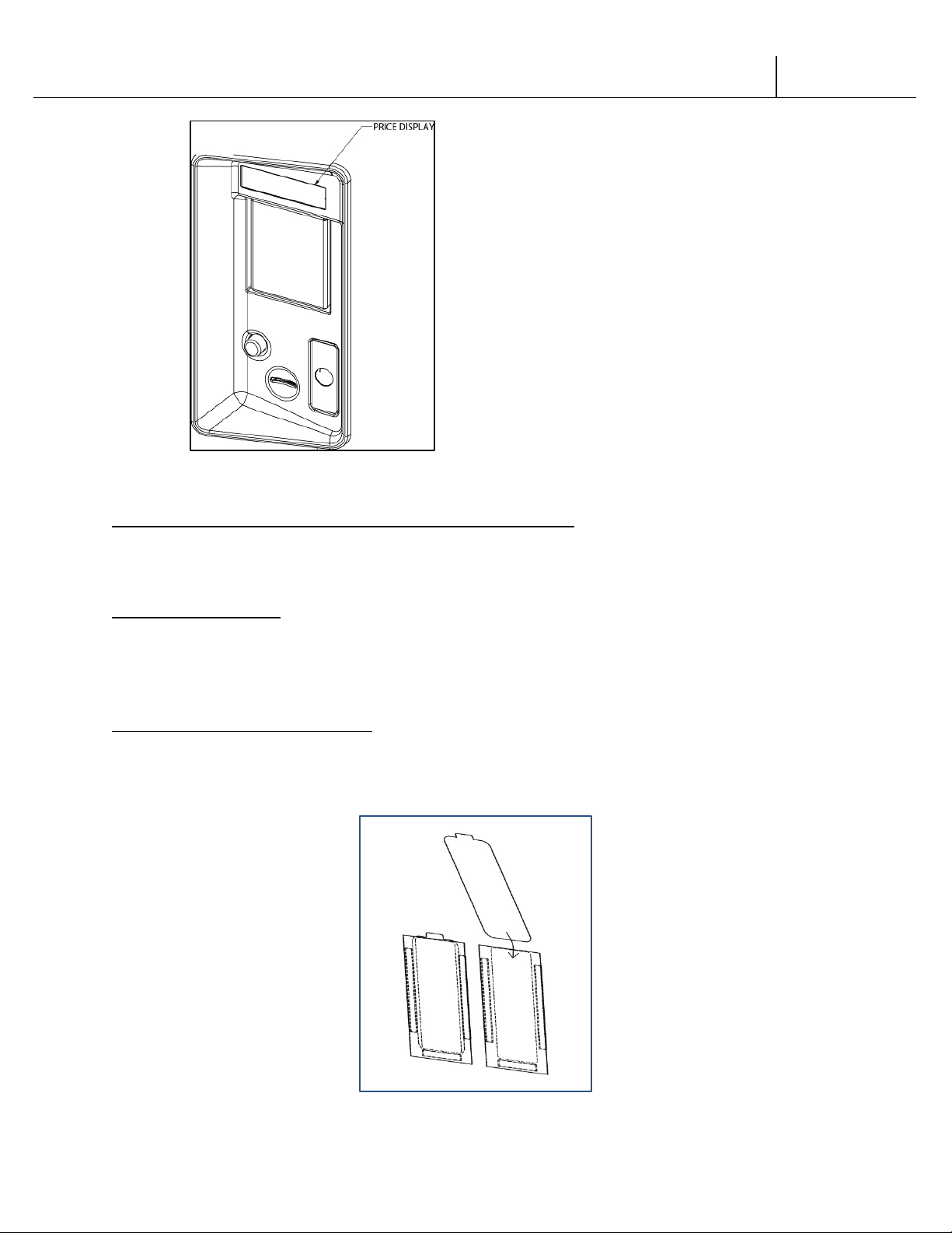
Figure 2
LABEL INSTALLATION CHAMELEON
COIN INSTRUCTION LABEL & PRICE LABEL APPLICATION:
Apply labels to a clean and dry surface. Peel backing from label and apply with firm, even
pressure.
INSTRUCTION LABEL
(Refer to Figure 2 for the following information.)
The coin insert shows the validator opening built into the coin insert. Apply instruction label to
area shown (as needed by the vendor).
FLAVOR LABELS INSTALLATION:
As shown in Figure 3, insert flavor labels to the top of selection window. Rear views of windows
and buttons are shown in Figure 3. Arrows point the direction to insert labels.
Selection window and selection button labels identify product contained in columns.
Figure 3
V21 General Information | G-5
Page 25
V21 Parts & Service Manual
All V21 Identified Equipment
REV A – 10/2013
P/N: 1230247
LABEL INSTALLATION TRADE
COIN INSTRUCTION LABEL & PRICE LABEL APPLICATION:
Apply labels to a clean and dry surface. Peel backing from label and apply with firm, even
pressure.
INSTRUCTION LABEL
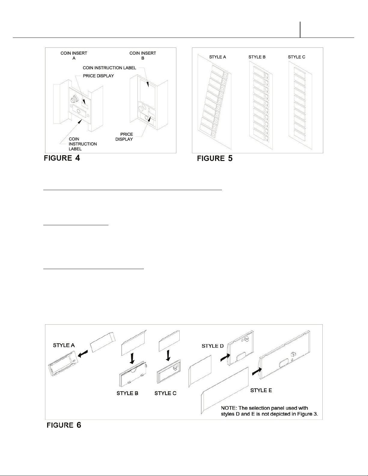
(Refer to Figure 4 for the following information.)
Coin insert “A” has a separate validator opening, and insert “B” shows the validator opening built
into the coin insert. Apply instruction label to area shown (as needed by the vendor).
FLAVOR LABELS INSTALLATION:
In Figure 6, corresponding styles are indicated by A, B, C, D, or E notations. Insert flavor labels to
the side or top of selection window or button depending on the style. See Figure 5 for selection
style. Rear views of windows and buttons are shown in Figure 6. Arrows point the direction to
insert labels.
Selection window and selection button labels identify product contained in columns.
V21 General Information | G-6
Page 26
V21 Parts & Service Manual
All V21 Identified Equipment
REV A – 10/2013
P/N: 1230247
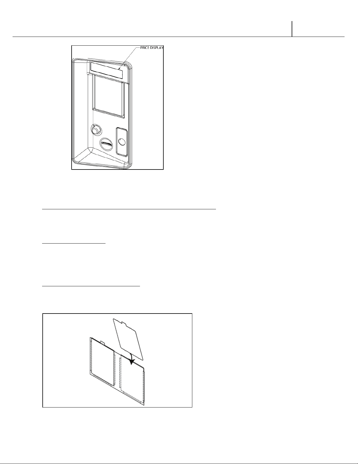
Figure 7
LABEL INSTALLATION HV3
COIN INSTRUCTION LABEL & PRICE LABEL APPLICATION:
Apply labels to a clean and dry surface. Peel backing from label and apply with firm, even
pressure.
INSTRUCTION LABEL
(Refer to Figure 7 for the following information.)
The coin insert shows the validator opening built into the coin insert. Apply instruction label to
area shown (as needed by the vendor).
FLAVOR LABELS INSTALLATION:
As shown in Figure 8, insert flavor labels to the top of selection window. Arrows point the
direction to insert labels. Selection window labels identify product contained in columns.
Figure 8
V21 General Information | G-7
Page 27
V21 Parts & Service Manual
All V21 Identified Equipment
REV A – 10/2013
P/N: 1230247
LABEL INSTALLATION HVV
A. FLAVOR LABELS
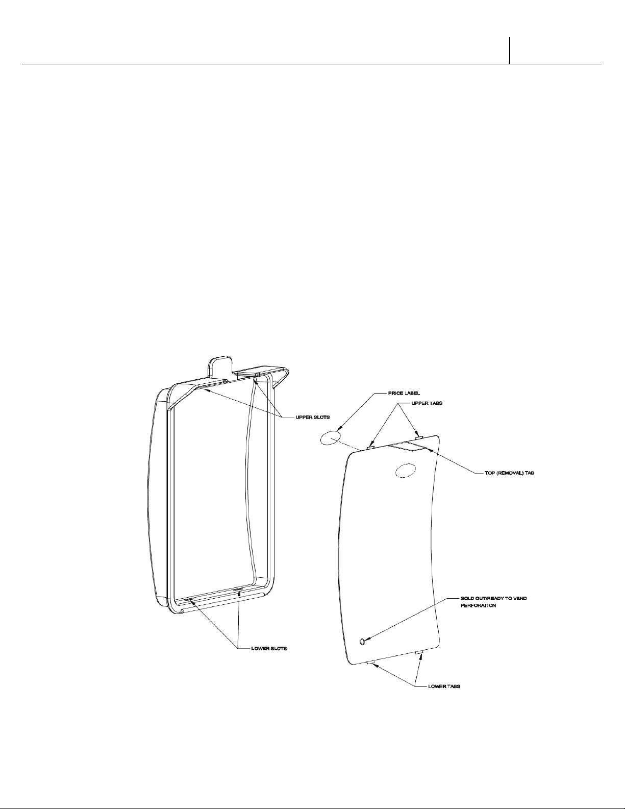
Before installing flavor labels, bend the top (removal) tab down. To install flavor labels, insert
the two small tabs on the bottom edge of the label into the slots in the selection button.
Press the label in near the two upper tabs until the tabs snap into the slots in the upper wall
of the selection button. (See Figure 9)
Note: if vendor is equipped with optional sold out/ready to vend indicators, then
remove the perforated slug from the lower corner of the flavor label to allow the LED
dome to show through. (See Figure 9)
B. PRICE LABELS
Individual price labels can be applied to the flavor labels. The price labels are located in the
upper right corner of the flavor labels in the area indicated by a dashed oval.
Figure 9
V21 General Information | G-8
Page 28
V21 Parts & Service Manual
All V21 Identified Equipment
REV A – 10/2013
P/N: 1230247
ALIGNMENT CHECKS
REFRIGERATION AREA CHECK:
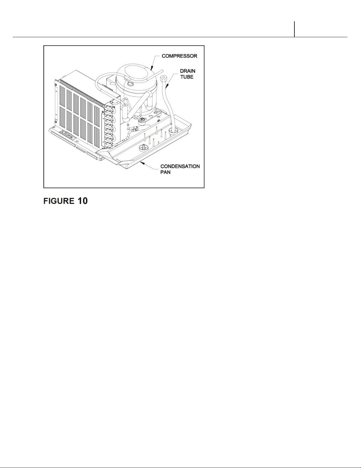
Check the position of the condensation pan (see Figure 10). The correct position of the pan is on
the right hand side of the vendor with the ramp of the pan just outside the right hand air dam.
Be sure the drain tube is attached to the pan and is free of kinks. A water trap is installed into
the condensation pan and will prevent warm, moist air from reaching the evaporator area.
LOADING INSTRUCTIONS
BASIC LOAD SET-UP (see Figure 11 on next page):
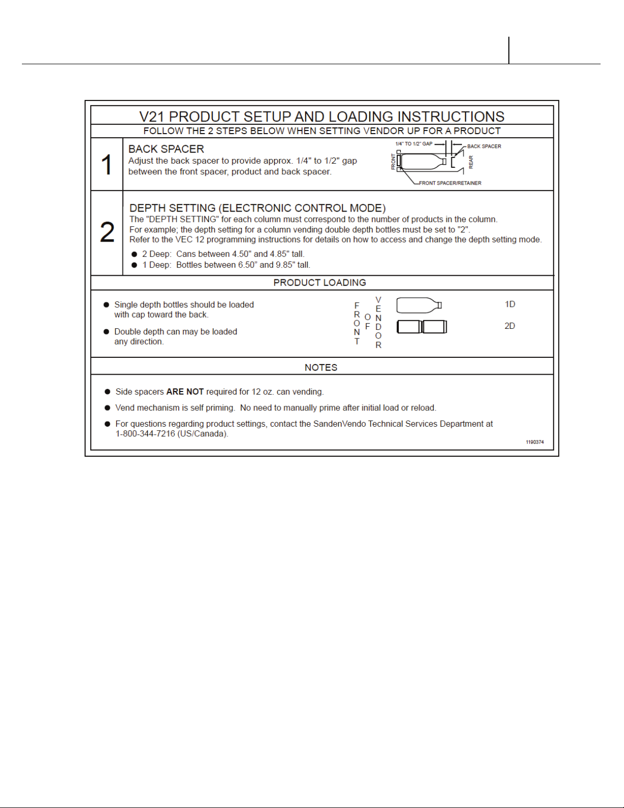
The V21 machine is capable of vending a variety of products. For specific information, refer to
the product set-up label on the machine inner door or contact the Technical Services
Department of the SandenVendo America, Inc. office in your area.
Load product evenly. Product is to be loaded differently depending on the type of product
being vended. Use the directions in Figure 6 in the PRODUCT LOADING section to determine
how to load a specific product.
To maintain the integrity of the stack, never move a vending machine when it is loaded.
V21 General Information | G-9
Page 29

V21 Parts & Service Manual
All V21 Identified Equipment
REV A – 10/2013
P/N: 1230247
V21 General Information | G-10
Page 30
V21 Parts & Service Manual
All V21 Identified Equipment
REV A – 10/2013
P/N: 1230247
FOR V21 MODEL 521
V21 General Information | G-11
Page 31

V21 Parts & Service Manual
All V21 Identified Equipment
REV A – 10/2013
P/N: 1230247
VEND MECHANISM PARTS DESCRIPTION
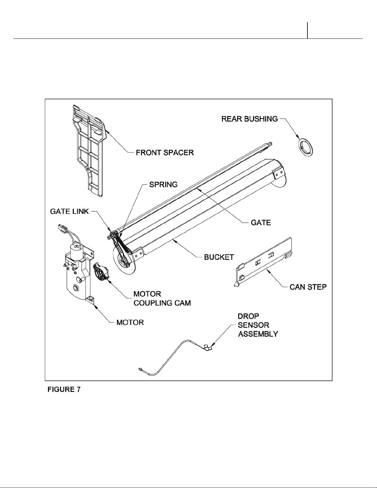
The parts listed below are part of the vend motor mechanism (refer to Figure 7 on page G-10).
One mechanism is required per column, except the drop sensor assembly, which is one
assembly per machine. The parts are interchangeable. Setting will differ between single, double,
triple, and quadruple depth.
VEND MOTOR ASSEMBLY:
The motor is attached to the mech plate by two screws.
VEND BUCKET:
The vend bucket holds the product(s) in a “ready to vend” position at the base of each column.
MOTOR COUPLING CAM:
The coupling cam couples the motor to the bucket. It is located behind the motor, on the motor
shaft. It is also a means to provide feedback to the controller to determine when the motor has
reached maximum clockwise and counterclockwise positions.
GATE:
The gate holds product above the vend bucket.
GATE LINK:
The rotation of the coupling cam moves the gate link. This opens the gate, allowing one layer of
product to drop into the bucket.
CAN STEP (NOT APPLICABLE ON 521 MODELS):
The can step is located at the bottom of the stack partition. It is pulled forward when vending
cans and is moved back for bottle vending.
REAR BUSHING:
The rear bushing provides a low friction pivot for the rear of the bucket.
FRONT SPACER:
The front spacer helps to guide product into the bucket.
DROP SENSOR ASSEMBLY:
The drop sensor assembly is located below the delivery chute. When a product is vended, the
drop sensor senses the impact, and cancels the credit.
FRONT BUSHING (ONLY APPLICABLE ON 521 MODELS):
The front Bushing provides a low friction pivot for the front of the bucket.
V21 General Information | G-12
Page 32
V21 Parts & Service Manual
All V21 Identified Equipment
REV A – 10/2013
P/N: 1230247
V21 General Information | G-13
Page 33

V21 Parts & Service Manual
All V21 Identified Equipment
REV A – 10/2013
P/N: 1230247
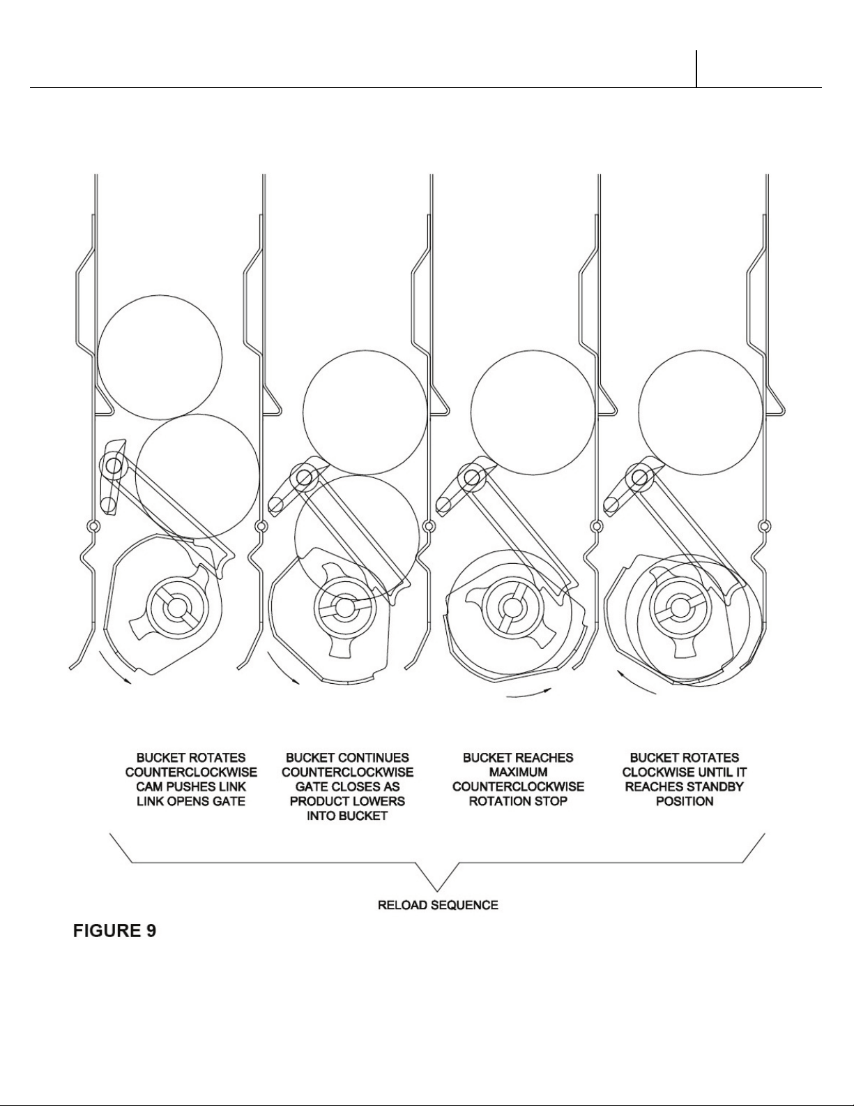
VEND CYCLE
Several operations take place during the vend cycle: When a selection is made, the coupler and
bucket rotate, product is dispensed and the bucket is then reloaded. The sequence of these
operations changes slightly when the column’s depth setting is changed. With the single depth
setting, one purchase is made and the bucket is reloaded. With the double depth setting, two
purchases are made before the bucket is reloaded. With the triple depth setting, three purchases
are made before the bucket is reloaded. With the quadruple depth setting, four purchases are
made before the bucket is reloaded. (See Figures 8 & 9)
V21 General Information | G-14
Page 34
V21 Parts & Service Manual
All V21 Identified Equipment
REV A – 10/2013
P/N: 1230247
V21 General Information | G-15
Page 35

V21 Parts & Service Manual
All V21 Identified Equipment
REV A – 10/2013
P/N: 1230255
HV3 / CHAMELEON
PROGRAMMING SECTION
12.4 PROGRAMMING
V21 12.4 Programming HV3 / CHAMELEON | P1-1
Page 36

V21 Parts & Service Manual
All V21 Identified Equipment
REV A – 10/2013
P/N: 1230255
VEC 12.4 PROGRAMMING OPERATIONS
NOTE: Some units may contain a European font display, in which case the “°” symbol will
be replaced by the “ß” symbol. Example: 72°F will be 72 ß F.
The VEC 12.4 Controller uses a 4-button programming system:
Programming Buttons: # 1 – Escape/Exit
# 2 – Decrease/Scroll Down
# 3 – Increase/Scroll Up
# 4 – Enter and/or Save
To access Mode functions, open the door. Locate the Mode Button on the Main Control Board
and press until Diagnostics appears. Use selection button 2 or 3 to navigate through the modes.
The Modes are as follows:
Diagnostics
Coin Payout
Tube Fill
Test Mode
Cash Data
Sales Data
Set Price
Set Depth
Configuration
Space to Sales
Set Program Password
Set Language
Set Clock *
Lighting *
Refrigeration **
Sales Block 1 *
Sales Block 2 *
Discount *
Override **
Return
* These modes will only appear when the “Timing Feature” in Configuration is turned On.
** Limited options appear in this mode depending on whether the Timing Feature in
Configuration is On/Off.
V21 12.4 Programming HV3 / CHAMELEON | P1-2
Page 37

V21 Parts & Service Manual
All V21 Identified Equipment
REV A – 10/2013
P/N: 1230255
Diagnostics:
See inner door of vendor or Troubleshooting section for errors and how to clear them.
Coin Payout:
Coin Payout Mode allows the operator to ‘test’ for proper operation of the changer tubes.
1. Press Button 4 to enter into “Coin Payout” mode.
2. Press Button 2 or 3 to scroll to desired denomination.
3. Press Button 4 to dispense displayed denomination.
4. Press Button 1 to exit mode.
Tube Fill:
Allows you to fill coin tubes via the external coin insert. This is the recommended way to fill the
coin tubes because the control board is able to keep an accurate count of the coins.
1. Press Button 4 to enter into “Tube Fill” mode.
2. Insert coins into coin insert slot and the controller will “count” the number of coins going
into the coin mechanism.
Test Mode:
Allows you to test vend a column, jog a column, test selection switches, display, refrigeration
system, lights, and heater.
Vending a Column:
1. At “Test Mode”, press Button 4. Display will read –“Test Mode – Vending”
2. Press Button 4 to enter – the display will read “Column 1”.
3. Press Button 2 or Button 3 to scroll to the desired column.
4. Press Button 4 to vend.
a. If motor vends OK, DISPLAY will read “Test Mode - Vending Motor OK”
b. If motor does not test OK on one of the following messages will appear:
- “Test Mode - Vending Fail - Column Jam”
- “Test Mode - Vending Fail - No Connection”
- “Test Mode - Vending Fail - High Current”
Jogging a Column:
Allows you to test the column in forward and reverse direction.
1. At “Test Mode” press Button 4.
2. Press Button 2 or 3 to scrollto “Test Mode - Jog.”
3. Press Button 4 and display will read “Column 1.”
4. Press Button 2 or 3 to scroll to desired column.
5. Press Button 4 to enter into column and display will read “Column X Forward” with X
being the desired column.
6. Press Button 2 or 3 to scroll between “Forward” or “Reverse.”
7. Press Button 4 to move/jog the motor in the desired position.
8. Press Button 1 to exit this mode.
12.4 Programming HV3 / CHAMELEON | P1-3
V21
Page 38

V21 Parts & Service Manual
All V21 Identified Equipment
REV A – 10/2013
P/N: 1230255
Test Mode Display:
Allows you to verify that all of the characters on the display illuminate.
1. At “Test Mode” press Button 4.
2. Press Button 2 or 3 to scroll until display reads “Test Mode - Display.”
3. Press Button 4.
4. All of the characters on the display should illuminate.
5. Press Button 4 to exit.
Selection Switch Testing:
Allows you to test the selection switches.
1. At “Test Mode” press Button 4.
2. Press Button 2 or 3 to scroll to “Test Mode Switches”.
3. Press Button 4
4. Press desired selection switch to be tested.
5. To exit press Button 1 and hold for 3 seconds.
Test Mode Relays:
Allows you to test the compressor, evaporator fan, lights and heater.
1. When “Test Mode” is displayed press Button 4.
2. Press Button 2 or 3 to scroll until display reads “Test Mode - Relays”
3. Press Button 4.
4. Press Button 2 or 3 to advance through sub-modes.
5. Press Button 4 at “Compressor” prompt to test compressor.
6. Press Button 4 at “Light” prompt to test lighting system.
7. Press Button 4 at “Fan” prompt to test evaporator fan.
8. Press Button 4 at “Heater” prompt to test optional heater.
9. Press Button 1 to exit sub-modes.
Cash Data:
This Mode allows you to retrieve historical information regarding the money accepted by the
vendor. To clear the individual selection cash data, you must have the MIS Auto Reset in the
“Configuration” mode turned to ON.
1. When “Cash Data” is displayed press Button 4. The non-resettable historical data is
displayed.
2. Press Button 2 or 3 to display resettable individual selections.
3. To reset historical data, make sure the MIS Auto Reset is turned ON in the configuration
mode.
4. Press Button 1 to exit mode.
V21 12.4 Programming HV3 / CHAMELEON | P1-4
Page 39

V21 Parts & Service Manual
All V21 Identified Equipment
REV A – 10/2013
P/N: 1230255
Sales Data:
This Mode allows you to retrieve historical information regarding the number of units sold by
vendor. To clear the individual selection sales data, you must have the MIS Auto Reset in the
“Configuration” mode turned ON.
1. When “Sales Data” is displayed, press Button 4. The non re-settable historical data is
displayed.
2. Press Button 2 or 3 to display resettable individual selections.
3. To reset historical data, make sure the MIS Auto Reset is turned ON in the configuration
mode.
4. Press Button 1 to exit mode.
Discount Counter:
This mode allows you to view historical sales and cash data in the vendor that have been vended
at a discounted price. This mode is populated only if there have been a discounted sales.
1. When “Discount Counter” is displayed, press Button 4 to view total discount vend sales.
2. Press Button 2 or 3 to display discount counter for individual selections.
3. Press Button 1 to exit mode.
Free Counter:
This mode allows you to view historical sales in the vendor at a free vend mode. This mode is
visible only if there has been a sales on a free vend mode.
1. When “Free Counter” is displayed, press Button 4 to view total free vend sales.
2. Press Button 2 or 3 to display free counter for individual selections.
3. Press Button 1 to exit mode.
Set Price:
This Mode allows you the option to price each selection to the same vend price, or price each
selection button independently.
1. When display reads “Set Price” press Button 4.
2. Press Button 2 or 3 to choose selections or “All.”
3. Press Button 4 to start the current vend price flashing.
4. Press Button 2 or 3 to increase or decrease price.
5. Press Button 4 to save your new programmed price.
6. Press Button 1 to exit mode.
V21 12.4 Programming HV3 / CHAMELEON | P1-5
Page 40

V21 Parts & Service Manual
All V21 Identified Equipment
REV A – 10/2013
P/N: 1230255
Set Depth:
This Mode allows you to set the depth of each column. In this mode, you have the option of
setting the columns for single, double, triple or quadruple depths.
1. When display reads “Set Depth” press Button 4.
2. Press Button 2 or 3 to choose columns or “All.”
3. Press Button 4 to enter into the column and start the depth flashing.
4. Press Button 2 or 3 to scroll through the depth settings (1-4).
5. Press Button 4 to save your new depth setting.
6. Press Button 1 to exit mode.
Configuration:
There are various options that you can turn ON/OFF. Options underlined are factory default.
Multi-Price
ON - All selections can be programmed individually.
OFF - All selections will be set to the same price as Selection 1.
Timing Features*
ON - Gives you access to the “Clock” settings and its associated modes.
OFF - “Clock” settings and its associated modes are hidden.
Door Summary
ON - Sales and cash data are displayed as soon as the outer door is opened or by
activating the door switch.
OFF - Sales and cash data are not displayed when the door is opened.
MIS Auto Reset
ON - Resets if the counter is checked and after the door is closed.
OFF - Does not reset.
Consumer Overpay
ON - A dollar bill will be accepted even if the correct change light is on and there is
insufficient change in the coin tubes.
OFF - A vend will not be allowed when the correct change light is on and the consumer
attempts to use the dollar bill validator.
Save Credit Timer
ON - Credit that is established will be displayed for five minutes unless someone either
makes a vend or presses the coin return button - whichever comes first.
OFF - Credit that is established will remain indefinitely unless someone either makes a
vend or presses the coin return button.
Force Vend
ON - The consumer will not be able to insert a dollar into the validator, hit the coin return
V21 12.4 Programming HV3 / CHAMELEON | P1-6
Page 41

V21 Parts & Service Manual
All V21 Identified Equipment
REV A – 10/2013
P/N: 1230255
and receive change without first attempting a vend.
OFF - The consumer can insert a bill into the validator, press the coin return button and
immediately receive change.
Multi-Vend:
ON - The consumer may insert enough credit to make multiple vends. The credit will
remain on the display until an additional vend is made or the coin return button is
pressed.
OFF - The consumer is allowed to make a single vend and the credit (if applicable),
will be returned after the completion of the vend.
Deny Escrow
ON - The validator will stack all bills received.
OFF - The validator will not stack the bills, rather it will hold them in escrow until a
vend is complete.
SO Indicator
ON - A small symbol will appear in the lower right hand corner of the display when at
least one column is sold out or the machine detects an error.
OFF - The symbol will not appear.
Count by Selection/Price
COUNT BY SELECTION - Individual sales and cash data will be reported in unit sales.
COUNT BY PRICE - Individual sales and cash data will be reported by vend price.
MIS Reset W/DEX
ON - MIS data will be reset with a DEX read.
OFF - MIS data will not be reset with a DEX read.
Depth Learning
ON - The control board will “learn” the depth setting after one row of product in the
column is vended.
OFF - The control board will not “learn” the depth setting.
Display Scroll:
ON - The display will scroll the messages across the screen.
OFF – The Display will blink the message
Display Temperature:
ON – The refrigeration temperature will be displayed on the screen.
OFF – The temperature will not be displayed.
V21 12.4 Programming HV3 / CHAMELEON | P1-7
Page 42

V21 Parts & Service Manual
All V21 Identified Equipment
REV A – 10/2013
P/N: 1230255
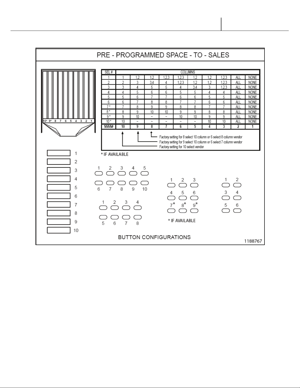
Space to Sales:
Allows you to program which column will vend when you choose a desired selection button.
There are 6 preset configurations (See inner door label for preset options). You also have the
option of doing a custom space to sales. To change current setting:
1. Press Button 4 when “Space to Sales” is displayed.
2. Press Button 4 to change current setting.
3. Press Button 2 or 3 to scroll through available settings.
4. Press Button 4 to save setting.
5. Press Button 1 to exit mode.
To customize your space to sales:
1. Press Button 4 when “Space to Sales” is displayed.
2. Press Button 2 or 3 to scroll until display reads “Space to Sales - Custom.”
3. Press Button 4. Display reads “Clear Settings?”
4. Press Button 4 to clear. Display reads “Custom Sel X - None.”
5. Press Button 4 to change a selection assignment.
6. Press Button 4 to assign (flashing) or unassigned (not flashing or steady) columns.
7. Press Button 1. Display reads “Save?”
8. Press Button 4 to save.
9. Press Button 1 to exit the mode.
Set Program Password:
Allows the operator to set a password to access Sales Data when the door is closed. Please note
that this function will not work if the password is set at 0000.
1. Press Button 4 at “Closed Door Password” mode.
2. The current password will be displayed.
3. Press Button 2 or 3 while each digit is flashing to change current password.
4. Press Button 4 to save and advance to next digit.
5. Press Button 4 after the 4th digit to exit mode.
Set Language:
This Mode allows you to program different languages on the controller. The current languages
available are English, Spanish, and French.
1. Press Button 4 at “Set Language” mode. The current language will be displayed.
2. To change current language, press Button 4 to start language flashing.
3. Press Button 2 or 3 to choose a language.
4. Press Button 4 to save the language change.
5. Press Button 1 to exit mode.
Set Clock:
If the “Timing Features” in the “Configuration” mode are turned ON, you will have access to
this mode. This mode allows you to set the current month, day, year, hour and minute.
V21 12.4 Programming HV3 / CHAMELEON | P1-8
Page 43

V21 Parts & Service Manual
All V21 Identified Equipment
REV A – 10/2013
P/N: 1230255
To set the clock:
1. Press Button 4 at the “Set Clock” prompt. You will be able to scroll through the following
options by pressing Button 2 or 3.
- Enable ON/OFF - This will turn the clock timer on or off.
- MM/DD/YYYY HH:MM - This is the current time and date.
- Daylight Savings
2. Press Button 4 to change current setting. The current setting will begin to flash.
3. Press Button 2 or 3 to change current setting.
4. Press Button 4 to save current setting.
Lighting:
If the “Timing Features” in the “Configuration” mode are turned ON, you will have access to
this mode. This mode allows you to turn the lights on/off with the internal timer.
1. Press Button 4 when the display reads “Start Time 1” or “Start Time 2.”
2. Press Button 4 at “Start Time 1” or “Start Time 2.”
3. Press Button 4 at “Start Day 1” or “Start Day 2.”
4. Scroll through the days of the week or “all” with Button 2 or 3.
5. Press Button 4 to change current setting.
6. Change setting by pressing Button 2 or 3.
7. Press Button 4 to save changes.
8. Press Button 2 or 3 at “Start 100.00” or “Start 200.00”
9. Press Button 4 to change time.
10. Press Button 2 or 3 to set time.
11. Press Button 4 to save.
12. Press Button 1 to exit mode.
13. Repeat process with “Stop Time 1” or “Stop Time 2.”
Refrigeration:
If ‘Timing Features’ in Configuration Mode are ‘Off’, you will only have access to the following
features:
Set Point Temperature
Sensor Reading
Degree Setting
Fan Energy Mode
Periodic Defrost Mode
To change the set point temperature:
1. Press Button 4 when the display reads “Refrigeration.”
2. The display will read “Set Point XX” with the current setting displayed.
3. To change the setting press Button 4 and the current set point temperature will begin to flash.
4. Press Button 2 or 3 to increase or decrease the set point.
V21 12.4 Programming HV3 / CHAMELEON | P1-9
Page 44

V21 Parts & Service Manual
All V21 Identified Equipment
REV A – 10/2013
P/N: 1230255
5. Press Button 4 to save changes.
6. Press Button 1 to exist and return “Refrigeration” on display.
To display the temperature:
1. Press Button 4 when the display reads “Refrigeration.”
2. Press Button 2 or 3 until the display reads “Sensor Reading.”
3. Press Button 4 and the current temperature will be shown in Fahrenheit or in Celsius.
4. Press Button 1 to exit and return the display to “Refrigeration.”
To change the degree scale:
1. Press Button 4 when the display reads “Refrigeration.”
2. Press Button 2 or 3 until the display reads “Degree Setting.”
3. The display will show the current degree scale (Celsius or Fahrenheit).
4. Press Button 4 and the degree scale will begin to flash.
5. Press Button 2 or 3 to choose setting.
6. Press Button 4 to save setting.
7. Press Button 1 to exit and return the display to “Refrigeration.”
To change the Fan Energy Savings mode:
1. Press Button 4 when the display reads “Refrigeration.”
2. Press Button 2 or 3 until the display reads “Fan.”
3. The display will read “Fan X” with the current setting displayed.
4. To change the setting press Button 4 and the current Fan mode will begin to flash.
5. Press Button 2 or 3 to increase or decrease the Fan mode.
6. Press Button 4 to save changes.
7. Press Button 1 to exit and return the display to “Refrigeration.”
The refrigeration system shall have three types of fan mode operation (energy conservation
modes) – This requires fan relay needs to be installed.
Fan Mode 0 (Disable)
The refrigeration system shall have a fan mode of operation in which the evaporator fan will be
turned on/off based on the activation of compressor. When the fan mode 0 is activated through
the Service Modes, the controller shall always turn on evaporator fan.
Fan Mode 1
The refrigeration system shall have a fan mode of operation in which the evaporator fan will be
turned on/off based on the activation of compressor. When the fan mode 1 is activated through
the Service Modes, the controller shall turn off evaporator fan after the delay for 5 minutes after
the compressor is turned off. And when the compressor is turned on, the controller shall turn on
evaporator fan at same time.
The fan mode 1 does not function for 24 hours from the pull-down mode start.
V21 12.4 Programming HV3 / CHAMELEON | P1-10
Page 45

V21 Parts & Service Manual
All V21 Identified Equipment
REV A – 10/2013
P/N: 1230255
Fan Mode 2
The refrigeration system shall have an fan mode of operation in which the evaporator fan will be
turned on/off based on the number of vended product per unit hour . When the fan mode 2 is
activated through the Service Modes the controller shall turn on/off the compressor and
evaporator fans, based on the following method.
When the number of vended product per one hour is equal or less than five, the controller should
enter the fan mode 1. This causes the controller to work as fan mode 1 without any setting
change.
When the number of vended product per one hour is more than five, the controller should enter
the normal operation mode.
The fan mode 2 does not function for 24 hours from the pull-down mode start.
To change the Periodic Defrost Mode:
1. Press Button 4 when the display reads “Refrigeration.”
2. Press Button 2 or 3 until the display reads “Periodic Defrost.”
3. The display will show it on or off.
4. Press Button 4 and the setting value will flash.
5. Press Button 2 or 3 to choose your setting.
6. Press Button 4 to save setting.
7. Press Button 1 to exit and return the display to “Refrigeration.”
If the “Timing Features” in the Configuration mode are turned ON, you will have additional
access to the following modes:
Enable
Start Time 1 or Start Time 2
Start Day 1 or Start Day 2
Start 100.00 or Start 200.00
Stop Time 1 or Stop Time 2
Stop Day 1 or Stop Day 2
Stop 100.00 or Stop 200.00
Sales Block 1 and 2:
Allows you to program the machine to turn off and on at regular intervals.
To program the blocking feature, you must enter the following information:
Start Time- When the machine turns off
Start Days
Stop Time
- When the machine turns back on
Stop Days
Selections
Discount:
Allows you to program the machine to discount beverages at regular intervals.
V21 12.4 Programming HV3 / CHAMELEON | P1-11
Page 46

V21 Parts & Service Manual
All V21 Identified Equipment
REV A – 10/2013
P/N: 1230255
To program the “Discount” feature, you must enter the following information:
Start Time- When the discounting begins
Start Day
Stop Time
- When the discounting ends
Stop Day
Selections
Amount
– Amount subtracted/discounted from original vend price
Override:
Allows various items to be enabled or disabled depending on the status of an attached override
switch.Additional override switch is required – kit # 1124429
Each of the following items can be enabled by setting an ON or disabled by setting an OFF.
“Override Free Vend”
“Override Sales Blocking”
“Override Discount”
“Override Light Timing”
“Override Refrigeration”
Return:
Exits the programming mode and returns the vendor to stand-by.
V21
12.4 Programming HV3 / CHAMELEON | P1-12
Page 47

V21 Parts & Service Manual
All V21 Identified Equipment
REV A – 10/2013
P/N: 1230255
V21 12.4 Programming HV3 / CHAMELEON | P1-13
Page 48
V21 Parts & Service Manual
All V21 Identified Equipment
REV A – 10/2013
P/N: 1230255
V21 12.4 Programming HV3 / CHAMELEON | P1-14
Page 49

V21 Parts & Service Manual
All V21 Identified Equipment
REV A – 10/2013
P/N: 1230263
12.4 PROGRAMMING
COKE CHAMELEON
V21 12.4 Programming Coke Chameleon | P2-1
Page 50

V21 Parts & Service Manual
All V21 Identified Equipment
REV A – 10/2013
P/N: 1230263
VEC COKE CHAMELEON PROGRAMMING OPERATION
NOTE: Some units may contain a European font display, in which case the “°” symbol will
be replaced by the “ß” symbol. Example: 72°F will be 72 ß F.
The VEC 12.6 Controller uses a 4-button programming system:
Programming Buttons: # 1 – Escape/Exit
# 2 – Decrease/Scroll Down
# 3 – Increase/Scroll Up
# 4 – Enter and/or Save
To access Mode functions, open the door. Locate the Mode Button on the Main Control Board
and press until Diagnostics appears. Use selection button 2 or 3 to navigate through the modes.
The Modes are as follows:
Diagnostics
Coin Payout
Tube Fill
Recycler Payout*
Recycler Fill*
Test Mode
Password
Cash Data
Sales Data
Set Price
Correct Change Only
Set Depth
Configuration
Space to Sales
Door Closed Password
Set Language
Set Clock **
Lighting **
Refrigeration ***
Sales Block 1 **
Sales Block 2 **
Discount **
Override ***
Return
* These modes will only appear if a recycler is being used in MDB level 4 mode.
** These modes will only appear when the “Timing Feature” in Configuration is turned On.
*** Limited options appear in this mode depending on whether the Timing Feature in
Configuration is On/Off.
V21 12.4 Programming Coke Chameleon | P2-2
Page 51

V21 Parts & Service Manual
All V21 Identified Equipment
REV A – 10/2013
P/N: 1230263
Please note: All modes except Diagnostics, Coin Payout, Tube Fill, Recycler Payout, Recycler
Fill, Test Mode are password protected.
Diagnostics:
Diagnostics Mode displays the error in the vendor to help diagnose the problem.
See inner door of vendor or Troubleshooting section for errors.
To view the detailed error
1. Press Button 4 to enter into “Diagnostics” Mode
2. If there are no errors the display will read “ Error None” otherwise the display will show the
top level error
3. Press Button 4 to view the detailed error
4. Press Button 2 or 3 to scroll to check for more errors
Refer to troubleshooting section for diagnosing the errors
5. Press Button 1 to exit
To Clear the error
1. Scroll to view the detailed error
2. Press and hold Button 4 for 2 seconds – the error wi ll clear.
3. Press Button 1 to exit mode.
Coin Payout:
Coin Payout Mode allows the operator to ‘test’ for proper operation of the changer tubes.
1. Press Button 4 to enter into “Coin Payout” mode
2. Press Button 2 or 3 to scroll to desired denomination
3. Press Button 4 to dispense displayed denomination
4. Press Button 1 to exit mode
Tube Fill:
Allows you to fill the coin tubes via the external coin insert. This is the recommended way to fill
the coin tubes because the control board is able to keep an accurate count of the coins.
1. Press Button 4 to enter into “Tube Fill” mode.
2. Insert coins into coin insert slot and the controller will “count” the number of coins going
into the coin mechanism.
The Recycler Payout and the Recycler Fill Modes are displayed only if the vendor is connected
with a recycler unit compatible in a MDB 4.0. Please note the Recycler Mode is to check the bill
accepted and dispensed by the Bill Recycler and not the bills accepted by the Bill Validator.
Bill Validator can accept equal or more bill types than the recycler but cannot dispense any bills.
Recycler Payout:
Recycler Payout Mode allows the operator to test the dispense operation of the bill recycler unit.
This mode will only be displayed if the vendor is connected with a recycler unit in a MDB 4.0.
V21 12.4 Programming Coke Chameleon | P2-3
Page 52

V21 Parts & Service Manual
All V21 Identified Equipment
REV A – 10/2013
P/N: 1230263
1. Press Button 4 to enter into “Recycler Payout” mode. The display will show the bill
denomination and the count of bill that the recycler can dispense.
2. Press Button 4 to dispense displayed denomination bill.
3. Press Button 1 to exit mode.
Recycler Fill:
Recycler Fill Mode allows the operator to test the bill acceptance of the bill recycler unit.
This mode will only be displayed if the vendor is connected with a recycler unit in a MDB 4.0.
1. Press Button 4 to enter into “Recycler Fill” Mode – the display will read “Enable Test”
2. Press Button 4 to enter the mode. The display will show the bill denomination and the count
of bill that the recycler can accept.
3. Insert the bill in the recycler – the recycler will only accept the bill it is programmed for.
Please note: The bill denomination displayed in this mode is the type of bill the bill recycler
is programmed to accept/dispense. To change the bill denomination on the recycler, please
refer to the recycler manual.
Test Mode:
Allows you to test vend a column, jog a column, test selection switches, display, refrigeration
system, lights, and heater.
Vending a Column:
1. At “Test Mode”, press Button 4. Display will read –“Test Mode – Vending”
2. Press Button 4 to enter – the display will read “Column 1”.
3. Press Button 2 or Button 3 to scroll to the desired column.
4. Press Button 4 to vend.
a. If motor vends OK, DISPLAY will read “Test Mode - Vending Motor OK”
b. If motor does not test OK on one of the following messages will appear:
- “Test Mode - Vending Fail - Column Jam”
- “Test Mode - Vending Fail - No Connection”
- “Test Mode - Vending Fail - High Current”
Jogging a Column:
1. At “Test Mode” press Button 4.
2. Press Button 2 or 3 to scroll to “Test Mode - Jog.”
3. Press Button 4 and display will read “Column 1.”
4. Press Button 2 or 3 to scroll to desired column.
5. Press Button 4 to enter into column and display will read “Column X Forward” with X
being the desired column.
6. Press Button 2 or 3 to scroll between “Forward” or “Reverse.”
7. Press Button 4 to move/jog the motor in the desired position.
8. Press Button 1 to exit this mode.
12.4 Programming Coke Chameleon | P2-4
V21
Page 53

V21 Parts & Service Manual
All V21 Identified Equipment
REV A – 10/2013
P/N: 1230263
Test Mode Display:
Allows you to verify that all of the characters on the display illuminate.
1. At “Test Mode” press Button 4.
2. Press Button 2 or 3 to scroll until display reads “Test Mode - Display.”
3. Press Button 4.
4. All of the characters on the display should illuminate.
5. Press Button 4 to exit.
Selection Switch Testing:
Allows you to test the selection switches.
1. At “Test Mode” press Button 4.
2. Press Button 2 or 3 to scroll to “Test Mode Switches”.
3. Press Button 4
4. Press desired selection switch to be tested.
5. To exit press Button 1 and hold for 3 seconds.
Test Mode Relays:
Allows you to test the compressor, evaporator fan, light and heater in the vendor.
1. When “Test Mode” is displayed press Button 4.
2. Press Button 2 or 3 to scroll until display reads “Test Mode - Relays” and press Button 4.
3. Press Button 2 or 3 to advance through sub-modes.
4. Press Button 4 at “Compressor” prompt to test compressor.
5. Press Button 4 at “Light” prompt to test lighting system.
6. Press Button 4 at “Fan” prompt to test evaporator fan.
7. Press Button 4 at “Heater” prompt to test optional heater.
8. Press Button 1 to exit sub-modes.
Please note: The Fan test and Heater test requires additional hardware – Please call customer
service for this feature.
Password:
Allows you to enter the password protected area.
All modes except Diagnostics, Coin Payout, Tube Fill, Recycler Payout, Recycler Fill, Test
Mode are password protected.
Default password is “4 2 3 1”
1. When “Password” is displayed press Button 4, the display will read “Please Enter The
Password”
2. Press Button 4, 2, 3, 1 in consecutive sequence.
3. The display should read “Cash Data” to indicate that it is in password protected menu.
In case the password entered is invalid or if the user fails to enter the password within 10
seconds of entering password mode – then the display will switch back to “Password” mode
to enable the user to re-enter.
V21 12.4 Programming Coke Chameleon | P2-5
Page 54

V21 Parts & Service Manual
All V21 Identified Equipment
REV A – 10/2013
P/N: 1230263
Cash Data:
This Mode allows you to retrieve historical information regarding the money accepted by the
vendor. To clear the individual selection cash data, you must have the MIS Auto Reset in the
“Configuration” mode turned to ON.
1. When “Cash Data” is displayed press Button 4. The non-resettable historical data is
displayed.
2. Press Button 2 or 3 to display resettable individual selections.
3. To reset historical data, make sure the MIS Auto Reset is turned ON in the configuration
mode.
4. Press Button 1 to exit mode.
Sales Data:
This Mode allows you to retrieve historical information regarding the number of units sold by
vendor. To clear the individual selection sales data, you must have the “MIS Auto Reset” in the
“Configuration” mode turned ON.
1. When “Sales Data” is displayed, press Button 4. The non re-settable historical data is
displayed.
2. Press Button 2 or 3 to display resettable individual selections.
3. Press Button 1 to exit.
Discount Counter:
This mode allows you to view historical sales and cash data in the vendor that have been vended
at a discounted price. This mode is populated only if there have been a discounted sales.
1. When “Discount Counter” is displayed, press Button 4 to view total discount vend sales.
2. Press Button 2 or 3 to display discount counter for individual selections.
3. Press Button 1 to exit mode.
Free Counter:
This mode allows you to view historical sales in the vendor at a free vend mode. This mode is
visible only if there has been a sales on a free vend mode.
1. When “Free Counter” is displayed, press Button 4 to view total free vend sales.
2. Press Button 2 or 3 to display free counter for individual selections.
3. Press Button 1 to exit mode.
V21 12.4 Programming Coke Chameleon | P2-6
Page 55

V21 Parts & Service Manual
All V21 Identified Equipment
REV A – 10/2013
P/N: 1230263
Set Price:
This Mode allows you the option to price each selection to the same vend price, or price each
selection button independently.
1. When display reads “Set Price” press Button 4.
2. Press Button 2 or 3 to choose selections or “All.”
3. Press Button 4 to start the current vend price flashing.
4. Press Button 2 or 3 to increase or decrease price.
5. Press Button 4 to save your new programmed price.
6. Press Button 1 to exit mode.
Correct Change Only:
This mode allows you to manipulate the credit acceptance and customer display messages for use
of correct change.
Customer Overpay:
On- Money will be accepted when the “Use Exact Change” display is on and there is
insufficient coins in the coin tubes.
Off – Exact or sufficient change required to make a vend.
Correct Change:
This is the minimum amount of change needed in the coin mechanism before the controller
displays the “Use Exact Change” message.
Accept Value:
This is the largest denomination of any single form of currency that can be accepted without
the knowledge that the equivalent value of coins can be returned.
Set Depth:
This Mode allows you to set the depth of each column. In this mode, you have the option of
setting the columns for single, double, triple or quadruple depths.
1. When display reads “Set Depth” Press Button 4.
2. Press Button 2 or 3 to choose columns or “All.”
3. Press Button 4 to enter into the column and start the depth flashing.
4. Press Button 2 or 3 to scroll through the depth settings (1-4).
5. Press Button 4 to save your new depth setting.
6. Press Button 1 to exit mode.
Configuration:
This mode allows you to set the different configurations in the vendor.
Default options are underlined
Multi-Price
On - All selections can be programmed individually.
Off - All selections will be set to the same price as Selection 1.
V21 12.4 Programming Coke Chameleon | P2-7
Page 56

V21 Parts & Service Manual
All V21 Identified Equipment
REV A – 10/2013
P/N: 1230263
Timing Features*
On - Gives you access to the “Clock” settings and its associated modes.
Off - “Clock” settings and its associated modes are hidden.
Door Summary
On - Sales and cash data are displayed as soon as the outer door is opened or by
activating the door switch.
Off - Sales and cash data are not displayed when the door is opened.
MIS Auto Reset
On - Resets if the counter is checked and after the door is closed.
Off - Does not reset.
Save Credit Timer
On - Credit that is established will be displayed for five minutes unless someone
makes a vend or presses the coin return button - whichever comes first.
Off - Credit that is established will remain indefinitely unless someone either makes a
vend or presses the coin return button.
Force Vend
On - The consumer will not be able to insert a dollar into the validator, hit the coin return
and receive change without first attempting a vend.
Off - The consumer can insert a bill into the validator, press the coin return button and
receive change.
Multi-Vend:
On - The consumer may insert enough credit to make multiple vends. The credit will
remain on the display until an additional vend is made or the coin return button is
pressed.
Off - The consumer is allowed to make a single vend and the credit (if applicable),
will be returned after the completion of the vend.
Deny Escrow
On - The validator will stack all bills received.
Off - The validator will not stack the bills, rather it will hold them in escrow until a
vend is complete.
SO Indicator
On - A small round symbol will appear in the lower right hand corner of the display when
one column is sold out or the machine detects an error.
Off - The symbol will not appear.
Count by Selection/Price
COUNT BY SELECTION - Individual sales and cash data will be reported in unit sales.
COUNT BY PRICE - Individual sales and cash data will be reported by vend price.
V21 12.4 Programming Coke Chameleon | P2-8
Page 57

V21 Parts & Service Manual
All V21 Identified Equipment
REV A – 10/2013
P/N: 1230263
MIS Reset W/DEX
On - MIS data will be reset with a DEX read.
Off - MIS data will not be reset with a DEX read.
Display Scroll * (Available on version 14 and above)
On - The messages will scroll across the display and change.
Off - The messages will blink and change.
EMS DEX * (Available on version 14 and above)
On - The Energy Management System Sales pattern in the vendor can be captured via the
DEX data read.
Off – The Energy Management System Sales pattern in the vendor will not be sent out
via DEX data read.
Depth Learning * (Removed from version 14 and above)
On - The control board will “learn” the depth setting after one row of product in the
column is vended.
Off - The control board will not “learn” the depth setting.
Space to Sales:
Allows you to map the columns with the selection buttons.
Space to sales can be set by either choosing one of the 10 preset configurations or you can have
the option of doing a custom space to sales.
For space to Sales mapping, refer to Inner Door Label STS or STS Label in the manual.
To change current setting:
1. Press Button 4 when “Space to Sales” is displayed.
2. Press Button 4 to change current setting.
3. Press Button 2 or 3 to scroll through available settings.
4. Press Button 4 to save setting.
5. Press Button 1 to exit mode.
To customize your space to sales:
1. Press Button 4 when “Space to Sales” is displayed.
2. Press Button 2 or 3 to scroll until display reads “Space to Sales - Custom.”
3. Press Button 4. Display reads “Clear Settings?”
4. Press Button 4 to clear. Display reads “Custom Sel X - None.”
5. Press Button 4 to change a selection assignment.
6. Press Button 4 to assign (flashing) or unassigned (not flashing or steady) columns.
7. Press Button 1. Display reads “Save?”
8. Press Button 4 to save.
9. Press Button 1 to exit the mode.
V21 12.4 Programming Coke Chameleon | P2-9
Page 58

V21 Parts & Service Manual
All V21 Identified Equipment
REV A – 10/2013
P/N: 1230263
Door Closed Password:
Allows the operator to set a 4 digit password to access Sales,Cash Data when the door is closed.
The password is limited to 1 through 6. Default password is “4 2 3 1”
Please note that this function will not work if any of the password digit is set to 0.
1. Press Button 4 at “Closed Door Password” mode.
2. The current password will be displayed.
3. Press Button 2 or 3 while each digit is flashing to change current password.
4. Press Button 4 to save and advance to next digit.
5. Press Button 4 after the 4th digit to exit mode.
Set Language:
This Mode allows you to program different languages on the controller. The current languages
available are English, Spanish, and French.
1. Press Button 4 at “Set Language” mode. The current language will be displayed.
2. To change current language, press Button 4 to start language flashing.
3. Press Button 2 or 3 to choose a language.
4. Press Button 4 to save the language change.
5. Press Button 1 to exit mode.
Set Clock:
If the “Timing Features” in the “Configuration” mode are turned ON, you will have access to
this mode. This mode allows you to set the current month, day, year, hour and minute.
To set the clock:
1. Press Button 4 at the “Set Clock” prompt. You will be able to scroll through the
following options by pressing Button 2 or 3.
- Enable ON/OFF - This will turn the clock timer on or off.
- Daylight Savings
- DST – Off
- DST Stop Time
Press Button 4 to Set
Press Button 2/3 to scroll
1. Display will switch to Month, DAY, Week , Hour
Set the Daylight Savings Time accordingly – Default : 11/Sun/1st / 02
- DST Start Time
Press Button 4 to Set
Press Button 2/3 to scroll
1. Display will switch to Month, DAY, Week , Hour
Set the Daylight Savings Time accordingly – default : 03/Sun/2nd / 02
V21 12.4 Programming Coke Chameleon | P2-10
Page 59

V21 Parts & Service Manual
All V21 Identified Equipment
REV A – 10/2013
P/N: 1230263
- MM/DD/YYYY HH:MM - This is the current time and date.
Press Button 4 to Set
Press Button 2/3 to scroll
Set current date in the vendor.
Lighting:
If the “Timing Features” in the “Configuration” mode are turned ON, you will have access to
this mode. This mode allows you to turn the lights on/off with the internal timer.
Enable:0 – Disabled – Energy Saving mode disabled
1 – Lighting is regulated at timed intervals.
2 – Lighting is regulated based on sales activity-Refer to Energy Management System
Section
InActivity Time: 35 ( 0 -995 ) – Time to keep the lights on after activity for EMS activity. This is
only applicable when the lighting enable is set to “2”
Start Time 1: To turn off the light at the allocated time
Stop Time 1: To turn on the light at the allocated time
Start Time 2: To turn off the light at the allocated time
Stop Time 2: To turn off the light at the allocated time
Please note that the Enable option should be set to “1” to activate start / stop time. It is
not necessary to set start time 2 if the lighting time needs to be turned off only once in a day.
1. Press Button 4 when the display reads “Start Time 1” or “Start Time 2.”
2. Press Button 4 at “Start Time 1” or “Start Time 2.”
3. Press Button 4 at “Start Day 1” or “Start Day 2.”
4. Scroll through the days of the week or “all” with Button 2 or 3.
5. Press Button 4 to change current setting.
6. Change setting by pressing Button 2 or 3.
7. Press Button 4 to save changes.
8. Press Button 2 or 3 to scroll to the start time.
9. Press Button 4 to change time.
10. Press Button 2 or 3 to set time.
11. Press Button 4 to save.
12. Press Button 1 to exit mode.
13. Repeat process with “Stop Time 1” or “Stop Time 2.”
V21 12.4 Programming Coke Chameleon | P2-11
Page 60
V21 Parts & Service Manual
All V21 Identified Equipment
REV A – 10/2013
P/N: 1230263
Refrigeration: * Features on version 14 and above.
If ‘Timing Features’ in Configuration Mode are ‘Off’, you will only have access to the following
features:
Set Point Temperature: The cabinet temperature during the normal mode. Refrigeration cuts-in
two degrees above and cuts-off at a degree below the set point.
* Storage Temp: 45- Thisis the storage temperature during the energy saving mode.
* Display Temp. Off / On – The option to display the cabinet temperature in the display.
* Defrost Interval: 6h (1 –24 hrs) –The interval time for the compressor to perform a defrost
cycle routine.
* InActivity Time: 35m – Time for the refrigeration system to go into energy savings mode after
no sales activity – This is applicable if the Enable is set to “2”.
Sensor Reading:– Refrigeration Temperature reading inside the cabinet.
Degree Setting:– Can change the temperature to Celsius or Fahrenheit.
Fan Energy Mode: – Mode 0 – The fan turns off on door open and turns on door close
Mode 1 – The fan turns off 5 minutes after the compressor stops and starts
when the compressor turns on
Default - The fan is turned on all the time.
Please note that the fan mode 1 and mode 2 is optional and needs a special hardware.
Periodic Defrost Mode:– Enables the refrigeration system to perform periodic defrost cycle.
Enable0 – Disabled – Refrigeration is regulated based on set point..
1 – Refrigeration can be regulated at timed intervals.
2 – Refrigeration is regulated based on Sales Activity. Refer to Energy Management
System Section.
To change the set point temperature:
1. Press Button 4 when the display reads “Refrigeration.”
2. The display will read “Set Point XX” with the current setting displayed.
3. To change the setting press Button 4 and the current set point temperature will begin to
flash.
4. Press Button 2 or 3 to increase or decrease the set point.
5. Press Button 4 to save changes.
6. Press Button 1 to exist and return “Refrigeration” on display.
* To change the storage temperature:
1. Press Button 4 when the display reads “Storage Temp.”
2. The display will read “Storage Temp. 45” with the current setting displayed.
3. To change the setting press Button 4 and the current storage temperature will begin to
flash.
4. Press Button 2 or 3 to increase or decrease the storage temperature.
5. Press Button 4 to save changes.
6. Press Button 1 to exit
V21 12.4 Programming Coke Chameleon | P2-12
Page 61

V21 Parts & Service Manual
All V21 Identified Equipment
REV A – 10/2013
P/N: 1230263
* To change the Temperature Display:
1. Press Button 4 when the display reads “Temperature Display ”
2. The display will read “Temperature Display On” with the current setting displayed.
3. To change the setting press Button 4 and the On/Off begins to flash.
4. Press Button 2 or 3 to change to On or Off.
5. Press Button 4 to save changes.
6. Press Button 1 to exit
* To change the Defrost Interval
1. Press Button 4 when the display reads “ Defrost Interval “
2. The display will read Defrost Interval 06h
3. To change the interval time, press Button 4 and the time will flash.
4. Press Button 2 or 3 to decrease or increase the time.
5. Choose the right time and press Button 4 to set.
6. Press Button 1 to exit.
* To change the Inactivity Time ( Needs to have Enable Set to 2 )
1. Press Button 4 when the display reads “InActivity Time : 35m”
2. The time settings will flash.
3. Press Button 2 or 3 to increase or decrease the time.
4. Choose the right time and press Button 4 to set.
5. Press Button 1 to exit.
To display the temperature:
1. Press Button 4 when the display reads “Refrigeration.”
2. Press Button 2 or 3 until the display reads “Sensor Reading.”
3. Press Button 4 and the current temperature will be shown in Fahrenheit or in Celsius.
4. Press Button 1 to exit and return the display to “Refrigeration.”
To change the degree scale:
1. Press Button 4 when the display reads “Refrigeration.”
2. Press Button 2 or 3 until the display reads “Degree Setting.”
3. The display will show the current degree scale (Celsius or Fahrenheit).
4. Press Button 4 and the degree scale will begin to flash.
5. Press Button 2 or 3 to choose setting.
6. Press Button 4 to save setting.
7. Press Button 1 to exit and return the display to “Refrigeration.”
To change the Fan Energy Savings mode:
1. Press Button 4 when the display reads “Refrigeration.”
2. Press Button 2 or 3 until the display reads “Fan.”
3. The display will read “Fan X” with the current setting displayed.
4. To change the setting press Button 4 and the current Fan mode will begin to flash.
5. Press Button 2 or 3 to increase or decrease the Fan mode.
6. Press Button 4 to save changes.
7. Press Button 1 to exit and return the display to “Refrigeration.”
V21 12.4 Programming Coke Chameleon | P2-13
Page 62

V21 Parts & Service Manual
All V21 Identified Equipment
REV A – 10/2013
P/N: 1230263
The refrigeration system shall have three types of fan mode operation (energy conservation
modes) – This requires fan relay needs to be installed.
Fan Mode 0 (Disable)
The refrigeration system shall have a fan mode of operation in which the evaporator fan will be
turned on/off based on the activation of compressor. When the fan mode 0 is activated through
the Service Modes, the controller shall always turn on evaporator fan.
Fan Mode 1
The refrigeration system shall have a fan mode of operation in which the evaporator fan will be
turned on/off based on the activation of compressor. When the fan mode 1 is activated through
the Service Modes, the controller shall turn off evaporator fan after the delay for 5 minutes after
the compressor is turned off. And when the compressor is turned on, the controller shall turn on
evaporator fan at s ame ti me. The fan mode 1 do es not function for 24 hours from the pull-down
mode start.
Fan Mode 2
The refrigeration system shall have an fan mode of operation in which the evaporator fan will be
turned on/off based on the number of vended product per unit hour . When the fan mode 2 is
activated through the Service Modes the controller shall turn on/off the compressor and
evaporator fans, based on the following method.
When the number of vended product per one hour is equal or less than five, the controller should
enter the fan mode 1. This causes the controller to work as fan mode 1 without any setting
change. When the number of vended product per one hour is more than five, the controller
should enter the normal operation mode.
The fan mode 2 does not function for 24 hours from the pull-down mode start.
To change the Periodic Defrost Mode:
1. Press Button 4 when the display reads “Refrigeration.”
2. Press Button 2 or 3 until the display reads “Periodic Defrost.”
3. The display will show it on or off.
4. Press Button 4 and the setting value will flash.
5. Press Button 2 or 3 to choose your setting.
6. Press Button 4 to save setting.
7. Press Button 1 to exit and return the display to “Refrigeration.”
Please note: Altering the Set point, Storage Temperature, Defrost Interval and Periodic Defrost
Mode can affect the affect the cooling behavior of the vendor – Please call customer service for
any questions in regards to these settings.
If the “Timing Features” in the Configuration mode are turned ON, you will have additional
access to the following modes:
Enable
Start Time 1 or Start Time 2
V21 12.4 Programming Coke Chameleon | P2-14
Page 63

V21 Parts & Service Manual
All V21 Identified Equipment
REV A – 10/2013
P/N: 1230263
Start Day 1 or Start Day 2
Start 1 or Start 2
Stop Time 1 or Stop Time 2
Stop Day 1 or Stop Day 2
Stop 1 or Stop 2
Sales Block 1 and 2:
Allows you to program the machine to disable Sales/Lights at regular intervals.
To program the blocking feature, you must enter the following information:
Enable Off/On/Lights
Start Time
- When the machine turns off
Start Days
Stop Time
- When the machine turns back on
Stop Days
Selections
Discount:
Allows you to program the machine to discount beverages at regular intervals.
To program the “Discount” feature, you must enter the following information:
Start Time- When the discounting begins
Start Day
Stop Time
- When the discounting ends
Stop Day
Selections
Amount
– Amount subtracted/discounted from original vend price
Override:
Allows various items to be enabled or disabled depending on the status of an attached override
switch. Additional override switch is required – Kit # 1124429
Each of the following items can be enabled by setting an ON or disabled by setting an OFF.
“Override Free Vend”
“Override Sales Blocking”
“Override Discount”
“Override Light Timing”
“Override Refrigeration”
Return:
Exits the programming mode and returns the vendor to stand-by.
12.4 Programming Coke Chameleon | P2-15
V21
Page 64

V21 Parts & Service Manual
All V21 Identified Equipment
REV A – 10/2013
P/N: 1230263
ENERGY MANAGEMENT SYSTEM ( EMS )
Energy Management System is a feature that enables the vendor to control the refrigeration and
light system in the machine according to the sales pattern in order to achieve the maximum
energy efficiency.
Learn-and-React
It has a built-in-feature that learns th e sales p attern in the lo cation to mark a sal es-time-zone and
a no-sale-time-zone. The system reacts by regulating the illumination and refrigeration system
during the learnt time zones.
The illumination system is disabled and the products are stored at a higher temperature during
no-sales-hours.
In order to achieve set-point at the appropriate sales-time-zone, the regular refrigeration mode
will be activated 4 and half hours prior to the sales-time-zone.
Activate EMS System:
Open the door – press the mode switch on the VMC board –
The display will read – ‘Diagnostics’
1. Set Timing Feature.
1. Press Button 2 to scroll to “Configuration”
2. Press Button 4 to enter
3. Press Button 2 to scroll to “Timing Feature”
4. Press Button 4 – the “Off” will blink
5. Press Button 2 to change it to “On”
6. Press Button 4 to set.
2. Set Clock.
1. Press Button 2 to scroll to “Set Clock”
2. Set Time and Date
3. Set Refrigeration to EMS Mode
1. Press Button 2 to scroll to Refrigeration
2. Press Button 4 to enter
3. Press Button 2 to scroll to “Enable”
4. Press Button 4 to enter
5. Press Button 2 to scroll to “2”
6. Press Button 4 to set
4. Set Light to EMS mode
1. Press Button 2 to scroll to “Light”
2. Press Button 4 to enter
3. Press Button 2 to scroll to “Enable”
4. Press Button 4 to enter
5. Press Button 2 to scroll to “2”
6. Press Button 4 to set
De-Activate EMS system
Setting light Enable to ‘0’ and setting Refrigeration Enable to ‘0’ disables the EMS
system.
V21 12.4 Programming Coke Chameleon | P2-16
Page 65

V21 Parts & Service Manual
All V21 Identified Equipment
REV A – 10/2013
P/N: 1230263
V21 12.4 Programming Coke Chameleon | P2-17
Page 66
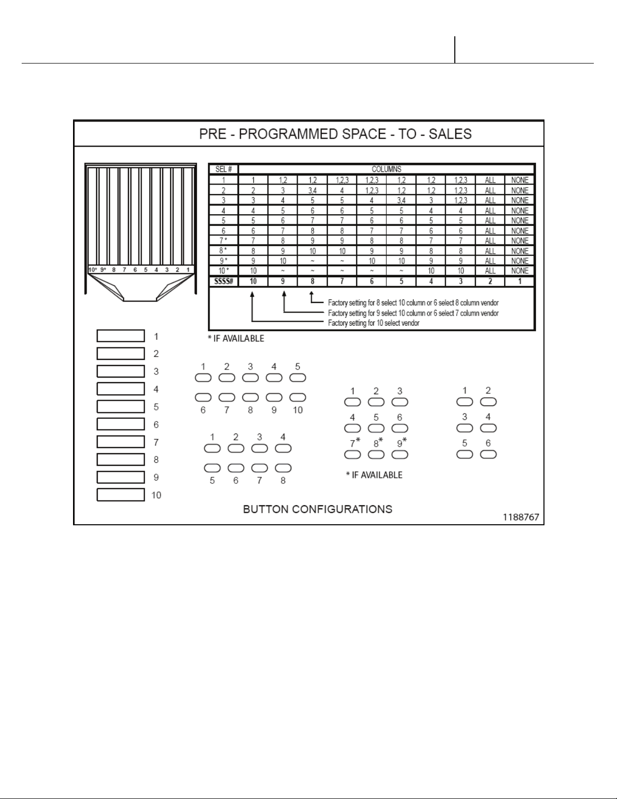
V21 Parts & Service Manual
All V21 Identified Equipment
REV A – 10/2013
P/N: 1230263
Figure to show Pre-Programmed Space to Sales:
V21 12.4 Programming Coke Chameleon | P2-18
Page 67

V21 Parts & Service Manual
All V21 Identified Equipment
REV A – 10/2013
P/N: 1230298
12.1 PROGRAMMING
TRADE
V21 12.1 Programming Trade | P3-1
Page 68
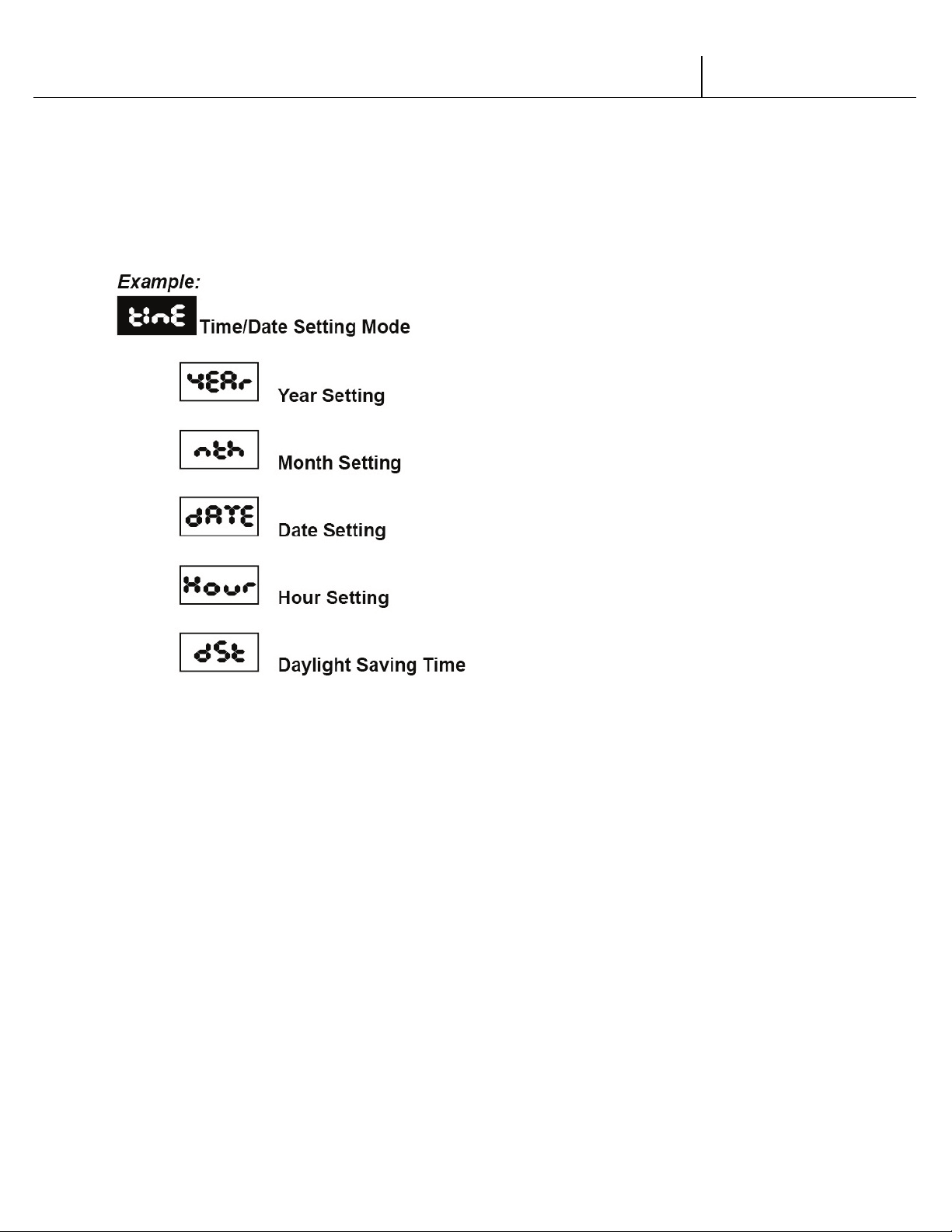
V21 Parts & Service Manual
All V21 Identified Equipment
REV A – 10/2013
P/N: 1230298
All programming of the V21 is done in the service mode as indicated in the following steps
below. The main service modes are indicated in white text and the sub-modes are indicated in
black text.
V21 12.1 Programming Trade | P3-2
Page 69
V21 Parts & Service Manual
All V21 Identified Equipment
REV A – 10/2013
P/N: 1230298
THREE-BUTTON PROGRAMMING
All programming of the V21 control board is done in the service mode. To enter the service
mode open the vendor door, find the service mode button located on the control board, then
press and release the service mode button. To scroll through all the service modes, use selection
button one.
The first three selection buttons are used to navigate through the programming as follows:
Button Description Usage
Selection Button 1 Up/Down Increase/Decrease, Next/Previous
Selection Button 2 Enter Go to sub-level, activate function
Selection Button 3 Exit Return to previous level, exit, save
FIGURE 1
The controller will automatically return to the Open-Door Sales Mode if:
1. No information from the selection switches is received within approximately 30 seconds.
2. The service mode button is pressed a second time.
3. The (Exit) button is pressed.
When the programming is entered, any established credit is returned. When and if the door is
closed, the controller will exit the service mode and return to the sales mode.
MIS Data
As soon as the outer door is opened, the non-resettable MIS data will be displayed if no errors
exist. “
the machine has sold. After 30 seconds, “
dollar amount the machine has accumulated. NOTE: Pressing selection button one will eliminate
the 30-second wait time and advance you immediately to the “
To access MIS data by individual selection, press selection button two during the “
or “
selections. Please see page PG-7 to choose between count by selection and count by price.
NOTE: The MIS data that is displayed when the outer door is opened (“
XX.XX”) is non-resettable. This data is accumulated over the life of the control board and can
only be changed by replacing the control board.
CAns XXX” will flash for approximately 30 seconds, indicating the total number of units
CASh XX.XX” will begin to scroll, indicating the total
CASh XX.XX” scroll.
CAnS XXXX”
CASh XX.XX” scroll. Use selection button one to advance forward or backward through the
CAnS XXXX” and CASh
12.1 Programming Trade | P3-3
V21
Page 70
V21 Parts & Service Manual
All V21 Identified Equipment
REV A – 10/2013
P/N: 1230298
SET-UP AND CODE DESCRIPTION
Eror Error Display Mode
If selection button two is pressed at the “Eror” prompt, the controller will enter the Error
Display Mode. If no errors have occurred, the display will show “
detected since the last error reset, the display will show the first error summary code that has
occurred. If selection button three is pressed while displaying any summary code, the controller
will return to the “
Note: See the Trouble Shooting section for errors and how to clear them.
Eror” prompt.
nonE”. If an error has been
EXAMPLE: “
CJO1” would indicate a column jam error in column 1.
COIn Coin Pay Out/Tube Fill Mode
If selection button two is pressed at the “COIn” prompt, the controller will enter the Coin Pay
Out Mode. Pressing selection one will scroll through the denominations and pressing selection
button two will start the denomination flashing. The display will indicate the denomination
along with the number of that coin stored in the coin mechanism. If selection button two is
pressed, a pay out of the displayed value will be made. Coins will continue to pay out as long as
that selection button is held down.
EXAMPLE: If selection button two is pressed while 5 cents is displayed it will pay out a nickel.
When the controller enters the “
coin changer’s acceptor when that coin’s tube is not full. The tube inventory level will be displayed
after each coin is accepted.
COIn” mode, the operator is allowed to deposit any coin into the
tESt Test Mode
If selection button two is pressed at the “tESt” prompt, the controller will enter the Test Mode
where you are able to test the motors, the display, the compressor, the lights, the evaporator
fans and the heater.
UEnd Vend Testing
Pressing selection button two at the test mode will enter the controller into the vend test mode.
Upon entry into the vend test mode the display will show the first summary test, “
(column 1). Pressing selection button one will scroll through the column selections. Pressing
selection button two will test vend the displayed column. In order to exit the setting, press
selection button three.
12.1 Programming Trade | P3-4
V21
COL1”
Page 71
V21 Parts & Service Manual
All V21 Identified Equipment
REV A – 10/2013
P/N: 1230298
SET-UP AND CODE DESCRIPTION (CONTINUED)
JoG Jogging the Column
Pressing selection button two at the “JoG” mode, will enter into the Jog test mode. Upon entry
into the Jog test mode the display will show the first summary test, “
selection button one will scroll through the column selections. Pressing selection button two will
access
motor in the desired direction. To exit the setting, press selection button three.
for (forward) or rEU (reverse). Pressing selection button two again will move the
COL1” (column 1). Pressing
dSP Display Testing
Pressing selection button one at the Jog test mode will advance the controller to the Display test
mode. Upon entry into the Display test mode the display will flash a series of lines and dashes if
all characters in the display are operational. To exit the setting, press selection button three.
rELY Relay Testing
Pressing selection button one at the display test mode will advance the controller into the Relay
test mode which allows the user to test the lights, compressor, evaporator fans or the heater.
Upon entry into the relay test mode the display will read “
scroll through the components for testing, press selection button one. To activate the
component, press selection button two and the “
to toggle between “
the component if the display reads “
0” (deactivate) and “1” (activate). Pressing selection button two will activate
XXX1”. To exit the setting, press selection button three.
0” will begin to flash. Use selection button one
cnPO” for the compressor test. To
CnPO/1 – Compressor test
Lit0/1 – Light test
FAn0/1 – Evaporator fan test
Htr0/1 – Heater testing
cASh MIS Data – Cash Mode
If selection button two is pressed at the “CASh” prompt, the display will show the nonresettable historical amount of money accepted by the machine. If selection button one is
pressed, the display will show “
button one. Continue pressing selection button one to scroll through all of the selections. To
exit the setting, press selection button three.
SL 1”(selection one) and the amount received for selection
12.1 Programming Trade | P3-5
V21
Page 72
V21 Parts & Service Manual
All V21 Identified Equipment
REV A – 10/2013
P/N: 1230298
SET-UP AND CODE DESCRIPTION (CONTINUED)
SALE MIS Data – Sales Mode
If selection button two is pressed at the “SALE” prompt, the display will show the nonresettable historical amount of units sold by the machine. If selection button one is pressed, the
display will show “
pressing selection button one to scroll through all of the selections. To exit the setting, press
selection button three.
SL 1” (selection one) and the units sold for selection button one. Continue
COSt Cost Setting Mode
The purpose of this mode is to enable the controller to set the vend price for each of the
selections. If selection button two is pressed at the “
COSt” prompt, the display will indicate “SL
1”. Pressing selection button one will scroll through all of the selections or “ALL” to have all the
vend prices set at the same price. Pressing selection button two will enter into the displayed
selection button. Pressing selection button one will change the displayed vend price. Pressing
selection button two again will save the price and selection button three will exit the mode.
dCtr Discount Counter (Only shows when discounts are used)
The discount counter allows you to access the sales and cash data for vends that have been
discounted. Press selection button #2 when the display reads
read
CASh. Press selection button #2 when the display reads CASh. The display will change to
read
CASh and XXXX.XX, where XXXX.XX is the value of all discounts towards paid sales. This
total is non-resettable and begins when the discount feature is enabled. Pressing selection
button #1 will scroll through all of the selection buttons and display the value of the discounts
toward product sales. The amounts for the individual selections can be reset using the rules in
oPts mode. To exit this mode, press selection button #3. The display will return to CASh.
the
To advance to the sales information, press selection button #1. The display
dCtr. The display will change to
CASh will change to
SALE. Press selection button #2 to access this information. The total number of discounted
sales will be displayed. This total is non-resettable and begins when the discount feature is
enabled. Pressing selection button #1 will scroll through all of the selection buttons and display
each selection’s number of discounted sales. The amounts for the individual selections can be
reset using the rules in the
oPts mode.
FCtr Free Counter (Only show if free vends during closed-door sales mode have been made)
The free counter allows you to access the sales and cash data (loss) for vends that have been
free. Press selection button #2 when the display reads
XXXX.XX, where XXXX.XX is the value of all lost money based on the price value setting. This
total is non-resettable and begins when the free vend override feature is enabled. Pressing
selection button #1 will change to the second screen. The display will change to read
XXX.XX. It will display the total number of free vends that have occurred. This total is non-
FCtr. The display will change to read
SALE
V21
12.1 Programming Trade | P3-6
Page 73

V21 Parts & Service Manual
All V21 Identified Equipment
REV A – 10/2013
P/N: 1230298
resettable and begins when the free vend override feature is enabled. Press selection button #3
to exit the mode.
V21 12.1 Programming Trade | P3-7
Page 74
V21 Parts & Service Manual
All V21 Identified Equipment
REV A – 10/2013
P/N: 1230298
SET-UP AND CODE DESCRIPTION (CONTINUED)
FS
bE
SE
SP
OP
dL
dSEt Depth Setting Mode
The purpose of this mode is to enable the controller to set the vending depth for each column.
If selection button two is pressed at the “
selection button one will scroll through all of the columns. Pressing selection button two will
enter into the displayed column. Pressing selection button one again will change the displayed
depth settings from 1-4. Pressing selection button two will save the depth setting and selection
button three will exit the mode.
dSEt” prompt, the display will indicate “0X”. Pressing
OPtS Option Mode
If selection button two is pressed at the “OPtS” prompt, the controller will enter the Option
mode. The purpose of this mode is to allow the controller to select the configuration options
desired. Default options are underlined.
Display Description Meaning
Force Select Force select enabled (y) or disabled (n)
ct
CC
SC
NU
AR
dt**
Bill Escrow Bill Escrow enabled (y) or disabled (n)
Error/Sold Out Indicator Error/Sold Out indicator “o” enabled (y) or disabled (n)
Single Price Single Price enabled (y)/Multi-Price enabled (n)
Count by Price/Count
by Selection
Correct Change Light
Allow Overpay Allow overpay enabled (y)/Allow overpay disabled (n)
Save Credit
Multi Vend
Learning Mode* Learning mode enabled (y)/Learning mode disabled (n)*
Auto MIS reset
Double Talk
y = count by price
n = count by selection
Correct Change Light enabled (y)/Correct Change Light
disabled (n)
Credit will remain for 5 minutes (y)/Credit will remain
indefinitely (n)
Multi vend enabled, single vend disabled (y)/ Single
vend enabled, multi vend disabled (n)
MIS data will reset with DEX read (y)/MIS data will not
reset with DEX read (n)
Enable Double Talk (y)/
Disable Double Talk (n)
FIGURE 2
V21 12.1 Programming Trade | P3-8
Page 75
V21 Parts & Service Manual
All V21 Identified Equipment
REV A – 10/2013
P/N: 1230298
* The learning mode uses self-adaptive logic to “learn” what the depth setting of the column is,
STS10
STS9
STS8
STS7
STS6
STS5
STS4
STS3
STS2
STS1
COL
COL
COL
COL
COL
COL
COL
COL
COL
COL 1 1
1,2 1 1
1,2,3
1,2 1 1,2
ALL
NONE
2 2 1,2 2 2
1,2,3
1,2 1 1,2
ALL
NONE
3 3 3 3 3
1,2,3 3 2 3 ALL
NONE
4 4 4 4 4 4 4 2 4
ALL
NONE
5 5 5 5 5 5 5 3 5
ALL
NONE
6 6 6 6 6 6 6 4 6
ALL
NONE
7 7 7 7 7 7 7 5 7
ALL
NONE
8 8 8 8 ~ 8 8 6 8
ALL
NONE
9 9 9 ~ ~ 9 ~ 7 9
ALL
NONE
10
10
10 ~ ~
10 ~ 8 9 ALL
NONE
11* ~ ~ ~ ~ ~ ~ 9 10
ALL
NONE
12* ~ ~ ~ ~ ~ ~
10
10
ALL
NONE
in the event that the control board depth setting isn’t programmed properly.
* Available in version 33 and above
SET-UP AND CODE DESCRIPTION (CONTINUED)
StS Space-to-Sales Setting Mode
If selection button two is pressed at the “StS” prompt, the controller will enter the Space-toSales option. Upon entry into this setting the display will show the current option setting.
Pressing selection button one will scroll through the various space to sales options as listed
below. Pressing selection button two will change the current option and selection button three
will save the desired option. For proper configuration settings refer to the label located on
the inner door shear panel (See figure 3.)
SPACE-TO-SALES CONFIGURATIONS
SEL#
FIGURE 3
*Where available
Note: If none of the space-to-sales configurations are suitable, the operator can use the Custom
Space-to-Sales Setting Mode.
CStS Custom Space-to-Sales Setting Mode
If selection button two is pressed at the “CStS” prompt, the controller will enter the Custom
Space-to-Sales option. Upon entry into this setting the display will show the current selection
setting followed by the columns connected to that selection button.
Programming Connection Option
12.1 Programming Trade | P3-9
V21
Page 76

V21 Parts & Service Manual
All V21 Identified Equipment
REV A – 10/2013
P/N: 1230298
If selection button two is pressed while “SL X” is displayed, the display will change to “C0 1”.
Pressing selection button one will increase or decrease the column number displayed. Pressing
selection button two will actuate the changed connection status of the column number
displayed. If the column number is flashing it is assigned to the selection that was entered. If the
column number is steady, it is not assigned to the selection button. To exit this mode, press
selection button three to display “SAVE”, then press selection 2 to confirm save.
EnrG Energy Management Mode
If selection button two is pressed at "EnrG" prompt , the controller will enter the Energy
Management Mode.
Available Options:
Each option will have its specific operational hours during which the EMS system will control the
illumination and refrigeration system to achieve maximum energy efficiency.
EP 0: Disable Energy otions
EP 1: Facilities where operating hours are between 6 am till 9 pm ( ex.Manufacturing facilities )
EP 2: Facilities where operating hours are between 7 am till 3 pm ( ex corporate / Schools )
EP 3: Facilities where operating hours are between 9 am till 9 pm ( ex Retail Stores )
St : 0,1,5,30 : If a sensor is present, this is the time the light will turn off after an inactivity period.
Please note : Activation of Clock is required - Please refer to Clock Setting in this manual.
SET-UP AND CODE DESCRIPTION (CONTINUED)
Cddr Closed Door Data Retrieval Mode
If selection button two is pressed at the “Cddr” prompt, the controller will enter the Closed
Door Data Retrieval Mode by displaying “
selection button number one while the digits are flashing will change the current password. The
available digits are 0-6. (See note below.) Pressing selection button two will save the change
and advance to the next digit. In order to save the password and exit the mode, press selection
button two while the last/fourth digit is flashing.
Note: If one of the digits in the password is “0” this feature will be disabled since selection button
“0” does not exist.
Note: This feature is not available when the vend price is set to “0.00”.
XXXX” where “XXXX” is the password. Pressing
LAnG Language Mode
If selection button two is pressed at the “LAnG” prompt, the controller will enter the Language
Mode by displaying the currently assigned language. The available languages are
English,
Frn – French, GEr – German, ItA – Italian, Port – Portuguese, and ESP – Spanish.
EnG –
V21
12.1 Programming Trade | P3-10
Page 77
V21 Parts & Service Manual
All V21 Identified Equipment
REV A – 10/2013
P/N: 1230298
Pressing selection button one will toggle though the language options. If selection button two is
YEAr
dAtE
Hour
dSt
CtLC
Enb
StrI
dAY
Hour
End1
dAY
Hour
pressed, the display will save the language change and return the display to
LAnG.
CLOC Clock Setting Mode
If selection button two is pressed at the “CLOC” prompt, the controller will enter the Clock
Mode which allows you to set the clock on the control board. This field must be set in order to
operate any modes associated with the time. Pressing selection button two while any of the
options are displayed will enter you in to the clock setting options. Pressing selection button
one will toggle you through the options. Pressing selection button three will exit this mode.
CLOCK SETTING OPTIONS
Current Year (Example: 2002)
Current Date (month, day)
Current Time (hours, minutes)
Daylight Savings Time
Clock Control
SET-UP AND CODE DESCRIPTION (CONTINUED)
LitE Lighting Control Mode
If selection button two is pressed at the “LitE” prompt, the controller will enter the Lighting
Control Mode which allows you to have the lights turned off and on during specific time periods
to conserve energy. Pressing selection button two while any of the settings are displayed will
enter you in to the light control settings. Pressing selection button one will toggle you through
the options. Pressing selection button three will exit this mode.
LIGHTING CONTROL SETTINGS
Lighting control enabled (1)/disabled (0)
Start Time – Time lights shut off
Days associated with start time
Hour associated with start time
End Time – Time lights turn back on
Days associated with end time
Hour associated with end time
V21 12.1 Programming Trade | P3-11
Page 78
V21 Parts & Service Manual
All V21 Identified Equipment
REV A – 10/2013
P/N: 1230298
Str2
2nd Start time – time lights shut off
dAY
Hour
End2
dAY
Hour
Days associated with 2nd start time
Hour associated with 2nd start time
2nd End Time – Time lights turn back on
Days associated with 2nd end time
Hour associated with 2nd end time
rFrG Refrigeration Mode
If selection button two is pressed at the “rFrG” prompt, the controller will enter the
Refrigeration Control Mode by displaying “
button two again enters the temperature settings from “hhhh”(warmest) to “cccc”(coldest).
Pressing selection button one will toggle through the settings. If selection button two is pressed,
the display will return to “
for temperature. To view the temperature, press selection button two. To change the degree
scale, press selection button two when the display reads “
change the current degree scale, press selection button one to scroll between F and C. Pressing
selection button two will return the display to “
SEtP”. Pressing selection button one will change the display to “tNP”
SEtP” for set point temperature. Pressing selection
ForC” for Fahrenheit or Celsius. To
ForC”.
Note: The displayed thermostat setting and the actual temperature sensor reading for
refrigeration control are listed below in Figure 4:
SET-UP AND CODE DESCRIPTION (CONTINUED)
Thermostat Setting Displayed cccc ccc cc c norn h hh hhh hhhh
Cut-in Temperature (F) 34° 35° 36° 37° 38° 39° 40° 41° 42°
Cut-out Temperature (F) 30° 31° 32° 33° 34° 35° 36° 37° 38°
Nominal Temperature (F) 32° 33° 34° 35° 36° 37° 38° 39° 40°
Nominal Temperature (C) 0 0.6 1.1 1.7 2.2 2.8 3.3 3.9 4.4
FIGURE 4
There are two sub-modes within the refrigeration mode that can be activated to achieve energy
conservation
The first sub-mode, FAnX, refers to an optional evaporator fan relay. When X =
V21
12.1 Programming Trade | P3-12
Page 79
V21 Parts & Service Manual
All V21 Identified Equipment
REV A – 10/2013
P/N: 1230298
0 - the fan mode is disabled and the evaporator will turn on/off with the activation of the
Enb
Str1
dAY
Hour
End1
dAY
Hour
Str2
dAY
Hour
End2
dAY
Hour
compressor
1 - (Fan Mode 1) the evaporator fan will turn off 5 minutes after the compressor fan is turned
off
The second sub-mode,
0 - the periodic defrost mode is disabled
1 - the machine will defrost every 6 hours for 30 minutes - used in high humidity
environments .
Within the refrigeration mode, there is also a refrigeration conservation mode which raises the
cabinet temperature 18º F or 10º C during specified periods of time. Pressing selection button
two while any of the settings are displayed will enter you in to the refrigeration control settings.
Pressing selection button one will toggle you through the options. Pressing selection button
three will exit this mode.
dEFX, refers to the Periodic Defrost mode. If X =
SET-UP AND CODE DESCRIPTION (CONTINUED)
REFRIGERATION CONTROL SETTINGS
Refrigeration control enabled (1)/disabled (0)
Start Time – Time temperature rises 18°F/10°C
“
nno” – Monday
Days associated with start time
Hour associated with start time
End Time – Time temperature returns
Days associated with end time
Hour associated with end time
2nd Start time – Time temperature rises 18°F/10°C
Days associated with 2nd start time
Hour associated with 2nd start time
2nd End Time – Time temperature returns
Days associated with 2nd end time
Hour associated with 2nd end time
12.1 Programming Trade | P3-13
V21
Page 80
V21 Parts & Service Manual
All V21 Identified Equipment
REV A – 10/2013
P/N: 1230298
“tUE” – Tuesday
CtL1
SbL1
Str1
dAY
hour
StP1
dAY
hour
“
UUE” – Wednesday
“
Thu” – Thursday
“
Fri” – Friday
“
SAt” – Saturday
“
Sun” – Sunday
“
ALL” – All Days
bLC1 Block Selection Setting
This feature is used to choose a group of selections and the time when those selections will be
blocked from vending product. If selection button two is pressed at the “
prompt, the controller will enter the Selection Blocking Control Mode. Upon entry into this
program, the display will show the first sub-mode “
blocking mode you are using. Using selection button one will let the operator toggle between
the following modes:
CtL1” or “CtL2” depending on which
bLC1” or “bLC2”
SET-UP AND CODE DESCRIPTION (CONTINUED)
BLOCK SELECTION OPTIONS
Controls blocking option
Set selection buttons – (y) assigned/(n) not assigned
Set time for machine to turn off
Set days for blocking to start
Set hours for blocking to start
Set time for machine to turn back on
Set days for blocking to stop
Set hours for blocking to stop
diSC Discount Setting Mode
This feature is used to choose a group of selections that will be discounted, the amount of
discount, and the time when the discount will occur. If selection button two is pressed at the
diSC” prompt, the controller will enter the Discount Setting Mode. Upon entry into this
“
program the display will show “
CtL1”. If selection button one is pressed it will toggle through
V21
12.1 Programming Trade | P3-14
Page 81
V21 Parts & Service Manual
All V21 Identified Equipment
REV A – 10/2013
P/N: 1230298
the discount setting mode as listed below. Pressing selection button three will save the settings
CtL1
SdSC
Strt
dAY
Hour
StoP
dAY
Hour
LESS
FrEn
bLCn
Litn
rFGn
dScn
and return to the “
diSC” mode.
DISCOUNT SETTING OPTIONS
Turns the discount setting On/Off
Set selection buttons – (y) assigned/(n) not assigned
Set time for discounting to begin
Set days to discount
Set time for discounting to begin
Set time for discounting to stop
Set days for discounting to stop
Set time to start (24 hours)
Set discount amount
SET-UP AND CODE DESCRIPTION (CONTINUED)
OUEr Over-Ride Mode (Units equipped with optional key switch)
This feature is used to allow you to manually over-ride (via a key switch) pricing, blocking, low
energy operation and discounting. If selection button two is pressed at the “
controller will enter the Over-Ride Mode. Upon entry into this program the display will show
FrEn”. If selection button one is pressed it will cycle through the override setting options as
“
listed below. Pressing selection button three will save the currently displayed setting and return
the operator to the “
OUEr” prompt.
OVER-RIDE SETTING OPTIONS
Enable/Disable free vend (Edit mode Y/N)
Selection blocking over-ride
Lighting over-ride
Refrigeration over-ride
Discounting over-ride
OUEr” prompt, the
FrEn Over-Ride Free Vend
V21 12.1 Programming Trade | P3-15
Page 82
V21 Parts & Service Manual
All V21 Identified Equipment
REV A – 10/2013
P/N: 1230298
If selection button two is pressed at the “FrEn” prompt, the controller will enter the Free Vend
Enable Option. Upon entry into this program the display will show the current setting “
Press selection button two. Pressing selection button one will toggle between “y” for enabled
and “n” for disable. Pressing selection button two will save the currently displayed setting.
Pressing selection button three will return the operator to the “
“Y” = Enable free vend.
“N” = Disable free vend.
FrEn” prompt.
FrEn”.
bLCn Over-Ride Selection Blocking
If selection button two is pressed at the “bLCn” prompt, the controller will enter the Selection
Blocking Over-Ride Enable Option. Upon entry into this program the display will show the
current setting “
between “Y” for enable and “N” for disable. Pressing selection button two will save the currently
displayed setting. Pressing selection button three will return the operator to the “
“Y” = Enable selection blocking.
“N” = Disable selection blocking
bLCn”. Press selection button two. Pressing selection button one will toggle
bLCn” prompt.
SET-UP AND CODE DESCRIPTION (CONTINUED)
Litn Over-Ride Lighting
If selection button two is pressed at the “Litn” prompt, the controller will enter the Lighting
Over-Ride Option. Upon entry into this program the display will show the current setting
Lit4” for enable and “Litn” for disable. Pressing selection button one will toggle between
“
“y” for enabled and “n” for disable. Pressing selection button two will save the currently
displayed setting. Pressing selection button three will return the operator to the “
“Y” = Enable Over-Ride Lighting blocking.
“N” = Disable Over-Ride Lighting blocking
Litn” prompt.
rFGn Over-Ride Refrigeration
If selection button two is pressed at the “rFGn” prompt, the controller will enter the
Refrigeration Over-Ride Option. Upon entry into this program the display will show the current
setting “
between “y” for enabled and “n” for disable. Pressing selection button two will save the currently
displayed setting. Pressing selection button three will return the operator to the “
“Y” = Enable refrigeration over-ride.
rFG4” for enable and “rFGn” for disable. Pressing selection button one will toggle
rFGn” prompt.
“N” = Disable refrigeration over-ride.
dSCn Over-Ride Discount
V21 12.1 Programming Trade | P3-16
Page 83

V21 Parts & Service Manual
All V21 Identified Equipment
REV A – 10/2013
P/N: 1230298
If selection button two is pressed at the “dSCn” prompt, the controller will enter the
Discounting Over-Ride Enable Option. Upon entry into this program the display will show the
current setting “
dSC4” for enable and “dSCn” for disable. Pressing selection button one will
toggle between “y” for enabled and “n” for disable. Pressing selection button three will save the
currently displayed setting and return the operator to the “
dSCn” prompt.
“Y” = Enable discount over-ride.
“N” = Disable discount over-ride.
12.1 Programming Trade | P3-17
V21
Page 84
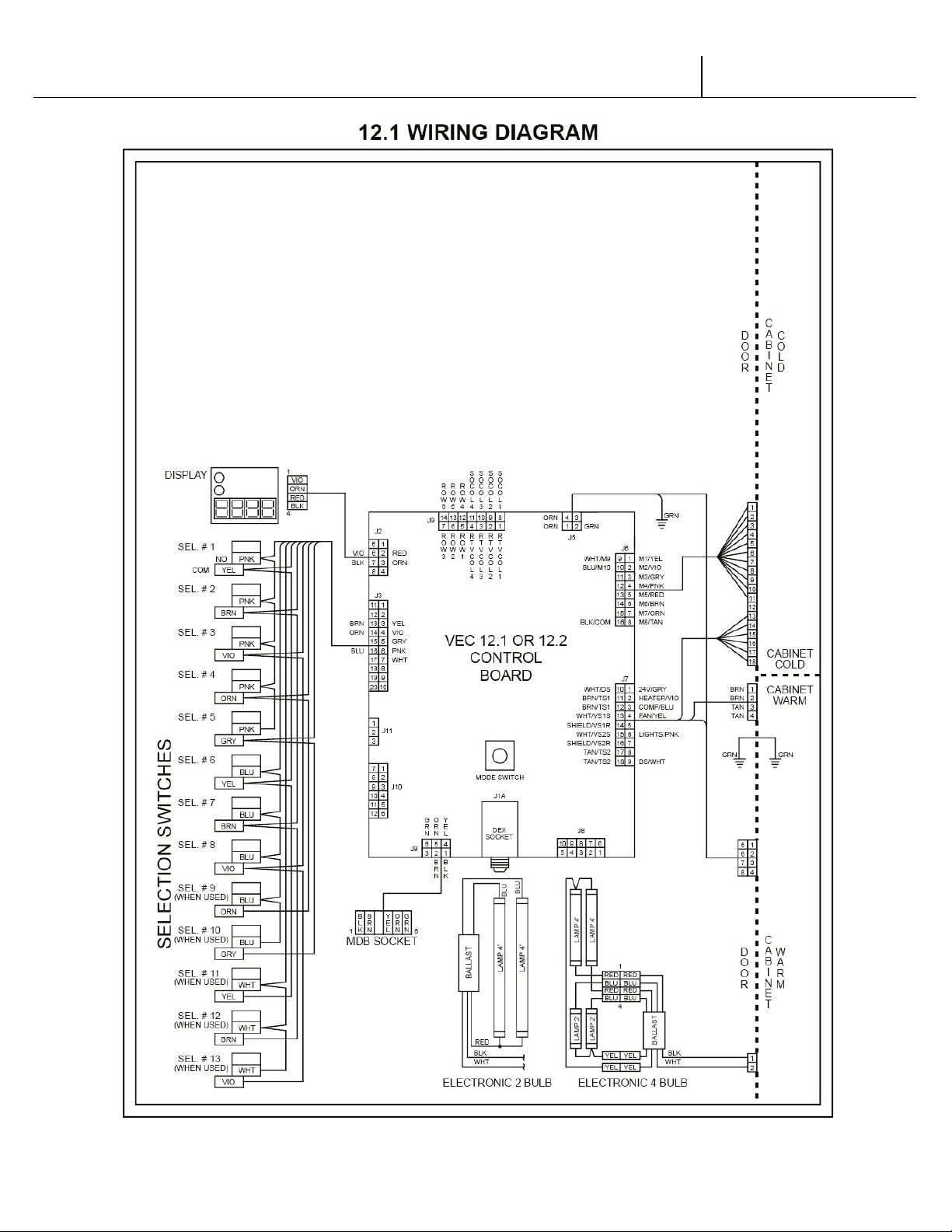
V21 Parts & Service Manual
All V21 Identified Equipment
REV A – 10/2013
P/N: 1230298
V21 12.1 Programming Trade | P3-18
Page 85
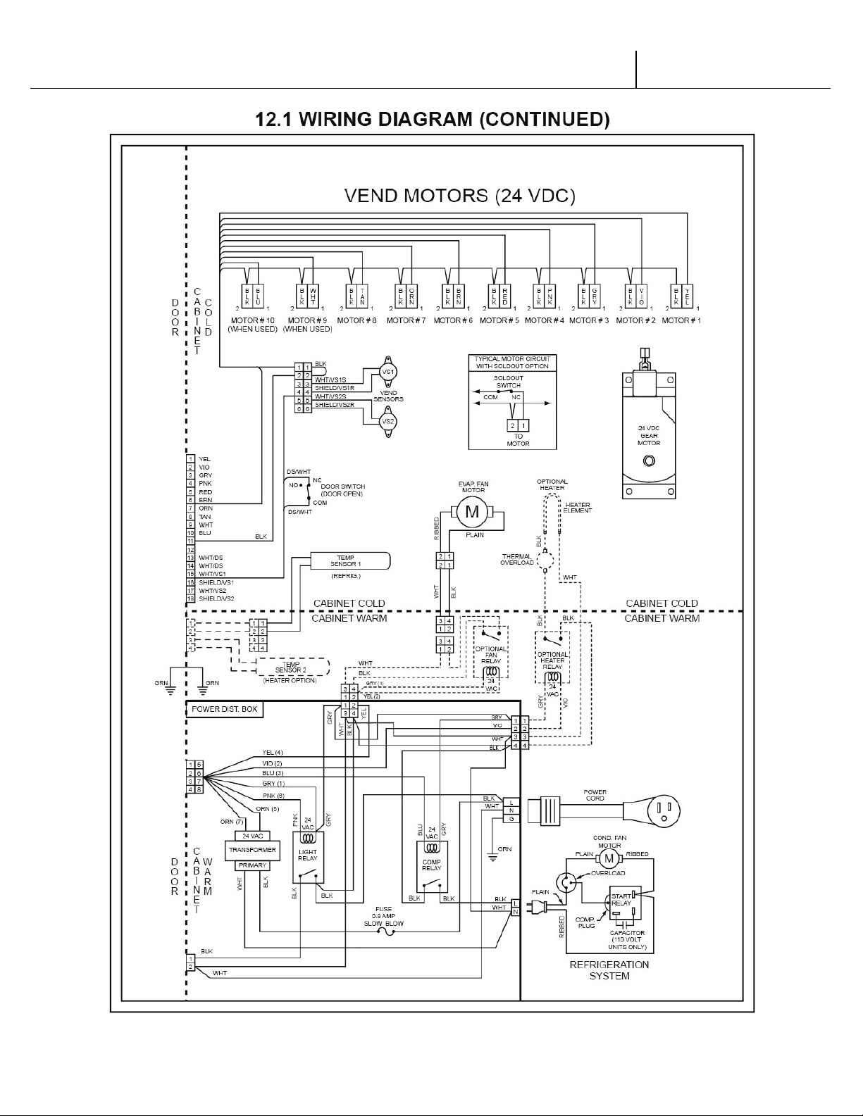
V21 Parts & Service Manual
All V21 Identified Equipment
REV A – 10/2013
P/N: 1230298
V21 12.1 Programming Trade | P3-19
Page 86

V21 Parts & Service Manual
All V21 Identified Equipment
REV A – 10/2013
P/N: 1230298
NOTE: If the outer door is left open for over an hour, the lights, and compressor will
become active. In order to over-ride this option, press the door switch one time.
12.1 Programming Trade | P3-20
V21
Page 87

V21 Parts & Service Manual
All V21 Identified Equipment
REV A – 10/2013
P/N: 1230328
HVV
12.3 PROGRAMMING
V21 12.3 Programming HVV | P4-1
Page 88

V21 Parts & Service Manual
All V21 Identified Equipment
REV A – 10/2013
P/N: 1230328
VEC 12.3 CONTROL BOARD OPERATIONS
NOTE: Some units may contain a European font display, in which case the “°” symbol will
be replaced by the “ß” symbol. Example: 72°F will be 72 ß F.
The VEC 12.3 Controller uses a 3-button programming system:
Row 1 (all selection buttons in top row) – Increase/Decrease
Row 2 (all selection buttons in top row) – Enter and/or Save
Row 3 (all selection buttons in top row) – Escape/Exit
In order to access Mode functions, open the door. Locate the Mode Button. Press the mode
button one time. Row 1 will take you through the modes.
The available modes are:
Diagnostics
Coin Payout
Tube Fill
Test Mode
Cash Data
Sales Data
Set Price
Set Depth
Configuration
Space to Sales
Door Closed Password
Set Language
Set Clock *
Lighting *
Refrigeration **
Sales Block 1 *
Sales Block 2 *
Discount *
Override **
Return
* These modes will only appear when the “Timing Features” in Configuration are turned ON.
** Limited options appear in these modes depending on whether the Timing Features are
ON/OFF.
V21 12.3
Programming HVV | P4-2
Page 89

V21 Parts & Service Manual
All V21 Identified Equipment
REV A – 10/2013
P/N: 1230328
Diagnostics:
See inner door of vendor or Troubleshooting section for errors and how to clear them.
Coin Payout:
Allows you to payout coin tubes.
• Press (2) to enter into “Coin Payout” mode.
• Press (1) to choose denomination.
• Press (2) to dispense displayed denomination.
• Press (3) to exit mode.
Tube Fill:
Allows you to fill coin tubes via the external coin insert. This is the recommended way to fill the
coin tubes because the control board is able to keep an accurate count of the coins.
• Press (2) to enter into “Tube Fill” mode.
• Insert coins into coin insert slot and the controller will “count” the number of coins going
into the coin mechanism.
Test Mode:
Allows you to test vend a column, jog a column, test selection switches, display, refrigeration
system, lights, and heater.
Vend Testing:
• At “Test Mode”, press (2)
• Display will read column X
• Press (1) to choose desired column
• Press (2) to vend
o If motor vends OK, DISPLAY will read “Test Mode - Vending Motor OK”
o If motor does not test OK one of the following messages will appear:
“Test Mode - Vending Fail - Column Jam”
“Test Mode - Vending Fail - No Connection”
“Test Mode - Vending Fail - High Current”
Jogging a Column:
• At “Test Mode” press (2)
• At “Test Mode – Vending” press (1)
• Display will read “Test Mode - Jog”
• Press (2) and display will read “Column 1”
• Press (1) to choose desired column
• Press (2) to enter into column and display will read “Column X Forward” with X being the
desired column.
• Press (1) to toggle between “Forward” or “Reverse”
• Press (2) to move/jog the motor in the desired position
• Press (3) to exit this mode
V21 12.3 Programming HVV | P4-3
Page 90

V21 Parts & Service Manual
All V21 Identified Equipment
REV A – 10/2013
P/N: 1230328
Test Mode Display:
Allows you to verify that all of the characters on the display illuminate.
1. At “Test Mode” press Button 4.
2. Press Button 2 or 3 to scroll until display reads “Test Mode - Display.”
3. Press Button 4.
4. All of the characters on the display should illuminate.
5. Press Button 4 to exit.
Selection Switch Testing:
Allows you to test the selection switches.
1. At “Test Mode” press Button 4.
2. Press Button 2 or 3 to scroll to “Test Mode Switches”.
3. Press Button 4
4. Press desired selection switch to be tested.
5. To exit press Button 1 and hold for 3 seconds
Test Mode - Relays:
Allows you to test the compressor, evaporator fan, lights and heater.
• At “Test Mode” press (2)
• Press (1) until display reads “Test Mode - Relays”
• Press (2)
• To advance through sub-modes, press (1)
• To test compressor, press (2) at “Compressor” prompt
• Press Button 4 at “Light” prompt to test lighting system.
• Press Button 4 at “Fan” prompt to test evaporator fan.
• To test optional heater, press (2) at “Heater” prompt
• To exit sub-modes, press (3)
Cash Data:
Allows you to retrieve historical information regarding the money accepted by the vendor. To
clear the individual selection cash data, you must have the “MIS Auto Reset” in the
“Configuration” mode turned to ON.
• Press (2) when the display reads “Cash Data”
• The non-resettable historical data is displayed
• To display resettable individual selections, press (1)
• To reset historical data, make sure the “MIS Auto Reset” is turned ON in the
configuration mode.
• To exit mode, press (3)
V21 12.3 Programming HVV | P4-4
Page 91

V21 Parts & Service Manual
All V21 Identified Equipment
REV A – 10/2013
P/N: 1230328
Sales Data:
Allows you to retrieve historical information regarding the number of units sold by vendor. To
clear the individual selection sales data, you must have the MIS Auto Reset in the
“Configuration” mode turned ON.
• Press (2) when the display reads “Sales Data”
• The non-resettable historical data is displayed
• To display resettable individual selections, press (1)
• To reset historical data, make sure the MIS Auto Reset is turned ON in the “Configuration”
mode.
• To exit mode, press (3)
Set Price:
Allows you to set the vend price of each selection. In this mode, you have the option of pricing
each selection button at the same vend price or price each selection button independently.
• Press (2) when display reads “Set Price”
• Pressing (1) will allow you to choose selections or “All”
• Pressing (2) will start the current vend price flashing
• Press (1) to increase/decrease the price
• Press (2) to save your new programmed price
• Press (3) to exit mode
Set Depth:
Allows you to set the depth of each column. In this mode, you have the option of setting the
columns for single, double, triple or quadruple depths.
• Press (2) when the display reads “Set Depth”
• Pressing (1) will allow you to choose columns or “All”
• Pressing (2) will enter you into the column and start the depth flashing
• Press (1) to scroll through the depth settings (1-4)
• Press (2) to save your new depth setting
• Press (3) to exit mode
V21 12.3 Programming HVV | P4-5
Page 92

V21 Parts & Service Manual
All V21 Identified Equipment
REV A – 10/2013
P/N: 1230328
Configuration:
There are various options that you can turn ON/OFF. Default options are underlined.
Multi-Price
ON = All selections can be programmed individually.
OFF = All selections will be set to the same price as Selection 1.
Timing Features*
ON = Gives you access to the “Clock” settings and its associated modes.
OFF = “Clock” settings and its associated modes are hidden.
Door Summary
ON = Sales and cash data are displayed as soon as the outer door is opened or by
activating the door switch.
OFF = Sales and cash data are not displayed when the door is opened.
MIS Auto Reset
ON = Resets if the counter is checked and after the door is closed.
OFF = Does not reset.
Consumer Overpay
ON = A dollar bill will be accepted even if the correct change light is on and there is
insufficient change in the coin tubes.
OFF = A vend will not be allowed when the correct change light is on and the consumer
attempts to use the dollar bill validator.
Save Credit Timer
ON = Credit that is established will be displayed for five minutes unless someone either
makes a vend or presses the coin return button - whichever comes first.
OFF = Credit that is established will remain indefinitely unless someone either makes a
vend or presses the coin return button.
Force Vend
ON = The consumer will not be able to insert a dollar into the validator, hit the coin
return and receive change without first attempting a vend.
OFF = The consumer can insert a bill into the validator, press the coin return button and
immediately receive change.
Multi-Vend:
ON = The consumer may insert enough credit to make multiple vends. The credit will
remain on the display until an additional vend is made or the coin return button is
pressed.
OFF = The consumer is allowed to make a single vend and the credit (if applicable),
will be returned after the completion of the vend.
V21 12.3 Programming HVV | P4-6
Page 93

V21 Parts & Service Manual
All V21 Identified Equipment
REV A – 10/2013
P/N: 1230328
Deny Escrow
ON = The validator will stack all bills received.
OFF = The validator will not stack the bills, rather it will hold them in escrow until a
vend is complete.
SO Indicator
ON = A small symbol will appear in the lower right hand corner of the display when at
least one column is sold out or the machine detects an error.
OFF = The symbol will not appear.
Count by Selection/Price
COUNT BY SELECTION = Individual sales and cash data will be reported in unit sales.
COUNT BY PRICE = Individual sales and cash data will be reported by vend price.
MIS Reset W/DEX
ON = MIS data will be reset with a DEX read.
OFF = MIS data will not be reset with a DEX read.
Depth Learning
ON = The control board will “learn” the depth setting after one row of product in the
column is vended.
OFF = The control board will not “learn” the depth setting.
Display Temperature
ON = Display the refrigeration temperature.
OFF = Do not display the refrigeration temperature.
# of Selections 6/12
Number of Selections: 6 = 6 select vendor
Number of Selections: 12 = 12 select vendor
• To adjust any of the settings, press (2) at “Configuration” mode.
• Press (1) to scroll through modes.
• Press (2) to change the mode. The current setting will begin to flash.
• Press (1) to change current setting.
• Press (2) to save change.
• Press (3) to exit sub-mode.
DSP MSG
Pepsi = Displays brand name.
Beverages = Displays generic name.
V21 12.3
Programming HVV | P4-7
Page 94

V21 Parts & Service Manual
All V21 Identified Equipment
REV A – 10/2013
P/N: 1230328
Space to Sales:
Allows you to program which column will vend when you choose a desired selection button.
There are 6 preset configurations (See inner door label for preset options). You also have the
option of doing a custom space to sales. To change current setting:
• Press (2) at “Space to Sales” prompt.
• Press (2) to change current setting.
• Press (1) to scroll through available settings.
• Press (2) to save setting.
• Press (3) to exit mode.
To customize your space to sales:
• Press (2) at “Space to Sales” prompt.
• Press (1) until the display reads “Space to Sales - Custom.”
• Press (2) and the display will begin to scroll the current configuration.
• To change a selection assignment, press (2).
• To assign (flashing) or unassign (no flashing/steady) columns, press (2).
• Pressing (3) will ask “Save?”
• Press (2) to save and (3) to exit the mode.
Door Closed Password:
Allows you to set a password to access Sales Data only when the door is closed. Please note that
this function will not work if the password is set at 0000.
• Press (2) at “Closed Door Password” mode.
• The current password will be displayed.
• To change current password, press (1) while each digit is flashing.
• Press (2) to save and advance to next digit, valid digits are 1-6
• Press (2) after the 4th digit to exit mode.
Set Language:
Allows you to program different languages on the controller. The current languages available
are English, Spanish, and French.
Set Clock:
If the “Timing Features” in the “Configuration” mode are turned ON, you will have access to this
mode. This mode allows you to set the current month, day, year, hour and minute.
To set the clock:
• Press (2) at “Set Language” mode.
• The current language will be displayed.
• To change current language, press (2) to start language flashing.
• Press (1) to choose a language.
• Press (2) to save the language change.
• Press (3) to exit mode.
V21 12.3
Programming HVV | P4-8
Page 95

V21 Parts & Service Manual
All V21 Identified Equipment
REV A – 10/2013
P/N: 1230328
• Press (2) at the “Set Clock” prompt. You will be able to scroll through the following
options by pressing (1).
o “Enable ON/OFF” - This will turn the clock timer on or off.
o “MM/DD/YYYY HH:MM” - This is the current time and date.
o “Daylight Savings”
• To change current setting, press (2).
• The current setting will begin to flash.
• Press (1) to change current setting.
• Press (2) to save current setting.
Lighting:
If the “Timing Features” in the “Configuration” mode are turned ON, you will have access to this
mode. This mode allows you to turn the lights on/off with the internal timer.
• Press (2) when the display reads “Start Time 1” or “Start Time 2.”
• Press (2) at “Start Time 1” or “Start Time 2.”
• Press (2) at “Start Day 1” or “Start Day 2.”
• Scroll through the days of the week or “all” with (1).
• To change current setting, press (2).
• Change setting with (1).
• Save changes with (2).
• Press (1) at “Start 100.00” or “Start 200.00”
• Press (2) to change time.
• Press (1) to set time.
• Press (2) to save.
• Press (3) to exit mode.
• Repeat process with “Stop Time 1” or “Stop Time 2.”
Refrigeration:
If ‘Timing Features’ in Configuration Mode are ‘Off’, you will only have access to the following
modes:
Set Point Temperature
Sensor Reading
Degree Setting
Fan Energy Mode
Periodic Defrost Mode
To change the set point temperature:
• Press (2) when the display reads “Refrigeration.”
• The display will read “Set Point XX” with the current setting displayed.
V21 12.3
Programming HVV | P4-9
Page 96

V21 Parts & Service Manual
All V21 Identified Equipment
REV A – 10/2013
P/N: 1230328
• To change the setting press (2) and the current set point temperature will begin to
flash.
• Press (1) to increase or decrease the set point.
• Releasing (1) and pressing again will decrease the set point
• Press (2) to save your changes.
• Press (3) to exist and return to the display to “Refrigeration.”
To display the temperature:
• Press (2) when the display reads “Refrigeration.”
• Press (1) until the display reads “Sensor Reading.”
• Press (2) and the current temperature will be shown in Fahrenheit or in Celsius.
• Press (3) to exit and return the display to “Refrigeration.”
To change the degree scale:
• Press (2) when the display reads “Refrigeration.”
• Press (1) until the display reads “Degree Setting.”
• The display will show the current degree scale (Celsius or Fahrenheit).
• Press (2) and the degree scale will begin to flash.
• Press (1) to choose setting.
• Press (2) to save setting.
• Press (3) to exit and return the display to “Refrigeration.”
To change the Fan Energy Savings mode:
• Press (2) when the display reads “Refrigeration.”
• Press (1) until the display reads “Fan.”
• The display will read “Fan X” with the current setting displayed.
• To change the setting press (2) and the current Fan mode will begin to flash.
• Press (1) to increase the Fan mode.
• Releasing (1) and pressing again will decrease the Fan mode.
• Press (2) to save changes.
• Press (3) to exit and return the display to “Refrigeration.”
The refrigeration system shall have three types of fan mode operation (energy conservation
modes) – This requires fan relay needs to be installed.
Fan Mode 0 (Disable)
The refrigeration system shall have a fan mode of operation in which the evaporator fan will be
turned on/off based on the activation of compressor. When the fan mode 0 is activated through
the Service Modes, the controller shall always turn on evaporator fan.
Fan Mode 1
The refrigeration system shall have a fan mode of operation in which the evaporator fan will be
turned on/off based on the activation of compressor. When the fan mode 1 is activated through
V21 12.3
Programming HVV | P4-10
Page 97

V21 Parts & Service Manual
All V21 Identified Equipment
REV A – 10/2013
P/N: 1230328
the Service Modes, the controller shall turn off evaporator fan after the delay for 5 minutes after
the compressor is turned off. And when the compressor is turned on, the controller shall turn on
evaporator fan at same time.
The fan mode 1 does not function for 24 hours from the pull-down mode start.
Fan Mode 2
The refrigeration system shall have an fan mode of operation in which the evaporator fan will be
turned on/off based on the number of vended product per unit hour . When the fan mode 2 is
activated through the Service Modes the controller shall turn on/off the compressor and
evaporator fans, based on the following method.
When the number of vended product per one hour is equal or less than five, the controller
should enter the fan mode 1. This causes the controller to work as fan mode 1 without any
setting change.
When the number of vended product per one hour is more than five, the controller should enter
the normal operation mode.
The fan mode 2 does not function for 24 hours from the pull-down mode start.
To change the Periodic Defrost Mode:
1. Press (2) when the display reads “Refrigeration.”
2. Press (1) until the display reads “Periodic Defrost.”
3. The display will show it on or off.
4. Press (2) and the setting value will flash.
5. Press (1) to choose your setting.
6. Press (2) to save setting.
7. Press (3) to exit and return the display to “Refrigeration.”
If the “Timing Features” in the Configuration mode are turned ON, you will have additional
access to the following modes:
Enable
Start Time 1 or Start Time 2
Start Day 1 or Start Day 2
Start 100.00 or Start 200.00
Stop Time 1 or Stop Time 2
Stop Day 1 or Stop Day 2
Stop 100.00 or Stop 200.00
Sales Block 1 and 2:
V21 12.3 Programming HVV | P4-11
Page 98

V21 Parts & Service Manual
All V21 Identified Equipment
REV A – 10/2013
P/N: 1230328
Allows you to program the machine to turn off and on at regular intervals.
To program the blocking feature, you must enter the following information:
Start Time- When the machine turns off
Start Days
Stop Time- When the machine turns back on
Stop Days
Selections
Discount:
Allows you to program the machine to discount beverages at regular intervals.
To program the “Discount” feature, you must enter the following information:
Start Time- When the discounting begins
Start Day
Stop Time- When the discounting ends
Stop Day
Selections
Amount– Amount subtracted/discounted from original vend price
Override:
Allows various items to be enabled or disabled depending on the status of an attached override
switch.
Each of the following items can be enabled by setting an ON or disabled by setting an OFF.
“Override Free Vend”
“Override Sales Blocking”
“Override Discount”
“Override Light Timing”
“Override Refrigeration”
Return:
Exits the programming mode and returns the vendor to stand-by.
V21 12.3
Programming HVV | P4-12
Page 99

V21 Parts & Service Manual
All V21 Identified Equipment
REV A – 10/2013
P/N: 1230328
12.3 WIRING DIAGRAM
V21 12.3 Programming HVV | P4-13
Page 100

V21 Parts & Service Manual
All V21 Identified Equipment
REV A – 10/2013
P/N: 1230328
12.3 WIRING DIAGRAM
V21 12.3 Programming HVV | P4-14
 Loading...