

Page 1

MODEL RD-8 Self Contained
REFRIGERATED SHOWCASE
MODEL RD-2
REFRIGERATED SHOWCASE
Document Part #: 1150285
Rev: I
ECN: 55118
Rev. Date: 5-28-14
Page 2
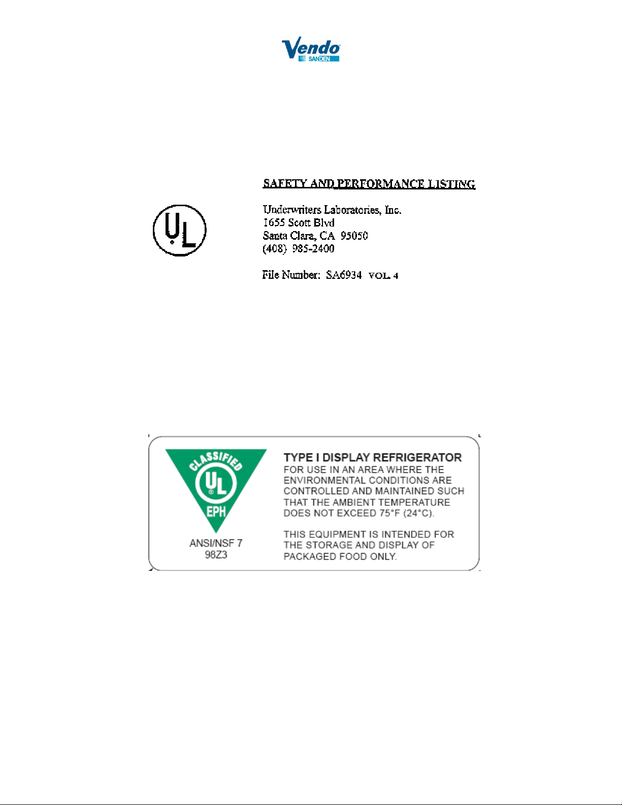
The RD-2 and RD-8 refrigerated display showcase units have been safety and performance-test approved by
various safety regulatory testing agencies. In the course of new installations or periodic inspections, reference to
agency approvals may be required. Following are the regulatory agency file numbers:
2
Page 3
CONTENTS
MAIN COMPONENTS AND DIMENSIONS……………………….4
SPECIFICATIONS…………………………………………………...5
INITIAL SET-UP
Cabinet Set-up…………………………………………………6-10
Cabinet Electrical wiring……………………………………... 11
Shelf & Accessory Installation……………………………….. 11
START-UP & OPERATING INFORMATION
Start-up Information and Performance Evaluation……………12
Operating Guidelines………………………………………….12
COOLING AIRFLOW PATTERN…………………………………..13
GENERAL MAINTENANCE
Cleaning the Honeycomb……………………………………..14
Cleaning the Bottom of the Inner Box & the Drain. …………14
Cleaning the Cabinet………………………………………….14
Lighting ………………………………………………………14
PRECAUTIONS
Storing the Cabinet…………………………………………...15
TROUBLE SHOOTING……………………………………………..15
WIRING DIAGRAM…………………………………………….......16
WARRANTY ACTIVATION SHEET………………………………18-19
3
Page 4
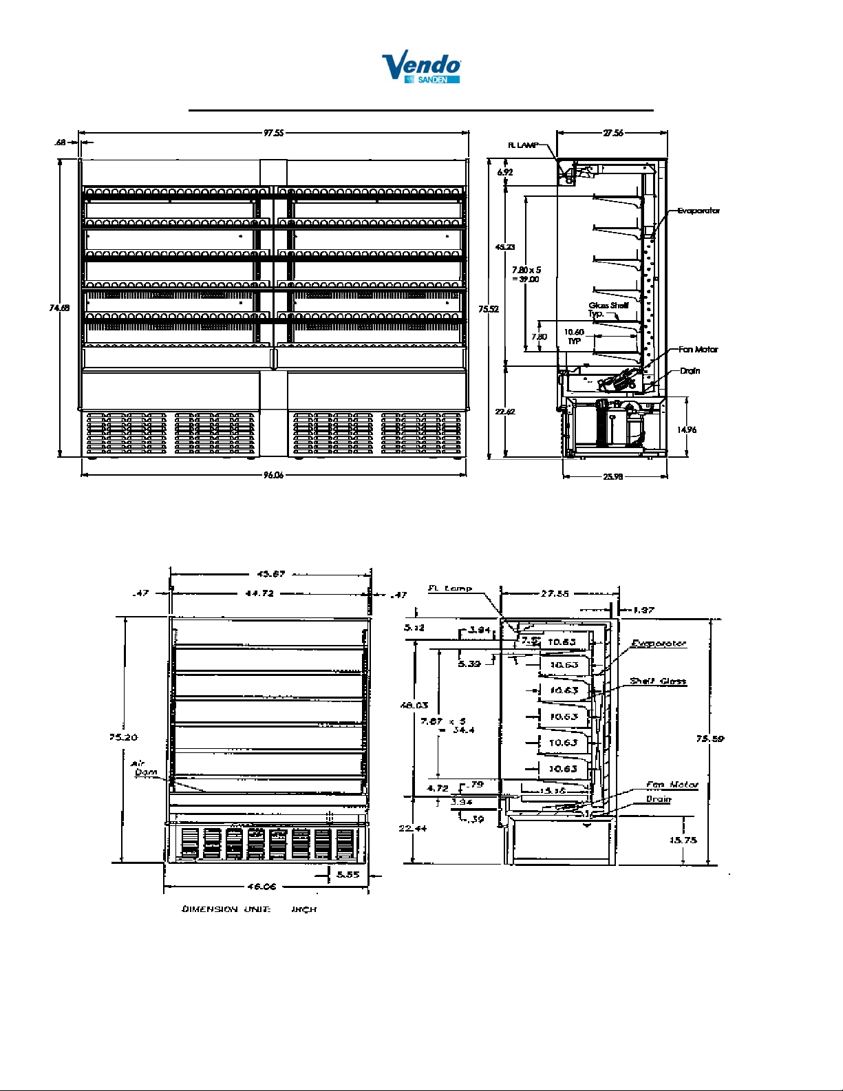
MAIN COMPONENTS AND DIMENSIONS
RD-8
RD-2
4
Page 5
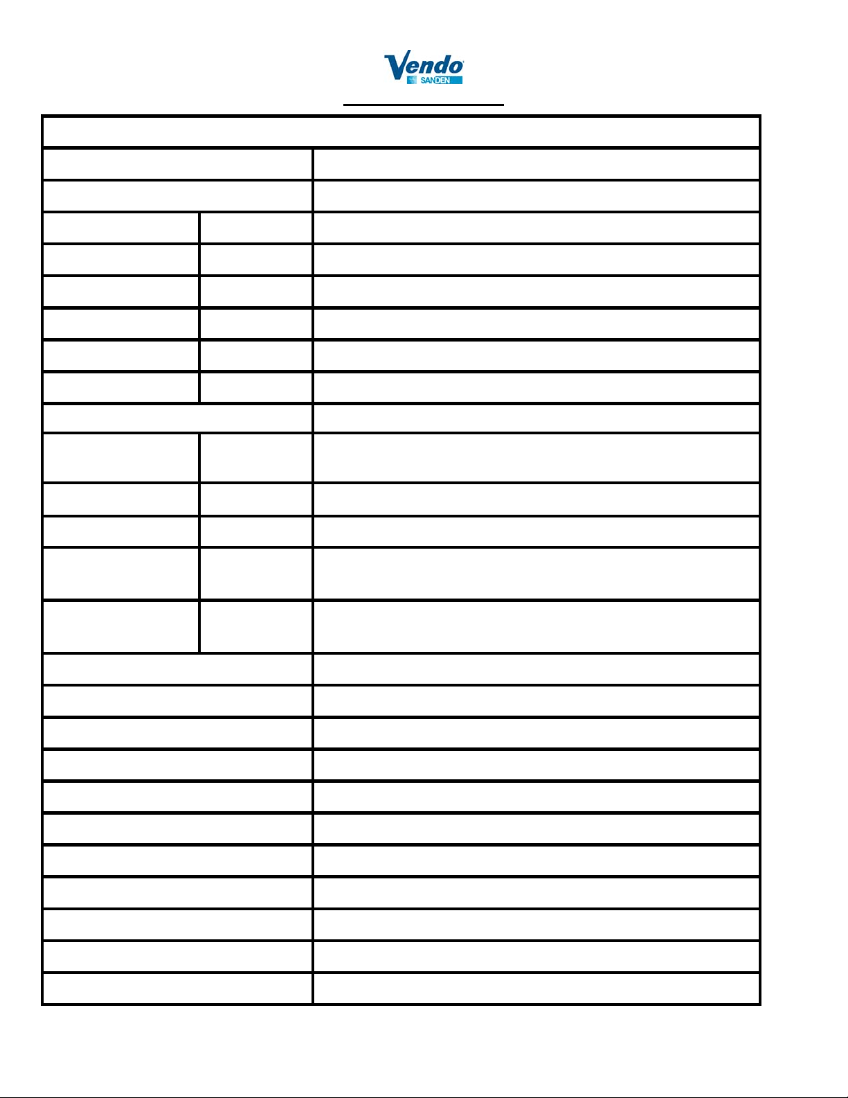
SPECIFICATIONS
MODEL RD-2 AND RD-8
Product Temperature Below 40°F
Environmental Conditions 75°F, 55% relative humidity, Maximum air velocity =60 ft/min
External Dimensions Height 75.52”
Width 45.67” for RD-2 / 97.55” for RD-8
Depth 27.56"
Structure Outer Box Glass & baked acrylic resin finish on electrolytic zinc-coated steel.
Inner Box Baked acrylic resin finish on electrolytic zinc-coated steel.
Insulation Rigid polyurethane foam
Shelves (6 Total) Depth = 10.6”
Electrical Parts
115V 60Hz 1-Phase
Lighting 25 Watt, 0.39 Amp
12Vac Transformer Controller 12VAC 16A 2HP 250VAC
Electrical Parts
230V 60Hz
Input voltage
210-253V 1-Phase
Refrigerant HFC-404A (charged 3.0 lbs)
Evaporator Fin-tube type
Expansion Valve Internally Equalized Automatic Thermal-expansion Valve.
Solenoid Valve Hermetic Direct Acting Type Solenoid Valve for Refrigeration
Thermostat Electronic- Defrost on Demand (10 ~ 30 minutes, every 2 hours)
Drain-pipe Dimension 1.25” copper tube
Evaporator
Fan Motor
Compressor(s) 1.25 HP, 10 Amp left side
6 Watt, 3 each
10 Amp right side
Buck and Boost Transformer required when voltage is below
210VAC or above 253VAC
Internal Volume 26.4 ft3 for RD-2 / 53.3 ft3 for RD-8
Weight 560 lbs. for RD-2 / 900 lbs. for RD-8
Noise Less than 65 DB at 3.3 ft.
Agency Approvals UL, UL NSF
Top Shelf Tilt 7.5°
NOTE: The manufacturer reserves the right to make product improvements and change specifications without notice
5
Page 6
INITIAL SET-UP
The Model RD-8 and RD-2 Refrigerated Showcase, when properly installed and maintained, is designed to
provide years of trouble-free operation. This Operation Manual contains information necessary for proper
installation, maintenance and cleaning of the unit.
It is the responsibility of the installer to ensure the unit is installed and working properly. The following
instructions provide step-by-step set-up, piping, condensate drain connections, wiring, start-up, performance
and maintenance guidelines.
Following installation, please review, fill out and sign form for activation of warranty within 5 days of
installation. FAX: 1800-561-5684 or email: [email protected]
CABINET SET-UP
Step 1: Choose a location for your new refrigerated display case. Avoid placing the cabinet near equipment that
releases heat. Avoid direct sunlight. To protect all electrical parts, do not place the cabinet where it
will be subjected to rain, splashed liquid, or excessive humidity. Place unit at least 12” away from the
rear wall.
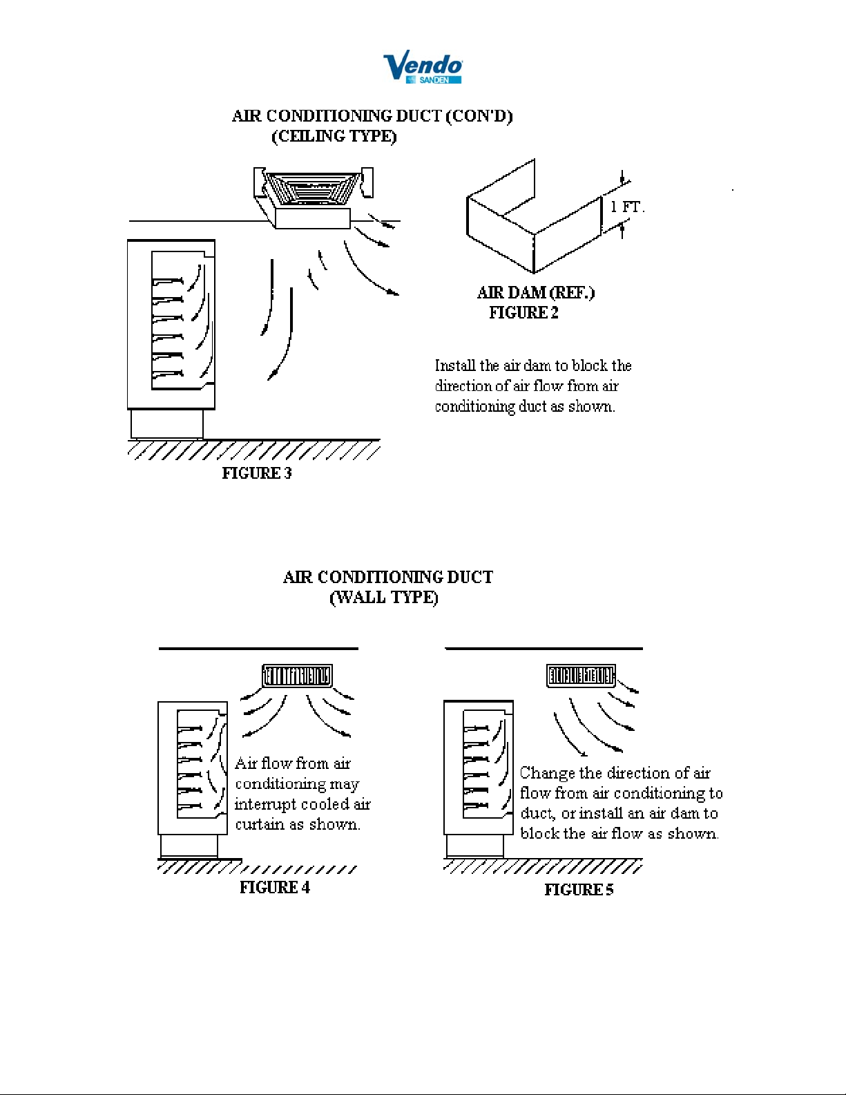
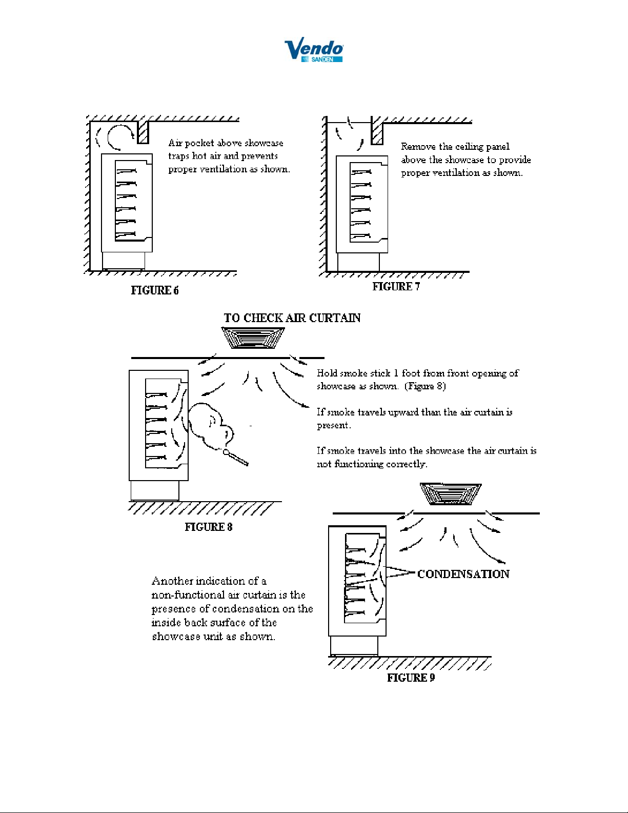
Step 2: Check the airflow around the cabinet, since strong airflow may displace the cooled air in the display
case. Place the cabinet where the airflow speed is less than 60 ft/min. Also, avoid areas subject to
strong winds or cigarette smoke (see figures 1-9).
6
Page 7
7
Page 8
8
Page 9
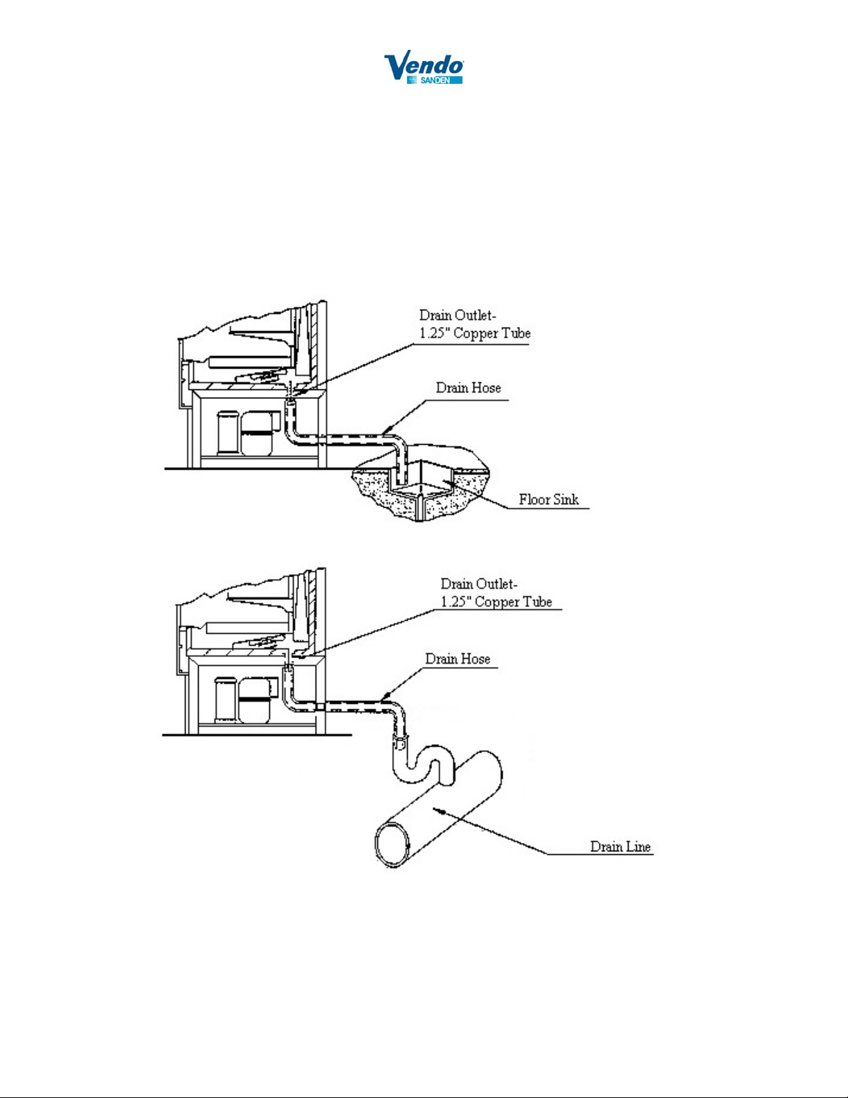
CONDENSATE DRAIN CONNECTION (PREFERRED METHOD)
Install the appropriate condensate drain line between the 1 ¼” copper tube outlet to either a floor sink, a drain
line or other, allowing a code required air gap.
9
Page 10
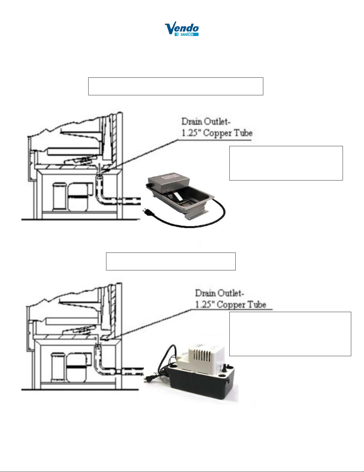
CONDENSATE REMOVAL METHODS (ALTERNATE)
HEATED CONDENSATE PAN
Heated condensate pan, when used, is
recommended to be placed behind the
unit and not inside the compressor
compartment.
CONDENSATE PUMP
Condensate pumps, when used, can be
placed inside the compressor
compartment or behind the unit with the
outlet connected to the nearest drain.
SVA Part Number: 1231359
10
Page 11
CABINET ELECTRICAL WIRING
Step 1: Ensure proper voltage input, minimum 210VAC 60Hz maximum 253VAC 60Hz.
If voltage is below the 210VAC or above 253VAC, a BUCK and BOOST transformer is required.
Step 2: Remove the lower-rear and left-side compressor access panel.
Step 3: Remove the left-side junction-box panel and locate the electrical wiring diagram on
the inside of the panel.
Step 4: Install permanently connected field wiring to the 230V/ 60Hz/ 1 Phase (4-wire) compressor circuit.
The pigtail wires are provided. See the circuit amperage ratings located on the unit nameplate.
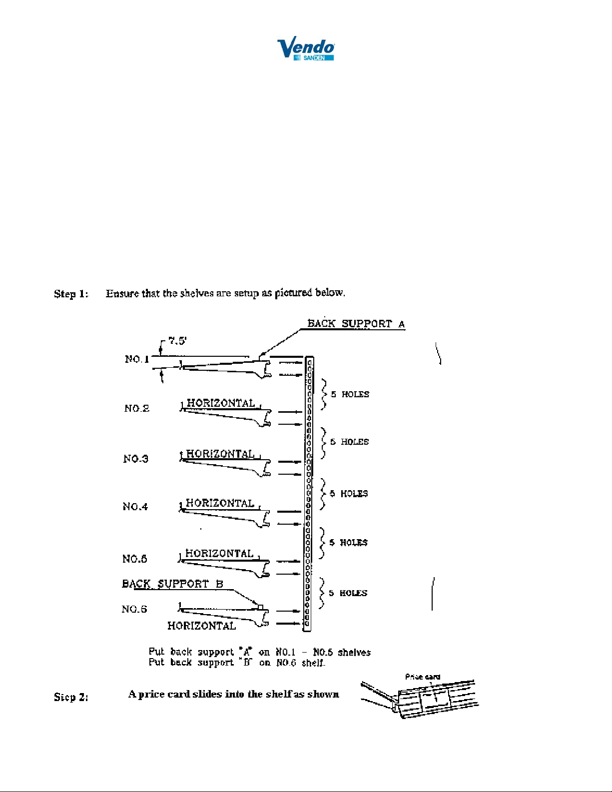
SHELF & ACCESSORY INSTALLATION
11
Page 12
START-UP & OPERATING INFORMATION
START-UP INFORMATION AND PERFORMANCE EVALUATION
Step 1: Open the front panel and flip the toggle switch to the “ON” position for both left and right side unit.
Both the condensing unit, and the evaporator fans should operate, and the fluorescent lighting should
turn on.
Step 2: While the condensing unit and evaporator fans are running, verify that there is a flow of cold air from
the honeycomb, at the top of the cabinet for each left and right side unit.
Step 3: Observing the controller in the upper-left corner, monitor the cabinet temperature, and verify that both
left and right side unit cools to 40°F within 20-30 minutes.
Step 4: Continue to monitor temperature performance through the complete run cycle, until the system enters
the defrost cycle. The defrost cycle (condensing unit shutdown) is programmed to run for 10 ~ 30
minutes every two hours.
Step 5: Verify that all unit access-cover panels have been replaced, and the cabinet is ready to be loaded by
store personnel.
OPERATING GUIDELINES
1. For best results, pre-cool all product before stocking the display case.
2. Stock products only after the cabinet is cooled.
3. When loading the cabinet, do not place merchandise outside of the shaded area.
4. Allow at least 1” between the upper surface of the displayed product and the shelf directly above it.
5. Do not overload product. Improper loading of merchandise may result in refrigeration inefficiency.
6. Do not remove the glass side panels during operation.
7. Do not stock the shelves with all bottles or cans. Hard or heavy merchandises should not be loaded on
the glass shelves.
12
Page 13
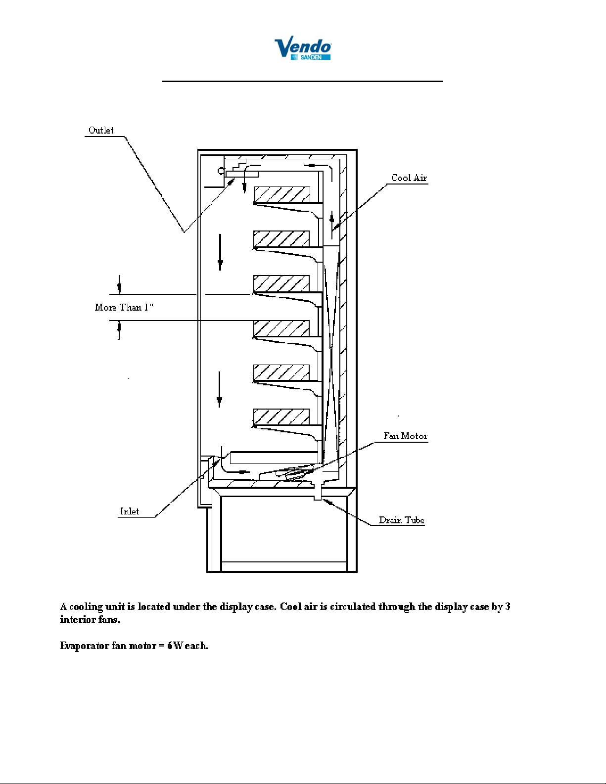
COOLING AIRFLOW PATTERN
13
Page 14
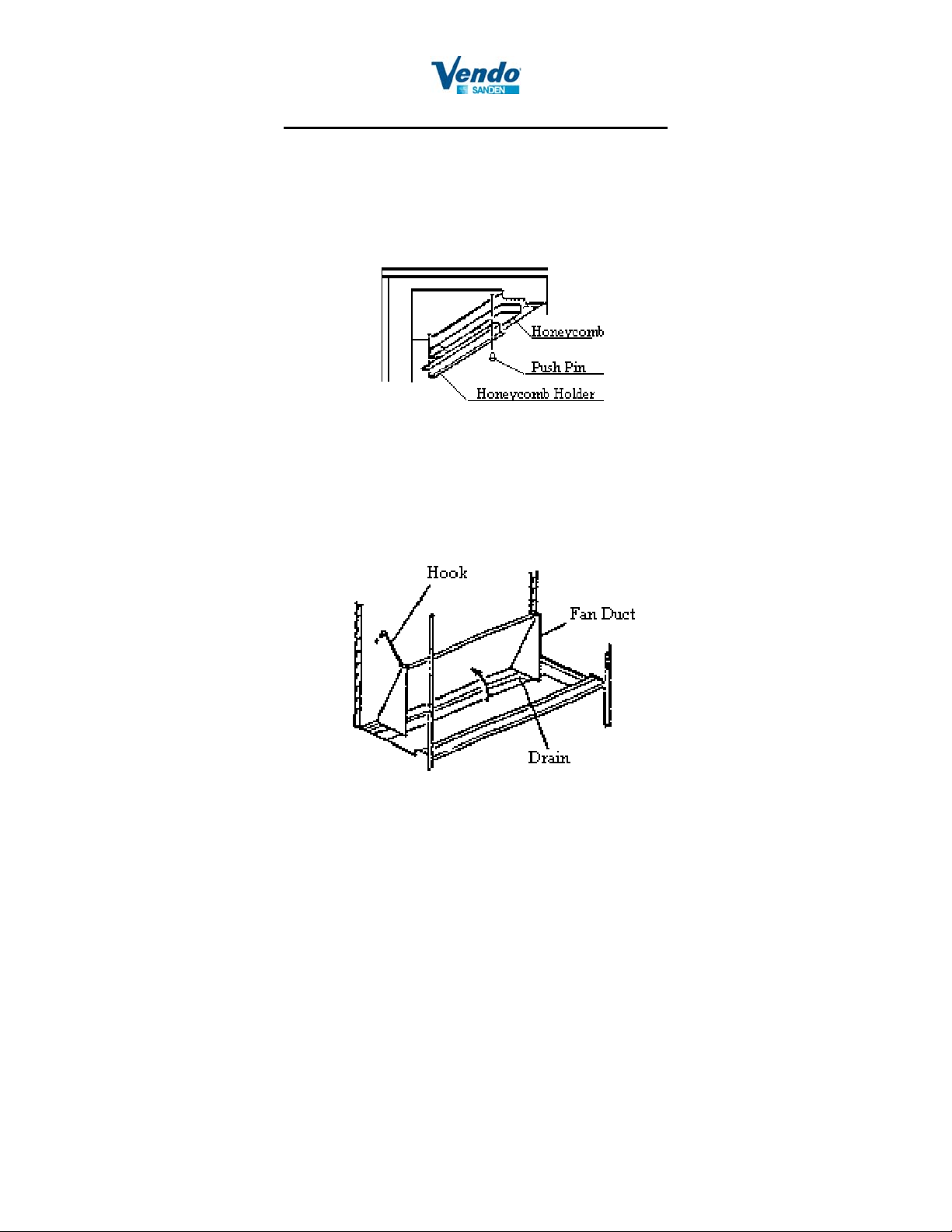
GENERAL MAINTENANCE
CLEANING THE HONEYCOMB
In order to maintain peak operating performance, remove the honeycomb (as shown below) and rinse it with
clean water to remove dust. Under normal conditions, inspect and clean every 30 days.
CLEANING THE BOTTOM OF THE INNER BOX & DRAIN
Lift the fan duct, as shown below, and clean the bottom of the inner box with a mild detergent and a soft, damp
cloth. Check the drain hole for proper water flow and remove any blockage. Rinse with clean water.
CLEANING THE CABINET
To clean the cabinet and shelves, use a mild detergent and a soft, damp cloth. Rinse with clean water. Do not
use paint thinner, laundry detergent, or harsh chemicals.
LIGHTING
Power must be turned OFF prior to servicing fluorescent bulbs. Failure to switch power OFF will
damage the ballast.
Replace inoperable fluorescent lights.
14
Page 15
PRECAUTIONS
CAUTION: Do not operate the unit with the access panels removed.
STORING THE CABINET
Step 1: Disconnect the unit from its power source.
Step 1: Wipe the interior of the cabinet with a damp cloth.
Step 1: Polish the interior of the cabinet with a dry cloth.
Step 1: Store the unit in a clean, dry place. Do not choose a location where the unit will be exposed to direct
sunlight, high temperature, or high humidity.
TROUBLE SHOOTING
Before calling your serviceman, please make these simple checks:
If the unit is not operating:
1. Is the cabinet plugged in?
2. Is there a main-power failure?
3. Is there a blown fuse?
4. Has the refrigeration unit cycled off, because it is at the designated operating temperature?
Note: The evaporator fan motors run continuously and do not cycle with the refrigeration unit.
If the fluorescent light is off:
1. Is the fluorescent-light tube properly connected to the socket?
2. Does the fluorescent light need to be changed?
If the cabinet temperature is too warm:
1. Is the controler set correctly?
2. Is the cabinet located in direct sunlight?
3. Is the cabinet located in a strong air-flow path?
4. Is the distance between the upper surface of the displayed merchandise and the shelf directly above it at
least 1”?
5. Is the air temperature around the cabinet above 75°F?
Reasons for high pressure trips:
1. Overcharge or Non-condensibles.
2. Dirty condenser.
3. TXV sensor bulb loose or powerhead defective.
4. TXV sensor bulb poorly insulated.
REFER TO THE ENVIRONMENTAL CONSIDERATIONS, ON PAGES 5 THROUGH 7,
THAT WILL AFFECT COOLING PERFORMANCE.
15
Page 16
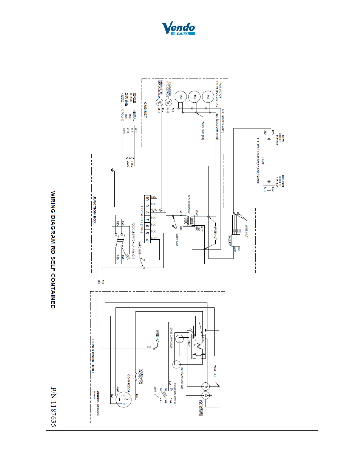
Wiring Diagram RD Self Contained
16
Page 17
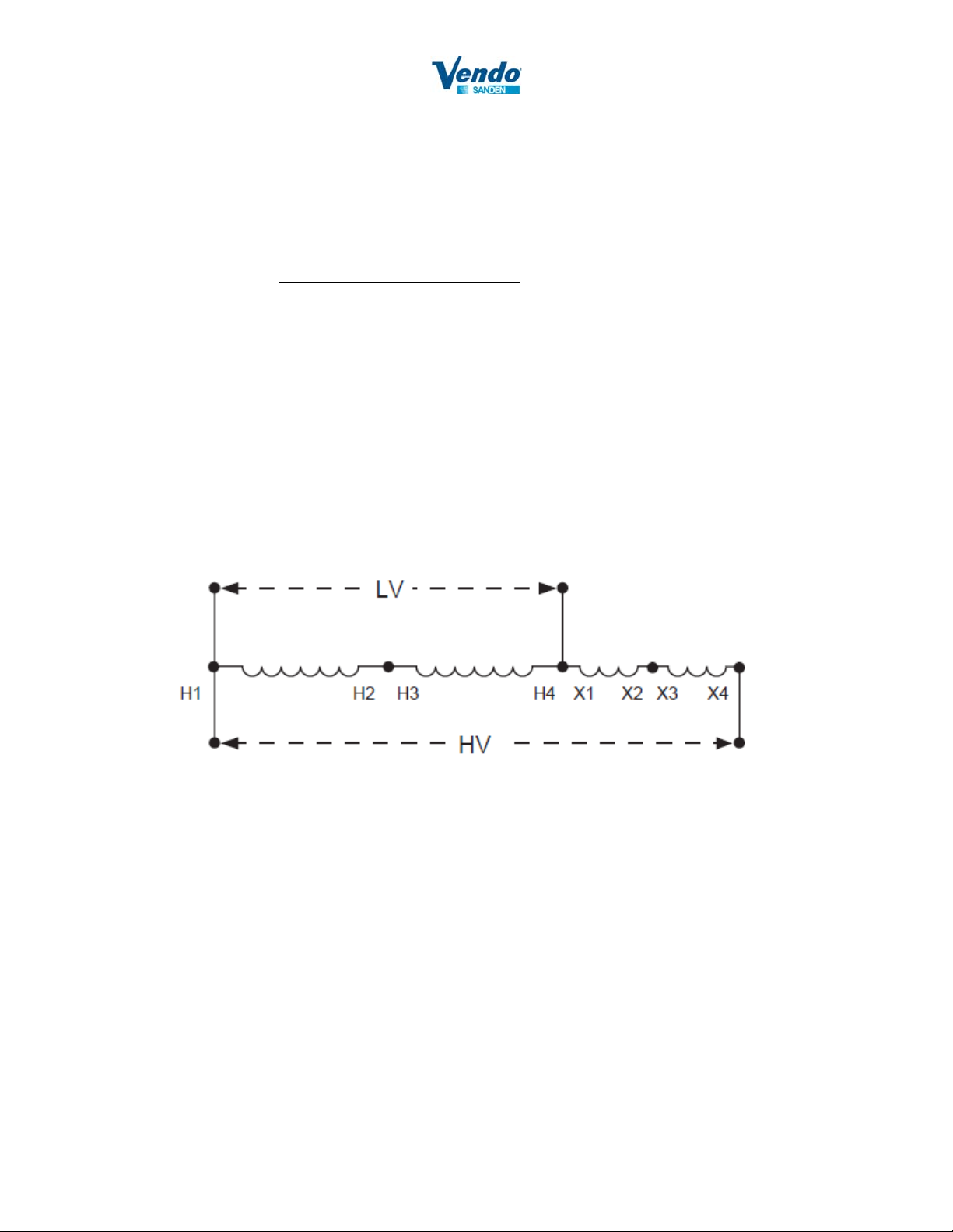
Wiring Diagram (buck and boost model number Square D 500SV43B)
Measure line voltage; if line voltage is less than 210V, use buck and boost per instructions below.
1. Connect line voltage supply (LV) side to H1 and H4/X1 terminal.
2. Measure output voltage between terminals H1 and X4. Do not connect to unit if voltage exceeds
253V.
3. Connect load side or unit side to H1 and X4 terminals.
17
Page 18
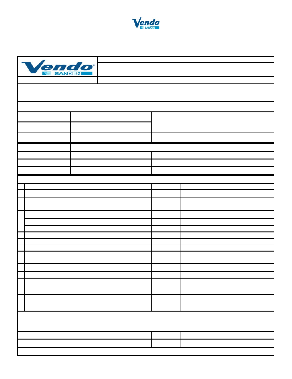
Warranty Activation
Form No.: QF-PE-0047-C
Date Issued: 4/20/2010
PART NUMBER: 1189633A
Document Name:
To activate the warranty for this machine the following information must be returned to
SandenVendo's Customer Service Department within 5 days of Installation
<Contact Information> FAX : 1-800-561-5684 or e-mail : [email protected]
Customer Store Addres s :
Store No. & Store Name
Date of Installation : Installer's Name
RD8 Warranty Activation and Checklist
Model Name :
Serial No. : Cabinet : Remote Condenser :
Asset Management No. : Cabinet : Remote Condenser :
ShockWatch State (Color) at Rear :
RD2 RD-8 (Self Contain) RD3 RD-8 REMOTE
at Front :
Installation: Manuals can be obtained at www.vendoco.com (http://www.vendoco.com/Documents.aspx?ID=8)
Check Items
Inspect for damages on cabinet.
1
When you joined the two halves together, did you follow the
2 Yes No
"RD8 Instructions" (document #1142811) ?
Refrigeration piping Size (Outer Diameter)
3
- Remote Condenser Dischar ge Line (actual) : 1/2"
- Remote Condenser Liquid Line (ac tual) : 3/8"
Refrigerant Line Length (actua l ) Max. Length is 45 ft.
4 ft.
Refrigerant Line Vertical Rise Max. Vertical Rise is 15 ft.
5 ft.
Was the Oil Return considered in Refrigerant Line set ?
6 Yes No
Pressurized line set with nitrogen prior to opening service
7
valve, leak test and evacuate.
Vacuum remote line set to 20 0micron.
8
How much additional refrigerant R404a was added (Remote)
9
If Remote Air-coole d Conde ns e r was installed higher than 15
ft. above the Cabinet, is the Discharge Pipe higher than
10 Yes No
Remote Condenser ? Inverted "P trap"
When you installed "Remote Condenser, did you follow
"REMOTE CONDENSER INSTALLATION" written in the
11 Yes No
Operation Manual 1160915?
Notes :
Result Note
in.
in.
If the result is NG, please write down the detail in the Note column. Date :
It is preferable that there is a photo of NG part.
18
Signature :
Page 19
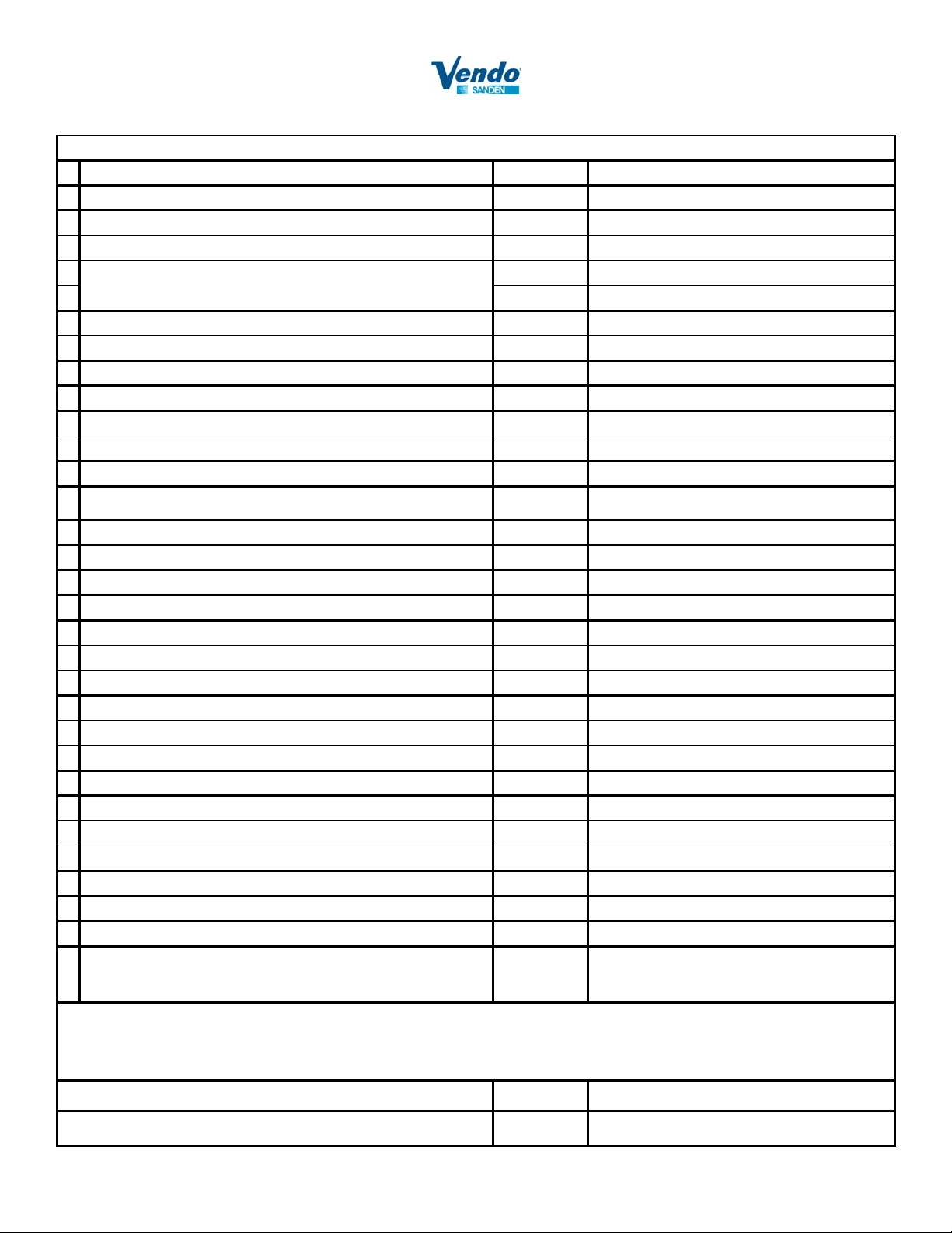
Cabinet and Remote Condenser
Check Items
Input Voltage to Case 208-253VAC 60Hz
1
Left side case input voltage:
Right side case input voltage:
If Voltage is below 208V AC, is a Buck Boost Transformer
installed, what is voltage input with transformer:
Environment Condition
2
- Outside Ambient Temperature of Store :
- Inside Ambient Temperature of Store :
Temeprature inside Cabinet after pull down
3
Temperature in the Cabinet : Left side
Temperature in the Cabinet : Right side
What is the compressor superheat ; range 15-25F
4 °F
Is a Head master valve added for cold weather environment?
5
LAC-4-210
Number of Shelves excluded bo ttom plate :
6 Shelves
Lighting
7
- Lighting of FL Lamp :
- No Flickering of FL Lamp :
No Abnormal Noise
8
- Cabinet :
- Remote Condenser :
No Abnormal Vibration
9
- Cabinet :
- Remote Condenser :
- Refrigerant Line :
No Water Leakage
10
- Cabinet :
- Drain Line :
No Scratch, No Dent & No Deformation on the appearance
11
- Cabinet :
- Remote Condenser :
When you set-up, did you follow "CABINET SET-UP" and
"CONDENSATE DRAIN CONNECTION" written in the Operation
12 Yes No
Manual 1160915 ?
Notes :
Result Note
V
V
Yes No
V
OK NG
OK NG
OK NG
OK NG
OK NG
OK NG
OK NG
OK NG
OK NG
OK NG
OK NG
°F
°F
°F
°F
If the result is NG, please write down the detail in the Note column. Date :
It is preferable that there is a photo of NG part. Signature :
19
 Loading...