


PARTS AND SERVICE
MANUAL
P/N: 1122182
REV B: 09/2003
TCDP-1

V-MAX DR PEPPER TABLE OF CONTENTS
SAFETY SECTION ..................................................................................... |
Pages S-1 - S-18 |
A COMMITMENT TO SAFETY ................................................................... |
Page S-2 |
VENDOR INSTALLATION .......................................................................... |
Pages S-3 - S-6 |
ELECTRICAL HAZARDS ............................................................................ |
Pages S-7 - S-8 |
MECHANICAL HAZARDS........................................................................... |
Page S-9 |
REFRIGERATION HAZARDS..................................................................... |
Page S-10 |
SUBSTITUTIONS AND MODIFICATIONS.................................................. |
Pages S-11 - S-12 |
CONSUMER SAFETY WARNING .............................................................. |
Page S-13 |
GAS ISLAND VENDOR INSTALLATION PROTOCOL............................... |
Page S-14 |
MOUNTING TO PEDESTAL ....................................................................... |
Page S-15 |
PARTS, SALES, AND SERVICE CENTERS OF VENDO/SANDEN CO. ... |
Pages S-16 - S-17 |
GENERAL INFORMATION......................................................................... |
Pages G1 - G12 |
GENERAL INFORMATION ......................................................................... |
Page G-2 |
INITIAL SET-UP ......................................................................................... |
Pages G-3 - G-4 |
LABEL INSTALLATION............................................................................... |
Page G-5 |
ALIGNMENT CHECKS ............................................................................... |
Page G-6 |
LOADING INSTRUCTIONS ........................................................................ |
Page G-7 |
VEND MECHANISM PARTS DESCRIPTION ............................................. |
Pages G-8 - G-9 |
VEND CYCLE ............................................................................................. |
Pages G-10 - G-11 |
PROGRAMMING SECTION ....................................................................... |
Pages PC-1 - PC-22 |
9.1 PROGRAMMING .................................................................................. |
Pages PC-2 - PC-4 |
SET-UP AND CODE DESCRIPTION.......................................................... |
Pages PC-5 - PC-17 |
9.1 WIRING DIAGRAMS............................................................................. |
Pages PC-19 - PC-22 |
CABINET PARTS SECTION ...................................................................... |
Pages C-1 - C-18 |
READING A PARTS LIST ........................................................................... |
Page C-2 |
HARDWARE LIST....................................................................................... |
Pages C-3 - C-4 |
INNER DOOR ASSEMBLY ......................................................................... |
Pages C-6 - C-7 |
CABINET ASSEMBLY ................................................................................ |
Pages C-8 - C-9 |
STACK ASSEMBLY .................................................................................... |
Pages C-10 - C-13 |
REFRIGERATION ASSEMBLY................................................................... |
Pages C-14 - C-15 |
AIR DAM ASSEMBLY ................................................................................. |
Pages C-16 - C-17 |
V-MAX DR PEPPER PARTS SECTION..................................................... |
Pages DP-1 - DP-14 |
MAIN DOOR................................................................................................ |
Pages DP-2 - DP-5 |
LIGHTING ................................................................................................... |
Pages DP-6 - DP-9 |
SELECTION PANEL ................................................................................... |
Pages DP-10 - DP-11 |
LOCK ASSEMBLY ...................................................................................... |
Pages DP-12 - DP-13 |
GAS ISLAND VENDOR PARTS SECTION................................................ |
Pages GIV-1 – GIV-16 |
OUTER DOOR ............................................................................................ |
Pages GIV-2 – GIV-5 |
LOCK ASSEMBLY ...................................................................................... |
Pages GIV-6 – GIV-7 |
COIN INSERT ............................................................................................. |
Pages GIV-8 – GIV-9 |
SELECTION PANEL ................................................................................... |
Pages GIV-10 – GIV-11 |
MOUNTING PEDESTAL ASSEMBLY......................................................... |
Pages GIV-12 – GIV-13 |
SWITCH MOUNT ASSEMBLY.................................................................... |
Pages GIV-14 – GIV-15 |
TCDP-2

MAINTENANCE.......................................................................................... |
Pages M-1 - M-10 |
REFRIGERATION OPERATION................................................................. |
Pages M-2 - M-3 |
REFRIGERATION PARTS DESCRIPTION ................................................ |
Pages M-4 - M-6 |
WIRING DIAGRAMS................................................................................... |
Pages M-7 - M-9 |
TROUBLESHOOTING................................................................................ |
Pages T-1 - T-9 |
VENDO WARRANTY .................................................................................. |
Pages T-2 - T-3 |
TROUBLESHOOTING GUIDE.................................................................... |
Pages T-4 - T-8 |
TCDP-3

SAFETY SECTION
S-1 |
09/2003 |

A COMMITMENT TO SAFETY
The Vendo Company is committed to safety in every aspect of our product design. Vendo is committed to alerting every user to the possible dangers involved in improper handling or maintenance of our equipment. The servicing of any electrical or mechanical device involves potential hazards, both to those servicing the equipment and to users of the equipment. These hazards can arise because of improper maintenance techniques. The purpose of this manual is to alert everyone servicing Vendo equipment of potentially hazardous areas, and to provide basic safety guidelines for proper maintenance.
This manual contains various warnings that should be carefully read to minimize the risk of personal injury to service personnel. This manual also contains service information to insure that proper methods are followed to avoid damaging the vendor or making it unsafe.
It is also important to understand these warnings are not exhaustive. Vendo could not possibly know, evaluate, or advise of all of the conceivable ways in which service might be done. Nor can Vendo predict all of the possible hazardous results. The safety precautions outlined in this manual provide the basis for an effective safety program. Use these precautions, along with the service manual, when installing or servicing the vendor.
We strongly recommend a similar commitment to safety by every servicing organization. Only properly-trained personnel should have access to the interior of the machine.
This will minimize the potential hazards that are inherent in electrical and mechanical devices. Vendo has no control over the machine once it leaves the premises. It is the owner or lessor’s responsibility to maintain the vendor in a safe condition. See Section I of this manual for proper installation procedures and refer to the appropriate service manual for recommended maintenance procedures. If you have any questions, please contact the
Technical Services Department of the Vendo office nearest you.
SAFETY RULES
•Read the Safety Manual before installation or service.
•Test for proper grounding before installing to reduce the risk of electrical shock and fire.
•Turn off power switch or disconnect power cord from wall outlet before servicing or clearing product jams. The vending mechanism can trap and pinch hands.
•Use only fully-trained service technicians for PowerOn servicing.
•Remove any product prior to moving a vendor.
•Use adequate equipment when moving a vendor.
•Always wear eye protection, and protect your hands, face, and body when working near the refrigeration system.
•Use only authorized replacement parts.
•Be aware of inherent dangers in rocking or tipping a vending machine.
•Always turn power off before plugging or unplugging vendor to wall outlet.
S-2 |
09/2003 |

SECTION I: VENDOR INSTALLATION
A.Vendors are large, bulky machines of significant size and weight. Improper handling can result in injury. When moving a vendor, carefully plan the route to be taken and the people and equipment required to accomplish the task safely.
B.Remove all tape, shipping sealant, and Styrofoam from the vendor. Loosen any shipping devices used to secure interior parts during shipping. Remove the wooden shipping base attached to the vendor base by the vendor leveling screws. Make certain the leveling screws are in place and functional.
C.Position the vendor three to four inches (7.6 cm to 10.2 cm) from a well-constructed wall (of a building or otherwise) on a flat, smooth surface.
IMPORTANT: The vendor requires three inches (7.6 cm) of air space from the wall to ensure proper air circulation to cool the refrigeration unit.
D.Adjust the leveling screws to compensate for any irregularities on the floor surface.
Ideally, no adjustment will be necessary and the leveling legs will be flush with the bottom of the vendor. A spirit level is a useful aid to level the vendor. When the vendor is properly leveled the outer door, when opened, will remain stationary. Vendors must be level to ensure proper operation and to maintain stability characteristics. Do not add legs to the vendor.
E.Check the manufacturer’s nameplate on the left or right side of the vendor’s outer door to verify the main power supply requirements of the vendor. Be sure the main power supply matches the requirements of the vendor. To ensure safe operation, plug the vendor only into a properly grounded outlet.
DO NOT USE EXTENSION CORDS.
F.Recommended voltage specs = volts required + amps of circuit.
G.Dedicated 15A service required for 1 machine.
NOTE: Any power supply variance more than + 10% may cause the vendor to malfunction.
*Power outlets must be properly grounded.
*Power outlets must be properly polarized, where applicable.
Test the outlets using the following information.
(Refer to Figure 1 on Page S-4.)
S-3 |
09/2003 |
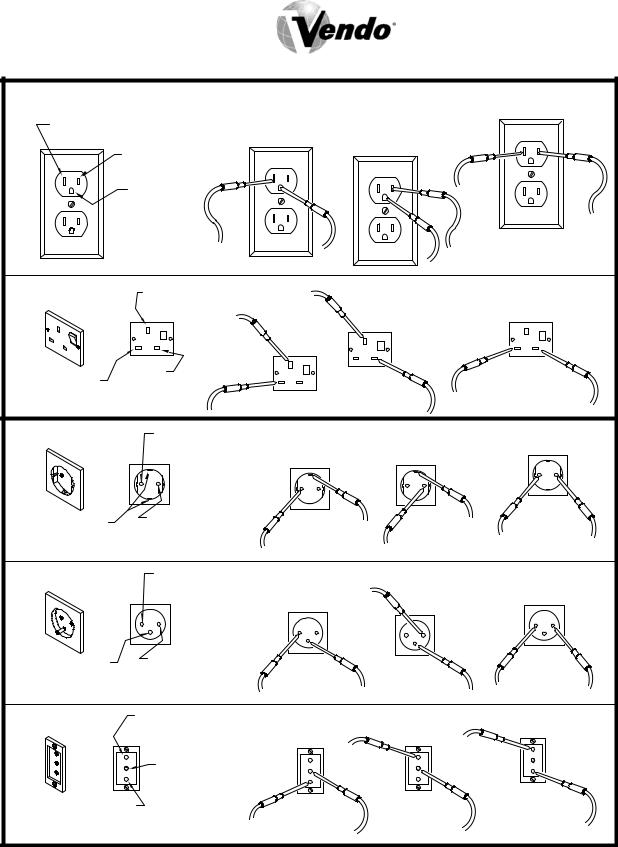
TYPE 1 |
|
|
|
STEP 3 |
|
LARGE SLOT-LINE 2 |
STEP 1 |
|
|
||
NEUTRAL CONTACT (WHITE) 0 - 5 VOLTS |
STEP 2 |
|
|||
|
SMALL SLOT-LINE 1 |
|
|
||
|
|
|
|
||
|
LIVE CONTACT (BLACK) |
|
|
|
|
|
110 VOLTS |
|
|
|
|
|
ROUND SOCKET |
|
|
|
|
|
EARTH CONTACT |
|
|
|
|
|
(GREEN) 0 VOLTS |
|
|
|
|
TYPE 2 |
EARTH CONTACT SLOT |
STEP 2 |
STEP 3 |
||
|
(GREEN AND YELLOW) |
|
|||
|
0 VOLTS |
STEP 1 |
|
|
|
|
|
|
|
||
SLOT |
SLOT |
|
|
|
|
LIVE CONTACT |
|
|
|
||
NEUTRAL CONTACT |
|
|
|
||
(BROWN) 220 VOLTS |
|
|
|
||
(BLUE) 0-5 VOLTS |
|
|
|
||
|
|
|
|
||
TYPE 3 |
POWER CONTACT SOCKET |
|
STEP 3 |
||
NEUTRAL (BLUE) 0-5 VOLTS |
STEP 2 |
||||
|
OR LIVE (BROWN) 220 VOLTS STEP 1 |
|
|||
EARTH CONTACT |
POWER CONTACT |
|
|
|
|
SOCKET |
|
|
|
||
(GREEN AND YELLOW) |
|
|
|
||
0 VOLTS |
NEUTRAL (BLUE) 0-5 VOLTS |
|
|
||
|
OR LIVE (BROWN) 220 |
|
|
|
|
TYPE 4 |
POWER CONTACT SOCKET |
|
|
||
NEUTRAL (BLUE) 0-5 VOLTS |
|
STEP 3 |
|||
|
STEP 2 |
||||
|
OR LIVE (BROWN) 220 VOLTS STEP 1 |
||||
EARTH CONTACT |
POWER CONTACT |
|
|
|
|
SOCKET |
|
|
|
||
(GREEN AND YELLOW) |
|
|
|
||
0 VOLTS |
NEUTRAL (BLUE) 0-5 VOLTS |
|
|
||
|
OR LIVE (BROWN) 220 VOLTS |
|
|
||
TYPE 5 |
POWER CONTACT SOCKET |
STEP 2 |
STEP 3 |
||
NEUTRAL (BLUE) 0-5 VOLTS |
STEP 1 |
||||
|
|
||||
|
OR LIVE (BROWN) 220 VOLTS |
|
|||
|
|
|
|
||
|
EARTH CONTACT SOCKET |
|
|
||
|
(GREEN AND YELLOW) |
|
|
|
|
|
0 VOLTS |
|
|
|
|
POWER CONTACT SOCKET |
|
|
|
||
NEUTRAL (BLUE) 0-5 VOLTS |
|
|
|
|
|
OR LIVE (BROWN) 220 VOLTS |
|
|
|
|
|
FIGURE 1 CHECKING FOR PROPER GROUNDING AND POLARIZATION
S-4 |
09/2003 |
SECTION I: VENDOR INSTALLATION (CONTINUED)
For Type 1 and Type 2 outlets, test for Grounding and Polarization as follows:
1.With a test device (volt meter or test light), connect one probe to the receptacle’s neutral contact and the other to the live contact. The test device should show a reaction.
2.Connect one probe to the receptacle’s earth contact and the other to the live contact. The test device should show a reaction.
For Type 3 through Type 5 outlets, test for Grounding as follows:
1.With a test device (volt meter or test light), determine which of the receptacle’s power contacts is the live contact.
A.Connect one probe to the receptacle’s earth contact.
B.Connect the second probe to the left (or upper) power contact. If a reaction occurs, this is the live power contact. If a reaction does not occur, move the second probe to the right (or lower) contact. A reaction should occur, indicating that this is the live power contact.
2.Connect one probe to the receptacle’s live power contact (as determined in step 1).
Connect the second probe to the other power contact (neutral). The test device should show a reaction.
IF THE ABOVE CONDITIONS ARE NOT MET FOR THE GIVEN OUTLET TYPE, CONTACT A LICENSED ELECTRICIAN AND HAVE THE NECESSARY CORRECTIONS MADE.
S-5 |
09/2003 |
SECTION I: VENDOR INSTALLATION (CONTINUED)
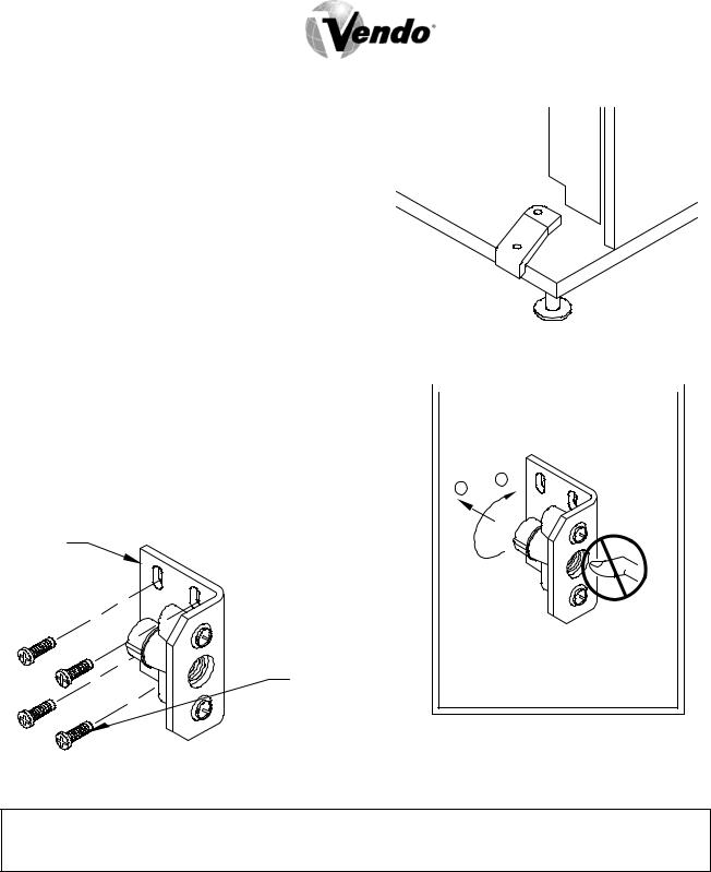
H.Door Support (Figure 2)
The door support is to ensure that the outer door closes squarely to the cabinet. Raising the door can also ensure proper alignment of the door latch.
FIGURE 2
I.Door Latch Alignment (Figure 3)
After any door adjustment, the floating quicker  lock assembly should align itself automatically. DO NOT INSERT OBJECTS
The latch assembly is adjustable. To adjust, |
INTO LOCK CAVITY. |
loosen the latch bracket mounting screws, |
|
raise or lower the latch assembly into position, |
1 |
then tighten the mounting screws. |
2 |
|
LATCH
BRACKET
TO FREE OBJECTS, REMOVE
MOUNTING LOCK CAP AS SHOWN
SCREW
FIGURE 3
WARNING:
KEEP FINGERS AND OTHER OBJECTS OUT OF LOCK CAVITY
NOTE: Refer to the appropriate parts and service manual for detailed instructions, operating principles, and recommended maintenance intervals and procedures.
S-6 |
09/2003 |
SECTION II: ELECTRICAL HAZARDS
GENERAL
Vendo vending machines are provided with the appropriate power supply setting for your area. Some models are equipped with step-down transformers, as required. This enables the vending machine to operate on different main voltages. Refer to Section I. E. for information to determine the main power requirements. Refer to the appropriate service manual for details of step-down transformer operations.
The power sources just mentioned are standard for both household and commercial lighting and appliances. However, careless or improper handling of electrical circuits can result in injury or death. Anyone installing, repairing, loading, opening, or otherwise servicing a vending machine should be alerted to this point. Apply all of the normal precautions observed in handling electrical circuits, such as:
•Refrigeration servicing to be performed by qualified personnel only.
•Unplug the vendor or move power switch to off position before servicing or clearing product jams.
•Replace electrical cords if there is any evidence of fraying or other damage.
•Keep all protective covers and ground wires in place.
•Plug equipment into outlets that are properly grounded and polarized (where applicable), and protected with fuses or circuit breakers.
•All electrical connections must be dry and free of moisture before applying power.
A. Grounding Systems
Vendo vending machines are provided with the appropriate service cord for the power supply in your area. The service cord will connect to the matching electrical outlet. Always ensure that the outlet to be used is properly grounded before plugging in the vendor. (See pages S-3 through S-5.)
WARNING:
ALWAYS TEST TO VERIFY PROPER GROUNDING PRIOR TO INSTALLATION TO REDUCE THE RISK OF ELECTRICAL SHOCK AND FIRE
The electrical grounding system also includes the bonding of all metal components within the vendor. This involves a system of bonding wires identified by green or green and yellow marking. The system uses serrated head screws, lock washers, and star washers to ensure the electrical connection between parts. Maintenance of vending equipment may involve disassembly. Include the above items when reassembling, even if the vending machine may appear to function normally without them. Omitting any of these items can compromise a link in the grounding system. See the appropriate service manual or kit instructions for components and assembly instructions.
S-7 |
09/2003 |

SECTION II: ELECTRICAL HAZARDS (CONTINUED)
B.Servicing with “Power Off”
For maximum safety, unplug the service cord from the wall outlet before opening the vendor door. This will remove power from the equipment and avoid electrical and mechanical hazards. Service personnel should remain aware of possible hazards from hot components even though electrical power is off. See the appropriate sections of this manual for further information.
C.Servicing with “Power On”
Some service situations may require access with the power on. Power on servicing should be performed only by fully-qualified service technicians. Particular caution is required in servicing assemblies that combine electrical power and mechanical movement. Sudden movement (to escape mechanical action) can result in contact with live circuits and vice versa. It is therefore doubly important to maintain maximum clearances from both moving parts and live circuits when servicing.
WARNING:
“POWER-ON” SERVICING SHOULD BE ACCOMPLISHED ONLY BY FULLY-TRAINED PERSONNEL. SUCH SERVICE BY UNQUALIFIED INDIVIDUALS CAN BE DANGEROUS.
Power to lighting and refrigeration system is shut off automatically by the electronic controller when the outer door is opened. Applies to V-Max only.
NOTE: For power-on servicing of the vendor’s lighting system, turn lighting power on by accessing the “LIT” test function of the electronic controller (see programming on inner door). Applies to V-Max only.
For power-on servicing of the vendor’s refrigeration system, turn refrigeration power on by accessing the “CNPR” test function of the electronic controller (see programming on inner door). Applies to V-Max only.
S-8 |
09/2003 |
SECTION III: MECHANICAL |
HAZARDS |
A.Servicing of Moving Parts and Assemblies
When servicing assemblies involving moving parts, use extreme caution!! Keep fingers, hands, loose clothing, hair, tools, or any foreign material clear of entrapment.
As noted before under the electrical hazards section, Power On servicing should only be performed by qualified personnel. Refer to and heed the warnings noted in the electrical hazards section. These warnings refer to the potential hazards associated with electrical power and moving parts. Always maintain maximum clearances from electrical and moving parts.
Always install protective covers and guards when reassembling equipment.
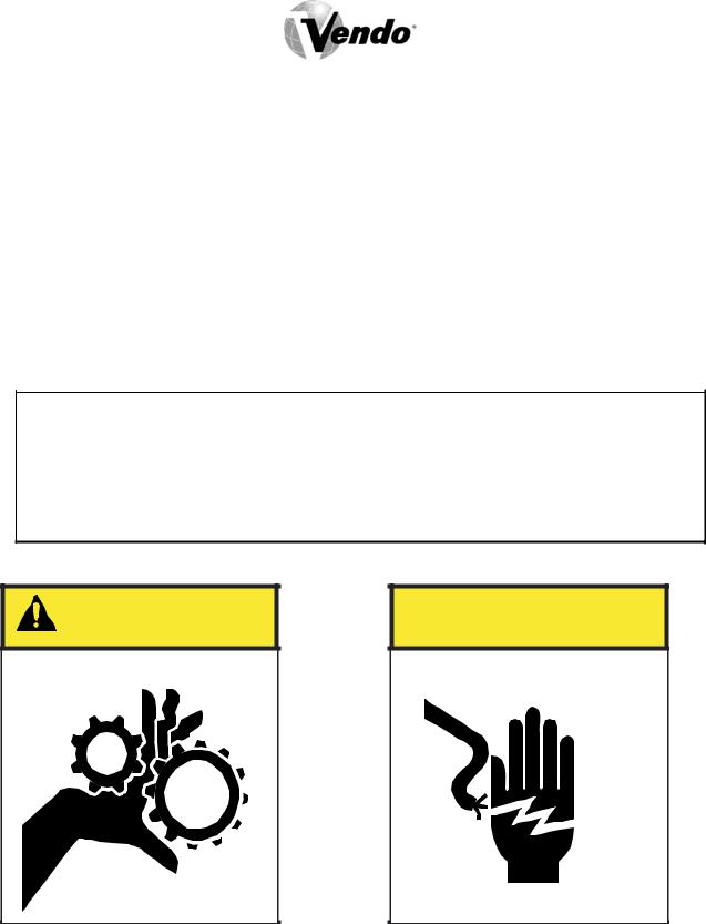
WARNING:
THIS VENDING MACHINE INCLUDES MECHANICAL EQUIPMENT WHICH CAN BE HAZARDOUS IF IMPROPERLY HANDLED OR SERVICED. USE CAUTION AND CONSULT THE VENDO SAFETY MANUAL AND THE VENDO SERVICE MANUAL FOR ADDITIONAL SAFETY INFORMATION.
WARNING |
RISK OF ENTRAPMENT! |
 WARNING
RISK OF SHOCK!
ELECTRICAL!
S-9 |
09/2003 |

SECTION IV: REFRIGERATION HAZARDS
GENERAL
Refrigeration systems involve both electrical power and mechanical action. These systems may present any of the potential dangers shown in the sections on electrical and mechanical hazards contained in this manual. See Sections II and III for further information.
A.Compressed Refrigerant
Refrigeration systems involve the compression and evaporation of gases. The pressures contained represent a potential hazard if suddenly released in confined areas. Caution is required when performing maintenance tests or repairs. All testing of sealed refrigeration systems must be done by trained personnel who are familiar with the systems and pressures involved.
B.Physical Protection
The accidental release of refrigerant gases can result in physical injuries. Always wear protective glasses and protect your hands, face, and body when working near the refrigeration system.
WARNING:
ALWAYS WEAR EYE PROTECTION AND PROTECT YOUR HANDS, FACE, AND BODY WHEN WORKING NEAR THE REFRIGERATION SYSTEM.
SECTION V: TEMPERATURE HAZARDS
GENERAL
Maintenance personnel should be alerted to the potential hazards from hot metal surfaces.
High temperatures may be present throughout the refrigeration system even though electrical power has been removed.
S-10 |
09/2003 |

SECTION VI: SUBSTITUTIONS AND MODIFICATIONS
GENERAL
Unauthorized changes or the substitution of unauthorized parts can compromise the equipment designs. This can result in unsafe conditions for either the service personnel or the equipment users. Always refer to the appropriate parts and service manual for replacement parts and maintenance instructions. If questions arise, contact the Technical Services Department of the Vendo office in your area.
When servicing the vending machine, always reassemble all components to their original location and position. Maintain the correct routing for tubing, electrical wiring, etc. Replace all clamps, brackets, and guides to their original locations. Replace all tubing, sleeving, insulating material, and protective covers to their original condition.
WARNING:
VENDO EQUIPMENT HAS BEEN PROVIDED WITH APPROPRIATE PROTECTIVE DEVICES TO PROTECT AGAINST THE POSSIBILITY OF OVERHEATING AND FIRE AS A RESULT OF EQUIPMENT OR COMPONENT FAILURES. SUBSTITUTION, MODIFICATION, OR BYPASSING OF SUCH PROTECTIVE DEVICES CAN CREATE DANGEROUS CONDITIONS. PROTECTIVE CIRCUITS SHOULD NEVER BE BYPASSED, AND FAILED PROTECTIVE DEVICES MUST BE REPLACED ONLY WITH FACTORY-AUTHORIZED PARTS.
A.Service Cord Replacement
Vendo vending machines are furnished with unique power supply cords. If replacement becomes necessary, consult the appropriate parts and service manual and order the correct replacement cord for the model of vending machine in question. Do not use substitute replacement cords. Only authorized service personnel with appropriate training should replace the vending machine service cord. If a question should arise concerning which service cord to order, contact the Technical Services Department of the Vendo office in your area.
S-11 |
09/2003 |

SECTION VI: SUBSTITUTIONS AND MODIFICATIONS (CONTINUED)
WARNING:
THIS APPLIANCE MUST BE EARTHED.
IMPORTANT!
The wires in the main leads are colored in accordance with the following code:
110v/120v |
220v/240v |
|
Green |
Green and Yellow ............................ |
Earth |
White |
Blue................................................... |
Neutral |
Black |
Brown ............................................... |
Live |
S-12 |
09/2003 |

SECTION VII: CONSUMER |
SAFETY WARNING |
WARNING:
VENDOR CAN BE OVERTURNED IF SUFFICIENT FORCE IS APPLIED, AND MAY RESULT IN SERIOUS INJURY OR DEATH.
GENERAL
There have been incidents, including fatalities, when vending machines have been vandalized by being pulled over in an attempt to obtain free product or money.
To warn of the danger involved in tipping, shaking, or rocking the vending machine, a decal has been designed to be affixed to vending machines. (One such decal is supplied with the vending machine.) Vendo will supply sufficient decals to be placed on all machines, on request. If you have any questions, contact the Technical Services
Department of the Vendo office in your area.
THE FOLLOWING DECAL SHOULD BE PLACED IN A POSITION ON THE VENDOR CONTROL PANEL AT EYE LEVEL.
|
|
|
|
|
|
|
|
|
|
|
|
|
|
|
|
|
|
|
|
|
|
|
|
|
|
|
|
|
|
|
|
|
|
|
|
|
|
|
|
|
|
|
|
|
|
|
|
|
|
|
|
|
|
|
|
|
|
|
|
|
|
|
|
|
|
|
|
|
|
|
|
|
|
|
|
|
|
|
|
|
|
|
|
|
|
|
|
|
|
|
|
|
|
|
|
|
|
|
|
|
|
|
|
|
|
|
|
|
|
|
|
|
|
|
|
|
|
|
|
|
|
|
|
|
|
|
|
|
|
|
|
|
|
|
|
|
|
|
|
|
|
|
|
|
|
|
|
|
|
|
|
|
|
|
|
|
|
|
|
|
|
|
|
|
|
|
|
|
|
|
|
|
|
|
|
|
|
|
|
|
|
|
|
|
|
|
|
|
|
|
|
|
|
|
|
|
|
|
|
|
|
|
|
|
|
|
|
|
|
|
|
|
|
|
|
|
S-13 |
|
|
|
|
|
|
|
|
|
|
|
|
|
|
||
|
|
|
|
|
|
|
|
|
09/2003 |
|||

GAS ISLAND VENDOR INSTALLATION PROTOCOL
Vendo Gas Island Vending Machines have been evaluated by UL (Underwriters Laboratories Inc.®) for placement at service stations which the NFPA (National Fire Protection Association) considers a hazardous location. These vendors must be correctly installed and inspected per the following protocol before they are put into service.
A.Vendor is to be installed in accordance with the National Electrical Code, NFPA 70, Article 514 - Gasoline Dispensing and Service Stations, NFPA 30A - Automotive and Marine Service Station Code, and the Local Authority Having Jurisdiction.
IMPORTANT - Compliance includes direct wiring of the vendor to the voltage source utilizing proper metal conduit and circuit protection.
B.When installed on support base, the vendor can be installed in an 18-inch high Class I, Group D, Division 2 Hazardous Location. Additionally, the vendor must be installed at least 18 inches from any flammable liquid dispensing device.
Vendor support base is to be attached to vendor as shown by view on page S-15. Vendor should be securely bolted in place using ½-inch nominal diameter hardware as a minimum.
C.IMPORTANT: FOR ANY INSTALLATION REQUIRING LEVELING OF THE
VENDOR, IT IS MANDATORY TO OBTAIN APPROVAL OF THE LOCAL AUTHORITY HAVING JURISDICTION. THERE ARE NO EXCEPTIONS.
To level more than 1/8 inch, it is suggested to follow these guidelines:
1.Shimming of one or more mounting points should be done with solid steel, minimum thickness of 1/8 inch. Solid aluminum is acceptable.
2.It is not acceptable to place shims under all (4) mounting points.
3.Shims should be a minimum of 2 ½ inch x 2 ½ inch square or 2 ½ inch diameter.
4.Shim should have a hole, (approximately ½ inch diameter), through the center in the same manner as the GIV pedestal foot.
5.Shim should be protected against corrosion by painting, plating, etc.
6.IMPORTANT: Hold down bolt should be a solid, continuous bolt.
It is MANDATORY that all installations requiring leveling be approved by the LOCAL AUTHORITY HAVING JURISDICTION.
D.Warning - Power tools with arcing and sparking parts, such as electric drills, should not be used in any hazardous locations during the installation of this vendor.
E.The dispensing area shall be in clear view of the attendant at all times, and placing or allowing any obstacle to come between the dispensing area and the attendant control area shall be prohibited.
F.Upon completion of the installation, the Local Fire Marshall, or Authority Having Jurisdiction, must verify the installation complies with the codes shown in Item A.
After authorization, the vendor may be placed into operation.
S-14 |
09/2003 |
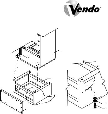
MOUNTING TO PEDESTAL
VENDOR
PEDESTAL |
|
|
FLAT WASHER |
|
LOCK WASHER |
FRONT AND REAR COVER |
HEX BOLT 1/2"-13x1 1/2" |
IMPORTANT - INSTALLATION REQUIREMENTS
Electrical equipment, such as vending machines, installed within a 20-ft. radius of a gasoline dispensing unit must meet safety specifications of the National Electrical
Code, NFPA 70 - Article 514 - Gasoline Dispensing and Service Stations, NFPA 30A - Automobile and Marine Service Station Code, and the Local Authority Having
Jurisdiction. Safety Specifications are:
•The vending machine must be UL Listed for installation near gasoline dispensing equipment.
•The vending machine is UL Listed for use in an 18-inch high Class I, Group D, Division 2 Hazardous Location.
•Installation requires ON-SITE approval of Local Fire Marshall, or Authority Having Jurisdiction.
•The vending machine should be securely bolted in place using ½” nominal diameter hardware as a minimum. Use template provided on pedestal carton for mounting locations. If vendor requires leveling more than 1/8 inch, refer to Page S-14.
•The vending machine must be direct-wired to the voltage source utilizing proper metal conduit and circuit protection.
Note: There are unique safety and approval considerations required for placement of a vendor at the gasoline island which will require a non-standard vending machine. A standard vending machine located at or near the gasoline dispensing area will create unacceptable risks and will not meet safety agency requirements.
S-15 |
09/2003 |

PARTS, SALES, & SERVICE CENTERS OF VENDO/SANDEN COMPANY
AREA |
ADDRESS |
|
|
PHONE NUMBERS |
United States, |
The Vendo Company |
|
Tel: (559) 439-1770 |
|
Canada |
7209 N. Ingram |
|
Fax: (559) 439-2083 |
|
|
Fresno, CA 93650 U.S.A. |
|
Tel: |
(81) 3-3835-1321 |
Japan |
Sanden International Corporation |
|
||
|
31-7 Taito 1-Chome |
|
Fax: |
(81) 3-3833-7096 |
|
Taito-ku |
|
|
|
|
Tokyo 110, Japan |
|
Tel: |
(49) 211-74-039-0 |
Europe, Mid-East, |
Vendo GMBH |
|
||
Africa, Mid-Asia |
Spangerstr. 22, P.O. Box 130940 |
|
Fax: |
(49) 211-7488541 |
|
40599 Dusseldorf |
|
|
|
|
Germany |
|
Tel: 61-2-9791-0999 |
|
Australia, |
Sanden International Pty. Ltd. |
|
||
New Zealand |
54 Allingham St., Condell Park |
|
Fax: 61-2-9791-9029 |
|
|
N.S.W. 2200 |
|
|
|
|
Australia |
|
Tel: 65-482-5500 |
|
Singapore, |
Sanden International (Singapore) Pte., Ltd. |
|
||
Hong Kong, |
Sanden House, 25, Ang Mo Kio St. 65 |
|
Fax: |
65-482-1697 |
Indonesia, |
Singapore 569062 |
|
|
|
Philippines, India |
The Republic of Singapore |
|
Tel: |
886-2-570-6106 |
Taiwan |
Sanden International Taiwan Corp. |
|
||
|
No, 21-6, Sec 1 |
|
Fax: |
886-2-577-1959 |
|
Tun Hwa S. Rd., Taipei, Taiwan |
|
|
|
|
Taiwan, ROC |
|
Tel: |
32-2-268-2595 |
Belgium |
N.V. Vendo Benelux, S.A. |
|
||
|
Industrial Research Park N.O.H. |
|
Fax: |
32-2-268-2862 |
|
13 Font St. Landry |
|
|
|
|
1120 Brussels |
|
|
|
|
Belgium |
|
Tel: |
44-1256-479309 |
England |
Vendhall, Ltd. |
|
||
|
Unit 17, The Basingstoke Enterprise Centre |
|
Fax: |
44-1256-844469 |
|
Westham Lane, Worting Rd, |
|
|
|
|
Basingstoke, Hants RG22, 6NQ |
|
|
|
|
Great Britain |
|
Tel: |
39-142-335111 |
Italy |
Vendo Italy S.p.A. |
|
||
|
Casella Postale 9 |
|
Fax: |
39-142-5623-48 |
|
1-15033 Casale Monferrato |
|
|
|
|
Italy |
|
Tel: 343-474-1555 |
|
Spain |
Vendo Iberia, S.A. |
|
||
|
C/ Sant Ferran No. 92 |
|
Fax: 343-474-1842 |
|
|
Poligono Industrial la Almeda, Sector P-1 |
|
|
|
|
08940 Cornella, (Barcelona), Spain |
|
|
|
S-16 |
09/2003 |
PARTS, SALES, & SERVICE CENTERS OF VENDO/SANDEN COMPANY
FOR LATIN AMERICA
|
|
|
|
|
|
|
|
|
|
AREA |
|
|
ADDRESS |
|
|
PHONE NUMBERS |
|
|
Mexico |
|
Vendo de Mexico |
|
Tel: |
(525) 515-9745 |
||
|
|
|
|
Camino Real de Toluca No. 154 |
|
Fax: |
(525) 277-0111 |
|
|
|
|
|
Col. Bellavista |
|
|
|
|
|
|
|
|
01140 Mexico D.F. Mexico |
|
|
|
|
|
Central America |
|
The Vendo Company |
|
Tel: (559) 439-1770 |
|||
|
|
|
|
7209 N. Ingram |
|
Fax: (559) 439-2083 |
||
|
|
|
|
Fresno, CA 93650 U.S.A. |
|
|
|
|
|
Chile |
|
Pelp Internacional, S.A. |
|
Tel: |
(562) 243-9710 |
||
|
|
|
|
4560 El Rosal |
|
Fax: |
(562) 740-0504 |
|
|
|
|
|
Huechuraba, Santiago, Chile |
|
|
|
|
|
Brazil |
|
Cimaq Industria e Comercio de Maq, |
|
Tel: (55242) 22-2666 |
|||
|
|
|
|
Ltda. |
|
Fax: (55242) 22-3244 |
||
|
|
|
|
Estrada Uniao e Industria, 9.120 Itaipava |
|
|
|
|
|
|
|
|
25730-730 Petropolis |
|
|
|
|
|
|
|
|
Rio de Janeiro, Brazil |
|
|
|
|
|
South America |
|
The Vendo Company |
|
Tel: |
(559) 439-1770 |
||
|
|
|
|
7209 N. Ingram Ave. |
|
Fax: |
(559) 439-2083 |
|
|
|
|
|
Fresno, CA 93650 U.S.A. |
|
|
|
|
|
|
|
|
|
|
|
|
|
S-17 |
09/2003 |

NOTES
S-18 |
09/2003 |

GENERAL INFORMATION
G-1 |
09/2003 |

GENERAL INFORMATION
This manual contains programming, operation, and complete parts and electrical wiring diagrams.
The V-Max controller is a microprocessor which will permit pricing per selection from
0.00 to 99.99. This machine also has space-to-sales programming as well as energy savings modes.
Specifications:
MODEL |
V-MAX 720 |
V-MAX 840 |
V-MAX 576 |
||
SELECTIONS |
10 |
10 |
8 |
||
|
|
|
DIMENSIONS (HEIGHT X WIDTH X DEPTH) |
|
|
CURVED DOOR |
72” x 39 ½ “ x 35” |
79” x 39 ½ “ x 35” |
72” x 32 ½ “ x 34 ¾” |
||
FLAT DOOR |
|
72” x 39 ½” x 32 ½” |
79” x 39 ½” x 32 ½” |
Not Available |
|
SINGLE COLUMNS |
10 |
10 |
8 |
||
CAPACITY |
|
12 oz. CAN*** |
72 |
84 |
72 |
PER |
|
16 oz. GLASS |
30 |
36 |
30 |
COLUMN |
|
20 oz. ** |
32 |
38 |
32 |
SHIPPING |
WEIGHT |
685 Ibs |
750 Ibs |
640 Ibs |
|
OPERATION VOLTAGE |
115v 60 Hz. |
115v 60Hz. |
115v 60Hz. |
||
AMP. RATING |
10 |
10 |
10 |
||
REFRIGERATION |
115v 60Hz. |
115v 60Hz. |
115v 60Hz. |
||
VOLTAGE |
|
|
|
||
*Dimensions and shipping weight will vary slightly due to manufacturing tolerances, shipping boards and whether or not coinage is installed.
** 20 oz. PET capacity may vary based on the shape and size of the bottle.
***12 oz. can capacities are listed using a 4-deep set up.
G-2 |
09/2003 |

INITIAL SET-UP
A. UNPACKING
Remove all plastic film, cardboard and tape from the outside of the vendor. Loosen any shipping devices used to secure interior parts during shipment (backspacer, shims or spacers).
To remove shipping boards from base, raise vendor on a well-stabilized lifting device. Remove the leveling bolts which hold the boards in place and remove the boards. Replace bolts to equal heights in the threaded holes.
Another method to remove shipping boards is to split the boards apart. Using a pinch bar or a heavy screwdriver and hammer, insert tool into the slots and force the boards apart.
B. POSITIONING
IMPORTANT: PLACE THE VENDOR IN DESIRED LOCATION AT LEAST THREE TO FOUR INCHES (7.6CM TO 10.2CM) AWAY FROM ANY REAR OBSTRUCTION. This is for proper air flow through the refrigeration compartment. The refrigeration system requires front to rear air circulation for proper operation.
C. POWER SUPPLY CONNECTION
CAUTION: DO NOT USE AN EXTENSION CORD!
The vendor’s power requirements will vary depending upon the country it was purchased for. To verify the power requirements of the vendor, check the serial plate located on the hinged side of the outer door (see Figure 4 on page G-4). The power requirements are listed on the serial plate.
To insure safe operation of the vendor, the vendor’s power supply must be a properly grounded and polarized outlet. Before plugging the vendor into the outlet, test the outlet to confirm it will meet the vendor’s power requirements. If the power supply of the outlet is different from the power requirements of the vendor, a transformer may be necessary.
If the power requirements are not properly met, contact a licensed electrician and have the necessary correction made.
Should you require additional information, contact the Technical Services
Department of the Vendo office in your area.
G-3 |
09/2003 |
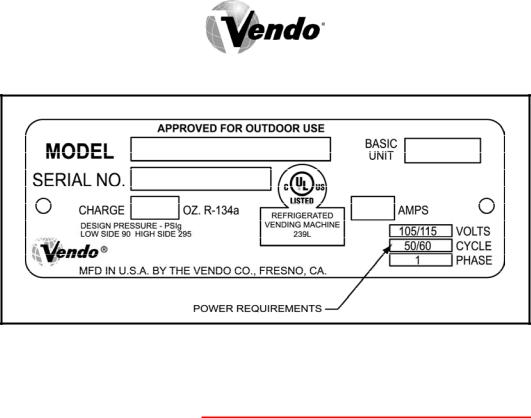
FIGURE 4
NOTE: The Model number of the vending machine is located on the top, left hand corner of the serial plate. Do Not use the “BASIC UNIT” number. The
BASIC UNIT number is the cabinet size, which is used on a number of different machines. A typical model number could read “540TDD00029”. The 540 is the model number, TDD represents the product line of the vendor, and the remaining digits tell what options are included.
G-4 |
09/2003 |
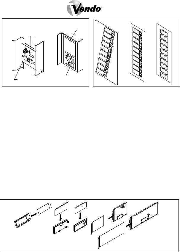
COIN INSERT |
COIN INSERT |
STYLE A |
STYLE B |
STYLE C |
A |
B |
|
|
|
|
COIN INSTRUCTION LABEL |
|
|
|
|
PRICE DISPLAY |
|
|
|
PRICE DISPLAY
COIN INSTRUCTION LABEL
FIGURE 5 |
FIGURE 6 |
|
LABEL INSTALLATION |
COIN INSTRUCTION LABEL & PRICE LABEL APPLICATION:
Apply labels to a clean and dry surface. Peel backing from label and apply with firm, even pressure.
INSTRUCTION LABEL
(Refer to Figure 5 for the following information.)
Coin insert “A” has a separate validator opening, and insert “B” shows the validator opening built into the coin insert. Apply instruction label to area shown (as needed by the vendor).
FLAVOR LABELS INSTALLATION:
In Figures 6 & 7, corresponding styles are indicated by A, B, C, D, or E notations.
Insert flavor labels to the side or top of selection window or button depending on the style. See Figure 6 for selection style. Rear views of windows and buttons are shown in Figure 7. Arrows point the direction to insert labels.
Selection window and selection button labels identify product contained in columns.
STYLE- A |
STYLE- D |
STYLE- E
STYLE- B STYLE- C
NOTE: The selection panel used with styles D and E is not depicted in Figure 6.
FIGURE 7
G-5 |
09/2003 |
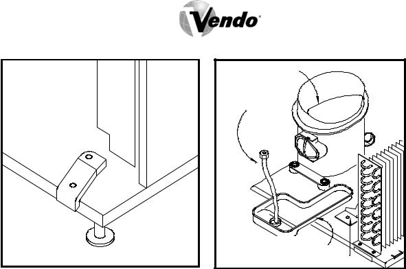
FIGURE 8 FIGURE 9
COMPRESSOR |
DRAIN TUBE |
CONDENSATION PAN |
CONDENSER FAN BRACKET |
ALIGNMENT CHECKS
DOOR ROLLER CHECK:
The door support is to insure that the outer door closes squarely to the cabinet.
Raising the door can also insure proper alignment of the door latch (see Figure 8).
REFRIGERATION AREA CHECK:
Check the position of the condensation pan (see Figure 9). The correct position of the pan is between the compressor and the condenser fan bracket. Be sure the drain tube is clipped to the pan and is free of kinks. A water trap is installed into the condensation pan and will prevent warm, moist air from reaching the evaporator area.
G-6 |
09/2003 |
LOADING INSTRUCTIONS
BASIC LOAD SET-UP:
The V-Max machine is capable of vending a variety of products. For specific information, refer to the product set-up label on the machine inner door or contact the Technical Services Department of the Vendo office in your area.
Load product evenly. Bottles are loaded with crown end placed toward the back of the column. In initial loading, prime the machine by advancing the product into the buckets. To advance product into buckets, use the vend test function of the electronic controller. When the bucket is loaded, the column is ready to vend.
PRIME ALL COLUMNS DURING INITIAL PRODUCT LOADING
G-7 |
09/2003 |

VEND MECHANISM PARTS DESCRIPTION
The parts listed below are part of the vend motor mechanism (refer to Figure 10 on page G-9). One mechanism is required per column. The parts are interchangeable. Setting will differ between single, double, triple, and quadruple depth.
VEND MOTOR ASSEMBLY: P/N 1115821
The motor is attached to the mech plate by three screws.
TIMING CAM: P/N 1113236; RETAINER: P/N 1113244
The motor cam assembly consists of two parts, the cam and the cam retainer. The cam controls the vend cycle. The cam is attached to the motor by the cam retainer. The retainer rotates left or right, and provides for single, double, triple, or quadruple depth operation.
SOLD-OUT SWITCH: P/N 368299
There is one sold-out switch above the vend motor. The sold-out switch is actuated by the sold-out flap when the column is empty. It prevents the motor from running when the columns are empty.
VEND BUCKET: P/N 1120146
The vend bucket holds the product(s) in a “ready to vend” position at the base of each column.
MOTOR COUPLING: P/N 1076465
The adapter coupling couples the motor to the bucket. It is located behind the motor, on the motor shaft.
ANTI-THEFT CLIP: P/N 389712
The anti-tilt clip prevents product from dropping out of the bucket if the vendor is tilted. The anti-theft clips are located in the bucket.
GATE: P/N 1121282
The gate holds product above the vend bucket.
G-8 |
09/2003 |
 Loading...