

Page 1
DV
M
A
A
M
ÍM
E
A
K
U
E
T
ÉR
T
I
G
T
I
I
3
2
3
83450
6
E
A
DIGIT
DIGIT
MULTI
MULT
3½-ST
USER M
GEBRUI
MODE D'
MANUAL
BEDIEN
893
L MULTIMET
LE MULTIME
TRE NUM
ETRO DIGIT
LLIGES MUL
NUAL
ERSHANDLEID
EMPLOI
DEL USUARIO
NGSANLEITUN
R 3½ DIGI
ER 3½-DIG
IQUE 3½-D
AL DE 3½ –
IMETER – 3
NG 1
S – 32 RANG
TS – 32 BER
GITS – 32 G
2 RANGO
BEREICHE
6
ES
IKEN
MMES
Page 2
DVM893
V. 03 – 01/02/2013 2 ©Velleman nv
Page 3
1
t
n
T
dtaye
b
h
h
e
U
r
l
T
e
d
e
t
r
a
p
y
r
e
e
e
v
e
e
i
n
i
i
u
i
r
u
n
3
o
e
m
.
n
o
d
t
a
a
t
n
o
o
h
t
c
o
.
o
t
h
d
u
o
o
t
n
f
a
DVM89
1. In
To all res
Importa
If in dou
Thank you
bringing t
or use it a
Refer to t
manual.
2. Us
roduction
idents of the Eu
t environmenta
his symbol on th
evice after its lif
he unit (or batte
specialized com
our distributor o
nvironmental rul
t, contact your
for choosing Vell
is device into ser
nd contact your d
e Velleman® S
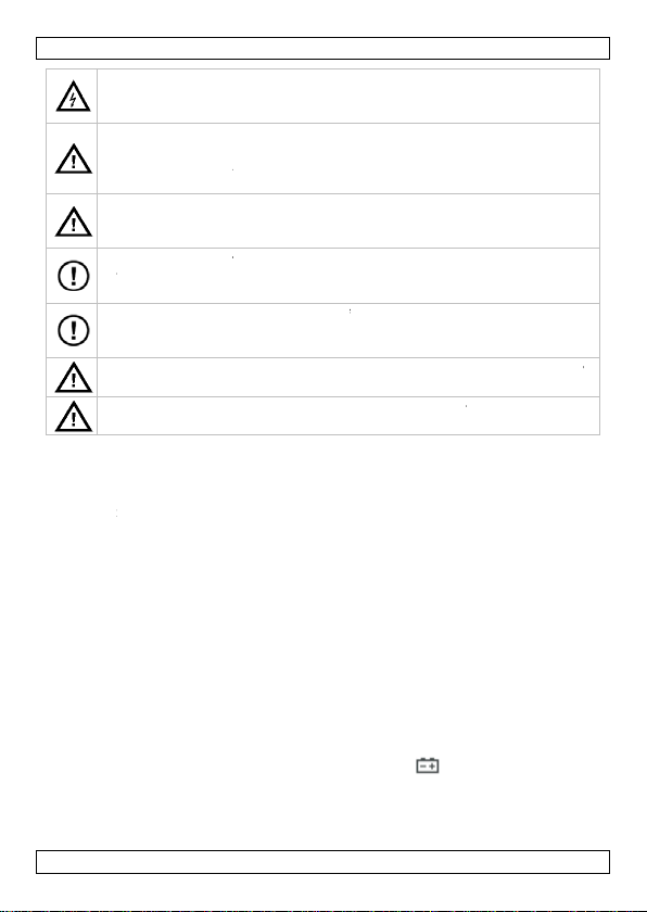
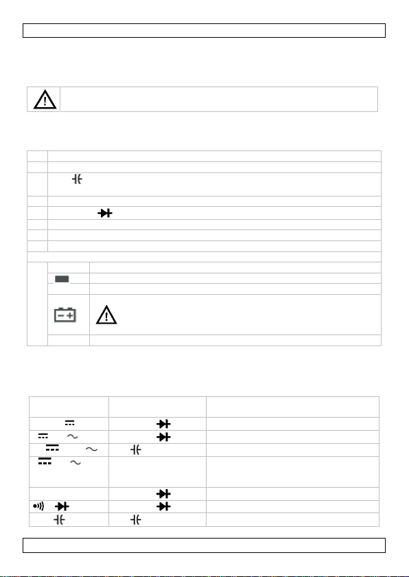
d Symbols
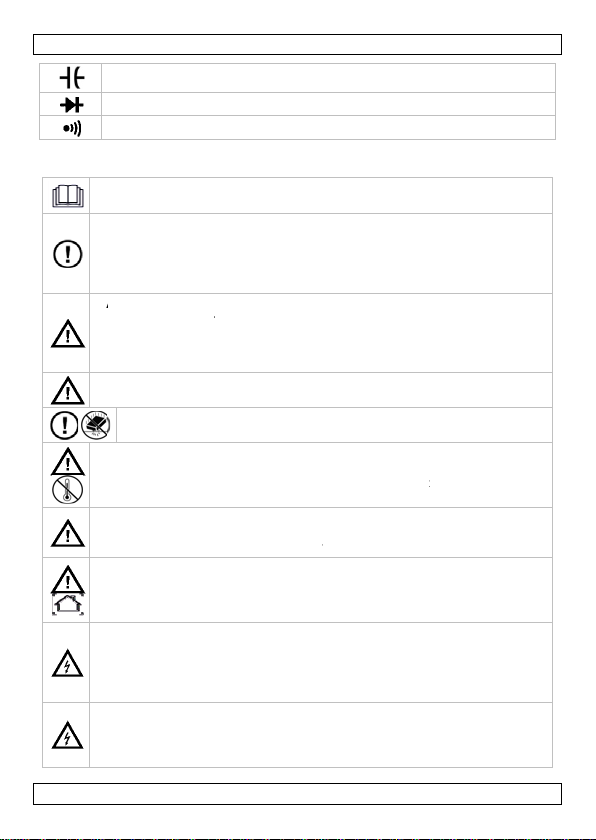
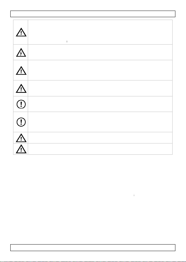
This symbol ind
Not reading the i
death.
This symbol ind
A hazardous cond
This symbol ind
Risk of a hazardo
injury or death.
This symbol ind
Ignoring this info
AC (Alternating C
DC (Direct Curre
Both AC and DC
Double insulation
Earth
Fuse
Capacitor
Diode
SER MA
opean Union
information ab
device or the pa
cycle could harm
ies) as unsorted
any for recycling
to a local recycli
s.
local waste disp
man! Please rea
ice. If the device
aler.
rvice and Qualit
cates: Read ins
structions and m
cates: Danger.
ition or action tha
cates: Risk of d
s condition or ac
cates: Attentio
mation can lead t
rrent)
t)
(class II-protecti
NUAL
ut this product
ckage indicates t
the environment.
unicipal waste; i
This device shou
g service. Respe
sal authorities
the manual thor
was damaged in
y Warranty on t
ructions.
nual can lead to
t may result in inj
nger/damage.
ion that may res
; important inf
hazardous situa
n)
at disposal of the
Do not dispose o
should be taken
ld be returned to
t the local
ughly before
ransit, don't inst
e last pages of th
amage, injury or
ury or death.
lt in damage,
rmation.
ions.
to
is
ll
V. 03 – 0
/02/2013
3
©Velleman
v
Page 4
1
f
e
n
Apri
aRe
e
vmoreaerr
hmetha
i
e
slea
wwhNe
sme
e
t
p
A
o
h
a
i
d
e
t
m
s
g
h
o
y
n
e
e
o
s
3
r
u
n
t
r
e
a
n
n
r
v
t
a
u
d
o
n
a
p
e
h
d
n
t
e
t
w
e
c
u
r
r
h
d
T
n
h
o
c
a
s
o
e
s
d
s
n
m
e
o
s
,
o
3. Sa
Continuity
ety Instruc
R
ad this manual th
de
vice before actual
O
ly use the device
un
authorized way w
ce
rtain guidelines in
de
aler will not acce
W
RNING: To avoi
or to opening the
ba
tteries and fuses
m
nual.
mark: Refer to t
K
ep the device aw
Protect this dev
operating.
A
oid cold, heat an
ved from a cold t
ched room temp
ors.
T
is is an installa
asuring instru
n indicated. Refe
Po
llution degree 2-d
ra
n, moisture, spla
to
§5 Pollution de
Fo
r your safety, use
fore use, check t
B
te
t leads if they lo
ds of the same t
Al
ays place your fi
ile measuring!
ver touch free te
U
e the correct inpu
asurements. Wh
ch
eck that the rang
To
avoid damages t
th
input values as
DVM89
ions
oroughly. Familia
ly using it.
for its intended p
ill void the warra
this manual is no
t responsibility fo
d electrical shock
housing. To prev
f the same type
e warning on the
y from children a
ce from shocks a
large temperatu
o a warm location
rature. This to a
ion category CA
ent. Never use
r to §4 Overvolt
evice. For indoor
hing and dripping
ree.
only the test lea
at they are in go
k damaged. Whe
pe and with the s
gers behind the
rminals when the
t terminals, functi
n the range of th
initially set on t
the instrument,
hown in the tech
ise yourself with
rpose. Using the
ty. Damage caus
covered by the
any ensuing def
always disconne
nt damage or inj
nd ratings as spe
back of the mete
d unauthorised u
d abuse. Avoid b
e fluctuations. W
, leave it switche
oid condensation
T III 600V / CA
his equipment in
ge/installation
se only. Keep thi
liquids. Not for i
s supplied with t
d condition. Do n
damaged, repla
me specification
rotective edges
meter is connect
on, and range for
value to be mea
e meter is the hig
o not exceed the
ical specification
he functions of th
device in an
d by disregard of
arranty and the
cts or problems.
t the test leads
ry, only use
cified in this
.
sers.
ute force when
en the unit is
off until it has
and measuring
II 1000V
a higher category
category.
s device away fro
dustrial use. Ref
e instrument.
t use the meter
e them with test
.
f the test probes
d to a circuit.
your
ured is unknown
hest possible.
maximum limits
tables.
e
r
r
f
V. 03 – 0
/02/2013
4
©Velleman
v
Page 5
1
smehig
h
h
stes
r
oaccacc
w
m
e
t
f
d
m
t
e
c
D
T
e
e
,
r
s
o
A
o
n
r
t
t
r
c
c
s
r
t
e
a
e
r
i
r
b
d
e
s
v
e
r
o
p
r
3
a
c
m
a
u
d
f
r
b
e
e
n
a
i
h
m
o
n
o
i
r
b
r
s
n
o
a
e
n
r
e
r
h
o
o
)
h
n
A
a
p
n
g
y
y
t
s
y
t
Ri
W
vo
W
vo
Di
us
In
ci
ca
D
S
or
All
ca
• If the
may be
• Use th
provide
• Use ex
• Do not
• Verify t
meter i
have th
be use
• When
connec
lead (r
• Before
the circ
• For all
reading
hen s
• Use a 9
meter.
• Replac
battery
and pe
• Do not
• Always
V. 03 – 0
k of electric sh
asuring live circu
her than 60 VDC
en using the mA
ltages > 250 V.
en using the 10
ltages > 500 V.
connect circuit p
ting resistance, c
e the included tra
TV repair work o
cuits, remember
n damage the me
not replace inte
essories by ident
essories, e.g. te
itch off the mete
fuses.
modifications of
used by user mod
eter is used near
come unstable or
meter only as sp
d by the meter m
reme caution wh
operate the mete
he meter’s operat
it operates abno
e meter serviced
until it is repaire
aking connection
ing the live test l
d) before disconn
hanging function
uit under test.
C functions, to a
s, verify the pres
lect a DC voltage
V battery, prope
the battery as s
the meter may
sonal injury.
operate the mete
verify that all con
/02/2013
DVM89
ck during oper
its. Use extreme
or 30 VAC rms.
terminal: do not
terminal: do not
wer and discharg
ontinuity, capacit
sistor socket.
when carrying o
hat high-amplitu
er. Use of a TV fil
nal parts yoursel
ical ones with the
t leads, from you
and remove test
he device are for
ifications to the d
a source of electr
may indicate larg
cified in this ma
y be impaired.
n working around
near explosive g
on by measuring
mally. Protection
y a qualified tec
.
s, connect the co
ad (red). When d
ecting the comm
or measuring ra
oid the risk of sh
nce of any AC vol
range equal to or
ly installed in the
on as the battery
roduce false read
with the case (o
nections are relia
5
tion. Be very ca
aution when mea
easure current i
measure current i
e all high-voltage
nce or diodes. Fo
t measurements
e voltage pulses
ter will attenuate
. Replace damag
same specificatio
dealer.
probes prior to re
idden for safety
vice is not cover
omagnetic interfe
errors.
ual; otherwise, t
bare conductors
ses, vapour, or d
a known voltage.
may be impaired.
nician. Make sure
mon test lead (b
isconnecting, disc
n test lead (black
ge, disconnect t
ck due to possibl
tages first by usi
greater than the
meter’s battery c
indicator ap
ngs that can lead
part of the case)
le and safe.
eful when
uring voltages
circuits with
n circuits with
capacitors before
r transistor tests,
n power switchin
t the test points
any such pulses.
d or lost
s. Order spare
placing the batter
easons. Damage
d by the warrant
ence, the display
e protection
r bus bars.
ust.
Do not use the
When in doubt,
the device canno
lack) before
nnect the live te
.
e test leads from
e improper
g the AC function
C range.
se, to power the
ears. With a low
to electric shock
removed.
©Velleman
.
t
.
v
Page 6

DVM893
• Avoid body contact with ground potential (e.g. metallic terminals, output
sockets, lead clamp…) while measuring. Make sure to be electrically insulated
from ground during measurement.
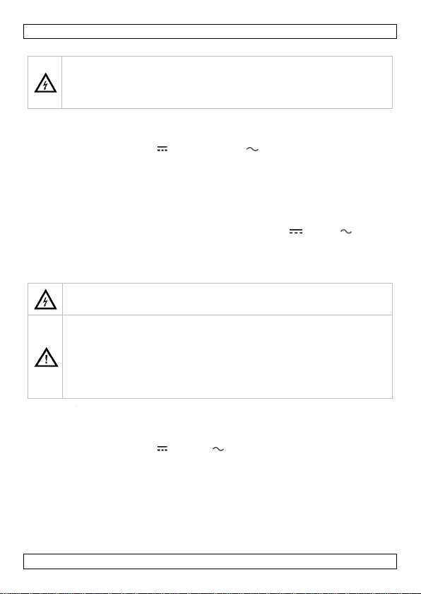
4. Overvoltage/Installation Category
DMMs are categorized depending on the risk and severity of transient overvoltage
that might occur at the point of test. Transients are short-lived bursts of energy
induced in a system, e.g. caused by lightning strike on a power line.
The existing categories according EN 61010-1 are:
CAT I A CAT I-rated meter is suitable for measurements on protected
electronic circuits that are not directly connected to mains power, e.g.
electronics circuits, control signals…
CAT II A CAT II-rated meter is suitable for measurements in CAT I
environments and mono-phase appliances that are connected to the
mains by means of a plug and circuits in a normal domestic
environment, provided that the circuit is at least 10 m apart from a
CAT III, or 20 m apart from a CAT IV environment. E.g. household
appliances, portable tools…
CAT III A CAT III-rated meter is suitable for measurements in CAT I and CAT II
environments, as well as for measurements on (fixed) mono- or polyphased appliances which are at least 10 m apart from a CAT IV
environment, and for measurements in or on distribution level
equipment (fuse boxes, lighting circuits, electric ovens).
CAT IV A CAT IV-rated meter is suitable for measuring in CAT I, CAT II and
CAT III environments as well as on the primary supply level.
Note that for all measurements on equipment for which the supply
cables run outdoors (either overhead or underground) a CAT IV meter
must be used.
Warning: This device was designed in accordance with EN 61010-1 installation
category CAT III 600V / CAT II 1000V. This implies that certain restrictions in use
apply that are related to voltages and voltage peaks which can occur within the
environment of use. Refer to the table above.
This device is suitable for measurements up to 1000 V:
• Protected electronic circuits that are not directly connected to mains power, e.g.
electronics circuits, control signals, circuits behind isolating transformer…
• circuits that are directly connected to mains power, but limited to:
o measurements on mono-phase appliances that are connected to the mains
by means of a plug
o mono-phase appliances and circuits directly connected to the mains in a
normal domestic environment, provided that the circuit is at least 10 m apart
from a CAT III, or 20 m apart from a CAT IV environment. E.g. household
appliances, portable tools, light circuits at more than 10 m from a
distribution board…
This device is suitable for measurements up to 600 V:
• measurements in/on low-voltage distribution boards (distribution boards behind
meter box)
V. 03 – 01/02/2013 6 ©Velleman nv
Page 7
DVM893
• measurements on (fixed) mono- or poly-phased appliances and circuits except
in CAT IV environments (e.g. mains outlets, electric ovens, lighting circuits, bus
bars, low-voltage distribution boards and circuit breakers).
This device is NOT suitable for:
• Voltages above 1000 V
• Measurements on distribution equipment and outdoor installations including
meter boxes and equipment/circuits outside or remote from the domestic
environment e.g. circuits in sheds, garden houses and free-standing garages, or
circuits using underground wiring e.g. garden lighting, pool-pump…
This device is only suitable for measurements up to 600 V in CAT III and
up to 1000 V in CAT II.
5. Pollution Degree
IEC 61010-1 specifies different types of pollution environments, for which different
protective measures are necessary to ensure safety. Harsher environments require
more protection, and the protection against the pollution which is to be found in a
certain environment depends mainly on the insulation and the enclosure
properties. The pollution degree rating of the DMM indicates in which environment
the device may be used.
Pollution
degree 1
Pollution
degree 2
Pollution
degree 3
Pollution
degree 4
Warning: This device was designed in accordance with EN 61010-1 pollution
degree 2. This implies that certain restrictions in use apply that are related to
pollution which can occur within the environment of use. Refer to the table above.
No pollution or only dry, nonconductive pollution occurs. The pollution
has no influence (only to be found in hermetically sealed enclosures).
Only nonconductive pollution occurs. Occasionally, temporary
conductivity caused by condensation is to be expected (home and
office environments fall under this category).
Conductive pollution occurs, or dry nonconductive pollution occurs that
becomes conductive due to condensation that is to be expected
(industrial environments and environments exposed to outside air but not in contact with precipitation).
The pollution generates persistent conductivity caused by conductive
dust or by rain or snow (exposed outdoor environments and
environments where high humidity levels or high concentrations of fine
particles occur).
This device is only suitable for measurements in Pollution degree
class 2 environments.
6. Overview
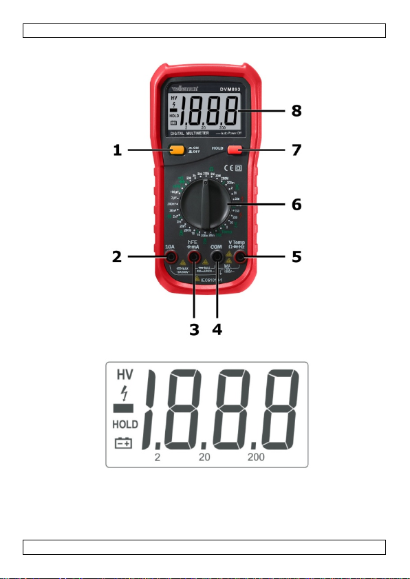
Refer to the illustrations on page 2 of this manual.
1 power ON/OFF button
2 10A: input terminal for currents > 200 mA
3
hFE mA: input terminal for transistor, capacitance, and current
measurements < 200 mA
V. 03 – 01/02/2013 7 ©Velleman nv
Page 8
1
m
r
D
d
D
e
u
e
m
w
O
e
a
h
e
e
e
u
t
e
t
h
g
s
i
r
b
e
A
A
o
o
h
e
e
3
o
m
V
e
e
o
p
0
0
A
0
0
A
0
4
w
o
n
c
e
/
o
o
4
e
o
r
n
t
/
y
4 COM:
5
V Te
6 Rota
7 HOL
8 LCD
Display:
HV
HOL
1
7. Us
7.1 Inp
Never exc
Function
200 mV
V & V
mA &
A & A
Ω
/
hFE,
temperatu
Hz
7.2 Po
Press the
off.
The devic
feature ex
the device
7.3 Dat
The data
[7] to ent
again to r
common input t
p Hz: inp
y switch: to selec
: to lock the curr
isplay, 3 full digi
Indicates hig
Indicates ne
The meter is
The battery i
Warn
elect
soon as the
Over range.
t Protection
ed the limit valu
Red lead
V Temp
V Temp
A
hFE m
10A
V Temp
V Temp
hFE m
re
V Temp
V Temp
er ON/OFF Butt
N/OFF button to
switches off aut
tends the life of y
on again.
Hold Mode
old mode locks t
r data hold mod
turn to normal m
DVM89
rminal
t terminal for all
type of measure
nt reading
s and 1 half (max
voltage (1000
ative reading.
in data hold mod
low.
ng: To avoid fals
ic shocks or pers
attery indicator a
for protection.
connection In
Hz
Hz
Hz
Hz
Hz
Hz
on
switch the meter
matically after ±
ur battery. Press
e current readout
. The display sho
easuring mode.
ther measureme
ent and range
. range 1999)
DC or 750 VAC).
.
readings, which
nal injury, replac
ppears.
ut protection
25
VDC or 250 VAC
10
0 VDC or 750 VA
fus
e protection F250
fus
e protection F10A
10
A DC or AC rms f
25
VDC or 250 VAC
25
VDC or 250 VAC
fus
e protection F250
e protection F250
fus
25
VDC or 250 VAC
on. Push the butt
0 minutes. This
the ON/OFF butt
on the display. P
s “HOLD”. Press
ts
an possibly lead
the battery as
rms
C rms
mA/250V
500V (ceramic),
r max. 10 s
rms
rms
mA/250V
mA/250V
rms
n again to switch
nergy-saving
n twice to switch
ess the HOLD ke
the HOLD key
o
it
V. 03 – 0
/02/2013
8
©Velleman
v
Page 9
1
a
o
omo
e
e
r
t
y
e
o
e
m
t
o
a
a
o
r
oattpoToUsNe
e
r
r
r
f
a
t
e
o
a
k
e
e
o
h
s
h
C
e
e
g
V
l
s
s
u
u
h
s
t
m
t
e
m
a
v
A
l
r
c
o
p
3
a
V
a
V
s
t
e
a
o
r
V
d
l
t
.
(
2
e
s
s
e
e
m
e
M
V
g
e
s
u
a
t
e
b
e
b
m
c
t
0
h
e
x
t
A
e
t
c
n
p
s
e
h
t
t
7.4 Me
DC voltag
AC voltag
To measu
1. Selec
rotar
2. Conn
“V” s
3. Conn
The
nega
prece
Notes: Th
even with
tips of the
measure
7.5 Me
The mete
To measu
1. Cut o
2. Disch
3. Selec
4. Conn
“mA”
move
unkn
the r
ideal
5. Brea
6. Conn
the r
V. 03 – 0
suring AC/DC V
T
avoid electrical s
to
measure voltage
T
avoid electrical s
re than 1000 VD
ea
rth ground.
measuring rang
measuring rang
e AC or DC volta
the appropriate
switch.
ct the black test
cket.
ct the test probe
easured value ap
ive polarity is pre
ded by a “–” sign.
e displayed value
ut input or witho
test probes toget
gain.
suring AC/DC C
T
avoid electrical s
ci
cuit power and di
cu
rrent.
T
avoid damage to
empt an in-circui
tential to earth is
avoid damage to
e the proper ter
ver place the tes
th
leads are plugg
fo
longer than 15
’s ranges are: 2.0
e current:
f the power suppl
rge all the high-
the appropriate
ct the black test
socket for measu
the red test lead
wn beforehand,
nge switch in the
resolution is obtai
the circuit path t
ct the black test
d test probe to th
/02/2013
DVM89
ltage
ock and/or dam
exceeding 1000
ock and/or dam
or 750 VAC rms
: 200.0 mV, 2.00
: 2.000 V, 20.00
es:
(DC voltage)
ead to the “COM”
in parallel to th
pears on the displ
ent at the red te
may be unstable
t connecting the
her and make sur
rrent
ock and/or dam
charge all high-v
the meter or inju
current measure
higher than 250
the meter, check
inals, function an
probes in paralle
d into the curren
inutes.
00 mA, 20.00 mA
y of the circuit to
oltage capacitors
(DC) or A
ead to the “COM”
ements of max.
to the “10A” sock
onnect the red te
highest range po
ned.
be tested.
robe to the mor
e more positive si
9
ge to the instrum
DC or 750 VAC r
ge to the instrum
between the CO
0 V, 20.00 V, 200
, 200.0 V, 750 V
or V (AC volta
socket and the r
e circuit under te
ay. For DC meas
t probe, the indic
in the 200 mV
est probes. In thi
the meter displa
ge to the instrum
ltage capacitors
y in case of a fus
ment where the o
.
the meter’s fuse
range for your
with a circuit or
terminals. Do no
, 200.0 mA, 10.0
measure.
AC) range with t
socket and the r
00 mA. For a ma
t. If the current
t lead to the “10
ition. Then reduc
negative side of
de of the break (
nt, do not attem
s.
nt, do not apply
terminal and the
.0 V, 1000 V.
.
e) range with the
d test lead to the
t.
rements: if a
ted value is
and 2 V range
s case, hold the
ys zero; then
nt, disconnect th
efore measuring
blow, never
pen-circuit
efore proceeding
easurement.
omponent when
measure current
A.
e rotary switch.
d test lead to the
imum of 10 A,
o be measured is
” socket and set
gradually until t
he break; connec
onnection
©Velleman
t
,
e
.
e
v
Page 10
1
r
h
m
t
e
f
a
o
a
ocirresNe
r
,
r
t
e
o
e
m
a
e
e
c
a
r
m
t
ocirdioNe
d
h
e s
h
s
a
v
s
s
c
h
s
s
0
“
l
s
u
e
e
e
t
t
c
h
s
o
u
o
l
3
e
s
t
.
n
a
o
e
0
e
m
i
s
u
t
u
e
a
o
n
.
n
u
a
e
b
e
e
s
m
e
g
f
e
c
e
b
u
e
n
d
e
c
in se
dama
7. Switc
The
nega
prece
rang
8. Cut o
9. Disch
10. Rem
11. Resto
7.6 Me
The mete
20.00 M
To measu
1. Selec
2. Conn
“Ω” s
3. Conn
The
Notes:
• The me
rated v
paths b
• To incr
of the t
Subtra
• For resi
needs
measu
• If the
circuit,
7.7 Tes
To test a
1. Set t
2. Conn
ies). Reversing t
ge the meter.
on the power su
easured value ap
ive polarity is pre
ded by a “–” sign.
limit, the display
f the power suppl
rge all the highve the test probe
re the circuit to it
suring Resistan
T
avoid electrical s
cuit power and di
istance.
ver perform re
’s ranges are: 20
200.0 M.
e resistance:
the appropriate
ct the black test
cket.
ct the test probe
easured value ap
asured value of a
lue. This is beca
etween the probe
ase accuracy wh
st probes togeth
t this value from
stance measurem
few seconds to s
ing.
easured resistan
the display shows
ing Diodes
T
avoid electrical s
cuit power and di
des.
ver perform di
iode out of a circ
e rotary switch t
ct the black test
ocket.
DVM89
e probes will giv
pply of the circuit
pears on the displ
ent at the red te
When the measu
shows “1”. Selec
y of the circuit to
oltage capacitors
from the circuit.
original conditio
e
ock and/or dam
charge all high-v
istance measur
.0, 2.000 k, 2
Ω” range with th
ead to the “COM”
to the circuit/co
pears on the displ
resistor in a circu
se the meter’s te
tips.
n measuring low
r to determine th
he measured val
ents in the 20 M
abilize the reado
e exceeds the sel
“1”.
ock and/or dam
charge all high-v
de measureme
it:
the position
ead to the “COM”
a negative readi
to measure.
ay. For DC meas
t probe, the indic
red value is highe
a higher range.
measure.
.
ge to the instrum
ltage capacitors
ments on a liv
.00 k, 200.0 k
rotary switch.
socket and the r
ponent under te
ay.
t often differs fro
t current flows th
resistance values,
e resistance valu
e of the circuit.
and 200 M ran
t. This is normal
cted range or in
ge to the instrum
ltage capacitors
ts on a live circ
socket and the r
g, but will not
rements, when a
ted value is
r than the selecte
nt, disconnect th
efore measuring
circuit.
, 2.000 M,
d test lead to the
t.
the resistor’s
rough all possible
first hold the tips
of the test leads.
es, the meter
or high resistanc
ase of an open
nt, disconnect th
efore testing
it.
d test lead to the
e
e
V. 03 – 0
/02/2013
10
©Velleman
v
Page 11
1
e
e
m
e
i
e
c
H
r
ocir
e
r
h
e
o
e
n
e
a
ocir
sDo
r
r
t
e so
e
m
m
t
e
e
t
p
s
e
h
e
T
h
s
n
o
l
s
e
a
n
h
s
e
a
l
s
p
e
p
h
3
o
e
y
m
u
a
a
o
m
y
a
a
o
t
u
2
t
c
e
d
a
g
e
b
e
s
r
h
e
b
a
e
F
e
t
o
c
s
p
o
n
e
h
f
3. Conn
prob
The
conn
Notes:
• Measur
Consid
• In a cir
0.8 V.
of othe
7.8 Aud
To test fo
1. Set t
2. Conn
“” s
3. Conn
If the
conti
exce
“1”.
7.9 Me
The mete
To measu
1. Selec
2. Conn
3. Conn
The
Notes:
• When
readou
• To incr
hold th
the tes
ct the black test
to the anode (po
eter displays the
ction is reversed,
ng diodes that ar
r disconnecting t
uit, a good diode
owever, the reve
pathways betwe
ible Continuity
T
avoid electrical s
cuit power and di
co
ntinuity.
N
ver perform co
continuity:
e rotary switch t
ct the black test
cket.
ct the test probe
measured resista
uously and the r
ds the selected r
suring Capacita
T
avoid electrical s
cuit power and di
ca
pacitance. Use th
di
charged.
not perform c
’s ranges are: 2.0
e capacitance:
the appropriate
ct the black test
cket.
ct the test probe
easured value ap
easuring bulk ca
.
ase accuracy wh
tips of the test
leads. Subtract t
DVM89
robe to the cath
itive) of the diod
approximate forw
the meter displa
part of a circuit
em from the circ
should produce a
rse bias reading c
n the probe tips.
est
ock and/or dam
charge all high-v
tinuity tests on
the position.
ead to the “COM”
to the circuit/co
nce is less than ±
sistance is displa
nge or in case of
ce
ock and/or dam
charge all high-v
DC voltage func
pacitance meas
00 nF, 20.00 nF,
range with the
ead to the “COM”
to the capacitor
pears on the displ
acitors, the mete
n measuring low
robes together to
is value from th
de (negative); co
.
ard voltage drop.
s “1”.
ight produce fau
it.
forward bias rea
n vary dependin
ge to the instrum
ltage capacitors
a live circuit.
socket and the r
ponent under te
50 , the buzzer
ed. If the measu
n open circuit, t
ge to the instrum
ltage capacitors
ion to confirm th
rements on liv
00.0 nF, 2.000 µ
rotary switch.
socket and the r
o measure.
ay.
r needs a few sec
apacitance value
determine the ca
measured value
nnect the red test
If the probe
lty results.
ing of 0.5 V to
on the resistanc
nt, disconnect th
efore testing the
d test lead to the
t.
sounds
ed resistance
e display shows
nt, disconnect th
efore measuring
t the capacitors a
circuits.
, 100.0 µF.
d test lead to the
nds to stabilize t
(< 2 nF), first
acitance value o
f the circuit.
e
e
re
e
V. 03 – 0
/02/2013
11
©Velleman
v
Page 12
1
n
omoUs
r
h
n
m
e
a
othameUs
M
g
r
h
e
n
r
t
a
:
h
a
oin
r
h
e
s
e
m
E
h
a
o
d
a
e
m
h
o
a
t
l
V
r
a
u
o
d
a
e
K
p
a
t
c
l
o
l
s
3
a
b
t
o
e
u
e
r
v
t
e
e
w
t
e
t
o
e
u
y
a
e
d
r
d
e
t
e
p
n
h
a
T
e
e
e
n
a
h
s
7.10 Tra
To measu
1. Set t
2. Disco
socke
socke
“
3. Deter
emitt
the in
The d
7.11 Me
Caution:
measurin
To measu
1. Set t
temp
2. Disco
socke
socke
mete
3. Inser
indic
Note
4. Touc
The d
7.12 Me
To measu
1. Set t
2. Conn
“Hz”
3. Conn
The
sistor Test (hF
T
avoid electrical s
re than 250 VDC
terminal.
e the included ad
e a transistor:
e rotary switch t
nect the test lea
t with correct pol
t of the meter; th
A” socket of the
mine whether the
r, the base and t
cluded adaptor s
isplay shows the
suring Tempera
T
prevent electrica
n 60 VDC or 24
asure temperatu
e the included ad
ax. temperature
higher temperat
e temperature:
e rotary switch t
rature.
nect the test lea
t with correct pol
t of the meter; th
.
the plug of the
ted polarity (“+”
Push the temper
the object to me
isplay shows the
suring Frequen
T
prevent electrica
circuits with volta
e frequency:
e rotary switch t
ct the black test
ocket.
ct the test probe
easured value ap
DVM89
)
ock and/or dam
or 250 VAC rms
ptor socket.
the “hFE” positio
s from the socke
rity: the “COM” (
“IN” (or “+”) pl
eter.
transistor is of th
e collector. Inse
cket.
pproximate hFE-
ure
shock, do not m
AC rms. To prev
es inside a micro
ptor socket and
is 250 °C with th
res (up to 1000 °
the “Temp” posit
s from the socke
rity: the “COM” (
“IN” (or “+”) pl
-thermocouple in
lug goes into the
ature probe firml
sure with the th
emperature.
y
shock or meter
ges > 250 VDC o
the “Hz” position
ead to the “COM”
to the circuit un
pears on the displ
ge to the instrum
etween the COM
n.
s and plug in the
r “–”) plug goes i
g goes into the
NPN- or PNP-ty
t the leads into th
alue (current gai
asure objects wit
nt fire or meter d
ave oven.
hermocouple.
included thermo
C), use a suitable
ion. The meter sh
s and plug in the
r “–”) plug goes i
g goes into the “
the adaptor sock
“+” socket).
into the socket.
rmocouple probe.
amage, do not m
AC rms.
.
socket and the r
er test.
ay.
nt, do not apply
erminal and the
multi-functional
nto the “COM”
e and locate the
e proper holes in
).
voltages higher
mage, never
couple. For
thermocouple.
ows the ambient
multi-functional
nto the “COM”
emp” socket of t
t according to the
asure frequencie
d test lead to the
e
V. 03 – 0
/02/2013
12
©Velleman
v
Page 13
1
e
o
m
s
o
a
p
m
o
v
m
WAbefexa
tRem
t
i
e
M
d
e
h
o
t
y
R
e
sToalw
onoba
M
n
n
m
r
d
o
t
e
e
n
h
t
r
i
o
m
s
t
a
a
e
e
f
e
t
a
n
3
d
t
o
a
t
o
e
e
b
c
e
o
r
d
u
n
n
e
a
f
f
e
e
u
d
s
d
o
n
c
t
d
c
a
a
a
e
v
d
s
k
t
n
d
s
d
e
o
t
f
t
8. Cl
Instructi
• Meter c
perfor
hazard
to do s
inform
• When
replace
• Before
you ha
• Be awa
in the
ins
Do
by
tes
Sw
fus
General
Wipe the
detergent.
Dirty or w
1. Switc
2. Rem
from
3. Gentl
4. Soak
5. Make
again
Battery
V. 03 – 0
aning and
ns for Safe Mai
alibration, mainte
ed by technicians
. Do not attempt
and have the rel
tion.
erforming meter
ent parts.
pening the mete
e no static electri
re that there may
eter even after p
RNING: To avoi
ore opening the h
ct same specifica
rument, do not g
ark: refer to th
not replace inter
identical ones wit
leads, from you
tch off the meter
s.
aintenance
evice regularly w
Do not use alcoh
t input sockets
off the meter.
ve the test probe
he input sockets.
remove any dirt
a new cotton bud
sure the sockets
.
eplacement
w/bad batteries c
Lo
el
ctric shocks or p
as
soon as the batt
U
e only batteries o
avoid shock or p
ays turn off the
D
not puncture ba
t attempt to rech
tteries in accorda
ch
ildren.
/02/2013
DVM89
aintenance
tenance
ance, repair, an
who fully unders
to repair or servic
evant calibration,
aintenance, only
, disconnect all p
city to avoid dam
be dangerous vol
owering off.
electrical shock,
using. To preven
ions. To avoid el
t water inside th
warning on the
al parts yourself.
the same specifi
dealer.
and remove test l
th a moist, lint-fr
l, solvents or ab
ay affect the rea
from the circuit
that may be in th
with a cleaning a
re perfectly clea
n produce false r
rsonal injury. Th
ry indicator
the specified typ
rsonal injury, be
meter and discon
teries or throw th
rge non-recharg
ce with local reg
13
other operations
and the meter an
e the meter unles
performance test
use specified an
wer supplies and
ging the meter c
ages remaining i
always disconne
t fire hazards, ins
ctrical shock and/
housing.
ack of the meter.
Replace damage
ations. Order sp
eads prior to repl
e cloth and a sm
asive products.
ings. To clean th
nder test. Remo
e sockets.
d oiling agent an
and dry before u
eadings, which ca
refore, you must
ppears.
e and rating (9 V)
ore opening the b
nect the test lead
m in fire as they
able batteries (al
lations. Keep bat
can only be
electrical shock
you are qualifie
and service
approved
make sure that
mponents.
some capacitors
t the test leads
all fuses with the
or damage to the
or lost accessori
re accessories, e.
cing the battery
ll amount of
input sockets:
e all test leads
clean the socke
sing the meter
n possibly lead to
replace the batter
.
attery cover,
.
may explode. Do
aline). Dispose o
eries away from
©Velleman
s
g.
r
s.
y
v
Page 14
1
h
o
t
r
s
sTotur
h
o
t
o
o
u
h
c
o
c
g
d
t
a
c
r
s
t
v
V
e
)
y
e
s
t
t
t
a
t
a
t
e
c
3
u
v
a
n
m
f
u
t
e
s
e
e
/
s
w
v
i
a
c
v
a
a
v
e
n
e
s
e
1. Switc
2. Rem
from
3. Unsc
4. Repla
polari
5. Close
Fuse Rep
1. Switc
2. Rem
from
3. Rem
4. Rem
and g
The f
5. Repla
6. Close
7. Place
Storage
Remove t
batteries
Do not st
9. Te
overvolta
category
pollution
altitude
operating
humidity
storage te
humidity
temperatu
max. volt
and groun
fuse prote
sampling
display
V. 03 – 0
off the meter.
ve the test probe
he input sockets.
ew the battery co
ce the battery (9
ty.
the battery cover
lacement
U
e only fuses of th
F1
0A/500V ceramic
fu
e is almost alwa
avoid shock or p
n off the meter a
off the meter.
ve the test probe
he input sockets.
ve the battery.
ve the protective
ently open the ho
ses are located a
ce the blown fuse
the housing and
the battery back
e batteries from
an begin to leak
re the device in a
hnical Spec
e/installation
egree
emperature and
mperature and
re coefficient
ge between prob
d
tion
ate
/02/2013
DVM89
from the circuit
er at the back of
). Do not use re
and tighten the s
specified type, r
. The fuse rarely
s caused by a hu
rsonal injury, be
nd disconnect the
from the circuit
cover, unscrew th
using.
the bottom of th
with a fuse of th
ighten the screw
nd close the batt
he device if it will
nd damage the d
high temperature
ifications
CAT III 600V /
class 2
< 2000 m
0 °C ~ 40 °C (
< 80 % RH
0 °C ~ 60 °C (
< 70 % RH (re
0.1x/°C (< 18
1000 VDC or 7
mA range: F25
A range: F10A
± 3 times per
3½ digit LCD
and symbols
14
nder test. Remo
the meter.
chargeable batter
crew.
tings, and speed
eeds to be repla
an error.
ore opening the h
test leads.
nder test. Remo
e screws at the b
e PCB.
same type and r
. Put the protecti
ry cover.
not be used for a
vice.
or high humidity
CAT II 1000V
32 °F ~ 122 °F)
32 °F ~ 140 °F)
move battery)
°C or > 28 °C)
50 VAC rms
0mA/250V
500V (ceramic)
econd
ith automatic indi
e the test leads
es and respect th
(F250mA/250V,
ed and a blown
ousing, always
e the test leads
ck of the meter
ting.
e cover back.
long time. Old
environment.
cation of function
©Velleman
v
Page 15
DVM893
maximum display 1999
LCD display size 31 x 61 mm
ranging mode manual
over range indication yes, “1”
low battery indication
polarity indication “–” displayed automatically
data hold yes
automatic power-off yes
power supply 9 V battery
dimensions 190 x 89 x 51 mm
weight ± 412 g (including battery)
accessories user manual / test leads / holster / battery / K-type
9.1 Accuracy
Accuracy: ± (% reading + digits) with one year of warranty.
Reference conditions: ambient temperature from 18 °C to 28 °C, relative humidity
< 80 %.
Range Resolution Accuracy
200 mV 0.1 mV
2 V 1 mV
20 V 10 mV
200 V 100 mV
1000 V 1 V ± (0.8 % of reading + 2 digits)
Input impedance: 10 M
Max. input voltage: 1000 VDC or 750 VAC rms; 250 VDC or 250 VAC rms for
200 mV measurement range.
Range Resolution Accuracy
2 V 1 mV
200 V 100 mV
750 V 1 V ± (1.2 % of reading + 3 digits)
Input impedance: 10 M
Max. input voltage: 1000 VDC or 750 VAC rms; 250 VDC or 250 VAC rms for
200 mV measurement range.
Frequency response: 40 Hz to 400 Hz sine wave rms (average response).
Frequency response is 200 Hz for 750 V.
Range Resolution Accuracy
2 mA 1 µA
20 mA 10 µA
yes,
thermocouple (250 °C) / multifunctional test socket
DC voltage
± (0.5 % of reading + 2 digits)
AC voltage
± (0.8 % of reading + 3 digits) 20 V 10 mV
DC current
± (0.8 % of reading + 1 digits)
V. 03 – 01/02/2013 15 ©Velleman nv
Page 16
DVM893
Range Resolution Accuracy
200 mA 0.1 mA ± (1.5 % of reading + 1 digits)
10 A 10 mA ± (2.0 % of reading + 5 digits)
Overload protection: F250mA/250V fuse for mA measurement range; F10A/500V
fuse (ceramic) for 10 A measurement range.
Maximum input current: 200 mA DC or AC rms for mA range; 10 A DC or AC rms
for 10 A range.
For measurements > 10 A, the maximum measurement time is 10 s. Do not
measure current for longer than 15 minutes.
Range Resolution Accuracy
20 mA 10 µA ± (1.0 % of reading + 5 digits)
200 mA 0.1 mA ± (1.8 % of reading + 5 digits)
10 A 10 mA ± (3.0 % of reading + 7 digits)
Overload protection: F250mA/250V fuse for mA measurement range; F10A/500V
fuse (ceramic) for 10 A measurement range.
Maximum input current: 200 mA DC or AC rms for mA range; 10 A DC or AC rms
for 10 A range.
For measurements > 10 A, the maximum measurement time is 10 s. Do not
measure current for longer than 15 minutes.
Frequency response: 40 Hz ~ 400 Hz sine wave rms (average response).
Range Resolution Accuracy
20 kHz 10 Hz ± (2.0 % of reading + 5 digits)
Input voltage range: 200 mV to 10 VAC rms
Overload protection: 250 VDC or 250 VAC rms
Range Resolution Accuracy
200 0.1 ± (0.8 % of reading + 3 digits)
2 k 1
20 k 10
200 k 100
2 M 1 k
20 M 10 k ± (1.0 % of reading + 2 digits)
200 M 0.1 M ± (6.0 % of reading + 10 digits)
Overload protection: 250 VDC or 250 VAC rms
Open circuit voltage: < 700 mV
Range Resolution
1 V 0.001 V
Test current: ± 1 mA
DC current
AC current
Frequency
Resistance
± (0.8 % of reading + 2 digits)
Diode
V. 03 – 01/02/2013 16 ©Velleman nv
Page 17
DVM893
Open circuit voltage: ± 2.8 V
Display: approximation of diode forward voltage drop
Overload protection: 250 VDC or 250 VAC rms
Continuity beeper: 50
Test current: ± 1 mA
Open circuit voltage: ± 2.8 V
Display: hFE approximation (0 ~ 1000)
Base current: 10 µA
Vce: ± 2.8 V
Overload protection: fuse F250mA/250V
Range Resolution Accuracy
2 nF 1 pF
20 nF 10 pF
200 nF 0.1 nF
2 µF 1 nF
100 µF 100 nF ± (6.0 % of reading + 10 digits)
Overload protection: fuse F250mA/250V
Range Resolution Accuracy
-20 °C ~ 0 °C
1 °C ~ 400 °C ± (2.0 % of reading + 3 digits)
401 °C ~ 1000 °C ± (2.0 % of reading + 5 digits)
Temperature indication does not include thermocouple error.
Overload protection: fuse F250mA/250V
Caution: Max. temperature is 250 °C with the included thermocouple. For
measuring higher temperatures (up to 1000 °C), use a suitable thermocouple.
Use this device with original accessories only. Velleman nv cannot be held
responsible in the event of damage or injury resulting from (incorrect)
use of this device. For more info concerning this product and the latest
version of this manual, please visit our website www.velleman.eu.
The information in this manual is subject to change without prior notice.
© COPYRIGHT NOTICE
The copyright to this manual is owned by Velleman nv. All worldwide
rights reserved.
No part of this manual may be copied, reproduced, translated or reduced to any
electronic medium or otherwise without the prior written consent of the copyright
holder.
V. 03 – 01/02/2013 17 ©Velleman nv
1 °C
Continuity
Transistor
Capacitance
± (4.0 % of reading + 3 digits)
Temperature
± (5.0 % of reading + 4 digits)
Page 18
1
e
k
t
g
r
r
e
n
b
I
e
k
m
e
v
t
o
e
e
e
e
s
b
e
n
s
e
a
e
e
e
)
g
k
3
A
n
e
r
d
n
e
g
e
i
e
s
e
e
e
g
a
e
f
m
n
k
n
d
r
e
n
u
o
h
o
o
n
j
a
e
e
j
DVM89
1. Inl
Aan alle i
Belangrij
milieuwet
Hebt u v
verwijde
Dank u vo
gebruik n
dan niet e
Raadpleeg
handleidin
2. Ge
GEBRU
iding
ngezetenen van
e milieu-infor
Dit symbool op h
levenscyclus word
het milieu. Gooi d
huishoudelijke af
erechtkomen vo
naar een lokaal r
eving.
agen, contactee
ing.
or uw aankoop! L
emt. Werd het to
raadpleeg uw d
de Velleman®
g.
ruikte sym
Dit symbool bet
Het niet lezen va
beschadiging, let
Dit symbool bet
Gevaarlijke toest
Dit symbool bet
Risico op het onts
leiden tot schade,
Dit symbool bet
Het niet in acht n
gevaarlijke toesta
AC (wisselstroom
DC (gelijkstroom)
zowel wissel- als
Dubbele isolatie (
Aarding
Zekering
KERSH
de Europese U
atie betreffend
t toestel of de ve
t weggeworpen,
it toestel (en eve
al; het moet bij e
r recyclage. U mo
cyclagepunt bren
r dan de plaats
es deze handleidi
stel beschadigd t
aler.
ervice- en kwal
olen
kent instructie
deze instructies
el of de dood.
kent gevaar:
nd of actie die ka
kent risico op
taan van een gev
letsel of de dood.
kent aandacht,
men van deze in
nd.
elijkstroom
lasse II-bescher
NDLEID
ie
dit product
pakking geeft aa
it toestel schade
tuele batterijen)
n gespecialiseer
et dit toestel naa
en. Respecteer d
lijke autoriteite
ng grondig voor
ijdens het transp
teitsgarantie ac
lezen:
n de handleiding
n leiden tot letsel
evaar/schade:
arlijke toestand
belangrijke inf
ormatie kan leide
ing)
ING
dat, als het na zi
an toebrengen a
iet bij het gewon
bedrijf
uw verdeler of
plaatselijke
betreffende d
het toestel in
rt, installeer het
teraan deze
kan leiden tot
of de dood.
f actie die kan
rmatie:
n tot een
n
n
V. 03 – 0
/02/2013
18
©Velleman
v
Page 19
1
i
e
e
c
AaltlettypOp
o
e
e
0cat
eBevloVe
oCo
o
a
n
r
e
d
d
d
A
:
r
,
e
a
d
n
e
l
v
n
0
t
e
t
e
s
g
r
g
s
3
r
e
t
e
e
c
t
e
j
a
e
v
c
c
s
n
s
w
o
n
d
t
n
d
e
d
d
g
o
t
g
e
s
a
l
n
n
e
e
e
d
e
e
3. Ve
Capaciteit (conde
Diode
Continuïteit
ligheidsinst
Le
es deze bijlage en
to
stel kennen voor
G
bruik het toestel
ge
bruik vervalt de g
ne
geren van bepaal
ve
rantwoordelijkhei
re
htstreeks verban
W
ARSCHUWING
ijd de meetsnoe
sel te voorkomen
e en met dezelfd
merking: Zie w
H
ud dit toestel uit
Bescherm tege
V
rmijd koude, hitt
va
n een koude naar
to
stel dan eerst vo
co
ndensvorming te
Di
t meetinstrume
6
0V / CAT II 10
egorie dan aang
V
rvuilingsgraad 2scherm het toest
eistoffen. Niet ge
rvuilingsgraad.
V
or uw veiligheid,
ntroleer voor geb
be
schadigd, vervan
de
zelfde specificatie
be
schadigd lijken.
H
ud tijdens meting
de
meetpennen!
R
ak geen vrije m
ge
koppeld.
DVM89
sator)
ucties
de handleiding g
u het gaat gebrui
nkel waarvoor h
arantie. De garan
e richtlijnen in d
afwijzen voor d
mee houden.
om elektrische s
en alvorens de be
gebruik enkel ba
specificaties zoa
arschuwing op de
e buurt van kind
schokken. Vermi
en grote temper
een warme omge
doende op tempe
ermijden.
t behoort tot d
0V. Gebruik dit
geven. Zie §4 O
oestel. Enkel ges
l tegen regen, vo
chikt voor indust
ebruik enkel de
uik of deze nog i
deze door meets
. Gebruik de met
en uw vingers ste
eetbussen aan
ondig. Leer eerst
ken.
t gemaakt is. Bij
ie geldt niet voor
ze handleiding e
fecten of problem
hokken te vermij
huizing te openen
terijen en zekeri
ls beschreven in
achterkant van h
ren en onbevoeg
d brute kracht tij
tuurschommelin
ving verplaatst w
ratuur komen. Di
installatiecate
toestel nooit in
erspanning-/in
hikt voor gebruik
htigheid en opsp
rieel gebruik. Zie
meegeleverde me
goede staat zijn.
noeren van hetze
er of meetsnoere
eds achter de bes
anneer de meter
de functies van h
noordeelkundig
schade door het
uw dealer zal de
en die hier
en, verwijder
. Om schade of
gen van hetzelfd
eze handleiding.
t toestel.
en.
ens de bediening
en. Als het toeste
rdt, laat het
om meetfouten
orie CAT III
en hogere
tallatiecategori
binnenshuis!
ttende
§5
etsnoeren.
Indien
fde type en met
niet indien deze
chermingsrand va
aan een circuit is
t
.
l
n
.
n
V. 03 – 0
/02/2013
19
©Velleman
v
Page 20
1
eme
v
e
a
a
j
e
e
pme
mwij
d
s
k
o
e
d
e
k
g
e
p
n
g
m
m
n
a
a
u
e
r
o
r
e
o
p
t
t
n
e
p
u
u
o
a
h
s
u
d
e
n
3
n
r
v
b
0
a
t
k
c
.
h
e
t
d
l
t
m
i
n
h
d
i
e
a
-
)
m
a
z
e
o
e
m
n
m
t
o
o
c
r
n
t
e
e
r
n
t
t
s
b
s
t
s
t
e
z
n
s
t
r
e
n
e
n
e
e
p
G
de
O
sp
El
vo
vo
W
ee
W
ee
Sc
co
bij
Bi
sp
G
D
be
ty
Sc
ze
O
• Indien
storing
• Gebrui
meter
• Wees z
• Vermij
• Control
Gebrui
onveili
door e
worden
• Tijdens
daarna
onder s
• Ontkop
wijzige
• Voor all
van de
bruik de juiste in
tingen. Is de te
hoogste waarde i
erschrijd de maxi
ecificaties niet o
ktrocutiegevaa
orzichtig tijdens h
orzichtig bij meti
nneer u de mA-a
n spanning hoger
nneer u de 10A-
n spanning hoger
hakel het circuit
ntinuïteit, capacit
geleverde adapte
tv-herstellingen
anningspulsen op
bruik een tv-filte
gebruiker mag g
schadigde of verl
e met dezelfde s
etsnoeren bij uw
hakel de meter ui
keringen vervang
veiligheidsrede
zigingen die de g
e meter gebruikt
bron, kan de dis
de meter enkel z
nveilig voor gebr
er voorzichtig wa
gebruik in een r
er of de meter g
de meter niet w
worden voor geb
n geschoolde tec
tot het hersteld i
de aansluiting, sl
het meetsnoer on
troom (rood) en
el de meetsnoer
.
e DC-functies, co
AC-functie om ele
DVM89
angsaansluitinge
eten waarde onb
s ingesteld.
male ingangswaa
beschadiging te
r tijdens het ge
et meten van een
gen hoger dan 6
nsluiting gebruik
dan 250 V.
ansluiting gebrui
dan 500 V.
it en ontlaad alle
it of diodes meet
.
f metingen op sc
de meetpunten d
om deze pulsen
en inwendige on
ren accessoires e
ecificaties. Beste
dealer.
en verwijder de
.
en mag u geen w
bruiker heeft aa
wordt in de nabij
lay onstabiel wor
oals aangegeven
ik.
nneer u met ontb
imte met explosi
ed functioneert d
nneer deze niet n
ruik. In geval van
nicus. Let erop d
.
it eerst het COM
der stroom (rood
aarna het COM-
n van het circuit
troleer de aanwe
ktrische schokken
, functie, en ber
ekend, zorg ervo
den vermeld in d
ermijden.
ruik van deze
circuit onder spa
VDC of 30 VAC r
: meet geen stro
t: meet geen str
ondensators voo
Gebruik voor tra
akelende circuits
multimeter erns
e verzwakken.
erdelen vervang
nkel door accesso
reserveaccessoir
eetsnoeren vóó
jzigingen aanbre
gebracht valt nie
eid van een elek
en of onjuiste re
n deze handleidin
lote leidingen en
f gas, dampen of
oor een gekende
aar behoren werk
twijfel, laat u be
t het toestel niet
meetsnoer (zwar
. Ontkoppel eerst
eetsnoer (zwart).
lvorens de functi
igheid van AC-sp
en onjuiste meet
ik voor uw
r dat het bereik o
technische
ultimeter. Wees
ning. Wees uiter
s.
m in circuits met
om in circuits me
u de weerstand,
sistormetingen d
kunnen de hoge
ig beschadigen.
n. Vervang
ires van hetzelfde
s zoals
u de batterij of
gen. Schade doo
onder de garanti
romagnetische
ultaten weergeve
g, zoniet wordt d
usbars werkt.
stof.
panning te mete
. De meter kan
t de meter nakijk
kan gebruikt
) aan en pas
het meetsnoer
of meetbereik t
anning met behul
resultaten te
p
t
e
.
.
.
n
V. 03 – 0
/02/2013
20
©Velleman
v
Page 21

DVM893
vermijden. Selecteer daarna een DC-spanningsbereik gelijk of groter dan het
AC-bereik.
• Voed de meter aan de hand van een 9V-batterij, en plaats deze op een correcte
wijze in het batterijvak.
• Vervang de batterij van zodra de indicator verschijnt. Bij een te lage
batterijspanning is het mogelijk dat de meter onjuiste resultaten weergeeft
hetgeen kan leiden tot elektrische schokken en lichamelijke letsels.
• Gebruik de meter niet wanneer de behuizing volledig (of gedeeltelijk) is
verwijderd.
• Ga voor elke meting na of de aansluitingen correct en veilig zijn.
• Vermijd tijdens het meten contact met de grondpotentiaal (bv. metalen
klemmen, stopcontacten, snoerklemmen, enz.). Zorg ervoor dat u tijdens het
meten elektrisch geïsoleerd bent van de aarde.
4. Overspannings-/installatiecategorie
DMM’s worden opgedeeld volgens het risico op en de ernst van spanningspieken
die kunnen optreden op het meetpunt. Spanningspieken zijn kortstondige
uitbarstingen van energie die geïnduceerd worden in een systeem door bv.
blikseminslag op een hoogspanningslijn.
De bestaande categorieën volgens EN 61010-1 zijn:
CAT I Een CAT I-meter is geschikt voor metingen op beschermde elektronische
circuits die niet rechtstreeks verbonden zijn met het lichtnet, bv.
elektronische schakelingen, stuursignalen…
CAT II Een CAT II-meter is geschikt voor metingen in CAT I-omgevingen en op
enkelfasige apparaten die aan het lichtnet gekoppeld zijn door middel
van een stekker en circuits in een normale huiselijke omgeving, op
voorwaarde dat het circuit minstens 10 m verwijderd is van een CAT IIIomgeving, en minstens 20 m van een CAT IV-omgeving. Bv.
huishoudapparaten, draagbaar gereedschap...
CAT III Een CAT III-meter is geschikt voor metingen in CAT I- en CAT II-
omgevingen, alsook voor metingen aan enkel- en meerfasige (vaste)
toestellen op meer dan 10 m van een CAT IV-omgeving, en metingen in
of aan distributiekasten (zekeringkasten, verlichtingscircuits, elektrisch
fornuis).
CAT IV Een CAT IV-meter is geschikt voor metingen in CAT I-, CAT II- en CAT
III-omgevingen alsook metingen op het primaire toevoerniveau.
Merk op dat voor metingen op toestellen waarvan de toevoerkabels
buitenshuis lopen (zowel boven- als ondergronds) een CAT IV-meter
gebruikt moet worden.
Waarschuwing: Dit toestel is ontworpen conform EN 61010-1 installatiecategorie
CAT III 600V / CAT II 1000V. Dit houdt bepaalde gebruiksbeperkingen in die te
maken hebben met voltages en spanningpieken die kunnen voorkomen in de
gebruiksomgeving. Zie tabel hierboven.
Dit toestel is geschikt voor metingen tot max. 1000 V aan:
• beschermde circuits die beveiligd of niet rechtstreeks verbonden zijn aan het
lichtnet zoals bv. stuursignalen en metingen aan elektronica, circuits achter een
scheidingstransformator, ...
V. 03 – 01/02/2013 21 ©Velleman nv
Page 22
DVM893
• circuits rechtstreeks verbonden aan het lichtnet maar beperkt tot:
o metingen aan monofaseapparaten verbonden met het lichtnet door middel
van een stekker (stopcontact)
o metingen aan monofaseapparaten en circuits rechtstreeks verbonden met
het lichtnet in een gewone huiselijke omgeving op meer dan 10 m van een
CAT III-omgeving en 20 m van een CAT IV-omgeving. Bv.
huishoudapparaten, draagbaar gereedschap, verlichtingskringen op meer dan
10 m van een zekeringskast…
Dit toestel is geschikt voor metingen tot max. 600 V aan:
• metingen in-/aan laagspanningsborden (zekeringkast na de tellerkast)
• metingen aan mono- en meerfaseapparaten en circuits uitgezonderd in een CAT
IV-omgeving (bv. metingen aan stopcontacten, elektrische fornuizen,
verlichtingskringen, busbars, zekeringen en automaten).
Dit toestel is NIET geschikt voor metingen van/aan:
• spanningen hoger dan 1000 V
• metingen aan distributieborden en buiteninstallaties. Hieronder vallen de
tellerkast en toestellen/circuits buiten of los van de huiselijke omgeving zoals
kringen in schuurtjes, tuinhuisjes en vrijstaande garages, of kringen verbonden
via ondergrondse leidingen zoals tuinverlichting of vijverpompen...
Dit toestel is enkel geschikt voor metingen tot max. 600 V in een CAT
III-omgeving en tot max. 1000 V in een CAT II-omgeving.
5. Vervuilingsgraad
IEC 61010-1 specificeert verschillende types vervuilingsgraden welke bepaalde
risico’s met zich meebrengen. Iedere vervuilingsgraad vereist specifieke
beschermingsmaatregelen. Omgevingen met een hogere vervuilingsgraad hebben
een betere bescherming nodig tegen mogelijke invloeden van de verschillende
types vervuiling die in deze omgeving kunnen voorkomen. Deze bescherming
hangt hoofdzakelijk af van de isolatie en de eigenschappen van de behuizing. De
opgegeven waarde van vervuilingsgraad geeft aan in welke omgeving dit apparaat
veilig gebruikt kan worden.
Vervuilingsgraad
1
Vervuilingsgraad
2
Vervuilingsgraad
3
Vervuilingsgraad
4
V. 03 – 01/02/2013 22 ©Velleman nv
Omgeving zonder, of met enkel droge, niet-geleidende
vervuiling. De voorkomende vervuiling heeft geen invloed (komt
enkel voor in hermetisch afgesloten omgevingen).
Omgeving met enkel niet-geleidende vervuiling. Uitzonderlijk kan
tijdelijke geleiding door condensatie voorkomen (bv.
huishoudelijke- en kantooromgeving).
Omgeving waar geleidende vervuiling voorkomt, of droge nietgeleidende vervuiling die geleidend kan worden door verwachte
condensatie (industriële omgevingen en omgevingen die
blootgesteld worden aan buitenlucht zonder rechtstreeks contact
met neerslag.
Omgeving waar frequent geleidende vervuiling voorkomt, bv.
veroorzaakt door geleidend stof, regen of sneeuw (in openlucht
en omgevingen met een hoge vochtigheidsgraad of hoge
concentraties fijn stof).
Page 23
1
u
g
e
.
t
m
O
m
D
D
b
e
m
o
k
l
o
g
0
a
t
h
m
n
s
a
k
n
t
o
m
m
3
r
g
a
n
u
o
t
p
7
g
c
v
0
0
vbev(ke
0
0
v
v
v
t
e
z
i
C
0
A
e
m
n
s
n
0
Waarsch
vervuilin
hebben m
hierboven
Di
ge
6. O
Raadpleeg
1 ON/
2 10A:
3
hFE
stroo
4 COM:
5
V Te
6 Draai
7 HOL
8 3½-d
Display:
HV
HOL
1
7. Ge
7.1 Bev
Overschrij
Functie
200 mV
V & V
mA &
A & A
Ω
/
hFE,
wing: Dit toestel
sgraad 2. Dit h
t de pollutie die
toestel is enke
classificeerd als
schrijving
de afbeeldingen
FF-knop
ingangsaansluitin
mA: ingangsaa
mmetingen < 20
gemeenschappel
p Hz: ing
schakelaar: selec
: vergrendelt de
igit lcd-scherm (
hoge spanni
negatieve uit
De meter is i
De batterij is
Waar
indic
hetgeen kan
Buiten berei
ruik
iliging van de i
d nooit de grensw
Aanslui
meetsn
V Temp
V Temp
A
hFE
10A
V Temp
V Temp
hFE
DVM89
is ontworpen con
udt bepaalde geb
an voorkomen in
geschikt voor
vervuilingsgra
p pagina 2 van d
voor stromen >
nsluiting voor tra
mA
ijke ingangsaansl
ngsaansluiting v
eert het type me
uidige waarde o
ax. bereik 1999)
g (1 000 VDC of
lezing
n data-hold-modu
bijna leeg.
chuwing: Vervan
tor verschijnt om
leiden tot elektris
.
gangen
aarden.
ing rode
er
Hz
Hz
A
Hz
Hz
A
Be
25
10
be
10
25
25
be
form EN 61010-1
uiksbeperkingen
de gebruiksomge
ebruik in omge
d 2.
eze handleiding.
200 mA
sistor-, capacitei
iting
or alle andere m
ing en bereik
de display
50 VAC)
s
de batterij van
onjuiste resultate
he schokken en l
eiliging van de
VDC of 250 VAC
0 VDC of 750 VA
eiliging door F25
eiliging door F10
ramisch),
A DC of AC rms g
VDC of 250 VAC
VDC of 250 VAC
eiligd door F250
in die te maken
ing. Zie tabel
ingen
-, en
tingen
odra de batterij-
n te vermijden
chamelijke letsel
ingangen
rms
rms
mA/250V-zekeri
/500V-zekering
durende max. 1
rms
rms
A/250V-zekering
.
g
s
V. 03 – 0
/02/2013
23
©Velleman
v
Page 24
1
/
e
s
r
e
a
o
v
m
/
mmeOmme
e
e
s
e
e
s
n
e
t
e
n
k
h
/
mcir
m
melkme
o
t
o
m
u
e
n
a
m
m
o
n
o
C
e
2
0
t
o
e
g
n
e
n
t
o
d
o
a
k
n
r
e
3
v
v
0
m
w
d
a
a
0
a
a
5
s
M
e
p
d
e
n
a
s
e
r
t
e
m
o
e
o
a
y
e
M
(
e
t
n
d
e
m
n
e
s
e
o
r
e
e
e
n
o
o
e
I
r
Functie
temperatu
Hz
7.2 ON
Druk op d
om uit te
Het toeste
functie ve
om het to
7.3 Dat
De data-h
[7] om o
Druk nog
7.4 AC-
DC-meetb
AC-meetb
Om AC-/D
1. Plaat
het g
2. Kopp
V-bu
3. Verbi
De g
word
midd
Opmerki
bereik, oo
dit geval,
de display
7.5 AC-
V. 03 – 0
Aanslui
meetsn
ur
V Temp
V Temp
OFF-knop
ON/OFF-knop o
chakelen.
l schakelt automa
lengt de levensd
stel opnieuw in t
-hold-modus
ld-modus vergre
er te schakelen n
aals op HOLD o
DC-spanning
O
elektrische sch
tingen op spanni
elektrische sch
er dan 1000 VD
aa
rding.
reik: 200.0 mV,
reik: 2.000 V, 2
C-spanning te me
de draaischakela
wenste bereik.
l het zwarte mee
.
d de testpennen
meten waarde ve
een negatieve p
l van het “–” tek
gen: De uitlezin
al zijn de meets
oud de testpenn
; meet daarna op
DC-stroom me
O
elektrische sch
cuit uit en ontlaa
O
beschadiging of
ze
kering, verricht n
O
beschadiging v
gebruik. Gebrui
tingen. Plaats ee
co
mponent wannee
V
er geen stroomm
/02/2013
DVM89
ing rode
er
Hz
Hz
Be
be
25
de meter in te s
tisch uit na ± 40
ur van de batterij
schakelen.
delt de huidige
ar data-hold-mo
terug te keren n
eten
kken en/of besch
g hoger dan 100
kken en/of besch
of 750 VAC rms
.000 V, 20.00 V,
.00 V, 200.0 V, 7
ten:
ar op V (gelijk
snoer aan de CO
in parallel met h
rschijnt op de dis
lariteit aan het ro
n.
kan onstabiel wo
oeren niet aan d
n tegen elkaar e
ieuw.
en
kken en/of besch
alle condensator
letsels te vermijd
oit metingen op
n de meter te ve
de gepaste aansl
meetsnoer nooi
de snoeren aang
tingen uit die lan
24
eiliging van de
eiligd door F250
VDC of 250 VAC
chakelen. Druk n
inuten. Deze en
. Druk tweemaal
aarde op de displ
us. Op de displa
ar de normale m
diging te vermijd
VDC of 750 VAC
diging te vermijd
an tussen de CO
200.0 V, 1000 V.
0 V.
panning) of V
-bus en het rode
t te meten circui
lay. Bij gelijkspa
e meetsnoer we
rden in het 200
ingangsaansluiti
zorg ervoor dat
diging te vermijd
alvorens stroom
en in geval van e
en open circuit h
mijden, controlee
uitingen, functie
parallel met een
sloten zijn op de
ger dan 15 minut
ingangen
A/250V-zekering
rms
gmaals op de kn
rgiebesparende
p de ON/OFF-kn
y. Druk op HOLD
verschijnt "HOLD
etmodus.
en, verricht geen
rms.
en, breng nooit
-bus en de
wisselspanning) i
meetsnoer aan d
.
ningsmetingen
rgegeven door
V en 2V
gen gekoppeld.
r nul verschijnt o
en, schakel het
te meten.
n gesprongen
ger dan 250 V.
de zekering voo
n bereik voor alle
circuit of
stroombussen.
n duren.
©Velleman
p
p
".
n
n
p
v
Page 25
1
k
m
k
a
s
n
e
k
s
r
n
n
i
t
k
e
t
e
k
a
j
g
e
mcirVo
k
,
t
s
e
s
n
e
n
m
u
n
d
i
o
t
m
u
e
e
K
n
o
e
h
i
o
j
r
o
d
a
d
t
t
m
m
w
r
d
3
,
s
M
2
e
m
e
t
e
c
p
d
e
p
j
a
s
i
w
M
e
p
t
t
e
d
e
w
e
e
n
c
n
d
e
t
n
s
m
i
h
m
n
e
e
e
Het berei
Om stroo
1. Scha
2. Ontla
3. Plaat
gewe
4. Kopp
mA-b
10 A,
onbe
draai
van d
5. Onde
6. Verbi
verbi
(verb
nega
7. Scha
De g
word
midd
geme
8. Scha
9. Ontla
10. Verwi
11. Bren
7.6 We
Het berei
2.000 M
Om weers
1. Plaat
2. Kopp
Ω-bu
3. Verbi
De g
Opmerki
• De ge
nomina
mogelij
• Om na
meetpe
bepale
van de meter be
te meten:
el het te meten c
d alle condensat
de draaischakela
ste bereik.
l het zwarte mee
us voor een stroo
verbind het rode
end, verbind het
chakelaar op het
e eerste meetres
breek het te test
d het zwarte me
d het rode meets
nding in serie).
ieve uitlezing. Dit
el de voeding va
meten waarde ve
een negatieve p
l van het “–” tek
ten waarde versc
el het te meten c
d alle condensat
der de meetsnoe
het circuit weer i
rstand meten
O
elektrische sch
cuit uit en ontlaa
er geen weerst
van de meter be
20.00 M, 200.0
and te meten:
de draaischakela
l het zwarte mee
.
d de meetsnoere
meten waarde ve
gen:
eten waarde van
le waarde. Dit ko
ke paden van de
wkeurigere lage
nnen tegen elkaa
. Trek deze waar
DVM89
raagt: 2.000 mA
rcuit uit.
rs.
ar op A (gelijk
snoer aan de CO
van maximum
meetsnoer met d
rode meetsnoer
hoogste bereik. K
ltaten.
n stroompad.
tsnoer met het n
noer met het posi
eert u de aanslui
beschadigt de m
het te meten cir
rschijnt op de dis
lariteit aan het ro
n. Indien het ges
ijnt “1” op de dis
rcuit uit.
rs.
en.
n de oorspronkeli
kken en/of besch
alle condensator
ndsmetingen u
raagt: 200.0, 2
M.
ar op Ω in het ge
snoer aan de CO
n met het te met
rschijnt op de dis
een weerstand in
t omdat de tests
eetpennen vloei
eerstandsmeting
om de weerstan
e af van de gem
20.00 mA, 200.0
troom) of A (
-bus en het rode
00 mA. Voor een
10A-bus. Is de t
et de 10A-bus en
ies het gepaste b
gatieve gedeelte
tieve gedeelte va
ing om, dan vers
ter niet.
uit in.
lay. Bij gelijkspa
e meetsnoer we
lecteerde bereik
lay. Selecteer ee
ke staat.
diging te vermijd
alvorens de wee
t in circuits ond
.000 k, 20.00 k
enste bereik.
-bus en het rode
n circuit of de co
lay.
een circuit versch
room van de met
.
n te verkrijgen,
swaarde van de
ten waarde van h
mA, 10.00 A.
isselstroom) in h
meetsnoer aan d
stroom van max.
meten stroom
plaats de
reik aan de hand
van het circuit;
het circuit
hijnt een
ningsmetingen
rgegeven door
e klein is voor de
groter bereik.
en, schakel het
rstand te meten.
er spanning.
, 200.0 k,
meetsnoer aan d
ponent.
lt vaak van de
er doorheen alle
oud eerst de
eetsnoeren te
et circuit.
t
V. 03 – 0
/02/2013
25
©Velleman
v
Page 26
1
e
s
e
d
j
d
mcirVo
s
e
e-b
e
s
e
n
v
c
e
r
mcir
oVo
n
e
e
s
n
e
o
a
mcirGevoVo
k
n
m
w
a
o
d
t
t
t
d
a
o
h
m
e
e
e
o
d
u
t
e
s
b
o
d
e
d
3
n
s
w
t
a
a
s
r
M
h
e
s
t
v
e
o
o
a
s
c
M
e
d
e
a
s
e e
t
h
t
o
s
d
a
t
g
a
s
t
p
m
n
e
s
a
e
e
n
n
a
e
e
e
o
• Voor w
enkele
voor m
• Indien
verschi
7.7 Dio
Om diode
1. Zet d
2. Kopp
3. Kopp
meet
De m
Keert
Opmerki
• Meten
oplever
• In een
produc
de wee
7.8 Hoo
Om de co
1. Zet d
2. Kopp
-bu
3. Verbi
Als d
en w
dan h
7.9 Cap
Het berei
100.0 µF.
erstandsmetinge
econden nodig o
tingen van hoge
e weerstand grot
nt “1” op de displ
etest
O
elektrische sch
cuit uit en ontlaa
er geen diodem
buiten een circui
draaischakelaar
l het zwarte mee
us.
l het zwarte mee
noer aan de ano
ter geeft de ben
u de aansluiting
gen:
an diodes die zic
en. Het is beter o
ircuit zou een go
ren van 0.5 V tot
stand van ander
rbare continuït
O
elektrische sch
cuit uit en ontlaa
v
eren.
er geen contin
tinuïteit te testen
draaischakelaar
l het zwarte mee
.
d de meetsnoere
weerstand mind
rdt de weerstand
et meetbereik of
citeit meten
O
elektrische sch
cuit uit en ontlaa
bruik de DC-span
lledig ontladen is.
er geen capacit
van de meter be
DVM89
in het 20 M- e
de uitlezing te
eerstanden.
er is dan het mee
y.
kken en/of besch
alle condensator
etingen uit in ci
te testen:
op .
snoer aan de CO
snoer aan de kat
e (positief) van d
derde voorwaart
m, dan verschijn
in een circuit be
de diodes los t
de diode een do
0.8 V. De spervo
paden tussen de
itstest
kken en/of besch
alle condensator
ïteitstest uit in
:
op .
snoer aan de CO
n met het te met
r dan ± 50 be
waarde weergeg
ij een open circui
kken en/of besch
alle condensator
ningsfunctie om t
itsmetingen ui
raagt: 2.000 nF,
200 M-bereik
tabiliseren. Dit is
bereik of bij een
diging te vermijd
alvorens de dio
cuits onder spa
-bus en het rode
ode (negatief); k
diode.
e spanningsval v
enkel “1”.
inden kan foute r
koppelen van he
laatvoorspannin
rspanning kan v
meetpennen.
diging te vermijd
alvorens de con
ircuits onder s
-bus en het rode
n circuit of de co
raagt, hoort u ee
ven. Indien de w
t, verschijnt “1” o
diging te vermijd
alvorens de cap
controleren of d
in circuits ond
20.00 nF, 200.0
eeft de meter
volkomen norma
pen circuit,
en, schakel het
es te testen.
nning.
meetsnoer aan d
oppel het rode
n de diode weer.
esultaten
meetcircuit.
moeten
riëren naargelang
en, schakel het
inuïteitstest uit t
anning.
meetsnoer aan d
ponent.
continue piepto
erstand groter is
p de display.
en, schakel het
citeit te meten.
condensator
r spanning.
F, 2.000 µF,
l
n
V. 03 – 0
/02/2013
26
©Velleman
v
Page 27

1
p
s
e-bu
n
e
n
i
e
u
e
n
mmeGe
a
s
o
j
r
,
e
m
m
obrain Ge
p
i
m
s
o
j
r
k
e
e
t
s
t
c
)
o
o
e
a
e
e
o
n
a
n
n
r
e
e
e
e
K
“
e
3
e
M
n
p
a
e
c
e
a
a
u
p
a
e
k
n
d
v
m
u
p
“
”
s
a
v
e
-
k
O
k
e
a
p
v
0
k
O
e
v
n
e
v
t
s
Om de ca
1. Plaat
2. Kopp
3. Verbi
De g
Opmerki
• Bij met
second
• Om na
eerst d
meetsn
circuit.
7.10 Tra
Om een tr
1. Plaat
2. Ontk
uiste
mete
3. Contr
basis
de ov
De g
7.11 Te
Opgelet:
thermoko
een gesch
Om de te
1. Plaat
omge
2. Ontk
uiste
mete
3. Stee
aang
Opm
aciteit te meten:
de draaischakela
l het zwarte mee
s.
d de meetsnoere
meten waarde ve
gen:
ngen van conden
n nodig om de ui
wkeurigere lage
meetpennen teg
oeren te bepalen.
sistortest (hFE
O
elektrische sch
er dan 250 VDC
bruik de bijgelev
nsistor te meten
de draaischakela
ppel de meetsno
polariteit: sluit d
; sluit de “IN” (of
oleer om welk typ
de emitter en de
ereenkomstige ga
meten hFE-waard
peratuur meten
elektrische sch
O
v
orwerpen met ee
nd of beschadigi
een microgolfove
bruik de meegele
Max. temperatuu
pel. Voor meting
kt thermokoppel.
peratuur te met
de draaischakela
vingstemperatuur
ppel de meetsno
polariteit: sluit d
; sluit de “IN” (of
de plug van het
geven polariteit (
rking: De temp
DVM89
ar op in het g
snoer aan de CO
n met de te mete
rschijnt op de dis
ators met hoge c
lezing te stabilise
apaciteitsmeting
en elkaar om de
Trek deze waard
kken en/of besch
f 250 VAC rms a
rde adapter.
:
ar op “hFE”.
ren en sluit de m
“COM” (of “–”)-
“+”)-plug aan op
e transistor het g
collector. Steek d
atjes van het bijg
e (stroomverster
kken te vermijde
spanning hoger
g te vermijden,
.
verde adapter en
bedraagt 250 °C
n van hogere te
n:
ar op “Temp”. De
weer.
ren en sluit de m
“COM” (of “–”)-
“+”)-plug aan op
-thermokoppel in
+”-plug in de “+
rtuursonde moet
wenste bereik.
-bus en het rode
condensator.
lay.
paciteit heeft de
ren.
n te verkrijgen (o
apaciteitswaarde
af van de gemet
diging te vermijd
n tussen de COM
ltifunctionele ste
lug aan op de “C
de “ mA”-stek
at (NPN of PNP)
e aansluitingen v
leverde adapterv
ing) verschijnt o
, verricht geen m
an 60 VDC of 24
erricht nooit tem
thermokoppel.
met het meegele
peraturen (tot 1
meter geeft de
ltifunctionele ste
lug aan op de “C
de "Temp"-stekk
de adaptorvoet
-stekker).
tevig in het voetj
meetsnoer aan d
meter enkele
nder 2 nF), houd
an de
n waarde van he
en, breng nooit
bus en de -bu
ker aan met de
M”-stekker van d
er van de meter.
n lokaliseer de
n de transistor in
oetje.
de display.
etingen op
VAC rms. Om
peratuurmetingen
erde
00 °C), gebruik
ker aan met de
M”-stekker van d
r van de meter.
olgens de
e vastzitten.
.
e
e
V. 03 – 0
/02/2013
27
©Velleman
v
Page 28

1
q
mfre
e
s
e
u
n
e
i
e
o
g
n
a
e
d
m
a
s
WA
b
t
bes
hzek
n
t
c
g
k
e
w
o
s
t
n
g
e
g
b
d
d
n
r
n
h
e
a
e
r
d
c
n
3
e
d
a
M
e
p
g
e
e
e
t
v
z
c
h
n
a
n
m
c
r
C
o
w
d
e
r
m
a
e
n
r
e
c
e
n
C
e
d
d
d
t
e
j
n
4. Raak
De te
7.12 Fre
Om frequ
1. Plaat
2. Kopp
Hz-b
3. Verbi
De g
8. Re
Instructi
• Ijking,
uitgevo
werkin
meter
inform
• Voor h
reserve
• Voor u
er geen
te ver
• Weet d
conden
de
ge
sch
wa
Op
De
typ
me
Sc
Algemee
Maak het
kleine hoe
oplosmidd
Vuil of vo
aansluitin
1. Scha
V. 03 – 0
het object aan m
mperatuur wordt
uentie meten
O
elektrische sch
quentie in circuit
ntie te meten:
de draaischakela
l het zwarte mee
s.
d de meetsnoere
meten waarde ve
niging en o
s voor een veili
nderhoud, herst
erd worden door
van de meter en
iet zelf tenzij u hi
tie beschikt wat
t onderhoud van
-onderdelen.
e behuizing ope
statische elektric
ijden.
t er gevaarlijke s
ators in de mete
ARSCHUWING:
meetsnoeren alvo
ruik enkel zekeri
okken en/of besc
erinsijpeling in d
merking: Zie wa
gebruiker mag g
chadigde of verlo
e met dezelfde sp
etsnoeren bij uw
akel de meter uit
eringen vervangt.
onderhoud
oestel geregeld s
veelheid schoonm
elen.
ht in de aansluiti
en te reinigen:
el de meter uit.
/02/2013
DVM89
t de sonde van h
eergegeven op
kken en/of besch
met een spannin
ar op “Hz”.
snoer aan de CO
n met het te met
rschijnt op de dis
derhoud
onderhoud
lling en andere w
eschoolde techni
met het gevaar v
ervoor gekwalific
etreft ijking, pres
e meter, gebruik
t, ontkoppel alle
iteit aanwezig is o
panningen aanwe
, zelfs na het uits
om elektrische sc
rens de behuizing
gen met dezelfde
adiging aan het i
behuizing.
rschuwing op de
en inwendige ond
en accessoires e
ecificaties. Bestel
ealer.
en verwijder de
hoon met een vo
aakmiddel. Gebru
gen kan de meet
28
t thermokoppel.
e display.
diging te vermijd
g > 250 VDC of A
-bus en het rode
n circuit.
lay.
rkzaamheden m
kers die vertrou
an elektrische sch
erd bent en over
atietests en onde
enkel de vermeld
oedingsbronnen
m schade aan de
ig kunnen zijn in
hakelen.
okken te vermijd
te openen. Om b
specificaties. Om
strument te ver
chterkant van h
erdelen vervange
kel door accessoi
reserveaccessoir
eetsnoeren vóór
htige, niet-pluize
ik geen alcohol, s
esultaten beïnvlo
en, meet geen
rms.
meetsnoer aan d
gen enkel
d zijn met de
okken. Repareer
e nodige
rhoud.
e en goedgekeur
n zorg ervoor da
metercomponent
bepaalde
en, verwijder alti
and te voorkome
elektrische
ijden, vermijd
t toestel.
. Vervang
es van hetzelfde
s zoals
u de batterij of
nde doek en een
huur- of
den. Om de
©Velleman
e
e
n
d
,
v
Page 29

1
o
s
j
p
u
e
r
edaGe
maltop
epla
k
o
s
o
a
h
i
e
e
eOm
top
k
o
s
j
j
r
a
f
d
s
n
g
j
j
s
j
t
v
r
o
e
n
e
n
g
s
V
2
e
m
o
e
n
g
j
j
h
n
n
r
3
j
s
j
o
e
e
n
t
n
e
d
k
e
e
e
r
p
t
z
j
v
e
l
p
e
e
l
e
p
e
e
e
n
d
n
e
.
e
e
e
g
e
2. Ontk
meet
3. Verwi
4. Dom
aansl
5. Zorg
opnie
De batte
1. Scha
2. Ontk
meet
3. Schr
4. Verv
de po
5. Sluit
De zeker
1. Scha
2. Ontk
meet
3. Verwi
4. Verwi
mete
De ze
5. Verv
dezel
6. Sluit
7. Plaat
ppel de meetpen
noeren van de in
der voorzichtig al
el een wattenstaf
itingen.
rvoor dat de aan
uw gebruikt.
ij vervangen
Le
ge/slechte batteri
h
tgeen kan leiden
arom de batterij
bruik enkel batte
(9
V).
O
elektrische sch
ijd de meter uit
enen.
U
mag batterijen no
H
rlaad geen alkali
atselijke milieuw
el de meter uit.
ppel de meetpen
noeren van de in
ef het batterijdek
ng de batterij (9
lariteit.
et batterijdeksel
ng vervangen
G
bruik enkel zeker
sn
elheid (F250mA/
sl
chts zelden word
h
t gevolg van een
elektrische sch
al
ijd de meter uit
enen.
el de meter uit.
ppel de meetpen
noeren van de in
der de batterij.
der de bescherm
en open de behu
keringen bevinde
ng de gespronge
de specificaties.
e behuizing en d
de batterij terug
DVM89
en van het te me
angsaansluitinge
le vuil uit de aans
e in een middel o
luitingen perfect
en kunnen onjuis
ot elekrische sch
an zodra de batt
ijen van hetzelfd
kken of lichamelij
n verwijder de m
oit doorboren of i
ebatterijen. Gooi
tgeving. Houd ba
en van het te me
angsaansluitinge
el los aan de ach
). Gebruik gee
en draai de schro
ingen van hetzelf
50V, F10A/500V
n vervangen en
enselijke fout.
kken of lichamelij
n verwijder de m
en van het te me
angsaansluitinge
oes, draai de sch
izing voorzichtig.
zich aan de ond
zekering door ee
aai de schroeven
en sluit het batte
ten circuit. Ontko
n.
luitingen.
m te reinigen en
schoon en droog
te meetresultaten
kken of lichameli
rij-indicator
type en met dez
ke letsels te verm
eetsnoeren alvore
het vuur gooien
batterijen weg vo
tterijen uit het be
ten circuit. Ontko
n.
erkant van de m
herlaadbare batt
f vast.
e type, met deze
eramisch). Zeker
en kapotte zekeri
ke letsels te verm
etsnoeren alvore
ten circuit. Ontko
n.
roeven los aan d
rkant van de prin
n zekering van h
vast. Plaats de b
ijdeksel.
pel alle
e oliën en reinig
ijn voor u de met
opleveren,
ke letsels. Verva
erschijnt.
lfde specificaties
ijden, schakel
ns de behuizing t
(explosiegevaar).
gens de
reik van kinderen
pel alle
ter.
rijen en respecte
fde specificaties
ingen moeten
ng is bijna altijd
ijden, schakel
ns de behuizing t
pel alle
achterkant van d
tplaat.
tzelfde type en m
schermhoes teru
e
er
g
er
n
e
t
.
V. 03 – 0
/02/2013
29
©Velleman
v
Page 30

DVM893
Opbergen
Verwijder de batterijen als het toestel gedurende een langere tijd niet gebruik
wordt. Oude batterijen kunnen lekken en het toestel beschadigen.
U mag het toestel niet opbergen in een omgeving die blootgesteld is aan hoge
temperaturen of een hoge vochtigheidsgraad.
9. Technische specificaties
overspannings/installatiecategorie
Vervuilingsgraad klasse 2
hoogte < 2000 m
werktemperatuur en
vochtigheid
opslagtemperatuur en
vochtigheid
temperatuurscoëfficiënt 0.1x/°C (< 18 °C of > 28 °C)
max. spanning tussen sonde en
aarding
beveiliging door zekering mA-bereik: F250mA/250V
bemonsteringsfrequentie ± 3 keer per seconde
display 3½ digit LCD-scherm met automatische
max. display 1999
afmetingen LCD-scherm 31 x 61 mm
bereikinstelling manueel
buiten-bereik indicatie ja, “1”
batterij-laag indicatie
polariteitsaanduiding “–” automatische aanduiding
data-hold-functie ja
automatische uitschakeling ja
voeding 9 V-batterij
afmetingen 190 x 89 x 51 mm
gewicht ± 412 g (met batterij)
accessoires handleiding / meetsnoeren / beschermhoes /
9.1 Nauwkeurigheid
Nauwkeurigheid: ± (uitlezing + digits) met 1 jaar garantie.
Referentieomstandigheden: omgevingstemperatuur van 18 °C tot 28 °C, relatieve
vochtigheid < 80 %.
CAT III 600V / CAT II 1000V
0 °C ~ 40 °C
< 80 % RH
0 °C ~ 60 °C
< 70 % RH (verwijder batterij)
1000 VDC of 750 VAC rms
A-bereik: F10A/500V (keramisch)
aanduiding van functies en symbolen
ja,
batterij / K-thermokoppel (250 °C) /
multifunctionele adapter
V. 03 – 01/02/2013 30 ©Velleman nv
Page 31

DVM893
Bereik Resolutie Nauwkeurigheid
200 mV 0.1 mV
2 V 1 mV
20 V 10 mV
200 V 100 mV
1000 V 1 V ± (0.8 % uitlezing + 2 digits)
Ingangsimpedantie: 10 M
Max. ingangsspanning: 1000 VDC of 750 VAC rms; 250 VDC of 250 VAC rms voor
200 mV-meetbereik.
Bereik Resolutie Nauwkeurigheid
2 V 1 mV
200 V 100 mV
750 V 1 V ± (1.2 % uitlezing + 3 digits)
Ingangsimpedantie: 10 M
Max. ingangsspanning: 1000 VDC of 750 VAC rms; 250 VDC of 250 VAC rms voor
200 mV-meetbereik.
Frequentierespons: 40 Hz tot 400 Hz sinusgolf rms (gemiddeld).
Frequentierespons is 200 Hz voor 750 V.
Bereik Resolutie Nauwkeurigheid
2 mA 1 µA
20 mA 10 µA
200 mA 0.1 mA ± (1.5 % uitlezing + 1 digits)
10 A 10 mA ± (2.0 % uitlezing + 5 digits)
Beveiliging tegen overbelasting: F250mA/250V-zekering voor mA-meetbereik;
F10A/500V-zekering (keramisch) voor 10 A-meetbereik.
Max. ingangsstroom: 200 mA DC of AC rms voor mA-bereik; 10 A DC of AC rms
voor 10 A-bereik.
Voor metingen > 10 A is de maximale meetduur 10 s. Voer geen stroommetingen
uit die langer dan 15 minuten duren.
Bereik Resolutie Nauwkeurigheid
20 mA 10 µA ± (1.0 % uitlezing + 5 digits)
200 mA 0.1 mA ± (1.8 % uitlezing + 5 digits)
10 A 10 mA ± (3.0 % uitlezing + 7 digits)
Beveiliging tegen overbelasting: F250mA/250V-zekering voor mA-meetbereik;
F10A/500V-zekering (keramisch) voor 10 A-meetbereik.
Max. ingangsstroom: 200 mA DC of AC rms voor mA-bereik; 10 A DC of AC rms
voor 10 A-bereik.
DC-spanning
± (0.5 % uitlezing + 2 digits)
AC-spanning
± (0.8 % uitlezing + 3 digits) 20 V 10 mV
DC-stroom
± (0.8 % uitlezing + 1 digits)
AC-stroom
V. 03 – 01/02/2013 31 ©Velleman nv
Page 32

DVM893
Voor metingen > 10 A is de maximale meetduur 10 s. Voer geen stroommetingen
uit die langer dan 15 minuten duren.
Frequentierespons: 40 Hz ~ 400 Hz sinusgolf rms (gemiddeld).
Bereik Resolutie Nauwkeurigheid
20 kHz 10 Hz ± (2.0 % uitlezing + 5 digits)
Bereik ingangsspanning: 200 mV tot 10 VAC rms
Beveiliging tegen overbelasting: 250 VDC of 250 VAC rms
Bereik Resolutie Nauwkeurigheid
200 0.1 ± (0.8 % uitlezing + 3 digits)
2 k 1
20 k 10
200 k 100
2 M 1 k
20 M 10 k ± (1.0 % uitlezing + 2 digits)
200 M 0.1 M ± (6.0 % uitlezing + 10 digits)
Beveiliging tegen overbelasting: 250 VDC of 250 VAC rms
Open circuit meetspanning: < 700 mV
Bereik Resolutie
1 V 0.001 V
Teststroom: ± 1 mA
Open circuit meetspanning: ± 2.8 V
Display: benaderde voorwaartse spanningsval
Beveiliging tegen overbelasting: 250 VDC of 250 VAC rms
Zoemer: 50
Teststroom: ± 1 mA
Open circuit meetspanning: ± 2.8 V
Display: hFE-benadering (0 ~ 1000)
Basisstroom: 10 µA
Vce: ± 2.8 V
Beveiliging tegen overbelasting: F250mA/250V-zekering
Frequentie
Weerstand
± (0.8 % uitlezing + 2 digits)
Diode
Continuïteit
Transistor
V. 03 – 01/02/2013 32 ©Velleman nv
Page 33

DVM893
Bereik Resolutie Nauwkeurigheid
2 nF 1 pF
20 nF 10 pF
200 nF 0.1 nF
2 µF 1 nF
100 µF 100 nF ± (6.0 % uitlezing + 10 digits)
Beveiliging tegen overbelasting: F250mA/250V-zekering
Bereik Resolutie Nauwkeurigheid
-20 °C ~ 0 °C
1 °C ~ 400 °C ± (2.0 % uitlezing + 3 digits)
401 °C ~ 1000 °C ± (2.0 % uitlezing + 5 digits)
Temperatuurindicatie omvat niet de fout van het thermokoppel.
Beveiliging tegen overbelasting: F250mA/250V-zekering
Opgelet: Max. temperatuur bedraagt 250 °C met het meegeleverde
thermokoppel. Voor metingen van hogere temperaturen (tot 1000 °C), gebruik
een geschikt thermokoppel.
Gebruik dit toestel enkel met originele accessoires. Velleman nv is niet
aansprakelijk voor schade of kwetsuren bij (verkeerd) gebruik van dit
toestel.
Voor meer informatie over dit product en de laatste versie van deze
handleiding, zie www.velleman.eu.
De informatie in deze handleiding kan te allen tijde worden gewijzigd
zonder voorafgaande kennisgeving.
© AUTEURSRECHT
Velleman nv heeft het auteursrecht voor deze handleiding. Alle
wereldwijde rechten voorbehouden.
Het is niet toegestaan om deze handleiding of gedeelten ervan over te nemen, te
kopiëren, te vertalen, te bewerken en op te slaan op een elektronisch medium
zonder voorafgaande schriftelijke toestemming van de rechthebbende.
1 °C
Capaciteit
± (4.0 % uitlezing + 3 digits)
temperatuur
± (5.0 % uitlezing + 4 digits)
V. 03 – 01/02/2013 33 ©Velleman nv
Page 34

1
t
d
C
aad
s
t
e
m
O
e
n
C
a
a
a
e
d
u
t
s
t
n
t
o
r
e
s
q
t
s
q
a
q
a
s
q
c
e
c
3
M
e
p
e
(
r
p
n
e
t
u
q
s
t
t
q
q
o
q
;
p
a
o
c
o
t
é
e
é
p
®
e
m
p
n
n
é
n
1. In
Aux rési
Des infor
locale rela
En cas d
Nous vous
la mise en
transport,
Se référer
2. Sy
roduction
ents de l'Union
mations enviro
e symbole sur l'
ppareil en fin de
ppareil électriqu
échets municipa
l’appareil en ques
ervice de recycla
ive à la protectio
questions, con
remercions de v
service de l’appa
ne pas l’installer
à la garantie de
boles utili
Ce symbole indi
Ne pas lire les ins
endommagement
Ce symbole indi
Une situation ou
entraîner la mort.
Ce symbole indi
Risque d’une situ
endommagement
Ce symbole indi
La négligence de
dangereuse.
AC (« alternating
DC (« direct curr
CA et CC
Double isolation (
Terre
Fusible
Condensateur
M
DE D'E
uropéenne
nementales im
ppareil ou l'emba
vie peut polluer l'
ou électronique
x non sujets au t
ion. Renvoyer l'a
ge local. Il convie
de l’environnem
acter les autori
tre achat ! Lire la
eil. Si l’appareil a
t consulter votre
service et de q
és
ue : Lire les in
ructions ou la no
ou blessures, ou
ue : Danger.
ction dangereuse
ue : Risque de
tion dangereuse
ou blessures, ou
ue : Attention
ette information
current » ou cour
nt » ou courant c
lasse de protecti
DVM89
PLOI
ortantes concer
llage indique que
nvironnement. N
et des piles éven
i sélectif ; une d
pareil à votre fou
t de respecter la
nt.
és locales pour
présente notice a
été endommagé
revendeur.
alité Velleman
tructions.
ice peut causer d
entraîner la mort
pouvant causer d
danger/d’endo
u action pouvant
entraîner la mort
information im
eut engendrer u
nt alternatif)
ntinu)
n II)
nant ce produit
l’élimination d’un
e pas jeter un
uelles) parmi les
chèterie traitera
rnisseur ou à un
réglementation
limination.
ttentivement ava
endant le
en fin de notice.
s
.
es blessures ou
magement.
causer des
.
ortante.
e situation
t
V. 03 – 0
/02/2013
34
©Velleman
v
Page 35

1
n
r
ud'o
s
V
Re
a
oAttlor
pCA
u
p
n
o
eme
ecir
q
L
n
o
d
u
é
e
r
e
e
n
j
a
a
s
t
e
e
3
m
é
p
c
s
h
v
e
e
m
i
a
u
j
t
r
u
e
e
m
m
l
é
m
o
o
t
b
a
l
e
t
u
A
t
C
t
j
p
a
c
m
n
s
n
e
n
u
e
e
s
e
t
j
d
d
s
s
s
3. Co
Diode
Continuité
signes de s
Li
e attentivement c
av
ant l’emploi.
N’
tiliser l'appareil
ffice la garantie.
en
négligeant certai
dé
clinera toute resp
ré
ultent.
A
ERTISSEMENT :
dé
connecter les cor
do
mmages ou bless
et
ayant les mêmes
marque : Se réf
G
rder votre appar
no
n qualifiées.
Protéger l’appa
l’opération.
Pr
téger du froid, d
endre jusqu’à ce
squ’il est déplacé
la
condensation et l
A
pareil réponda
T II 1000V. Ne
su
périeure à celle in
s
rtension/d’inst
A
pareil répondant
l’i
térieur. Protéger
co
nvient pas à un u
p
llution ».
Po
ur des raisons de
m
sure livrés. Avan
sures ne soient p
co
rdons de mesure
en
dommagés par d
sp
écifications.
To
ujours placer vos
N
jamais toucher
cuit.
DVM89
écurité
ette notice. Se fa
u’à sa fonction pr
a garantie ne s’a
es directives de
nsabilité pour le
Pour éviter les c
ons de mesure a
res, n'utiliser qu
spécifications qu
rer à l’avertisse
il hors de la porté
eil des chocs. Tra
la chaleur et des
que l’appareil ait
d’un endroit froid
s erreurs de mes
t à la catégorie
amais utiliser ce
diquée. Se référe
llation ».
u degré de pollut
de la pluie, de l’h
age industriel. S
sécurité, n'utilis
chaque mesure,
as endommagés.
ndommagés. Re
s cordons du mê
doigts derrière la
des bornes libres
iliariser avec le f
vue. Un usage i
plique pas aux d
ette notice et vot
problèmes et les
ocs électriques, t
ant l'ouvrir le boî
des piles et fusi
celles décrites d
ent à l’arrière de
e de jeunes enfan
ter avec circonsp
larges variations
tteint la tempéra
à un endroit cha
re.
d’installation C
appareil dans un
au chapitre 4 «
ion 2. Uniquemen
midité et des pro
référer au cha
r l'appareil qu'
s’assurer que les
Ne pas utiliser le
placer les cordo
e type et avec le
protection des so
orsque l’appareil
onctionnement
propre annule
mmages surven
re revendeur
défauts qui en
ujours
ier. Pour éviter d
les du même typ
ns ce manuel.
’appareil.
ts et de personne
ction pendant
de température.
ure ambiante
d, ceci afin d’évit
T III 600V /
e catégorie
atégories de
pour usage à
ections d’eau. Ne
itre 5 « Degré
vec les cordons
ordons de
ultimètre ou de
s de mesure
mêmes
des de mesure !
st connecté au
s
s
r
e
e
V. 03 – 0
/02/2013
35
©Velleman
v
Page 36

1
emupla
a
sd’ud’u
n
n
o
a
e
e Éterem
u
a
e
’
d
p
t
'
e
a
m
n
s
e
c
U
r
p
d
e
e
a
n
t
p
e
é
n
m
u
t
f
o
ê
n
m
3
e
e
c
t
n
C
u
s
c
c
n
n
a
e
s
e
o
e
d
f
é
t
r
e
n
u
n
d
é
u
e. Ê
e
u
o
n
e
o
l
p
e
a
u
e
e
d
f
c
a
e
n
a
a
o
e
u
e
u
r
a
Ut
m
Po
m
Ri
En
te
En
te
C
ha
ca
tr
Lo
de
ha
l’u
N
en
id
To
do
so
• Si le m
l'affich
• Utiliser
taux de
• Procéd
ou de b
• Éviter l
poussiè
• Vérifier
utiliser
être ré
que l'a
• Lors de
connec
iliser les bornes d
sures. Si la plag
ltimètre sur la pl
ge automatique.
ur éviter les endo
ximales mention
que de choc él
ne mesure d’un
ne mesure d’une
utilisant la borne
sion est supérieu
utilisant la borne
sion est supérieu
uper l’alimentatio
ute tension avant
pacité ou diodes.
nsistors.
rs de travaux de
s circuits à décou
uteur des points
tilisation d’un filtr
pas remplacer l
dommagés ou ég
ntiques. Comma
indre le multimè
placement des
ute modification
mmages occasion
us la garantie.
ltimètre est utilis
ge peut devenir i
le multimètre co
protection fourni
r avec soin et pr
arres omnibus.
utilisation du mul
re.
le calibrage du m
le multimètre s’il
uite. En cas de d
pareil ne puisse
la connexion, co
er le cordon de
DVM89
entrée, fonction,
de la valeur à m
ge la plus élevée
magements, ne
ées dans les spé
ctrique pendan
ircuit sous tensio
tension > 60 VC
mA : ne pas mes
re à 250 V.
10A : ne pas me
re à 500 V.
n du circuit et dé
d’effectuer des m
tiliser le socle in
éparation sur des
age, les impulsio
e test peuvent e
téléviseur pour
s composants int
rés par des acce
der ces accessoir
re et retirer les s
iles ou des fusibl
st interdite pour
nés par des modi
dans la proximi
stable ou affiche
me décrit dans c
par le multimètre
dence lors de ma
imètre en proxim
ultimètre en mes
onctionne de ma
ute, faire réviser
tre utilisé jusqu'à
necter le cordon
esure sous tensio
t plage appropri
surer est inconnu
ou utiliser le mod
jamais excéder le
ifications techniq
l’opération. Êtr
tre extrêmem
ou 30 VCA rms.
rer le courant su
urer le courant s
harger tous les c
esures de résista
lus pour toute m
téléviseurs ou lor
s de tension de f
dommager le mul
tténuer ces impu
rnes. Remplacer
soires avec des s
s chez votre rev
ndes de mesure
s.
es raisons de séc
ications par le cli
é d'une source él
des grandes erre
tte notice ; dans
pourrait être affa
ipulation autour
ité de gaz explosi
rant une tension
ière anormale. L
par un technicien
ce qu'il soit répar
e mesure « COM
n (rouge). Lors d
es pour vos
e, instaurer le
e de sélection de
s valeurs d’entrée
es.
prudent lors
nt prudent lors
r un circuit dont l
r un circuit dont l
ndensateurs de
ce, continuité,
sure de
s de mesures sur
rte amplitude à
timètre. Préconis
sions.
les accessoires
écifications
ndeur.
vant le
rité. Les
nt ne tombent pa
ctromagnétique,
urs.
le cas contraire, l
ibli.
e conducteurs n
s, vapeurs ou
onnue. Ne pas
protection peut
qualifié. S'assure
é.
» (noir) avant de
la déconnexion,
r
s
s
V. 03 – 0
/02/2013
36
©Velleman
v
Page 37

DVM893
déconnecter le cordon de mesure sous tension (rouge) avant de déconnecter le
cordon de mesure « COM » (noir).
• Déconnecter les cordons de mesure du circuit avant de modifier la fonction ou
plage de mesure du multimètre.
• Pour toutes les fonctions CC, vérifier la présence de tension CA en utilisant la
fonction CA pour éviter les risques d’électrochocs à cause d’un relevé incorrect.
Ensuite, sélectionner une plage de tension CC égale ou supérieure à la plage
CA.
• Alimenter le multimètre à partie d’une pile 9 V, proprement installée dans le
compartiment à pile.
• Remplacer la pile dès l'apparition de l'indicateur . Une pile faible peut
occasionner des relevés erronés pouvant engendrer des risques d'électrochocs
et des lésions.
• Ne pas utiliser le multimètre sans son boîtier (ou une partie du boîtier).
• S’assurer que les connexions soient dûment établies.
• Éviter de toucher des cosses métalliques, les sondes, etc. pendant la mesure.
Veiller à vous isoler électriquement.
4. Catégories de surtension/d’installation
Les multimètres sont classés selon le risque et la sévérité des surtensions
transitoires pouvant apparaître sur les points de mesure. Une surtension
transitoire est une augmentation éphémère de la tension induite dans un système,
p. ex. causée par la foudre sur une ligne électrique.
Les catégories selon EN 61010-1 sont :
CAT I Un multimètre classé CAT I convient au mesurage de circuits
électroniques protégés non connectés directement au secteur électrique,
p. ex. connexions électroniques circuits, signaux de contrôle…
CAT II Un multimètre classé CAT II convient au mesurage dans un
environnement CAT I, d’appareils monophasés connectés au secteur
électrique par moyen d’une fiche et de circuits dans un environnement
domestique normal, à condition que le circuit se trouve à une distance
minimale de 10 m d’un environnement CAT III ou de 20 m d’un
environnement CAT IV. Exemple : alimentation d’appareils ménagers et
d’outillage portable…
CAT III Un multimètre classé CAT III convient au mesurage dans un
environnement CAT I et CAT II, ainsi que pour le mesurage d’un appareil
mono- ou polyphasé (fixe) à une distance minimale de 10 m d’un
environnement CAT IV, et pour le mesurage dans ou d’un boîtier de
distribution (coupe-circuit, circuits d’éclairage, four électrique).
CAT IV Un multimètre classé CAT IV convient au mesurage dans un
environnement CAT I, CAT II et CAT III, ainsi que pour le mesurage sur
une arrivée d’énergie au niveau primaire.
Remarque : Tout mesurage effectué sur un appareil dont les câbles
d’alimentation sont en extérieur (câblage de surface comme souterrain)
nécessite un multimètre classé CAT IV.
Avertissement : Ce multimètre a été conçu selon la directive EN 61010-1,
catégorie d’installation CAT III 600V / CAT II 1000V. Ceci implique des restrictions
V. 03 – 01/02/2013 37 ©Velleman nv
Page 38

DVM893
d’utilisation ayant rapport à la tension et les tensions de crête pouvant apparaître
dans l’environnement d’utilisation. Se référer à la table ci-dessus.
Ce multimètre convient aux mesurages jusqu’à 1000 V :
• circuits électroniques protégés qui ne sont pas directement connectés au réseau
électrique, p. ex. signaux de contrôle, circuits après un transformateur de
séparation… ;
• circuits directement connectés au réseau électrique mais limités à :
o mesurages d’appareils monophasés connectés au secteur électrique par
moyen d’une fiche ;
o mesurages d’appareils monophasés connectés au secteur électrique par
moyen d’une fiche et de circuits dans un environnement domestique normal,
à condition que le circuit se trouve à une distance minimale de 10 m d’un
environnement CAT III ou de 20 m d’un environnement CAT IV.
P. ex. appareils ménagers, outillage portable, circuits d'éclairage à une
distance de plus de 10 m d'un boîtier de distribution …
Ce multimètre convient aux mesurages jusqu’à 600 V :
• des mesurages dans/d’un boîtier de distribution basse tension (boîtier de
distribution après boîtier de comptage) ;
• des mesurages d’un appareil et d’un circuit mono- ou polyphasé (fixe) excepté
dans un environnement CAT IV (p.ex. prise de courant, four électrique, circuits
d’éclairage, barre omnibus, boîtier de distribution basse tension et
disjoncteurs).
Ce multimètre ne convient pas à :
• des mesurages de tensions > 1000 V
• des mesurages sur boîtier de distribution et installations extérieures
(comprenant boîtiers de comptage et équipement/circuits extérieurs ou
déconnectés d’un environnement domestique, p. ex. circuits dans des remises,
gloriettes et garages séparés, ou circuits utilisant un câblage souterrain, p. ex.
éclairage de jardin, pompes de piscines…
Cet appareil ne convient que pour des mesurages jusqu’à 600 V dans
CAT III et jusqu’à 1000 V dans CAT II.
5. Degré de pollution
La norme IEC 61010-1 spécifie les différents types de pollution environnementale,
chaque type nécessitant son propre niveau de protection afin de garantir la
sécurité. Un environnement rude nécessite un niveau de protection plus sévère. Le
niveau de protection adapté à un environnement précis dépend de l’isolation et de
la qualité du boîtier. Le degré de pollution du DMM indique l’environnement dans
lequel le DMM peut être utilisé.
Degré de
pollution 1
Degré de
pollution 2
Absence de pollution ou pollution sèche et non conductrice
uniquement. Pollution ininfluençable (uniquement dans un
environnement hermétiquement fermé).
Pollution non conductrice uniquement. Occasionnellement, une
conductivité éphémère causée par la condensation peut survenir
(environnements domestique et de bureau).
V. 03 – 01/02/2013 38 ©Velleman nv
Page 39

1
3
4
e
s
a
s
o
o
m
c
D
h
e
D
m
t
É
f
c
t
v
a
u
d
v
n
a
e
o
c
r
c
s
n
m
n
s
x
3
o
t
p
u
a
e
e
e
1
5
.
v
d
o
o
0
0
d
s
e
p
a
n
d
o
a
g
r
d
e
A
n
e
e
Degré de
pollution
Degré de
pollution
Avertiss
pollution
et les ten
référer à l
Ce
en
6. De
Se référer
1 bout
2 10A :
3
hFE
de c
4 COM
5
V Te
6 Séle
7 HOL
8 affic
Affichag
HV
HOL
1
7. E
7.1 Pro
viter de
Fonction
200 mV
V & V
V. 03 – 0
Pollution condu
devenir conduc
industriel ou en
précipitations).
Pollution génér
poussière cond
exposé au plein
élevés).
ment : Cet appar
2. Ceci implique
ions de crête pou
table ci-dessus.
t appareil ne co
vironnement ay
cription
aux illustrations
n ON/OFF
borne d'entrée p
mA : borne d'e
urant < 200 mA
: borne d’entrée
p Hz : bo
teur rotatif : séle
: gel d’affichage
eur LCD 3½ digit
:
haute tensio
résultat de
Mode de réte
Pile faible.
Avert
enge
remplacer la
Hors-plage.
ploi
ection d'entrée
ranchir les valeur
Conne
/02/2013
rouge
V Temp
V Temp
DVM89
trice ou pollution
rice à cause de c
ironnement expo
nt une conductivi
ctrice, ou par la
air, et à des taux
eil à été conçu sel
es restrictions d’
ant apparaître d
vient que pour
nt un degré de
n page 2 de cett
ur courants > 20
ntrée pour des m
ommune
ne d'entrée pour
tionner le type d
(plage max. de
(1000 VCC ou 7
esure négative.
ntion de données
issement : Pour é
drer des risques
pile dès l'appariti
limites.
ion du fil Pr
Hz
Hz
25
10
39
sèche et non con
ndensation (envir
sé au plein air ma
é persistante cau
luie ou la neige (
d’humidité et de
on la norme EN 6
tilisation ayant r
ns l’environneme
des mesurages
pollution classe
notice.
0 mA
sures de transist
tout autre mesur
mesure et la pla
999)
0 VCA).
iter les relevés e
’électrochocs et
n de l'indicateur.
tection d'entré
VCC ou 250 VC
0 VCC ou 750 VC
uctrice pouvant
onnement
is à l’abri des
ée par de la
nvironnement
articules fines
1010-1, degré d
pport à la tension
t d’utilisation. Se
ans un
2.
r, de capacités,
ge
e
ronés pouvant
es lésions,
rms
A rms
©Velleman
t
v
Page 40

1
m
t
u
e
N
d
é
A
omePoapma
r
r
e
t
o
e
l
e
e
a
f
x
t
O
q
e
e
d
é
é
m
a
A
n
0
i
i
r
e
f
d
e
a
m
e
u
3
o
opro
0
0
o
o
0
e
4
e
e
e
V
e
C
V
b
e
a
v
u
e
m
e
e
e
e
p
A
A
e
e
A
u
e
d
e
m
r
e
m
o
V
v
u
n
p
r
d
n
e
.
a
V
V
t
V
Fonction
mA &
A & A
Ω
/
hFE,
températu
Hz
7.2 Bou
Appuyer s
pour étein
L'appareil
d'économi
bouton O
7.3 Mo
Le mode r
HOLD [7]
“HOLD”.
7.4 Mes
P
Plage pou
Plage pou
Mesurer d
1. Chois
sélec
2. Racc
mesu
3. Conn
La va
précé
roug
Remarqu
200 mV
Dans ce c
ce que l'a
Conne
rouge
A
hFE
10A
V Temp
V Temp
re
hFE
V Temp
V Temp
on ON/OFF
r le bouton ON/
dre l'appareil.
s'éteint automati
d'énergie prolon
/OFF pour rallum
e rétention de
tention de donn
pour accéder au
ppuyer de nouve
urer tensions C
ur éviter les risqu
surer des tensio
ur éviter les risqu
pliquer plus de 1
sse.
mesures de tens
mesures de tens
s tensions CA ou
ir la plage approp
eur rotatif.
rder le cordon de
re rouge à la born
cter les sondes d
eur mesurée s'af
dée de « – » lors
.
s : Les données
et 2 V , mê
s, tenir les point
ficheur LCD indiq
DVM89
ion du fil Pr
mA
Hz
Hz
mA
Hz
Hz
pr
(cé
10
25
25
pr
pr
25
FF pour allumer l
uement après ±
ge la durée de vi
r l'appareil.
onnées
es permet de gel
ode rétention de
u sur HOLD pour
/CC
es d’électrochocs
s excédant 1000
es d’électrochocs
00 VCC ou 750 V
on CC : 200.0 m
on CA : 2.000 V,
CC :
iée V (tension
mesure noir à la
e « V ».
mesure en par
iche à l'écran. La
e la présence d’
ffichées peuvent
e si les sondes d
s des sondes de
e une valeur null
tection d'entré
tection par fusibl
tection par fusibl
ramique),
A CC ou CA rms
VCC ou 250 VC
VCC ou 250 VC
tection par fusibl
tection par fusibl
VCC ou 250 VC
multimètre. App
0 minutes. Cette
de la pile. Appuy
r l'affichage. App
données. L'affich
revenir en mode
t/ou des endom
CC ou 750 VCA
t/ou des endom
A rms entre la b
, 2.000 V, 20.00
20.00 V, 200.0 V,
CC) ou V (tens
orne « COM » et
llèle au circuit.
aleur affichée d’
ne polarité négati
être instables da
mesure ne sont
esure l'une cont
; puis mesurer
F250mA/250V
F10A/500
endant max. 10 s
rms
rms
F250mA/250V
F250mA/250V
rms
uyer de nouveau
fonction
er deux fois sur l
yer sur le bouton
ur indique
e mesure normal
agements, ne pa
ms.
agements, ne pa
rne « COM » et l
, 200.0 V, 1000
750 V.
ion CA) avec le
le cordon de
ne mesure CC es
ve sur la sonde
s la plage
as connectées.
e l’autre et veiller
e nouveau.
s
s
.
à
V. 03 – 0
/02/2013
40
©Velleman
v
Page 41

1
odéde
oeffmaPome
e
s
m
e
a
o
A
e
e
r
o
m
l
e
e
a
e
b
odédeNe
s
,
m
t
n
a
e
r
m
o
s
c
o
n
d
C
à
o
m
f
d
r
d
m
c
n
a
o
a
r
3
t
e
r
c
e
e
a
a
1
0
e
u
p
b
e
c
m
q
v
u
e
u
e
e
r
e
m
l
é
u
u
o
c
r
A
s
0
p
o
u
i
m
v
u
é
e
m
l
2
n
é
u
s
e
u
t
7.5 Mes
Les plage
Pour des
1. Coup
2. Déch
3. Chois
4. Racc
mesu
coura
« 10
roug
élevé
obten
5. Inter
6. Racc
interr
interr
en un
7. Réali
La va
précé
roug
plage
8. Coup
9. Déch
10. Retir
11. Réta
7.6 Mes
Les plage
2.000 M
Pour des
1. Chois
V. 03 – 0
urer des couran
P
ur éviter les risqu
connecter l’alime
haute tension av
P
ur éviter les endo
ectuer de mesur
sse est supérieu
ur éviter d’endo
sure. Utiliser la f
ac
coupler les sonde
co
mposant si ceux-
m
surer de courant
du multimètre s
esures de coura
r l’alimentation d
rger tous les con
ir la plage A (C
rder le cordon de
re rouge à la born
nt de maximum 1
». Si le courant
à la borne « 10A
. Puis réduire pr
ue.
ompre la voie du
rder la sonde de
ompu ; raccorder
ompu (un raccord
affichage négatif
enter le circuit à
eur mesurée s'af
dée de « – » lors
. En cas d’une su
supérieure le cas
r l’alimentation d
rger tous les con
r les sondes de
lir le circuit.
urer la résistan
P
ur éviter les risqu
connecter l’alime
haute tension av
pas mesurer la
du multimètre s
20.00 M, 200.0
esures de résist
ir la plage approp
/02/2013
DVM89
s CA/CC
es d’électrochocs
tation du circuit
nt chaque mesu
mmagements en
s de courant où l
à 250 V.
mager le multimè
nction, la plage
de mesure en p
i sont raccordés
pendant plus de
nt : 2.000 mA, 2
t :
u circuit à mesur
ensateurs de ha
) ou A (CA) a
mesure noir à la
e mA pour des m
0 A, raccorder le
mesurer est inco
» et instaurer le
gressivement jus
circuit à mesurer.
esure noire à la
la sonde de mesu
ement en série).
sans pour autant
mesurer.
iche à l'écran. La
e la présence d’
charge, la valeur
échéant.
u circuit à mesur
ensateurs de ha
esure.
e
es d’électrochocs
tation du circuit
nt chaque mesu
résistance d’un
nt : 200.0, 2.00
M.
nce :
iée « Ω » avec l
41
et/ou des endom
t décharger tous
e.
as de fusible grill
potentiel en circ
tre, contrôler le f
t les bornes appr
rallèle avec le cir
ux bornes de cou
5 minutes.
.00 mA, 200.0 m
r.
te tension.
propriée avec le
orne « COM » et
sures de max. 2
ordon de mesure
nnu, connecter le
ultimètre sur la
u'à ce que la rés
partie négative d
re rouge à la part
Un raccordement
endommager le
aleur affichée d’
ne polarité négati
« 1 » s'affiche. S
r.
te tension.
t/ou des endom
t décharger tous
e.
circuit sous ten
0 k, 20.00 k,
sélecteur rotatif.
agements,
es condensateurs
, ne jamais
it ouvert vers la
sible avant chaq
priées. Ne jamai
uit ou le
ant. Ne pas
, 10.00 A.
électeur rotatif.
le cordon de
0 mA. Pour un
rouge à la borne
cordon de mesur
lage la plus
lution idéale est
circuit
e positive du circ
inversé résultera
ultimètre.
ne mesure CC es
ve sur la sonde
lectionner une
agements,
es condensateurs
sion.
00.0 k,
©Velleman
e
it
v
Page 42

1
o
e
l
e
u
t
u
u
u
t
odédeNe
t
o
o
e
u
m
e
r
s
o
u
n
t
odédeNe
o
e
u
r
u
f
e
é
u
r
v
t
d
p
n
a
t
m
e
a
»
e
e
c
o
o
n
a
t
u
e
3
b
n
s
a
r
e
à
e
e
r
c
t
b
c
v
e
e
s
r
e
e
a
t
b
n
e
e
s
c
o
é
a
o
e
m
l
c
e
a
a
n
e
m
l
s
s
n
e
t
s
2. Racc
mesu
3. Conn
La va
Remarqu
• La vale
couran
de mes
• Pour a
sondes
Ensuite
• Dans le
qu’aprè
• Lors d’
ouvert,
7.7 Tes
Pour effec
1. Régle
2. Racc
mesu
3. Racc
sond
Le m
multi
Remarqu
• Mesure
est con
• Une di
la vale
voies e
7.8 Tes
Pour teste
1. Régle
2. Racc
mesu
3. Conn
Le m
V. 03 – 0
rder le cordon de
e rouge à la born
cter les sondes a
eur mesurée s'af
s :
r mesurée d’une
du multimètre s’
re.
gmenter la précis
l’une contre l’aut
, soustraire cette
s plages 20 M e
s quelques secon
ne résistance su
« 1 » s’affiche po
de diode
P
ur éviter les risqu
connecter l’alime
haute tension av
pas mesurer la
uer des mesures
r le sélecteur rota
rder le cordon de
re rouge à la born
rder la sonde de
de mesure roug
ltimètre affiche l
ètre affiche « 1
s :
la diode intégré
eillé de déconne
de en bon état pr
r de mesure en p
tre les sondes.
de continuité
P
ur éviter les risqu
connecter l’alime
haute tension av
pas mesurer la
r la continuité :
r le sélecteur rota
rder le cordon de
re rouge à la born
cter les sondes a
ltimètre émet un
/02/2013
DVM89
mesure noir à la
e « Ω ».
circuit/composa
iche à l'écran.
résistance diffère
chappe par toute
ion d’une mesure
e et déterminer l
aleur de la valeu
200 M, le mètr
es. Ceci est tout
érieure à la plage
ur indiquer que la
es d’électrochocs
tation du circuit
nt chaque mesu
diode dans un
de diode hors circ
if sur .
mesure noir à la
e .
esure noire à la
à l’anode (positi
tension directe a
lors d’une conn
dans un circuit p
ter la diode à me
duit une tension
larité inverse va
es d’électrochocs
tation du circuit
nt de continuer l
continuité d’un
if sur .
mesure noir à la
e « ».
circuit/composa
tonalité continu
42
orne « COM » et
t à mesurer.
souvent de la val
les voies possibl
de faible résistan
résistance des c
du circuit mesur
ne stabilise la v
fait normal.
sélectionnée ou l
valeur mesurée e
t/ou des endom
t décharger tous
e.
ircuit sous tens
uit :
orne « COM » et
athode (négativ
e) de la diode.
pproximative de l
xion inversée.
ut afficher des v
urer du circuit.
directe de 0.5 V à
ie selon la résista
t/ou des endom
t décharger tous
mesure.
circuit sous ten
orne « COM » et
t à mesurer.
et affiche la rési
le cordon de
ur actuelle. Le
es entre les sond
e, maintenir les
rdons de mesure.
e.
leur affichée
rs d’un circuit
st hors plage.
agements,
es condensateurs
ion.
le cordon de
) ; raccorder la
diode. Le
leurs erronées. Il
0.8 V. Cependan
ce des autres
agements,
es condensateurs
ion.
le cordon de
tance lorsque la
©Velleman
s
,
v
Page 43

1
a
t
r
odédetenNe
s
u
o
c
l
e
d
u
u
n
oapbo
u
r
n
e
m
s
u
oexenmi
a
e
u
s
n
a
s
o
r
f
e
e
v
o
5
:
t
r
N
p
a
t
u
3
d
«
s
e
e
d
i
.
b
d
s
r
e
A
s
“
o
s
o
e
u
r
e
m
l
d
o
2
r
e
p
é
e
m
r
t
l
m
e
d
e
n
e
e
u
e
e
résist
sélec
valeu
7.9 Mes
Les plage
Pour mes
1. Chois
2. Racc
mesu
3. Bran
La va
Remarqu
• En cas
la vale
• Pour a
mainte
Ensuite
7.10 Mes
Pour mes
1. Place
2. Déco
Resp
multi
3. Déter
collec
inclu
Le m
7.11 Mes
nce est inférieur
ionnée ou lors d’
mesurée est hor
urer la capacité
P
ur éviter les risqu
connecter l’alime
haute tension av
sion CC pour s'a
pas mesurer la
du multimètre s
rer la capacité :
ir la plage approp
rder le cordon de
re rouge à la born
her les sondes de
eur mesurée s'af
s :
e mesurage d'un
r affichée qu’aprè
gmenter la précis
ir les sondes l’un
, soustraire cette
urer le transist
P
ur éviter les risqu
pliquer plus de 2
rne .
Ut
iliser l'adaptateur
rer un transistor
le sélecteur rota
necter les cordon
cter la polarité :
ètre ; la fiche “I
miner le type de t
teur. Insérer les
.
ltimètre affiche l
urer la tempéra
P
ur éviter les risqu
cédant 60 VCC o
dommagements,
cro-ondes.
Ut
iliser l'adaptateur
DVM89
à ± 50 . Lors
n circuit ouvert,
plage.
es d’électrochocs
tation du circuit
nt de mesurer la
surer que les con
capacité d’un c
nt : 2.000 nF, 20
iée avec le sé
mesure noir à la
e .
mesure au conde
iche à l'écran.
condensateur de
s quelques secon
ion des mesurage
contre l’autre et
aleur de la valeu
r (hFE)
es d’électrochocs
0 VCC ou 250 VC
inclus.
if sur « hFE ».
s de mesure et in
accorder la fiche
” (ou “+”) à la b
ransistor (NPN ou
attes dans les pri
valeur hFE appr
ure
es d’électrochocs,
24 VCA rms. Pou
ne jamais effectu
et le thermocoupl
’une résistance s
1 » s’affiche pou
t/ou des endom
t décharger tous
capacité. Utiliser
ensateurs soient
rcuit sous tensi
00 nF, 200.0 nF,
lecteur rotatif.
orne « COM » et
nsateur à mesure
haute capacité, le
es.
de valeurs inféri
déterminer la ca
du circuit mesur
t/ou des endom
rms entre la bo
érer la prise mul
COM” (ou “–”) à
rne “ mA” du
PNP), l’émetteur,
es appropriées d
ximative (gain en
ne pas mesurer
r éviter tout risqu
r des mesurages
e inclus.
périeure à la plag
indiquer que la
agements,
es condensateurs
la fonction de
déchargés.
n.
.000 µF, 100.0 µ
le cordon de
.
mètre ne stabilis
ures à 2 nF,
acité des sondes.
e.
agements, ne pa
ne « COM » et la
ifonctions.
a borne “COM” d
ultimètre.
la base et le
l'adaptateur
courant).
es tensions
d'incendie ou d
dans un four à
e
F.
s
s
V. 03 – 0
/02/2013
43
©Velleman
v
Page 44

1
n
u
n
e
m
e
a
r
m
ome
u
o
e
l
t
n
v
v
n
é
d
s
s
s
c
qPou
m
a
é
e
t
r
N
h
”
a
e
e
c
t
u
f
n
t
s
e
a
d
r
o
e
è
r
3
C
0
t
L
s
“
o
n
e
u
t
b
c
m
s
n
c
a
g
s
o
a
b
e
r
e
o
m
t
l
e
m
0
e
e
t
e
d
d
o
i
e
’
n
u
n
e
o
d
s
u
Attentio
mesurer d
approprié.
Pour mes
1. Régle
2. Déco
Resp
multi
3. Conn
de po
Rem
4. Pour
La te
7.12 Mes
Pour mes
1. Régle
2. Racc
mesu
3. Conn
La va
8. Ne
Consigne
• L'étalo
ne peu
conscie
sauf si
l'étalon
• Lors de
autoris
• Avant
et s'ass
compo
• Il faut
conden
AV
dé
ris
qu’
Re
: Température m
es températures
rer la températur
r le sélecteur rota
necter les cordon
cter la polarité :
ètre ; la fiche “I
cter la fiche du t
larité (la fiche “+
rque : Insérer la
elever la tempér
pérature s'affich
ure la fréquenc
P
ur éviter les risqu
surer la fréquen
rer la fréquence:
r le sélecteur rota
rder le cordon de
re rouge à la born
cter les sondes a
eur mesurée s'af
toyage et e
s pour un entre
nage, l'entretien,
ent être effectué
nts du risque d'él
ous possédez les
age, les perform
l'entretien du mu
s.
'ouvrir le boîtier
urer qu'il n'y ait p
ants du multimèt
avoir qu'une tens
ateurs du multim
ERTISSEMENT :
onnecter les cord
ue d'incendie, ne
r éviter les risqu
un liquide ne pén
arque : Se réfé
DVM89
ximale de 250 °
levées (jusqu'à 1
:
if sur « Temp ».
s de mesure et in
accorder la fiche
” (ou “+”) à la b
ermocouple type
se connecte à la
sonde à fond dan
ture, porter la so
.
es d’électrochocs
e sur un circuit d'
if sur « Hz ».
mesure noir à la
e « Hz ».
circuit à mesure
iche à l'écran.
tretien
ien en toute sé
la réparation du
que par des tech
ctrochocs. Ne pa
connaissances et
nces et l’entretie
ltimètre, n'utiliser
u multimètre, dé
as d'électricité st
e.
ion résiduelle dan
ètre, même aprè
Pour éviter les ch
ns de mesure av
remplacer le fusi
s d’électrochocs
tre dans le boîtie
er à l’avertissem
avec le thermoc
00 °C), utiliser u
a température a
érer la prise mul
COM” (ou “–”) à
rne “Temp” du m
K à l'adaptateur s
borne “+”).
s la prise.
de du thermocou
t/ou des endom
ne tension > 25
orne « COM » et
r.
urité
ultimètre et tout
niciens spécialem
réparer ou entre
de l’information c
.
que les accessoir
onnecter toute so
tique pour éviter
ereuse subsiste
l'extinction.
cs électriques, t
nt l'ouvrir le boît
le que par un ex
t/ou des endomm
.
nt à l’arrière de l
uple inclus. Pour
n thermocouple
biante s'affiche.
ifonctions.
a borne “COM” d
ultimètre.
elon les indicatio
ple à même l’obje
agements, ne pa
VCC ou CA rms.
le cordon de
autre opération
nt formés et
enir le multimètr
oncernant le
s spécifiés et
urce d'alimentati
'endommager le
ans certains
ujours
er. Pour éviter to
mplaire identique
agements, éviter
appareil.
s
t.
s
n
t
.
V. 03 – 0
/02/2013
44
©Velleman
v
Page 45

1
d
n É
p
a
e
e
d
n
m
y
p
u
e
ude
u
oéted'o
eNeres
d
n
r
p
m
e
u(F2remd'uPoéted'o
s
d
r
m
u
e
s
y
d
e
.
b
o
l
t
e
r
s
m
a
s
.
e
.
d
s
0
t
3
s
r
o
a
d
m
e
s
r
e
s
u
d
s
y
e
u
o
r
e
n
s
e
o
c
o
q
e
g
d
o
a
,
o
g
n
r
u
a
s
n
,
e
s
s
Ne
en
ide
la
Entretien
Essuyer l'
de déterg
Des borne
nettoyer l
1. Étein
2. Déco
multi
3. Netto
4. Trem
5. S'ass
réutili
Remplac
1. Étein
2. Déco
d'ent
3. Dévis
4. Rem
polari
5. Refer
Remplac
V. 03 – 0
pas remplacer le
ommagés ou éga
tiques. Comman
te
indre le multimèt
ile ou les fusibles
général
ppareil régulière
nt. Éviter l’usage
s d'entrée sales o
s bornes d'entré
re le multimètre.
necter les sonde
ètre.
er la saleté dans
er un coton-tige
rer que les born
ser le multimètre
r la pile
L’
sage de piles fai
s risques d’électr
pil
e dès l'apparition
N'
tiliser que des pi
(9
V).
P
ur éviter les risqu
indre le multimè
uvrir le couvercl
N
jamais perforer l
jamais recharge
pectant la régle
l’e
nvironnement. G
re le multimètre.
necter les sonde
ée du multimètre
ser le couvercle d
lacer la pile (9 V)
té.
er le couvercle
r le fusible
N'
tiliser que des fu
50mA/250V, F1
placé et dans la
n fusible grillé.
ur éviter les risqu
indre le multimè
uvrir le boîtier.
/02/2013
DVM89
composants inte
rés par des acces
er ces accessoire
e et retirer les co
.
ent avec un chiff
d’alcools, de solv
mouillées peuve
:
du circuit à teste
les bornes.
ans une solution
s soient parfaite
les peut engendr
chocs ou des ble
de l'indicateur
es du même type
es d’électrochocs
re et déconnecte
de pile.
es piles et ne pas
des piles alcaline
entation locale r
rder les piles hor
du circuit à teste
pile à l'arrière d
Ne pas utiliser
e pile et serrer la
ibles du même t
A/500V céramiqu
plupart des cas,
es d’électrochocs
re et déconnecte
45
rnes. Remplacer l
oires avec des sp
s chez votre reve
dons des prises a
n humide non pe
nts et de produit
nt influencer les r
r. Retirer les cord
nettoyante et net
ent propres et sè
r des relevés err
sures. Par consé
.
et avec les mêm
ou des endomma
les cordons de m
les jeter au feu (
s. Se débarrasser
lative à la protect
de la portée des
r. Retirer les cord
multimètre.
es piles recharge
vis.
pe, spécifications
). Il est rare que
ne faute d'utilisat
u des endomma
les cordons de m
s accessoires
écifications
deur.
vant de remplace
lucheux et un pe
abrasifs.
levés. Pour
ns des bornes du
toyer les bornes.
hes avant de
nés pouvant caus
uent, remplacer l
s spécifications
ements, toujour
esure avant
anger d’explosio
des piles en
ion de
enfants.
ns des bornes
bles et respecter
et vitesse
le fusible doît êtr
eur est à la base
ements, toujour
esure avant
©Velleman
er
).
la
v
Page 46

DVM893
1. Éteindre le multimètre.
2. Déconnecter les sondes du circuit à tester. Retirer les cordons des bornes
d'entrée du multimètre.
3. Retirer la pile.
4. Retirer le couvercle de protection, dévisser les vis à l'arrière du multimètre et
ouvrir le boîtier avec précaution.
Les fusibles se situent au bas du circuit imprimé.
5. Remplacer le fusible grillé par un fusible du même type et avec les mêmes
spécifications.
6. Fermer le boîtier et serrer les vis. Replacer le couvercle de protection.
7. Remettre la pile et refermer le compartiment à pile.
Stockage
Retirer les piles si l'appareil n'est pas utilisé durant une longue durée. Des piles
usées peuvent fuir et endommager l'appareil.
Ne pas stocker l'appareil dans un environnement exposé à des températures
élevées ou à une humidité extrême.
9. Spécifications techniques
catégorie surtension/installation CAT III 600V / CAT II 1000V
degré de pollution classe 2
altitude < 2000 m
température et humidité de
service
température et humidité de
stockage
coefficient de température 0.1x/°C (< 18 °C ou > 28 °C)
tension max. entre les bornes
et la masse
protection par fusible plage mA : F250mA/250V
taux d’échantillonnage ± 3 fois par seconde
afficheur LCD 3½ digits avec affichage automatique des
affichage max. 1999
dim. afficheur LCD 31 x 61 mm
sélection de plage manuelle
indication hors plage oui, « 1 »
indication pile faible
indication de la polarité « – » affichage automatique
fonction rétention de données oui
désactivation automatique oui
alimentation pile de 9 V
dimensions 190 x 89 x 51 mm
poids ± 412 g (avec pile)
0 °C ~ 40 °C
< 80 % RH
0 °C ~ 60 °C
< 70 % RH (retirer la pile)
1000 VCC ou 750 VCA rms
plage A : F10A/500V (céramique)
fonctions et des symboles
oui,
V. 03 – 01/02/2013 46 ©Velleman nv
Page 47

DVM893
accessoires mode d'emploi / cordons de mesure / gaine de
9.1 Précision
Précision : ± (affichage + digits) et un an de garantie.
Conditions de référence : température ambiante de 18 °C à 28 °C, humidité
relative < 80 %.
Plage Résolution Précision
200 mV 0.1 mV
2 V 1 mV
20 V 10 mV
200 V 100 mV
1000 V 1 V ± (0.8 % affichage + 2 digits)
Impédance d’entrée : 10 M
Tension d’entrée max. : 1000 VCC ou 750 VCA rms ; 250 VCC ou 250 VCA rms
pour la plage 200 mV.
Plage Résolution Précision
2 V 1 mV
200 V 100 mV
750 V 1 V ± (1.2 % affichage + 3 digits)
Impédance d’entrée : 10 M
Tension d’entrée max. : 1000 VCC ou 750 VCA rms ; 250 VCC ou 250 VCA rms
pour la plage 200 mV.
Réponse en fréquence : 40 Hz à 400 Hz onde sinusoïdale rms (réponse moyenne).
Réponse en fréquence est de 200 Hz pour 750 V.
Plage Résolution Précision
2 mA 1 µA
20 mA 10 µA
200 mA 0.1 mA ± (1.5 % affichage + 1 digits)
10 A 10 mA ± (2.0 % affichage + 5 digits)
Protection de surcharge : fusible F250mA/250V pour la plage mA ; fusible
F10A/500V (céramique) pour la plage 10 A.
Courant d’entrée max. : 200 mA CC ou CA rms pour la plage mA ; 10 A CC ou CA
rms pour la plage 10 A.
Pour des mesures > 10 A, la durée de mesure maximale est de 10 s. Ne pas
mesurer de courant pendant plus de 15 minutes.
protection / pile / thermocouple type K (250 °C) /
adaptateur multifonctions
Tension CC
± (0.5 % affichage + 2 digits)
Tension CA
± (0.8 % affichage + 3 digits) 20 V 10 mV
Courant CC
± (0.8 % affichage + 1 digits)
V. 03 – 01/02/2013 47 ©Velleman nv
Page 48

DVM893
Plage Résolution Précision
20 mA 10 µA ± (1.0 % affichage + 5 digits)
200 mA 0.1 mA ± (1.8 % affichage + 5 digits)
10 A 10 mA ± (3.0 % affichage + 7 digits)
Protection de surcharge : fusible F250mA/250V pour la plage mA ; fusible
F10A/500V (céramique) pour la plage 10 A.
Courant d’entrée max. : 200 mA CC ou CA rms pour la plage mA ; 10 A CC ou CA
rms pour la plage 10 A.
Pour des mesures > 10 A, la durée de mesure maximale est de 10 s. Ne pas
mesurer de courant pendant plus de 15 minutes.
Réponse en fréquence : 40 Hz ~ 400 Hz onde sinusoïdale rms (réponse moyenne).
Plage Résolution Précision
20 kHz 10 Hz ± (2.0 % affichage + 5 digits)
Plage de tension d’entrée : 200 mV à 10 VCA rms
Protection de surcharge : 250 VCC ou 250 VCA rms
Plage Résolution Précision
200 0.1 ± (0.8 % affichage + 3 digits)
2 k 1
20 k 10
200 k 100
2 M 1 k
20 M 10 k ± (1.0 % affichage + 2 digits)
200 M 0.1 M ± (6.0 % affichage + 10 digits)
Protection de surcharge : 250 VCC ou 250 VCA rms
Tension à circuit ouvert : < 700 mV
Plage Résolution
1 V 0.001 V
Courant de test : ± 1 mA
Tension à circuit ouvert : ± 2.8 V
Affichage : tension directe approximative de la diode
Protection de surcharge : 250 VCC ou 250 VCA rms
Tonalité : 50
Courant de test : ± 1 mA
Tension à circuit ouvert : ± 2.8 V
Courant CA
Fréquence
Résistance
± (0.8 % affichage + 2 digits)
Diode
Continuité
V. 03 – 01/02/2013 48 ©Velleman nv
Page 49

DVM893
Affichage : valeur hFE approximative (0 ~ 1000)
Courant de base : 10 µA
Vce : ± 2.8 V
Protection de surcharge : fusible F250mA/250V
Plage Résolution Précision
2 nF 1 pF
20 nF 10 pF
200 nF 0.1 nF
2 µF 1 nF
100 µF 100 nF ± (6.0 % affichage + 10 digits)
Protection de surcharge : fusible F250mA/250V
Plage Résolution Précision
-20 °C ~ 0 °C
1 °C ~ 400 °C ± (2.0 % affichage + 3 digits)
401 °C ~ 1000 °C ± (2.0 % affichage + 5 digits)
Les spécifications de température n’incluent pas les erreurs du thermocouple.
Protection de surcharge : fusible F250mA/250V
Attention: Température maximale de 250 °C avec le thermocouple inclus. Pour
mesurer des températures élevées (jusqu'à 1000 °C), utiliser un thermocouple
approprié.
N’employer cet appareil qu’avec des accessoires d’origine. La SA Velleman
ne peut, dans la mesure conforme au droit applicable être tenue
responsable des dommages ou lésions (directs ou indirects) pouvant
résulter de l’utilisation de cet appareil.
Pour plus d’information concernant cet article et la dernière version de
cette notice, visiter notre site web www.velleman.eu.
Toutes les informations présentées dans cette notice peuvent être
modifiées sans notification préalable.
© DROITS D’AUTEUR
SA Velleman est l’ayant droit des droits d’auteur pou r cette notice. Tous
droits mondiaux réservés.
Toute reproduction, traduction, copie ou diffusion, intégrale ou partielle, du
contenu de cette notice par quelque procédé ou sur tout support électronique que
ce soit est interdite sans l’accord préalable écrit de l’ayant droit.
1 °C
Transistor
Capacité
± (4.0 % affichage + 3 digits)
température
± (5.0 % affichage + 4 digits)
V. 03 – 01/02/2013 49 ©Velleman nv
Page 50

1
t
d
n
a
d
d
o
G
m
U
n
s
a
a
e
d
e
c
o
n
a
t
a
d
u
e
d
c
d
c
d
e
3
i
m
r
d
e
g
d
l
s
u
e
p
e
m
p
n
o
I
c
e
t
e
a
s
a
d
d
e
e
n
n
s
e
o
DVM89
1. In
A los ciu
Importa
producto
Si tiene
¡Gracias p
de usar el
instale y p
Véase la
usuario.
2. Sí
MAN
roducción
adanos de la U
tes informacion
Este símbolo en e
muestras inservib
parato (ni las pil
una empresa esp
istribuidor o a la
relación con el m
udas, contacte
r elegir Vellema
aparato. Si el ap
óngase en contac
arantía de servi
bolos utiliz
Este símbolo in
Si no lee las instr
aparato o sufrir h
Este símbolo in
Una situación o a
muerte.
Este símbolo in
Una situación o a
la muerte.
Este símbolo in
La negligencia de
CA (« alternating
CC (« direct curr
CA y CC
Aislamiento doble
Conexión a tierra
Fusible
Condensador
AL DEL
ión Europea
es sobre el med
te aparato o el e
les, podrían daña
s, si las hubiera)
cializada en recicl
unidad de reciclaj
dio ambiente.
on las autorida
! Lea atentament
rato ha sufrido al
o con su distribui
cio y calidad Ve
dos
ica: Leer las in
cciones o el man
ridas, incluso mo
ica: Peligro
ción peligrosa pu
ica: Riesgo de
ción peligrosa pu
ica: ¡Ojo! infor
esta información
current » o corrie
nt » o corriente c
(clase de protecc
USUAR
o ambiente con
balaje indica qu
el medio ambien
en la basura dom
aje. Devuelva est
e local. Respete l
es locales para
las instruccione
ún daño en el tr
or.
leman® al final
trucciones
al del usuario pu
rir.
de causar lesion
eligro/daños
de causar daños,
ación importan
uede causar una
te alterna)
ntinua)
ión II)
O
erniente a este
, si tira las
e. No tire este
éstica; debe ir a
aparato a su
s leyes locales e
residuos.
del manual ante
nsporte no lo
e este manual de
de dañar el
s o incluso la
lesiones o inclus
te
situación peligros
l
a.
V. 03 – 0
/02/2013
50
©Velleman
v
Page 51

1
s
n
o
D
imaOb
a
o
m
mme
CA
o
p
e
oNu
d
t
a
t
r
e
r
n
u
o
r
a
n
a
n
e
n
é
a
e
p
t
o
a
r
s
3
d
a
u
i
l
r
p
e
j
e
c
a
a
a
«
a
a
o
i
d
s
b
s
é
a
e
n
ñ
c
a
c
a
s
n
ó
d
a
o
a
d
é
n
a
s
a
s
a
3. In
Diodo
Continuidad
trucciones
Le
a atentamente es
fu
cionamiento del
Ut
ilice sólo el apara
us
o incorrecto anula
de
scuido de las inst
ga
rantía y su distrib
pr
blemas resultant
A
VERTENCIA: Pa
pu
ntas de prueba a
ut
lice sólo pilas y f
nual del usuario
servación: Esto
de
l aparato.
ntenga el aparat
M
No agite el apa
exponga el apar
N
te
peratura. No co
ca
mbios de temper
te
peratura ambie
dición.
El
aparato perten
T II 1000V. Nu
qu
e mencionada. V
bretensión/inst
s
aparato pertenec
El
interiores. No ex
en
de
salpicadura o go
ca
pítulo 5 « Grad
Pa
ra poder garantiz
ti
o de puntas de p
As
egúrese de que la
us
o. No utilice un m
re
mplácelas por pu
¡P
nga siempre sus
nca toque borne
DVM89
e segurida
e manual del usu
parato antes de
o para las aplicac
la garantía comp
ucciones de segu
uidor no será res
s.
a evitar descarga
tes de abrir la ca
sibles con las esp
es la traducción d
lejos del alcance
ato. Evite usar ex
to al frío, el calor
ecte el aparato si
tura. Espere hast
te. Esto para evit
ce a la categorí
ca utilice este ap
ase el capítulo 4
lación ».
al grado de cont
onga este equip
eo. No es apto pa
de contaminac
r los estándares
ueba que fueron
s puntas de prue
ultímetro o punta
ntas de prueba id
dedos detrás de l
libres si el apara
rio. Familiaríces
tilizarlo.
ones descritas en
etamente. Los da
idad de este man
onsable de ningú
s eléctricas, siem
a. Para evitar da
cificaciones men
e la advertencia d
de personas no c
esiva fuerza dur
ni grandes variac
ha estado expue
que el aparato ll
r la condensació
de sobretensi
arato en una cate
Categorías de
minación 2. Sólo
a lluvia, humeda
ra el uso industri
ón ».
e seguridad, sól
uministradas con
a no estén dañad
de prueba daña
nticas.
barrera de prote
to está conectado
con el
este manual. Su
ños causados por
ual invalidarán su
daño u otros
pre desconecte l
os y lesiones,
ionadas en este
e la parte trasera
pacitadas y niño
nte la operación.
iones de
to a grandes
egue a la
y los errores de
n CAT III 600V
goría más elevad
es apto para el u
ni a ningún tipo
l. Véase el
utilice el mismo
su multímetro.
s antes de cada
os. Si es necesari
cción!
al circuito.
s
.
/
o
o,
V. 03 – 0
/02/2013
51
©Velleman
v
Page 52

1
e
e
tenSi ten
e
e
eme
o
s
e
t
a
m
e
í
d
c
u
z
n
o
e
e
c
e
e
e
a
n
l
d
t
i
o
e
t
p
a
s
p
r
u
E
s
m
t
e
d
e
3
ó
e
o
n
u
u
a
o
d
c
a
d
l
m
u
a
q
a
t
z
s
a
c
d
e
u
»
t
e
m
m
n
C
c
o
a
o
o
s
t
s
a
e
q
f
s
o
n
c
n
o
b
C
u
e
n
o
a
C
a
a
f
d
o
C
s
r
• Si utiliz
electro
• Utilice
el mult
• Sea cui
• No utili
• Verifiq
conocid
garanti
mantie
aparat
• Durant
antes d
descon
de des
• Descon
función
Ut
ilice los bornes de
m
dición. Seleccion
qu
e quiere medir.
Pa
ra evitar daños, n
es
pecificaciones.
Ri
sgo de descarg
cu
idadoso al efectu
ex
tremadamente cu
Si
utiliza el borne «
sión > 250 V.
utiliza el borne «
sión > 500 V.
D
sconecte la alime
co
ndensadores de a
co
ntinuidad, capaci
m
dición de transis
El
vadas crestas de
diciones en telev
un
filtro TV para ate
N
reemplace los c
da
ñados o perdidos
di
tribuidor si neces
D
sactive el multím
pil
as o fusibles.
Po
r razones de segu
es
án prohibidas. Lo
no
están cubiertos
el aparato cerca
agnéticas, es po
l multímetro sólo
metro se vuelve
adoso al trabaja
e el multímetro c
e si el multímetro
a. No utilice el m
ar la seguridad.
e y repare el apa
hasta que haya
la conexión, pri
e conectar la pun
xión, primero, d
onectar la punta
cte las puntas d
u otro rango.
DVM89
entrada, la funci
el rango más el
unca sobrepase l
a eléctrica dura
r mediciones en
idadoso al medir
mA »: No mida la
10A »: No mida l
tación del circuit
ta tensión antes
ad o diodos. Utili
ores.
tensión podrían d
sores o circuitos
nuar estos impuls
mponentes intern
por accesorios de
ita piezas de reca
tro y saque las p
ridad, las modific
s daños causados
or la garantía.
de instrumentos
ible que la lectur
como está descri
eligroso para utili
con conductores
erca de gas explo
funciona correct
ltímetro si no fun
n caso de duda,
rato. Asegúrese d
ido reparado.
ero, conecte la p
a de prueba bajo
sconecte la punta
e prueba « COM
prueba del circui
n y el rango adec
vado si no conoc
s valores límites
te el funciona
n circuito bajo te
na tensión 60 VC
corriente en un ci
corriente en un
y descargue tod
e efectuar medici
e el zócalo incluid
ñar el multímetr
e alimentación c
os.
os. Reemplace lo
mismo tipo. Con
bio, p.ej. punta
ntas de prueba a
ciones no autoriz
por modificacion
ue generan inter
se vuelva inesta
o en este manual
ar.
desnudos o barra
ivo, vapores o p
mente al medir u
iona correctame
eje que un técnic
que no sea posi
nta de prueba «
tensión (roja). D
de prueba bajo t
(negra).
o a prueba antes
uados para cada
el rango o el val
encionados en l
iento. Sea
sión. Sea
o 30 VCA rms.
rcuito con una
ircuito con una
s los
ones de resistenci
o para cualquier
al realizar
nmutados. Utilice
accesorios
acte con su
de prueba.
ntes de reemplaz
das del aparato
s no autorizadas,
erencias
ble o incorrecta.
del usuario; si no
ómnibus.
lvo.
a tensión
te. Ya no se pue
cualificado
le utilizar el
OM » (negra)
rante la
nsión (roja) ante
de seleccionar ot
r
s
a,
r
,
e
a
V. 03 – 0
/02/2013
52
©Velleman
v
Page 53

DVM893
• Para todas las funciones CC, controle la presencia de tensión CA al utilizar la
función CA para evitar los riesgos de descargas eléctricas y resultados de
medición incorrectos. Luego, seleccione un rango de tensión CC igual o superior
al rango CA.
• Utilice una pila de 9V, correctamente instalada en el compartimento de baterías.
• Reemplace la pila en cuanto se visualice . Esto para evitar resultados
incorrectos que podrían causar descargas eléctricas y lesiones.
• No utilice el multímetro sin la caja.
• Asegúrese de que haya efectuado las conexiones de manera correcta.
• No toque bornes metálicos, enchufes, etc. durante la medición. Asegúrese de
que Ud. se aísle eléctricamente.
4. Categoría de sobrete n sión/instalación
Los multímetros han sido clasificados según el riesgo y la gravedad de las
sobretensiones transitorias que pueden surgir en las puntas de prueba. Una
sobretensión transitoria es un aumento corto de la tensión inducido por un
sistema, p.ej. caída de un rayo en un de alta tensión.
Las categorías según EN 61010-1 son:
CAT I Un DMM de la categoría CAT I es apto para medir circuitos electrónicos
protegidos no conectados directamente a la red eléctrica, p.ej.
conexiones electrónicos circuitos, señales de control, etc.
CAT II Un DMM de la categoría CAT II es apto para la medición en un ambiente
CAT I, aparatos monofásicos conectados a la red eléctrica con un
conector y circuitos en un ambiente doméstico normal, a condición de
que el circuito esté a una distancia mínima de 10 m de un ambiente CAT
III o 20 m de un ambiente CAT IV. Ejemplo: alimentación de aparatos
electrodomésticos y herramientas portátiles, etc.
CAT III Un DMM de la categoría CAT III no sólo es apto para la medición en un
ambiente CAT I y CAT II, sino también para la medición de un aparato
mono- o polifásico (fijo) a una distancia mínima de 10 m de un ambiente
CAT IV, y para la medición en o de una caja de de distribución
(cortocircuitos, circuitos de iluminación, horno eléctrico).
CAT IV Un DMM de la categoría CAT IV es apto tanto para la medición en un
ambiente CAT I, CAT II y CAT III, como para la medición en una entrada
de energía al nivel primario.
Observación: Cualquier medición efectuada en un aparato, cuyos cables
están en el exterior (tanto subterráneo como supraterrenal), necesita
un DMM de la categoría CAT IV.
Advertencia: Este multímetro ha sido diseñado según la norma EN 61010-1,
categoría de instalación CAT III 600V / CAT II 1000V, lo que implica restricciones
de uso referentes a la tensión y las tensiones de cresta pueden aparecer en el
ambiente de uso. Véase la lista arriba.
Este multímetro es apto para mediciones hasta 1000V:
• circuitos electrónicos protegidos que no están conectados directamente a la red
eléctrica, p.ej. señales de control, circuitos después de un transformador de
separación…
V. 03 – 01/02/2013 53 ©Velleman nv
Page 54

DVM893
• circuitos directamente conectados directamente a la red eléctrica pero
limitados a:
o mediciones de aparatos monofásicos conectados a la red eléctrica por un
conector
o mediciones de aparatos monofásicos conectados a la red eléctrica por un
conector y circuitos en un ambiente doméstico normal, a condición de que el
circuito esté a una distancia mínima de 10 m de un ambiente CAT III o 20 m
de un ambiente CAT IV. Ejemplo: alimentación de aparatos domésticos y
herramientas portátiles…
Este multímetro es apto para mediciones hasta 600 V:
• mediciones en/de cajas de distribución de baja tensión (cajas de fusibles
después de caja contador);
• mediciones de un aparato y un circuito mono- o polifásico (fijo) salvo en un
ambiente CAT IV (p.ej. enchufe, cocina eléctrica, circuitos de iluminación,
conexiones de corriente, cajas de distribución de baja tensión y disyuntores).
Este multímetro no es apto para:
• mediciones de tensión > 1000V
• Mediciones en caja de distribución e instalaciones exteriores (incluyendo las
cajas contador y equipo/circuitos exteriores o desconectados de un ambiente
doméstico, p.ej. circuitos en cobertizos, glorietas y garajes separados, o
circuitos que utilizan cables subterráneos, p.ej. iluminación de jardín, bombas
de piscinas...
Este aparato sólo es apto para mediciones hasta 600 V en CAT III y
hasta 1000 V en CAT II.
5. Grado de contaminación (Pollution degree)
La norma IEC 61010-1 especifica los diferentes tipos de contaminación ambiental.
Cada tipo necesita su propio nivel de protección para garantizar la seguridad. Un
ambiente rugoso necesita un nivel de protección más severo. El nivel de protección
adaptado a un ambiente preciso depende del aislamiento y la calidad de la caja. El
grado de contaminación del DMM indica el ambiente en el que se puede utilizar el
DMM.
Grado de
contaminación
1
Grado de
contaminación
2
Grado de
contaminación
3
Grado de
contaminación
4
Ausencia de contaminación o contaminación seca y sólo no
conductora. Contaminación no influenciable (sólo en un ambiente
herméticamente cerrado).
Sólo contaminación no conductora. De vez en cuando, puede
sobrevenir una conducción corta causada por la condensación
(ambiente doméstico y de oficina).
Contaminación conductora o contaminación seca y no conductora
puede volverse conductora a causa de la condensación (ambiente
industrial o ambiente expuesto al aire libre pero lejos del alcance
de precipitaciones).
Contaminación que genera una conducción persistente causada por
polvo conductor, o por la lluvia o la nieve (ambiente expuesto al
aire libre, y a humedad y partículas finas elevadas).
V. 03 – 01/02/2013 54 ©Velleman nv
Page 55

1
c
m
tgra
s
f
r
e
m
c
c
D
a
D
o
t
m
c
p
e
n
f
n
e
n
a
c
g
(
t
o
r
a
c
d
m
a
A
A
3
s
o
b
d
u
a
V
e
j
e
n
o
0
0
opro
0
0
o
N
e
a
c
a
o
n
e
n
u
e
a
r
A
e
e
r
r
e
n
o
s
g
Adverten
de conta
contamina
Es
6. De
Véase las
1 inter
2 10A:
3
hFE
corri
4 COM:
5
V Te
6 Sele
medi
7 HOL
8 pant
pantalla:
HV
HOL
1
7. Us
7.1 Pro
Nunca exc
Función
200 mV
V & V
mA &
A & A
Ω
/
hFE,
ia: Este aparato
inación 2, lo qu
ción que puede a
e aparato sólo
do de contami
cripción
iguras en la pági
uptor ON/OFF
borne de entrada
mA: borne de
nte < 200 mA
entrada común
p Hz: bor
tor giratorio: par
ión
: retención de le
lla LCD de 3½ dí
alta tensión
lectura nega
El multímetr
Pila agotada.
Adve
indic
que podrían
Sobre rango.
ección de entra
eda los valores lí
Conexión
de prueb
V Temp
V Temp
A
hFE m
10A
V Temp
V Temp
hFE m
DVM89
ha sido diseñado
e implica restricci
arecer en un am
s apto para me
ación clase 2.
a 2 de este man
para medir corrie
ntrada para medi
e de entrada par
seleccionar el tip
tura (data hold)
itos (rango máx.
1000 VCC o 750
iva.
está en el modo
tencia: Reemplac
dor de batería ba
ausar descargas
a
ites de protecció
de la punta
roja
Hz
Hz
Hz
Hz
egún la norma E
nes de uso con r
iente de uso. Vé
iciones en un a
al del usuario.
ntes > 200 mA
r el transistor, la
las otras medici
o de medición y e
de 1999)
CA).
DATA HOLD (rete
las pilas en cua
a para evitar res
léctricas y lesion
mencionados.
tección de entr
Pr
25
VCC o 250 VCA
10
0 VCC o 750 VC
pr
tección por fusibl
tección por fusibl
(ce
rámico),
10
A CC o CA rms du
25
VCC o 250 VCA
25
VCC o 250 VCA
pr
tección por fusibl
61010-1, grad
specto a la
se la lista arriba.
mbiente con un
apacidad y la
nes
l rango de la
ción de lectura).
to se visualice el
ltados incorrecto
s.
da
ms
rms
F250mA/250V
F10A/500V
rante máx. 10 se
ms
ms
F250mA/250V
.
V. 03 – 0
/02/2013
55
©Velleman
v
Page 56

1
o
c
ó
o
d
e
d
n
e
u
c
t
c
r
c
s
c
c
V
r
d
ran
a
o
n
v
r
p
r
/
o
e
o
e
e
e
e
u
p
e
r
c
l
/
o
d
c
3
o
o
0
p
a
t
v
o
o
e
e
ó
n
l
a
t
s
o
e
,
o
o
a
e
r
e
u
a
t
e
a
0
n
u
q
t
o
p
n
e
d
)
e
j
g
e
)
Función
temperatu
Hz
7.2 inte
Pulse el b
para desa
El aparato
Esta funci
ON/OFF d
7.3 Mo
La lectura
Pulse la te
lectura). L
al modo d
7.4 Me
Rango par
1000 V.
Rango par
Para efect
1. Selec
selec
2. Cone
al bo
3. Cone
Se vi
medi
en la
Observa
de 200 m
Si fuera el
de que ce
7.5 Me
Conexión
de prueb
ra
V Temp
V Temp
rruptor ON/OFF
tón ON/OFF para
tivar el aparato.
se desactiva aut
n para ahorrar e
s veces para vol
o DATA HOLD (
se congela en la
cla HOLD [7] pa
a pantalla visualiz
medición norma
ir tensiones CA
Pa
ra evitar los riesg
te
siones de más d
Pa
ra evitar los riesg
d
1000 VCC o 750
a mediciones de t
a mediciones de t
ar mediciones d
ione el rango ad
or giratorio.
te la punta de pr
ne « V ».
te las puntas de
ualiza el valor m
ión CC va precedi
punta de prueba
iones: Es posible
y 2 V , in
caso, mantenga l
o se visualice en
ir corrientes CA
Pa
ra evitar los riesg
ci
cuito a prueba y
tes de cada medi
DVM89
de la punta
roja
Hz
Hz
activar el aparato
máticamente des
ergía prolonga la
er a activar el ap
etención de lec
antalla en el mod
a entrar en el mo
a « HOLD ». Vuel
l.
CC
s de descargas e
1000 VCC o 750
s de descargas e
VCA RMS entre el
nsión CC: 200.0
nsión CA: 2.000
tensión CA o CC:
cuado V (tensi
eba negra al bor
rueba en parale
dido en la pantall
do por « – » si es
oja.
que la pantalla vi
luso sin entrada
as puntas de pru
a pantalla. Luego
CC
s de descargas e
escargue todos l
ión.
Pr
tección de entr
pr
tección por fusibl
25
VCC o 250 VCA
. Vuelva a pulsar
ués de ± 40 min
vida útil de la pil
rato.
ura)
o DATA HOLD (re
do DATA HOLD (r
a a pulsar la tecl
léctricas y/o daño
VCA rms.
léctricas y/o daño
borne « COM » y
mV, 2.000 V, 20.
V, 20.00 V, 200.0
n CC) o V (te
e « COM » y la p
o al circuito que
. El valor visualiz
á presente una p
ualice un valor in
sin conectar las
ba la una contra l
vuelva a medir.
léctricas y/o daño
s condensadores
da
F250mA/250V
ms
l botón ON/OFF
tos de inactivida
. Pulse el botón
ención de lectura
tención de
HOLD para volv
s, no mida
s, no aplique más
la masa.
0 V, 200.0 V,
V, 750 V.
sión CA) con el
nta de prueba ro
uiere probar.
ado de una
laridad negativa
estable en el ran
untas de prueba.
a otra y asegúres
s, desconecte el
de alta tensión
.
.
r
a
o
V. 03 – 0
/02/2013
56
©Velleman
v
Page 57

1
e
o
e
s
u
o
a
c
c
r
o
r
c
b
t
s
c
o
a
d
ranNo
s
,
u
c
c
r
c
s
e
c
e
n
e
c
n
u
p
c
u
q
u
o
e
r
c
n
o
d
c
e
n
e
e
u
p
e
3
d
o
m
a
r
A
c
u
)
n
á
o
y
e
u
o
e
a
t
n
r
c
u
o
o
i
2
e
n
c
a
a
o
i
u
á
«
y
t
r
u
n
t
o
u
d
i
.
k
u
c
q
n
i
á
j
d
j
i
Los rango
Para efect
1. Desc
2. Desc
3. Selec
4. Cone
al bo
máx.
punta
posici
Lueg
5. Inter
6. Cone
prue
resul
7. Vuelv
Se vi
medi
en la
visual
8. Desc
9. Desc
10. Quite
11. Resta
7.6 Me
Los rango
2.000 M
Para efect
1. Selec
2. Cone
al bo
3. Cone
Se vi
Pa
ra evitar daños y
m
diciones de corri
Pa
ra evitar daños y
ca
da medición. Utili
p
nga las puntas d
es
tán conectadas a
d
15 minutos.
del multímetro i
ar mediciones d
necte la alimenta
rgue todos los co
ione el rango A
te la punta de pr
ne « mA » para u
10 A, conecte la
de prueba negra
ón máxima si no
, disminuye grad
umpa el circuito
te la punta de pr
a negra al lado p
ará en una visuali
a a alimentar el ci
ualiza el valor m
ión CC va precedi
punta de prueba
izará el valor « 1
necte la alimenta
rgue todos los co
las puntas de pru
blezca el circuito.
ir la resistencia
Pa
ra evitar los riesg
ci
cuito a prueba y
tes de cada medi
mida la resist
del multímetro i
20.00 M, 200.0
ar mediciones d
ione el rango ad
te la punta de pr
ne « Ω ».
te las puntas de
ualiza el valor m
DVM89
lesiones en caso
nte en un circuit
lesiones el multí
e la función, el r
prueba en parale
los bornes de cor
cluyen: 2.000 m
corriente:
ión del circuito q
densadores de al
(CC) o A (CA
eba negra al bor
na corriente de m
unta de prueba r
al borne « 10A »
onoce la corrient
almente hasta q
ue quiere medir.
eba negra al lad
sitiva (conexión
zación negativa si
rcuito.
dido en la pantall
do por « – » si es
oja. En caso de u
». Seleccione un
ión del circuito q
densadores de al
eba.
s de descargas e
escargue todos l
ión.
ncia de un circu
cluyen: 200.0,
M.
resistencia:
cuado « Ω » con
eba negra al bor
rueba al circuito/
dido en la pantall
e un fusible fundi
abierto de más d
etro, controle el f
ngo y los bornes
lo con el circuito
iente. No mida co
, 20.00 mA, 200.
e quiere medir.
ta tensión.
con el selector g
e « COM » y la p
x. 200 mA. Para
ja a la conexión
coloque el selec
que quiere medi
e alcance la resol
negativo. Conect
n serie). Una co
n dañar el multím
. El valor visualiz
á presente una p
a sobrecarga, la
ango superior si f
e quiere medir.
ta tensión.
léctricas y/o daño
s condensadores
to bajo tensión
.000 k, 20.00
l selector giratori
e « COM » y la p
omponente que
.
do, nunca efectúe
e 250 V.
usible antes de
decuados. Nunca
el componente s
rriente durante m
0 mA, 10.00 A.
ratorio.
nta de prueba ro
una corriente de
10A ». Conecte l
or giratorio en la
de antemano.
ción ideal.
e la punta de
exión inversa
etro.
ado de una
laridad negativa
pantalla LCD
era necesario.
s, desconecte el
e alta tensión
, 200.0 k,
o.
nta de prueba ro
uiere probar.
s
a
a
a
V. 03 – 0
/02/2013
57
©Velleman
v
Page 58

1
c
r
t
e
s
a
o
s
,
e
ranNo
u
c
r
c
b
m
c
d
í
e
r
nNo
u
c
r
c
e
c
e
s
ó
t
2
»
o
d
c
e
e
u
u
e
1
o
a
d
o
d
c
u
e
u
p
e
3
a
a
n
t
d
o
o
o
a
n
o
a
u
o
i
r
o
o
u
n
c
e
r
s
c
s
d
d
u
d
a
e
d
n
u
c
q
e
o
«
n
s
c
d
j
r
d
j
e
Observa
• El valo
corrien
de pru
• Para au
sondas
reste e
• En el r
aparat
• Si la re
abierto
7.7 Pru
Para efect
1. Coloq
2. Cone
al bo
3. Cone
prue
El mu
multí
Observa
• Medir e
tanto,
• Un diod
obstant
otras v
7.8 Pru
Para efect
1. Coloq
2. Cone
al bo
3. Cone
El mu
resist
selec
sobre
iones:
medido de una r
e del multímetro
ba.
mentar la precisi
la una contra la o
te valor del valor
ngo de 20 M y
produzca una lec
istencia es superi
se visualiza « 1
ba de diodos
Pa
ra evitar los riesg
ci
cuito a prueba y
tes de cada medi
mida el diodo
ar una prueba d
ue el selector gira
te la punta de pr
ne .
te la punta de pr
a roja al ánodo d
ltímetro visualiza
etro visualiza «
iones:
l diodo incorporad
esconecte el diod
o en buen estado
e, la lectura de la
as entre las punt
ba de continui
Pa
ra evitar los riesg
cuito a prueba y
ci
a
tes de cada medi
mida la contin
ar una prueba d
ue el selector gira
te la punta de pr
ne « ».
te las puntas de
ltímetro emite un
ncia es inferior a
ionado o en caso
rango.
DVM89
sistencia difiere
e escapa por tod
n de una medició
ra y determine la
del circuito medi
00 M, podría du
tura estable. Esto
or al rango selecc
para indicar el s
s de descargas e
escargue todos l
ión.
n un circuito b
diodos fuera del
torio en la posició
eba negra al bor
eba negra al cát
l diodo.
la tensión directa
» en caso de un
o en un circuito p
que quiere med
produce una tens
polarización inve
s de prueba.
ad acústica
s de descargas e
escargue todos l
ión.
idad de un circ
continuidad:
torio en la posició
eba negra al bor
rueba al circuito/
tono continuo y v
± 50 . Si la resi
de un circuito abi
menudo del valo
s las vías posible
de baja resisten
resistencia de la
o.
rar algunos segun
es completament
ionado o en caso
brerango.
léctricas y/o daño
s condensadores
jo tensión.
circuito:
n .
e « COM » y la p
do (negativo). Co
aproximativa del
conexión invers
ede causar valor
r del circuito.
ión directa de 0.5
sa varía según la
léctricas y/o daño
s condensadores
ito bajo tensió
n .
e « COM » y la p
omponente que
isualiza la caída d
stencia es superi
rto, se visualiza
actual. La
entre las puntas
ia, mantenga las
sondas. Luego,
dos antes de que
e normal.
e un circuito
s, desconecte el
e alta tensión
nta de prueba ro
necte la punta de
iodo. El
.
s incorrectos. Po
V a 0.8 V. No
resistencia de las
s, desconecte el
e alta tensión
.
nta de prueba ro
uiere probar.
tensión si la
r al rango
1 » para indicar
el
a
a
el
V. 03 – 0
/02/2013
58
©Velleman
v
Page 59

1
d
ranunNo
s
u
c
c
r
c
s
c
d
,
d
e
u
c
o
f
M
d
t
d
ánu
r
c
o
d
c
á
d
n
e
u
p
e
u
ó
u
e
o
V
u
e
d
a
a
n
t
m
r
a
4
a
x
e
T
a
3
o
o
c
d
t
,
s
n
a
u
n
y
e
o
b
o
b
o
r
N
s
e
v
u
t
c
d
C
u
m
u
d
a
y
p
.
e
b
ó
d
o
e
p
n
d
j
a
7.9 Me
Los rango
100.0 µF.
Para efect
1. Selec
2. Cone
al bo
3. Cone
Se vi
Observa
• Podría
estable
• Para au
manten
sondas.
7.10 Me
Para efect
1. Selec
2. Desc
multi
« CO
3. Deter
Intro
El fac
7.11 Me
Cuidado:
medir tem
adecuado.
Para medi
1. Selec
visual
ir la capacidad
Pa
ra evitar los riesg
ci
cuito a prueba y
tes de cada medi
condensador est
mida la capaci
del multímetro i
ar mediciones d
ione el rango
te la punta de pr
ne .
te las puntas de
ualiza el valor m
iones:
urar algunos seg
lo que es normal
mentar la precisi
ga las sondas la
Luego, reste est
ir el transistor (
Pa
ra evitar los riesg
d
250 VCC o 250
Ut
ilice el zócalo incl
ar mediciones d
ione el rango « h
necte las puntas
unción con la pol
». Conecte « IN
mine el tipo de tr
uzca las conexio
or de ganancia
ir la temperatu
Pa
ra evitar descarg
m
s de 60 VCC o 2
nca mida temper
Ut
ilice el adaptador
Temperatura má
peraturas más el
la temperatura:
ione el rango «
iza la temperatur
DVM89
s de descargas e
escargue todos l
ión. Utilice la fun
completamente
ad de un circui
cluyen: 2.000 nF
capacidad:
adecuado con el
eba negra al bor
rueba al condens
dido en la pantall
ndos antes de q
para mediciones
n de una medició
na contra la otra
valor del valor d
hFE)
s de descargas e
CA RMS entre el
ido.
transistor:
FE » con el select
e prueba de los
ridad correcta: c
» (o « + ») al bo
nsistor (NPN o P
es en las entrada
edido aparece en
a
s eléctricas, no r
VCA rms. Para e
turas dentro de
multifunción y el
. es de 250 °C co
vadas (hasta 100
emp » con el sele
ambiente.
léctricas y/o daño
s condensadores
ión de tensión C
escargado.
o bajo tensión.
20.00 nF, 200.0
elector giratorio.
e « COM » y la p
ador que quiere
.
e el aparato prod
de fuertes capaci
de baja capacid
determine la ca
l circuito medido
léctricas y/o daño
orne « COM » y
r giratorio.
ornes e introdúzc
necte « COM » (o
ne “ mA ».
P), el emisor, la
adecuadas del z
la pantalla.
alice mediciones
itar un incendio
n microondas.
ermopar tipo « K
n el termopar tipo
0 °C), utilice un t
tor giratorio. La
s, desconecte el
e alta tensión
para controlar si
nF, 2.000 µF,
nta de prueba ro
edir.
zca una lectura
ades.
d (< 2 nF),
acidad de las
s, no aplique más
l borne .
a el zócalo
« – ») al borne
ase y el colector.
calo incluido.
e tensiones de
daños al aparato
» incluidos.
"K" incluido. Par
rmopar tipo "K"
antalla LCD
a
,
V. 03 – 0
/02/2013
59
©Velleman
v
Page 60

1
o
f
M
d
e
s
d
r
u
c
c
r
c
s
m
o
s
c
e
e
e
s
n
cObs
c
s
m
a
e
d
a
d
z
e
t
a
s
e
H
u
p
e
n
a
i
o
s
p
e
a
u
é
a
t
s
e
m
o
/
e
a
3
b
o
r
m
t
r
n
q
a
g
i
c
N
d
u
a
á
e
i
a
s
a
d
e
o
p
t
n
/
h
e
o
m
u
c
a
e
p
n
a
e
s
a
n
»
n
j
m
e
s
a
o
s
s
2. Desc
multi
« CO
3. Intro
en el
Obse
4. Toqu
Se vi
7.12 Me
Para efect
1. Selec
2. Cone
al bo
3. Cone
Se vi
8. Li
Instrucci
• La calib
llevarlo
salvo si
calibra
• Reempl
especifi
• Descon
asegúr
• Tenga
peligro
AD
pu
ree
elé
del
No
o p
ne
De
de
Manteni
Limpie el
detergent
necte las puntas
unción con la pol
». Conecte « IN
uzca el conector
borne « + »).
rvación: Introdu
el objeto cuya t
ualiza la tempera
ir la frecuencia
Pa
ra evitar descarg
ci
cuito con una ten
ar una prueba d
ione el rango «
te la punta de pr
ne « Hz ».
te las puntas de
ualiza el valor m
pieza y ma
nes para un m
ración, el manten
a cabo sólo técn
dispone de los c
ión, el funcionami
ace los accesorio
caciones que las
cte las puntas d
se de que no hay
n cuenta que alg
as, incluso despu
VERTENCIA: Par
tas de prueba an
mplace un fusible
tricas y/o daños,
ervación: Esto
aparato.
reemplace los co
erdidos por acces
esita piezas de re
active el multíme
reemplazar la pila
iento general
parato regularm
. Evite el uso de
DVM89
e prueba de los
ridad correcta: c
» (o « + ») al bo
el termopar en e
ca la sonda firme
mperatura quiere
ura medida.
s eléctricas o dañ
ión > 250 VDC o
frecuencia:
z » con el selecto
eba negra al bor
rueba al circuito
dido en la pantall
tenimiento
ntenimiento se
miento, la repara
icos cualificados.
nocimientos y la i
ento y el manteni
dañados o perdi
iezas originales.
prueba de cualq
electricidad est
nos condensador
s de la desconex
evitar descarga
es de abrir la caj
fundido por otro
evite que un líqui
s la traducción d
ponentes intern
rios del mismo ti
cambio, p.ej. pun
tro y quite las pu
el fusible.
nte con un paño
lcohol, disolvent
ornes e introdúzc
necte « COM » (o
ne « Temp ».
l zócalo. Respete l
ente en el zócal
medir con el ter
os, nunca efectúe
AC rms.
giratorio.
e « COM » y la p
ue quiere probar
.
uro
ión y otras opera
o repare el multí
nformación refere
miento.
os por piezas con
ier circuito antes
tica para evitar d
s podrían conten
ón.
eléctricas, siem
. Para evitar un i
el mismo tipo. P
do pueda entrar e
la advertencia d
s. Reemplace los
o. Contacte con
as de prueba.
tas de prueba de
úmedo sin pelus
s y productos abr
a el zócalo
« – ») al borne
a polaridad (« +
.
opar tipo « K »
mediciones en u
nta de prueba ro
.
ciones deben
metro usted mis
ntes a la
las mismas
de abrir la caja y
ños.
r aún tensiones
re desconecte la
cendio, sólo
ra evitar descarg
n la caja.
la parte trasera
accesorios dañad
u distribuidor si
las entradas ante
s y un poco
asivos.
a
o
s
s
V. 03 – 0
/02/2013
60
©Velleman
v
Page 61

1
c
e
u
e
e
e
ú
r
z
oen
eev
uNumeniñ
c
e
u
t
a
z
o
eev
c
e
u
e
e
u
e
d
h
o
u
d
a
ó
a
c
c
o
u
d
d
a
s
p
d
s
e
o
u
d
s
n
e
r
3
c
q
s
p
e
o
a
t
t
q
a
a
2
l
o
q
e
e
c
c
a
s
n
r
d
t
s
t
o
a
e
r
A
d
a
b
n
s
d
e
d
Bornes de
limpiar los
1. Desa
2. Saqu
de pr
3. Saqu
4. Sum
limpi
5. Aseg
volve
Reempla
1. Desa
2. Saqu
de pr
3. Desa
comp
4. Reem
5. Vuelv
Reempla
1. Desa
2. Saqu
de pr
3. Saqu
4. Saqu
apara
Los f
5. Reem
6. Cierr
7. Intro
entrada sucios o
bornes de entrad
tive el multímetr
las puntas de pr
eba de las entra
la suciedad cuid
rja un bastoncillo
los bornes.
rese de que los z
a utilizar el apar
ar la pila
Pil
as agotadas/defe
p
dría causar desca
cuanto se visuali
Ut
ilice sólo pilas del
D
sactive siempre
itar descargas elé
N
nca perfore las pi
nca recargue pila
dio ambiente al t
os.
tive el multímetr
las puntas de pr
eba de las entra
ornille el tornillo
rtimiento de pila
place la pila (9 V)
a a cerrar el com
ar el fusible
Ut
ilice sólo fusibles
N
rmalmente, no e
ca
usa de un error d
D
sactive siempre
itar descargas elé
tive el multímetr
las puntas de pr
eba de las entra
la pila.
la cubierta prote
to y abra cuidado
sibles están en la
place el fusible fu
la caja y atornill
uzca la pila y cie
DVM89
úmedos pueden
a:
.
eba del circuito
as del aparato.
dosamente de lo
de algodón en un
calos estén com
to.
tuosas pueden ca
rgas eléctricas y l
e el indicador de
mismo tipo (9V).
el aparato y desc
ctricas o lesiones.
las y no las eche
s alcalinas. Respe
irar las pilas. Man
.
eba del circuito
as del aparato.
e la parte trasera
.
. No utilice baterí
artimiento de pil
el mismo tipo (F
necesario reemp
uso.
el aparato y desc
ctricas o lesiones.
.
eba del circuito
as del aparato.
ctora, desatornill
amente la caja.
parte inferior del
dido por uno del
los tornillos. Vu
re el compartimie
ausar lecturas in
ue quiere probar.
bornes.
aceite limpiador
letamente limpio
usar resultados i
siones. Por ello,
batería baja .
necte las puntas
l fuego (peligro d
e las leyes locale
enga las pilas lej
ue quiere probar.
del multímetro p
s recargables. R
s y atornille el to
50mA/250V, F10
azar los fusibles.
necte las puntas
ue quiere probar.
los tornillos de l
CI.
mismo tipo.
lva a poner la cu
nto de pilas.
orrectas. Para
Saque las puntas
nti-corrosivo y
y secos antes de
correctos. Esto
eemplace las pila
e prueba para
e explosión).
en relación con
s del alcance de
Saque las puntas
ra abrir el
spete la polarida
nillo.
/500V cerámica)
Sólo se funden a
e prueba para
Saque las puntas
parte trasera del
ierta protectora.
l
.
.
V. 03 – 0
/02/2013
61
©Velleman
v
Page 62

DVM893
Almacenamiento
Quite las pilas si no va a utilizar el aparato durante un largo período de tiempo.
Pilas agotadas pueden tener fugas y dañar el aparato.
Guarde el aparato en un lugar seco. No lo exponga a temperaturas elevadas.
9. Especificaciones
categoría de
sobretensión/instalación
Grado de contaminación
(Pollution degree)
altura < 2000 m
temperatura y humedad de
funcionamiento
temperatura y humedad de
almacenamiento
coeficiente de temperatura 0.1x/°C (< 18 °C o > 28 °C)
tensión máx. entre los bornes y
la masa
protección por fusible rango mA: F250mA/250V
frecuencia de muestreo ± 3x/seg.
pantalla LCD 3½ dígitos con visualización automática de
display máx. 1999
tamaño display LCD 31 x 61 mm
selección de rango manual
indicación sobre rango sí, « 1 »
indicador de batería baja
indicación de la polaridad « – » visualización automática
retención de lectura (data hold) sí
desactivación automática sí
alimentación pila de 9 V
dimensiones 190 x 89 x 51 mm
peso ± 412 g (con pila)
accesorios manual del usuario / puntas de prueba / cubierta
9.1 Precisión
Precisión: ± (% lectura + dígitos) con un año de garantía.
Condiciones temperatura ambiente de 18 °C a 28 °C, humedad relativa < 80 %.
CAT III 600V / CAT II 1000V
clase 2
0 °C ~ 40 °C
< 80 % RH
0 °C ~ 60 °C
< 70 % RH (sin pila)
1000 VCC o 750 VCA rms
rango A: F10A/500V (cerámica)
las funciones y símbolos
sí,
protectora / pila / termopar tipo « K » (250 °C) /
adaptador multifunción
V. 03 – 01/02/2013 62 ©Velleman nv
Page 63

DVM893
Rango Resolución Precisión
200 mV 0.1 mV
2 V 1 mV
20 V 10 mV
200 V 100 mV
1000 V 1 V ± (0.8 % lectura + 2 dígitos)
Impedancia de entrada: 10 M
Tensión de entrada máx.: 1000 VCC o 750 VCA rms; 250 VCC o 250 VCA rms para
el rango 200 mV.
Rango Resolución Precisión
2 V 1 mV
200 V 100 mV
750 V 1 V ± (1.2 % lectura + 3 dígitos)
Impedancia de entrada: 10 M
Tensión de entrada máx.: 1000 VCC o 750 VCA rms; 250 VCC o 250 VCA rms para
el rango 200 mV.
Respuesta en frecuencia: 40 Hz a 400 Hz onda senoidal rms (respuesta media).
Respuesta en frecuencia 200 Hz para 750 V.
Rango Resolución Precisión
2 mA 1 µA
20 mA 10 µA
200 mA 0.1 mA ± (1.5 % lectura + 1 dígito)
10 A 10 mA ± (2.0 % lectura + 5 dígitos)
Protección de sobrecarga: fusible F250mA/250V para el rango mA; fusible
F10A/500V (cerámica) para el rango 10 A.
Corriente de entrada máx.: 200 mA CC o CC rms para el rango mA; 10 A CC o CA
rms para el rango 10 A.
Para mediciones > 10A, el tiempo de medición máx. es de 10 seg. No mida
corriente durante más de 15 minutos.
Rango Resolución Precisión
20 mA 10 µA ± (1.0 % lectura + 5 dígitos)
200 mA 0.1 mA ± (1.8 % lectura + 5 dígitos)
10 A 10 mA ± (3.0 % lectura + 7 dígitos)
Protección de sobrecarga: fusible F250mA/250V para el rango mA; fusible
F10A/500V (cerámica) para el rango 10 A.
Corriente de entrada máx.: 200 mA CC o CC rms para el rango mA; 10 A CC o CA
rms para el rango 10 A.
Tensión CC
± (0.5 % lectura + 2 dígitos)
Tensión CA
± (0.8 % lectura + 3 dígitos) 20 V 10 mV
Corriente CC
± (0.8 % lectura + 1 dígito)
Corriente CA
V. 03 – 01/02/2013 63 ©Velleman nv
Page 64

DVM893
Para mediciones > 10A, el tiempo de medición máx. es de 10 seg. No mida
corriente durante más de 15 minutos.
Respuesta en frecuencia: 40 Hz a 400 Hz onda senoidal rms (respuesta media).
Rango Resolución Precisión
20 kHz 10 Hz ± (2.0 % lectura + 5 dígitos)
Rango de tensión de entrada: 200 mV a 10 VCA rms
Protección de sobrecarga: 250 VCC o 250 VCA rms
Rango Resolución Precisión
200 0.1 ± (0.8 % lectura + 3 dígitos)
2 k 1
20 k 10
200 k 100
2 M 1 k
20 M 10 k ± (1.0 % lectura + 2 dígitos)
200 M 0.1 M ± (6.0 % lectura + 10 dígitos)
Protección de sobrecarga: 250 VCC o 250 VCA rms
Tensión circuito abierto: < 700 mV
Rango Resolución
1 V 0.001 V
Corriente de prueba ± 1 mA
Tensión circuito abierto: ± 2.8 V
pantalla: tensión directa aproximativa del diodo
Protección de sobrecarga: 250 VCC o 250 VCA rms
Zumbador: 50
Corriente de prueba ± 1 mA
Tensión circuito abierto: ± 2.8 V
pantalla: valor hFE aproximativo (0 ~ 1000)
Corriente de base: 10 µA
Vce: ± 2.8 V
Protección de sobrecarga: fusible F250mA/250V
Frecuencia
Resistencia
± (0.8 % lectura + 2 dígitos)
Diodo
Continuidad
Transistor
V. 03 – 01/02/2013 64 ©Velleman nv
Page 65

DVM893
Rango Resolución Precisión
2 nF 1 pF
20 nF 10 pF
200 nF 0.1 nF
2 µF 1 nF
100 µF 100 nF ± (6.0 % lectura + 10 dígitos)
Protección de sobrecarga: fusible F250mA/250V
Rango Resolución Precisión
-20 °C ~ 0 °C
1 °C ~ 400 °C ± (2.0 % lectura + 3 dígitos)
401 °C ~ 1000 °C ± (2.0 % lectura + 5 dígitos)
Las especificaciones de temperatura no incluyen los errores de la sonda.
Protección de sobrecarga: fusible F250mA/250V
Cuidado: Temperatura máx. es de 250 °C con el termopar tipo "K" incluido. Para
medir temperaturas más elevadas (hasta 1000 °C), utilice un termopar tipo "K"
adecuado.
Utilice este aparato sólo con los accesorios originales. Velleman NV no
será responsable de daños ni lesiones causados por un uso (indebido) de
este aparato.
Para más información sobre este producto y la versión más reciente de
este manual del usuario, visite nuestra página www.velleman.eu.
Se pueden modificar las especificaciones y el contenido de este manual
sin previo aviso.
© DERECHOS DE AUTOR
Velleman NV dispone de los derechos de autor para este manual del
usuario. Todos los derechos mundiales reservados.
Está estrictamente prohibido reproducir, traducir, copiar, editar y guardar este
manual del usuario o partes de ello sin previo permiso escrito del derecho
habiente.
1 °C
Capacidad
± (4.0 % lectura + 3 dígitos)
Temperatura
± (5.0 % lectura + 4 dígitos)
V. 03 – 01/02/2013 65 ©Velleman nv
Page 66

1
n
S
e
r
e
B
n
g
s
w
g
r
N
t
f
s
S
e
o
w
ü
b
.
-
y
b
u
b
g
h
b
g
h
b
e
m
n
3
A
o
f
e
s
S
u
s
R
f
h
g
a
a
e
o
:
g
v
a
g
v
h
o
l
e
t
s
c
o
i
r
s
r
n
d
w
e
e
e
r
o
n
e
o
i
r
n
DVM89
1. Ei
An alle Ei
Wichtige
RecyclingUmweltvo
Falls Zw
örtliche
Vielen Da
Bedienun
Transport
nicht und
Siehe Vell
Bedienun
2. Ve
V. 03 – 0
BEDIE
führung
nwohner der Eu
Umweltinforma
Dieses Symbol au
Entsorgung diese
chaden zufügen
Batterien) nicht al
Batterien müssen
ntsorgt werden.
Unternehmen ret
schriften.
ifel bestehen,
ehörde.
k, dass Sie sich f
sanleitung vor In
chäden vorliegen
enden Sie sich a
eman® Service
sanleitung.
wendete S
Dieses Symbol
Das nicht Lesen d
Schäden, Verletz
Dieses Symbol
Gefährliche Bedin
den Tod verursac
Dieses Symbol
Gefährliche Bedin
den Tod verursac
Dieses Symbol
Befolgen Sie dies
Situation führen
AC (Wechselstro
DC (Gleichstrom)
Sowohl Wechsel-
Doppelte Isolieru
Erde, Masse
/02/2013
UNGS
ropäischen Uni
ionen über dies
dem Produkt od
Produktes nach
kann. Entsorgen
s unsortiertes Ha
von einer speziali
Diese Einheit mus
urniert werden.
enden Sie sich
r Velleman entsc
etriebnahme sor
Sollte dies der F
n Ihren Händler.
und Qualitätsg
mbole
edeutet: Bitte l
er Hinweise und d
ngen oder den T
edeutet Gefahr
ungen oder Akti
en
edeutet Risiko
ungen oder Akti
en
edeutet Vorsic
Information nich
)
als auch Gleichstr
g (Schutzklasse I
66
NLEITU
n
es Produkt
r der Verpackung
einem Lebenszyk
ie die Einheit (od
smüll; die Einhei
ierten Firma zwe
s an den Händler
espektieren Sie d
ür Entsorgungs
ieden haben! Le
fältig durch. Übe
ll sein, verwende
rantie am Ende
sen Sie die Hin
er Bedienungsanl
d verursachen.
itäten, können V
uf Gefahr/Schä
itäten, können V
t, wichtige Info
t, so kann dies zu
m
I)
NG
zeigt an, dass di
us der Umwelt
r verwendeten
oder verwendete
ks Recycling
der ein örtliches
e örtlichen
ichtlinien an Ih
en Sie diese
prüfen Sie, ob
Sie das Gerät
ieser
eise:
itung kann
rletzungen oder
den:
rletzungen oder
mation:
einer gefährliche
©Velleman
n
e
v
Page 67

1
e
eBeerlBe
a
AMeBeBaBe
ü
a
e
ewu
m
e
a
eSie
eInn
c
n
w
i
b
G
g
e
g
e
A
r
m
d
r
s
e
n
E
k
s
e
z
G
n
t
r
3
s
c
e
z
h
e
n
r
h
e
g
e
V
n
a
e
r
t
n
T
N
k
e
e
z
r
N
a
H
e
e
e
n
d
e
e
e
w
h
n
r
e
d
.
e
3. Sic
Sicherung
Kapazität (Konde
Diode
Durchgang
herheitshin
Le
sen Sie diese Bed
G
rät erst in Betrie
ge
macht haben.
V
rwenden Sie das
dienungsanleitun
ischt der Garanti
dienungsanleitun
Fü
r daraus resultier
H
ftung.
W
RNUNG: Um St
ssleitungen im
schädigungen un
tterien und Siche
merkung: dies i
R
ckseite des Gerät
H
lten Sie Kinder u
Vermeiden Sie
der Bedienung.
S
tzen Sie das Gerä
Te
mperaturschwan
B
trieb, nachdem e
rde. Lassen Sie d
Zi
mertemperatur
M
ssfehler.
D
s Gerät gehört
V
rwenden Sie das
he §4 Überspa
G
rät mit Verschmu
enbereich! Schü
da
s Gerät keiner Flü
si
h nicht für indust
DVM89
sator)
eise
enungsanleitung
, nachdem Sie si
erät nur für Anw
sonst kann dies
anspruch. Bei Sc
verursacht werd
nde Folgeschäde
omschläge zu ve
er vom Gerät e
Verletzungen zu
ungen des gleich
t die Übersetzun
s befindet.
d Unbefugte vom
rschütterungen.
t keiner Kälte, Hit
ungen aus. Nehm
von einem kalte
as Gerät solange
rreicht hat. So v
ur Messkatego
erät nie in einer
nungs-/Messka
tzungsgrad 2. Eig
zen Sie das Gerät
ssigkeit wie z.B.
ielle Anwendung.
orgfältig durch.
h mit seinen Fun
ndungen beschri
u Schäden am P
äden, die durch
n, erlischt der G
übernimmt der
meiden, trennen
e Sie das Gehäus
vermeiden, verw
n Typs (siehe tec
der Warnung, di
Gerät fern.
ermeiden Sie roh
ze und großen
en Sie das Gerät
in einen warmen
usgeschaltet, bis
rmeiden Sie Kon
ie CAT III 600V
höheren Kategori
egorien.
et sich nur für di
vor Regen und F
ropf- oder Spritz
Siehe §5 Versc
ehmen Sie das
tionen vertraut
ben in dieser
odukt führen und
ichtbeachtung de
rantieanspruch.
ersteller keine
Sie die
öffnen. Um
nden Sie nur
hnische Daten).
sich auf der
e Gewalt währen
icht sofort in
Raum gebracht
es die
ensation und
/ CAT II 1000V
als angezeigt.
Anwendung im
uchte. Setzen Si
asser, aus. Eigne
mutzungsgrad.
t
V. 03 – 0
/02/2013
67
©Velleman
v
Page 68

1
eMe
eMe
aBeKre
edieSieÜbtec
eSiearb
eeinBeein
oKo
a
e
s
e
g
a
m
k
a
e
w
z
r
e
e
o
e
M
A
0
a
g
e
e
b
m
n
t
n
t
u
m
A
3
n
G
e
t
s
s
u
c
A
m
n
n
s
h
e
n
p
i
n
n
d
e
u
t
I
n
m
M
s
e
e
a
e
d
M
h
m
m
u
T
m
s
t
e
A
e
t
n
e
m
n
e
n
r
p
t
• Verwen
elektro
inkorre
• Verwen
sonst k
V. 03 – 0
Si
entsprechen alle
ssen nur die Mes
be
iliegen. Überprüf
be
schädigt sind Ver
w
nn diese beschäd
ssleitungen erset
H
lten Sie die Finge
rühren Sie kein
is verbunden ist.
V
rwenden Sie die r
Messungen. Stel
Wert nicht im V
erschreiten Sie ni
hnischen Daten
St
romschlaggefah
Si
vorsichtig beim
vorsichtig wenn
eiten.
B
i Gebrauch der m
er Spannung > 2
i Gebrauch der 1
er Spannung > 5
S
rgen Sie dafür, d
ndensatoren völli
K
pazität oder Diod
mi
tgelieferten Sock
B
i TV-Reparaturar
ho
hen Spannungsi
be
schädigen. Verwe
ab
zuschwächen.
Er
etzen Sie keine i
ve
rloren gegangene
od
er mit denselben
wi
Messleitungen b
Sc
halten Sie das Ge
eh
e Sie die Batterie
Ei
enmächtige Verä
Sc
häden verursacht
G
rantieanspruch.
den Sie das Gerä
agnetische Stör
t werden.
den Sie das Multi
nn eine sichere
/02/2013
DVM89
n Sicherheitshinw
sleitungen verwe
n Sie vor jedem
enden Sie das G
igt sind. Wenn nö
en.
während der Me
freien Messan
ichtige Eingangsb
len Sie den Drehs
raus kennen.
e die Grenzwerte.
rwähnt.
r während der
essen von eine
Sie mit Spannung
-Buchse: Messe
50 V.
A-Buchse: Messe
00 V.
ss die Schaltung
entladen sind, e
n messen. Verw
l.
eiten oder Messu
pulse in den Test
nden Sie ein TV-F
ternen Kompone
Zubehörteile nur
echnischen Date
ei Ihrem Fachhän
rät aus und trenn
oder Sicherungen
derungen sind a
durch eigenmäch
in der Nähe von
ngen verursache
eter nur wie in d
nwendung nicht
68
eisen nur dann, w
den, welche dem
ebrauch, ob die
rät oder die Mes
ig, müssen Sie si
sungen hinten d
chlüsse wenn d
chsen, Funktion
halter in den höc
Diese Werte wer
nwendung des
unter Strom ste
en über 60 VDC o
Sie keinen Stro
Sie keinen Stro
pannungslos ist
e Sie Widerstand
nden Sie für die
gen an Schaltkre
unkten das Multi
lter, um diese Im
ten. Ersetzen Sie
durch Zubehörteil
. Bestellen Sie Er
ler.
n Sie die Messlei
ersetzen.
s Sicherheitsgrün
ige Änderungen
nstrumenten, die
, dann kann die
er Bedienungsanl
ehr gewährleiste
enn Sie zum
Messgerät
essleitungen nich
leitungen nicht,
durch identisch
n Prüfspitzen!
s Gerät mit eine
n und Bereich für
hsten Stand, wen
en in den
ultimeters. Sei
enden Kreis. Seie
der 30 VAC rms
in Kreisen mit
in Kreisen mit
nd, dass alle
, Durchgang,
ransistortests de
isen können die
eters ernsthaft
pulse
beschädigte ode
e des gleichen Ty
atzzubehörteile
ungen vom Kreis,
den verboten. Bei
rlischt der
nzeige instabil un
itung angezeigt,
werden.
©Velleman
t
n
n
s
d
v
Page 69

DVM893
• Seien Sie vorsichtig wenn Sie mit freiliegenden Leitungen und
Stromanschlüssen arbeiten.
• Verwenden Sie das Multimeter nicht in einem Raum mit explosivem Gas,
Dämpfen oder Staub.
• Überprüfen Sie, ob das Multimeter korrekt funktioniert indem Sie eine gekannte
Spannung messen. Verwenden Sie das Multimeter nicht wenn es nicht korrekt
funktioniert. Die Sicherheit kann nicht mehr gewährleistet werden. Im
Zweifelsfall, lassen Sie das Gerät von einem Fachmann warten. Beachten Sie,
dass das Gerät nicht mehr verwendet werden kann, bis es repariert ist.
• Während des Anschlusses, schließen Sie zuerst die COM-Messleitung (schwarz)
und erst danach die Messleitung (rot) an. Trennen Sie zuerst die Messleitung
unter Spannung (rot) und danach die COM-Messleitung (schwarz).
• Vor jedem Wechsel der Funktion oder des Bereich, trennen Sie die
Messleitungen vom Schaltkreis, den Sie prüfen möchten.
• Für alle DC-Funktionen wie auch die manuelle oder automatische
Bereichseinstellung, überprüfen Sie mit der AC-Funktion, ob es AC-Spannung,
um Elektroschocks und falsche Messergebnis zu vermeiden. Wählen Sie danach
einen DC-Spannungsbereich gleich groß oder größer als den AC-Bereich aus.
• Das Gerät funktioniert mit einer 9 V-Batterie. Legen Sie diese polungsrichtig in
das Batteriefach ein.
• Ersetzen Sie die Batterie sobald im Display erscheint. So vermeiden Sie
ungenaue Messergebnisse, die Stromschläge oder Verletzungen verursachen
können.
• Verwenden Sie das Multimeter nicht wenn das Gehäuse völlig (oder zum Teil)
entfernt ist.
• Überprüfen Sie vor jeder Messung, ob die Anschlüsse korrekt und sicher sind.
• Berühren Sie während der Messung keinen spannungsführenden Kreis (z.B.
Anschlüsse, Steckdosen, usw.). Beachten Sie, dass Sie während der Messung
isoliert sind.
4. Überspannungs-/Messkategorie
Die Multimeter werden gemäß Risiko und Ernst der Spannungsspitzen, die an dem
Messpunkt auftreten können, aufgeteilt. Spannungsspitzen sind kurze Ausbrüche
von Energie, die in einem System durch z.B. Blitzschlag an einem
Hochspannungskabel, induziert werden.
Die bestehenden Kategorien gemäß EN 61010-1 sind:
CAT I Ein CAT I-Multimeter eignet sich für Messungen an Stromkreisen, die
nicht direkt mit dem Netz verbunden sind, z.B. batteriebetriebene
Geräte, usw.
CAT II Ein CAT II-Multimeter eignet sich für Messungen in CAT I-Umgebungen
und an einphasigen Geräten, die über einen Stecker mit dem Netz
verbunden sind, unter der Bedingung, dass der Kreis mindestens 10 m
von einer CAT III-Quelle und min. 20 m einer CAT IV-Quelle entfernt ist.
Zum Beispiel, Haushaltsgeräte, tragbare Geräte, usw.
V. 03 – 01/02/2013 69 ©Velleman nv
Page 70

DVM893
CAT III Ein CAT III-Multimeter eignet sich nicht nur für Messungen in CAT I und
CAT II-Quellen, sondern auch für Messungen an fest eingebauten
Geräten wie z.B. Verteilertafeln, Kontrolleinheiten, Sicherungskasten,
usw.
CAT IV Ein CAT IV-Multimeter eignet sich nicht nur für Messungen in CAT I, CAT
II und CAT III-Quellen, sondern auch für Messungen auf
Primärversorgungsebene.
Bemerken Sie, dass Sie für Messungen an Geräten, deren
Zuleitungskabel sich außer Haus befinden (sowohl ober- als
unterirdisch), ein CAT IV-Multimeter verwenden müssen.
Warnung: Das Gerät wurde gemäß EN 61010-1 Messkategorie CAT II 500V
entworfen. Dies beinhaltet bestimmte Anwendungsbeschränkungen in Bezug auf
Spannungen und Spannungsspitzen, die in der Gebrauchsumgebung, vorkommen
können. Siehe Liste oben.
Das Gerät eignet sich für Messungen bis zu 1000 V:
• Schutzkreise, die geschützt sind oder nicht direkt mit dem Netz verbunden sind
z.B. Steuersignale und Elektronikmessungen, Kreisen hinter einem
Trenntransformator
• Kreise, die direkt mit dem Netz verbunden sind aber beschränkt auf:
o Messungen an einphasigen Geräten, über einen Stecker (Steckdose) mit dem
Netz verbunden
o Messungen an einphasigen Geräten und Kreisen direkt mit dem Netz
verbunden in einer normalen häuslichen Umgebung in einem Abstand von
über 10 m einer CAT III Umgebung und 20 m einer CAT IV Umgebung. (z.B.
Beleuchtungskreise in einem Abstand von über 10m des Sicherungskastens)
Das Gerät eignet sich für Messungen bis zu 600 V:
• Messungen in/an Niederspannungsverteilungen (Sicherungskasten nach
Zählerkasten)
• Messungen an einphasigen und mehrphasigen Geräten und Kreisen außer in
einer CAT IV-Umgebung (z.B. Messungen an Steckdosen, Elektroherd,
Beleuchtungskreisen, Stromschienen, Sicherungen und Leistungsschalter).
Das Gerät eignet sich nicht für:
• Spannungen höher als 1000 V
• Messungen an Niederspannungsverteilungen und Außenanlagen. Diese
enthalten Zählerkasten und Geräte/Kreise im Außenbereich oder unabhängig
von der häuslichen Umgebung wie z.B. Kreise in Scheunen, Gartenhäuschen
und allein stehenden Garagen oder Kreisen verbunden über unterirdische
Leitungen wie Gartenbeleuchtung oder Teichpumpen, usw.
Das Gerät eignet sich nur für Messungen bis max. 1000V in einer CAT
II-Umgebung oder max. 600V in einer CAT III-Umgebung.
5. Verschmutzungsgrad (Pollution degree)
IEC 61010-1 spezifiziert verschiedene Umgebungstypen, die sich auf den
anwesenden Verschmutzungsgrad stützen. Für diesen Verschmutzungsgrad gelten
verschiedene Schutzmaßnahmen, die Sicherheit gewährleisten. Rauere
Umgebungen erfordern einen besseren Schutz und den Schutz vor
Verschmutzung, der in einer bestimmten Umgebung gilt, hängt in hohem Maße
V. 03 – 01/02/2013 70 ©Velleman nv
Page 71

1
c
t
t
t
t
aVe
m
i
O
0
m
s
D
Q
t
h
m
t
o
h
e
t
h
n
e
k
e
s
e
b
e
r
d
b
g
g
M
a
3
u
e
t
r
r
t
e
e
s
g
t
f
u
m
e
S
e
0
d
e
A
s
m
t
e
D
e
a
e
K
m
c
n
b
h
r
k
a
u
n
o
m
u
e
n
n
s
d
h
e
n
h
von der Is
an, in wel
Verschmu
1
Verschmu
2
Verschmu
3
Verschmu
4
Warnung
entworfen
die Versch
Liste oben
D
6. U
Siehe Abb
1 ON/
2 10A:
3
hFE
< 20
4 COM:
5
V Te
6 Dreh
7 HOL
8 3½-s
olierung und der
her Umgebung Si
zungsgrad
zungsgrad
zungsgrad
zungsgrad
: Das Gerät wurd
. Dies beinhaltet
mutzungsgrad, di
.
s Gerät eignet s
rschmutzungsg
Es gib
Versc
(kom
Es gib
mit v
gerec
gehör
Es trit
Versc
auf.(i
frisch
Konta
Die V
durch
(Auße
hohen
verur
schreibung
ldungen, Seite 2
FF-Taste
Eingangsbuchse f
mA: Eingangs
mA
gemeinsame Ein
p Hz: Ein
chalter um den
: verriegelt den a
telliges LCD-Displ
DVM89
ualität des Gehä
e das Gerät verw
keine oder nur t
mutzung. Die Ve
t nur in hermetis
nur nichtleitend
rübergehender L
net werden (häu
n zu dieser Kate
leitfähige Versch
mutzung, die leit
dustrielle Umgeb
n Luft ausgesetzt
t mit Regen kom
rschmutzung erz
einen leitfähigen
numgebungen, di
Konzentrationen
acht wird.
gemäß EN 6101
estimmte Anwen
in der Gebrauch
ich nur für die
ad 2.
ieser Bedienung
ür Strom > 200
uchse für Transis
angsbuchse
angsbuchse für a
esstyp und den B
ktuellen Wert im
y (max. Bereich
ses ab. Diese Kla
nden dürfen.
ockene, nichtleit
schmutzung hat
ch abgeschlossen
Verschmutzung.
itfähigkeit durch
liche und Büro-U
orie).
mutzung oder tro
ähig wird, da Ko
ngen und Umge
werden, aber nic
en).
ugt eine bleibend
taub, Regen ode
hohen Feuchtig
mit feinen Teilen
-1 Verschmutz
ungsbeschränku
sumgebung, vork
nwendung in U
anleitung.
A
or, Kapazität und
lle anderen Mess
reich einzustelle
isplay (data hold
1999)
ssifizierung zeigt
nde
lso keinen Einflus
n Räumen vor).
Gelegentlich mus
ondensation
gebungen
kene, nichtleiten
densation entste
ungen, die der
t in direktem
e Leitfähigkeit, di
Schnee
eitsniveaus oder
usgesetzt werde
ngsgrad 2
gen in Bezug auf
mmen kann. Sie
gebungen mit
Strommessungen
ngen
)
s
e
t,
)
e
V. 03 – 0
/02/2013
71
©Velleman
v
Page 72

1
D
w
g
i
m
u
/
a
a
H
T
n
e
n
m
mniedie
e
t
u
s
e
i
r
u
s
4
B
n
T
d
e
g
ä
h
ä
V
3
e
e
t
c
e
n
0
0
h
h
0
0
h
h
0
h
a
S
e
o
c
o
c
a
A
V
V
s
A
A
A
n
Ta
f
a
m
m
r
n
n
S
Display:
HV
HOL
1
7. An
7.1 Ein
Überschre
Funktion
200 mV
V & V
mA &
A & A
Ω
/
hFE,
Temperat
Hz
7.2 ON
Drücken S
ON/OFF-T
Das Gerät
schaltet nach ±
erhöht die
das Gerät
7.3 Dat
Im Datadie HOLD“HOLD” a
zurückzuk
7.4 Spa
U
ke
U
V. 03 – 0
hohe Spannu
negative Anz
Das Gerät be
schwache Ba
Warn
Anzei
Messergebni
können, zu v
Bereichsüber
endung
angsschutz
ten Sie nie die G
Anschl
ie die ON/OFF-Ta
Lebendauer der
wieder einzuschal
ine Spannung hö
Messle
V Temp
V Temp
A
hFE
10A
V Temp
V Temp
hFE
V Temp
V Temp
OFF-Taste
ste wieder, um d
-Hold-Modus
old-Modus werde
aste [7], um in
. Drücken Sie die
hren.
nungsmessun
elektrische Schl
elektrische Schl
mehr als 1000
Erdung an.
/02/2013
DVM89
ng (1000 VDC od
ige
findet sich im Dat
terie.
ng: Ersetzen Sie
ge im Display ers
se, die Stromschl
rmeiden.
schreitung
enzwerte.
ss roter
itung
Hz
Hz
mA
Hz
Hz
mA
Hz
Hz
te, um das Gerät
as Gerät auszusc
0 Minuten autom
atterie. Drücken
ten.
die Daten auf d
en Data-Hold-M
HOLD-Taste wied
en
ge und/oder Bes
er als 1000 VDC
ge und/oder Bes
DC oder 750 VAC
72
Ei
25
10
Sic
Sic
10
25
25
Sic
Sic
25
r 750 VAC).
a-Hold-Modus.
die Batterie sobal
heint, um ungen
äge oder Verletzu
gangsschutz
VDC oder 250 V
0 VDC oder 750
erung F250mA/2
erung F10A/500
A DC oder AC rm
VDC oder 250 V
VDC oder 250 V
erung F250mA/2
erung F250mA/2
VDC oder 250 V
einzuschalten. Dr
alten.
tisch ab. Diese E
ie die ON/OFF-
m Display "einge
dus zu gelangen.
er, um zum norm
hädigung zu ver
der 750 VAC rms
hädigung zu ver
rms zwischen de
d die Lo-Bat-
ue
ngen verursachen
C rms
AC rms
50V
(keramisch),
max. 10 Sek.
C rms
C rms
50V
50V
C rms
ücken Sie die
ergiesparfunktio
ste zweimal, um
roren". Drücken
Das Display zeigt
len Messmodus
eiden, messen Si
.
eiden, bringen Si
COM-Buchse und
©Velleman
ie
e
e
v
Page 73

1
c
c
D
n
n
n
n
t
z
n
e
S
o
mSieSie
m
e
5Um
jedBeein
e
c
m
t
d
c
n
m
e
n
s
e
n
u
m
n
n
m
h
g
a
B
r
e
z
e
d
ä
p
s
n
n
n
e
s
d
e
s
t
m
e
h
a
A
v
M
c
e
r
e
a
g
h
g
3
r
a
m
l
y
n
M
c
e
e
b
g
e
r
m
C
a
m
r
m
e
m
a
m
n
0
0
d
g
e
2
a
w
e
o
f
n
S
e
g
s
0
s
m
d
n
0
d
n
s
n
Der Berei
1000 V.
Der Berei
AC- oder
1. Stelle
Span
2. Verbi
Messl
3. Verbi
teste
Der g
nega
ange
Bemerku
unstabil s
diesem Fa
beachten
7.5 Str
Der Berei
Den Stro
1. Schal
2. Entla
3. Stelle
Berei
4. Verbi
Messl
Stro
Kenn
verbi
Dreh
die id
5. Unter
6. Verbi
Sie di
Verta
Multi
V. 03 – 0
h der DC-Spannu
h der AC-Spannu
C-Spannungen
n Sie den Drehsc
ung) in den geei
den Sie die schw
eitung mit der V-
den Sie die Mess
möchten.
emessene Wert e
ive Polarität an d
eigten Wert ange
gen: Der angez
in, auch ohne Ein
ll, verbinden Sie
ie, dass das Disp
mmessungen
U
elektrische Schl
die Schaltung s
den Strom mes
U
Beschädigunge
d
fekter Sicherung
2
0 V.
Beschädigunge
em Gebrauch. V
reich für alle Mes
em Stromkreis o
d
r Buchsen befind
h des Multimeter
messen:
en Sie den Stro
en Sie alle Kond
n Sie den Drehsc
h.
den Sie die schw
eitung mit der m
von max. 10 A,
n Sie den Strom,
den Sie die rote
chalter in den hö
ale Auflösung er
brechen Sie die L
den Sie die schw
e rote Messleitun
schung der Ansc
eter zu beschädi
/02/2013
DVM89
g beträgt: 200.0
g beträgt: 2.000
essen:
alter auf V (fü
neten Bereich.
rze Messleitung
uchse.
leitungen in para
scheint im Displa
r roten Messleitu
eigt.
igte Wert kan im
gang oder ohne d
ie Prüfspitzen der
lay Null anzeigt.
ge und/oder Bes
annungslos und
en.
oder Verletzung
ie Messungen du
zu vermeiden, ü
rwenden Sie die
ungen. Stellen Si
er einer Kompon
n. Messen Sie St
beträgt: 2.000
kreis, den Sie me
nsatoren.
alter auf A (D
rze Messleitung
-Buchse für einen
erbinden Sie die
den Sie messen
essleitung mit d
hsten Stand. Ver
eichen.
iterbahn, die Sie
rze Messleitung
mit der positive
lüsse erscheint e
en.
73
mV, 2.000 V, 20.
V, 20.00 V, 200.
DC-Spannung) o
it der COM-Buch
lel mit dem Scha
. Bei DC-Messun
g über das „–“-Z
200 mV - und
ie Messleitungen
Messleitungen mi
essen Sie dann
hädigungen zu v
ntladen Sie alle K
n zu vermeiden,
rch auf einen offe
erprüfen Sie die
eeigneten Buchs
e eine Messleitun
nte wenn die Me
om nicht länger a
A, 20.00 mA, 20
ssen möchten, au
) oder A (AC) i
it der COM-Buch
Strom von max.
ote Messleitung
öchten, nicht im
r 10A-Buchse un
indern Sie dann
messen möchten.
it der negativen
Seite (Anschluss
ine negative Anze
0 V, 200.0 V,
V, 750 V.
er V (für AC-
se und die rote
ltkreis, den Sie
en wird eine
ichen vor dem
V-Bereich
nzuschließen. In
teinander und
ieder.
rmeiden, schalte
ndensatoren bev
ühren Sie bei
en Kreis höher al
icherung vor
n, Funktion und
nie parallel mit
sleitungen sich in
ls 15 Minuten.
.0 mA, 10.00 A.
.
n den geeigneten
se und die rote
200 mA. Für eine
it der 10A-Buchs
Voraus, dann
stellen Sie den
allmählich bis Sie
Seite. Verbinden
in Serie). Bei
ige der ohne das
©Velleman
or
s
e.
v
Page 74

1
t
t
z
c
t
d
r
mSieSieFüste
c
,
r
n
n
n
n
m
e
d
i
M
A
W
i
d
mSieSieFüdu
e
t
v
r
e
z
n
t
m
e
n
ä
p
W
e
n
s
h
a
B
r
e
e
s
t
d
e
W
r
ä
p
s
h
3
y
n
g
w
c
s
e
a
m
m
y
n
s
ß
w
c
n
e
c
u
g
e
S
s
e
o
r
r
u
u
n
e
e
u
W
m
e
o
h
n
n
s
n
e
n
7. Schal
Der g
nega
ange
geme
Berei
8. Schal
9. Entla
10. Entfe
11. Stelle
7.6 Wid
Der Berei
2.000 M
Den Wide
1. Stelle
2. Verbi
Messl
3. Verbi
prüfe
Der g
Bemerku
• Der ge
oft des
Bahnen
• Um ein
zuerst
Messsp
ab.
• Im 20
stabile
• Ist der
dann w
7.7 Dio
Eine Diod
1. Stelle
en Sie die Strom
emessene Wert e
ive Polarität an d
eigten Wert ange
ssenen Wert, dan
h.
en Sie den Stro
en Sie alle Kond
nen Sie die Messl
n Sie den ursprün
erstandsmessu
U
elektrische Schl
die Schaltung s
den Widerstand
hren Sie keine
henden Kreise
h des Multimeter
20.00 M, 200.0
stand messen:
n Sie den Drehsc
den Sie die schw
eitung mit der Ω-
den Sie die Mess
möchten.
emessene Wert e
gen:
essene Wert ein
reellen Wertes w
zwischen den Me
n möglichst gena
ie Prüfspitzen mi
tzen. Ziehen Sie
und 200 M-B
blesung gibt. Di
iderstand größe
rd „1“ im Schirm
entest
U
elektrische Schl
die Schaltung s
die Dioden mes
hren Sie keinen
rch.
außer einem Sch
n Sie den Drehsc
DVM89
ersorgung ein.
scheint im Displa
r roten Messleitu
eigt. Ist der aus
erscheint „1” im
kreis, den Sie me
nsatoren.
eitungen.
glichen Zustand
gen
ge und/oder Bes
annungslos und e
messen.
iderstandsme
durch.
beträgt: 200.0,
M.
alter auf „Ω” in d
rze Messleitung
uchse.
leitungen mit de
scheint im Displa
s Widerstandes i
il der Teststrom d
sspitzen wegflie
uen Widerstands
einander. Merken
iesen Wert dana
ereich kann es ei
s ist normal für M
als der Messber
angezeigt.
ge und/oder Bes
annungslos und e
en.
Diodentest an
altkreis messen:
alter auf .
. Bei DC-Messun
g über das „–“-Z
ewählte Bereich z
Display. Wählen
ssen möchten, au
ieder her.
hädigungen zu v
ntladen Sie alle K
sungen an unte
2.000 k, 20.00
n geeigneten Be
it der COM-Buch
Kreis/der Kompo
.
einer Schaltung
es Multimeters d
t.Teststrom.
ert zu bekomme
Sie sich den Wid
h vom gemessen
ige Sekunden da
essungen hoher
ich oder bei eine
hädigungen zu v
ntladen Sie alle K
nter Strom ste
en wird eine
ichen vor dem
u klein für den
ie einen größere
.
rmeiden, schalte
ndensatoren bev
Strom
k, 200.0 k,
eich.
se und die rote
nente, den/die Si
nterscheidet sich
rch alle mögliche
, verbinden Sie
rstand der
n Wert im Kreis
ern, ehe es eine
iderstände.
offenen Kreis,
rmeiden, schalte
ndensatoren bev
enden Kreisen
or
or
V. 03 – 0
/02/2013
74
©Velleman
v
Page 75

1
n
n
o
a
n
s
m
i
mSieSieFüKr
g
n
n
n
g
n
m
a
mSieSie
üKr
c
i
n
n
t
a
a
g
n
s
b
e
p
ä
p
p
D
h
a
B
g
e
a
a
e
ä
p
e
e
K
s
h
a
t
r
3
a
m
m
p
o
e
K
e
d
n
c
e
u
a
m
m
W
ß
c
c
ö
u
F
a
m
m
y
n
i
s
e
o
n
t
e
e
o
n
S
0
n
n
m
n
e
n
n
2. Verbi
Messl
3. verbi
Sie di
Der f
Bei ei
Displ
Bemerku
• Das Me
Ergebni
• In eine
bis 0.8
Messsp
7.8 Aku
Die Durch
1. Stelle
2. Verbi
Messl
3. Verbi
prüfe
Beträ
akust
Span
eine
7.9 Kap
Der Berei
100.0 µF.
Die Kapaz
1. Stelle
2. Verbi
Messl
3. Verbi
möch
Der g
V. 03 – 0
den Sie die schw
eitung mit der
den Sie die schw
e rote Messleitun
rtlaufende Spann
nem umgekehrte
y.
gen:
sen von Dioden,
ssen führen. Am
Stromkreis erz
V. Eine Sperrvors
tzen variieren.
stische Durchga
U
elektrische Schl
die Schaltung s
die Durchgangs
hren Sie keine
eisen durch.
angsspannung m
n Sie den Drehsc
den Sie die schw
eitung mit der -
den Sie die Mess
möchten.
t der Widerstand
isches Warnsignal
ungsabfall. Ist d
offenen Kreis, d
zitätsmessung
U
elektrische Schl
die Schaltung s
die Kapazität m
zu
überprüfen, ob d
F
hren Sie keine
eisen durch.
h des Multimeter
tät messen:
n Sie den Drehsc
den Sie die schw
eitung mit der
den Sie die Mess
en.
emessene Wert e
/02/2013
DVM89
rze Messleitung
-Buchse.
rze Messleitung
mit der Anode (
ungsabfall der Di
Anschluss oder
die sich in einem
esten trennen Si
ugt eine gute Dio
annung kann je
ngsprüfung
ge und/oder Bes
annungslos und e
rüfung durchführ
urchgangsprüf
essen:
alter auf .
rze Messleitung
uchse.
leitungen mit de
weniger als ± 50
. Der angezeigte
r Widerstand grö
nn wird „1“ im S
n
ge und/oder Bes
annungslos und e
ssen. Verwenden
r Kondensator v
apazitätsmess
beträgt: 2.000 n
alter auf in den g
rze Messleitung
-Buchse.
leitungen mit de
scheint im Displa
75
it der COM-Buch
it der Kathode (
ositiv) der Diode.
de erscheint jetzt
inem offenen Kre
reis befinden, ka
die Dioden vom
e eine Durchlass
ach Widerstand z
hädigungen zu v
ntladen Sie alle K
n.
ng an unter Str
it der COM-Buch
Kreis/der Kompo
dann ertönt ei
ert im Display is
er als der Messb
hirm angezeigt.
hädigungen zu v
ntladen Sie alle K
Sie die DC-Span
llig entladen ist.
ngen an unter
, 20.00 nF, 200.
eeigneten -Ber
it der COM-Buch
Kondensator, de
.
se und die rote
egativ). Verbinde
auf dem Display.
s erscheint „1“ i
nn zu falschen
Kreis.
pannung von 0.5
wischen den
rmeiden, schalte
ndensatoren bev
om stehenden
se und die rote
nente, den/die Si
kontinuierliches
der
reich oder bei
rmeiden, schalte
ndensatoren bev
ungsfunktion, um
trom stehende
nF, 2.000 µF,
eich.
se und die rote
Sie messen
©Velleman
V
or
or
n
v
Page 76

1
n
.
n
t
t
n
mniedeVe
m
n
C
e
p
o
n
m
m60meVe
n
S
n
e
e
n
C
e
e
t
h
e
e
-
ä
D
h
i
d
o
c
e
v
g
u
C
p
r
h
i
d
o
-
k
3
m
e
c
c
B
e
o
e
r
s
m
c
u
r
B
C
e
h
m
a
e
m
C
t
e
ä
G
e
t
o
h
p
n
d
d
u
f
e
ä
G
e
e
t
e
n
s
e
e
n
Bemerku
• Das Mu
normal
• Um ge
Prüfspi
Messlei
ab.
7.10 Tra
Transistor
1. Stelle
2. Tren
Multif
den
Sie d
3. Über
und l
Leitu
Der g
7.11 Te
Beachtu
Möchten
verwende
Die Temp
1. Stelle
Umg
2. Tren
Multif
den
Sie d
3. Steck
Sie di
Bem
befes
4. Berü
Die T
gen:
ltimeter zeigt den
aue Messungen u
zen miteinander.
ungen. Ziehen Si
sistortest (hFE
U
elektrische Schl
mehr als 250 V
r -Buchse an.
rwenden Sie den
essungen:
n Sie den Drehsc
en Sie die Messle
unktionsbuchse ei
OM-Anschluss (o
n IN-Anschluss (
rüfen Sie um wel
kalisieren Sie die
gen in die entspr
emessene Strom
peraturmessun
U
Stromschläge z
VDC oder 24 VA
ssen Sie nie Tem
rwenden Sie den
g: Die max. Tem
ie höhere Tempe
Sie einen geeign
ratur messen:
n Sie den Drehsc
bungstemperatur
en Sie die Messle
unktionsbuchse ei
OM-Anschluss (o
n IN-Anschluss (
en Sie den Anschl
e Polarität (« + »
rkung: Beachten
igt ist.
ren Sie das Obje
mperatur erschei
DVM89
Wert erst nach ei
nter 2 nF zu beko
Merken Sie sich d
diesen Wert dan
Test)
ge und/oder Bes
C oder 250 VAC r
mitgelieferten So
alter auf „hFE“.
tungen von den
n. Beachten Sie d
er « – ») mit der
der « + ») mit d
hen Typ Transist
Basis, den Emitt
chenden Öffnung
erstärkungsfakto
en
vermeiden, mes
rms. Um Brand-
peraturen in eine
mitgelieferten So
eratur ist 250 °C
aturmessungen d
eten K-Typ-Fühle
alter auf „Temp“.
an.
tungen von den
n. Beachten Sie d
er« – ») mit der
der « + ») mit d
uss des K-Typ-Fü
Anschluss in « +
Sie, dass die Te
t mit der Spitze d
nt im Display.
nigen Sekunden a
men, verbinden
n angezeigten K
ach vom gemess
hädigung zu ver
ms zwischen der
kel für Transistor
uchsen und steck
ie richtige Polarit
COM-Buchse des
r “ mA"-Buchs
rs es sich handel
r und den Kollekt
en der Sockelbuc
erscheint im Dis
en Sie keine Spa
oder Geräteschä
Mikrowellenher
kel für Temperat
mit dem mitgelie
rchführen (bis zu
.
Das LCD-Display
uchsen und steck
ie richtige Polarit
OM-Buchse des
r Temp-Buchse d
lers in die Adapt
»-Buchse).
peratursonde gu
es de Thermofühl
n. Dies ist völlig
Sie zuerst die
pazitätswert der
nen Wert im Krei
eiden, bringen Si
OM-Buchse und
ests.
n Sie die
t: Verbinden Sie
erätes. Verbinde
des Gerätes.
(NPN oder PNP)
r. Stecken Sie di
se.
lay.
nungen über
en zu vermeiden,
.
rmessungen.
erten K-Typ-Fühl
1000 °C), dann
zeigt die aktuelle
n Sie die
t: Verbinden Sie
erätes. Verbinde
s Gerätes.
rbuchse. Beachte
in den Sockel
rs.
e
n
r.
n
V. 03 – 0
/02/2013
76
©Velleman
v
Page 77

1
q
m
e
n
n
i
r
e
z
n
e
d
e
AMesBra
iverkan
m
c
rodeMes
s
n
S
R
i
e
t
n
ä
h
a
-
r
e
n
g
h
u
e
b
o
e
e
t
e
Z
e
r
s
h
e
V
u
t
3
c
a
m
z
y
m
n
n
l
e
n
m
S
e
d
.
n
e
f
n
u
m
D
z
a
w
D
e
p
u
c
d
e
e
d
e
n
i
e
7.12 Fre
Die Frequ
1. Stelle
2. Verbi
Messl
3. Verbi
Der g
8. Re
Hinweise
• Lassen
reparie
verfüg
Kalibrie
• Verwen
Orignal
• Trenne
beacht
vermei
• Beacht
können
W
gle
Be
Rü
Ers
ve
Tre
An
Allgemei
Reinigen
bisschen
Lösungsm
Nasse ode
verursach
1. Schal
uenzmessunge
U
elektrische Schl
ke
ine Frequenzen in
nz messen:
n Sie den Drehsc
den Sie die schw
eitung mit der Hz
den Sie die Mess
emessene Wert e
nigung und
für eine sicher
Sie das Gerät nur
en. Reparieren Si
n über die notwe
rung und Leistun
den Sie nur Zube
ubehörteile.
Sie die Messleit
n Sie, dass es kei
en.
n Sie, dass einig
, auch nach der A
RNUNG: Um Str
sleitungen imm
nd zu vermeiden,
chen Typs. Um el
meiden, beachten
n.
erkung: dies is
kseite des Gerät
etzen Sie keine in
loren gegangene
r mit denselben t
sleitungen bei Ih
nnen Sie die Mes
chlussbuchsen e
e Wartung
ie das Gerät mit
einigungsmittel.
ttel oder Scheuer
r schmutzige Eing
n. Die Eingangsb
en Sie das Gerät
DVM89
ge und/oder Bes
Kreisen mit Span
alter auf „Hz“.
rze Messleitung
Buchse.
leitungen mit der
scheint im Displa
Wartung
Wartung
von einem Fach
e das Multimeter
digen Fertigkeite
stest.
örteile mit dense
ngen vom Netz,
ne statische Elekt
Kondensatoren
schaltung.
mschläge zu ver
r vom Messkreis,
ersetzen Sie die
ktrische Schläge
Sie dass, da kein
die Übersetzung
s befindet.
ternen Komponen
ubehörteile nur
chnischen Daten
em Fachhändler.
leitung vom Kreis
e Sie die Batterie
inem sauberen, f
erwenden Sie au
mittel.
angsbuchsen kön
chsen reinigen:
aus.
hädigung zu ver
nungen > 250 V
it der COM-Buch
u prüfenden Sch
.
ann kalibrieren,
icht selber, es se
und Information
ben technischen
he Sie das Gehäu
rizität gibt, um B
och gefährliche S
eiden, trennen S
ehe Sie das Gehä
icherung nur dur
und/oder Beschä
Wasser in das G
der Warnung, die
ten. Ersetzen Sie
urch Zubehörteil
Bestellen Sie Ers
und trennen Sie
oder die Sicheru
uchten fusselfrei
keinen Fall Alkoh
en falsche Messe
eiden, messen Si
C or AC rms.
se und die rote
ltung.
arten oder
i denn, Sie
über Wartung,
aten als die
se öffnen und
schädigung zu
annungen haben
ie die
se öffnen. Um
h eine neue
igungen zu
häuse gelangen
sich auf der
beschädigte oder
des gleichen Typ
atzzubehörteile w
ie Stecker von d
ngen ersetzen.
n Tuch und ein
ol, irgendwelche
rgebnisse
e
s
e
n
V. 03 – 0
/02/2013
77
©Velleman
v
Page 78

1
n
r
h
u
h
cDiedieVeScScun
u(ExörtBa
t
n
r
r
n
r
e
e
eBe
cScBe
t
n
r
r
i
z
e
n
i
g
s
t
e
s
o
B
e
x
t
r
r
t
i
a
e
S
c
e
v
t
i
r
c
e
e
e
w
3
T
d
d
o
D
c
d
ö
d
A
t
T
s
u
g
m
h
d
v
T
S
e
n
e
h
e
ö
s
s
f
M
s
s
r
e
u
a
5
n
n
M
e
e
r
e
t
n
ö
e
s
S
m
e
s
m
e
2. Tren
den E
3. Entfe
4. Tauc
die B
5. Beac
Gerät
Die Batte
1. Schal
2. Tren
den E
3. Entfe
Batte
4. Lege
Batte
5. Schli
Die Siche
1. Schal
2. Tren
den E
3. Entfe
4. Entfe
des G
Die S
5. Erset
6. Schli
Instal
7. Lege
V. 03 – 0
en Sie die Messle
ingangsbuchsen.
nen Sie vorsichti
en Sie ein Watte
chsen.
ten Sie, dass die
wieder verwende
rie ersetzen
S
hwache/leere Bat
s kann zu elektri
Batterie also sof
rwenden Sie nur
halten Sie das Ge
haltkreis, ehe Sie
d/oder Beschädig
D
rchbohren Sie ni
plosionsgefahr).
lichen Umweltvo
tterien von Kinde
en Sie das Gerät
en Sie die Messle
ingangsbuchsen.
nen Sie die Schr
iefach.
Sie eine Batterie
ien und beachten
ßen Sie das Batt
rung ersetzen
V
rwenden Sie nur
F1
0A/500V keramis
istens werden du
M
dienungsfehler v
S
halten Sie das Ge
haltkreis, ehe Sie
schädigungen zu
en Sie das Gerät
en Sie die Messle
ingangsbuchsen.
nen Sie die Batte
nen Sie die Abde
erätes und öffnen
cherungen befind
en Sie die defekt
ßen Sie das Gehä
lieren Sie die Abd
Sie die Batterie
/02/2013
DVM89
tung vom Kreis.
den Schmutz in
täbchen in einem
Buchsen völlig tro
n.
erien können fals
chen Schlägen o
rt wenn im
atterien des glei
rät immer ab un
das Batteriefach
ungen zu vermeid
die Batterien un
Laden Sie keine
schriften beim En
n fern.
aus.
tung vom Kreis.
ube auf der Rück
ein (9 V). Verwe
Sie die Polarität.
riefach und schra
icherungen des
h). Sicherungen
rchgebrannte Sic
rursacht.
rät immer ab un
das Gehäuse öffn
ermeiden.
aus.
tung vom Kreis.
ie.
kkappe, lockern
Sie das Gehäuse
n sich auf der U
Sicherung durch
use und Schraub
ckkappe wieder.
ieder ein und sc
78
rennen Sie alle M
en Buchsen.
Gleit- und Schutz
cken und sauber
che Messergebnis
er Verletzungen
isplay erscheint.
hen Typs (9 V).
trennen Sie die
ffnen, um elektri
en.
werfen Sie diese
lkalibatterien. Re
sorgen der Batte
rennen Sie die M
eite des Gerätes
nden Sie nie wie
ben Sie die Schr
leichen Typs (F2
üssen nur selte
erungen durch ei
trennen Sie die
en, um elektrisch
rennen Sie die M
ie die Schrauben
vorsichtig.
terseite des Leite
eine neue gleich
n Sie die Schraub
ließen Sie das Ba
ssleitungen von
l und reinigen Si
ind, ehe Sie das
e verursachen.
ühren. Ersetzen
essleitungen vo
che Schläge
nicht ins Feuer
pektieren Sie die
ien. Halten Sie di
ssleitungen von
nd öffnen Sie da
deraufladbare
ube fest.
0mA/250V,
ersetzt werden.
en
essleitungen vo
Schläge und/od
ssleitungen von
auf der Rückseite
platte.
n Typs.
en wieder fest.
teriefach.
©Velleman
ie
r
v
Page 79

DVM893
Lagerung
Entfernen Sie die Batterien bei längerem Nichtgebrauch aus dem Gerät. Alte
Batterien können auslaufen und das Gerät beschädigen.
Lagern Sie das Gerät in einem trockenen Raum. Schützen Sie es vor hohen
Temperaturen.
9. Technische Daten
Überspannungs-/Messkategorie CAT III 600V / CAT II 1000V
Verschmutzungsgrad (Pollution
degree)
Höhe < 2000 m
Betriebstemperatur und
Feuchtigkeit
Lagertemperatur und
Feuchtigkeit
Temperaturkoeffizient 0.1x/°C (< 18 °C oder > 28 °C)
Max. Spannung zwischen
Buchsen und Erdung
Sicherung mA-Bereich: F250mA/250V
Abtastrate ± 3x/Sek.
Display 3½-stelliges LCD-Display mit automatischer
max. Display 1999
Größe LCD-Display 31 x 61 mm
Bereichswahl manuell
Bereichsüberschreitung ja, “1”
Lo-Bat-Anzeige
Polaritätsanzeige “–” automatische Anzeige
Data-Hold-Funktion ja
Auto-Power-Off-Funktion ja
Stromversorgung 9 V-Batterie
Abmessungen 190 x 89 x 51 mm
Gewicht ± 412 g (mit Batterie)
Zubehör Bedienungsanleitung / Messleitungen /
9.1 Genauigkeit
Genauigkeit: ± (% der Anzeige + Ziffern) mit einem Jahr Garantie.
Bedingungen: Umgebungstemperatur von 18 °C bis 28 °C, relative Feuchte <
80 %.
2
0 °C ~ 40 °C
< 80 % RH
0 °C ~ 60 °C
< 70 % RH (ohne Batterie)
1000 VDC oder 750 VAC rms
A-Bereich: F10A/500V (Keramik)
Anzeige der Funktionen und Symbole
ja,
Schutzholster / Batterie / K-TypTemperaturfühler (250 °C) / multifunktionaler
Adapter
V. 03 – 01/02/2013 79 ©Velleman nv
Page 80

DVM893
Bereich Auflösung Genauigkeit
200 mV 0.1 mV
2 V 1 mV
20 V 10 mV
200 V 100 mV
1000 V 1 V ± (0.8 % der Anzeige + 2 Ziffern)
Eingangsimpedanz: 10 M
Max. Eingangsspannung: 1000 VDC oder 750 VAC rms; 250 VDC oder 250 VAC
rms für den 200 mV-Bereich.
Bereich Auflösung Genauigkeit
2 V 1 mV
200 V 100 mV
750 V 1 V ± (1.2 % der Anzeige + 3 Ziffern)
Eingangsimpedanz: 10 M
Max. Eingangsspannung: 1000 VDC oder 750 VAC rms; 250 VDC oder 250 VAC
rms für den 200 mV-Bereich.
Frequenzgang: 40 Hz bis 400 Hz Sinuswelle rms (durchschnittlich).
Frequenzgang ist 200 Hz für 750 V.
Bereich Auflösung Genauigkeit
2 mA 1 µA
20 mA 10 µA
200 mA 0.1 mA ± (1.5 % der Anzeige + 1 Ziffern)
10 A 10 mA ± (2.0 % der Anzeige + 5 Ziffern)
Überlastschutz: F250mA/250V-Sicherung für den mA-Bereich; F10A/500VKeramik-Sicherung für den 10 A-Bereich.
Max. Eingangsstrom: 200 mA DC oder AC rms für den mA-Bereich; 10 A DC oder
AC rms für den 10 A-Bereich.
Für Messungen > 10 A, ist die max. Zeit 10 Sek. Messen Sie Strom nicht länger als
15 Minuten.
Bereich Auflösung Genauigkeit
20 mA 10 µA ± (1.0 % der Anzeige + 5 Ziffern)
200 mA 0.1 mA ± (1.8 % der Anzeige + 5 Ziffern)
10 A 10 mA ± (3.0 % der Anzeige + 7 Ziffern)
Überlastschutz: F250mA/250V-Sicherung für den mA-Bereich; F10A/500VKeramik-Sicherung für den 10 A-Bereich.
Max. Eingangsstrom: 200 mA DC oder AC rms für den mA-Bereich; 10 A DC oder
AC rms für den 10 A-Bereich.
DC-Spannung
± (0.5 % der Anzeige + 2 Ziffern)
AC-Spannung
± (0.8 % der Anzeige + 3 Ziffern) 20 V 10 mV
DC-Strom
± (0.8 % der Anzeige + 1 Ziffern)
AC-Strom
V. 03 – 01/02/2013 80 ©Velleman nv
Page 81

DVM893
Für Messungen > 10 A, ist die max. Zeit 10 Sek. Messen Sie Strom nicht länger als
15 Minuten.
Frequenzgang: 40 Hz bis 400 Hz Sinuswelle rms (durchschnittlich).
Bereich Auflösung Genauigkeit
20 kHz 10 Hz ± (2.0 % der Anzeige + 5 Ziffern)
Bereich Eingangsspannung: 200 mV bis 10 VAC rms
Überlastschutz: 250 VDC oder 250 VAC rms
Bereich Auflösung Genauigkeit
200 0.1 ± (0.8 % der Anzeige + 3 Ziffern)
2 k 1
20 k 10
200 k 100
2 M 1 k
20 M 10 k ± (1.0 % der Anzeige + 2 Ziffern)
200 M 0.1 M ± (6.0 % der Anzeige + 10 Ziffern)
Überlastschutz: 250 VDC oder 250 VAC rms
Offen Kreis Messspannung: < 700 mV
Bereich Auflösung
1 V 0.001 V
Teststrom: ± 1 mA
Offen Kreis Messspannung: ± 2.8 V
Display: annähernder vorwärtser Spannungsabfall der Diode
Überlastschutz: 250 VDC oder 250 VAC rms
Akustisches Signal bei Widerstand 50
Teststrom: ± 1 mA
Offen Kreis Messspannung: ± 2.8 V
Display: annähernder hFE-Wert (0 ~ 1000)
Basisstrom: 10 µA
Vce: ± 2.8 V
Überlastschutz: Sicherung F250mA/250V
Frequenz
Widerstand
± (0.8 % der Anzeige + 2 Ziffern)
Dioden
Durchgang
Transistor
V. 03 – 01/02/2013 81 ©Velleman nv
Page 82

DVM893
Bereich Auflösung Genauigkeit
2 nF 1 pF
20 nF 10 pF
200 nF 0.1 nF
2 µF 1 nF
100 µF 100 nF ± (6.0 % der Anzeige + 10 Ziffern)
Überlastschutz: Sicherung F250mA/250V
Bereich Auflösung Genauigkeit
-20 °C ~ 0 °C
1 °C ~ 400 °C ± (2.0 % der Anzeige + 3 Ziffern)
401 °C ~ 1000 °C ± (2.0 % der Anzeige + 5 Ziffern)
Technische Daten der Temperatur enthalten keine Fehler im Thermofühler.
Überlastschutz: Sicherung F250mA/250V
Beachtung: Die max. Temperatur ist 250 °C mit dem mitgelieferten K-Typ-Fühler.
Für höhere Temperaturmessungen (bis zu 1000 °C), verwenden Sie einen
geeigneten K-Typ-Fühler.
Verwenden Sie dieses Gerät nur mit originellen Zubehörteilen. Velleman
NV übernimmt keine Haftung für Schaden oder Verletzungen bei
(falscher) Anwendung dieses Gerätes.
Für mehr Informationen zu diesem Produkt und die neueste Version
dieser Bedienungsanleitung, siehe www.velleman.eu.
Alle Änderungen ohne vorherige Ankündigung vorbehalten.
© URHEBERRECHT
Velleman NV besitzt das Urheberrecht für diese Bedienungsanleitung. Alle
weltweiten Rechte vorbehalten.
Ohne vorherige schriftliche Genehmigung des Urhebers ist es nicht gestattet, diese
Bedienungsanleitung ganz oder in Teilen zu reproduzieren, zu kopieren, zu
übersetzen, zu bearbeiten oder zu speichern.
1 °C
Kapazität
± (4.0 % der Anzeige + 3 Ziffern)
Temperatur
± (5.0 % der Anzeige + 4 Ziffern)
V. 03 – 01/02/2013 82 ©Velleman nv
Page 83

Velleman® Service and Quality Warranty
Since its foundation in 1972, Velleman® acquired extensive
experience in the electronics world and currently distributes its
products in over 85 countries.
All our products fulfil strict quality requirements and legal
stipulations in the EU. In order to ensure the quality, our
products regularly go through an extra quality check, both by
an internal quality department and by specialized external
organisations. If, all precautionary measures notwithstanding,
problems should occur, please make appeal to our warranty
(see guarantee conditions).
General Warranty Conditions Concerning Consumer Products (for
EU):
• All consumer products are subject to a 24-month warranty on
production flaws and defective material as from the original
date of purchase.
• Velleman® can decide to replace an article with an equivalent
article, or to refund the retail value totally or partially when the
complaint is valid and a free repair or replacement of the article
is impossible, or if the expenses are out of proportion.
You will be delivered a replacing article or a refund at the value
of 100% of the purchase price in case of a flaw occurred in the
first year after the date of purchase and delivery, or a replacing
article at 50% of the purchase price or a refund at the value of
50% of the retail value in case of a flaw occurred in the second
year after the date of purchase and delivery.
• Not covered by warranty:
- all direct or indirect damage caused after delivery to the
article (e.g. by oxidation, shocks, falls, dust, dirt, humidity...),
and by the article, as well as its contents (e.g. data loss),
compensation for loss of profits;
- consumable goods, parts or accessories that are subject to an
aging process during normal use, such as batteries
(rechargeable, non-rechargeable, built-in or replaceable),
lamps, rubber parts, drive belts... (unlimited list);
- flaws resulting from fire, water damage, lightning, accident,
natural disaster, etc.…;
- flaws caused deliberately, negligently or resulting from
improper handling, negligent maintenance, abusive use or use
contrary to the manufacturer’s instructions;
- damage caused by a commercial, professional or collective
use of the article (the warranty validity will be reduced to six
(6) months when the article is used professionally);
- damage resulting from an inappropriate packing and shipping
of the article;
- all damage caused by modification, repair or alteration
performed by a third party without written permission by
Velleman®.
• Articles to be repaired must be delivered to your Velleman®
dealer, solidly packed (preferably in the original packaging),
and be completed with the original receipt of purchase and a
clear flaw description.
• Hint: In order to save on cost and time, please reread the
manual and check if the flaw is caused by obvious causes prior
to presenting the article for repair. Note that returning a nondefective article can also involve handling costs.
• Repairs occurring after warranty expiration are subject to
shipping costs.
• The above conditions are without prejudice to all commercial
warranties.
The above enumeration is subject to modification according to
the article (see article’s manual).
Velleman® service- en kwaliteitsgarantie
Velleman® heeft sinds zijn oprichting in 1972 een ruime
ervaring opgebouwd in de elektronicawereld en verdeelt op dit
moment producten in meer dan 85 landen. Al onze producten
beantwoorden aan strikte kwaliteitseisen en aan de wettelijke
bepalingen geldig in de EU. Om de kwaliteit te waarborgen,
ondergaan onze producten op regelmatige tijdstippen een extra
kwaliteitscontrole, zowel door onze eigen kwaliteitsafdeling als
door externe gespecialiseerde organisaties. Mocht er ondanks
deze voorzorgen toch een probleem optreden, dan kunt u
steeds een beroep doen op onze waarborg (zie
waarborgvoorwaarden).
Algemene waarborgvoorwaarden consumentengoederen (voor
Europese Unie):
• Op alle consumentengoederen geldt een garantieperiode van
24 maanden op productie- en materiaalfouten en dit vanaf de
oorspronkelijke aankoopdatum.
• Indien de klacht gegrond is en een gratis reparatie of
vervanging van een artikel onmogelijk is of indien de kosten
hiervoor buiten verhouding zijn, kan Velleman® beslissen het
desbetreffende artikel te vervangen door een gelijkwaardig
artikel of de aankoopsom van het artikel gedeeltelijk of volledig
terug te betalen. In dat geval krijgt u een vervangend product
of terugbetaling ter waarde van 100% van de aankoopsom bij
ontdekking van een gebrek tot één jaar na aankoop en
levering, of een vervangend product tegen 50% van de
kostprijs of terugbetaling van 50 % bij ontdekking na één jaar
tot 2 jaar.
• Valt niet onder waarborg:
- alle rechtstreekse of onrechtstreekse schade na de levering
veroorzaakt aan het toestel (bv. door oxidatie, schokken, val,
stof, vuil, vocht...), en door het toestel, alsook zijn inhoud (bv.
verlies van data), vergoeding voor eventuele winstderving.
- verbruiksgoederen, onderdelen of hulpstukken die onderhevig
zijn aan veroudering door normaal gebruik zoals bv. batterijen
(zowel oplaadbare als niet-oplaadbare, ingebouwd of
vervangbaar), lampen, rubberen onderdelen, aandrijfriemen...
(onbeperkte lijst).
- defecten ten gevolge van brand, waterschade, bliksem,
ongevallen, natuurrampen, enz.
- defecten veroorzaakt door opzet, nalatigheid of door een
onoordeelkundige behandeling, slech t on derhoud of abnormaal
gebruik of gebruik van het toestel strijdig met de voorschriften
van de fabrikant.
- schade ten gevolge van een commercieel, professioneel of
collectief gebruik van het apparaat (bij professioneel gebruik
wordt de garantieperiode herleid tot 6 maand).
- schade veroorzaakt door onvoldoende bescherming bij
transport van het apparaat.
- alle schade door wijzigingen, reparaties of modificaties
uitgevoerd door derden zonder toestemming van Velleman®.
• Toestellen dienen ter reparatie aangeboden te word en bi j u w
Velleman®-verdeler. Het toestel dient vergezeld te zijn van het
oorspronkelijke aankoopbewijs. Zorg voor een degelijke
verpakking (bij voorkeur de origin el e verpakking) en voeg een
duidelijke foutomschrijving bij.
• Tip: alvorens het toestel voor reparatie aan te bieden, kijk
nog eens na of er geen voor de hand liggende reden is waarom
het toestel niet naar behoren werkt (zie handleiding). Op deze
wijze kunt u kosten en tijd besparen. Denk eraan dat er ook
voor niet-defecte toestellen een kost voor controle
aangerekend kan worden.
• Bij reparaties buiten de waarborgperiode zullen
transportkosten aangerekend worden.
• Elke commerciële garantie laat deze rechten onverminderd.
Bovenstaande opsomming kan eventueel aangepast worden
naargelang de aard van het product (zie handleiding van het
betreffende product).
Garantie de service et de qualité Velleman®
Depuis 1972, Velleman® a gagné une vaste expérience dans le
secteur de l’électronique et est actuellement distributeur dans
plus de 85 pays.
Tous nos produits répondent à des exigences de qualité
rigoureuses et à des dispositions légales en vigueur dans l’UE.
Afin de garantir la qualité, nous soumettons régulièrement nos
produits à des contrôles de qualité supplémentaires, tant par
notre propre service qualité que par un service qualité externe.
Dans le cas improbable d’un défaut malgré toutes les
précautions, il est possible d’invoquer notre garantie (voir les
conditions de garantie).
Conditions générales concernant la garantie sur les produits
grand public (pour l’UE) :
• tout produit grand public est garanti 24 mois contre tout vice
de production ou de matériaux à dater du jour d’acquisition
effective ;
• si la plainte est justifiée et que la réparation ou le
remplacement d’un article est jugé impossible, ou lorsque les
coûts s’avèrent disproportionnés, Velleman® s’autorise à
remplacer ledit article par un article équivalent ou à
rembourser la totalité ou une partie du prix d’achat. Le cas
échéant, il vous sera consenti un article de remplacement ou le
remboursement complet du prix d’acha t lors d’u n défa u t da ns
un délai de 1 an après l’achat et la livraison, ou un article de
remplacement moyennant 50% du prix d’achat ou le
remboursement de 50% du prix d’achat lors d’un défaut après
1 à 2 ans.
• sont par conséquent exclus :
- tout dommage direct ou indirect survenu à l’article après
livraison (p.ex. dommage lié à l’oxydation, choc, chute,
poussière, sable, impureté…) et provoqué par l’appareil, ainsi
que son contenu (p.ex. perte de données) et un e indemnisation
éventuelle pour perte de revenus ;
- toute pièce ou accessoire nécessitant un remplacement causé
par un usage normal comme p.ex. piles (rechargeables comme
non rechargeables, intégrées ou remplaçables), ampoules,
pièces en caoutchouc, courroies… (liste illimitée) ;
- tout dommage qui résulte d’un incendie, de la foudre, d’un
accident, d’une catastrophe naturelle, etc. ;
- out dommage provoqué par une négligence, volontaire ou
non, une utilisation ou un entretien incorrect, ou une utilisation
de l’appareil contraire aux prescriptions du fabricant ;
Page 84

- tout dommage à cause d’une utilisation commerciale,
professionnelle ou collective de l’appareil (la période de
garantie sera réduite à 6 mois lors d’une utilisation
professionnelle) ;
- tout dommage à l’appareil qui résulte d’une utilisation
incorrecte ou différente que celle pour laquelle il a été
initialement prévu comme décrit dans la notice ;
- tout dommage engendré par un retour de l’appareil emballé
dans un conditionnement non ou insuffisamment protégé.
- toute réparation ou modification effectuée par une tierce
personne sans l’autorisation explicite de SA Velleman® ; - frais
de transport de et vers Velleman® si l’appareil n’est plus
couvert sous la garantie.
• toute réparation sera fournie par l’endroit de l’achat.
L’appareil doit nécessairement être accompagné du bon d’achat
d’origine et être dûment conditionné (de préférence dans
l’emballage d’origine avec mention du défaut) ;
• tuyau : il est conseillé de consulter la notice et de contrôler
câbles, piles, etc. avant de retourner l’appareil. Un appareil
retourné jugé défectueux qui s’avère en bon état de marche
pourra faire l’objet d’une note de frais à charge du
consommateur ;
• une réparation effectuée en-dehors de la période de garantie
fera l’objet de frais de transport ;
• toute garantie commerciale ne porte pas atteinte aux
conditions susmentionnées.
La liste susmentionnée peut être sujette à une complémentation
selon le type de l’article et être mentionnée dans la notice
d’emploi.
Garantía de servicio y calidad Velleman®
Desde su fundación en 1972 Velleman® ha adquirido una
amplia experiencia como distribuidor en el sector de la
electrónica en más de 85 países. Todos nuestros productos
responden a normas de c a l i dad rigurosas y disposiciones
legales vigentes en la UE. Para garantizar la calidad,
sometemos nuestros productos regularmente a controles de
calidad adicionales, tanto a través de nuestro propio servicio de
calidad como de un servicio de calidad externo. En el caso
improbable de que surgieran problemas a pesar de todas las
precauciones, es posible recurrir a nuestra garantía (véase las
condiciones de garantía).
Condiciones generales referentes a la garantía sobre productos
de venta al público (para la Unión Europea):
• Todos los productos de venta al público tienen un período de
garantía de 24 meses contra errores de producción o errores
en materiales desde la adquisición original;
• Si la queja está fundada y si la reparación o sustitución de un
artículo no es posible, o si los gastos son desproporcionados,
Velleman® autoriza reemplazar el artículo por un artículo
equivalente o reembolsar la totalidad o una parte del precio de
compra. En este caso, usted recibirá un artículo de recambio o
el reembolso completo del precio de compra si encuentra algún
fallo hasta un año después de la compra y entrega, o un
artículo de recambio al 50% del precio de compra o el
reembolso del 50% del precio de compra si encuentra un fallo
después de 1 año y hasta los 2 años después de la compra y
entrega.
Por consiguiente, están excluidos entre otras cosas:
- todos los daños causados directa o indirectamente al aparato
(p.ej. por oxidación, choques, caída,...) y a su contenido (p.ej.
pérdida de datos) después de la entrega y causa do s po r el
aparato, y cualquier indemnización por posible pérdida de
ganancias;
- partes o accesorios, que estén expuestos al desgaste causado
por un uso normal, como por ejemplo baterías (tanto
recargables como no recargables, incor po radas o
reemplazables), bombillas, partes de goma, etc. (lista
ilimitada);
- defectos causados por un incendio, daños causados por el
agua, rayos, accidentes, catástrofes naturales, etc.;
- defectos causados a conciencia, descuido o por malos tratos,
un mantenimiento inapropiado o un uso anormal del aparato
contrario a las instrucciones del fabricante;
- daños causados por un uso comercial, profesional o colectivo
del aparato (el período de garantía se reducirá a 6 meses con
uso profesional);
- daños causados por un uso incorrecto o un uso ajeno al que
está previsto el producto inicialmente como está descrito en el
manual del usuario;
- daños causados por una protección insuficiente al transportar
el aparato.
- daños causados por reparaciones o modificaciones efectuadas
por una tercera persona sin la autorización explícita de
Velleman®;
- se calcula gastos de transporte de y a Velleman® si el
aparato ya no está cubierto por la garantía.
• Cualquier artículo que tenga que ser reparado tendrá que ser
devuelto a su distribuidor Velleman®. Devuelva el aparato con
la factura de compra original y transpórtelo en un embalaje
sólido (preferentemente el embalaje original). Incluya también
una buena descripción del fallo;
• Consejo: Lea el manual del usuario y controle los cables, las
pilas, etc. antes de devolver el aparato. Si no se encuentra un
defecto en el artículo los gastos podrían correr a cargo del
cliente;
• Los gastos de transporte correrán a carga del cliente para
una reparación efectuada fuera del período de garantía.
• Cualquier gesto comercial no disminuye estos derechos.
La lista previamente mencionada puede ser adaptada según el
tipo de artículo (véase el manual del usuario del artículo en
cuestión).
Velleman® Service- und Qualitätsgarantie
Seit der Gründung in 1972 hat Velleman® sehr viel Erfahrung
als Verteiler in der Elektronikwelt in über 85 Ländern
aufgebaut.
Alle Produkte entsprechen den strengen Qualitätsforderungen
und gesetzlichen Anforderungen in der EU. Um die Qualität zu
gewährleisten werden unsere Produkte regelmäßig einer
zusätzlichen Qualitätskontrolle unterworfen, sowohl von
unserer eigenen Qualitätsabteilung als auch von externen
spezialisierten Organisationen. Sollten, trotz aller
Vorsichtsmaßnahmen, Probleme auftreten, nehmen Sie bitte
die Garantie in Anspruch (siehe Garantiebedingungen).
Allgemeine Garantiebedingungen in Bezug auf Konsumgüter (für
die Europäische Union):
• Alle Produkte haben für Material- oder Herstellungsfehler eine
Garantieperiode von 24 Monaten ab Verkaufsdatum.
• Wenn die Klage berechtigt ist und falls eine kostenlose
Reparatur oder ein Austausch des Gerätes unmöglich ist, oder
wenn die Kosten dafür unverhältnismäßig sind, kann
Velleman® sich darüber entscheiden, dieses Produkt durch ein
gleiches Produkt zu ersetzen oder die Kaufsumme ganz oder
teilweise zurückzuzahlen. In diesem Fall erhalten Sie ein
Ersatzprodukt oder eine Rückzahlung im Werte von 100% der
Kaufsumme im Falle eines Defektes bis zu 1 Jahr nach Kauf
oder Lieferung, oder Sie bekommen ein Ersatzprodukt im
Werte von 50% der Kaufsumme oder eine Rückzahlung im
Werte von 50 % im Falle eines Defektes im zweiten Jahr.
• Von der Garantie ausgeschlossen sind:
- alle direkten oder indirekten Schäden, die nach Lieferung am
Gerät und durch das Gerät verursacht werden (z.B. Oxidation,
Stöße, Fall, Staub, Schmutz, Feuchtigkeit, ...), sowie auch der
Inhalt (z.B. Datenverlust), Entschädigung für eventuellen
Gewinnausfall.
- Verbrauchsgüter, Teile oder Zubehörteile, die durch normalen
Gebrauch dem Verschleiß ausgesetzt sind, wie z.B. Batterien
(nicht nur aufladbare, sondern auch nicht aufladbare,
eingebaute oder ersetzbare), Lampen, Gummiteile,
Treibriemen, usw. (unbeschränkte Liste).
- Schäden verursacht durch Brandschaden, Wasserschaden,
Blitz, Unfälle, Naturkatastrophen, usw.
- Schäden verursacht durch absichtliche, nachlässige oder
unsachgemäße Anwendung, schlechte Wartung,
zweckentfremdete Anwendung oder Nichtbeachtung von
Benutzerhinweisen in der Bedienungsanleitung.
- Schäden infolge einer kommerziellen, professionellen oder
kollektiven Anwendung des Gerätes (bei gewerblicher
Anwendung wird die Garantieperiode auf 6 Monate
zurückgeführt).
- Schäden verursacht durch eine unsachgemäße Verpackung
und unsachgemäßen Transport des Gerätes.
- alle Schäden verursacht durch unautorisierte Änderungen,
Reparaturen oder Modifikationen, die von einem Dritten ohne
Erlaubnis von Velleman® vorgenommen werden.
• Im Fall einer Reparatur, wenden Sie sich an Ihren
Velleman®-Verteiler. Legen Sie das Produkt ordnungsgemäß
verpackt (vorzugsweise die Origin a l verpa ckung) und mit dem
Original-Kaufbeleg vor. Fügen Sie eine deutliche
Fehlerbeschreibung hinzu.
• Hinweis: Um Kosten und Zeit zu sparen, lesen Sie die
Bedienungsanleitung nochmals und überprüfen Sie, ob es
keinen auf de Hand liegenden Grund gibt, ehe Sie das Gerät
zur Reparatur zurückschicken. Stellt sich bei der Überprüfung
des Gerätes heraus, dass kein Geräteschaden vorliegt, könnte
dem Kunden eine Untersuchungspauschale berechnet.
• Für Reparaturen nach Ablauf der Garantiefrist werden
Transportkosten berechnet.
• Jede kommerzielle Garantie lässt diese Rechte unberührt.
Die oben stehende Aufzählung kann eventuell angepasst werden
gemäß der Art des Produktes (siehe Bedienungsanleitung des
Gerätes).
Legen Heirweg 33, 9890 Gavere, Belgium
Made in PRC
Imported by Velleman nv
www.velleman.eu
 Loading...