

Page 1
DVM892N
DIGITAL MULTIMETER - 1999 COUNTS
DIGITALE MULTIMETER - 1999 COUNTS
MULTIMÈTRE NUMÉRIQUE - 1999 POINTS
MULTÍMETRO DIGITAL - 1999 CUENTAS
DIGITAL-MULTIMETER - 1999 ZÄHLUNGEN
MULTIMETR CYFROWY - WARTOŚCI DO 1999
MULTÍMETRO DIGITAL - CONTAGEM ATÉ 1999
CAT. II 700 V / CAT. III 600 V
USER MANUAL 3
HANDLEIDING 16
MODE D'EMPLOI 29
MANUAL DEL USUARIO 42
BEDIENUNGSANLEITUNG 55
INSTRUKCJA OBSŁUGI 68
MANUAL DO UTILIZADOR 81
Page 2
DVM892N
V. 01 – 30/08/2016 2 ©Velleman nv
Page 3
DVM892N
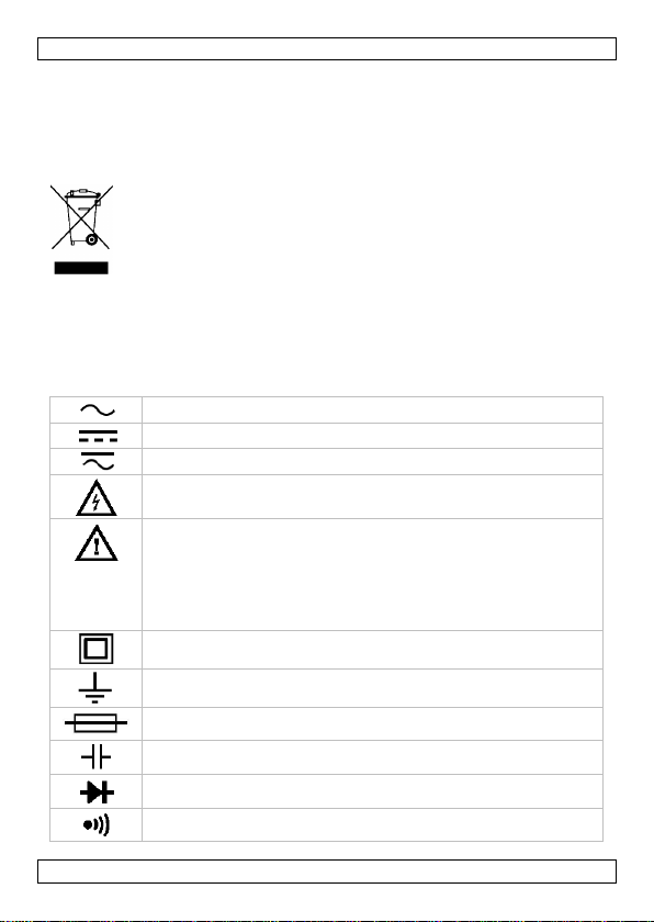
AC (Alternating Current)
DC (Direct Current)
Both AC and DC
Risk of Electric shock. A potentially hazardous voltage is
possible.
Caution: risk of danger, refer to the user manual for safety
information.
Warning: a hazardous condition or action that may result in
injury or death
Caution: condition or action that may result in damage to the
meter or equipment under test
Double insulation (class 2-protection)
Earth
Fuse
Capacitor
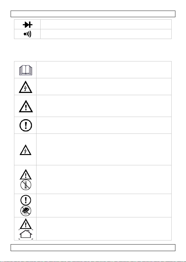
Diode
Continuity
USER MANUAL
1. Introduction
To all residents of the European Union
Important environmental information about this product
This symbol on the device or the package indicates that disposal of
the device after its lifecycle could harm the environment. Do not
dispose of the unit (or batteries) as unsorted municipal waste; it
should be taken to a specialized company for recycling. This device
should be returned to your distributor or to a local recycling
service. Respect the local environmental rules.
If in doubt, contact your local waste disposal authorities.
Thank you for choosing Velleman! Please read the manual thoroughly before
bringing this device into service. If the device was damaged in transit, do
not install or use it and contact your dealer.
2. Used Symbols
V. 01 – 30/08/2016 3 ©Velleman nv
Page 4

DVM892N
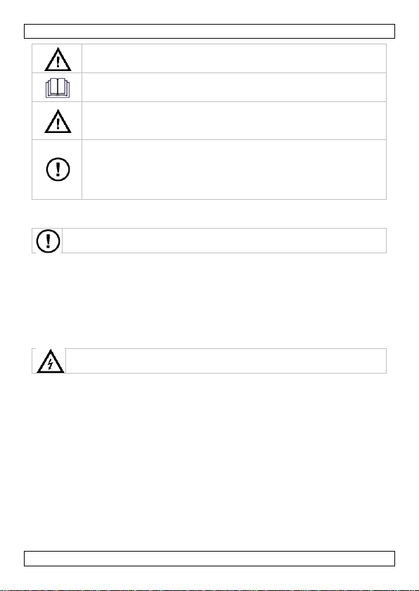
This symbol indicates: Read instructions
Not reading the instructions and manual can lead to damage,
injury or death.
This symbol indicates: Danger
A hazardous condition or action that may result in injury or
death
This symbol indicates: Risk of danger/damage
Risk of a hazardous condition or action that may result in
damage, injury or death
This symbol indicates: Attention; important information
Ignoring this information can lead to hazardous situations.
WARNING: To avoid electrical shock always disconnect the
test leads prior to opening the housing. To prevent fire hazards,
only use fuses with the same ratings as specified in this manual.
Remark: refer to the warning on the battery compartment
Avoid cold, heat and large temperature fluctuations. When
the unit is moved from a cold to a warm location, leave it
switched off until it has reached room temperature. This to
avoid condensation and measuring errors.
Protect this device from shocks and abuse. Avoid brute force
when operating.
Pollution degree 2-device. For indoor use only. Keep this device
away from rain, moisture, splashing and dripping liquids. Not for
industrial use. Refer to §8 Pollution degree.
Keep the device away from children and unauthorised users.
Risk of electric shock during operation. Be very careful
when measuring live circuits.
There are no user-serviceable parts inside the device.
Refer to an authorized dealer for service and/or spare parts.
3. General Guidelines
Refer to the Velleman® Service and Quality Warranty on the last pages
of this manual.
V. 01 – 30/08/2016 4 ©Velleman nv
Page 5
DVM892N
This is an installation category CAT III measuring
instrument. Refer to §7 Overvoltage/installation category.
Read this addendum and the manual thoroughly. Familiarise
yourself with the functions of the device before actually using it.
All modifications of the device are forbidden for safety reasons.
Damage caused by user modifications to the device is not
covered by the warranty.
Only use the device for its intended purpose. Using the device in
an unauthorized way will void the warranty. Damage caused by
disregard of certain guidelines in this manual is not covered by
the warranty and the dealer will not accept responsibility for any
ensuing defects or problems.
There are no user-serviceable parts inside the device.
Refer to an authorized dealer for service and/or spare parts.
Risk of electric shock during operation. Be very careful when
measuring live circuits.
4. Maintenance
Before performing any maintenance activities, disconnect the test leads
from the jacks.
For instructions on replacing battery or fuse, refer to §11 Battery and fuse
replacement.
Do not apply abrasives or solvents to the meter. Use a damp cloth and mild
detergent for cleaning purposes.
5. During Use
Never exceed the limit value for protection. This limit value is listed
separately in the specifications for each range of measurement.
Do not touch unused terminals when the meter is linked to a circuit
which is being tested.
Never use the meter with CAT II installations when measuring voltages
that might exceed the safety margin of 700 V above earth ground.
Never use the meter with CAT III installations when measuring voltages
that might exceed the safety margin of 600 V above earth ground.
Set the range selector at its highest position if the intensity of the
charge to be measured is unknown beforehand.
Disconnect the test leads from the tested circuit before rotating the
range selector in order to change functions.
When carrying out measurements on a TV set or switching power
circuits, always remember that the meter may be damaged by any high
amplitude voltage pulses at test points.
V. 01 – 30/08/2016 5 ©Velleman nv
Page 6

DVM892N
CAT I
A CAT I-rated meter is suitable for measurements on protected
electronic circuits that are not directly connected to mains power,
e.g. electronics circuits, control signals…
Always be careful when working with voltages above 60 VDC or 30 VAC
rms. Keep your fingers behind the probe barriers at all times during
measurement.
Never perform resistance, diode or continuity measurements on live
circuits. Make sure all capacitors in the circuit are depleted.
6. General Description
This device is a battery-operated, hand-held 3 ½ digital multi-meter for
measuring DC and AC voltages, DC current and resistance. It also offers the
possibility of executing continuity tests and of testing diodes and transistors.
The back light is optional.
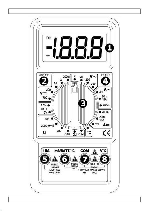
Refer to the illustration on page 2 of this manual:
1. Display
3 ½ digits, 7 segments, LCD: 61 x 26 mm
2. On-off
3. Rotary switch
This switch is used to select functions and desired ranges as well as to
turn the meter on/off.
4. Hold button
In any range, press this button to freeze the last reading. Press again
to unfreeze.
5. "15A" jack
Insert the red test lead in this connector in order to measure a max.
current of 15 A.
6. "mA/BATT/°C" jack
Insert the red test lead in this connector in order to measure current
(except 15 A), the battery and temperature.
7. "COM" jack
Insert the black (negative) test lead.
8. "V" jack
Insert the red (positive) test lead in this connector to measure voltage
and resistance.
7. Overvoltage/Installation Category
DMMs are categorized depending on the risk and severity of transient
overvoltage that might occur at the point of test. Transients are short-lived
bursts of energy induced in a system, e.g. caused by lightning strike on a
power line.
The existing categories according EN 61010-1 are:
V. 01 – 30/08/2016 6 ©Velleman nv
Page 7

DVM892N
CAT
II
A CAT II-rated meter is suitable for measurements in CAT Ienvironments and mono-phase appliances that are connected to the
mains by means of a plug and circuits in a normal domestic
environment, provided that the circuit is at least 10 m apart from a
CAT III- or 20 m apart from a CAT IV-environment. E.g. household
appliances, portable tools…
CAT
III
A CAT III-rated meter is suitable for measurements in CAT I- and
CAT II-environments, as well as for measurements on (fixed) monoor poly-phased appliances which are at least 10 m apart from of a
CAT IV-environment, and for measurements in or on distribution
level equipment (fuse boxes, lighting circuits, electric ovens).
CAT
IV
A CAT IV-rated meter is suitable for measuring in CAT I-, CAT IIand CAT III-environments as well as on the primary supply level.
Note that for all measurements on equipment for which the supply
cables run outdoors (either overhead or underground) a CAT IV
meter must be used.
This device is only suitable for measurements up to 700 V in
CAT II and up to 600 V in CAT III
Pollution
degree 1
No pollution or only dry, nonconductive pollution occurs. The
pollution has no influence. (only to be found in hermetically
sealed enclosures)
Pollution
degree 2
Only nonconductive pollution occurs. Occasionally,
temporary conductivity caused by condensation is to be
expected.(home and office environments fall under this
category)
Warning:
This device was designed in accordance with EN 61010-1 installation
category CAT II 700 V and CAT III 600 V. This implies that certain
restrictions in use apply that are related to voltages and voltage peaks
which can occur within the environment of use. Refer to the table above.
8. Pollution Degree
IEC 61010-1 specifies different types of pollution environments, for which
different protective measures are necessary to ensure safety. Harsher
environments require more protection, and the protection against the
pollution which is to be found in a certain environment depends mainly on
the insulation and the enclosure properties. The pollution degree rating of
the DVM indicates in which environment the device may be used.
V. 01 – 30/08/2016 7 ©Velleman nv
Page 8
DVM892N
Pollution
degree 3
Conductive pollution occurs, or dry nonconductive pollution
occurs that becomes conductive due to condensation that is
to be expected.
(industrial environments and environments exposed to
outside air - but not in contact with precipitation)
Pollution
degree 4
The pollution generates persistent conductivity caused by
conductive dust or by rain or snow. (exposed outdoor
environments and environments where high humidity levels
or high concentrations of fine particles occur)
This device is only suitable for measurements in Pollution
degree class 2 environments.
Warning: This device was designed in accordance with EN 61010-1
pollution degree 2. This implies that certain restrictions in use apply that
are related to pollution which can occur within the environment of use. Refer
to the table above.
9. Specifications
This device is not calibrated when purchased!
Regulations concerning environment of use:
Use this meter only for measurements in CAT I, CAT II and CAT III
environments (see §7)
Use this meter only in a pollution degree 2 environment (see §8)
Ideal working conditions include:
temperature: 0 °C to 40 °C (32 °F to 104 °F)
relative humidity: max. 80 %
altitude: max. 2000 m (6560 ft)
voltage ........................................................................... 700 V
fuse protection
F500 mA/1000 V, 6 x 32 mm
F15 A/1000 V, 6 x 32 mm
power supply ............................................... 1 x 9 V 6LR61 (incl.)
display ............................................................ LCD, 1999 counts
display dimensions ................................................... 61 x 26 mm
over-range .......................................................................... yes
continuity buzzer .................................................................. yes
transistor test ...................................................................... yes
diode test ............................................................................ yes
low-battery indication ........................................................... yes
V. 01 – 30/08/2016 8 ©Velleman nv
Page 9
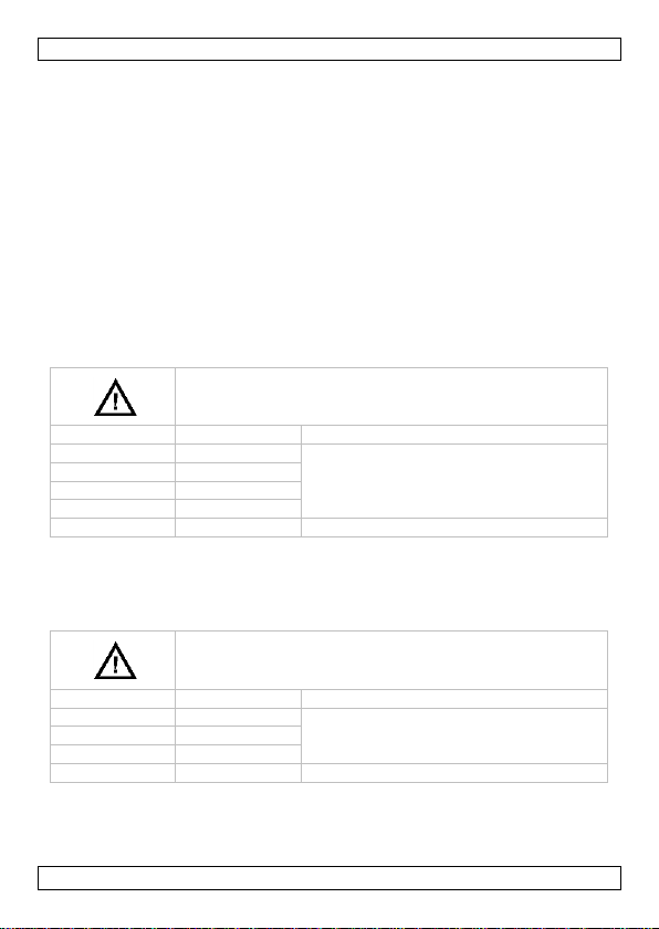
DVM892N
Do not measure circuits that may contain voltages
> 700 V
range
resolution
accuracy
200 mV
0.1 mV
± (0.5 % rdg + 2 digits)
2000 mV
1 mV
20 V
10 mV
200 V
100 mV
700 V
1 V
± (0.8 % rdg + 2 digits)
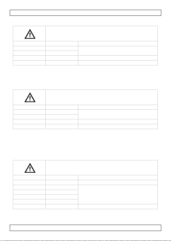
Do not measure circuits that may contain voltages
> 700 V
range
resolution
accuracy
2000 mV
1 mV
± (0.8 % rdg + 3 digits)
20 V
10 mV
200 V
100 mV
700 V
1 V
± (1.2 % rdg + 3 digits)
ranging mode ................................................................ manual
data hold ............................................................................ yes
backlight .............................................................................. no
auto power-off ..................................................................... yes
dimensions ..................................................... 165 x 85 x 37 mm
weight (with battery) ..................................................... ± 215 g
storage environment
temperature ................................................. -20 °C to 60 °C
humidity ............................................................ < 90 % RH
test lead probe (incl.) ..................... CAT III 600 V, 15 A; L = 80 cm
9.1 DC VOLTAGE
Overload protection: 700 V DC or AC rms
Impedance: 10 MΩ
9.2 AC VOLTAGE
Average sensing, calibrated to rms of sine wave
Frequency range: 40-500 Hz
Overload protection: 700 V DC or AC rms
Impedance: 10 MΩ
V. 01 – 30/08/2016 9 ©Velleman nv
Page 10

DVM892N
Do not measure circuits that may contain voltages
> 700 V
range
resolution
accuracy
2 mA
1 µA
± (1.2 % rdg + 2 digits)
20 mA
10 µA
200 mA
100 µA
± (1.5 % rdg + 2 digits)
15 A
10 mA
± (2.0 % rdg + 3 digits)
Do not measure circuits that may contain voltages
> 700 V
range
resolution
accuracy
2 mA
1 µA
± (1.5 % rdg + 3 digits)
20 mA
10 µA
200 mA
100 µA
± (2.0 % rdg + 3 digits)
15 A
10 mA
± (2.5 % rdg + 5 digits)
Do not conduct resistance measurements on live
circuits
range
resolution
accuracy
200 Ω
0.1 Ω
± (1.0 % rdg + 3 digits)
2 kΩ
1 Ω
± (1.0 % rdg + 2 digits)
20 kΩ
10 Ω
200 kΩ
100 Ω
2 MΩ
1 kΩ
20 MΩ
10 kΩ
± (1.5 % rdg + 3 digits)
9.3 DC CURRENT
Overload protection: F500 mA/1000 V, F15 A/1000 V fuse
Note: 15 A up to 10 seconds
9.4 AC CURRENT
Average sensing, calibrated to rms of sine wave
Frequency range: 40-500 Hz
Overload protection: F500 mA/1000 V, F15 A/1000 V fuse
Note: 15 A up to 10 seconds
9.5 RESISTANCE
Overload protection: 700 V DC or AC rms
V. 01 – 30/08/2016 10 ©Velleman nv
Page 11
DVM892N
Do not conduct diode or continuity measurements on
live circuits
range
description
test condition
display reads the
approximate forward
voltage of the diode
forward DC current ± 1 mA
reversed DC voltage ± 3.0 V
built-in buzzer sounds
if resistance < 50 Ω
open-circuit voltage ± 3.0 V
range
accuracy
load current
resolution
1.5 V
± (5.0 % rdg + 5 digits)
100 mA
1 mV
9 V
5 mA
10 mV
range
accuracy
resolution
°C
-50 to 150 °C
± (3 °C + 1 digit)
1 °C
150 to 800 °C
± (3 % + 1 digit)
Do not measure circuits that may contain voltages > 700 V
Use extreme caution when measuring voltages higher than 60 VDC
or 30 VAC rms.
Always place your fingers behind the protective edges of the test
probes while measuring!
9.6 DIODE AND CONTINUITY
Overload protection: 700 V DC or AC rms
9.7 BATTERY TEST
Overload protection: F500 mA/1000 V
9.8 TEMPERATURE
NiCr-NiSi sensor
Overload protection: F500 mA/1000 V
10. Voltage Measurement
V. 01 – 30/08/2016 11 ©Velleman nv
Page 12

DVM892N
Do not measure circuits that may contain voltages > 700 V
Use extreme caution when measuring voltages higher than 60 VDC
or 30 VAC rms.
Always place your fingers behind the protective edges of the test
probes while measuring!
10.1 DC VOLTAGE MEASUREMENT
1. Connect the red test lead to the "V" jack and the black lead to the
"COM" jack.
2. Set the rotary switch in the desired V position. If the voltage to be
measured is unknown beforehand, you should set the range switch in
the highest range position and then reduce gradually until the ideal
resolution is obtained.
3. Connect the test leads to the source being measured.
4. Read the voltage value on the LCD display along with the polarity of
the red lead connection.
10.2 AC VOLTAGE MEASUREMENT
1. Connect the red test lead to the "V" jack and the black test lead to
the "COM" jack.
2. Set the rotary switch in the appropriate V~ position.
3. Connect the test leads to the source to be measured.
4. Read the voltage value on the LCD display.
11. Current Measurement
11.1 DC CURRENT MEASUREMENT
1. Connect the red test lead to the "mA/BATT/°C" jack and the black test
lead to the "COM" jack (switch the red lead to the "15A" jack for
measurements between 200 mA and 15 A).
2. Set the rotary switch in the desired A position.
3. Open the circuit in which the current is to be measured and connect
the test leads to the circuit IN SERIES.
4. Read the current value and the polarity of the red lead connection on
the LCD display
V. 01 – 30/08/2016 12 ©Velleman nv
Page 13
DVM892N
Do not conduct resistance measurements on live circuits. Make sure
all capacitors in the circuit are depleted.
Do not conduct diode or continuity measurements on live circuits.
Make sure all capacitors in the circuit are depleted.
11.2 AC CURRENT MEASUREMENT
1. Connect the red test lead to the "mA/BATT/°C" jack and the black test
lead to the "COM" jack (switch the red lead to the "15A" jack for
measurements between 200 mA and 15 A).
2. Set the rotary switch in the desired A~ position.
3. Open the circuit in which the current is to be measured and connect
the test leads to the circuit IN SERIES.
4. Read the current value and the polarity of the red lead connection on
the LCD display
12. Resistance Measurement
1. Connect the red test lead to the "V" jack and the black test lead to
the "COM" jack (the red lead has a positive polarity "+").
2. Set the rotary switch in the appropriate "" range position.
3. Connect the test leads to the resistor to be measured and read the
LCD display.
4. If the resistance being measured is connected to a circuit, turn off the
power and discharge all capacitors before applying the test probes.
13. Diode and Continuity Testing
1. Connect the red test lead to "V" jack and the black one to the "COM"
jack (the red lead has a positive polarity "+".).
2. Set the rotary switch in the " " position.
3. Connect the red test lead to the anode of the diode to be tested and
the black test lead to the cathode of the diode. The approx. forward
voltage drop of the diode will be displayed. If the connection is
reversed, the display will merely show a "1".
For continuity testing, if continuity exists, the built-in buzzer will
sound.
V. 01 – 30/08/2016 13 ©Velleman nv
Page 14
DVM892N
Do not conduct diode or continuity measurements on live circuits.
Make sure all capacitors in the circuit are depleted.
WARNING: To avoid electrical shock always disconnect the test
leads prior to opening the housing. To prevent fire hazards, only
use fuses with the same ratings as specified in this manual.
Remark: refer to the warning on the battery compartment
There are no user-serviceable parts inside the device.
Refer to an authorized dealer for service and/or spare parts.
Disconnect the test leads from the test points and remove the test
leads from the measuring terminals before replacing the batteries
or fuses.
14. Battery Testing
1. Connect the red test lead to "mA/BATT/°C" and the black one to
"COM".
2. Set the range switch in the desired "1.5V" or "9V" position.
3. Connect the test leads to two points of the source to be tested and
read the LCD display.
15. Temperature Measurement
1. Connect the red banana plug to "mA/BATT/°C" and the black one to
"COM".
2. Set the range switch in the desired "°C" position.
3. Put the probe into the field to be measured and read the LCD display.
16. Battery and Fuse Replacement
When" " is displayed, the battery should be replaced.
Fuses rarely need replacement and blown fuses almost always result
from human error.
To replace the battery or fuse:
Switch of the meter.
Remove the two screws on the bottom of the case and gently open the
housing.
Remove the old battery and insert a new one.
Close the housing and fasten the screws.
Battery: 1x 9 V 6LR61, make sure to respect the polarity
Fuses: F500 mA/1000 V and F15 A/1000 V, 6 x 32 mm
Make sure the meter is closed tight and put the protective edge back in
place before using the meter.
V. 01 – 30/08/2016 14 ©Velleman nv
Page 15
DVM892N
17. Troubleshooting
If the device beeps continuously while measuring continuity, this means that
the F500 mA/1000 V internal fuse is defective. Replace this fuse.
Keep in mind that a low battery level could lead to incorrect measurements.
Replace the battery on a regular basis.
(tip: the reduced luminosity of the backlight/LCD display indicates a low
battery level)
Use this device with original accessories only. Velleman nv cannot
be held responsible in the event of damage or injury resulting from
(incorrect) use of this device. For more info concerning this product
and the latest version of this manual, please visit our website
www.velleman.eu. The information in this manual is subject to
change without prior notice.
© COPYRIGHT NOTICE
The copyright to this manual is owned by Velleman nv. All
worldwide rights reserved. No part of this manual may be copied,
reproduced, translated or reduced to any electronic medium or otherwise
without the prior written consent of the copyright holder.
V. 01 – 30/08/2016 15 ©Velleman nv
Page 16

DVM892N
AC (wisselstroom)
DC (gelijkstroom)
Zowel wissel- als gelijkstroom
Elektrocutiegevaar. Een potentieel gevaarlijke spanning kan
aanwezig zijn.
Opgelet: risico op gevaar, zie de gebruikershandleiding voor
veiligheidsinformatie.
Waarschuwing: gevaarlijke toestand of actie die kan leiden
tot letsel of de dood
Opgelet: een toestand of actie die kan leiden tot schade aan
de meter of het toestel onder test.
Dubbele isolatie (klasse II-bescherming)
Aarding
Zekering
Capaciteit (condensator)
Diode
HANDLEIDING
1. Inleiding
Aan alle ingezetenen van de Europese Unie
Belangrijke milieu-informatie betreffende dit product
Dit symbool op het toestel of de verpakking geeft aan dat, als het
na zijn levenscyclus wordt weggeworpen, dit toestel schade kan
toebrengen aan het milieu. Gooi dit toestel (en eventuele
batterijen) niet bij het gewone huishoudelijke afval; het moet bij
een gespecialiseerd bedrijf terechtkomen voor recyclage. U moet
dit toestel naar uw verdeler of naar een lokaal recyclagepunt
brengen. Respecteer de plaatselijke milieuwetgeving.
Hebt u vragen, contacteer dan de plaatselijke autoriteiten
betreffende de verwijdering.
Dank u voor uw aankoop! Lees deze handleiding grondig door voor u het
toestel in gebruik neemt. Werd het toestel beschadigd tijdens het transport,
installeer het dan niet en raadpleeg uw dealer.
2. Gebruikte symbolen
V. 01 – 30/08/2016 16 ©Velleman nv
Page 17
DVM892N
Continuïteit
Dit symbool betekent: Instructies lezen
Het niet lezen van deze instructies en de handleiding kan leiden
tot beschadiging, letsel of de dood.
Dit symbool betekent: Gevaar
Gevaarlijke toestand of actie die kan leiden tot letsel of de dood
Dit symbool betekent: Risico op gevaar/schade
Risico op het ontstaan van een gevaarlijke toestand of actie die
kan leiden tot schade, letsel of de dood
Dit symbool betekent: Opgelet; belangrijke informatie
Het niet in acht nemen van deze informatie kan leiden tot een
gevaarlijke toestand.
WAARSCHUWING: om elektrische schokken te vermijden,
ontkoppel altijd de meetsnoeren alvorens de behuizing te
openen. Om brand te voorkomen gebruik enkel zekeringen met
dezelfde specificaties zoals aangegeven in de handleiding.
Opmerking: zie waarschuwing op de achterkant van het toestel
Vermijd koude, hitte en grote temperatuurschommelingen.
Als het toestel van een koude naar een warme omgeving
verplaatst wordt, laat het toestel dan eerst voldoende op
temperatuur komen. Dit om meetfouten en condensvorming
te vermijden.
Bescherm tegen schokken. Vermijd brute kracht tijdens de
bediening.
Vervuilingsgraad 2-toestel. Enkel geschikt voor gebruik
binnenshuis! Bescherm het toestel tegen regen, vochtigheid en
opspattende vloeistoffen. Niet geschikt voor industrieel gebruik.
Zie §8 Vervuilingsgraad.
Houd dit toestel uit de buurt van kinderen en onbevoegden.
3. Algemene richtlijnen
Raadpleeg de Velleman® service- en kwaliteitsgarantie achteraan deze
handleiding.
V. 01 – 30/08/2016 17 ©Velleman nv
Page 18
DVM892N
Elektrocutiegevaar tijdens het gebruik van deze
multimeter. Wees voorzichtig tijdens het meten van een circuit
onder spanning.
Er zijn geen onderdelen in het toestel die door de gebruiker
gerepareerd kunnen worden.
Contacteer uw verdeler voor eventuele reserveonderdelen.
Dit is een installatiecategorie CAT III-meetinstrument. Zie
§7 Overspanning-/installatiecategorie.
Lees deze bijlage en de handleiding grondig. Leer eerst de
functies van het toestel kennen voor u het gaat gebruiken.
Om veiligheidsredenen mag u geen wijzigingen aanbrengen aan
het toestel. Schade door wijzigingen die de gebruiker heeft
aangebracht aan het toestel valt niet onder de garantie.
Gebruik het toestel enkel waarvoor het gemaakt is. Bij
onoordeelkundig gebruik vervalt de garantie. De garantie geldt
niet voor schade door het negeren van bepaalde richtlijnen in
deze handleiding en uw dealer zal de verantwoordelijkheid
afwijzen voor defecten of problemen die hier rechtstreeks
verband mee houden.
Er zijn geen onderdelen in het toestel die door de gebruiker
gerepareerd kunnen worden.
Contacteer uw verdeler voor eventuele reserveonderdelen.
Elektrocutiegevaar tijdens het gebruik van deze multimeter.
Wees voorzichtig tijdens het meten van een circuit onder spanning.
4. Onderhoud
Alvorens onderhoudsactiviteiten te beginnen, ontkoppel de meetsnoeren van
de aansluitingen.
Voor informatie over het vervangen van de batterijen en de zekering, zie
§11 Batterijen en zekeringen vervangen.
Gebruik nooit agressieve schuur- of oplosmiddelen. Reinig de meter enkel
met een vochtige doek en een zachte detergent.
5. Gebruik
Overschrijd nooit de grenswaarden. Deze waarden worden vermeld in
de specificaties van elk meetbereik.
Raak geen ongebruikte aansluitingen aan wanneer de meter gekoppeld
is aan een meetcircuit.
Gebruik de meter nooit voor CAT II-installaties bij spanningsmetingen
die de veiligheidsmarge van 700 V boven het massapotentiaal (kunnen)
V. 01 – 30/08/2016 18 ©Velleman nv
Page 19

DVM892N
overschrijden.
Gebruik de meter nooit voor CAT III-installaties bij spanningsmetingen
die de veiligheidsmarge van 600 V boven het massapotentiaal (kunnen)
overschrijden.
Plaats de bereikschakelaar in de hoogste stand indien u de intensiteit
van de belasting niet op voorhand kent.
Ontkoppel de meetsnoeren van het meetcircuit alvorens u aan de
draaischakelaar draait.
Wanneer u metingen uitvoert op een tv of een schakelende voeding,
mag u niet vergeten dat een sterke stroomstoot ter hoogte van de
geteste punten de meter kan beschadigen.
Wees uiterst voorzichtig bij metingen > 60 VDC of > 30 VAC rms. Houd
tijdens metingen uw vingers achter de beschermingsrand van de
meetpennen.
Voer nooit weerstands-, diode- of continuïteitsmetingen uit in circuits
waarop spanning aanwezig is. Zorg ervoor condensatoren in het circuit
volledig ontladen zijn.
6. Algemene omschrijving
Het toestel is een batterijgestuurde, handbediende 3 ½ digitale multimeter.
Met dit apparaat kunt u weerstanden, gelijk- en wisselspanning en
gelijkstroom meten. U kunt continuïteitsmetingen uitvoeren en ook dioden
en transistors meten. Het achtergrondlichtje is optioneel.
Raadpleeg de afbeeldingen op pagina 2 van deze handleiding:
1. Display
3 ½-digits, 7 segmenten, LCD: 61 x 26 mm
2. Aan-uit
3. Draaischakelaar
Wordt gebruikt om de gewenste functie en het bereik in te stellen.
Doet ook dienst als voedingsschakelaar (ON/OFF).
4. HOLD-knop
In elk bereik, druk op deze knop om de laatste weergave op het
scherm te bevriezen. Druk nogmaals om de bevriezing op te heffen.
5. "15A"-bus
Wanneer u het rode meetsnoer aansluit op deze connector, kunt u een
max. stroom meten van 15 A.
6. "mA/BATT/°C"-bus
Sluit het rode meetsnoer aan op deze connector. U kunt nu stroom
(uitgez. 15 A), de batterij en de temperatuur meten.
7. "COM"-bus
Sluit het zwarte (+) meetsnoer aan.
8. "V"-bus
Sluit het rode (+) meetsnoer aan op deze connector. U kunt nu
spanning en weerstand meten.
V. 01 – 30/08/2016 19 ©Velleman nv
Page 20
DVM892N
CAT I
Een CAT I-meter is geschikt voor metingen op beschermde
elektronische circuits die niet rechtstreeks verbonden zijn met het
lichtnet, bv. elektronische schakelingen, stuursignalen…
CAT
II
Een CAT II-meter is geschikt voor metingen in CAT I-omgevingen en
op enkelfasige apparaten die aan het lichtnet gekoppeld zijn door
middel van een stekker en circuits in een normale huiselijke
omgeving, op voorwaarde dat het circuit minstens 10 m verwijderd
is van een CAT III-omgeving, en minstens 20 m van een CAT IVomgeving. Bv. huishoudapparaten, draagbaar gereedschap...
CAT
III
Een CAT III-meter is geschikt voor metingen in CAT I- en CAT IIomgevingen, alsook voor metingen aan enkel- en meerfasige (vaste)
toestellen op meer dan 10 m van een CAT IV-omgeving, en
metingen in of aan distributiekasten (zekeringkasten,
verlichtingscircuits, elektrisch fornuis).
CAT
IV
Een CAT IV-meter is geschikt voor metingen in CAT I-, CAT II- en
CAT III-omgevingen alsook metingen op het primaire toevoerniveau.
Merk op dat voor metingen op toestellen waarvan de toevoerkabels
buitenshuis lopen (zowel boven- als ondergronds) een CAT IV-meter
gebruikt moet worden.
Dit toestel is enkel geschikt voor metingen tot 700 V in CAT II en
tot 600 V in CAT III
7. Overspannings-/installatiecategorie
DMM’s worden opgedeeld volgens het risico op en de ernst van
spanningspieken die kunnen optreden op het meetpunt. Spanningspieken
zijn kortstondige uitbarstingen van energie die geïnduceerd worden in een
systeem door bv. blikseminslag op een hoogspanningslijn.
De bestaande categorieën volgens EN 61010-1 zijn:
Waarschuwing:
Dit toestel is ontworpen conform EN 61010-1 installatie categorie CAT II
700 V en CAT III 600 V. Dit houdt bepaalde gebruiksbeperkingen in die te
maken hebben met spanningen en spanningspieken die kunnen voorkomen
in de gebruiksomgeving. Zie tabel hierboven.
8. Vervuilingsgraad
IEC 61010-1 specificeert verschillende types vervuilingsgraden welke bepaalde
risico’s met zich meebrengen. Iedere vervuilingsgraad vereist specifieke
beschermingsmaatregelen. Omgevingen met een hogere vervuilingsgraad
hebben een betere bescherming nodig tegen mogelijke invloeden van de
verschillende types vervuiling die in deze omgeving kunnen voorkomen. Deze
bescherming hangt hoofdzakelijk af van de isolatie en de eigenschappen van
de behuizing. De opgegeven waarde van vervuilingsgraad geeft aan in welke
omgeving dit apparaat veilig gebruikt kan worden.
V. 01 – 30/08/2016 20 ©Velleman nv
Page 21
DVM892N
Vervuilingsgraad
1
Omgeving zonder, of met enkel droge, niet-geleidende
vervuiling. De voorkomende vervuiling heeft geen
invloed. (komt enkel voor in hermetisch afgesloten
omgevingen)
Vervuilingsgraad
2
Omgeving met enkel niet-geleidende vervuiling.
Uitzonderlijk kan tijdelijke geleiding door condensatie
voorkomen (bv. huishoudelijke- en kantooromgeving)
Vervuilingsgraad
3
Omgeving waar geleidende vervuiling voorkomt, of droge
niet geleidende vervuiling die geleidend kan worden door
condensatie.
(industriële omgevingen en omgevingen die blootgesteld
worden aan buitenlucht zonder rechtstreeks contact met
neerslag)
Vervuilingsgraad
4
Omgeving waar frequent geleidende vervuiling voorkomt,
bv. veroorzaakt door geleidend stof, regen of sneeuw. (in
openlucht en omgevingen met een hoge
vochtigheidsgraad of hoge concentraties fijn stof)
Dit toestel is enkel geschikt voor gebruik in omgevingen
geclassificeerd als vervuilingsgraad 2.
Waarschuwing: Dit toestel is ontworpen conform EN 61010-1
vervuilingsgraad 2. Dit houdt bepaalde gebruiksbeperkingen in die te
maken hebben met de pollutie die kan voorkomen in de gebruiksomgeving.
Zie tabel hierboven.
9. Specificaties
Dit toestel is niet geijkt bij aankoop!
Richtlijnen met betrekking tot de gebruiksomgeving:
Gebruik dit toestel enkel voor metingen aan installatiecategorie CAT II,
CAT III circuits (zie §7)
Gebruik dit toestel alleen in een vervuilingsgraad 2 omgeving (zie §8)
Ideale gebruikscondities:
temperatuur: 0 °C tot 40 °C (32 °F tot 104 °F)
relatieve vochtigheid: max. 80 %
hoogte: max. 2000 m (6560 ft)
spanning ......................................................................... 700 V
beveiliging door zekering
F500 mA/1000 V, 6 x 32 mm
F15 A/1000 V, 6 x 32 mm
voeding ...............................................1x 9 V 6LR61 (meegelev.)
display ...................................................................... LCD, 1999
display-afmetingen ................................................... 61 x 26 mm
buiten meetbereik .................................................................. ja
V. 01 – 30/08/2016 21 ©Velleman nv
Page 22
DVM892N
Meet niet in circuits met spanningen > 700 V
bereik
resolutie
nauwkeurigheid
200 mV
0.1 mV
± (0.5 % v.d. uitlezing + 2 digits)
2000 mV
1 mV
20 V
10 mV
200 V
100 mV
700 V
1 V
± (0.8 % v.d. uitlezing + 2 digits)
Meet niet in circuits met spanningen > 700 V
bereik
resolutie
nauwkeurigheid
2000 mV
1 mV
± (0.8 % v.d. uitlezing + 3 digits)
20 V
10 mV
200 V
100 mV
700 V
1 V
± (1.2 % v.d. uitlezing + 3 digits)
continuïteitszoemer ................................................................ ja
transistortest ......................................................................... ja
diodetest ............................................................................... ja
batterij-laag-indicatie .............................................................. ja
bereikmodus ................................................................. manueel
dataholdfunctie ...................................................................... ja
achtergrondverlichting......................................................... neen
automatische uitschakeling ...................................................... ja
afmetingen ..................................................... 165 x 85 x 37 mm
gewicht (met batterij) .................................................... ± 215 g
opslagtemperatuur
temperatuur ................................................ -20 °C tot 60 °C
vochtigheid ......................................................... < 90 % RH
meetpennen (meegeleverd) ............ CAT III 600 V, 15 A; L = 80 cm
9.1 GELIJKSPANNING
Beveiligd tegen overbelasting: 700 V DC of AC rms
impedantie: 10 MΩ
9.2 WISSELSPANNING
Respons gemiddeld, gekalibreerd in rms van een sinusgolf
Frequentiebereik: 40-500 Hz
Beveiligd tegen overbelasting: 700 V DC of AC rms
impedantie: 10 MΩ
V. 01 – 30/08/2016 22 ©Velleman nv
Page 23
DVM892N
Meet niet in circuits met spanningen > 700 V
bereik
resolutie
nauwkeurigheid
2 mA
1 µA
± (1.2 % v.d. uitlezing + 2 digits)
20 mA
10 µA
200 mA
100 µA
± (1.5 % v.d. uitlezing + 2 digits)
15 A
10 mA
± (2.0 % v.d. uitlezing + 3 digits)
Meet niet in circuits met spanningen > 700 V
bereik
resolutie
nauwkeurigheid
2 mA
1 µA
± (1.5 % v.d. uitlezing + 3 digits)
20 mA
10 µA
200 mA
100 µA
± (2.0 % v.d. uitlezing + 3 digits)
15 A
10 mA
± (2.5 % v.d. uitlezing + 5 digits)
Voer geen weerstandsmetingen uit in circuits waarop
spanning aanwezig is
bereik
resolutie
nauwkeurigheid
200 Ω
0.1 Ω
± (1.0 % v.d. uitlezing + 3 digits)
2 kΩ
1 Ω
± (1.0 % v.d. uitlezing + 2 digits)
20 kΩ
10 Ω
200 kΩ
100 Ω
2 MΩ
1 kΩ
20 MΩ
10 kΩ
± (1.5 % v.d. uitlezing + 3 digits)
9.3 GELIJKSTROOM
Beveiligd tegen overbelasting: F500 mA/1000 V, F15 A/1000 V zekering
Opmerking: 15 A tot 10 seconden
9.4 WISSELSTROOM
Respons gemiddeld, gekalibreerd in rms van een sinusgolf
Frequentiebereik: 40-500 Hz
Beveiligd tegen overbelasting: F500 mA/1000 V, F15 A/1000 V zekering
Opmerking: 15 A tot 10 seconden
9.5 WEERSTAND
Beveiligd tegen overbelasting: 700 V DC of AC rms
V. 01 – 30/08/2016 23 ©Velleman nv
Page 24
DVM892N
Voer geen weerstands-, diode- of continuïteitsmetingen
uit in circuits waarop spanning aanwezig is
bereik
omschrijving
meetvoorwaarde
op de display
verschijnt het
voorwaartse
spanningsverlies van
de diode
voorwaartse gelijkstroom
± 1 mA
DC-sperspanning ± 3.0 V
als de weerstand <
50 Ω, gaat de
ingebouwde zoemer af
open-circuit spanning:
± 3.0 V
bereik
nauwkeurigheid
laststroom
resolutie
1.5 V
± (5.0 % v.d.
uitlezing + 5 digits)
100 mA
1 mV
9 V
5 mA
10 mV
bereik
nauwkeurigheid
resolutie
°C
-50 tot 150 °C
± (3 °C + 1 digit)
1 °C
150 tot 800 °C
± (3 % + 1 digit)
Meet niet in circuits met spanningen > 700 V
Wees uiterst voorzichtig bij metingen hoger dan 60 VDC of 30 VAC
rms.
Houd tijdens metingen uw vingers steeds achter de
beschermingsrand van de meetpennen!
9.6 DIODE EN CONTINUÏTEIT
Beveiligd tegen overbelasting: 700 V DC of AC rms
9.7 BATTERIJ METEN
Beveiligd tegen overbelasting: F500 mA/1000 V
9.8 TEMPERATUUR
NiCr-NiSi-sensor
Beveiligd tegen overbelasting: F500 mA/1000 V
10. Spanning meten
V. 01 – 30/08/2016 24 ©Velleman nv
Page 25
DVM892N
Meet niet in circuits met spanningen > 700 V
Wees uiterst voorzichtig bij metingen hoger dan 60 VDC of 30 VAC
rms.
Houd tijdens metingen uw vingers steeds achter de
beschermingsrand van de meetpennen!
10.1 GELIJKSPANNING METEN
1. Sluit het rode meetsnoer aan op de "V"-bus en het zwarte meetsnoer
op de “COM”-bus.
2. Plaats de draaiknop in de gewenste V stand. Stel de schakelaar in
op het grootste bereik indien de te meten gelijkspanning niet vooraf
gekend is en verminder dan geleidelijk om de ideale resolutie te
bepalen.
3. Sluit de meetsnoeren aan op de meetbron.
4. U kunt nu de intensiteit van de spanning en de polariteit van het rode
meetsnoer aflezen op de LCD-display.
10.2 WISSELSPANNING METEN
1. Sluit het rode meetsnoer aan op de "V"-bus en het zwarte meetsnoer
op de “COM”-bus.
2. Stel het gewenste meetbereik in d.m.v. de draaiknop.
3. Sluit de meetsnoeren aan op de meetbron.
4. U kunt nu de intensiteit van de spanning aflezen op de LCD-display.
11. Stroom meten
11.1 GELIJKSPANNING METEN
1. Sluit het rode meetsnoer aan op de "mA/BATT/°C"-bus en het zwarte
meetsnoer op de “COM”-bus. Sluit het rode meetsnoer aan op de
"15A"-bus voor metingen tussen 200 mA en 15 A).
2. Plaats de draaiknop in de gewenste A stand.
3. Sluit de meetsnoeren IN SERIE aan op het circuit waarvan u de
belasting wilt meten.
4. U kunt nu de intensiteit van de spanning en de polariteit van het rode
meetsnoer aflezen op de LCD-display
V. 01 – 30/08/2016 25 ©Velleman nv
Page 26
DVM892N
Voer geen weerstandsmetingen uit in circuits waarop spanning
aanwezig is. Zorg ervoor condensatoren in het circuit volledig
ontladen zijn.
Voer geen diode- of continuïteitsmetingen uit in circuits waarop
spanning aanwezig is. Zorg ervoor condensatoren in het circuit
volledig ontladen zijn.
11.2 WISSELSPANNING METEN
1. Sluit het rode meetsnoer aan op de "mA/BATT/°C"-bus en het zwarte
meetsnoer op de “COM”-bus. Sluit het rode meetsnoer aan op de
"15A"-bus voor metingen tussen 200 mA en 15 A).
2. Stel het gewenste meetbereik in met de draaiknop.
3. Sluit de meetsnoeren IN SERIE aan op het circuit waarvan u de
belasting wilt meten.
4. U kunt nu de intensiteit van de spanning en de polariteit van het rode
meetsnoer aflezen op de LCD-display
12. Weerstand meten
1. Sluit het rode meetsnoer aan op de "V"-bus en het zwarte testsnoer
op de "COM"-bus (het rode meetsnoer heeft een positieve polariteit
"+").
2. Plaats de draaiknop in de gewenste stand ("").
3. Sluit de meetsnoeren aan op de weerstand en lees de LCD-display.
4. Zorg ervoor dat bij weerstandsmetingen geen spanning meer op het
circuit staat en condensatoren volledig ontladen zijn.
13. Diode en continuïteit meten
1. Sluit het rode meetsnoer aan op de "V"-bus en het zwarte testsnoer
op de "COM"-bus (het rode meetsnoer heeft een positieve polariteit
"+").
2. Plaats de draaiknop in de " " stand.
3. Sluit de rode meetsnoer met de anode van de diode in kwestie en sluit
het zwarte meetsnoer aan op de kathode van de diode. Het
voorwaartse spanningsverlies van de diode verschijnt nu op de display.
Wordt de schakeling omgedraaid, dan verschijnt enkel het cijfer "1" op
de display.
De ingebouwde zoemer zal in werking treden als er continuïteit is
V. 01 – 30/08/2016 26 ©Velleman nv
Page 27

DVM892N
Voer geen diode- of continuïteitsmetingen uit in circuits waarop
spanning aanwezig is. Zorg ervoor condensatoren in het circuit
volledig ontladen zijn.
WAARSCHUWING: om elektrische schokken te vermijden,
ontkoppel altijd de meetsnoeren alvorens de behuizing te openen.
Om brand te voorkomen gebruik enkel zekeringen met dezelfde
specificaties zoals aangegeven in de handleiding.
Opmerking: zie waarschuwing op de achterkant van het toestel
Er zijn geen onderdelen in het toestel die door de gebruiker
gerepareerd kunnen worden.
Contacteer uw verdeler voor eventuele reserveonderdelen.
Ontkoppel de meetsnoeren van het meetcircuit en ontkoppel de
meetsnoeren voor u de batterijen of zekeringen vervangt.
14. Batterijtest
1. Sluit het rode meetsnoer aan op de"mA/BATT/°C"-bus en het zwarte
meetsnoer op de "COM"-bus.
2. Stel het gewenste meetbereik "1.5 V" of "9 V" in.
3. Sluit de meetsnoeren aan op de twee contactpunten en lees de LCD-
display.
15. Temperatuurmeting
1. Sluit de rode banaanstekker aan op de "mA/BATT/°C"-bus en de
zwarte op de "COM"-bus.
2. Plaats de draaiknop in de gewenste stand ("°C").
3. Plaats de sonde in het te meten veld en lees de LCD-display.
16. Batterijen en zekeringen vervangen
Wanneer " " op de display verschijnt, moet u de batterijen
vervangen.
Zekeringen moeten slechts zelden worden vervangen en een
gesprongen zekering is bijna altijd het gevolg van een menselijke fout.
Om de batterij of zekering te vervangen:
Schakel de meter uit.
Verwijder de 2 schroeven aan de onderkant van de behuizing en open
deze voorzichtig.
Verwijder de oude lamp en breng de nieuwe in.
Sluit de behuizing en draai de schroeven vast.
Batterij: 1x 9 V 6LR61, respecteer de polariteit
Zekeringen: F500 mA/1000 V en F15 A/1000 V, 6 x 32 mm
Zorg ervoor dat de meter stevig dichtgeschroefd en plaats de beschermhoes
terug voor u het toestel gebruikt.
V. 01 – 30/08/2016 27 ©Velleman nv
Page 28
DVM892N
17. Problemen en oplossingen
Wanneer het toestel voortdurend piept bij het uitvoeren van een
continuïteitsmeting, betekent dit dat de interne zekering van
F500 mA/1000 V defect is. Vervang deze zekering.
Houd er rekening mee dat een lage batterijspanning kan leiden tot
incorrecte metingen. Vervang de batterij regelmatig.
(tip: U kunt dit ook zien aan de verminderde lichtsterkte van de
achtergrondverlichting/LCD-display)
Gebruik dit toestel enkel met originele accessoires. Velleman nv is
niet aansprakelijk voor schade of kwetsuren bij (verkeerd) gebruik
van dit toestel. Voor meer informatie over dit product en de laatste
versie van deze handleiding, zie www.velleman.eu. De informatie in
deze handleiding kan te allen tijde worden gewijzigd zonder
voorafgaande kennisgeving.
© AUTEURSRECHT
Velleman nv heeft het auteursrecht voor deze handleiding. Alle
wereldwijde rechten voorbehouden. Het is niet toegestaan om deze
handleiding of gedeelten ervan over te nemen, te kopiëren, te vertalen, te
bewerken en op te slaan op een elektronisch medium zonder voorafgaande
schriftelijke toestemming van de rechthebbende.
V. 01 – 30/08/2016 28 ©Velleman nv
Page 29
DVM892N
AC (courant alternatif)
DC (courant continu)
CA et CC
Risque d'électrocution. Possibilité d'une tension
potentiellement dangereuse.
Attention : risque de danger, se reporter aux consignes de
sécurité dans le mode d'emploi.
Avertissement : une situation ou action dangereuse pouvant
causer des blessures ou entraîner la mort
Attention : une situation ou action pouvant endommager le
multimètre ou l'appareil testé
Isolation double (classe de protection II)
Terre
Fusible
Condensateur
MODE D'EMPLOI
1. Introduction
Aux résidents de l'Union européenne
Informations environnementales importantes concernant ce produit
Ce symbole sur l'appareil ou l'emballage indique que l’élimination
d’un appareil en fin de vie peut polluer l'environnement. Ne pas
jeter un appareil électrique ou électronique (et des piles
éventuelles) parmi les déchets municipaux non sujets au tri
sélectif ; une déchetterie traitera l’appareil en question. Renvoyer
l'appareil à votre fournisseur ou à un service de recyclage local. Il
convient de respecter la réglementation locale relative à la protection de
l’environnement.
En cas de questions, contacter les autorités locales pour élimination.
Nous vous remercions de votre achat ! Lire attentivement le présent mode
d'emploi avant la mise en service de l’appareil. Si l'appareil a été
endommagé pendant le transport, ne pas l’installer et consulter votre
revendeur.
2. Symboles utilisés
V. 01 – 30/08/2016 29 ©Velleman nv
Page 30
DVM892N
Diode
Continuité
Ce symbole indique : Lire les instructions
Ne pas lire les instructions ou le mode d'emploi peut causer des
endommagements ou blessures, ou entraîner la mort.
Ce symbole indique : Danger
Une situation ou action dangereuse pouvant causer des
blessures ou entraîner la mort
Ce symbole indique : Risque de
danger/d’endommagement
Risque d’une situation dangereuse ou action pouvant causer des
endommagements ou blessures, ou entraîner la mort
Ce symbole indique : Attention; information importante
La négligence de cette information peut engendrer une situation
dangereuse.
AVERTISSEMENT : Pour éviter les chocs électriques, toujours
déconnecter les cordons de mesure avant d'ouvrir le boîtier.
Pour éviter le risque d'incendie, n'utiliser que des fusibles ayant
les spécifications indiquées dans ce mode d'emploi.
Remarque : se référer à l’avertissement sur le compartiment à
piles
Protéger du froid, de la chaleur et des larges variations de
température. Attendre jusqu’à ce que l’appareil ait atteint la
température ambiante lorsqu’il est déplacé d’un endroit
froid à un endroit chaud, pour éviter la condensation et les
erreurs de mesure.
Protéger l’appareil des chocs et de l'abus. Traiter avec
circonspection pendant l’opération.
Appareil répondant au degré de pollution 2. Uniquement pour
l'usage à l’intérieur. Protéger l'appareil de la pluie, de l'humidité,
d'éclaboussures et des projections d’eau. Ne convient pas à un
usage industriel. Se référer à §8 "Degré de pollution".
3. Directives générales
Se référer à la garantie de service et de qualité Velleman® en fin de ce
mode d'emploi.
V. 01 – 30/08/2016 30 ©Velleman nv
Page 31

DVM892N
Garder l'appareil hors de la portée des enfants et des personnes
non autorisées.
Risque de choc électrique pendant l’opération. Être prudent
lors d’une mesure d’un circuit sous tension.
Il n’y a aucune pièce réparable par l’utilisateur dans l'appareil.
Commander des pièces de rechange éventuelles chez votre
revendeur.
Appareil de mesure répondant à la catégorie d’installation
CAT III. Se référer à 7 "Catégories de
surtension/d’installation.
Lire attentivement cet addenda et le mode d'emploi. Se
familiariser avec le fonctionnement de l'appareil avant de
l'utiliser.
Toute modification est interdite pour des raisons de sécurité. Les
dommages occasionnés par des modifications par le client ne
tombent pas sous la garantie.
N’utiliser l'appareil qu’à sa fonction prévue. Un usage impropre
annule d'office la garantie. La garantie ne se s’applique pas aux
dommages survenus en négligeant certaines directives de ce
mode d'emploi et votre revendeur déclinera toute responsabilité
pour les problèmes et les défauts qui en résultent.
Il n’y a aucune pièce réparable par l’utilisateur dans l'appareil.
Commander des pièces de rechange éventuelles chez votre
revendeur.
Risque de choc électrique pendant l’opération. Être prudent
lors d’une mesure d’un circuit sous tension.
4. Entretien
Déconnecter les cordons de mesure du multimètre avant tout entretien.
Pour informations sur le remplacement des piles ou le fusible, consulter §11
Remplacer les piles et le fusible.
Éviter les produits abrasifs ou agressifs. Nettoyer avec un tissu humide et
un détergent doux.
5. Emploi
Ne jamais dépasser les valeurs limites de protection indiquées. Ces
valeurs de limite sont mentionnées dans les spécifications de chaque
gamme de mesure.
Ne jamais toucher les bornes inutilisées lorsque le mètre est connecté à
un circuit de mesure.
V. 01 – 30/08/2016 31 ©Velleman nv
Page 32

DVM892N
Éviter d'utiliser le mètre pour les installations de la catégorie II lorsque
vous êtes en train de mesurer des tensions qui pourraient surpasser la
marge de sécurité de 700 V au-dessus de la masse.
Éviter d'utiliser le mètre pour les installations de la catégorie III lorsque
vous êtes en train de mesurer des tensions qui pourraient surpasser la
marge de sécurité de 600 V au-dessus de la masse.
Mettre le commutateur de gamme dans sa plus haute position lorsque
vous ne connaissez pas d'avant l'intensité de la charge à mesurer.
Déconnecter les cordons de mesure du circuit avant de déplacer le
sélecteur rotatif.
Lorsque vous effectuez des mesures sur une télévision ou un circuit de
commutation, ne pas oublier que des tensions à hautes amplitudes
peuvent détruire le mètre.
Toujours être prudent lors de mesures de tensions > 60 VCC ou
> 30 VCA rms. Toujours placer vos doigts derrière la protection des
sondes de mesure pendant la mesure.
Ne jamais effectuer des mesures de résistance, de diode ou de
continuité dans un circuit sous tension. S'assurer que tous les
condensateurs dans le circuit sont déchargés.
6. Description générale
Le DVM892N est un multimètre à commande manuelle avec un afficheur
3 ½ digit. Cet appareil vous permet de mesurer des résistances, des
tensions AC et CC et des courants CC. Il est également possible d'exécuter
des tests de continuité ou mesurer des diodes et des transistors. Le
rétroéclairage est optionnel.
Se référer aux illustrations en page 2 de ce mode d'emploi:
1. Afficheur
3 ½ digits, 7 segments, LCD : 61 x 26 mm
2. Marche-arrêt
3. Sélecteur rotatif
Utilisé pour sélectionner les plages et fonctions souhaitées. Ce
commutateur fait aussi fonction d'interrupteur d'alimentation
(ON/OFF).
4. bouton HOLD
Dans toute plage, appuyer ce bouton pour geler le dernier affichage à
l'écran. Appuyer de nouveau pour dégeler l'affichage.
5. Borne "15A"
Connecter le cordon rouge à cette borne. Il est possible de mesurer un
courant max. de 15 A.
6. Borne "mA/BATT/°C"
Connecter le cordon de mesure rouge à cette borne. Ceci vous permet
de mesurer des courants (sauf 15 A), la pile et la température.
V. 01 – 30/08/2016 32 ©Velleman nv
Page 33

DVM892N
CAT I
Un multimètre classé CAT I convient au mesurage de circuits
électroniques protégés non connectés directement au secteur
électrique, p. ex. connexions électroniques circuits, signaux de
contrôle…
CAT
II
Un multimètre classé CAT II convient à la mesure dans un
environnement CAT I, d’appareils monophasés connectés au secteur
électrique par moyen d’une fiche et de circuits dans un
environnement domestique normal, à condition que le circuit se
trouve à une distance minimale de 10 m d’un environnement CAT III
ou de 20 m d’un environnement CAT IV. Par exemple: alimentation
d’appareils ménagers et d’outillage portable,…
CAT
III
Un multimètre classé CAT III convient à la mesure dans un
environnement CAT I et CAT II, ainsi qu'à la mesure d’un appareil
mono- ou polyphasé (fixe) à une distance minimale de 10 m d’un
environnement CAT IV, et à la mesure dans ou d’un boîtier de
distribution (coupe-circuit, circuits d’éclairage, four électrique).
CAT
IV
Un multimètre classé CAT IV convient à la mesure dans un
environnement CAT I, CAT II et CAT III, ainsi qu'à la mesure sur une
arrivée d’énergie au niveau primaire.
Remarque : Tout mesurage effectué sur un appareil dont les câbles
d’alimentation sont en extérieur (câblage de surface ou souterrain)
nécessite un multimètre classé CAT IV.
Cet appareil est uniquement approprié pour mesurer des valeurs
jusqu'à 700 V en CAT II et jusqu'à 600 V en CAT III
7. Borne "COM"
Connecter le cordon de mesure noir (-)
8. Borne "V"
Connecter le cordon de mesure rouge (+) à cette borne. Ceci vous
permet de mesurer des tensions et résistances.
7. Catégories de surtension/d’installation
Les DMM sont classés selon le risque et la sévérité des surtensions
transitoires qui peuvent apparaître sur les points de mesure. Une surtension
transitoire est une augmentation éphémère de la tension induite dans un
système, p. ex. causée par la foudre sur une ligne électrique.
Les catégories existantes selon EN 61010-1 sont :
Avertissement :
Attention: Cet appareil a été conçu selon la directive EN 61010-1, catégorie
de surtension CAT III 700V. Ceci implique que des restrictions d’utilisation
ayant rapport à la tension et les tensions de crête peuvent apparaître dans
l’environnement d’utilisation. Se référer à la table suivante.
V. 01 – 30/08/2016 33 ©Velleman nv
Page 34

DVM892N
Degré de
pollution 1
Absence de pollution ou pollution sèche et non conductrice
uniquement. Pollution influençable. (uniquement dans un
environnement hermétiquement fermé)
Degré de
pollution 2
Pollution non conductrice uniquement. Occasionnellement,
une conductivité éphémère causée par la condensation peut
survenir (environnements domestique et de bureau)
Degré de
pollution 3
Pollution conductrice ou pollution sèche et non conductrice
pouvant devenir conductrice à cause de condensation.
(environnement industriel ou environnement expose au plein
air mais à l’abri des précipitations)
Degré de
pollution 4
Pollution générant une conductivité persistante causée par
de la poussière conductrice, ou par la pluie ou la neige
(environnement expose au plein air, et à des taux
d’humidité et de particules fines élevés).
Cet appareil ne convient qu'à la mesure dans un
environnement ayant un degré de pollution classe 2.
8. Degré de pollution
La norme IEC 61010-1 spécifie les différents types de pollution
environnementale, chaque type nécessitant son propre niveau de protection
afin de garantir la sécurité. Un environnement rude nécessite un niveau de
protection plus sévère. Le niveau de protection adapté à un environnement
précis dépend de l’isolation et de la qualité du boîtier. Le degré de pollution
du DMM indique l’environnement dans lequel le DMM peut être utilisé.
Avertissement : Cet appareil à été conçu selon la norme EN 61010-1,
degré de pollution 2. Ceci implique que des restrictions d’utilisation ayant
rapport à la tension et les tensions de crête peuvent apparaître dans
l’environnement d’utilisation. Se référer à la table suivante.
9. Spécifications
Cet appareil n’est pas étalonné par défaut!
Consignes concernant l’environnement d’utilisation :
N’utiliser ce multimètre que dans un environnement CAT II ou CAT III
(voir §7)
N’utiliser ce multimètre que dans un environnement avec degré de
pollution 2 (voir §8)
Conditions d’utilisation idéales :
température : 0 °C à 40 °C (32 °F à 104 °F)
taux d’humidité relative : max. 80 %
altitude : max. 2000 m (6560 ft)
V. 01 – 30/08/2016 34 ©Velleman nv
Page 35

DVM892N
Ne pas effectuer des mesures dans un circuit pouvant
avoir une tension > 700 V
plage
résolution
précision
200 mV
0.1 mV
± (0.5 % de la lecture + 2 chiffres)
2000 mV
1 mV
20 V
10 mV
200 V
100 mV
700 V
1 V
± (0.8 % de la lecture + 2 chiffres)
tension ........................................................................... 700 V
protection par fusible
F500 mA/1000 V, 6 x 32 mm
F15 A/1000 V, 6 x 32 mm
alimentation ................................................. 1x 9 V 6LR61 (incl.)
afficheur .......................................................... LCD, 1999 points
dimensions de l'afficheur ........................................... 61 x 26 mm
hors plage ........................................................................... oui
continuité du buzzer ............................................................. oui
test de transistor .................................................................. oui
test de diode ....................................................................... oui
indication de pile faible .......................................................... oui
sélection de gamme ...................................................... manuelle
gel d'affichage ..................................................................... oui
rétroéclairage ..................................................................... non
extinction automatique .......................................................... oui
dimensions ..................................................... 165 x 85 x 37 mm
poids (avec pile) ............................................................ ± 215 g
température de stockage
température .................................................. -20 °C à 60 °C
humidité ............................................................ < 90 % RH
sonde de mesure (incl.) .................. CAT III 600 V, 15 A; L = 80 cm
9.1 TENSION CONTINUE
Protection de surcharge : 700 V DC OU VCA rms
Impédance : 10 MΩ
V. 01 – 30/08/2016 35 ©Velleman nv
Page 36

DVM892N
Ne pas effectuer des mesures dans un circuit pouvant
avoir une tension > 700 V
plage
résolution
précision
2000 mV
1 mV
± (0.8 % de la lecture + 3 chiffres)
20 V
10 mV
200 V
100 mV
700 V
1 V
± (1.2 % de la lecture + 3 chiffres)
Ne pas effectuer des mesures dans un circuit pouvant
avoir une tension > 700 V
plage
résolution
précision
2 mA
1 µA
± (1.2 % de la lecture + 2 chiffres)
20 mA
10 µA
200 mA
100 µA
± (1.5 % de la lecture + 2 chiffres)
15 A
10 mA
± (2.0 % de la lecture + 3 chiffres)
Ne pas effectuer des mesures dans un circuit pouvant
avoir une tension > 700 V
plage
résolution
précision
2 mA
1 µA
± (1.5 % de la lecture + 3 chiffres)
20 mA
10 µA
200 mA
100 µA
± (2.0 % de la lecture + 3 chiffres)
15 A
10 mA
± (2.5 % de la lecture + 5 chiffres)
9.2 TENSION ALTERNATIVE
Réponse moyenne, calibrage en rms d'une onde sinusoïdale
Gamme de fréquence : 40-500 Hz
Protection de surcharge : 700 V DC OU VCA rms
Impédance : 10 MΩ
9.3 COURANT CONTINU
Protection de surcharge : fusible F500 mA/1000 V, F15 A/1000 V
Note : 15 A jusqu'à 10 secondes
9.4 COURANT CA
Réponse moyenne, calibrage en rms d'une onde sinusoïdale
Gamme de fréquence : 40-500 Hz
Protection de surcharge : fusible F500 mA/1000 V, F15 A/1000 V
Note : 15 A jusqu'à 10 secondes
V. 01 – 30/08/2016 36 ©Velleman nv
Page 37

DVM892N
Ne pas effectuer des mesures de résistance sur un
circuit sous tension.
plage
résolution
précision
200 Ω
0.1 Ω
± (1.0 % de la lecture + 3 chiffres)
2 kΩ
1 Ω
± (1.0 % de la lecture + 2 chiffres)
20 kΩ
10 Ω
200 kΩ
100 Ω
2 MΩ
1 kΩ
20 MΩ
10 kΩ
± (1.5 % de la lecture + 3 chiffres)
Ne pas effectuer des mesures de diode ou la continuité
sur un circuit sous tension.
plage
description
tester la condition
la perte de tension de
la diode est affichée
courant CC direct ± 1 mA
tension inverse CC ± 3.0 V
le ronfleur intégré
s'active lorsque la
résistance < ± 50 Ω
tension à circuit ouvert
± 3.0 V
plage
précision
courant de
charge
résolution
1.5 V
± (5.0 % de la lecture
+ 5 chiffres)
100 mA
1 mV
9 V
5 mA
10 mV
plage
précision
résolution
°C
-50 à 150 °C
± (3 °C + 1 digit)
1 °C
150 à 800 °C
± (3 % + 1 digit)
9.5 RÉSISTANCE
Protection de surcharge : 700 V DC OU VCA rms
9.6 DIODE ET CONTINUITÉ
Protection de surcharge : 700 V DC OU VCA rms
9.7 TEST DE BATTERIE
Protection de surcharge : F500 mA/1000 V
9.8 TEMPÉRATURE
Capteur NiCr-NiSi
Protection de surcharge : F500 mA/1000 V
V. 01 – 30/08/2016 37 ©Velleman nv
Page 38

DVM892N
Ne pas effectuer des mesures dans un circuit pouvant avoir une
tension > 700 V
Être extrêmement prudent lors d’une mesure d’une tension >
60 VCC ou 30 VCA rms.
Toujours placer vos doigts derrière la protection des sondes de
mesure !
Ne pas effectuer des mesures dans un circuit pouvant avoir une
tension > 700 V
Être extrêmement prudent lors d’une mesure d’une tension
> 60 VCC ou 30 VCA rms.
Toujours placer vos doigts derrière la protection des sondes de
mesure !
10. Mesurer la tension
10.1 MESURER LA TENSION CONTINUE
1. Connecter le cordon de mesure rouge à la borne "V et le cordon de
mesure noir à la borne "COM".
2. Mettre le commutateur rotatif dans la position V souhaitée. Mettre
le commutateur rotatif dans sa position maximum dans le cas où la
tension CC à mesurer est inconnue. Ensuite diminuer la tension
graduellement afin de trouver la résolution idéale.
3. Connecter les cordons de mesure à la source de mesure.
4. L'intensité de la tension et la polarité du cordon rouge se visualisent
sur l'afficheur LCD.
10.2 MESURER LA TENSION ALTERNATIVE
1. Connecter le cordon de mesure rouge à la borne "V" et le cordon noir
à la borne "COM".
2. Mettre le commutateur rotatif dans la position V~ souhaitée.
3. Connecter les cordons de mesure à la source de mesure.
4. La valeur de la charge mesurée se visualise sur l'afficheur LCD.
11. Mesurer le courant
11.1 MESURER LA TENSION CONTINUE
1. Connecter le cordon de mesure rouge à la borne "mA/BATT/°C" et le
cordon de mesure noir à la borne "COM" (connecter le cordon de
mesure rouge à la borne "15A" pour des mesures entre 200 mA et
15 A).
2. Mettre le commutateur rotatif dans la position A souhaitée.
V. 01 – 30/08/2016 38 ©Velleman nv
Page 39

DVM892N
Ne pas effectuer des mesures de résistance sur un circuit sous
tension. S'assurer que tous les condensateurs dans le circuit sont
déchargés.
Ne pas effectuer des mesures de diode ou la continuité sur un
circuit sous tension. S'assurer que tous les condensateurs dans le
circuit soient déchargés.
3. Connecter les cordons de mesure EN SÉRIE à la charge dont vous
voulez mesurer le courant.
4. La valeur de la charge mesurée et la polarité du cordon rouge se
visualisent sur l'afficheur LCD
11.2 MESURER LA TENSION ALTERNATIVE
1. Connecter le cordon de mesure rouge à la borne "mA/BATT/°C" et le
cordon de mesure noir à la borne "COM" (connecter le cordon de
mesure rouge à la borne "15A" pour des mesures entre 200 mA et
15 A).
2. Mettre le commutateur rotatif dans la position A souhaitée.
3. Connecter les cordons de mesure EN SÉRIE à la charge dont vous
voulez mesurer le courant.
4. La valeur de la charge mesurée et la polarité du cordon rouge se
visualisent sur l'afficheur LCD
12. Mesurer la résistance
1. Connecter le cordon de mesure rouge à la borne "V" et le cordon de
mesure noir à la borne "COM" (le cordon rouge a une polarité positive
"+").
2. Mettre le commutateur rotatif sur la gamme de mesure "" appropriée.
3. Connecter les cordons de mesure à la résistance et consulter l'afficheur
LCD.
4. Avant de mesurer la résistance, s'assurer qu'il n'y a plus de tension sur
le circuit et que tous les condensateurs sont déchargés.
13. Test de diode et de continuité
1. Connecter le cordon de mesure rouge à la borne "V" et le cordon de
mesure noir à la borne "COM" (le cordon rouge a une polarité positive
"+".).
2. Mettre le commutateur rotatif dans la position " ".
3. Connecter le cordon rouge à l'anode de la diode en question et
connecter le cordon noir à la cathode de la diode. La perte de tension
de la diode est affichée. Le mètre affichera un "1" si la connexion est
inversée.
Le ronfleur incorporé sera activé en cas de continuité.
V. 01 – 30/08/2016 39 ©Velleman nv
Page 40

DVM892N
Ne pas effectuer des mesures de diode ou la continuité sur un
circuit sous tension. S'assurer que tous les condensateurs dans le
circuit soient déchargés.
AVERTISSEMENT : Pour éviter les chocs électriques, toujours
déconnecter les cordons de mesure avant d'ouvrir le boîtier. Pour
éviter le risque d'incendie, n'utiliser que des fusibles ayant les
spécifications indiquées dans ce mode d'emploi.
Remarque : se référer à l’avertissement sur le compartiment à
piles
Il n’y a aucune pièce réparable par l’utilisateur dans l'appareil.
Commander des pièces de rechange éventuelles chez votre
revendeur.
Éteindre le multimètre et déconnecter les cordons de mesure des
connexions avant de remplacer la pile/le fusible.
14. Test de la pile
1. Connecter le cordon de mesure rouge à la borne "mA/BATT/°C" et le
cordon de mesure noir à la borne "COM".
2. Mettre le commutateur dans la position "1.5 V" ou "9 V".
3. Connecter les cordons de mesure aux deux points de contact et
consulter l'afficheur LCD.
15. Mesure de la température
1. Connecter la fiche banane rouge à la borne "mA/BATT/°C" et la fiche
banane noire à la borne "COM".
2. Mettre le commutateur dans la position "°C".
3. Placer la sonde dans le champ à mesurer et consulter l'afficheur LCD.
16. Remplacer les piles et les fusibles
Lorsque " " s'affiche, remplacer les piles.
Normalement, il n'est pas nécessaire de remplacer un fusible. Il s'agit
presque toujours d'une erreur humaine.
Remplacer la pile ou le fusible :
Éteindre le mètre.
Desserrer les 2 vis de la partie inférieure de l'appareil et ouvrir
soigneusement le boîtier.
Retirer l’ancienne pile et remplacer avec une nouvelle.
Fermer le boîtier et serrer les vis.
Pile: 1x 9 V 6LR61, respecter la polarité
Fusibles: F500 mA/1000 V et F15 A/1000 V, 6 x 32 mm
Refermer le boîtier et placer la gaine protectrice avant d'utiliser le mètre.
V. 01 – 30/08/2016 40 ©Velleman nv
Page 41

DVM892N
17. Problèmes et solutions
Lorsque l'appareil émet un bip sonore en continu pendant la mesure de
continuité, cela signifie que le fusible interne de F500 mA/1000 V est
défectueux. Remplacer le fusible.
Tenir compte qu'un niveau de pile faible pourrait conduire à des mesures
incorrectes. Remplacer les piles régulièrement.
(conseil : la luminosité réduite du rétroéclairage/afficheur LCD indique un
niveau de pile faible)
N'employer cet appareil qu’avec des accessoires d’origine. Velleman
SA ne peut, dans la mesure conforme au droit applicable être tenue
responsable des dommages ou lésions (directs ou indirects) pouvant
résulter de l’utilisation de cet appareil. Pour plus d'informations
concernant cet article et la dernière version de ce mode d'emploi,
consulter notre site www.velleman.eu. Les spécifications et le
continu de ce mode d'emploi peuvent être modifiés sans notification
préalable.
© DROITS D’AUTEUR
SA Velleman est l’ayant droit des droits d’auteur de ce mode
d'emploi. Tous droits mondiaux réservés. Toute reproduction,
traduction, copie ou diffusion, intégrale ou partielle, du contenu de ce mode
d'emploi par quelque procédé ou sur tout support électronique que ce soit
est interdite sans l’accord préalable écrit de l’ayant droit.
V. 01 – 30/08/2016 41 ©Velleman nv
Page 42

DVM892N
AC (« alternating current » o corriente alterna)
DC (« direct current » o corriente continua)
AC y DC
Riesgo de descarga eléctrica. Es posible una tensión
potencialmente peligrosa.
Cuidado: riesgo de peligro, consulte las instrucciones de
seguridad del manual del usuario.
Advertencia: Una situación o acción peligrosa puede causar
lesiones o incluso la muerte
Advertencia: una situación o acción peligrosa puede dañar el
aparato o el equipo a prueba
Aislamiento doble (clase de protección 2)
Conexión a tierra
Fusible
Condensador
Diodo
Continuidad
MANUAL DEL USUARIO
1. Introducción
A los ciudadanos de la Unión Europea
Importantes informaciones sobre el medio ambiente concerniente a
este producto
Este símbolo en este aparato o el embalaje indica que, si tira las
muestras inservibles, podrían dañar el medio ambiente. No tire
este aparato (ni las pilas, si las hubiera) en la basura doméstica;
debe ir a una empresa especializada en reciclaje. Devuelva este
aparato a su distribuidor o a la unidad de reciclaje local. Respete
las leyes locales en relación con el medio ambiente.
Si tiene dudas, contacte con las autoridades locales para residuos.
¡Gracias por elegir Velleman! Lea atentamente las instrucciones del manual
antes de usar el aparato. Si ha sufrido algún daño en el transporte no lo
instale y póngase en contacto con su distribuidor.
2. Símbolos utilizados
V. 01 – 30/08/2016 42 ©Velleman nv
Page 43

DVM892N
Este símbolo indica: Leer las instrucciones
Si no lee las instrucciones o el manual del usuario puede dañar
el aparato o sufrir heridas, incluso morir.
Este símbolo indica: Peligro
Una situación o acción peligrosa puede causar lesiones o incluso
la muerte
Este símbolo indica: Riesgo de peligro/daños.
Una situación o acción peligrosa puede causar daños, lesiones o
incluso la muerte.
Este símbolo indica: Advertencia; información importante
La negligencia de esta información puede causar una situación
peligrosa.
ADVERTENCIA: Para evitar descargas eléctricas, siempre
desconecte las puntas de prueba antes de abrir la caja. Para
evitar cualquier riesgo de incendio, utilice sólo fusibles con las
especificaciones idénticas a las mencionadas en este manual del
usuario.
Observación: Consulte la advertencia del compartimiento de
pilas.
No exponga el aparato al frío, el calor ni grandes
variaciones de temperatura. No conecte el aparato si ha
estado expuesto a grandes cambios de temperatura. Espere
hasta que el aparato llegue a la temperatura ambiente. Esto
para evitar la condensación y los errores de medición.
Proteja el aparato contra choques y golpes. Evite usar excesiva
fuerza durante la operación.
El aparato pertenece al grado de contaminación 2. Sólo es apto
para el uso en interiores. No exponga este equipo a lluvia,
humedad ni a ningún tipo de salpicadura o goteo. No es apto
para el uso industrial. Consulte §8 « Grado de
contaminación ».
Mantenga el aparato lejos del alcance de personas no
capacitadas y niños.
3. Normas generales
Véase la Garantía de servicio y calidad Velleman® al final de este
manual del usuario.
V. 01 – 30/08/2016 43 ©Velleman nv
Page 44

DVM892N
Riesgo de descarga eléctrica durante el funcionamiento.
Sea cuidadoso al efectuar mediciones en un circuito bajo
tensión.
El usuario no habrá de efectuar el mantenimiento de ninguna
pieza.
Contacte con su distribuidor si necesita piezas de recambio.
Este aparato pertenece a la categoría de sobretensión
CAT III. Consulte §7 « Categorías de
sobretensión/instalación.
Lea atentamente este manual del usuario y el apéndice.
Familiarícese con el funcionamiento del aparato antes de
utilizarlo.
Por razones de seguridad, las modificaciones no autorizadas del
aparato están prohibidas. Los daños causados por
modificaciones no autorizadas, no están cubiertos por la
garantía.
Utilice sólo el aparato para las aplicaciones descritas en este
manual Su uso incorrecto anula la garantía completamente. Los
daños causados por descuido de las instrucciones de seguridad
de este manual invalidarán su garantía y su distribuidor no será
responsable de ningún daño u otros problemas resultantes.
El usuario no habrá de efectuar el mantenimiento de ninguna pieza.
Contacte con su distribuidor si necesita piezas de recambio.
Riesgo de descarga eléctrica durante el funcionamiento. Sea
cuidadoso al efectuar mediciones en un circuito bajo tensión.
4. Mantenimiento
Desconecte las puntas de prueba antes de limpiar el aparato o efectuar
trabajos de mantenimiento.
Para informaciones sobre el reemplazo de la pila o el fusible, consulte §11
Reemplazar las pilas y el fusible.
No utilice disolventes y productos abrasivos. Limpie el aparato con un paño
húmedo y un poco detergente.
5. Durante el uso
Nunca exceda los valores límites de protección mencionados. Nunca
exceda los valores límites de protección mencionados en las
especificaciones para cada rango de medición.
Nunca toque terminales no utilizados cuando el multímetro esté
conectado a un circuito a prueba.
V. 01 – 30/08/2016 44 ©Velleman nv
Page 45

DVM892N
No utilice el multímetro para instalaciones de la categoría II al medir
tensiones que podrían sobrepasar la margen de seguridad de 700 V
encima de la masa.
No utilice el multímetro para instalaciones de la categoría III al medir
tensiones que podrían sobrepasar la margen de seguridad de 600 V
encima de la masa.
Coloque el selector de rango en la posición máxima si no conoce el valor
de antemano.
Desconecte las puntas de prueba del circuito analizado antes de
seleccionar otra función u otro rango.
Pueden producirse arcos de tensión en los extremos de las puntas de
prueba durante la comprobación de televisiones o alimentaciones a
conmutación. Tales arcos pueden dañar el multímetro.
Sea extremadamente cuidadoso al medir una tensión > 60 VDC o
30 VAC RMS. ¡Ponga siempre sus dedos detrás de la barrera de
protección!
No mida resistencias, diodos o continuidad en circuitos bajo tensión.
Asegúrese de que todos los condensadores estén completamente
descargados.
6. Descripción general
Este aparato es un multímetro portátil con pantalla LCD de 3 ½ dígitos.
Funciona con pilas y le permite medir tensiones DC y AC, corrientes DC y
resistencias. También es posible efectuar pruebas de transistores, de diodos
y de continuidad. La iluminación es opcional.
Véase la figura en la página 2 de este manual del usuario:
1. pantalla
3 ½ dígitos, 7 segmentos, LCD: 61 x 26 mm
2. On-off (encendido-apagado)
3. Selector giratorio
No sólo se utiliza para seleccionar los rangos y las funciones deseados
sino también para encender o apagar el multímetro (ON/OFF).
4. botón HOLD
En cualquier rango, pulse este botón para bloquear el último valor
medido. Vuelva a pulsar para desbloquear.
5. Borne "15A"
Conecte la punta de prueba roja a esta conexión para medir una
corriente de máx. 15 A.
6. Borne "mA/BATT/°C"
Conecte la punta de prueba roja a esta conexión para medir la
corriente (salvo 15 A), la pila y la temperatura.
7. Borne "COM"
Conecte la punta de prueba negra (negativa).
V. 01 – 30/08/2016 45 ©Velleman nv
Page 46
DVM892N
CAT I
Un multímetro de la categoría CAT I es apto para medir circuitos
electrónicos protegidos no conectados directamente a la red
eléctrica, p.ej. conexiones electrónicos circuitos, señales de control,
etc.
CAT
II
Un DMM de la categoría CAT II es apto para la medición en un
ambiente CAT I, aparatos monofásicos conectados a la red eléctrica
con un conector y circuitos en un ambiente doméstico normal, a
condición de que el circuito esté a una distancia mínima de 10 m de
un ambiente CAT III o 20 m de un ambiente CAT IV. Ejemplo:
alimentación de aparatos electrodomésticos y herramientas
portátiles, etc.
CAT
III
Un DMM de la categoría CAT III no sólo es apto para la medición en
un ambiente CAT I y CAT II, sino también para la medición de un
aparato mono- o polifásico (fijo) a una distancia mínima de 10 m de
un ambiente CAT IV, y para la medición en o de una caja de de
distribución (cortocircuitos, circuitos de iluminación, horno eléctrico).
CAT
IV
Un DMM de la categoría CAT IV es apto tanto para la medición en un
ambiente CAT I, CAT II y CAT III, como para la medición en una
entrada de energía al nivel primario.
Observación: Cualquier medición efectuada en un aparato, cuyos
cables están en el exterior (tanto subterráneo como supraterrenal),
necesita un DMM de la categoría CAT IV.
Este aparato sólo es apto para mediciones de máx. 700 V en
CAT II y máx. 600 V en CAT III
8. Borne "V"
Conecte la punta de prueba roja a esta conexión para medir la tensión
y la resistencia.
7. Categoría de sobretensión/instalación
Los multímetros han sido clasificados según el riesgo y la gravedad de las
sobretensiones transitorias que pueden surgir en las puntas de prueba. Una
sobretensión transitoria es un aumento corto de la tensión inducido por un
sistema, p.ej. caída de un rayo en un de alta tensión.
Las categorías según EN 61010-1 son:
Advertencia:
Este aparato ha sido diseñado según la norma EN 61010-1, categoría de
instalación CAT II 700 V y CAT III 600 V. lo que implica restricciones de uso
referentes a la tensión y las tensiones de cresta pueden aparecer en el
ambiente de uso. Consulte la lista arriba.
V. 01 – 30/08/2016 46 ©Velleman nv
Page 47
DVM892N
Grado de
contaminación
1
Ausencia de contaminación o contaminación seca y sólo no
conductora. Contaminación no influenciable (sólo en un
ambiente herméticamente cerrado).
grado de
contaminación
2
Sólo contaminación no conductora. De vez en cuando,
puede sobrevenir una conducción corta causada por la
condensación (ambiente doméstico y de oficina).
Grado de
contaminación
3
Contaminación conductora o contaminación seca y no
conductora puede volverse conductora a causa de la
condensación
(ambiente industrial o ambiente expuesto al aire libre pero
lejos del alcance de precipitaciones).
Grado de
contaminación
4
Contaminación que genera una conducción persistente
causada por polvo conductor, o por la lluvia o la nieve
(ambiente expuesto al aire libre, y a humedad y partículas
finas elevadas).
Este aparato sólo es apto para mediciones en un ambiente con
un grado de contaminación clase 2.
8. Grado de contaminación (Pollution degree)
La norma IEC 61010-1 especifica los diferentes tipos de contaminación
ambiental. Cada tipo necesita su propio nivel de protección para garantizar
la seguridad. Un ambiente rugoso necesita un nivel de protección más
severo. El nivel de protección adaptado a un ambiente preciso depende del
aislamiento y la calidad de la caja. El grado de contaminación del DVM
indica el ambiente en el que puede ser utilizado.
Advertencia: Este aparato ha sido diseñado según la norma EN 61010-1,
grado de contaminación 2. Lo que implica restricciones de uso con
respecto a la contaminación que puede aparecer en un ambiente de uso.
Consulte la lista arriba.
9. Normas
¡Este aparato no está calibrado por defecto!
Instrucciones sobre el ambiente de uso:
Utilice este aparato sólo en un ambiente CAT I, CAT II y CAT III (véase §7).
Utilice este aparato sólo en un ambiente con un grado de contaminación 2
(véase §8).
Condiciones ideales:
temperatura: de 0 °C a 40 °C (de 32 °F a 104 °F)
humedad relativa: máx. 80 %
altura: máx. 2000 m (6560 ft)
V. 01 – 30/08/2016 47 ©Velleman nv
Page 48

DVM892N
No efectúe mediciones en un circuito que pueda tener
una tensión > 700 V.
alcance
resolución
precisión
200 mV
0.1 mV
± (0.5 % de la lectura + 2 dígitos)
2000 mV
1 mV
20 V
10 mV
200 V
100 mV
700 V
1 V
± (0.8 % de la lectura + 2 dígitos)
tensión ........................................................................... 700 V
protección por fusible
F500 mA/1000 V, 6 x 32 mm
F15 A/1000 V, 6 x 32 mm
alimentación ...................................... 1 x pila 6LR61 de 9 V (incl.)
pantalla ......................................................... LCD, 1999 cuentas
dimensiones de la pantalla ......................................... 61 x 26 mm
sobre rango ........................................................................... sí
avisador acústico de continuidad ............................................... sí
prueba de transistores ............................................................ sí
prueba de diodos .................................................................... sí
indicador de batería baja ......................................................... sí
selección de rango .......................................................... manual
retención de lectura (data hold) ................................................ sí
retroiluminación .................................................................... no
desactivación automática ......................................................... sí
dimensiones ................................................... 165 x 85 x 37 mm
peso (con las pilas) ........................................................ ± 215 g
ambiente de almacenamiento
temperatura .............................................. de -20 °C a 60 °C
humedad ............................................................ < 90 % RH
punta de prueba (incl.) ................... CAT III 600 V, 15 A; L = 80 cm
9.1 TENSIÓN DC
Protección de sobrecarga: 700 V DC o AC rms
Impedancia: 10 MΩ
V. 01 – 30/08/2016 48 ©Velleman nv
Page 49

DVM892N
No efectúe mediciones en un circuito que pueda tener
una tensión > 700 V.
alcance
resolución
precisión
2000 mV
1 mV
± (0.8 % de la lectura + 3 dígitos)
20 V
10 mV
200 V
100 mV
700 V
1 V
± (1.2 % de la lectura + 3 dígitos)
No efectúe mediciones en un circuito que pueda tener
una tensión > 700 V.
alcance
resolución
precisión
2 mA
1 µA
± (1.2 % de la lectura + 2 dígitos)
20 mA
10 µA
200 mA
100 µA
± (1.5 % de la lectura + 2 dígitos)
15 A
10 mA
± (2.0 % de la lectura + 3 dígitos)
No efectúe mediciones en un circuito que pueda tener
una tensión > 700 V.
alcance
resolución
precisión
2 mA
1 µA
± (1.5 % de la lectura + 3 dígitos)
20 mA
10 µA
200 mA
100 µA
± (2.0 % de la lectura + 3 dígitos)
15 A
10 mA
± (2.5 % de la lectura + 5 dígitos)
9.2 TENSIÓN AC
Respuesta media, calibración en rms de una onda sinusoidal
Rango de frecuencias: 40-500 Hz
Protección de sobrecarga: 700 V DC o AC rms
Impedancia: 10 MΩ
9.3 CORRIENTE DC
Protección de sobrecarga: fusible F500 mA/1000 V, F15 A/1000 V
Observación: 15 A máx. 10 segundos
9.4 CORRIENTE AC
Respuesta media, calibración en rms de una onda sinusoidal
Rango de frecuencias: 40-500 Hz
Protección de sobrecarga: fusible F500 mA/1000 V, F15 A/1000 V
Observación: 15 A máx. 10 segundos
V. 01 – 30/08/2016 49 ©Velleman nv
Page 50

DVM892N
Nunca efectúe mediciones de resistencia de un circuito
bajo tensión.
alcance
resolución
precisión
200 Ω
0.1 Ω
± (1.0 % de la lectura + 3 dígitos)
2k Ω
1 Ω
± (1.0 % de la lectura + 2 dígitos)
20 kΩ
10 Ω
200 kΩ
100 Ω
2 MΩ
1 kΩ
20 MΩ
10 kΩ
± (1.5 % de la lectura + 3 dígitos)
No mida el diodo ni la continuidad en un circuito bajo
tensión.
alcance
descripción
condiciones de prueba
El multímetro
visualizará la tensión
directa aproximativa
del diodo.
corriente directa DC ± 1 mA
tensión inversa DC ± 3.0 V
señal acústica en caso
de una resistencia
< 50 Ω
tensión de circuito abierto
± 3.0 V
alcance
precisión
corriente de
carga
resolució
n
1.5 V
± (5.0 % de la lectura
+ 5 dígitos)
100 mA
1 mV
9 V
5 mA
10 mV
alcance
precisión
resolución
°C
de -50 a 150 °C
± (3 °C + 1 dígito)
1 °C
de -150 a 800 °C
± (3 % + 1 dígito)
9.5 RESISTENCIA
Protección de sobrecarga: 700 V DC o AC rms
9.6 PRUEBA DE DIODOS Y CONTINUIDAD
Protección de sobrecarga: 700 V DC o AC rms
9.7 SOMETER LA BATERÍA A PRUEBA
Protección de sobrecarga: F500 mA/1000 V
9.8 TEMPERATURA
Sensor NiCr-NiSi
Protección de sobrecarga: F500 mA/1000 V
V. 01 – 30/08/2016 50 ©Velleman nv
Page 51

DVM892N
No efectúe mediciones en un circuito que pueda tener una tensión
> 700 V.
Sea extremadamente cuidadoso al medir una tensión > 60 VCC o >
30 VCA rms.
¡Ponga siempre sus dedos detrás de la barrera de protección!
No efectúe mediciones en un circuito que pueda tener una tensión
> 700 V.
Sea extremadamente cuidadoso al medir una tensión > 60 VDC o >
30 VAC rms.
¡Ponga siempre sus dedos detrás de la barrera de protección!
10. Medir la tensión
10.1 MEDIR LA TENSIÓN DC
1. Conecte la punta de prueba roja al borne "V" y la punta de prueba
negra al borne "COM".
2. Seleccione el rango de medición apropiado (V) con el selector giratorio
3. Conecte las puntas de prueba a la fuente que desea medir.
4. El valor medido y la polaridad de la punta de prueba roja se
10.2 MEDIR LA TENSIÓN AC
1. Conecte la punta de prueba roja al borne "V" y la punta de prueba
2. Seleccione el rango de medición apropiado (V~) con el selector
3. Conecte las puntas de prueba a la fuente que desea medir.
4. El valor medido se visualizará en la pantalla LCD.
. Coloque el selector de rango en la posición máxima si no conoce
la tensión que quiere medir de antemano. Luego, disminuya la tensión
gradualmente hasta que encuentre la resolución ideal.
visualizarán en la pantalla LCD.
negra al borne "COM".
giratorio.
11. Medir la corriente
11.1 MEDIR LA CORRIENTE DC
1. Conecte la punta de prueba roja al borne "mA/BATT/°C" y la punta de
prueba negra al borne "COM" (Conecte la punta de prueba roja al
borne "15A" para mediciones entre 200 mA y 15 A).
2. Seleccione el rango de medición apropiado A con el selector giratorio.
3. Conecte las puntas de prueba EN SERIE al circuito del que quiere
medir la corriente.
4. El valor medido y la polaridad de la punta de prueba roja se
visualizarán en la pantalla LCD.
V. 01 – 30/08/2016 51 ©Velleman nv
Page 52

DVM892N
Nunca efectúe mediciones de resistencia en un circuito bajo tensión.
Asegúrese de que todos los condensadores estén completamente
descargados.
No mida el diodo ni la continuidad en un circuito bajo tensión.
Asegúrese de que todos los condensadores estén completamente
descargados.
11.2 Medir la corriente AC
1. Conecte la punta de prueba roja al borne "mA/BATT/°C" y la punta de
prueba negra al borne "COM" (Conecte la punta de prueba roja al
borne "15A" para mediciones entre 200 mA y 15 A).
2. Seleccione el rango de medición apropiado A~ con el selector giratorio.
3. Conecte las puntas de prueba EN SERIE al circuito del que quiere
medir la corriente.
4. El valor medido y la polaridad de la punta de prueba roja se
visualizarán en la pantalla LCD.
12. Medir la resistencia
1. Conecte la punta de prueba roja al borne "V" y la punta de prueba
negra al borne "COM" (la punta de prueba roja tiene una polaridad
positiva "+").
2. Seleccione el rango de medición apropiado () con el selector
giratorio.
3. Conecte las puntas de prueba a la resistencia y consulte la pantalla
LCD.
4. Asegúrese de que al circuito a prueba se le haya interrumpido toda la
energía y cualquier condensador esté totalmente descargado, antes de
efectuar la medición.
13. Prueba de diodos y continuidad
1. Conecte la punta de prueba roja al borne "V" y la punta de prueba
negra al borne "COM" (la punta de prueba roja tiene una polaridad
positiva "+".).
2. Ponga el selector giratorio en la posición " ".
3. Conecte la punta de prueba roja al ánodo y la punta de prueba negra
al cátodo del diodo. El multímetro visualizará la tensión directa
aproximativa del diodo. Se visualizará “1” si se ha invertido la
conexión.
Para la prueba de continuidad, el zumbador incorporado emitirá una
señal acústica si hay continuidad.
V. 01 – 30/08/2016 52 ©Velleman nv
Page 53

DVM892N
No mida el diodo ni la continuidad en un circuito bajo tensión.
Asegúrese de que todos los condensadores estén completamente
descargados.
ADVERTENCIA: Para evitar descargas eléctricas, siempre
desconecte las puntas de prueba antes de abrir la caja. Para evitar
cualquier riesgo de incendio, utilice sólo fusibles con las
especificaciones idénticas a las mencionadas en este manual del
usuario.
Observación: Consulte la advertencia del compartimiento de pilas.
El usuario no habrá de efectuar el mantenimiento de ninguna pieza.
Contacte con su distribuidor si necesita piezas de recambio.
Desconecte el aparato de la red eléctrica y quite las puntas de
prueba antes de reemplazar las pilas o los fusibles.
14. Someter la pila a prueba
1. Conecte la punta de prueba roja al borne "mA/BATT/°C" y la punta de
prueba negra al borne "COM".
2. Coloque el selector giratorio en la posición "1.5V" o "9V" deseada.
3. Conecte las puntas de prueba a dos puntos de la fuente que quiere
probar. El valor se visualizará en la pantalla LCD.
15. Medición de la temperatura
1. Conecte el conector banana rojo al borne "mA/BATT/°C" y el conector
banana negro al borne "COM".
2. Coloque el selector giratorio en la posición "°C" deseada.
3. Ponga la sonda en el campo que quiere medir. El valor se visualizará
en la pantalla LCD.
16. Reemplazar la pila y el fusible
Reemplace la batería en cuanto se visualice el símbolo " ".
Normalmente, no es necesario reemplazar un fusible. Sólo se funden a
causa de un error de uso.
Para reemplazar la pila o el fusible:
Apague el multímetro.
Desatornille los dos tornillos de la parte inferior y abra cuidadosamente
la caja.
Quite la pila agotada e introduzca la nueva.
Cierre la carcasa y apriete los tornillos.
La pila: 1x 9 V 6LR61. Controle la polaridad.
Fusibles: F500 mA/1000 V y F15 A/1000 V, 6 x 32 mm
Antes de utilizar el multímetro, verifique que el panel trasero esté bien
cerrado.
V. 01 – 30/08/2016 53 ©Velleman nv
Page 54

DVM892N
17. Solución de problemas
Si el aparato emite una señal acústica ininterrumpida mientras está
midiendo la continuidad, significará que el fusible interno de
F500 mA/1000 V está defectuoso. Reemplace el fusible.
Un nivel de pila baja podría causar mediciones incorrectas. Reemplace la
pila regularmente.
(consejo: La luminosidad reducida de la retroiluminación/la pantalla LCD
indicará un nivel de pila baja).
Utilice este aparato sólo con los accesorios originales. Velleman NV
no será responsable de daños ni lesiones causados por un uso
(indebido) de este aparato. Para más información sobre este
producto y la versión más reciente de este manual del usuario, visite
nuestra página www.velleman.eu. Se pueden modificar las
especificaciones y el contenido de este manual sin previo aviso.
© DERECHOS DE AUTOR
Velleman NV dispone de los derechos de autor para este manual del
usuario. Todos los derechos mundiales reservados. Está estrictamente
prohibido reproducir, traducir, copiar, editar y guardar este manual del
usuario o partes de ello sin el consentimiento previo por escrito del
propietario del copyright.
V. 01 – 30/08/2016 54 ©Velleman nv
Page 55

DVM892N
AC (Wechselstrom)
DC (Gleichstrom)
Sowohl Wechsel- als auch Gleichstrom
Stromschlaggefahr. Es kann eine potentiell gefährliche
Spannung anliegen.
Achtung: Risiko auf Gefahr, lesen Sie die
Sicherheitshinweise.
Achtung: Eine unvorsichtige Nutzung dieses Gerätes kann zu
Verletzungen oder zum Tod führen.
Achtung: Eine unvorsichtige Nutzung kann das Multimeter
oder das Gerät, das Sie testen möchten, beschädigen.
Doppelisolation (Schutzklasse 2)
Erde, Masse
Sicherung
Kondensator
BEDIENUNGSANLEITUNG
1. Einführung
An alle Einwohner der Europäischen Union
Wichtige Umweltinformationen über dieses Produkt
Dieses Symbol auf dem Produkt oder der Verpackung zeigt an, dass
die Entsorgung dieses Produktes nach seinem Lebenszyklus der
Umwelt Schaden zufügen kann. Entsorgen Sie die Einheit (oder
verwendeten Batterien) nicht als unsortierter Hausmüll; die Einheit
oder verwendeten Batterien müssen von einer spezialisierten Firma
zwecks Recycling entsorgt werden. Diese Einheit muss an den
Händler oder ein örtliches Recycling-Unternehmen retourniert werden.
Respektieren Sie die örtlichen Umweltvorschriften.
Falls Zweifel bestehen, wenden Sie sich für Entsorgungsrichtlinien
an Ihre örtliche Behörde.
Vielen Dank, dass Sie sich für Velleman entschieden haben! Lesen Sie diese
Bedienungsanleitung vor Inbetriebnahme sorgfältig durch. Überprüfen Sie,
ob Transportschäden vorliegen. Sollte dies der Fall sein, verwenden Sie das
Gerät nicht und wenden Sie sich an Ihren Händler.
2. Verwendete Symbole
V. 01 – 30/08/2016 55 ©Velleman nv
Page 56

DVM892N
Diode
Durchgang
Dieses Symbol bedeutet Bitte lesen Sie die Hinweise.
Das nicht Lesen der Hinweise und der Bedienungsanleitung kann
Schäden, Verletzungen oder den Tod verursachen.
Dieses Symbol bedeutet Gefahr
Eine unvorsichtige Nutzung dieses Gerätes kann zu Verletzungen
oder zum Tod führen.
Dieses Symbol bedeutet Risiko auf Gefahr/Schäden
Eine unvorsichtige Nutzung dieses Gerätes kann zu
Beschädigungen, Verletzungen oder zum Tod führen.
Dieses Symbol bedeutet Achtung; wichtige Informationen
Befolgen Sie diese Information nicht, so kann dies zu einer
gefährlichen Situation führen
WARNUNG: Um Stromschläge zu vermeiden, trennen Sie die
Messleitungen immer vom Messkreis und vom Gerät, bevor
Sie das Gehäuse öffnen. Um Brandgefahr zu vermeiden,
verwenden Sie nur Sicherungen des gleichen Typs (siehe
technische Daten).
Bemerkung: siehe die Bemerkung, die sich auf dem
Batteriefach befindet
Setzen Sie das Gerät keiner Kälte, Hitze und großen
Temperaturschwankungen aus. Nehmen Sie das Gerät nicht
sofort in Betrieb, nachdem es von einem kalten in einen
warmen Raum gebracht wurde. Lassen Sie das Gerät
solange ausgeschaltet, bis es die Zimmertemperatur
erreicht hat. So vermeiden Sie Kondensation und
Messfehler.
Vermeiden Sie Erschütterungen. Vermeiden Sie rohe Gewalt
während der Bedienung.
3. Allgemeine Richtlinien
Siehe Velleman® Service- und Qualitätsgarantie am Ende dieser
Bedienungsanleitung.
V. 01 – 30/08/2016 56 ©Velleman nv
Page 57

DVM892N
Gerät mit Verschmutzungsgrad 2. Eignet sich nur für die
Anwendung im Innenbereich! Schützen Sie das Gerät vor Regen
und Feuchte. Setzen Sie das Gerät keiner Flüssigkeit wie z.B.
Tropf- oder Spritzwasser, aus. Eignet sich nicht für industrielle
Anwendung. Siehe §8 Verschmutzungsgrad.
Halten Sie Kinder und Unbefugte vom Gerät fern.
Stromschlaggefahr während des Gebrauchs des
Multimeters. Seien Sie vorsichtig beim Messen von einem
unter Strom stehenden Kreis.
Es gibt keine zu wartenden Teile.
Bestellen Sie eventuelle Ersatzteile bei Ihrem Fachhändler.
Das Gerät gehört zur Installationskategorie CAT III. Siehe
§7 Überspannungs-/Installationskategorie.
Lesen Sie das Addendum und diese Bedienungsanleitung
sorgfältig durch. Nehmen Sie das Gerät erst in Betrieb, nachdem
Sie sich mit seinen Funktionen vertraut gemacht haben.
Eigenmächtige Veränderungen sind aus Sicherheitsgründen
verboten. Bei Schäden verursacht durch eigenmächtige
Änderungen erlischt der Garantieanspruch.
Verwenden Sie das Gerät nur für Anwendungen beschrieben in
dieser Bedienungsanleitung. sonst kann dies zu Schäden am
Produkt führen und erlischt der Garantieanspruch. Bei Schäden,
die durch Nichtbeachtung der Bedienungsanleitung verursacht
werden, erlischt der Garantieanspruch. Für daraus resultierende
Folgeschäden übernimmt der Hersteller keine Haftung.
Es gibt keine zu wartenden Teile.
Bestellen Sie eventuelle Ersatzteile bei Ihrem Fachhändler.
4. Wartung
Trennen Sie die Messleitungen vor dem Warten oder Reinigen von jeder
Spannungsquelle.
Informationen über den Batterie- und Sicherungswechsel finden Sie unter
§11 Batterie- und Sicherungswechsel.
Benutzen Sie niemals aggressive Scheuer- oder Lösungsmittel. Verwenden
Sie zur Reinigung ein feuchtes Tuch und ein bisschen Reinigungsmittel.
V. 01 – 30/08/2016 57 ©Velleman nv
Page 58

DVM892N
Stromschlaggefahr während des Gebrauchs des Multimeters.
Seien Sie vorsichtig beim Messen von einem unter Strom stehenden
Kreis.
5. Während des Gebrauchs
Überschreiten Sie nie die Grenzwerte. Diese Werte werden jedes Mal
separat in den technischen Daten jedes Messbereichs erwähnt.
Berühren Sie keine freien Eingangsbuchsen, wenn die Schaltungen nicht
spannungslos sind.
Verwenden Sie das Multimeter niemals für Messungen, die die
Spannung zwischen den Anschlusspunkten des Messgeräts und
Erdpotential 700 in CAT II überschreiten.
Verwenden Sie das Multimeter niemals für Messungen, die die
Spannung zwischen den Anschlusspunkten des Messgeräts und
Erdpotential 600 V in CAT III überschreiten.
Stellen Sie den Bereichsschalter in den höchsten Stand, wenn Sie die
Belastungsintensität nicht im voraus kennen.
Entfernen Sie die Messleitungen von der geprüften Schaltung, ehe Sie
den Funktionsschalter verstellen.
Wenn Sie einen Fernseher oder eine getaktete Speisung messen, dürfen
Sie nicht vergessen, dass ein starker Stromstoß in den geprüften
Punkten das Meter beschädigen können.
Seien Sie vorsichtig wenn Sie mit Spannungen über 60 VDC oder
30 VAC rms arbeiten. Halten Sie die Finger während der Messungen
hinten den Prüfspitzen!
Führen Sie nie Widerstands-, Diodenmessungen oder
Durchgangsprüfungen an spannungsführenden Schaltungen durch.
Beachten Sie, dass alle Kondensatoren völlig entladen sind.
6. Allgemeine Beschreibung
Dieses Gerät ist ein batteriebetriebenes 3 ½stelliges DigitalHandmultimeter. Mit diesem Gerät können Sie Widerstand, Gleich-,
Wechselspannung und Gleichstrom messen. Dieses Multimeter ermöglicht
nicht nur Durchgangsprüfungen, sondern auch Dioden- und Transistortests.
Die Hintergrundbeleuchtung ist optional.
Siehe Abbildung, Seite 2 dieser Bedienungsanleitung:
1. Display
3 ½-stellig, 7 Segmente, LCD: 61 x 26 mm
2. Ein-aus
3. Drehschalter
Mit diesem Schalter stellen Sie die gewünschte Funktion und den
gewünschten Bereich ein und können Sie das Gerät ein- und
abschalten.
V. 01 – 30/08/2016 58 ©Velleman nv
Page 59

DVM892N
CAT I
Ein CAT I-Multimeter eignet sich für Messungen an Stromkreisen, die
nicht direkt mit dem Netz verbunden sind, z.B. batteriebetriebene
Geräte usw.
CAT
II
Ein CAT II-Multimeter eignet sich für Messungen in CAT IUmgebungen und an einphasigen Geräten, die über einen Stecker
mit dem Netz verbunden sind, unter der Bedingung, dass der Kreis
mindestens 10 m von einer CAT III-Umgebung und min. 20 m einer
CAT IV-Quelle entfernt ist. Zum Beispiel, Haushaltsgeräte, tragbare
Geräte, usw.
CAT
III
Ein CAT III-Multimeter eignet sich nicht nur für Messungen in CAT I
und CAT II-Umgebungen sondern auch für Messungen an ein- oder
mehrphasigen Geräten unter der Bedingung, dass der Kreis
mindestens 10 m von einer CAT IV-Umgebung entfernt ist und für
Messungen in der Gebäudeinstallation, (z.B. Steckdosen,
Sicherungskasten, Kontrolleinheiten usw.).
CAT
IV
Ein CAT IV-Multimeter eignet sich nicht nur für Messungen in CAT I,
CAT II und CAT III-Umgebungen, sondern auch für Messungen auf
Primärversorgungsebene.
4. Taste HOLD
In jedem Bereich, drücken Sie diese Taste, um den letzten Messwert
festzuhalten. Drücken Sie wieder, um den Messwert wieder
freizugeben.
5. "15A"-Anschlussbuchse
Stecken Sie die rote (positive) Messleitung in diese Buchse, um einen
max. Strom bis max. 15 A zu messen.
6. "mA/BATT/°C"-Anschlussbuchse
Stecken Sie die rote Messleitung in diese Buchse, um Strom (außer
15 A), die Batterie und die Temperatur zu messen.
7. "COM"-Anschlussbuchse
Verbinden Sie die schwarze (negative) Messleitung.
8. "V"-Anschlussbuchse
Stecken Sie die rote Messleitung (+) in diese Buchse, um Spannung
und Widerstand zu messen.
7. Überspannungs-/Messkategorie
Die Multimeter werden gemäß Risiko und Ernst der Spannungsspitzen, die
an dem Messpunkt auftreten können, aufgeteilt. Spannungsspitzen sind
kurze Ausbrüche von Energie, die in einem System durch z.B. Blitzschlag an
einem Hochspannungskabel, induziert werden.
Die bestehenden Kategorien gemäß EN 61010-1 sind:
V. 01 – 30/08/2016 59 ©Velleman nv
Page 60
DVM892N
Bemerken Sie, dass Sie für Messungen an Geräten, deren
Zuleitungskabel sich außer Haus befinden (sowohl ober- als
unterirdisch), ein CAT IV-Multimeter verwenden müssen.
Das Gerät eignet sich nur für Messungen von max. 700 V in
CAT II und max. 600 V in CAT III
Verschmutzungsgrad
1
Es gibt keine oder nur trockene, nichtleitende
Verschmutzung. Die Verschmutzung hat also keinen
Einfluss (kommt nur in hermetisch abgeschlossenen
Räumen vor).
Verschmutzungsgrad
2
Es gibt nur nichtleitende Verschmutzung.
Gelegentlich muss mit vorübergehender Leitfähigkeit
durch Kondensation gerechnet werden (häusliche und
Büro-Umgebungen gehören zu dieser Kategorie)
Verschmutzungsgrad
3
Es tritt leitfähige Verschmutzung oder trockene,
nichtleitende Verschmutzung, die leitfähig wird, da
Kondensation entsteht, auf
(industrielle Umgebungen und Umgebungen, die der
frischen Luft ausgesetzt werden, aber nicht in
direktem Kontakt mit Regen kommen).
Verschmutzungsgrad
4
Die Verschmutzung erzeugt eine bleibende
Leitfähigkeit, die durch einen leitfähigen Staub,
Regen oder Schnee (Außenumgebungen, die hohen
Feuchtigkeitsniveaus oder hohen Konzentrationen mit
feinen Teilen ausgesetzt werden) verursacht wird.
Warnung:
Dieses Gerät wurde gemäß der EN 61010-1 Installationskategorie CAT II
700 V und CAT III 600 V entworfen. Dies beinhaltet bestimmte
Anwendungsbeschränkungen in Bezug auf Spannungen und
Spannungsspitzen, die in der Gebrauchsumgebung, vorkommen können.
Siehe Liste oben.
8. Verschmutzungsgrad (Pollution degree)
IEC 61010-1 spezifiziert verschiedene Umgebungstypen, die sich auf den
anwesenden Verschmutzungsgrad stützen. Für diesen Verschmutzungsgrad
gelten verschiedene Schutzmaßnahmen, die Sicherheit gewährleisten.
Rauere Umgebungen erfordern einen besseren Schutz und den Schutz vor
Verschmutzung, der in einer bestimmten Umgebung gilt, hängt in hohem
Maße von der Isolierung und der Qualität des Gehäuses ab. Diese
Klassifizierung zeigt an, in welcher Umgebung Sie das Gerät verwenden
dürfen.
Warnung: Das Gerät wurde gemäß EN 61010-1 Verschmutzungsgrad 2
entworfen. Dies beinhaltet bestimmte Anwendungsbeschränkungen in Bezug
V. 01 – 30/08/2016 60 ©Velleman nv
Page 61

DVM892N
Das Gerät eignet sich nur für die Anwendung in Umgebungen
mit Verschmutzungsgrad 2.
auf die Verschmutzungsgrad, die in der Gebrauchsumgebung, vorkommen
kann. Siehe Liste oben.
9. Technische Daten
Dieses Gerät ist bei Ankauf nicht kalibriert!
Normen:
Verwenden Sie das Gerät nur für Messungen an Überspannungs/Messkategorie CAT I, CAT II und CAT III-Kreisen (siehe §7).
Verwenden Sie das Gerät nur einer Umgebung mit Verschmutzungsgrad 2
(siehe §8).
Ideale Umgebungstemperatur:
Temperatur: 0 °C bis 40 °C (32 °F bis 104 °F)
relative Feuchte: max. 80 %
Höhe: max. 2000 m (6560 ft)
Spannung ....................................................................... 700 V
Sicherung
F500 mA/1000 V, 6 x 32 mm
F15 A/1000 V, 6 x 32 mm
Stromversorgung ............................... 1 x 9 V 6LR61 (mitgeliefert)
Display ...................................................... LCD, 1999 Zählungen
Display-Abmessungen ............................................... 61 x 26 mm
Bereichsüberschreitung ........................................................... ja
akustischer Durchgangsprüfer .................................................. ja
Transistortest ........................................................................ ja
Diodentest............................................................................. ja
Lo-Bat-Anzeige ...................................................................... ja
Bereichswahl ................................................................. manuell
Data-Hold-Funktion ................................................................ ja
Hintergrundbeleuchtung ....................................................... nein
automatische Abschaltung ....................................................... ja
Abmessungen ................................................. 165 x 85 x 37 mm
Gewicht (mit Batterien) .................................................. ± 215 g
Lagerumgebung
Temperatur ................................................. -20 °C bis 60 °C
Feuchte .............................................................. < 90 % RH
Messspitze (mitgeliefert) ................ CAT III 600 V, 15 A; L = 80 cm
V. 01 – 30/08/2016 61 ©Velleman nv
Page 62

DVM892N
Nehmen Sie keine Messungen in Schaltkreisen vor,
wenn die Spannung > 700 V ist.
Reichweite
Auflösung
Genauigkeit
200 mV
0.1 mV
± (0.5 % der Anzeige + 2 Ziffern)
2000 mV
1 mV
20 V
10 mV
200 V
100 mV
700 V
1 V
± (0.8 % der Anzeige + 2 Ziffern)
Nehmen Sie keine Messungen in Schaltkreisen vor,
wenn die Spannung > 700 V ist.
Reichweite
Auflösung
Genauigkeit
2000 mV
1 mV
± (0.8 % der Anzeige + 3 Ziffern)
20 V
10 mV
200 V
100 mV
700 V
1 V
± (1.2 % der Anzeige + 3 Ziffern)
Nehmen Sie keine Messungen in Schaltkreisen vor,
wenn die Spannung > 700 V ist.
Reichweite
Auflösung
Genauigkeit
2 mA
1 µA
± (1.2 % der Anzeige + 2 Ziffern)
20 mA
10 µA
200 mA
100 µA
± (1.5 % der Anzeige + 2 Ziffern)
15 A
10 mA
± (2.0 % der Anzeige + 3 Ziffern)
9.1 DC-SPANNUNG
Überlastschutz: 700 V DC oder AC rms
Impedanz: 10 MΩ
9.2 WECHSELSPANNUNG
Respons: durchschnittlich, Kalibrierung in rms der Sinuswelle
Frequenzbereich: 40-500 Hz
Überlastschutz: 700 V DC oder AC rms
Impedanz: 10 MΩ
9.3 GLEICHSTROM
Überlastschutz: F500 mA/1000 V, F15 A/1000 V Sicherung
Bemerkung: 15 A für max. 10 Sekunden
V. 01 – 30/08/2016 62 ©Velleman nv
Page 63

DVM892N
Nehmen Sie keine Messungen in Schaltkreisen vor,
wenn die Spannung > 700 V ist.
Reichweite
Auflösung
Genauigkeit
2 mA
1 µA
± (1.5 % der Anzeige + 3 Ziffern)
20 mA
10 µA
200 mA
100 µA
± (2.0 % der Anzeige + 3 Ziffern)
15 A
10 mA
± (2.5 % der Anzeige + 5 Ziffern)
Führen Sie keine Widerstandsmessungen an
Schaltungen, die unter Spannung stehen, durch.
Reichweite
Auflösung
Genauigkeit
200 Ω
0,1 Ω
± (1.0 % der Anzeige + 3 Ziffern)
2k Ω
1 Ω
± (1.0 % der Anzeige + 2 Ziffern)
20 kΩ
10 Ω
200 kΩ
100 Ω
2 MΩ
1 kΩ
20 MΩ
10 kΩ
± (1.5 % der Anzeige + 3 Ziffern)
Führen Sie keine Diodenmessungen oder
Durchgangsprüfungen an Schaltungen, die unter
Spannung stehen, durch.
Reichweite
Beschreibung
Prüfzustand
Die
Durchlassspannung
der Diode wird im
Display angezeigt.
DC-Durchlassstrom ± 1 mA
DC-Sperrspannung ± 3.0 V
akustisches Signal bei
Widerstand < 50 Ω
Leerlaufspannung ± 3.0 V
9.4 WECHSELSTROM
Respons: durchschnittlich, Kalibrierung in rms der Sinuswelle
Frequenzbereich: 40-500 Hz
Überlastschutz: F500 mA/1000 V, F15 A/1000 V Sicherung
Bemerkung: 15 A für max. 10 Sekunden
9.5 WIDERSTAND
Überlastschutz: 700 V DC oder AC rms
9.6 DIODENTEST UND DURCHGANGSPRÜFUNG
Überlastschutz: 700 V DC oder AC rms
V. 01 – 30/08/2016 63 ©Velleman nv
Page 64

DVM892N
Reichweite
Genauigkeit
Laststrom
Auflösung
1.5 V
± (5.0 % der Anzeige
+ 5 Ziffern)
100 mA
1 mV
9 V
5 mA
10 mV
Reichweite
Genauigkeit
Auflösung
°C
-50 bis 150 °C
± (3 °C + 1 Ziffer)
1 °C
150 bis 800 °C
± (3 %+ 1 Ziffer)
Nehmen Sie keine Messungen in Schaltkreisen vor, wenn die
Spannung > 700 V ist.
Seien Sie vorsichtig wenn Sie mit Spannungen über 60 VDC oder
30 VAC rms arbeiten.
Halten Sie die Finger während der Messungen hinten den
Prüfspitzen!
9.7 EINEN BATTERIETEST DURCHFÜHREN
Überlastschutz: F500 mA/1000 V
9.8 TEMPERATUR
NiCr-NiSi-Sensor
Überlastschutz: F500 mA/1000 V
10. Spannungsmessungen
10.1 GLEICHSPANNUNGSMESSUNGEN
1. Stecken Sie die rote Messleitung in die "VmA"-Buchse und die
schwarze Messleitung in die "COM"-Buchse.
2. . Kennen Sie die zu messende Spannung nicht im voraus, wählen
Sie dann zuerst den größten Messbereich und wechseln Sie danach auf
einen kleineren Messbereich.
3. Verbinden Sie die Messleitungen mit dem Kreis, den Sie messen
möchten.
4. Der Messwert wird zusammen mit der Polarität der roten Messleitung
im LCD-Display angezeigt.
10.2 AC-SPANNUNGSMESSUNGEN
1. Stecken Sie die rote Messleitung in die "V"-Buchse und die schwarze
Messleitung in die "COM"-Buchse.
2. Stellen Sie den Drehschalter auf V~.
3. Verbinden Sie die Messleitungen mit dem Kreis, den Sie messen
möchten.
4. Der Messwert wird im LCD-Display angezeigt.
V. 01 – 30/08/2016 64 ©Velleman nv
Page 65

DVM892N
Nehmen Sie keine Messungen in Schaltkreisen vor, wenn die
Spannung > 700 V ist.
Seien Sie vorsichtig wenn Sie mit Spannungen über 60 VDC oder
30 VAC rms arbeiten.
Halten Sie die Finger während der Messungen hinten den
Prüfspitzen!
Führen Sie keine Widerstandsmessungen an Schaltungen, die unter
Spannung stehen, durch. Beachten Sie, dass alle Kondensatoren
völlig entladen sind.
11. Strommessungen
11.1 DC-STROMMESSUNGEN
1. Stecken Sie die rote Messleitung in die "mA/BATT/°C"-Buchse und die
schwarze Messleitung in die "COM"-Buchse (stecken Sie die rote
Messleitung in die "15A"-Buchse für Messungen zwischen 200 mA und
15 A).
2. Position
3. Verbinden Sie die beiden Messspitzen IN REIHE mit dem Messobjekt.
4. Der Messwert wird zusammen mit der Polarität der roten Messleitung
im LCD-Display angezeigt.
11.2 WECHSELSTROMMESSUNGEN
1. Stecken Sie die rote Messleitung in die "mA/BATT/°C"-Buchse und die
schwarze Messleitung in die "COM"-Buchse (stecken Sie die rote
Messleitung in die "15A"-Buchse für Messungen zwischen 200 mA und
15 A).
2. Stellen Sie den Drehschalter auf A~.
3. Verbinden Sie die beiden Messspitzen IN REIHE mit dem Messobjekt.
4. Der Messwert wird zusammen mit der Polarität der roten Messleitung
im LCD-Display angezeigt.
12. Widerstandsmessung
1. Stecken Sie die rote Messleitung in die "V"-Buchse und die schwarze
Messleitung in die "COM"-Buchse (die rote Messleitung hat eine
positive Polarität "+").
2. Stellen Sie den Drehschalter auf "".
3. Verbinden Sie die Messleitungen mit den Widerstand, den Sie messen
möchten. Der Messwert wird im LCD-Display angezeigt.
4. Beachten Sie bei Widerstandsmessungen darauf, dass die Schaltung
spannungslos ist und, dass alle Kondensatoren völlig entladen sind.
V. 01 – 30/08/2016 65 ©Velleman nv
Page 66

DVM892N
Führen Sie keine Diodenmessungen oder Durchgangsprüfungen an
Schaltungen, die unter Spannung stehen, durch. Beachten Sie, dass
alle Kondensatoren völlig entladen sind.
Führen Sie keine Diodenmessungen oder Durchgangsprüfungen an
Schaltungen, die unter Spannung stehen, durch. Beachten Sie, dass
alle Kondensatoren völlig entladen sind.
WARNUNG: Um Stromschläge zu vermeiden, trennen Sie die
Messleitungen immer vom Messkreis und vom Gerät, bevor Sie
das Gehäuse öffnen. Um Brandgefahr zu vermeiden, verwenden Sie
nur Sicherungen des gleichen Typs (siehe technische Daten).
Bemerkung: siehe die Bemerkung, die sich auf dem Batteriefach
befindet
Es gibt keine zu wartenden Teile.
Bestellen Sie eventuelle Ersatzteile bei Ihrem Fachhändler.
13. Diodentest und Durchgangsprüfung
1. Stecken Sie die rote Messleitung in die "V"-Buchse und die schwarze
Messleitung in die "COM"-Buchse (die rote Messleitung hat eine
positive Polarität "+".).
2. Stellen Sie den Drehschalter auf " ".
3. Verbinden Sie die rote Messleitung mit der Anode der Diode und die
schwarze Messleitung mit der Kathode. Die Durchlassspannung der
Diode wird im Display angezeigt. Wird die Diode in Sperrrichtung
gemessen, dann erscheint "1" im Display.
Für Durchgangsprüfung ertönt ein akustisches Signal bei Durchgang.
14. Einen Batterietest durchführen
1. Stecken Sie die rote Messleitung in die "mA/BATT/°C"-Buchse und die
schwarze Messleitung in die "COM"-Buchse.
2. Stellen Sie den Drehschalter auf "1.5 V" oder "9 V".
3. Verbinden Sie die Messleitungen mit zwei Anschlusspunkten. Der Wert
erscheint im LCD-Display.
15. Temperaturmessung
1. Stecken Sie den roten Bananenstecker in die "mA/BATT/°C"-Buchse
und den schwarzen Bananenstecker in die "COM"-Buchse.
2. Stellen Sie den Drehschalter auf "°C".
3. Installieren Sie die Sonde im Feld, das Sie messen möchten. Der Wert
erscheint im LCD-Display.
16. Batterie- und Sicherungswechsel
V. 01 – 30/08/2016 66 ©Velleman nv
Page 67
DVM892N
Trennen Sie die angeschlossenen Messleitungen vom Messkreis und
vom Gerät, bevor Sie die Batterien oder die Sicherung ersetzen.
Setzen Sie eine neue Batterie ein, wenn " " im Display angezeigt
wird.
Sicherungen müssen normalerweise nur selten ersetzt werden. Eine
defekte Sicherung ist fast immer die Folge eines menschlichen Fehlers.
Um einen Batterie- oder Sicherungswechsel durchzuführen:
Schalten Sie das Multimeter aus.
Lösen Sie die zwei Schrauben (Unterseite) und öffnen Sie vorsichtig das
Gehäuse.
Entfernen Sie die alte Batterie und legen Sie eine neue ein.
Schließen Sie das Gehäuse und schrauben Sie die Schrauben fest.
Batterie: 1x 9 V 6LR61. Legen Sie die Batterie polungsrichtig ein.
Sicherungen: F500 mA/1000 V und F15 A/1000 V, 6 x 32 mm
Verschließen Sie das Gehäuse wieder sorgfältig.
17. Problemlösung
Bleibt ein akustisches Signal während der Durchgangsprüfung ertönen, dann
ist die interne Sicherung (F500 mA/1000 V) defekt. Ersetzen Sie die
Sicherung.
Eine schwache Batterie kann zu ungenauen Messergebnissen führen.
Ersetzen Sie Batterie regelmäßig.
(Hinweis: Verringert sich die Intensität der Hintergrundbeleuchtung/des
LCD-Displays, dann ist die Batterie schwach).
Verwenden Sie dieses Gerät nur mit originellen Zubehörteilen.
Velleman NV übernimmt keine Haftung für Schaden oder
Verletzungen bei (falscher) Anwendung dieses Gerätes. Mehr
Informationen zu diesem Produkt und die neueste Version dieser
Bedienungsanleitung finden Sie hier: www.velleman.eu. Alle
Änderungen ohne vorherige Ankündigung vorbehalten.
© URHEBERRECHT
Velleman NV besitzt das Urheberrecht für diese
Bedienungsanleitung. Alle weltweiten Rechte vorbehalten. Ohne
vorherige schriftliche Genehmigung des Urhebers ist es nicht gestattet,
diese Bedienungsanleitung ganz oder in Teilen zu reproduzieren, zu
kopieren, zu übersetzen, zu bearbeiten oder zu speichern.
V. 01 – 30/08/2016 67 ©Velleman nv
Page 68

DVM892N
AC (prąd zmienny)
DC (prąd stały)
Zarówno AC i DC
Ryzyko porażenia prądem. Możliwość wystąpienia
potencjalnie niebezpiecznego napięcia.
Uwaga: możliwe zagrożenie, odnieść się do informacji
bezpieczeństwa w instrukcji obsługi.
Uwaga: niebezpieczna sytuacja lub działania, które mogą
prowadzić do obrażeń ciała lub śmierci
Uwaga: stan lub działanie mogące doprowadzić do
uszkodzenia miernika lub testowanego sprzętu
Podwójna izolacja (klasa ochrony: II)
Uziemienie
Bezpiecznik
Kondensator
INSTRUKCJA OBSŁUGI
1. Wstęp
Przeznaczona dla mieszkańców Unii Europejskiej.
Ważne informacje dotyczące środowiska.
Niniejszy symbol umieszczony na urządzeniu bądź opakowaniu
wskazuje, że utylizacja produktu może być szkodliwa dla
środowiska. Nie należy wyrzucać urządzenia (lub baterii) do
zbiorczego pojemnika na odpady komunalne, należy je przekazać
specjalistycznej firmie zajmującej się recyklingiem. Niniejsze
urządzenie należy zwrócić dystrybutorowi lub lokalnej firmie
świadczącej usługi recyklingu. Przestrzegać lokalnych zasad dotyczących
środowiska
W razie wątpliwości należy skontaktować się z lokalnym organem
odpowiedzialnym za utylizację odpadów.
Dziękujemy za zakup produktu Velleman! Prosimy o dokładne zapoznanie
się z instrukcją obsługi przed użyciem urządzenia. Nie montować ani nie
używać urządzenia, jeśli zostało uszkodzone podczas transportu - należy
skontaktować się ze sprzedawcą.
2. Zastosowane symbole
V. 01 – 30/08/2016 68 ©Velleman nv
Page 69

DVM892N
Dioda
Ciągłość
Ten symbol wskazuje: Należy zapoznać się z instrukcją
obsługi
Nieznajomość instrukcji obsługi może prowadzić do uszkodzenia
mienia, obrażeń ciała lub śmierci.
Ten symbol wskazuje: Niebezpieczeństwo
Niebezpieczna sytuacja lub działania, które mogą prowadzić do
obrażeń ciała lub śmierci
Ten symbol wskazuje: Ryzyko wystąpienia
niebezpieczeństwa/powstania szkód
Ryzyko wystąpienia niebezpiecznej sytuacji lub działań,
mogących prowadzić uszkodzenia mienia, obrażeń ciała lub
śmierci
Ten symbol wskazuje: Uwaga; ważne informacje
Zignorowanie niniejszej informacji może prowadzić do
niebezpiecznych sytuacji.
UWAGA: Aby uniknąć porażenia prądem elektrycznym, przed
otwarciem obudowy każdorazowo należy odłączać przewody
pomiarowe. Aby zapobiec zagrożeniu pożarowemu, używać
wyłącznie bezpieczników o parametrach określonych w niniejszej
instrukcji.
Uwaga: patrz ostrzeżenie na gnieździe baterii
Unikać zbyt niskich i wysokich temperatur, jak również
dużych wahań temperatury. W przypadku przeniesienia
urządzenia z zimnego do ciepłego miejsca, pozostawić je
wyłączone do momentu osiągnięcia temperatury pokojowej.
Pomoże to zapobiec kondensacji i błędom pomiarowym.
Chronić urządzenie przed wstrząsami i użytkowaniem
niezgodnym z przeznaczeniem. Podczas obsługi urządzenia
unikać używania siły.
3. Informacje ogólne
Proszę zapoznać się z informacjami w części Usługi i gwarancja jakości
Velleman® na końcu niniejszej instrukcji.
V. 01 – 30/08/2016 69 ©Velleman nv
Page 70

DVM892N
Urządzenie do stosowania w układach o stopniu
zanieczyszczenia II. Wyłącznie do użytku wewnątrz
pomieszczeń. Chronić urządzenie przed deszczem, wilgocią,
rozpryskami i ściekającymi cieczami. Urządzenie nie jest
przeznaczone do zastosowań przemysłowych. Patrz §8 Stopień
zanieczyszczenia.
Chronić urządzenie przed dziećmi i nieupoważnionymi
użytkownikami.
Ryzyko porażenia prądem elektrycznym podczas pracy z
urządzeniem. Podczas pomiaru parametrów obwodów
znajdujących się pod napięciem należy zachować szczególną
ostrożność.
W urządzeniu nie występują części, które mogą być serwisowane
przez użytkownika.
W sprawie serwisowania i/lub części zamiennych należy zwrócić
się do autoryzowanego sprzedawcy.
Jest to przyrząd pomiarowy do instalacji kategorii
KAT III. Patrz §7 Kategoria nadnapięciowa/instalacji.
Należy dokładnie zapoznać się z niniejszym uzupełnieniem oraz
instrukcją. Przed rozpoczęciem pracy z urządzeniem należy
zapoznać się z jego funkcjami.
Wprowadzanie zmian w urządzeniu jest zabronione ze względów
bezpieczeństwa. Uszkodzenia spowodowane zmianami
wprowadzonymi przez użytkownika nie podlegają gwarancji.
Stosować urządzenie wyłącznie zgodnie z przeznaczeniem.
Używanie urządzenia niezgodnie z przeznaczeniem spowoduje
unieważnienie gwarancji. Gwarancja nie obejmuje uszkodzeń
spowodowanych nieprzestrzeganiem niniejszej instrukcji, a
sprzedawca nie ponosi odpowiedzialności za wynikłe uszkodzenia
ani problemy.
W urządzeniu nie występują części, które mogą być serwisowane
przez użytkownika.
W sprawie serwisowania i/lub części zamiennych należy zwrócić się
do autoryzowanego sprzedawcy.
4. Konserwacja
Przed podjęciem jakichkolwiek prac konserwacyjnych należy odłączyć
przewody pomiarowe od gniazd.
Instrukcje dotyczące wymiany baterii lub bezpiecznika znajdują się w
punkcie §11 Wymiana baterii i bezpieczników.
V. 01 – 30/08/2016 70 ©Velleman nv
Page 71

DVM892N
Ryzyko porażenia prądem elektrycznym podczas pracy z
urządzeniem. Podczas pomiaru parametrów obwodów
znajdujących się pod napięciem należy zachować szczególną
ostrożność.
Do czyszczenia miernika nie stosować materiałów ściernych ani
rozpuszczalników. Używać wilgotnej szmatki i łagodnego detergentu.
5. Podczas użytkowania
Ze względów bezpieczeństwa nigdy nie przekraczać wartości
granicznych. Wartości graniczne zostały oddzielnie wyszczególnione w
specyfikacjach dla każdego zakresu pomiarowego.
Nie dotykać nieużywanych złączy, jeżeli miernik jest podłączony do
testowanego obwodu.
Nie należy używać miernika do instalacji kategorii II (KAT. II) w
przypadku mierzenia napięć mogących przekraczać margines
bezpieczeństwa 700 V powyżej uziemienia.
Nie należy używać miernika do instalacji kategorii III (KAT. III) w
przypadku mierzenia napięć mogących przekraczać margines
bezpieczeństwa 600 V powyżej uziemienia.
Jeżeli rząd mierzonej wielkości nie jest znany przed pomiarem, ustawić
pokrętło zakresu na pozycji maksymalnej.
Przed przekręceniem pokrętła zakresu w celu zmiany funkcji pomiaru,
należy odłączyć przewody pomiarowe od testowanego obwodu.
Podczas wykonywania pomiarów na odbiornikach TV lub zasilaczach
impulsowych każdorazowo należy pamiętać, że wysokie napięcia
impulsowe występujące w punktach pomiarowych mogą spowodować
uszkodzenie miernika.
Należy zachować ostrożność przy pomiarach napięcia wyższego niż
60 Vdc lub 30 Vac rms. Podczas pomiaru palce muszą znajdować się za
krawędziami ochronnymi sondy pomiarowej.
Nie dokonywać pomiaru rezystancji, parametrów diod ani ciągłości w
obwodach pod napięciem. Upewnić się, że wszystkie kondensatory w
obwodzie zostały rozładowane.
6. Informacje ogólne
Urządzenie DVM94 jest ręcznym multimetrem cyfrowym 3 ½ zasilanym z
baterii służącym do pomiaru napięć DC i AC, prądu DC oraz rezystancji.
Umożliwia również testowanie ciągłości obwodów, a także testowanie diod i
tranzystorów Podświetlenie ekranu jest opcjonalne.
Patrz rysunki na stronie 2 niniejszej instrukcji:
1. Wyświetlacz
LCD, 7 segmentów, 3 ½ cyfry. 61 x 26 mm
2. wł.-wył.
V. 01 – 30/08/2016 71 ©Velleman nv
Page 72

DVM892N
KAT.
I
Mierniki kat. I są przeznaczone do pomiaru parametrów chronionych
obwodów elektronicznych bez bezpośredniego podłączenia do sieci,
np. obwody urządzeń elektronicznych, sygnały sterujące itp.
KAT.
II
Mierniki kat. II są przeznaczone do pomiaru układów kategorii I oraz
urządzeń jednofazowych, podłączonych do sieci za pomocą wtyczki,
jak również obwodów do użytku domowego, o ile dany obwód
znajduje się w odległości co najmniej 10 m od układu kategorii III
lub 20 m od układu kategorii IV. Np. sprzęt gospodarstwa
domowego, urządzenia przenośne itp.
KAT.
III
Mierniki kat. III są przeznaczone do pomiaru układów kategorii I i II
oraz urządzeń jedno- lub wielofazowych, znajdujących się w
odległości co najmniej 10 m od układu kategorii IV, oraz pomiaru
parametrów sprzętu rozdzielczego (skrzynki bezpiecznikowe, obwody
oświetleniowe, piecyki elektryczne).
KAT.
IV
Mierniki kat. IV są przeznaczone do pomiaru układów kategorii I,
II i III oraz głównych źródeł zasilania.
3. Pokrętło
Ten przełącznik służy do wyboru funkcji i zakresów, a także do
włączania i wyłączania miernika.
4. Przycisk zatrzymania odczytu
Niezależnie od zakresu, naciśnięcie tego przycisku powoduje
zamrożenie ostatniego odczytu. Ponowne naciśnięcie „odmraża”
odczyt.
5. gniazdo 15A
Umieścić czerwony przewód pomiarowy w tym gnieździe, jeżeli ma być
mierzony prąd maks. 15 A.
6. gniazdo "mA/BATT/°C"
Umieścić czerwony przewód pomiarowy w tym złączu, jeżeli mają być
mierzone: prąd (za wyjątkiem 15A), parametry baterii i temperatura.
7. gniazdo „COM”
Umieścić czarny (negatywny) przewód pomiarowy.
8. gniazdo "V"
Umieścić czerwony przewód pomiarowy w tym złączu, jeżeli mają być
mierzone: napięcie i rezystancja.
7. Przepięcie / kategorie instalacji
Multimetry cyfrowe są kategoryzowane według stopnia ryzyka występowania
oraz poziomu przepięcia przejściowego, które może występować podczas
pomiaru. Przepięcia przejściowe to krótkotrwałe przepływy energii
elektrycznej wywoływane przez układ, np. z powodu uderzenia pioruna w
linię wysokiego napięcia.
Zgodnie z normą EN 61010-1 obowiązują następujące kategorie:
V. 01 – 30/08/2016 72 ©Velleman nv
Page 73

DVM892N
Należy pamiętać, że do pomiaru parametrów sprzętu z przewodami
zasilającymi instalowanymi na zewnątrz (instalacja nadziemna lub
podziemna) bezwzględnie należy używać mierników kat. IV.
Urządzenie jest przeznaczone wyłącznie do pomiaru napięcia do
700 V w KAT II oraz do 600 V w KAT III
Stopień
zanieczyszczenia
1
Brak zanieczyszczenia lub wyłącznie zanieczyszczenia
suche bez właściwości przewodzących. Zanieczyszczenia
nie wywierają żadnego wpływu. (występują wyłącznie w
obudowach hermetycznych).
Stopień
zanieczyszczenia
2
Występują wyłącznie zanieczyszczenia bez właściwości
przewodzących. Okazjonalnie może występować
przejściowe przewodnictwo na skutek kondensacji
(niniejsza kategoria obejmuje pomieszczenia mieszkalne i
biurowe)
Stopień
zanieczyszczenia
3
Występują zanieczyszczenia o właściwościach
przewodzących lub zanieczyszczenia suche bez
właściwości przewodzących, które na skutek kondensacji
mogą stać się przewodzące.
(środowiska przemysłowe i mające kontakt z powietrzem
zewnętrznym, ale chronione przed działaniem opadów
atmosferycznych).
Stopień
zanieczyszczenia
4
Zanieczyszczenia powodujące stałe przewodzenie prądu –
pyły przewodzące, deszcz lub śnieg (odkryte środowiska
zewnętrzne, środowiska z wysokim poziomem wilgotności
lub dużymi stężeniami drobnych cząstek).
Uwaga:
Niniejsze urządzenie zaprojektowano zgodnie z normą EN 61010-1,
kategoria instalacyjna II (KAT. II) 700 V i kategoria instalacyjna III (KAT.
III) 600 V. Oznacza to, że obowiązują pewne ograniczenia w zakresie
stosowania urządzenia, związane z napięciem i wzrostami napięcia, które
mogą wystąpić w stosowanych układach. Patrz powyższa tabela.
8. Stopień zanieczyszczenia
Norma IEC 61010-1 określa różne stopnie zanieczyszczenia układów, w
przypadku których należy stosować odpowiednie zabezpieczenia w celu
zapewnienia bezpieczeństwa. Silniej zanieczyszczone układy wymagają
większej liczby zabezpieczeń, natomiast rodzaje stosowanych zabezpieczeń
zależą głównie od właściwości materiałów izolacyjnych oraz obudowy.
Stopień zanieczyszczenia określony dla DVM wskazuje, w jakich układach
urządzenie może być stosowane.
Uwaga: Niniejsze urządzenie zostało opracowane zgodnie z normą EN
61010-1 dla stopnia zanieczyszczenia 2. Oznacza to, że obowiązują
V. 01 – 30/08/2016 73 ©Velleman nv
Page 74

DVM892N
Niniejsze urządzenie jest przeznaczone do pomiarów
wyłącznie w układach o stopniu zanieczyszczenia II.
pewne ograniczenia w zakresie stosowania urządzenia związane z napięciem
i wzrostami napięcia, które mogą wystąpić w stosowanych układach. Patrz
powyższa tabela.
9. Specyfikacja
Urządzenie nie jest skalibrowane fabrycznie!
Przepisy dotyczące środowiska pracy:
Przyrząd ten może być stosowany wyłącznie do pomiarów w środowiskach
kategorii I, II i III (patrz §7)
Przyrząd może być stosowany wyłącznie w środowiskach o stopniu
zanieczyszczenia 2 (patrz §8)
Idealne warunki robocze:
temperatura: 0 °C - 40 °C (32 °F - 104 °F)
wilgotność względna: maks. 80 %
wysokość n.p.m.: maks. 2000 m (6560 st)
napięcie .......................................................................... 700 V
zabezpieczenie bezpiecznikiem
F500 mA/1000 V, 6 x 32 mm
F15 A/1000 V, 6 x 32 mm
zasilanie.............................................. 1x 9 V 6LR61 (w zestawie)
wyświetlacz ...................................... ekran LCD, wartości do 1999
wymiary wyświetlacza ............................................... 61 x 26 mm
przekroczenie zakresu ........................................................... tak
brzęczyk ciągłości ................................................................. tak
testowanie tranzystorów ........................................................ tak
testowanie diod .................................................................... tak
wskaźnik niskiego poziomu baterii ........................................... tak
tryb przełączania zakresów ............................................... ręczny
zapamiętywanie danych......................................................... tak
podświetlenie ..................................................................... brak
automatyczne wyłączanie ...................................................... tak
wymiary ......................................................... 165 x 85 x 37 mm
waga (z baterią) ............................................................ ± 215 g
warunki przechowywania
temperatura .............................................. od -20°C do 60°C
wilgotność .......................................................... < 90 % RH
sonda pomiarowa (w zestawie) ........ CAT III 600 V, 15 A; L = 80 cm
V. 01 – 30/08/2016 74 ©Velleman nv
Page 75

DVM892N
Nie dokonywać pomiaru obwodów, które mogą
znajdować się pod napięciem > 700 V
zakres
rozdzielczość
dokładność
200 mV
0,1 mV
± (0,5 % w.m. + 2 cyfry)
2000 mV
1 mV
20 V
10 mV
200 V
100 mV
700 V
1 V
± (0,8 % w.m. + 2 cyfry)
Nie dokonywać pomiaru obwodów, które mogą
znajdować się pod napięciem > 700 V
zakres
rozdzielczość
dokładność
2000 mV
1 mV
± (0,8 % w.m. + 3 cyfry)
20 V
10 mV
200 V
100 mV
700 V
1 V
± (1,2 % w.m. + 3 cyfry)
Nie dokonywać pomiaru obwodów, które mogą
znajdować się pod napięciem > 700 V
zakres
rozdzielczość
dokładność
2 mA
1 µA
± (1,2 % w.m. + 2 cyfry)
20 mA
10 µA
200 mA
100 µA
± (1,5 % w.m. + 2 cyfry)
15 A
10 mA
± (2,0 % w.m. + 3 cyfry)
9.1 NAPIĘCIE DC
Zabezpieczenie przeciążeniowe: 700 V DC lub AC rms
Impedancja: 10 MΩ
9.2 NAPIĘCIE AC
Pomiar wartości średniej - odczyt skalibrowany na wartość skuteczną rms
fali sinusoidalnej
Zakres częstotliwości: 40-500 Hz
Zabezpieczenie przeciążeniowe: 700 V DC lub AC rms
Impedancja: 10 MΩ
9.3 PRĄD STAŁY DC
Zabezpieczenie przeciążeniowe: bezpiecznik F500 mA/1000 V, F15 A/1000 V
Uwaga: 15 A do 10 sekund
V. 01 – 30/08/2016 75 ©Velleman nv
Page 76

DVM892N
Nie dokonywać pomiaru obwodów, które mogą
znajdować się pod napięciem > 700 V
zakres
rozdzielczość
dokładność
2 mA
1 µA
± (1,5 % w.m. + 3 cyfry)
20 mA
10 µA
200 mA
100 µA
± (2,0 % w.m. + 3 cyfry)
15 A
10 mA
± (2,5 % w.m. + 5 cyfry)
Nie dokonywać pomiarów rezystancji na obwodach pod
napięciem
zakres
rozdzielczość
dokładność
200 Ω
0,1 Ω
± (1,0 % w.m. + 3 cyfry)
2k Ω
1 Ω
± (1,0 % w.m. + 2 cyfry)
20 kΩ
10 Ω
200 kΩ
100 Ω
2 MΩ
1 kΩ
20 MΩ
10 kΩ
± (1,5 % w.m. + 3 cyfry)
Nie dokonywać pomiaru parametrów diod ani ciągłości
w obwodach znajdujących się pod napięciem
zakres
opis
warunki testowe
wyświetlacz wskazuje
przybliżone napięcie
przewodzenia diody
prąd przewodzenia DC
± 1 mA
napięcie wsteczne DC ± 3,0 V
wbudowany brzęczyk
włącza się przy
rezystancji < ± 50 Ω
napięcie obwodu otwartego
± 3,0 V
9.4 PRĄD ZMIENNY (AC)
Pomiar wartości średniej - odczyt skalibrowany na wartość skuteczną rms
fali sinusoidalnej
Zakres częstotliwości: 40-500 Hz
Zabezpieczenie przeciążeniowe: bezpiecznik F500 mA/1000 V, F15 A/1000 V
Uwaga: 15 A do 10 sekund
9.5 REZYSTANCJA
Zabezpieczenie przeciążeniowe: 700 V DC lub AC rms
9.6 TEST DIOD I CIĄGŁOŚCI OBWODU
Zabezpieczenie przeciążeniowe: 700 V DC lub AC rms
V. 01 – 30/08/2016 76 ©Velleman nv
Page 77

DVM892N
zakres
dokładność
prąd
obciążeniowy
rozdzielcz
ość
1.5 V
± (5,0 % w.m. + 5
cyfry)
100 mA
1 mV
9 V
5 mA
10 mV
zakres
dokładność
rozdzielczość
°C
-50 do 150 °C
± (3 °C + 1 cyfra)
1 °C
150 do 800 °C
± (3 % + 1 cyfra)
Nie dokonywać pomiaru obwodów, które mogą znajdować się pod
napięciem > 700 V
Zachować szczególną ostrożność podczas pomiaru napięcia o
wartościach przekraczających 60 VDC lub 30 VAC rms.
Podczas pomiaru palce należy umieścić za krawędziami ochronnymi
sond pomiarowych!
9.7 TEST BATERII
Zabezpieczenie przeciążeniowe: F500 mA/1000 V
9.8 TEMPERATURA
czujnik NiCr-NiSi
Zabezpieczenie przeciążeniowe: F500 mA/1000 V
10. Pomiar napięcia
10.1 POMIAR NAPIĘCIA DC
1. Podłączyć czerwony przewód pomiarowy do gniazda "V", a czarny do
gniazda "COM".
2. Ustawić pokrętło na żądanej pozycji V. Jeżeli rząd wielkości
mierzonego napięcia nie jest znany przed pomiarem, ustawić pokrętło
zakresu na pozycji maksymalnej, a następnie stopniowo zmniejszać do
uzyskania najlepszej rozdzielczości.
3. Podłączyć przewody pomiarowe do testowanego obwodu.
4. Odczytać wartość napięcia z ekranu LCD wraz z biegunowością
czerwonego przewodu pomiarowego.
10.2 POMIAR NAPIĘCIA AC
1. Podłączyć czerwony przewód pomiarowy do gniazda "V", a czarny do
gniazda "COM".
2. Ustawić pokrętło na żądanej pozycji V~.
3. Podłączyć przewody pomiarowe do testowanego źródła.
4. Odczytać wartość napięcia na wyświetlaczu LCD.
V. 01 – 30/08/2016 77 ©Velleman nv
Page 78
DVM892N
Nie dokonywać pomiaru obwodów, które mogą znajdować się pod
napięciem > 700 V
Zachować szczególną ostrożność podczas pomiaru napięcia powyżej
60 VDC lub 30 VAC rms.
Podczas pomiaru palce należy umieścić za krawędziami ochronnymi
sond pomiarowych!
Nie dokonywać pomiarów rezystancji na obwodach pod napięciem.
Upewnić się, że wszystkie kondensatory w obwodzie zostały
rozładowane.
11. Pomiar prądu
11.1 POMIAR PRĄDU DC
1. Podłączyć czerwony przewód pomiarowy do gniazdka "mA/BATT/°C", a
czarny do gniazdka "COM" (do pomiaru prądu w zakresie 15 A należy
przełączyć czerwony z gniazdka 200 mA na 15 A).
2. Ustawić pokrętło na żądanej pozycji A .
3. Otworzyć obwód, w którym ma być mierzony prąd i podłączyć do niego
przewody pomiarowe SZEREGOWO.
4. Odczytać wartość prądu z ekranu LCD wraz z biegunowością
czerwonego przewodu pomiarowego.
11.2 POMIAR PRĄDU AC
1. Podłączyć czerwony przewód pomiarowy do gniazdka "mA/BATT/°C", a
czarny do gniazdka "COM" (do pomiaru prądu w zakresie 15 A należy
przełączyć czerwony z gniazdka 200 mA na 15 A).
2. Ustawić pokrętło na żądanej pozycji A~.
3. Otworzyć obwód, w którym ma być mierzony prąd i podłączyć do niego
przewody pomiarowe SZEREGOWO.
4. Odczytać wartość prądu z ekranu LCD wraz z biegunowością
czerwonego przewodu pomiarowego.
12. Pomiar rezystancji
1. Podłączyć czerwony przewód pomiarowy do gniazdka "VmA", a
czarny do gniazdka "COM" (czerwony przewód ma biegunowość
dodatnią "+").
2. Ustawić pokrętło na żądanej pozycji zakresu "".
3. Podłączyć przewody pomiarowe do testowanego rezystora i odczytać
wartość z wyświetlacza LCD.
4. Jeżeli mierzona rezystancja jest częścią obwodu, przed przyłożeniem
sond pomiarowych należy odłączyć zasilanie i rozładować wszystkie
kondensatory.
V. 01 – 30/08/2016 78 ©Velleman nv
Page 79

DVM892N
Nie dokonywać pomiaru parametrów diod ani ciągłości w obwodach
znajdujących się pod napięciem. Upewnić się, że wszystkie
kondensatory w obwodzie zostały rozładowane.
Nie dokonywać pomiaru parametrów diod ani ciągłości w obwodach
znajdujących się pod napięciem. Upewnić się, że wszystkie
kondensatory w obwodzie zostały rozładowane.
UWAGA: Aby uniknąć porażenia prądem elektrycznym, przed
otwarciem obudowy każdorazowo należy odłączać przewody
pomiarowe. Aby zapobiec zagrożeniu pożarowemu, używać
wyłącznie bezpieczników o parametrach określonych w niniejszej
instrukcji.
Uwaga: patrz ostrzeżenie na gnieździe baterii
W urządzeniu nie występują części, które mogą być serwisowane
przez użytkownika.
13. Test diod i ciągłości obwodu
1. Podłączyć czerwony przewód pomiarowy do gniazdka "V", a czarny do
gniazdka "COM" (czerwony przewód ma biegunowość dodatnią "+").
2. Ustawić pokrętło na pozycję “ ".
3. Podłączyć czerwony przewód pomiarowy do anody, a czarny do katody
diody w celu przeprowadzenia testów. Pojawi się przybliżony spadek
napięcia w kierunku przewodzenia na diodzie. Jeżeli połączenie
zostanie odwrócone, na wyświetlaczu pokaże się tylko cyfra „1”.
Jeśli obwód jest ciągły, wbudowany brzęczyk wyemituje sygnał
dźwiękowy.
14. Test baterii
1. Podłączyć czerwony przewód pomiarowy do gniazdka "mA/BATT/°C", a
czarny do gniazdka "COM".
2. Ustawić pokrętło zakresu na odpowiednią pozycję: "1,5 V" lub "9 V".
3. Podłączyć przewody pomiarowe do dwóch końców testowanego
obwodu i odczytać wynik z ekranu LCD.
15. Pomiar temperatury
1. Podłączyć czerwony wtyk bananowy do "mA/BATT/°C", a czarny do
"COM".
2. Ustawić pokrętło zakresu na pozycję “°C".
3. Umieścić sondę w miejscu, w którym ma zostać dokonany pomiar i
odczytać wynik z ekranu LCD.
16. Wymiana baterii i bezpiecznika
V. 01 – 30/08/2016 79 ©Velleman nv
Page 80

DVM892N
W sprawie serwisowania i/lub części zamiennych należy zwrócić się
do autoryzowanego sprzedawcy.
Przed wymianą baterii lub bezpieczników odłączyć przewody
pomiarowe i wyjąć z gniazd pomiarowych.
Po " " wyświetleniu należy wymienić baterię.
Bezpieczniki rzadko wymagają wymiany – przepalenie się bezpiecznika
prawie zawsze jest wynikiem błędu ludzkiego.
Aby wymienić baterię lub bezpiecznik:
Wyłączyć przyrząd.
Odkręcić dwie śruby na dole obudowy i delikatnie otworzyć.
Wyjąć starą baterię i włożyć nową.
Zamknąć obudowę i dokręcić śruby.
Bateria: 1x 9 V 6LR61, zwrócić uwagę na właściwą biegunowość
Bezpieczniki: F500 mA/1000 V i F15 A/1000 V, 6 x 32 mm
Przed uruchomieniem miernika upewnić się, że jego obudowa jest szczelnie
zamknięta i umieścić pokrywę ochronną na miejscu.
17. Wykrywanie i usuwanie usterek
Jeżeli podczas pomiaru ciągłości urządzenie ciągle emituje sygnały
dźwiękowe, oznacza to usterkę bezpiecznika F500 mA/1000 V. Wymienić
bezpiecznik.
Należy pamiętać, że niski poziom baterii może doprowadzić do
niewłaściwych wyników pomiarów. Bateria należy regularnie wymieniać.
(wskazówka: obniżona jasność podświetlenia/ekranu LCD oznacza niski
poziom naładowania baterii)
Należy używać wyłącznie oryginalnych akcesoriów. Firma Velleman
nv nie ponosi odpowiedzialności za uszkodzenia lub urazy
wynikające z (niewłaściwego) korzystania z niniejszego urządzenia.
Aby uzyskać więcej informacji dotyczących produktu oraz
najnowszą wersję niniejszej instrukcji, należy odwiedzić naszą
stronę internetową www.velleman.eu. Informacje zawarte w
niniejszej instrukcji obsługi mogą ulec zmianie bez wcześniejszego
powiadomienia.
© INFORMACJA O PRAWACH AUTORSKICH
Właścicielem praw autorskich do niniejszej instrukcji jest firma
Velleman nv. Wszelkie prawa są zastrzeżone na całym świecie.
Żadna część niniejszej instrukcji nie może być kopiowana, powielana,
tłumaczona ani przenoszona na jakikolwiek nośnik elektroniczny (lub w inny
sposób) bez wcześniejszej pisemnej zgody właściciela praw autorskich.
V. 01 – 30/08/2016 80 ©Velleman nv
Page 81

DVM892N
AC (Corrente Alterna)
DC (Corrente Contínua)
AC e DC
Risco de choque eléctrico A possibilidade de tensão
perigosa.
Atenção: risco de perigo, consulte o manual para
informação sobre segurança.
Advertência: Uma situação ou procedimento perigos pode
causar lesões ou até mesmo a morte
Atenção: condição ou ação que pode provocar danos no
medidor ou equipamento a ser testado
Duplo isolamento (proteção classe 2)
Ligação à terra
Fusível
Condensador
MANUAL DO UTILIZADOR
1. Introdução
Aos cidadãos da União Europeia
Importantes informações sobre o meio ambiente no que respeita a
este produto
Este símbolo no aparelho ou na embalagem indica que, enquanto
desperdícios, poderão causar danos no meio ambiente. Não coloque
a unidade (ou as pilhas) no depósito de lixo municipal; deve dirigir-
se a uma empresa especializada em reciclagem. Devolva o
aparelho ao seu distribuidor ou ao posto de reciclagem local.
Respeite a legislação local relativa ao meio ambiente.
Em caso de dúvidas, contacte com as autoridades locais para os
resíduos.
Agradecemos o facto de ter adquirido este aparelho. Leia atentamente as
instruções do manual antes de usar o aparelho. Caso o aparelho tenha
sofrido algum dano durante o transporte não o instale e entre em contacto
com o seu distribuidor.
2. Símbolos utilizados
V. 01 – 30/08/2016 81 ©Velleman nv
Page 82

DVM892N
Díodo
Continuidade
Este símbolo indica: Ler as instruções
Não ler as instruções ou o manual pode levar à ocorrência de
danos, lesões ou até mesmo à morte.
Este símbolo indica: Perigo
Uma situação ou procedimento perigos pode causar lesões ou
até mesmo a morte
Este símbolo indica: Risco de perigo/danos
Uma situação ou procedimento perigos pode causar lesões ou
até mesmo a morte
Este símbolo indica: Atenção; informação importante
Ignorar esta informação pode levar a uma situação de perigo.
ADVERTÊNCIA: Para evitar descargas eléctricas desligue
sempre as pontas de teste antes de abrir o aparelho. Para
evitar risco de incêndio, use apenas fusíveis com as mesmas
especificações das indicadas neste manual.
Nota: leia a advertência no compartimento da pilha
Não exponha o aparelho ao frio, calor e grandes variações
de temperatura. Ao deslocar o aparelho de um local frio
para um local quente, deixe-o desligado até estar á
temperatura ambiente. Isto evitará a formação de
condensação e erros de medição.
Proteja o aparelho de quedas e má utilização. Evite usar força
excessiva durante a utilização.
Aparelho de nível de contaminação 2. Usar apenas em
interiores. Proteger o aparelho contra a chuva e humidade ou
qualquer tipo de salpicos ou gotas. Não está indicado para uso
industrial. Ver §8 Grau de contaminação.
Mantenha o aparelho fora do alcance de crianças e pessoas não
autorizadas.
3. Normas gerais
Consulte a Garantia de serviço e qualidade Velleman® na parte final
deste manual do utilizador.
V. 01 – 30/08/2016 82 ©Velleman nv
Page 83

DVM892N
Risco de choque eléctrico durante o funcionamento. Tenha
muito cuidado ao medir circuitos sob tensão.
O utilizador não terá de fazer a manutenção das peças.
Contacte um agente autorizado para assistência e/ou peças de
substituição.
Este é um instrumento de medição de categoria CAT III.
Consulte a §7 categoria de instalação/Sobretensão.
Leia este anexo e o manual atentamente. Familiarize-se com o
funcionamento do aparelho antes de o utilizar.
Por razões de segurança, estão proibidas quaisquer modificações
do aparelho desde que não autorizadas. Os danos causados por
modificações não autorizadas do aparelho não estão cobertos
pela garantia.
Utilize o aparelho apenas para as aplicações descritas neste
manual. Utilizar o aparelho de uma forma não autorizada dará
origem à anulação da garantia. Danos causados pelo não
cumprimento das normas de segurança referidas neste manual
anulam a garantia e o seu distribuidor não será responsável por
quaisquer danos ou outros problemas daí resultantes.
O utilizador não terá de fazer a manutenção das peças.
Contacte um agente autorizado para assistência e/ou peças de
substituição.
Risco de choque eléctrico durante o funcionamento. Tenha
muito cuidado ao medir circuitos sob tensão.
4. Manutenção
Antes de proceder a quaisquer atividades de manutenção, desligue os cabos
de teste das tomadas.
Para instruções sobre como substituir pilhas ou fusíveis, consulte §11
Substituição de Pilhas e Fusíveis.
Não utilize abrasivos ou solventes no medidor. Para efeitos de limpeza use
um pano húmido e um detergente neutro.
5. Durante a Utilização
Nunca exceda os valores máximo recomendados. O valor máximo é
indicado separadamente nas especificações para cada nível de medição.
Nunca toque nos terminais que não estão a ser utilizados enquanto o
multímetro estiver ligado a um circuito que está a ser testado.
Nunca use o medidor com instalações de CAT II ao medir voltagens que
possam exceder a margem de segurança de 700 V acima do solo.
V. 01 – 30/08/2016 83 ©Velleman nv
Page 84

DVM892N
Nunca use o medidor com instalações de CAT III ao medir voltagens
que possam exceder a margem de segurança de 600V acima do solo.
Coloque o seletor na posição máxima caso a intensidade da carga a ser
medida não seja previamente conhecida.
Desligue as pontas de teste do circuito testado antes de rodar o selector
para escolher outras funções.
Ao fazer medições num aparelho de TV ou circuitos de corrente alterna,
tenha sempre em conta que o medidor pode ficar danificado por
impulsos de voltagem de grande amplitude nos pontos de teste.
Seja extremamente cuidadoso ao medir tensões de mais de 60 VDC ou
30 VAC rms. Coloque sempre os dedos por detrás da barreira de
protecção durantes as medições.
Não meça resistências, díodos ou continuidade em circuitos sob tensão.
Certifique-se que foram descarregados todos os condensadores.
6. Descrição Geral
O aparelho é um multímetro digital 3 ½ a pilhas, para medir tensão AC e
DC, correntes DC e resistência. Oferece ainda a possibilidade de executar
testes de continuidade e testes de diodos e transistores. A iluminação de
fundo é opcional.
Ver as figuras da página 2 deste manual do utilizador:
1. Display
3 ½ dígitos, 7 segmentos, LCD: 61 x 26 mm
2. on-off
3. Selector giratório
Este interruptor é usado para selecionar funções e níveis bem como
para ligar e desligar o medidor.
4. Botão de retenção
Em qualquer uma das opções, pressione este botão para congelar a
última leitura. Pressione novamente para libertar.
5. entrada "15A"
Introduza o cabo de teste vermelho neste conector de forma a medir
uma corrente máxima de 15 A.
6. entrada "mA/BATT/°C"
Introduza o cabo de teste vermelho neste conector de forma a medir a
corrente (excepto 15 A), a bateria e a temperatura.
7. entrada "COM"
Introduza o cabo de teste preto (negativo).
8. entrada "V"
Introduza o cabo de teste vermelho neste conector de forma a medir a
tensão e a resistência.
V. 01 – 30/08/2016 84 ©Velleman nv
Page 85

DVM892N
CAT I
Um multímetro de categoria CAT I é indicado para medir circuitos
electrónicos protegidos não conectados directamente à rede
eléctrica, p.ex ligações de circuitos electrónicos, sinais de controlo...
CAT
II
Um multímetro de categoria CAT II é indicado para medições num
ambiente CAT I, aparelhos monofásicos ligados à rede eléctrica com
um conector e circuitos num ambiente doméstico normal, na
condição que o circuito esteja a uma distância mínima de 10 m de
um ambiente CAT III ou 20 m de um ambiente CAT IV. Exemplo:
alimentação de electrodomésticos e ferramentas portáteis, etc.
CAT
III
Um DMM de categoria CAT III não só é indicado para medições num
ambiente CAT I e CAT II, como também para a medição de um
aparelho mono- ou polifásico (fixo) a uma distância mínima de 10 m
de um ambiente CAT IV, e para a medição em ou de uma caixa de
distribuição (curto-circuitos, circuitos de iluminação, forno eléctrico).
CAT
IV
Um DMM de categoria CAT IV é indicado para medição num
ambiente CAT I, CAT II e CAT III, e também para medição numa
entrada de energia de nível primário.
Qualquer medição efectuada num aparelho, cujos cabos estão no
exterior (tanto subterrâneo como supraterrâneo), necessita de um
multímetro de categoria CAT IV.
Este aparelho só está indicado para medições até 700 V na CAT II
e até 600 V na CAT III
7. Categorias de sobretensão/instalação
Os multímetros são classificados segundo o risco e a gravidade das
sobretensões transitórias que podem ocorrer nas pontas de teste. Uma
sobretensão transitória é um aumento curto da tensão induzido por um
sistema, por ex., a queda de um raio num poste de alta tensão.
As categorias segundo o EN 61010-1 são:
Advertência:
Este multímetro foi desenhado de acordo com a norma EN 61010-1,
categoria de instalação CAT II 700 V e categoria de instalação CAT III
600 V. Isto implica restrições de uso referentes à tensão e os picos de
tensão podem surgir em qualquer ambiente de medição. Consulte a tabela
abaixo.
8. Grau de contaminação
A norma IEC 61010-1 especifica os diferentes tipos de contaminação
ambiental. Cada tipo necessita do seu próprio nível de protecção para
garantir segurança. Um ambiente rugoso necessita de um nível de protecção
mais severo. O nível de protecção adaptado a um determinado ambiente
V. 01 – 30/08/2016 85 ©Velleman nv
Page 86

DVM892N
Grau de
contaminação
1
Ausência de contaminação ou contaminação seca e não
condutora. A poluição não tem qualquer influência. (apenas
se encontra em compartimentos hermeticamente selados)
Grau de
contaminação
2
Apenas ocorre poluição não condutora. De vez em quando,
pode surgir uma condução curta provocada pela
condensação (ambiente doméstico e de escritório estão
inseridos nesta categoria)
Grau de
contaminação
3
Ocorre poluição condutora, ou ocorre a poluição seca e não
condutora que se torna condutora devido à condensação que
está prevista.
(ambientes industriais e ambientes expostos ao ar exterior mas não em contacto com a precipitação)
Grau de
contaminação
4
A poluição gera condutividade persistente provocada por
poeira condutora, chuva ou neve. (ambientes exteriores
muito expostos e ambientes em que existam elevados níveis
de humidade ou ocorram concentrações elevadas de
partículas)
Este aparelho só está indicado para medições num ambiente
com um grau de contaminação 2.
depende do isolamento e da qualidade da caixa. O grau de contaminação do
DVM indica o tipo de ambiente em que o mesmo pode ser utilizado.
Advertência: Este aparelho foi desenhado de acordo com a norma EN
61010-1, grau de contaminação 2. Isto implica restrições de uso no que
respeita à contaminação que pode surgir num determinado ambiente.
Consulte a tabela abaixo.
9. Especificações
Este aparelho não vem calibrado de origem!
Normas relativas ao ambiente de utilização:
Use este multímetro apenas para medições em ambientes de CAT I, CAT II
e CAT III (ver §7)
Use este multímetro apenas num ambiente de grau de contaminação 2
(ver §8)
As condições ideais de funcionamento incluem:
temperatura: 0 °C a 40 °C (32 °F a 104 °F)
humidade relativa: máx. 80 %
altitude: máx. 2000 m (6560 ft)
V. 01 – 30/08/2016 86 ©Velleman nv
Page 87

DVM892N
Não meça circuitos que possam ter uma tensão
> 700 V
amplitude
resolução
precisão
200 mV
0.1 mV
± (0.5 % da leitura + 2 dígitos)
2000 mV
1 mV
20 V
10 mV
200 V
100 mV
700 V
1 V
± (0.8 % da leitura + 2 dígitos)
voltagem ......................................................................... 700 V
fusível de protecção
F500 mA/1000 V, 6 x 32 mm
F15 A/1000 V, 6 x 32 mm
alimentação ................................................. 1 x 9 V 6LR61 (incl.)
ecrã ..................................................... LCD, contagem até 1999
dimensões do visor ................................................... 61 x 26 mm
acima do limite .................................................................... sim
indicador sonoro de continuidade ............................................ sim
teste de transistores ............................................................. sim
teste de díodos .................................................................... sim
indicador de bateria fraca ...................................................... sim
modos disponíveis .......................................................... manual
retenção de dados ................................................................ sim
retroiluminação ................................................................... não
desativação automática ......................................................... sim
dimensões ...................................................... 165 x 85 x 37 mm
peso (com pilhas) .......................................................... ± 215 g
ambiente para armazenamento
temperatura .................................................. -20 °C a 60 °C
humidade ........................................................... < 90 % RH
sonda de teste (incl.) ..................... CAT III 600 V, 15 A; L = 80 cm
9.1 TENSÃO CC
Protecção contra sobrecarga: 700 V DC ou AC rms
Impedância: 10 MΩ
V. 01 – 30/08/2016 87 ©Velleman nv
Page 88

DVM892N
Não meça circuitos que possam ter uma tensão
> 700 V
amplitude
resolução
precisão
2000 mV
1 mV
± (0.8 % da leitura + 3 dígitos)
20 V
10 mV
200 V
100 mV
700 V
1 V
± (1.2 % da leitura + 3 dígitos)
Não meça circuitos que possam ter uma tensão
> 700 V
amplitude
resolução
precisão
2 mA
1 µA
± (1.2 % da leitura + 2 dígitos)
20 mA
10 µA
200 mA
100 µA
± (1.5 % da leitura + 2 dígitos)
15 A
10 mA
± (2.0 % da leitura + 3 dígitos)
Não meça circuitos que possam ter uma tensão
> 700 V
amplitude
resolução
precisão
2 mA
1 µA
± (1.5 % da leitura + 3 dígitos)
20 mA
10 µA
200 mA
100 µA
± (2.0 % da leitura + 3 dígitos)
15 A
10 mA
± (2.5 % da leitura + 5 dígitos)
9.2 TENSÃO CA
Detecção média, calibrado para rms da onda senoidal
Amplitude de frequência: 40-500 Hz
Protecção contra sobrecarga: 700 V DC ou AC rms
Impedância: 10 MΩ
9.3 CORRENTE DC
Protecção contra sobrecarga: fusível F500 mA/1000 V, F15 A/1000 V
Observação: 15 A até 10 segundos
9.4 CORRENTE AC
Detecção média, calibrado para rms da onda senoidal
Amplitude de frequência: 40-500 Hz
Protecção contra sobrecarga: fusível F500 mA/1000 V, F15 A/1000 V
Observação: 15 A até 10 segundos
V. 01 – 30/08/2016 88 ©Velleman nv
Page 89

DVM892N
Não faça medições de resistência em circuitos ativos
amplitude
resolução
precisão
200 Ω
0.1 Ω
± (1.0 % da leitura + 3 dígitos)
2k Ω
1 Ω
± (1.0 % da leitura + 2 dígitos)
20 kΩ
10 Ω
200 kΩ
100 Ω
2 MΩ
1 kΩ
20 MΩ
10 kΩ
± (1.5 % da leitura + 3 dígitos)
Não faça medições de díodos ou de continuidade em
circuitos ativos
amplitude
descrição
condições de teste
é apresentada a
tensão direta
aproximada do diodo
corrente DC ± 1 mA
tensão DC invertida ± 3.0 V
sinal acústico em caso
de resistência
< ± 50 Ω
tensão do circuito aberto
± 3.0 V
amplitude
precisão
corrente de
carga
resolução
1.5 V
± (5.0 % da leitura +
5 dígitos)
100 mA
1 mV
9 V
5 mA
10 mV
amplitude
precisão
resolução
°C
-50 a 150 °C
± (3 °C + 1 digito)
1 °C
150 a 800 °C
± (3 %+ 1 digito)
9.5 RESISTÊNCIA
Protecção contra sobrecarga: 700 V DC ou AC rms
9.6 DÍODO E CONTINUIDADE
Protecção contra sobrecarga: 700 V DC ou AC rms
9.7 TESTAR A BATERIA
Protecção contra sobrecarga: F500 mA/1000 V
9.8 TEMPERATURA
sensor NiCr-NiSi
Protecção contra sobrecarga: F500 mA/1000 V
V. 01 – 30/08/2016 89 ©Velleman nv
Page 90

DVM892N
Não meça circuitos que possam ter uma tensão > 700 V
Tenha a máxima atenção ao medir tensões superiores a 60 VDC ou
30 VAC rms.
Coloque sempre os dedos por detrás da protecção das pontas de
teste ao fazer quaisquer medições.
Não meça circuitos que possam ter uma tensão > 700 V
Seja extremamente cuidadoso ao medir uma tensão superior a
60 Vdc ou 30 Vac rms.
Coloque sempre os dedos por detrás da protecção das pontas de
teste ao fazer quaisquer medições.
10. Medição da voltagem
10.1 MEDIÇÃO DE TENSÃO DC
1. Introduza a ponta de teste vermelha no borne "V" e a ponta de teste
preta no borne "COM".
2. Coloque o interruptor giratório na posição V desejada. Se não
conhecer previamente a tensão a ser medida, deve colocar o
interruptor na posição máxima e depois ir reduzindo gradualmente até
obter a resolução ideal.
3. Ligue os cabos de teste à fonte que pretende medir.
4. Leia o valor da tensão no visor LCD bem como a polaridade do cabo de
ligação vermelho.
10.2 MEDIÇÃO DE TENSÃO AC
1. Ligue o cabo de teste vermelho na entrada "V" e o cabo de teste
preto na entrada "COM".
2. Coloque o interruptor giratório na posição V apropriada.
3. Ligue os cabos de teste à fonte que pretende medir.
4. Leia o valor da tensão no visor LCD.
11. Medição de Corrente
11.1 MEDIÇÃO DE CORRENTE DC
1. Ligue o cabo de teste vermelho na entrada"mA/BATT/°C" e o cabo de
teste preto na entrada "COM" (troque o cabo de teste vermelho para a
entrada "15A" para medições entre 200 mA e 15 A).
2. Coloque o interruptor giratório na posição A desejada.
3. Abra o circuito no qual a corrente deverá ser medida e ligue os cabos
de teste ao circuito IN SERIES.
4. Leia o valor da corrente e a polaridade do cabo vermelho no visor LCD
V. 01 – 30/08/2016 90 ©Velleman nv
Page 91

DVM892N
Não faça medições de resistência em circuitos ativos. Certifique-se
que foram descarregados todos os condensadores.
Não faça medições de díodos ou de continuidade em circuitos
ativos. Certifique-se que foram descarregados todos os
condensadores.
11.2 MEDIR CORRENTE CA
1. Ligue o cabo de teste vermelho na entrada"mA/BATT/°C" e o cabo de
teste preto na entrada "COM" (troque o cabo de teste vermelho para a
entrada "15A" para medições entre 200 mA e 15 A).
2. Coloque o interruptor giratório na posição A~ desejada.
3. Abra o circuito no qual a corrente deverá ser medida e ligue os cabos
de teste ao circuito IN SERIES.
4. Leia o valor da corrente e a polaridade do cabo vermelho no visor LCD
12. Medição de Resistência
1. Ligue o cabo de teste vermelho na entrada "V" e o cabo de teste
preto na entrada "COM" (o cabo vermelho tem polaridade positiva
"+").
2. Coloque o interruptor giratório na posição amplitude apropriada.
3. Ligue os cabos de teste ao resistor a ser medido e leia o que aparece
no visor LCD.
4. Se a resistência a ser medida está ligada a um circuito, desligue a
alimentação e descarregue todos os capacitores antes de ligar as
sondas de teste.
13. Teste de Diodo e Continuidade
1. Ligue o cabo de teste vermelho na entrada"V" e o cabo de teste preto
na entrada "COM" (o cabo vermelho tem poalridade positiva "+".).
2. Coloque o interruptor giratório na posição " ".
3. Ligue o cabo de teste vermelho ao ânodo do diodo a ser testado e o
cabo de teste preto ao cátodo do diodo. A queda de tensão directa
aproximada do diodo será exibida. Se a ligação estiver invertida no
visor apenas aparecerá "1".
No teste de continuidade, e no caso desta existir, ouvirá um sinal
sonoro.
V. 01 – 30/08/2016 91 ©Velleman nv
Page 92
DVM892N
Não faça medições de díodos ou de continuidade em circuitos
ativos. Certifique-se que foram descarregados todos os
condensadores.
ADVERTÊNCIA: Para evitar descargas eléctricas desligue sempre
as pontas de teste antes de abrir o aparelho. Para evitar risco de
incêndio, use apenas fusíveis com as mesmas especificações das
indicadas neste manual.
Nota: leia a advertência no compartimento da pilha
O utilizador não terá de fazer a manutenção das peças.
Contacte um agente autorizado para assistência e/ou peças de
substituição.
Desligue os cabos de teste dos pontos de teste e retire os cabos de
teste dos terminais de medição antes de substituir pilhas ou
fusíveis.
14. Testar Baterias
1. Ligue o cabo de teste vermelho na entrada "mA/BATT/°C" e o preto na
entrada "COM".
2. Coloque o interruptor na opção desejada "1.5V" ou "9V".
3. Ligue os cabos de teste a dois pontos da fonte a testar e faça a leitura
no visor LCD.
15. Medição da temperatura
1. Introduza a ficha banana vermelha em "mA/BATT/°C" e a preta em
"COM".
2. Coloque o interruptor na posição "°C" desejada.
3. Coloque a sonda no campo a medir e faça a leitura no visor LCD.
16. Substituição da Pilha e Fusível
Quando aparece " " a pilha deve ser substituída.
Os fusíveis raramente precisam de ser substituídos e fusíveis fundidos
são normalmente resultado de erro humano.
Para substituir a pilha ou fusível:
Desligue o medidor.
Retire os dois parafusos na parte de baixo da caixa abrindo-a
cuidadosamente.
Retire a pilha gasta e introduza uma nova.
Fecha caixa exterior e aperte os parafusos.
Pilha: 1 pilha de 9 V 6LR61, certificando-se de que respeita a polaridade
Fusíveis: F500 mA/1000 V e F15 A/1000 V, 6 x 32 mm
Certifique-se de que o medidor está bem fechado e coloque sempre a
proteção na extremidade antes de o utilizar.
V. 01 – 30/08/2016 92 ©Velleman nv
Page 93

DVM892N
17. Resolução de problemas
Se o aparelho apita sem interrupção enquanto mede a continuidade, isto
significa que o fusível interno de F500 mA/1000 V está avariado. Substituir
o fusível
Tenha sempre em conta que uma pilha fraca pode originar medições
incorrectas. Substitua a pilha regularmente.
(dica: a pouca luminosidade da retroiluminação do visor LCD indica que a
pilha está fraca)
Utilize este aparelho apenas com acessórios originais. A Velleman
NV não será responsável por quaisquer danos ou lesões causados
pelo uso (indevido) do aparelho. Para mais informação sobre este
produto e para aceder à versão mais recente deste manual do
utilizador, visite a nossa página www.velleman.eu. Podem alterar-se
as especificações e o conteúdo deste manual sem aviso prévio.
© DIREITOS DE AUTOR
A Velleman NV detém os direitos de autor deste manual do
utilizador. Todos os direitos mundiais reservados. É estritamente
proibido reproduzir, traduzir, copiar, editar e gravar este manual do
utilizador ou partes deste sem prévia autorização escrita por parte da
detentora dos direitos.
V. 01 – 30/08/2016 93 ©Velleman nv
Page 94

Velleman® Service and Quality Warranty
Since its foundation in 1972, Velleman® acquired extensive
experience in the electronics world and currently distributes its
products in over 85 countries.
All our products fulfil strict quality requirements and legal
stipulations in the EU. In order to ensure the quality, our
products regularly go through an extra quality check, both by an
internal quality department and by specialized external
organisations. If, all precautionary measures notwithstanding,
problems should occur, please make appeal to our warranty
(see guarantee conditions).
General Warranty Conditions Concerning Consumer
Products (for EU):
• All consumer products are subject to a 24-month warranty on
production flaws and defective material as from the original
date of purchase.
• Velleman® can decide to replace an article with an equivalent
article, or to refund the retail value totally or partially when the
complaint is valid and a free repair or replacement of the article
is impossible, or if the expenses are out of proportion.
You will be delivered a replacing article or a refund at the value
of 100% of the purchase price in case of a flaw occurred in the
first year after the date of purchase and delivery, or a replacing
article at 50% of the purchase price or a refund at the value of
50% of the retail value in case of a flaw occurred in the second
year after the date of purchase and delivery.
• Not covered by warranty:
- all direct or indirect damage caused after delivery to the article
(e.g. by oxidation, shocks, falls, dust, dirt, humidity...), and by
the article, as well as its contents (e.g. data loss),
compensation for loss of profits;
- consumable goods, parts or accessories that are subject to an
aging process during normal use, such as batteries
(rechargeable, non-rechargeable, built-in or replaceable),
lamps, rubber parts, drive belts... (unlimited list);
- flaws resulting from fire, water damage, lightning, accident,
natural disaster, etc.…;
- flaws caused deliberately, negligently or resulting from
improper handling, negligent maintenance, abusive use or use
contrary to the manufacturer’s instructions;
- damage caused by a commercial, professional or collective
use of the article (the warranty validity will be reduced to six (6)
months when the article is used professionally);
- damage resulting from an inappropriate packing and shipping
of the article;
- all damage caused by modification, repair or alteration
performed by a third party without written permission by
Velleman®.
• Articles to be repaired must be delivered to your Velleman®
dealer, solidly packed (preferably in the original packaging),
and be completed with the original receipt of purchase and a
clear flaw description.
• Hint: In order to save on cost and time, please reread the
manual and check if the flaw is caused by obvious causes prior
to presenting the article for repair. Note that returning a nondefective article can also involve handling costs.
• Repairs occurring after warranty expiration are subject to
shipping costs.
• The above conditions are without prejudice to all commercial
warranties.
The above enumeration is subject to modification
according to the article (see article’s manual).
Velleman® service- en kwaliteitsgarantie
Velleman® heeft sinds zijn oprichting in 1972 een ruime
ervaring opgebouwd in de elektronicawereld en verdeelt op dit
moment producten in meer dan 85 landen. Al onze producten
beantwoorden aan strikte kwaliteitseisen en aan de wettelijke
bepalingen geldig in de EU. Om de kwaliteit te waarborgen,
ondergaan onze producten op regelmatige tijdstippen een extra
kwaliteitscontrole, zowel door onze eigen kwaliteitsafdeling als
door externe gespecialiseerde organisaties. Mocht er ondanks
deze voorzorgen toch een probleem optreden, dan kunt u
steeds een beroep doen op onze waarborg (zie
waarborgvoorwaarden).
Algemene waarborgvoorwaarden
consumentengoederen (voor Europese Unie):
• Op alle consumentengoederen geldt een garantieperiode van
24 maanden op productie- en materiaalfouten en dit vanaf de
oorspronkelijke aankoopdatum.
• Indien de klacht gegrond is en een gratis reparatie of
vervanging van een artikel onmogelijk is of indien de kosten
hiervoor buiten verhouding zijn, kan Velleman® beslissen het
desbetreffende artikel te vervangen door een gelijkwaardig
artikel of de aankoopsom van het artikel gedeeltelijk of volledig
terug te betalen. In dat geval krijgt u een vervangend product of
terugbetaling ter waarde van 100% van de aankoopsom bij
ontdekking van een gebrek tot één jaar na aankoop en levering,
of een vervangend product tegen 50% van de kostprijs of
terugbetaling van 50 % bij ontdekking na één jaar tot 2 jaar.
• Valt niet onder waarborg:
- alle rechtstreekse of onrechtstreekse schade na de levering
veroorzaakt aan het toestel (bv. door oxidatie, schokken, val,
stof, vuil, vocht...), en door het toestel, alsook zijn inhoud (bv.
verlies van data), vergoeding voor eventuele winstderving.
- verbruiksgoederen, onderdelen of hulpstukken die onderhevig
zijn aan veroudering door normaal gebruik zoals bv. batterijen
(zowel oplaadbare als niet-oplaadbare, ingebouwd of
vervangbaar), lampen, rubberen onderdelen, aandrijfriemen...
(onbeperkte lijst).
- defecten ten gevolge van brand, waterschade, bliksem,
ongevallen, natuurrampen, enz.
- defecten veroorzaakt door opzet, nalatigheid of door een
onoordeelkundige behandeling, slecht onderhoud of abnormaal
gebruik of gebruik van het toestel strijdig met de voorschriften
van de fabrikant.
- schade ten gevolge van een commercieel, professioneel of
collectief gebruik van het apparaat (bij professioneel gebruik
wordt de garantieperiode herleid tot 6 maand).
- schade veroorzaakt door onvoldoende bescherming bij
transport van het apparaat.
- alle schade door wijzigingen, reparaties of modificaties
uitgevoerd door derden zonder toestemming van Velleman®.
• Toestellen dienen ter reparatie aangeboden te worden bij uw
Velleman®-verdeler. Het toestel dient vergezeld te zijn van het
oorspronkelijke aankoopbewijs. Zorg voor een degelijke
verpakking (bij voorkeur de originele verpakking) en voeg een
duidelijke foutomschrijving bij.
• Tip: alvorens het toestel voor reparatie aan te bieden, kijk nog
eens na of er geen voor de hand liggende reden is waarom het
toestel niet naar behoren werkt (zie handleiding). Op deze wijze
kunt u kosten en tijd besparen. Denk eraan dat er ook voor nietdefecte toestellen een kost voor controle aangerekend kan
worden.
• Bij reparaties buiten de waarborgperiode zullen
transportkosten aangerekend worden.
• Elke commerciële garantie laat deze rechten onverminderd.
Bovenstaande opsomming kan eventueel aangepast
worden naargelang de aard van het product (zie
handleiding van het betreffende product).
Page 95

Garantie de service et de qualité Velleman®
Depuis 1972, Velleman® a gagné une vaste expérience dans le
secteur de l’électronique et est actuellement distributeur dans
plus de 85 pays.
Tous nos produits répondent à des exigences de qualité
rigoureuses et à des dispositions légales en vigueur dans l’UE.
Afin de garantir la qualité, nous soumettons régulièrement nos
produits à des contrôles de qualité supplémentaires, tant par
notre propre service qualité que par un service qualité externe.
Dans le cas improbable d’un défaut malgré toutes les
précautions, il est possible d’invoquer notre garantie (voir les
conditions de garantie).
Conditions générales concernant la garantie sur les
produits grand public (pour l’UE) :
• tout produit grand public est garanti 24 mois contre tout vice
de production ou de matériaux à dater du jour d’acquisition
effective ;
• si la plainte est justifiée et que la réparation ou le
remplacement d’un article est jugé impossible, ou lorsque les
coûts s’avèrent disproportionnés, Velleman® s’autorise à
remplacer ledit article par un article équivalent ou à rembourser
la totalité ou une partie du prix d’achat. Le cas échéant, il vous
sera consenti un article de remplacement ou le remboursement
complet du prix d’achat lors d’un défaut dans un délai de 1 an
après l’achat et la livraison, ou un article de remplacement
moyennant 50% du prix d’achat ou le remboursement de 50%
du prix d’achat lors d’un défaut après 1 à 2 ans.
• sont par conséquent exclus :
- tout dommage direct ou indirect survenu à l’article après
livraison (p.ex. dommage lié à l’oxydation, choc, chute,
poussière, sable, impureté…) et provoqué par l’appareil, ainsi
que son contenu (p.ex. perte de données) et une indemnisation
éventuelle pour perte de revenus ;
- toute pièce ou accessoire nécessitant un remplacement causé
par un usage normal comme p.ex. piles (rechargeables comme
non rechargeables, intégrées ou remplaçables), ampoules,
pièces en caoutchouc, courroies… (liste illimitée) ;
- tout dommage qui résulte d’un incendie, de la foudre, d’un
accident, d’une catastrophe naturelle, etc. ;
- out dommage provoqué par une négligence, volontaire ou
non, une utilisation ou un entretien incorrect, ou une utilisation
de l’appareil contraire aux prescriptions du fabricant ;
- tout dommage à cause d’une utilisation commerciale,
professionnelle ou collective de l’appareil (la période de
garantie sera réduite à 6 mois lors d’une utilisation
professionnelle) ;
- tout dommage à l’appareil qui résulte d’une utilisation
incorrecte ou différente que celle pour laquelle il a été
initialement prévu comme décrit dans la notice ;
- tout dommage engendré par un retour de l’appareil emballé
dans un conditionnement non ou insuffisamment protégé.
- toute réparation ou modification effectuée par une tierce
personne sans l’autorisation explicite de SA Velleman® ; - frais
de transport de et vers Velleman® si l’appareil n’est plus
couvert sous la garantie.
• toute réparation sera fournie par l’endroit de l’achat. L’appareil
doit nécessairement être accompagné du bon d’achat d’origine
et être dûment conditionné (de préférence dans l’emballage
d’origine avec mention du défaut) ;
• tuyau : il est conseillé de consulter la notice et de contrôler
câbles, piles, etc. avant de retourner l’appareil. Un appareil
retourné jugé défectueux qui s’avère en bon état de marche
pourra faire l’objet d’une note de frais à charge du
consommateur ;
• une réparation effectuée en-dehors de la période de garantie
fera l’objet de frais de transport ;
• toute garantie commerciale ne porte pas atteinte aux
conditions susmentionnées.
La liste susmentionnée peut être sujette à une
complémentation selon le type de l’article et être
mentionnée dans la notice d’emploi.
Garantía de servicio y calidad Velleman®
Desde su fundación en 1972 Velleman® ha adquirido una
amplia experiencia como distribuidor en el sector de la
electrónica en más de 85 países. Todos nuestros productos
responden a normas de calidad rigurosas y disposiciones
legales vigentes en la UE. Para garantizar la calidad,
sometemos nuestros productos regularmente a controles de
calidad adicionales, tanto a través de nuestro propio servicio de
calidad como de un servicio de calidad externo. En el caso
improbable de que surgieran problemas a pesar de todas las
precauciones, es posible recurrir a nuestra garantía (véase las
condiciones de garantía).
Condiciones generales referentes a la garantía sobre
productos de venta al público (para la Unión
Europea):
• Todos los productos de venta al público tienen un período de
garantía de 24 meses contra errores de producción o errores
en materiales desde la adquisición original;
• Si la queja está fundada y si la reparación o sustitución de un
artículo no es posible, o si los gastos son desproporcionados,
Velleman® autoriza reemplazar el artículo por un artículo
equivalente o reembolsar la totalidad o una parte del precio de
compra. En este caso, usted recibirá un artículo de recambio o
el reembolso completo del precio de compra si encuentra algún
fallo hasta un año después de la compra y entrega, o un
artículo de recambio al 50% del precio de compra o el
reembolso del 50% del precio de compra si encuentra un fallo
después de 1 año y hasta los 2 años después de la compra y
entrega.
Por consiguiente, están excluidos entre otras cosas:
- todos los daños causados directa o indirectamente al aparato
(p.ej. por oxidación, choques, caída,...) y a su contenido (p.ej.
pérdida de datos) después de la entrega y causados por el
aparato, y cualquier indemnización por posible pérdida de
ganancias;
- partes o accesorios, que estén expuestos al desgaste
causado por un uso normal, como por ejemplo baterías (tanto
recargables como no recargables, incorporadas o
reemplazables), bombillas, partes de goma, etc. (lista ilimitada);
- defectos causados por un incendio, daños causados por el
agua, rayos, accidentes, catástrofes naturales, etc.;
- defectos causados a conciencia, descuido o por malos tratos,
un mantenimiento inapropiado o un uso anormal del aparato
contrario a las instrucciones del fabricante;
- daños causados por un uso comercial, profesional o colectivo
del aparato (el período de garantía se reducirá a 6 meses con
uso profesional);
- daños causados por un uso incorrecto o un uso ajeno al que
está previsto el producto inicialmente como está descrito en el
manual del usuario;
- daños causados por una protección insuficiente al transportar
el aparato.
- daños causados por reparaciones o modificaciones
efectuadas por una tercera persona sin la autorización explícita
de Velleman®;
- se calcula gastos de transporte de y a Velleman® si el
aparato ya no está cubierto por la garantía.
• Cualquier artículo que tenga que ser reparado tendrá que ser
devuelto a su distribuidor Velleman®. Devuelva el aparato con
la factura de compra original y transpórtelo en un embalaje
sólido (preferentemente el embalaje original). Incluya también
una buena descripción del fallo;
• Consejo: Lea el manual del usuario y controle los cables, las
pilas, etc. antes de devolver el aparato. Si no se encuentra un
Page 96

defecto en el artículo los gastos podrían correr a cargo del
cliente;
• Los gastos de transporte correrán a carga del cliente para una
reparación efectuada fuera del período de garantía.
• Cualquier gesto comercial no disminuye estos derechos.
La lista previamente mencionada puede ser adaptada
según el tipo de artículo (véase el manual del usuario del
artículo en cuestión).
Velleman® Service- und Qualitätsgarantie
Seit der Gründung in 1972 hat Velleman® sehr viel Erfahrung
als Verteiler in der Elektronikwelt in über 85 Ländern aufgebaut.
Alle Produkte entsprechen den strengen Qualitätsforderungen
und gesetzlichen Anforderungen in der EU. Um die Qualität zu
gewährleisten werden unsere Produkte regelmäßig einer
zusätzlichen Qualitätskontrolle unterworfen, sowohl von
unserer eigenen Qualitätsabteilung als auch von externen
spezialisierten Organisationen. Sollten, trotz aller
Vorsichtsmaßnahmen, Probleme auftreten, nehmen Sie bitte
die Garantie in Anspruch (siehe Garantiebedingungen).
Allgemeine Garantiebedingungen in Bezug auf
Konsumgüter (für die Europäische Union):
• Alle Produkte haben für Material- oder Herstellungsfehler eine
Garantieperiode von 24 Monaten ab Verkaufsdatum.
• Wenn die Klage berechtigt ist und falls eine kostenlose
Reparatur oder ein Austausch des Gerätes unmöglich ist, oder
wenn die Kosten dafür unverhältnismäßig sind, kann
Velleman® sich darüber entscheiden, dieses Produkt durch ein
gleiches Produkt zu ersetzen oder die Kaufsumme ganz oder
teilweise zurückzuzahlen. In diesem Fall erhalten Sie ein
Ersatzprodukt oder eine Rückzahlung im Werte von 100% der
Kaufsumme im Falle eines Defektes bis zu 1 Jahr nach Kauf
oder Lieferung, oder Sie bekommen ein Ersatzprodukt im
Werte von 50% der Kaufsumme oder eine Rückzahlung im
Werte von 50 % im Falle eines Defektes im zweiten Jahr.
• Von der Garantie ausgeschlossen sind:
- alle direkten oder indirekten Schäden, die nach Lieferung am
Gerät und durch das Gerät verursacht werden (z.B. Oxidation,
Stöße, Fall, Staub, Schmutz, Feuchtigkeit, ...), sowie auch der
Inhalt (z.B. Datenverlust), Entschädigung für eventuellen
Gewinnausfall.
- Verbrauchsgüter, Teile oder Zubehörteile, die durch normalen
Gebrauch dem Verschleiß ausgesetzt sind, wie z.B. Batterien
(nicht nur aufladbare, sondern auch nicht aufladbare,
eingebaute oder ersetzbare), Lampen, Gummiteile,
Treibriemen, usw. (unbeschränkte Liste).
- Schäden verursacht durch Brandschaden, Wasserschaden,
Blitz, Unfälle, Naturkatastrophen, usw.
- Schäden verursacht durch absichtliche, nachlässige oder
unsachgemäße Anwendung, schlechte Wartung,
zweckentfremdete Anwendung oder Nichtbeachtung von
Benutzerhinweisen in der Bedienungsanleitung.
- Schäden infolge einer kommerziellen, professionellen oder
kollektiven Anwendung des Gerätes (bei gewerblicher
Anwendung wird die Garantieperiode auf 6 Monate
zurückgeführt).
- Schäden verursacht durch eine unsachgemäße Verpackung
und unsachgemäßen Transport des Gerätes.
- alle Schäden verursacht durch unautorisierte Änderungen,
Reparaturen oder Modifikationen, die von einem Dritten ohne
Erlaubnis von Velleman® vorgenommen werden.
• Im Fall einer Reparatur, wenden Sie sich an Ihren Velleman®Verteiler. Legen Sie das Produkt ordnungsgemäß verpackt
(vorzugsweise die Originalverpackung) und mit dem OriginalKaufbeleg vor. Fügen Sie eine deutliche Fehlerbeschreibung
hinzu.
• Hinweis: Um Kosten und Zeit zu sparen, lesen Sie die
Bedienungsanleitung nochmals und überprüfen Sie, ob es
keinen auf de Hand liegenden Grund gibt, ehe Sie das Gerät
zur Reparatur zurückschicken. Stellt sich bei der Überprüfung
des Gerätes heraus, dass kein Geräteschaden vorliegt, könnte
dem Kunden eine Untersuchungspauschale berechnet.
• Für Reparaturen nach Ablauf der Garantiefrist werden
Transportkosten berechnet.
• Jede kommerzielle Garantie lässt diese Rechte unberührt.
Die oben stehende Aufzählung kann eventuell angepasst
werden gemäß der Art des Produktes (siehe
Bedienungsanleitung des Gerätes).
Velleman ® usługi i gwarancja jakości
Od czasu założenia w 1972, Velleman® zdobył bogate
doświadczenie w dzie dzinie światowej elektroniki. Obecnie
firma dystrybuuje swoje produkty w ponad 85 krajach.
Wszystkie nasze produkty spełniają surowe wymagania
jakościowe oraz wypełniają normy i dyrektywy obowiązujące w
krajach UE. W celu zapewnienia najwyższej jakości naszych
produktów, przechodzą one regularne oraz dodatkowo
wyrywkowe badania kontroli jakości, zarówno naszego
wewnętrznego działu jakości jak również wyspecjalizowanych
firm zewnętrznych. Pomimo dołożenia wszelkich starań czasem
mogą pojawić się problemy techniczne, prosimy odwołać się do
gwarancji (patrz warunki gwarancji).
Ogólne Warunki dotyczące gwarancji:
• Wszystkie produkty konsumenckie podlegają 24-miesięcznej
gwarancji na wady produkcyjne i materiałowe od daty zakupu.
• W przypadku, gdy usterka jest niemożliwa do usunięcia lub
koszt usunięcia jest nadmiernie wysoki Velleman ® może
zdecydować o wymianie artykułu na nowy, wolny od wad lub
zwrócić zapłaconą kwotę. Zwrot gotówki może jednak nastąpić
z uwzględnieniem poniższych warunków:
- zwrot 100% ceny zakupu w przypadku, gdy wada wystąpiła w
ciągu pierwszego roku od daty zakupu i dostawy
- wymiana wadliwego artykułu na nowy, wolny od wad z
odpłatnością 50% ceny detalicznej lub zwrot 50% kwoty ceny
nabycia w przypadku gdy wada wystąpiła w drugim roku od
daty zakupu i dostawy.
• Produkt nie podlega naprawie gwarancyjnej:
- gdy wszystkie bezpośrednie lub pośrednie szkody
spowodowane są działaniem czynników środowiskowych lub
losowych (np. przez utlenianie, wstrząsy, upadki, kurz, brud,
...), wilgotności;
- gwarant nie ponosi odpowiedzialności za szkody
wynikających z utraty danych;
- produkty konsumenckie, części zamienne lub akcesoria
podatne na process starzenia, wynikającego z normalnego
użytkowania, np: baterie (
lub wymienne), żarówki, paski napędowe, gumowe elementy
napędowe... (nieograniczona lista);
- usterka wynika z działania pożaru, zalania wszelkimi cieczami,
uderzenia pioruna, upadku lub klęski żywiołowej, itp.;
- usterka wynika z zaniedbań eksploatacyjnych tj. umyślne
bądź nieumyślne zaniechanie czyszczenia, konserwacji,
wymiany materiałów ekspolatacyjnych, niedbalstwa lub z
niewłaściwego obchodzenia się lub niezgodnego użytkowania z
instrukcją producenta;
- szkody wynikające z nadmiernego użytkowania gdy nie jest
do tego celu przeznaczony tj. działalność komerycjna,
zawodowa lub wspólne użytkowanie przez wiele osób - okres
obowiązywania gwarancji zostanie obniżony do 6 (sześć)
miesięcy;
- Szkody wynikające ze źle zabezpieczonej wysyłki produktu;
- Wszelkie szkody spowodowane przez nieautoryzowaną
naprawę, modyfikację, przeróbkę produktu przez osoby trzecie
jak również bez pisemnej zgody firmy Velleman ®.
• Uszkodzony produkt musi zostać dostarczony do sprzedawcy
® Velleman, solidnie zapakowany (najlepiej w oryginalnym
ładowalne, nieładowalne, wbudowane
Page 97

opakowaniu), wraz z wyposażeniem z jakim produkt został
sprzedany. W przypadku wysyłki towaru w opakowaniu innym
niż oryginalnym ryzyko usterki produktu oraz tego skutki
przechodzą na właściciela produktu. Wraz z niesprawnym
produktem należy dołączyć jasny i szczegółowy opis jego
usterki, wady;
• Wskazówka: Aby zaoszczędzić na kosztach i czasie, proszę
szczegółowo zapoznać się z instrukcja obsługi; czy przyczyną
wady są okoliczności techniczne czy też wynikaja wyłącznie z
nieznajomości obsługi produktu. W przypadku wysyłki
sprawnego produktu do serwisu nabywca może zostać
obciążony kosztmi obsługi oraz transportu.
• W przypadku napraw pogwarancyjnych lub odpłatnych klient
ponosi dodatkowo koszt wysyłki produktu do i z serwisu.
wymienione wyżej warunki są bez uszczerbku dla wszystkich
komercyjnych gwarancji.
Powyższe postanowienia mogą podlegać modyfikacji w
zależności od wyrobu (patrz art obsługi).
Garantia de serviço e de qualidade Velleman®
Desde a sua fundação em 1972 Velleman® tem adquirido uma
amplia experiencia no sector da eletrónica com uma
distribuição em mais de 85 países.
Todos os nossos produtos respondem a exigências rigorosas e
a disposições legais em vigor na UE. Para garantir a qualidade,
submetemos regularmente os nossos produtos a controles de
qualidade suplementares, com o nosso próprio serviço
qualidade como um serviço de qualidade externo. No caso
improvável de um defeito mesmo com as nossas precauções, é
possível invocar a nossa garantia. (ver as condições de
garantia).
Condições gerais com respeito a garantia sobre os produtos
grande público (para a UE):
• qualquer produto grande público é garantido 24 mês contra
qualquer vício de produção ou materiais a partir da data de
aquisição efectiva;
• no caso da reclamação ser justificada e que a reparação ou
substituição de um artigo é impossível, ou quando os custo são
desproporcionados, Velleman® autoriza-se a substituir o dito
artigo por um artigo equivalente ou a devolver a totalidade ou
parte do preço de compra. Em outro caso, será consentido um
artigo de substituição ou devolução completa do preço de
compra no caso de um defeito no prazo de 1 ano depois da
data de compra e entrega, ou um artigo de substituição
pagando o valor de 50% do preço de compra ou devolução de
50% do preço de compra para defeitos depois de 1 a 2 anos.
• estão por consequência excluídos:
- todos os danos directos ou indirectos depois da entrega do
artigo (p.ex. danos ligados a oxidação, choques, quedas,
poeiras, areias, impurezas…) e provocado pelo aparelho, como
o seu conteúdo (p.ex. perca de dados) e uma indemnização
eventual por perca de receitas;
- consumíveis, peças ou acessórios sujeitos a desgaste
causado por um uso normal, como p.ex. pilhas (recarregáveis,
não recarregáveis, incorporadas ou substituíveis), lâmpadas,
peças em borracha correias… (lista ilimitada);
- todos os danos que resultem de um incêndio, raios, de um
acidente, de una catastrophe natural, etc.;
- danos provocados por negligencia, voluntária ou não, uma
utilização ou manutenção incorrecta, ou uma utilização do
aparelho contrária as prescrições do fabricante;
- todos os danos por causa de uma utilização comercial,
profissional ou colectiva do aparelho ( o período de garantia
será reduzido a 6 meses para uma utilização profissional);
- todos os danos no aparelho resultando de uma utilização
incorrecta ou diferente daquela inicialmente prevista e descrita
no manual de utilização;
- todos os danos depois de uma devolução não embalada ou
mal protegida ao nível do acondicionamento.
- todas as reparações ou modificações efectuadas por terceiros
sem a autorização de SA Velleman®;
- despesas de transporte de e para Velleman® se o aparelho
não estiver coberto pela garantia.
• qualquer reparação será fornecida pelo local de compra. O
aparelho será obrigatoriamente acompanhado do talão ou
factura de origem e bem acondicionado (de preferência dentro
da embalagem de origem com indicação do defeito ou avaria);
• dica: aconselha-mos a consulta do manual e controlar cabos,
pilhas, etc. antes de devolver o aparelho. Um aparelho
devolvido que estiver em bom estado será cobrado despesas a
cargo do consumidor;
• uma reparação efectuada fora da garantia, será cobrado
despesas de transporte;
• qualquer garantia comercial não prevalece as condições aqui
mencionadas.
A lista pode ser sujeita a um complemento conforme o tipo de
artigo e estar mencionada no manual de utilização.
Legen Heirweg 33, 9890 Gavere, Belgium
Made in PRC
Imported by Velleman nv
www.velleman.eu
 Loading...