

Page 1
Level and Pressure
Operating Instruction
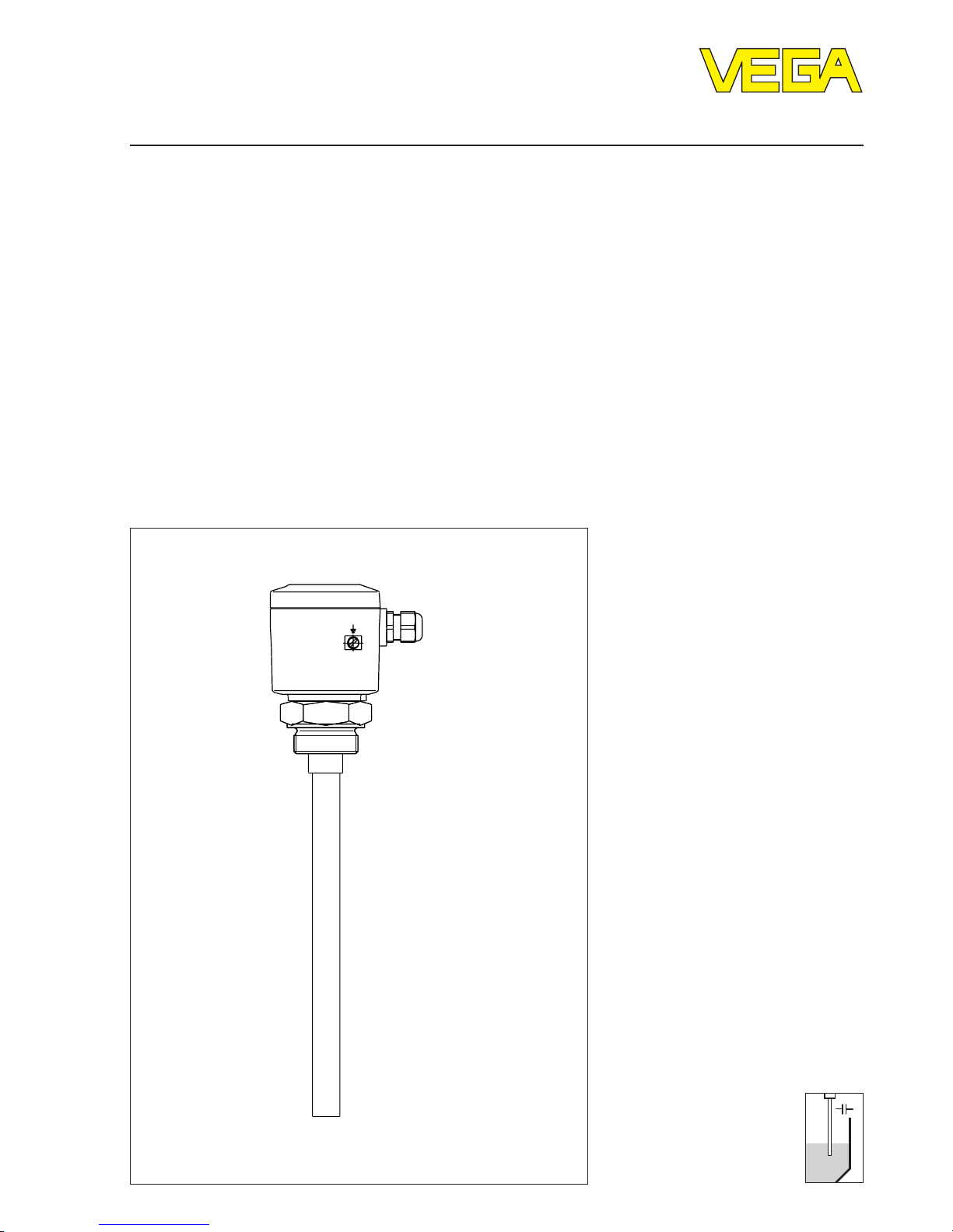
Capacitive electrodes EL
4 … 20 mA - compact
Page 2

2 Capacitive electrodes EL 4 … 20 mA - compact
Safety information
Safety information
The described module must only be installed and
operated as described in this operating
instruction. Please note that other action can
cause damage for which VEGA does not take
responsibility.
Page 3

Capacitive electrodes EL 4 … 20 mA - compact 3
Contents
Safety information ......................................................................... 2
1 Product description
1.1 Function and configuration ................................................... 4
1.2 Types and versions ............................................................... 5
1.3 Technical data ....................................................................... 7
1.4 Approvals ............................................................................ 13
1.5 Dimensions ......................................................................... 14
1.6 Type plate ........................................................................... 16
2 Mounting
2.1 Mounting instructions .......................................................... 17
3 Electrical connection
3.1 Connection instructions ...................................................... 22
3.2 Wiring plan .......................................................................... 22
4 Set-up
4.1 General adjustment ............................................................ 26
4.2 Adjustment - Oscillators
CAP E32 Ex and CAP E32 H Ex ......................................... 27
4.3 Adjustment with VVO ............................................................ 30
4.4 Adjustment with HART®-handheld ..................................... 36
5 Diagnosis
5.1 Simulation ........................................................................... 44
5.2 Maintenance ....................................................................... 44
5.3 Repair ................................................................................. 44
5.4 Failure removal.................................................................... 45
Contents
Page 4

4 Capacitive electrodes EL 4 … 20 mA - compact
Product description
1 Product description
1.1 Function and configuration
Capacitive electrodes series EL detect levels of
virtually any medium unaffected whether
liquids, powders or pastes. This is also valid for
adhesive products.
The electrode measures also the level
capacitance and the ohmic resistance
(admittance processing). Hence also
problematic medium and solids with fluctuating
humidity contents can be detected.
By the use of screening tubes and screen
segments, inactive areas can be provided on
the probe where pollution, condensation or
permanent build-up do not influence the
measuring result.
Measuring principle
Electrode, medium and vessel wall form an
electrical capacitor.
The capacitance of the capacitor is mainly
influenced by three factors:
- distance of the electrode plates (a)
- size of the electrode plates (b)
- kind of dielectricum between the electrodes
(c)
Fig. 1.1 Plate capacitor (schematic
demonstration)
Electrode and vessel wall are the capacitor
plates. The medium is the dielectricum. Due to
the higher dielectric constant figure (DK-value)
of the medium against air, the capacitance of
the capacitor increases with raising covering of
the electrode.
Fig. 1.2 Capacitance change with covered
electrode
a
b
c
The capacitance change is processed by the
oscillator and converted into a level proportional measured value. The measured value is
provided analogue as standardized, floating
4 … 20 mA-current signal, optionally also
digitally with the HART®-communication
protocol.
The sensor can be adjusted via the integral
oscillator. Optionally the adjustment with
HART®-handheld or PC with VVO-adjustment
software is also possible.
With the continuous level measurement the
appropriate level is continuously detected and
converted into a level proportional signal which
is either directly displayed or further processed.
You require a capacitive electrode series EL
with oscillator CAP E32 Ex or CAP E32 H Ex.
The continuous measurement assumes a
constant dielectric constant figure εr , i.e. the
medium should have steady features.
Page 5

Capacitive electrodes EL 4 … 20 mA - compact 5
Product description
*) also Ex 0
1) applied
2) 1.4435
3) 1.4571
4) 1.4401
5) For electrodes certified for Ex-Zone 0,only PTFE and FEP are approved as isolating material
1.2 Types and versions
Type EL EL EL EL EL EL EL EL EL
Version 11*
)
21*
)
24*
)
29 31*
)
33 42*
)
52 53
Continuous •••••••••
Partly-insulated • • •
Fully-insulated • • • • • •
Oscillators
CAP E32 EX •••••••••
CAP E32 H EX •••••••••
Approvals
PTB 98 ATEX 2086 • • • • •
PTB-no. Ex-98.E.2085 • • • • •
Overfill protection
acc. to WHG
1)
••••• •
German Lloyd
1)
•••••••••
Lloyds Register of Ship
1)
•••••••••
American Bureau of Ship
1)
•••••••••
Bureau Veritas
1)
•••••••••
RINA
1)
•••••••••
Mechanical connection
G 1 A • • • • • •
NPT 11/2" •• ••••••
G 11/2 A ••• •••••
Tri-Clamp 11/2“••
Tri-Clamp 2“ • • • • •
Bolting
DN 50 • • •
Flange • • • • ••••
Flange plated •
Screw adapter
PP ••• ••
PTFE • • • •
Electrode material
Steel • • • ••••
StSt •
2)
•
2)
•
2)
•
3)
•
3)
•
4)
•
2)
•
2)
Page 6

6 Capacitive electrodes EL 4 … 20 mA - compact
Type EL EL EL EL EL EL EL EL EL
Version 11*)21*
)
24*
)
29 31*
)
33 42*
)
52 53
Isolation material
5)
PTFE • • • • • •
PP • •
PE/PA 12 •
PFA •
FEP • •
PE •
Concentric tube
Steel • • •
StSt (1.4435) • • •
Screening tube (option)
Steel • • • • • • • •
StSt • • • • • • • •
Temperature
adapter (option)
Steel • • • • •
StSt (1.4435) • • • • •
PA • • • • • • •
Housing material
Plastic • • • • • • • • •
Aluminium • • • • • • • • •
Others
Adapter
6)
•• • •
Overvoltage protect.-option
CB-2-36 (integrated) • • • • • • • • •
Overvoltage arrester
7)
•• ••
Bending of
electrode
8)
••
9)
*) also Ex 0
1) applied
2) 1.4435
3) 1.4571
4) 1.4401
5) For electrodes certified for Ex-Zone 0, PTFE and FEP are only approved as isolation material
6) For combustible liquids in pressurized vessels, e.g. liquid gas, ammonia
7) For high electrostatic discharges, e.g. plastic granules
8) Bending max. 90°
9) EL 21 only with PTFE at 3,2 mm isolation thickness
Product description
Page 7

Capacitive electrodes EL 4 … 20 mA - compact 7
Product description
1.3 Technical data
Housing
Housing material plastic PBT (Polyester) or Aluminium
plastic coated
Protection
- plastic housing IP 66
- Aluminium housing IP 66/67 (meets both protections)
Cable entry 1 piece M20 x 1,5
Terminals for max. 1,5 mm2 cross-section area of conductor
Mechanical connection
Material galvanized steel (St 37), 1.4571 (StSt), Aluminium
Thread G 1
1/
2
A or 1
1/
2
" NPT
Flange flange versions
Electrode
Material EL 11 1.4435 (316 L)
EL 21 steel (St 37)
EL 31 1.4401 (316 L)
EL 24, 42 1.4571 (316 L)
Length
- rod max. 3 m
- cable max. 20 m
Isolation see "Isolation materials"
Max. tensile load (cable)
- EL 31 3 KN
- EL 33, 34, 42, 52, 53 3 KN
Ambient conditions
Ambient temperature on the housing -40°C … +80°C
Medium temperature see "Medium temperature and operating pressure"
Storage and transport temperature -40°C … +80°C
Operating pressure see "Medium temperature and operating pressure"
Oscillator CAP E32 Ex, CAP E32 H Ex
Protection class II
Overvoltage category III
Meas. frequency 300 KHz
Capacitance ranges 0 … 3000 pF
Page 8

8 Capacitive electrodes EL 4 … 20 mA - compact
Oscillators in two-wire technology for capacitive electrodes EL
Type Application Meas. range Freguency Signal cond.instr.
CAP E32 Compact electronics 4 … 20 mA for 0 - 3000 pF 300 KHz not required
Ex continuous level measurement,
according to the principle of
phase selective admittance processing
Parameter adjustment via
keys on the oscillator
CAP E32 H Compact electronics 4 … 20 mA for 0 - 3000 pF 300 KHz not required
Ex continuous level measurement,
according to the principle of
phase selective admittance processing
Parameter adjustment via
keys on the oscillator,
VVO from V. 2.30 or
HART®-handheld
Accessory
Straining spring of 1.4571
- length approx. 185 mm (stressed)
- tensile load approx. 200 N
Weight
Basic weight (e.g. EL 24) approx. 0,8 kg
Rod weight ø 6 mm - 0,23 kg/m
ø 10 mm - 0,62 kg/m
Product description
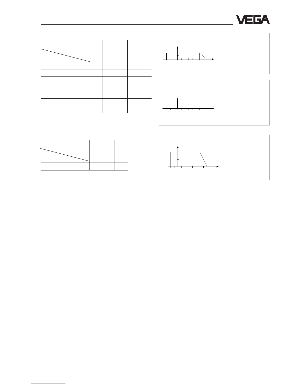
12
200
600
800
18 24 30 36
1000
Load in Ω
Supply
voltage in V
Supply voltage 12 … 36 V DC
for Ex-applications note the stated permissible
electrical connection values in the certificate.
Potential separation min. 500 V AC
Page 9

Capacitive electrodes EL 4 … 20 mA - compact 9
Product description
+
–
0 %
5 %
10 %
15 % vol.
fully insulated
electrode
partly
insulated
electrode
Solid
humidity (%)
Level
measured
value
Fig. 1.3 Humidity change
Oscillator
The oscillator CAP E32 (H) Ex with the patented
processing (phase selective admittance
processing) extends the application range of
capacitive level measurement technology. This
function can be switched on, see 4 Set-up.
In conjunction with a fully insulated rod
electrode, the oscillator compensates even
strong conductive build-up.
Mounted in an individual rod or cable electrode
type EL, this oscillator ensures also the exact
measurement in solids with varying humidity
contents.
The oscillator processes the measuring
currents according to the phase position.
Measuring currents with a defined phase
shifting as they occur with build-up or humidity
changes are filtered out.
Humidity change
A humidty change in solids causes a change of
the dielectric constant figure (εr). In parallel the
ohmic value of the medium changes. Due to the
change also a phase shifting of the measuring
currents is caused.
With a capacitive measurement already lowest
humidity changes cause measuring errors.
Typical products are, e.g. sand, aggregate in
the cement industry, hop or plastic granules
(after drying).
When using the oscillator CAP E32 (H) Ex
humidity changes of 15␣ % vol. do not influence
the accuracy of the measurement. Even
layering of product with different humidity do
not play a role for the measuring accuracy.
When the humidity contents exceeds 15␣ % vol.
1) Actual value level
1)
fully and partly insulated electrodes react
differently (see also “Fig. 1.3 Humidity
change“). Whereby the measured value on fully
insulated electrodes raises with steady level,
the measured value on partly insulated
electrodes drops.
Page 10

10 Capacitive electrodes EL 4 … 20 mA - compact
Product description
0
–10
60 80
40
°C
bar
16
0
–10
100
63
°C
bar
6
5
4
0
–10
100
63
200
°C
bar
25
EL 21, 53:
PE and PE / PA 12
up to 16 bar
Temperature
adapter
2)
EL 42:
up to 16 bar
EL 24:
up to 40 bar
from 100°C
unpressurized
max. 150°C for
30␣ min.
0
–50
100
63
200
°C
bar
25
0
–50
100
63
°C
bar
0
–30
60 80
40
bar
°C
16
3
2
1
EL 21, 53:
PE and PE / PA 12
up to 16 bar
Temperature
adapter
1)
EL 42:
up to 16 bar
EL 24:
up to 40 bar
from 100°C
unpressurized,
max. 150°C for
30␣ min.
1)
Temperature adapter of PA up to 150°C, from 100°C
unpressurized
Medium temperature1) and operating
pressure
1)
The figures in the tables relate to the figures on
this page. The statements on pressure are valid
for screw conenctions G 11/2 A, NPT 11/2“ and R
11/2.
Boltings DN 50 acc. to DIN 11␣ 851 only up to
max. 25 bar. With flange versions you have to
note their nominal pressure.
All electrodes are also suitable for vacuum
(-1␣ bar).
For electrodes certified for Ex-Zone 0, only
PTFE and FEP are approved as isolating
material.
Mechanical connection, 1.4571
Isolation
Electrode type
EL 11 - 1 3 - - EL 21 1-3-3EL 21 (flange) - - 2 - - EL 24 -----2
EL 29 - - 2 - - EL 31 - 1 3 - - EL 33 - - 3 - - EL 42 - - 2 - - EL 52 - - 3 - - EL 53 - - - 1 - -
Mechanical connection, steel (St 37)
Isolation
Electrode type
EL 11 - 4 6 - - EL 21 4-6-6EL 21 (flange) - - 5 - - EL 24 -----5
EL 31 - 4 6 - - EL 33 - - 6 - - EL 42 - - 5 - - EL 52 - - 6 - - EL 53 - - - 4 - -
PE
PP
PTFE
PE/PA 12
PFA
FEP
PE
PP
PTFE
PE/PA 12
PFA
FEP
Page 11
Capacitive electrodes EL 4 … 20 mA - compact 11
8
7
0
–30
100
16
°C
bar
0
–30
60 80
16
°C
bar
Mechanical connection, Aluminium
Isolation
Electrode type
EL 11 - 7 8 - EL 21 7 - 8 - 8
EL 31 - 7 8 - EL 33 - - 8 - EL 42 - - 8 - EL 52 - - 8 - EL 53 - - - 7 -
Mechanical connection, PP, PVC, PTFE,
screwed adapter
Isolation
Electrode type
EL 29 10 10 10
PE
PP
PTFE
PE/PA 12
PFA
1)
For Ex-applications the permissible temperatures and pressures stated in the certificate must be noted.
Additionally note the table on the following page.
2)
Temperature adapter of PA up to 150°C, from 100°C unpressurized
FEP
9
0
–20
60
°C
bar
2
45
1
PP
PTFE
PP: unpressurized up
to 80°C
PTFE: 3 bar,
-20␣ …␣ 100°C
Product description
Page 12

12 Capacitive electrodes EL 4 … 20 mA - compact
Product description
Electronics temperature
The following medium and ambient
temperatures must be kept, so that the limit
temperature on the electronics is not exceeded.
Temperature class T4 (or no Ex)
Without temperature adapter
- medium temperature -40°C … +135°C
- ambient temperature
1)
-40°C … +90°C
Temperature class T3
With temperature adapter
1) Ambient temperature on oscillator
Plastic housing Metal housing
Medium temperature -40°C … 180°C 200°C 150°C 175°C 200°C
Ambient temperature
1)
-40°C … 80°C75°C80°C69°C58°C
Product description
Page 13

Capacitive electrodes EL 4 … 20 mA - compact 13
Product description
1.4 Approvals
Explosion protection
Only certified capacitive electrodes EL** Ex 0
must be used in hazardous areas with
combustible gases, vapours or fog.
Capacitive electrodes EL** Ex 0 are suitable for
the use in hazardous areas of zone 1 and zone
0.
Proof for the explosion protection of these
instruments is the EC-type approval and the
conformity certificate possibly with national
zone 0 - annex issued by the approval
authority. These documents are generally
attached to the instruments.
When the capacitive electrodes are mounted
and operated in hazardous areas, the Exinstallation regulations must be noted.
The information and regulations of the supplied
certificates (EC-type approval, conformity
certificate) of the capacitive electrodes as well
as of the appropriate instrument (signal
conditioning instrument, separator, safety
barrier) must be noted.
• The mounting of Ex-systems must be
generally carried out by skilled staff.
• The capacitive electrodes must be powered
from an intrinsically safe circuit; the
permissible electrical values are stated in the
appropriate certificate.
• Capacitive electrodes with electrostatically
chargeable plastic parts are provided with a
warning label informing about measures
which must be taken to avoid dangers
caused by electrostatic discharges. Note the
contents of the warning label.
• The explosion protection of the instrument
used is only ensured when the limit
temperatures stated in the certificate are not
exceeded.
• In case of danger due to oscillation or
vibration, the appropriate parts of the
capacitive electrodes must be protected.
• After shortening of the electrode cable it
must be noted that the weight is sufficiently
secured by means of pins.
Overfill protection acc. to WHG
The information and regulations of the supplied
type approvals must be noted when a
capacitive electrode is used as overfill
protection for vessels storing water
endangering liquids. The general type approval
must be available on site.
Electrodes must be only used in such liquids
against which the materials of the wetted parts
of the capacitive electrodes are sufficiently
chemically resistant.
Ship approvals
For the use on ships, type approval certificates
are available of several ship classification
authorities (GL, LRS, ABS, BV, RINA).
CE-approval
The capacitive electrodes type EL meet the
protective regulations of EMVG (89/336/EWG)
and NSR (72/23/EWG). The conformity has
been judged acc. to the following standards:
EMVG Emission EN 50 081 - 1
Susceptibility EN 50 082 - 2
NSR EN 61 010 - 1
Zone 2
According to DIN VDE 0165, instruments can
be used in hazardous areas of zone 2 without
approval; they must meet the requirements in
section 6.3 of this VDE. The compliance of the
instruments with these requirements is
confirmed by Messrs. VEGA in a manufacturer
declaration.
Page 14
14 Capacitive electrodes EL 4 … 20 mA - compact
Product description
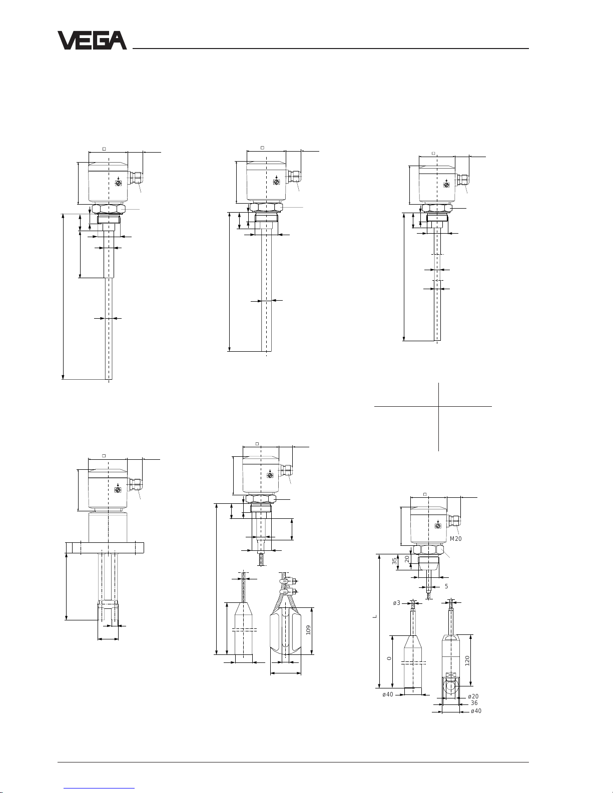
1.5 Dimensions
Dimensions of the capacitive electrodes type EL … Ex 0
Type EL 11
(partly insulated)
(Ex 0)
SW 60
M20x1,5
90
85
32,5
ø20
L1
ø15
35
L
20
G 11/2 A
L (min. 100 mm, max. 4000 mm)
Type EL 21 (fully insulated)
(Ex 0)
SW 60
35
A
L
20
M20x1,5
90
85
32,5
G 11/2 A
L (min. 100 mm, max. 4000 mm)
Isolation length L1:
PP: 100 mm
PTFE: 50 mm
StEx: max. 100 mm
Type EL 24 (fully insulated,
for adhesive products)
(Ex 0)
20
35
ø12
ø14
L
M20x1,5
90
85
32,5
SW 60
G 11/2 A
L (min. 120 mm, max. 4000 mm)
Type EL 29
(fully insulated)
25
ø14
48
L
M20x1,5
90
85
32,5
L (min. 120, max. 3000 mm)
Type EL 31 (partly insulated)
(Ex 0)
L (min. 400 mm, max. 25000 mm)
Isolation length L1:
PP: 100 mm
PTFE: 50 mm
StEx: max. 100 mm
,
109
200
35
L1
L
ø40
71
16
ø8
ø20
20
M20x1,5
90
85
32,5
Isolation A
outer-ø
PE 2,0 mm 20 mm
PTFE 2,0 mm 20 mm
PTFE 3,2 mm 16 mm
PFA 2,0 mm 20 mm
,,
,,
,,
ø3
,,
,,
,,
ø5
35
ø3
ø40
200
L
120
ø20
36
ø40
20
M20x1,5
90
85
32,5
Type EL 42 (fully insulated)
(Ex 0)
L (min. 400 mm, max. 25000 mm)
SW 60
SW 60
Page 15

Capacitive electrodes EL 4 … 20 mA - compact 15
Product description
Housing
Housing of plastic / Aluminium
M20x1,5
90
32,5
85
Temperature adapter
Adapter
for combustible liquids in pressurized
vessels, e.g. liquid gas, ammonia
Concentric tube
Screening tube
ø38
L
SW 60
of galvanized steel
or 1.4571
SW 60
ø45
54
ø60
ø60
70
Temperature adapter
10
ø38
L
of St or 1.4571 with
closing cone of PP or
PTFE
of St or 1.4571
of PA, for
temperatures up
to 150°C, from
100°C only
unpressurized
200
90
ø66
ø66
G 11/2 A
20
44
Screwed adapter of
PP or PTFE
Closing cone
Type EL 52 (fully insulated)
M20x1,5
90
85 32,5
125
35
L
ø40
ø40
ø20
36
ø15,5
ø8
200
20
M20x1,5
90
85 32,5
120
L
ø40
ø40
ø20
36
ø11
ø6
200
35
20
Type EL 53 (fully insulated)
L (min. 400 mm, max. 25000 mm)L (min. 400 mm, max. 25000 mm)
Page 16

16 Capacitive electrodes EL 4 … 20 mA - compact
ser. no. 10612892
Product description
1.6 Type plate
Before mounting and electrical connection
please check if you use the suitable instrument.
Therefore note the type plate which is located
as follows:
1 Master data of the order no.
2 Ex-certification number
Explosion protection version - note the
information and regulations of the certificate
3 Data of the electronics / Approvals
4 No. of the order confirmation /Pos.-no.
5 Number of the electrode type
6 Serial number
7 Test mark when used as part of an overfill
protection for vessels storing water
endangering liquids - note the information
and regulations in the general type approval
8 Manufacturing year
9 Number of the test authority
Type plate
The type plate contains important data required
for mounting and connection. The configuration
and components of the type plate are hence
explained in the following example.
Configuration of the type plate (example)
Order code
Detailled information on the order you will find
in the “Product Information Capacitive“ or in the
“VEGA-Pricelist“.
6
VEGA® EL 11
type EL11EXO.XGBVSTXXVKXX
see PTB Nr. EX-98.E.2085 EEx ia IIC T6 0032
PTB 98 ATEX 2086 II 1/2G EEx ia IIC T6
techn. data see document. / certificates 1998
protection: IP 66/67 Insp.
length: 400mm VVO: 02
Ord. no. 123456/000
3
1
4
2
®
D-77757 Schiltach
5
Z-65.13.XXX
7
9
8
Page 17

Capacitive electrodes EL 4 … 20 mA - compact 17
Mounting
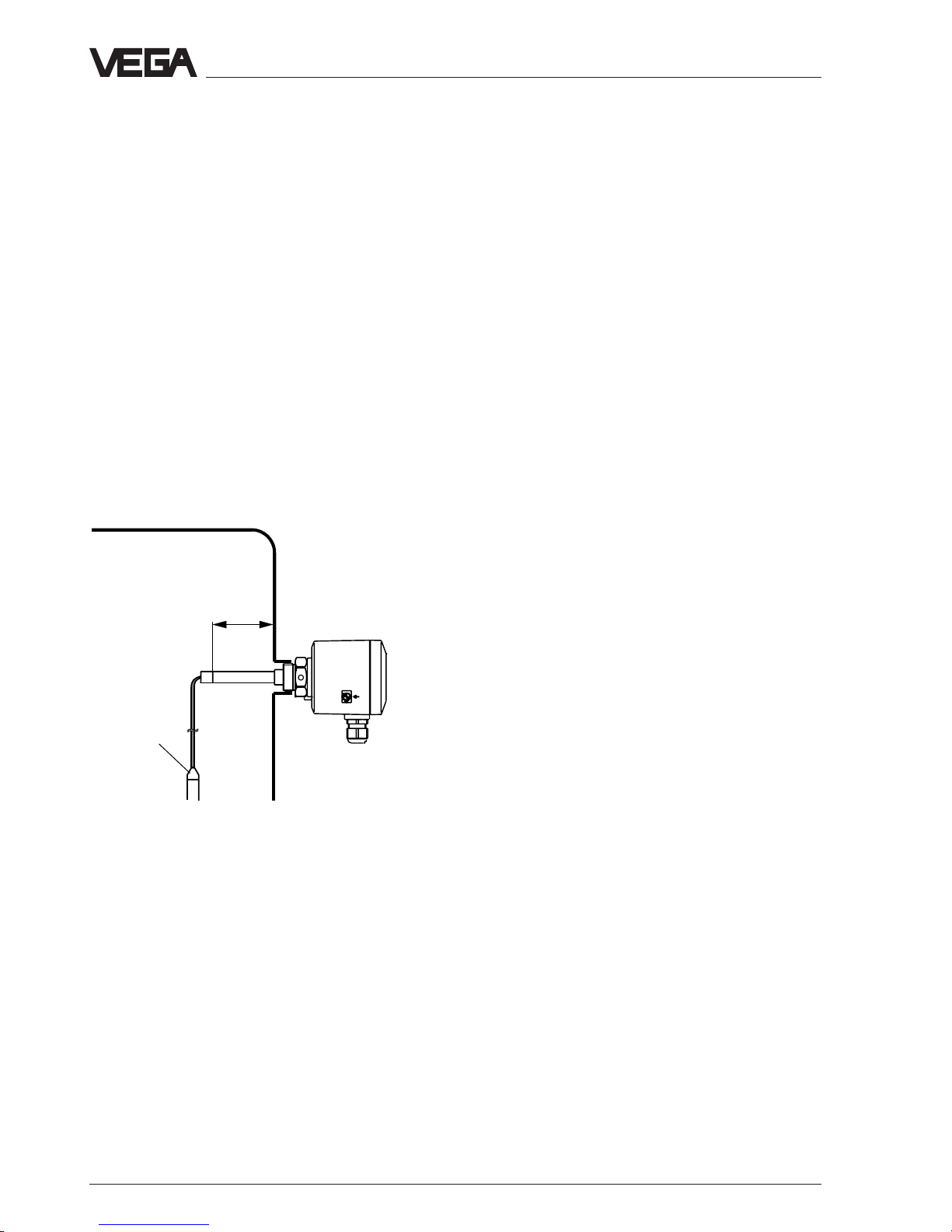
Fig. 2.1 Lateral load
2 Mounting
2.1 Mounting instructions
General
Different mediums and requirements to the
measurement require various installations.
Hence the following instructions should be
noted.
Lateral load
Note that the electrode is not subjected to
strong lateral forces. Mount the electrode in a
position in the vessel where no interfering
influences such as e.g. stirrers, filling opening
etc. occur. This is mainly valid for very long rod
and cable electrodes.
Extraction forces
In case of strong extraction forces e.g. during
filling or settling of solids, high tensile loads can
be caused.
In these cases use for short measuring
distances a rod electrode, as a rod is generally
more stable. If due to the length or the
mounting position a cable electrode should be
necessary, the electrode should not be
strained, but only equipped with a gravity
weight as then the cable can more easily follow
the product movements. Note that the electrode
cable does not touch the vessel wall.
Pressure
In case of gauge or low pressure in the vessel,
the mounting boss must be sealed on the
thread. Use the attached seal ring. Check if the
seal ring is resistant against the medium.
Isolating measures such as e.g. the covering of
the thread with Teflon tape can interrupt the
electrical connection in case of metal vessels.
Hence earth the electrode on the vessel.
Page 18

18 Capacitive electrodes EL 4 … 20 mA - compact
Fig. 2.3 Humidity
Mounting
Fig. 2.2 Shortening of the electrode
,,,,,,
,
,,,,,,
,
,,,,,,
,
,,,,,,
,
,,,,,,
,
,,,,,,
,
,,,,,,
,
,,,,,,
,
,,,,,,
,
,,,,,,
,
,,,,,,
,
,,,,,,
,
,,,,,,
,
,,,,,,
,
,,,,,,
,
,,,,,,
,
,,,,,,
,
,,,,,,
,
,,,,,,
,
,,,,,,
,
,,,,,,
,
,,,,,,
,
,,,,,,
,
,,,,,,
,
,,,,,,
,
,,,,,,
,
,,,,,,
,
,,,,,,
,
,,,,,,
,
,,,,,,
,
,,,,,,
,
,,,,,,
,
,,,,,,
,
,,,,,,
,
,,,,,,
,
,,,,,,
,
,,,,,,
,
,,,,,,
,
,,,,,,
,
,,,,,,
,
,,,,,,
,
,,,,,,
,
,,,,,,
,
,,,,,,
,
,,,,,,
,
,,,,,,
,
,,,,,,
,
,,,,,,
,
,,,,,,
,
,,,,,,
,
,,,,,,
,
,,,,,,
,
,,,,,,
,
,,,,,,
,
,,,,,,
,
,,,,,,
,
,,,,,,
,
,,,,,,
,
,,,,,,
,
,,,,,,
,
,,,,,,
,
,,,,,,
,
,,,,,,
,
,,,,,,
,
,,,,,,
,
,,,,,,
,
Shortening of the electrode
The dimensions of fully insulated electrodes are
fixed and must hence not be modified. Each
modification will destroy the instrument.
Partly insulated cable or rod electrodes can be
shortened afterwards.
The electrode basic capacitance is automatically compensated during adjustment. It is
hence possible to shorten the electrodes
individually.
Cable electrode EL␣ 31 can also be shortened
afterwards (see fig. 2.2). Loosen the two pins
on the gravity weight (hexagon) and remove the
two pins. Pull the cable out of the gravity
weight.
To avoid splicing of the steel cable (EL␣ 31)
during cutting, you have to tin the cable around
the cutting position with a copper bit or strongly
tighten the cable with a wire. Shorten the
electrode cable with a metal cutting saw or a
cutting-off wheel by the the requested length.
Carry out the adjustment. The instruction is
under “4.1 Adjustment“.
Filling opening
Install the electrode such that it does not
protrude directly into a strong filling stream.
Should such an installation place be necessary,
mount a suitable sheet above or in front of the
electrode e.g. L␣ 80␣ x␣ 8 DIN 1028, etc.
Humidity from outside
To avoid humidity ingress, loop the connection
line to the electrode housing on vertically
installed electrodes directly behind the cable
entry to the bottom so that rain and
condensation water can drain off.
This is mainly valid for mounting outside, in
areas where humidity must be expected (e.g.
by cleaning processes) or on cooled or heated
vessels (see fig. 2.3).
Cable entries
When mounting outside, on cooled vessels or in
humid areas where cleaning is made e.g. with
steam or high pressure, the seal of the cable
entry is very important.
Use cable with a round cross-section area of
conductor and tighten the cable entry. The
cable entry is suitable for cable diameters of
5␣ mm to 9␣ mm.
Metal vessels
Page 19

Capacitive electrodes EL 4 … 20 mA - compact 19
Mounting
Note that the mechanical connection of the
electrode is electrically conductive connected
with the vessel to ensure sufficient earth.
Use conductive seals such as e.g. copper, lead
etc. Isolating measures such as covering the
thread with Teflon tape can interrupt the
necessary electrical connection. In this case
use the earth terminal on the housing to
connect the electrode to the vessel wall.
Non-conductive vessels
In non-conductive vessels, e.g. plastic tanks,
the second pole of the capacitor must be
provided separately, e.g. by a concentric tube
or the use of a double rod electrode.
When using a standard electrode, a suitable
earth plate is necessary. Hence provide a
possibly large earth plate, e.g. wire braiding
laminated into the vessel wall or metal foil which
is glued to the vessel. Connect the earth plate
with the earth terminal on the housing.
Rod electrode
Mount the rod electrode such that the electrode
protrudes into the vessel. When mounting in a
tube or a socket, build-up can be caused which
can influence the measurement. This is particularly the case with viscous or adhesive
products.
Cable electrodes in solids
Dependent on the kind of solid and position or
kind of filling, the cable electrode can “float“
despite of the gravity weight. The electrode
(cable) is pushed by the solid to the vessel wall
or to the top and wrong measured values are
caused. This should be avoided with
continuous level measurement.
In this case use a fixing weight or a fixing
insulator to fasten the electrode (fig. 2.4).
When fastening the cable electrode avoid high
tensile strenghts. An appropriate fixing spring
avoiding overloading of the cable is listed in our
pricelist as accessory.
Lateral installation
Fig. 2.4 Cable electrode in solids
Page 20
20 Capacitive electrodes EL 4 … 20 mA - compact
L
Fixing weight
Mounting
With electrodes, delivering continuous
measured values, the electrode must only be
installed vertically. Should the installation from
top not be possible, the electrodes can also be
mounted laterally (fig. 2.5)
Under the accessory in our pricelist you find a
screening tube and a closing cone or a bent
rod electrode by which the electrode can be
also mounted laterally. Choose the length (L) of
the screening tube such that no product
bridges can be caused between cable and
vessel wall and that the electrode cable cannot
touch the vessel wall due to product
movements. Use a fixing weight or a fixing
insulator.
Material cone
Fig. 2.5 Continuous electrodes
Page 21
Capacitive electrodes EL 4 … 20 mA - compact 21
Mounting
Filling
Emptying
d
d
d
10
d
10
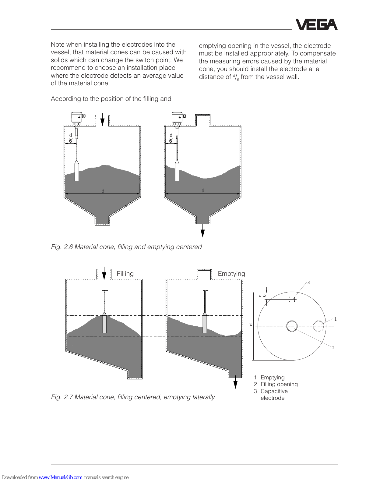
Fig. 2.6 Material cone, filling and emptying centered
d
3
1
2
d
6
Filling Emptying
1 Emptying
2 Filling opening
3 Capacitive
electrode
Fig. 2.7 Material cone, filling centered, emptying laterally
Note when installing the electrodes into the
vessel, that material cones can be caused with
solids which can change the switch point. We
recommend to choose an installation place
where the electrode detects an average value
of the material cone.
According to the position of the filling and
emptying opening in the vessel, the electrode
must be installed appropriately. To compensate
the measuring errors caused by the material
cone, you should install the electrode at a
distance of d/6 from the vessel wall.
6 6
Page 22
22 Capacitive electrodes EL 4 … 20 mA - compact
Note
The oscillator is independent of the electrode
and can be exchanged locally.
Electrical connection
3 Electrical connection
3.1 Connection instructions
Note
Switch off the power supply before starting
connection work.
Connect supply voltage according to the
following connection diagrams.
Note
If strong electromagnetic interferences have to
be expected, we recommend to use screened
cable. The screening of the cable should only
be earthed at one sensor end (electrode).
Generally connect the electrode with vessel
ground (PA). For this purpose there is a terminal
laterally on the housing. This connection is
additionally for the mass reference potential as
well as to drain off electrostatic charges.
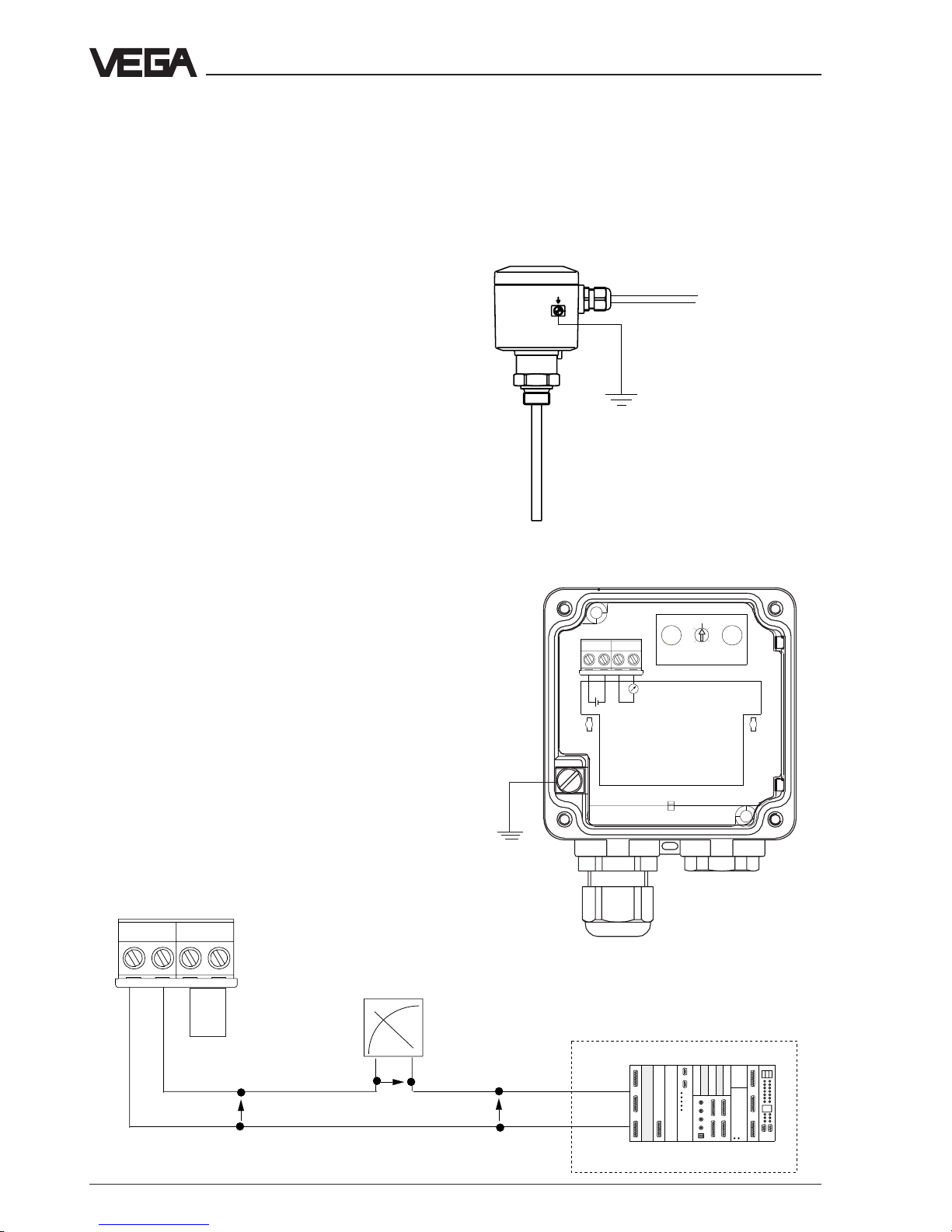
3.2 Wiring plan
+
–
4 … 20 mA
Terminals
sensor
analogue / digital
indicating instrument
U
K
U
H
U
A
4 … 20 mA
U = 12 … 36 V
DCS
4
3
2
1
+ - + -
Ri < 250
+
–
with bridge:
12 …36 V
without
bridge:
13 … 36 V
4
3
2
1
+
-
8
0
2
6
4
+ - + -
mA
U = 12 … 36 V
Page 23

Capacitive electrodes EL 4 … 20 mA - compact 23
Electrical connection
Skilled staff
Instruments operated in Ex-areas must only be
mounted by skilled staff. They must note the
mounting regulations and the supplied EC-type
approvals and conformity certificates.
When capacitive electrodes are mounted on
vessels which must be protected according to
TRbF 100 no. 8, para.1 against inflammation
due to lightning, they have to be equipped with
the external overvoltage arrester type
B 62-36 G or the internal overvoltage protection
unit type CB 2-36.
Page 24

24 Capacitive electrodes EL 4 … 20 mA - compact
Electrical connection
A
B
2
1
E2
E1
A2
A1
2
1
A2
A1
E2
E1
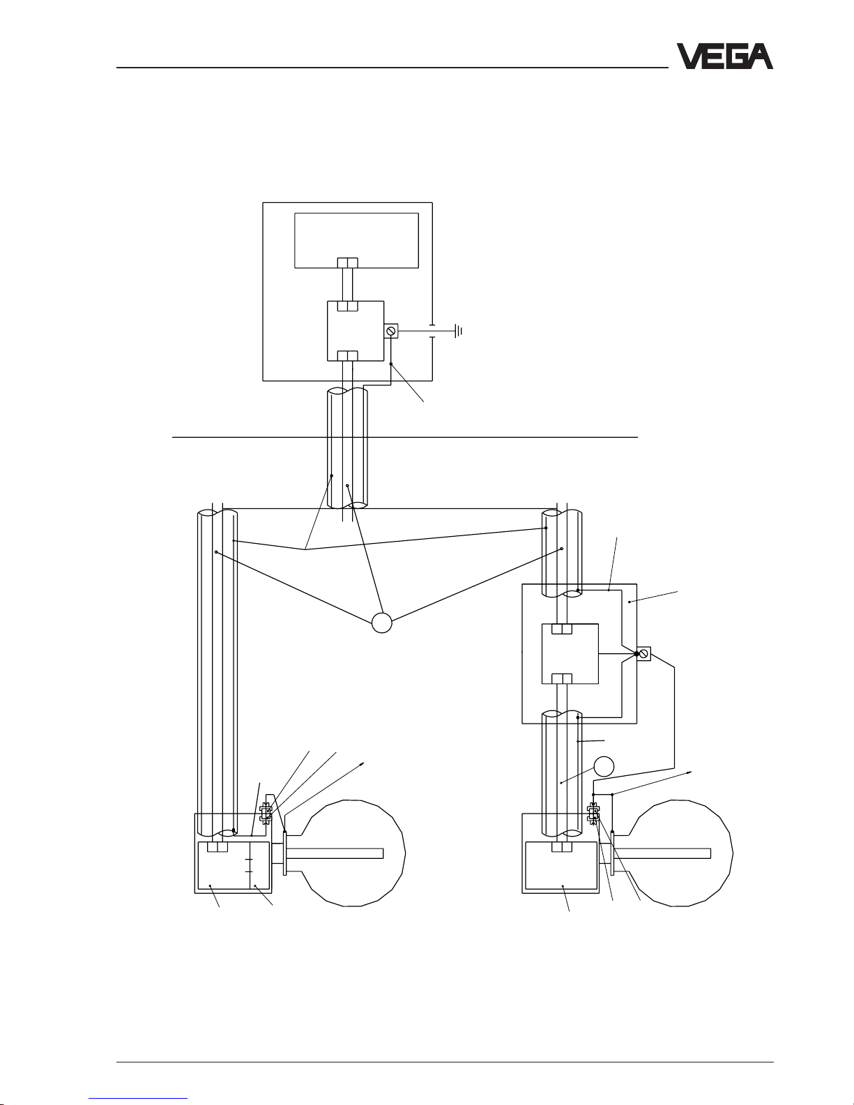
Vessel with cathodic corrosion protection
(Ex)-area Zone 1
Not (Ex)-area
overvoltage
protection unit
mounted on
oscillator
Oscillator
b)Capacitive electrodes with external overvoltage
protection unit
Screen
Cathodic tank protection
2 … 24 V (object voltage)
CB
2-36
CAP
E32(H)EX
External earth terminal
Internal earth terminal
Vessel
Zone 0
Li, Ci of the oscillator with
overvoltage protection unit
Li = 0,27 mH
Ci = 8,5 nF
Control room
either: Overvoltage
protection insert
Signal
cond.
instr.orsafety
barrier
Type B62-36G
Li=0,15 mH
Ci=2,5 nF
Overvoltage protection insert
Overvoltage protection
instrument in metal
housing or plastic
housing. The metal
housing must be
mounted earth free
External earth terminal
Internal earth terminal
Cathodic tank protection
2 … 24 V (object voltage)
Isolated line
min. 4 mm
2
Vessel
Zone 0
Oscillator
Li=0,12 mH
Ci=6 nF
Screen
CAP
E32
(H)Ex
Type
B62-36G
Li=0,15 mH
Ci=2,5 nF
Between control room and overvoltage protection
system a suitable cable must be used, if
necessary with metal cover or screen. Metal
cover or screen - if necessary - must be only
connected to the overvoltage protection system
on the electrode side. The cable must have an
outer isolation. Test voltage of the cable A: ≥ 500
V AC
Between overvoltage protection system and
capacitive electrode a suitable cable with metal
cover, screen or a suitable cable with metal
protection tube must be used (metal cover or
protection tube must not be earthed).
Test voltage of the cable B: ≥ 1500 V AC
a) Capacitive electrodes with integral overvoltage
protection unit type CB 2-36
A
B
Page 25
Capacitive electrodes EL 4 … 20 mA - compact 25
Electrical connection
Vessel without cathodic corrosion protection
A
B
A2
A1
E2
E1
2
1
2
1
E2
E1
A2
A1
Overvoltage
protection unit
mounted on
oscillator
Oscillator
CB
2-36
CAP
E32(H)EX
Vessel
Zone 0
Oscillator
Li=0,12 mH
Ci=6 nF
External earth terminal
Internal earth terminal
Vessel
Zone 0
CAP
E32
(H)Ex
External earth terminal
Internal earth terminal
Li, Ci of the oscillator with
overvoltage protection unit
Li = 0,27 mH
Ci = 8,5 nF
(Ex)-area Zone 1
Not (Ex)-area
Signal
cond.
instr.orsafety
barrier
Control room
either:
Overvoltage
protection unit
Type B62-36G
Li=0,15 mH
Ci=2,5 nF
Overvoltage protection unit
Type
B62-36G
Li=0,15 mH
Ci=2,5 nF
Isolated line
min. 4 mm
2
*
**
Screen
Between control room and overvoltage
protection system a suitable cable, if
necessary a metal cover or screen, must be
used. Metal cover or screen - if necessary -
must only be connected to earth or PA on
one line end.
Test voltage of the cable A: ≥ 500 V AC
Between overvoltage protection system
and capacitive electrode a suitable cable
with metal cover, screen or a suitable cable
with metal protection tube must be used
(metal cover or protection tube must be
connected with the potential equalisation).
Test voltage of the cable B: ≥ 1500 V AC
A
B
Overvoltage arrester type
B62-36 G in metal or plastic
housing
**
to potential
equalization line
Screen
to potential
equalization line
b)Capacitive electrodes with external
overvoltage protection unit
a)Capacitive electrodes with integral
overvoltage protection unit type CB 2-36
*
* either
screen only connected on one
line end to earth or PA
** either
screen only connected on one
line end with earth or PA
Page 26

26 Capacitive electrodes EL 4 … 20 mA - compact
Set-up
4 Set-up
4.1 General adjustment
The figures in brackets relate to the pictures
under chapter “3 Electrical connection“. With
the set-up the electrode must be adjusted with
the original medium.
In certain cases also a dry adjustment can be
carried out.
The electrode can be adjusted in three different
ways:
• with integrated oscillator
• with operating software VEGA Visual
Operating (VVO from V. 2.30)
• with HART®-handheld
CAP E 32 Ex
Adjustment - directly on the oscillator.
CAP E 32 H Ex
Adjustment - directly on the oscillator
- via PC with adjustment
program VVO
1)
- via HART®- handheld
Oscillator
The capacitive electrodes EL can be directly
adjusted on the oscillators CAP E32 Ex and
CAP E32 H Ex.
All sensor basic functions can be carried out
with the two keys and the rotating switch.
PC with adjustment program VVO
1)
With the adjustment program VVO V. 2.30
(VEGA Visual Operating) on the PC you can
adjust the capacitive electrode in conjunction
with oscillator CAP E 32 H Ex very comfortably.
Beside the sensor basic functions, also additional functions are available.
You require an interface adapter
VEGACONNECT 2, which you can connect to
any individual position of the signal line or
directly on the sensor.
System requirements:
- IBM-compatible PC with a free standard
interface. We recommend a PC with Pentiumprocessor with a clock frequency of
100 MHz.
- Memory: 16 MB
- Software requirements: Windows 95
HART®-handheld
The capacitive electrodes EL with oscillator
CAP E32 H Ex are suitable for HART®-protocols
and can be adjusted with a HART®-handheld.
All relevant sensor functions are possible with
the HART®-standard menus. A manufacturer
specific DDD (Data-Device-Description) is not
required.
1) When you want to adjust a sensor with the PC, you
have to connect the PC-lines on the signal line
outside the Ex-zone.
The intrinsic safety must be ensured with the
connection. Use a suitable interface converter e.g.
VEGACONNECT 2
Page 27

Capacitive electrodes EL 4 … 20 mA - compact 27
4
321
+
-
8
0
2
6
4
4.2 Adjustment Oscillators
CAP E32 Ex and CAP E32 H Ex
Set-up
Functional description
0 Operate
Basic position
The instrument should be in this position during
measurement. In mode Operate the actual
measured value is transmitted. The plus and
minus keys do not function.
1 Min. adjustment
This function is used to carry out the min.
adjustment. Empty the vessel to min. level
(0 % - level).
Push the plus and minus key together to set the
current value for the actual level to 4 mA.
When you want to coordinate a certain current
value to a known level, you can modify the
current with the plus and minus keys. Every
time you push the key, the current value will be
changed in 10 µA-steps. When you keep the
key pushed, the value modifies with increasing
speed.
Example: When you know that your vessel is
filled to 10 %, then you can enter under min.
adjustment a value of 5,6 mA.
20 mA - 4 mA = 16 mA
16 mA * 10% = 1,6 mA
1,6 mA + 4 mA = 5,6 mA
It is recommended to connect an amperemeter,
see 3.2 Electrical connection. You can monitor
the current value during modification. When you
keep the key pushed, the value changes
automatically and with increasing speed. The
difference between min. and max. adjustment
should be at least 20% or 3,2 mA.
(+/-) set 4 mA
(+) increase current
(-) lower current
2 Max. adjustment
You use this function to carry out the max.
adjustment. Fill the vessel to max. level (100 %
level). Push the plus and minus key together.
You can set the current value for the actual level
to 20 mA.
When you want to coordinate a certain current
Rotating switch (2)
With the rotating switch (10 steps) you choose
the appropriate mode.
As soon as you continue to turn the rotating
switch, the modified value is taken over.
0 Operate
1 Min. adjustment
2 Max. adjustment
3 Integration time
4 Reverse characteristics
5 Linearisation
6 Sensor optimization
7 Simulation current
8 Reset
9 Offset correction
Plus and minus keys (3 and 1)
With the keys + and - you can modify the
values of the parameters and choose out of
several possibilities.
When you push both keys together, the value of
the appropriately chosen function is reset to
factory setting
(except min./max. adjustment)
4
3
2
1
+ - + -
mA
U = 12 … 36 V
1
2
3
1 Minus switch
2 Rotating switch
3 Plus key
Page 28

28 Capacitive electrodes EL 4 … 20 mA - compact
Set-up
value to a known level, you can modify the
current with the plus and minus keys. Each time
you push the key, the current value changes in
10 µA-steps.
When you keep the key pushed, the value
changes with raising speed.
Example: When you know that your vessel is
filled to 90 % and should be filled to 100 %,
then you can enter under the min. adjustment a
value of 18,4 mA.
20 mA - 4 mA = 16 mA
16 mA * 90% = 14,4 mA
14,4 mA + 4 mA = 18,4 mA
It is recommended to connect an amperemeter,
see 3.2 Electrical connection. You can monitor
the current value during modification. When you
keep the key pushed, the value changes
automatically and with increasing speed. The
difference between min. and max. adjustment
should be at least 20% or 3,2 mA.
(+/-) set 20 mA
(+) increase current
(-) reduce current
3 Integration time
When you want to adjust the integration time
(damping), set the rotating switch to position 3.
With the plus and minus keys you can double
or halve the value of the integration time step
by step. As a standard feature an integration
time of 0,5 seconds is adjusted. Count how
often you have pushed the key, so that you can
adjust the time correctly. If you are not sure, set
the integration time to the preadjusted value of
0,5 s by pushing both keys together. Then
repeat the adjustment.
After the adjusted integration time 63 % of the
measured value change are available at the
output.
The following integration times can be chosen
on the oscillator: 0,5; 1; 2; 4; 8; 16; 32; 64;
128; 256 (s)
(+/-) 0,5 s
(+) increase time
(-) reduce time
Example: To adjust an integration time of 8
seconds, you have to push the key “+“ 4 times.
4 Reverse characteristics
With this function you can reverse the
characteristics of the current output. The
reverse characteristics is visible on the
amperemeter.
(+/-) 4 ... 20 mA
(-) 4 ... 20 mA
(+) 20 ... 4 mA
5 Linearisation
With this function you can activate the saved
linearisation curve. As a standard feature the
curve for cylindrical tank is saved.
On CAP E 32 H you can enter other
linearisation curves via VVO. In this case there
is no preadjustment necessary on the oscillator.
(+/-) linearisation off
(+) linearisation on
(-) linearisation off
6 Sensor optimization
Mode 1 = Phase angle 90°
Mode 1 is a pure capacitance measurement,
the ohmic resistance is not considered in the
measuring result.
Application:
- standard adjustment
- non-conductive liquids up to approx. 50 µS
- compensation of the resistance changes in
liquids
- generally on partly insulated electrodes in
liquids
- non-conductive solids without humidity
contents
- with bad product earth
- with electrodes in conjunction with a
concentric tube
- in non-conductive vessels with ground plate
provided from outside
Mode 2 = Phase angle 45°
The capacitance and the ohmic resistance are
Page 29

Capacitive electrodes EL 4 … 20 mA - compact 29
Set-up
measured separately, the capacitance value is
corrected by the calculation of the ohmic
resistance so that measuring errors due to
build-up or change in the product humidity are
compensated.
Application:
- high conductivity products
- adhesive, conductive products
- solids with fluctuating humidity contents
For the use in conductive, adhesive liquids, the
suitable electrode type EL 24 should be
applied.
(+/-) Mode 1 (90°)
(+) Mode 1 (90°)
(-) Mode 2 (45°)
7 Simulation current
With this function you can simulate the level. As
soon as you set the rotating switch to position 7,
the simulation is active. The actual current value
of the actual level is taken over for simulation.
With the plus and minus keys you can modify
the current value in a range of 3,8 mA to 22 mA.
Every time you push the key, the current value
changes in 10 µA-steps.
When you keep the key pushed, the value
modifies automatically and with increasing
speed.
(+) increase current
(-) reduce current
8 Reset
All adjusted values are reset to factory setting.
Note that also the adjustment is deleted. Tag
number, measurement loop designation etc.
from the HART® or VVO-adjustment however
remain unchanged.
(+/-) Factory setting
Factory setting
0 Operate ---
1 Min. adjustment 4 mA at 0 pF
2 Max. adjustment 20 mA at 3000 pF
3 Integration time 0,5 s
4 Reverse characteristics 4 ... 20 mA
5 Linearisation off
6 Sensor optimization mode 1 (90°)
7 Simulation current off
8 Reset --9 Offset correction already saved values
remain
9 Offset correction
This function is required when an adjustment
should be carried out in m. This is only possible
with an oscillator CAP E 32 H Ex. With this
function the initial capacitance in the
electronics is saved. Requirement is that the
electrode is mounted in the vessel and
completely uncovered.
On electrodes with concentric tube this function
is already carried out as factory setting as the
vessel does not influence the measurement.
The offeset correction must only be repeated
when exchanging the oscillator.
(+/–) Initial capacitance is saved
Page 30

30 Capacitive electrodes EL 4 … 20 mA - compact
4.3 Adjustment with VVO
When an oscillator CAP E 32 H Ex is mounted,
the electrode can be also adjusted via a PC
with adjustment software VVO (from version
2.30).
VVO determines automatically the kind of the
connected sensor and shows a little later to
which sensor the connection exists.
When you get no sensor connection, check the
following:
- The supply voltage must be at least 20 V.
- When VEGACONNECT 2 is directly
connected to the sensor line, the load resistor
must be 250 ... 350 Ohm.
- You have to use a VEGACONNECT 2. Older
versions of VEGACONNECT are not
compatible.
The following adjustment steps are described in
their sequence and should be carried out in this
sequence with the initial set-up.
Further information are stated in the operating
instruction of the adjustment program VEGA
Visual Operating (VVO).
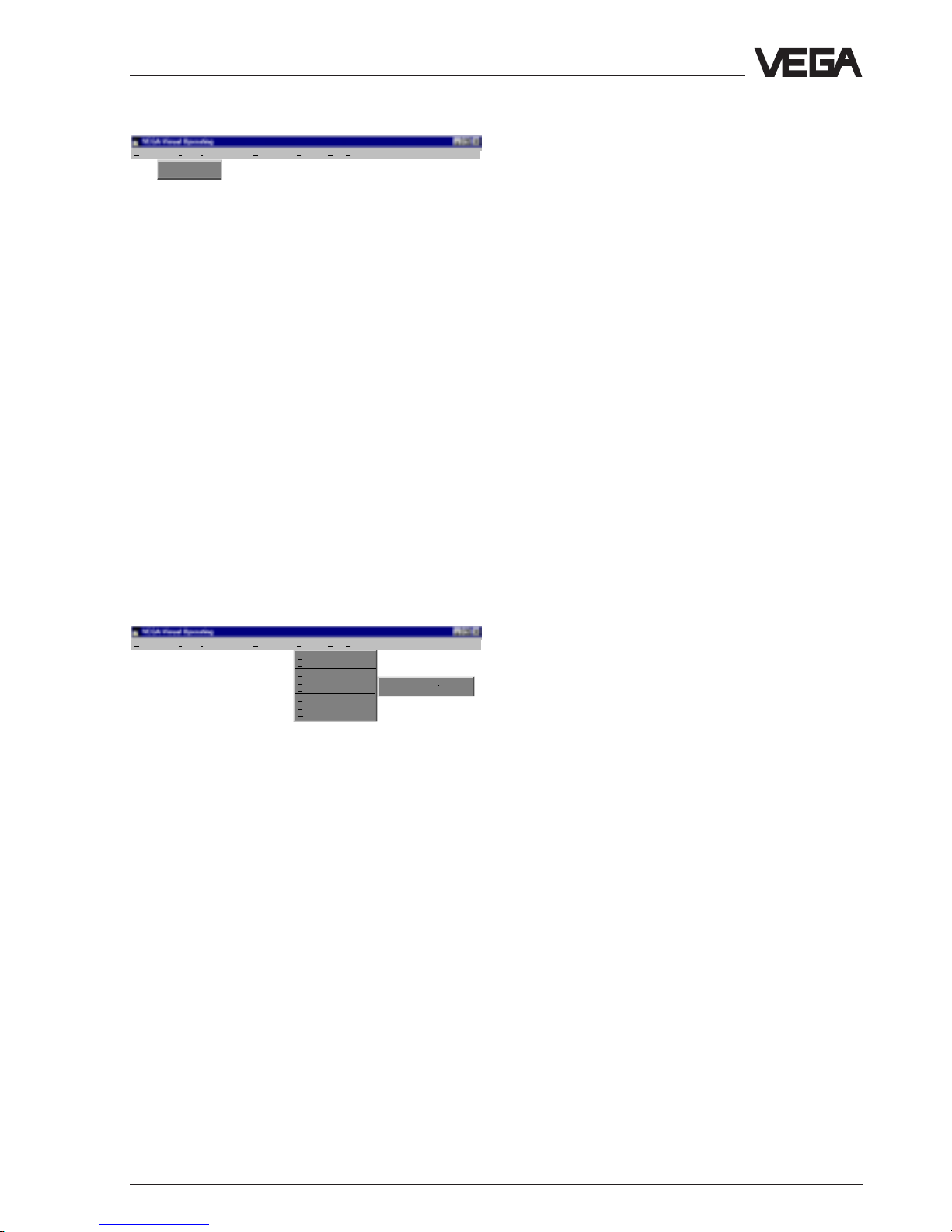
Configuration
Display Diagnostics Instrument data Configuration Services Quit Help
Measuring
system
Measurement loop >
Program >
Language
User access
Communication
Under the menu point Configuration you can
choose the following functions:
• Measuring system
• Measurement loop
• Program
The electrode is preadjusted by VEGA. The
measuring system must only be re-configured
when the oscillator is exchanged.
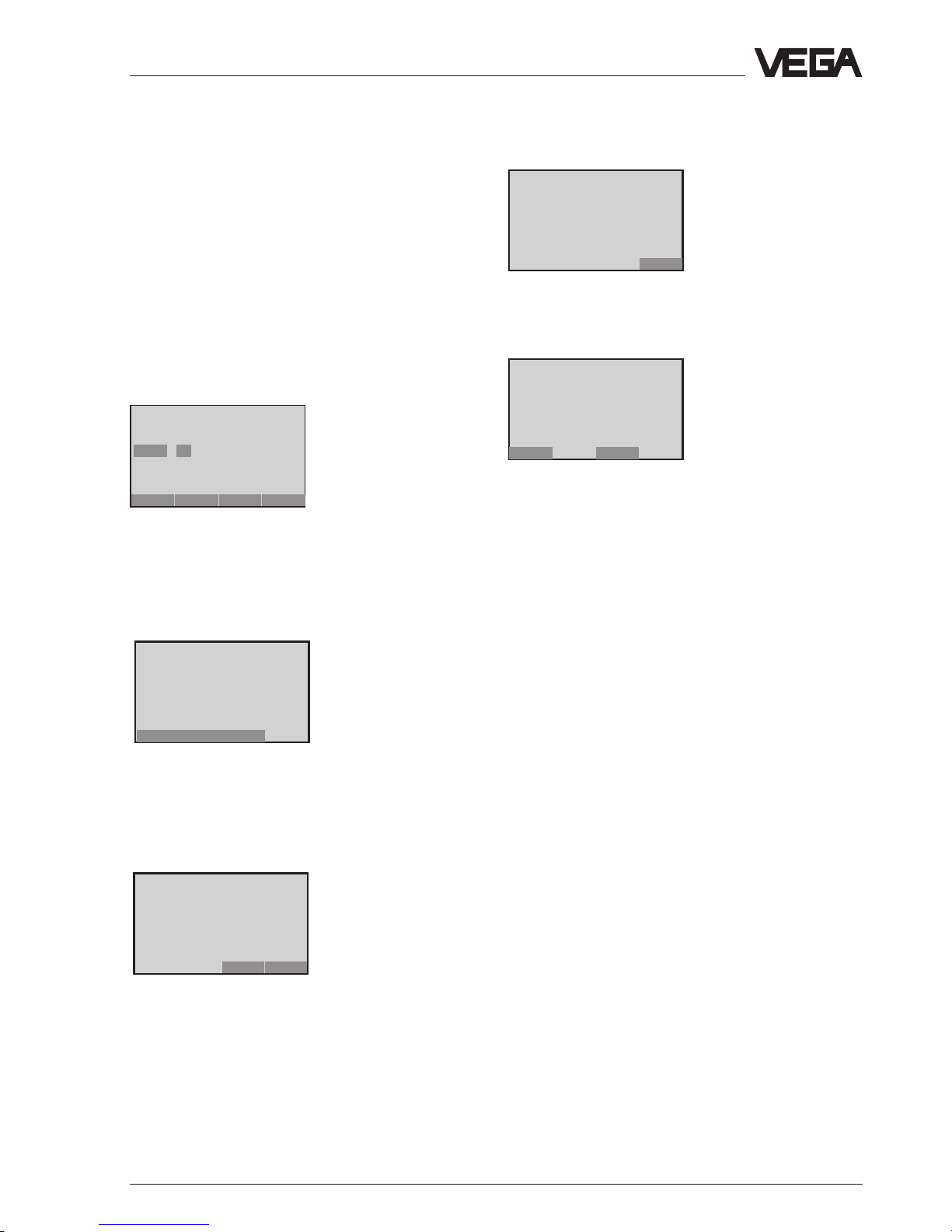
Set-up
Note
When the resistance of the voltage supply is
less than 250 Ω, a resistor must be looped into
the signal/connection line during adjustment.
The digital adjustment and communication
signals would be shortcircuited via too small
resistors e.g. of the supply current source or the
processing system so that the sensor
communication would not be ensured. The
easiest way would be to connect the required
adjustment resistor in parallel to the connection
sockets of the HART®-handheld (see fig. 1).
• Switch on the power supply of the connected
sensor.
• Start the adjustment software VVO (VEGA
Visual Operating) on your PC.
• In the entrance window you choose with the
arrow keys or the mouse the point
Planning
and click to OK.
You should only choose
Planning
when you
are authorized to modify instrument
parameters. Otherwise choose
Operator
or
Maintenance
.
In the window User identification you are
asked for the name and the password.
• For set-up (
planning
) enter under name:
VEGA
and under password again:
VEGA
. It
does not matter if you use capital or small
letters.
4
3
2
1
+ - + -
PC with VVO
mA
approx.
250 Ω
Page 31

Capacitive electrodes EL 4 … 20 mA - compact 31
Measuring system
In this sensor you can choose your appropriate
electrode. You can see the electrode type on
the type plate of the instrument.
Choose the correct electrode out of the list, e.g.
EL 21 14 mm PTFE. In front of the listed
electrodes you see the number of the electrode
type. The number to your electrode is stated on
the type plate. See also 1.6 Type plate. When
your electrode is not stated in the list, choose
´not configured´
. Push the button for saving to
confirm the choice.
In this window you can carry out additionally a
reset. All adjusted values are then reset to
factory setting. Note that also the adjustment
will be deleted.
Tag number, measurement loop designation
etc. from the HART® or VVO-adjustment
however remain unchanged.
Factory Setting
0 Operate --1 Min. adjustment 4 mA at 0 pF
2 Max. adjustment 20 mA at 3000 pF
3 Integration time 0,5 s
4 Reverse characteristics 4 ... 20 mA
5 Linearisation off
6 Sensor optimization mode 1 (90°)
7 Simulation current off
8 Reset --9 Offset correction already saved values
remain
Measurement loop
In this window you can make the measurement
loop designation.
Measurement loop no. (Sensor-TAG)
In this field you can enter a measurement loop
number, e.g. Tank 15 - 3. Max. 16 positions are
available.
Measurement loop description
In this field you can specify your measurement
loop in detail, e.g. level measurement - cleaning
solution.
Up to 80 positions can be entered.
Application
For capacitive electrodes
Level measurement
is
fixed adjusted and cannot be modified.
Program
In this menu point you can modify the
adjustments for the program.
Language
Here you can modify the language of the program.
User access
With this function you can modify the user name
and the password or deactivate the password
request.
Set-up
Page 32
32 Capacitive electrodes EL 4 … 20 mA - compact
Communication
You can determine the adjustments for data
transmission.
Options
In this function, programm adjustments such as
activate sound, backup etc. are available.
Instrument data
Display Diagnostics Instrument data Configuration Services Quit Help
Parameter adjustment
Under the menu point instrument data you can
choose the function:
• Parameter adjustment.
Parameter adjustment
The following functions are available:
- adjustment
- conditioning
- outputs
- sensor optimization
- additional functions
Adjustment - Min./Max. adjustment
With this function you can adjust the electrode
(min./max. adjustment).
You can choose if you want to carry out the
adjustment with or without medium.
Adjustment with medium
Min. adjustment
There must be min. level in the vessel. When
you push the button
Save,
the current value for
the actual min. level is set to 4 mA. The read out
of the sensor value in pF is also possible.
You can also coordinate a certain percentage
value to a known level.
When you know e.g. that your vessel is filled to
10 %, this can be entered under min.
adjustment.
Max. adjustment
There must be max. level in the vessel. When
you push the button
Save,
the current value for
the actual max. level is set to 20 mA. The
sensor value can be also read out in pF.
You can also coordinate a certain percentage
value to a known level.
The difference between min. and max.
adjustment should be at least 20% or 3,2 mA.
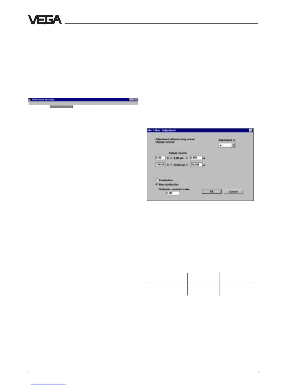
Adjustment without medium (dry
adjustment)
By means of the adjustment software VVO you
can carry out under certain requirements an
adjustment without medium.
The requirements for an adjustment in m are:
In conductive medium:
- electrode is fully insulated
For conductivity the following criteria are valid:
Mode 1 (90°) Mode 2 (45°)
with conc.tube > 50 µS/cm >150 µS/cm
without conc. tube >100 µS/cm >300 µS/cm
In non-conductive medium:
- concentric tube electrode
- you know the DK-value of the medium
Set-up
Page 33

Capacitive electrodes EL 4 … 20 mA - compact 33
When you know already the electrode
capacitance of a second similar measurement
loop (same electrode, same installation
conditions, same medium) you can also carry
out the dry adjustment in pF.
First carry out an offset correction with
uncovered electrode (only with adjustment in m:
Instrument data - Parameter adjustment - Additional functions
).
Move to function
Adjustment without medium
.
You can choose if you want to carry out the
adjustment in pF or in m. When you have
chosen the adjustment in m, you have to enter
whether your medium is conductive or nonconductive. When the medium is nonconductive you must additionally enter the
dielectric constant figure.
In the previous table you can see which criteria
are valid for the conductivity with the capacitive
measurement and if you have to choose
Conductive
or
Non-conductive.
When you have chosen m, you can coordinate
to the current or percentage values an
appropriate value in metres.
Example
0% = 4,00 mA = 0,2 m
100 % = 20,00 mA = 3,2 m
When you have chosen pF, you can coordinate
to the current or percentage values an
appropriate value in pico-farad
Example
0% = 4,00 mA = 97,2 pF
100 % = 20,00 mA = 1428,0 pF
When you push the button OK, the values are
taken over for adjustment.
Conditioning
In this window the following functions are
available:
- scaling
- linearisation
- integration time
Scaling
With this command you can scale the
measured value for your indication.
You can choose out of 16 volume, height and
mass units or just dimensionless.
The indication values can be between -10000
and +10000.
Linearisation
In this window you can linearize unlinear
vessels such as e.g. cylindrical tanks.
The following linearisation curves are available:
- linear
- cylindrical tank
- spherical tank
- user programmable curve
On oscillator CAP E32 H you can enter under
“user programmable curve“ also own
linearisation curves for special vessels, e.g.
vertical cylindrical tanks with large conical
outlet.
Push the button
Edit.
You can enter the value
pairs (percentage value - volume value) for 32
index markers.
Push the button
Transfer
, to enquire further
linearisation curves.
Integration time
Choose this function when you want to adjust
an integration time (damping).
The possible integration time is between 0,5
and 300 seconds. As a standard feature an
integration time of 0,5 seconds is adjusted. For
an integration time of 0,5 s you have to enter
the value 0.
After the adjusted integration time, a measured
value change of 63 % is available on the
output.
Set-up
Page 34
34 Capacitive electrodes EL 4 … 20 mA - compact
Output - Current output
In this window you can change the
preadjustments for the current output. Push the
button
Save
to tranfer the modified values.
Failure mode
The capacitive sensor delivers in case of failure
generally 22 mA. This value cannot be
modified.
The current output corresponds to
The parameter of the current output is always
percent with capacitive electrodes.
Invert current output
With this function you can reverse the
characteristics of the current output (4 ... 20 or
20 ... 4 mA).
Sensor optimisation
In this window you can adjust the mode of the
sensor.
Hence the phase angle of the phase selective
admittance processing (PSA) is modified.
“Mode 1“ is preadjusted.
Mode 1 = Phase angle 90°
Mode 1 is a pure capacitance measurement,
the ohmic resistance is not considered in the
measuring result.
Application:
- standard adjustment
- non-conductive liquids up to approx. 500 µS
- compensation of resistance changes in
liquids
- generally with partly insulated electrodes in
liquids
- non-conductive solids without humidity
contents
- in case of bad earth of the medium
- with electrodes in conjunction with a
concentric tube
- in non-conductive vessels with earth plate
provided from outside.
Mode 2 = Phase angle 45°
The capacitance and the ohmic resistance are
measured separately, the capacitance value is
corrected by calculation with the ohmic
resistance, so that measuring errors by
conductive build-up or modifications of the
product humity are compensated.
Application:
- high conductivity products
- adhesive, conductive products
- solids with fluctuating humidity contents
Additional functions
Offset correction
This function is required when an adjustment
should be carried out in m. This is only possible
in conjunction with oscillator CAP E 32 H Ex.
With this function the initial capacitance is
saved in the electronics. Requirement is that
the electrode is mounted in the vessel and
completely uncovered.
The offset correction is necessary when an
adjustment should be carried out without
medium.
On electrodes with concentric tube, this
function is already carried out as factory setting
as the vessel does not influence the
measurement.
The offset correction must only be repeated
when the oscillator is exchanged.
Display
Display Diagnostics Instrument data Configuration Services Quit Help
Display of measured value
Under the menu point display you can choose
the function:
• Display of measured value.
Display of measured value
In this window the actual measured value is
displayed digitally and as bargraph.
The upper bar shows the actual measured
value in percent, pF or scaled in the
appropriate unit.
The lower bar shows the actual sensor current
value in mA.
Set-up
Page 35
Capacitive electrodes EL 4 … 20 mA - compact 35
Diagnostics
Display Diagnostics Instrument data Configuration Services Quit Help
Status
Si
mulation
Under the menu point diagnostics you can
choose the following functions.
• status
• simulation
Status
This function is not available.
Simulation
With this function you can simulate a level. Push
the start button to activate the simulation. Shift
the scrollbar to the requested current value or
enter a certain current value. The scaled
indication bar is modified in parallel.
Push the button
Stop
to interrupt the simulation.
When you quit the window
Simulation,
the
simulation is automatically interrupted.
Services
Display Diagnostics Instrument data Configuration Services Quit Help
Print
View
Backup >
Restore configuration >
Edit database
User level
Connection F8
Modem F7
Signal conditioning
instruments
Sensors
Under the menu point services you can choose
the following functions:
• print
• view
• backup
• restore configuration
• edit database
• user level
• connection
• modem
Set-up
Print
With this function you can print a protocol with
the adjustments of the sensor.
View
With this function you can have the protocol
with the sensor adjustments displayed.
Backup - Sensors
In this window you can save the adjustments of
the sensor in a database.
Restore configuration - Sensors
In this window you can enquire the adjustments
of the sensor from the database.
Edit database
In this window you can edit the saved sensor
data of the database.
User level
In this window you can choose the user level.
The following user levels are available:
- operator
- maintenance
- planning
Operator
This user level is for the operator. Indication
or print out of measured values and sensor
data. For this level there is no password
required.
Maintenance
When you use the level maintenance, you can
choose all functions except configuration.
The password for this level is: VEGA.
Planning
When you choose the level planning all
functions are accessible.
The passwords for the planning level are:
VEGA - VEGA.
Connection
Page 36

36 Capacitive electrodes EL 4 … 20 mA - compact
4.4 Adjustment with HART®handheld
The capacitive electrodes EL with oscillator
CAP E32 H Ex are suitable for HART®-protocols
and can be adjusted with a HART®-handheld.
All relevant sensor functions can be carried out
with the HART®-standard menus. A
manufacturer specific DDD (Data-DeviceDescription) is not necessary.
Connect the HART®-handheld to the signal line
after you have connected the sensor to the
supply voltage.
4
3
2
1
+ - + -
mA
250 Ω
HART®-handheld
With this function you can start a new
connection. This function can also be activated
with key F8.
Modem
This window enables the adjustments for data
transmission with a modem. This function can
also be activated with key F7.
No special requirements necessary for the
modem used.
Note
When the resistor of the supply voltage is less
than 250␣ Ω, a resistor must be looped into the
signal/connection line during adjustment. The
digital adjustment and communication signals
would be shortcircuited via too small resistors
e.g. of the current source or the processing
system so that the sensor communication
would no more be ensured. The easiest way
would be to connect the required resistor in
parallel to the socket of the HART®-handheld
(see fig. 1, page 38).
Set-up
Multidrop-operation
With the HART®-handheld the Multidropoperation can be chosen.
Hence several HART®-sensors can be
composed on one two-wire line.
The sensor provides beside the 4 … 20 mAsignal also a digital (HART®) level signal.
• When you enter address 0 (factory setting),
the sensors takes a level independent 4 …
20 mA-current and delivers a digital (HART®)
level signal. In this line e.g. also an indicating
instrument (4 … 20 mA) can be looped.
• When you enter an address from 1 to 15, the
sensor takes permanently a current of 4 mA
and delivers a digital (HART®) level signal.
Burst-operation
Normally the sensor signals the measured
values to the processing unit only on request.
When you switch on Burst-operation, the sensor
signals the measured values without request.
Page 37

Capacitive electrodes EL 4 … 20 mA - compact 37
Connection to a VEGA-signal conditioning
instrument
(fig. 3, page 38)
When you operate a sensor suitable for HART
®
on a VEGA-signal conditioning instrument, you
have to provide the sensor connection on the
signal conditioning instrument with a resistor of
the following table for the duration of the
HART®-adjustment.
VEGA-signal conditioning Rx
instrument
VEGAMET 513, 514, 515, 602
VEGATRENN 544
VEGATOR 521…527 50 … 100 Ω
VEGAMET 614 no additional
VEGADIS 371 resistor
required
VEGAMET 601 200 … 250 Ω
VEGASEL 643 150 … 200 Ω
VEGAMET 513 S4, 514 S4
515 S4 100 … 150 Ω
Set-up
Page 38

38 Capacitive electrodes EL 4 … 20 mA - compact
Ri > 250
+
–
Fig. 2
DCS
Fig. 3
+
–
VEGALOG VEGAMET
250
Ri < 250
+
–
Fig. 1
DCS
Set-up
250 Ω
Page 39
Capacitive electrodes EL 4 … 20 mA - compact 39
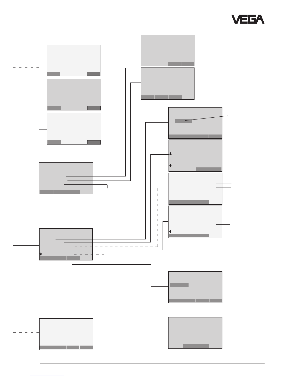
Set-up
Adjustment steps
On the following pages you see the menu plan
to the HART®-handheld in relation with
capacitive electrodes.
The most important adjustment steps are
marked in the menu plan with the figures
A␣ …␣ D.
General information to the HART®-handheld:
When you enter or modify parameters, you
have to push the key “
ENTER
“. Hence the
adjustment is saved in the handheld but not in
the sensor itself.
After you have pushed “
ENTER
“, you have to
push “
SEND
“, to transfer the adjustment to the
sensor.
After pushing of “
SEND
“ a warning is
displayed.
When you push “OK“, the adjustment is
transmitted to the sensor.
Another safety enquiry asks you to switch over
your system from manual to automatic
operation. Push “
OK“
With
“HOME“
you reach again the initial menu.
Generic: SENSOR
PV LRV
0.000 m
10.000
HELP DEL ABORT ENTER
4.1
(5.1)
Empty adjustment without
medium
Generic: SENSOR
1PV LRV
2PV URV
HELP SEND HOME
Generic: SENSOR
- WARNINGPressing ”OK“ will
change device output.
Put loop in manual
ABORT OK
Generic: SENSOR
- WARNING-
Return control loop to
automatic control.
OK
Generic: SENSOR
1PV LRV
2PV URV
HELP HOME
Page 40

40 Capacitive electrodes EL 4 … 20 mA - compact
Set-up
HART®-menu plan
A
1
2
3
4
5
1.1
4.1
(5.1)
4.2
(5.2)
Less important
menu windows
Not required,
unimportant or blocked
menu windows
Important and
necessary menu
windows
B
Switch on:
after approx.
20 s
Set-up the sensor in the sequence of
the figures A, B, C and D (adjustment
without medium).
In case of adjustment with medium, setup the sensor in the sequence A1, B1,
C and D.
continue like under A
figure 4.1(5.1)
Empty adjustment
without medium
Full
adjustment
without
medium
continue like under
figure 4
Hart Communicator
Self Test
in Progress
Firmware Rev: F2.2
Module Rev: 3.6
01992-96 FRSI
Generic: Sensor
PV
2,56 m
HELP EXIT
Generic: Sensor
Device setup
1 Process variables
2 Diag/Service
3 Basic setup
4 Detailed setup
5 Review
SAVE HOME
Generic: Sensor
PV URV
100.000 m
90.300
HELP DEL ESC ENTER
Generic: Sensor
Process variables
1 Snsr 2,56 m
2 AI % rnge
3 AO1
HELP SAVE HOME
Generic: Sensor
Online(Generic)
1 Device setup
2PV
3PVAO
4PVLRV
5URV
HELP SAVE
Generic: Sensor
AO1
16.952 mA
HELP EXIT
Generic: Sensor
1 PV LRV
2URV
HELP SEND HOME
Generic: Sensor
PV LRV
0.000 m
10.000
HELP DEL ESC ENTER
Generic: Sensor
1 PV LRV
2URV
HELP SEND HOME
Page 41
Capacitive electrodes EL 4 … 20 mA - compact 41
Set-up
blocked menu.
6 PV Damping
1.1.3
1.2
1.3
1.4
1.5
1.1.2
1.1.1
1.3.1
1.3.2
1.3.3
1.3.4
1.3.6
6 Write protect None
7 Descriptor
8 Message
9 PV Snsr s/n
Final asmbly num
Revision’s
1.2.3
1.2.2
Individual current values for
test purposes (simulation of
measured values)
Empty and full
adjustment
with medium
(see next
page)
see
next
page
see next
page
C
D
new entered
measuring loop
designation to be
confirmed with
ENTER and SEND
}
}
see
next
page
}
Transmission function
(linear)
Confirm
safety
enquiry
A1
B1
}
Generic: Sensor
Detailed setup
1 Sensors
2 Signal condition
3 Output condition
4 Device information
SAVE HOME
Generic: Sensor
PV
0,2 m
HELP EXIT
Generic: Sensor
PV % rnge
8.945 %
HELP EXIT
Generic: Sensor
AO1
5.952 mA
HELP EXIT
Generic: Sensor
PV Snsr unit
m
m
bbl
in
cm
ESC ENTER
Generic. Sensor
Range values
1 PV LRV
2URV
3 PV LSL
4 USL
HELP HOME
Generic: Sensor
PV Damp
1.000 s
2 .000 s
HELP DEL ESC ENTER
Generic: Sensor
Basic setup
1Tag
2 PV Unit
3 Range values
4 Device information
5 PV Xfer fnctn
HELP SAVE HOME
Generic: Sensor
Review
Model
Generic
HELP PREV NEXT EXIT
Generic: Sensor
Calibration
1 Apply values
2 Enter values
HELP SAVE HOME
Generic: Sensor
Choose analog output
level
14 mA
2 20 mA
3 Other
4 End
ABORT ENTER
Generic: Sensor
Diag/Service
1 Test device
2 Loop test
3 Calibration
4 D/A trim
SAVE HOME
Generic: Sensor
Device information
1 Distributor
2 Model Generic
3 Dev id
4Tag
5 Date 10/01/97
HELP SAVE HOME
Generic: Sensor
Tag
Sensor
Sensor
HELP DEL ESC ENTER
Page 42

42 Capacitive electrodes EL 4 … 20 mA - compact
Set-up
1.3.3
1.3.4
6 Write protect None
7 Descriptor
8 Message
9 PV Snsr s/n
Final asmbly num
Revision’s
1.4
like menu 1.3.4
1.2.3.2
as display 4.1
as display 4.2
1.2.3
1.2.3.1
Confirm
safety
enquiry
Indication of sensor
meas. range limits
Indication of sensor
measuring range limits
(1.3.4.5) Date
Individual text
Measured value
Change unit
Info on lower and upper meas.
range limit as well as the min.
span (also sensor
characteristics values)
1.4.1
1.4.2
Adjustment of the integration time
Adjustment of zero and span
Adjustment of zero and span
linear
Level indication in % of the
adjusted span
1.4.3
Menu field with broken line:
Repetition from previous page
}
1.3.3.1
1.3.3.2
Indication of the sensor serial number (as menu window 1.3.4.3)
unknown (Unknown Enumerator)
General
Individual text
None
Empty adjustment with
medium
Full adjustment with
medium
(1.3.4.4) Measurement loop designation as under 1.3.1
(1.3.4.3) Indication of the sensor serial number
}
A1
B1
1.2.3.1
HART®-menu plan (continuation)
Generic: Sensor
Range values
1 PV LRV
2 PV URV
3 PV LSL
4 USL
HELP HOME
Generic: Sensor
Device information
1 Distributor
2 Model Generic
3 Dev id
4Tag
5 Date 01/01/97
HELP SAVE HOME
Generic: Sensor
Detailed setup
1 Sensors
2 Signal condition
3 Output condition
4 Device information
SAVE HOME
Generic: Sensor
PV LRV
0.000 mbar
10.000
HELP DEL ESC ENTER
Generic: Sensor
PV URV
100.000 m
90.300
HELP DEL ESC ENTER
Generic: Sensor
Sensors
1PV
2 PV Snsr unit
3 Sensor information
HELP SAVE HOME
Generic: Sensor
Signal condition
1 Snsr Damp 1.000 s
2URV
3 AI LRV
4 Xfer fnctn Linear
5 AI % rnge
HELP SAVE HOME
Generic: Sensor
Output condition
1 Analog output
2 HART output
SAVE HOME
Generic: Sensor
Enter values
1 PV LRV
2URV
3 PV USL
4 PV LSL
HELP SEND HOME
Generic: Sensor
Calibration
1 Apply values
2 Enter values
HELP SAVE HOME
Generic: Sensor
Apply new 20 mA input
ABBR. OK
Generic: Sensor
Apply new 4 mA input
ABORT OK
Generic: Sensor
Set the:
14 mA
2 20 mA
3 Exit
ABORTENTER
Page 43

Capacitive electrodes EL 4 … 20 mA - compact 43
Set-up
1.2.3.1.1
1.2.3.1.2
Note:
After adjustment of a parameter push ”
ENTER
“ and then ”
SEND
“.
Confirm the message to switch over the meas. circuit to manual operation with
”OK“.
Confirm the message to change over to automatic operation also with ”OK“.
Only then the adjustment is written in the sensor and is effective.
Menu windows are displayed but not
supported by the sensor.
Saving of the adjustments carried out
here, is hence not possible.
1.4.3.1.3
1.4.3.1.2
High: Current output goes to < 3,6
mA
in case of failure
1.4.3.2
1.4.3.1
}
Off
On
Not used
None
Unknown
Special
Sensor signals measured values only
upon request
Sensor signals measured values
unsolicited
Choice is not supported
1.4.3.2.3
1.4.3.2.4
Burst mode should be off
Choice is not supported
1.2.3.1.1.1
1.2.3.1.2.1
1.4.3.1.3
1.4.3.1.3.1
Generic: Sensor
Current applied
process value: 10.945
mbar
1 Set as 4 mA value
2 Read new value
3 Leave as found
ABORT ENTER
Generic: Sensor
Current applied
prosess value :85.281
mbar
1 Set as 20 mA value
2 Read new value
3 Leave as found
ABORT ENTER
Generic: Sensor
Choose analog output
level
14 mA
2 20 mA
3 Other
4 End
ABORTENTER
Generic: Sensor
WARN - Loop should be
removed from
automatic control
ABORT OK
Generic: Sensor
Set the:
14 mA
2 20 mA
3 Exit
ABORT ENTER
Generic: Sensor
Set the:
14 mA
2 20 mA
3 EXIT
ABORT ENTER
Generic: Sensor
AO Alrm typ
Hi
EXIT
Generic: Sensor
HART output
1 Poll addr
2 Num req preams
3 Burst mode
4 Burst option
HELP SAVE HOME
Generic: Sensor
Analog output
1 AO1 13.467
2 AO Alrm typ
3 Loop test
4 D/A trim
5 Scaled D/A trim
HELP SAVE HOME
Generic: Sensor
Fld dev output is
fixed at 4.000 mA
ABORT OK
Generic: Sensor
Burst mode
Off
Off
On
Not Used
None
ESC ENTER
Generic: Sensor
Burst option
*********
PV
% range/current
Process vars/crnt
HELP ESC ENTER
Page 44

44 Capacitive electrodes EL 4 … 20 mA - compact
Diagnosis
5 Diagnosis
5.1 Simulation
To simulate a certain filling, you can enquire the
function simulation on the oscillator, in the
adjustment program VVO or in the HART®-handheld.
Then you simulate a certain current. Note that
connected instruments such as e.g. a DCS
react according to their adjustment and trigger
if necessary alarm functions or activate system
functions.
5.2 Maintenance
The instrument is maintenance free.
5.3 Repair
Due to safety and guarantee reasons repair
work beside the wiring must only be made by
VEGA-staff.
In case of a defect, please return the
appropriate instrument with a short description
of the error to our repair department.
Failures are shortterm malfunctions of the
instrument which are caused by wrong
adjustment or defects on the sensor or the
connection lines.
Failures, possible reasons and their removal are
stated under “5.4 Failure removal“.
Page 45

Capacitive electrodes EL 4 … 20 mA - compact 45
28
30
32
+
–
+
–
+
–
mA
V
4 … 20 mA 12 … 20 V
Sensor
Diagnosis
5.4 Failure removal
Failure Measure, failure removal
Current value Check the sensor inputs on the following failures:
≥ 22 mA - shortcircuit on the input
- sensor not correctly connected
- sensor line interrupted
- supply voltage too low or too high
Measure the current on the connection line to the sensor.
The terminal voltage on the sensor in standard condition is at least 12␣ V.
Note with Ex-systems that the Ex-protection is not influenced by
the measuring instruments.
Current value > 22 mA
- Check all connections and the connection line to the sensor.
- Loosen the two small screws with a screwdriver and remove the
oscillator out of the plug connection.
- Measure the current.
• When the current value remains > 22 mA, the oscillator is defect.
Exchange the oscillator.
• When the current value is < 22 mA, the electrode is defect. Return
the electrode for repair.
z.B. VEGATOR
12 … 36 V
Page 46

46 Capacitive electrodes EL 4 … 20 mA - compact
Diagnosis
Failure Measures, failure removal
Sensor defect, Test of the internal connections:
measurement does • Loosen the 4 screws of the housing cover with a screwdriver and
not react to level remove the housing cover.
changes • Loosen the two small screws with a screwdriver and pull the oscillator
out of the housing.
• Measure with an Ohm-Meter (range MΩ) the resistance values
between the following contacts:
CM - Meas. capacitor
4
6
C
M
1 M
Screen
Contact 4 against middle pin (1)
The resistor must be 1␣ MΩ .
If the resistor is less, this means humidity in the housig or a failure in the
electrode isolation. A possible reason could be a not isolated electrode
which is used in conductive (humid) product.
If the resistor is higher or if the connection is interrupted, the reason is
mainly a bonding failure in the adapter plate or a defect resistor due to
strong electrostatic discharge.
In both cases the electrode must be repaired at VEGA.
Page 47

Capacitive electrodes EL 4 … 20 mA - compact 47
Diagnosis
Contact 4 against vessel
The connection between contact 4 and the metal vessel (not instrument
hexagon or electrode flange) should be as good as possible. Measure with
an ohmmeter (range very low) the resistance value between contact 4 and
the vessel.
• Shortcircuit (0␣ …␣ 3␣ Ω), optimum connection
• Resistance >␣ 3␣ Ω
- corrosion on the mounting boss or flange
- probably the mounting boss was covered with Teflon tape or similar
Check the connection to the vessel. If there is no connection, you can
connect a line from the earth terminal outside to the vessel.
Note that coated flanges must be in any case connected via the earth
terminal to the vessel.
Contact 4 against 6
In case of values > 3 Ω there is a defect.
When you cannot find a failure in the electrode, than exchange the
oscillator against a similar replacement type (if available) or send the
electrode for repair to VEGA.
After insertion of the new electronics, carry out an adjustment. See 4 Setup.
VVOfailure message
Meas. value invalid
Measured value invalid
The actual measured value is not within the valid measuring range.
Reasons can be e.g. extreme modifications of the dielectric constant figure
or wrong adjustments.
Modify the actual measuring conditions.
Page 48

48 Capacitive electrodes EL 4 … 20 mA - compact
Diagnosis
Instrument failure
No failure detected on the sensor.
Possible reasons are:
- supply voltage outside the tolerance
- defect oscillator
- damage of the electrode or the isolation
- electrode shortcircuited with the vessel wall
• Separate the sensor from the supply voltage and then connect voltage
again (cold start).
• If the fault signal does not extinguish, check the sensor line and the
correct supply voltage.
• If the fault signal does not extinguish, check the sensor on damages.
If you cannot detect any failure, call our service department.
VVOfailure message
Instrument failure
Page 49

Capacitive electrodes EL 4 … 20 mA - compact 49
Notes
Page 50

50 Capacitive electrodes EL 4 … 20 mA - compact
Notes
Page 51

Capacitive electrodes EL 4 … 20 mA - compact 51
Notes
Page 52

HiTECH Technologies, Inc.
301 Oxford Valley Road - Building 505
Yardley, PA 19067-7706
Tel: 215. 321. 6012; Fax: 215. 321. 6067
Tech Support (Toll Free) 866-DrLevel or 888-NIVELCO
Email: info@DrLevel.com or info@hitechtech.com
Web Site: www.DrLevel.com or www.hitechtech.com
A TECHNOLOGY FOR
EVERY LEVEL APPLICATION
 Loading...