

Page 1
Operating Instructions
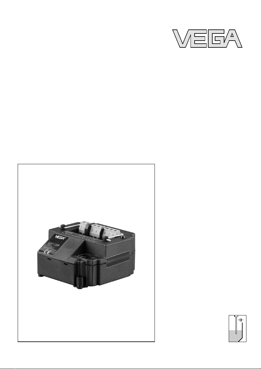
Electronics module
CAP
E31R
Capacitive
Page 2

Contents
1 About this document
1.1 Function .
. . . . . . . . . . . . . . . . . . . . . . . . . . . .
4
1.2 Target group . . . . . . . . . . . . . . . . . . . . . . . . . .
4
1.3 Symbolism used . . . . . . . . . . . . . . . . . . . . . . .
4
2 For your safety
2.1 Authorised personnel . . . . . . . . . . . . . . . . . . . .
5
2.2 Appropriate use . . . . . . . . . . . . . . . . . . . . . . . .
5
2.3 Environmental instructions . . . . . . . . . . . . . . . .
5
3 Product description
3.1 Configuration. . . . . . . . . . . . . . . . . . . . . . . . . .
6
3.2 Principle of operation . . . . . . . . . . . . . . . . . . . .
6
3.3 Packaging, transport and storage . . . . . . . . . . .
6
4 Mounting
4.1 Mounting instructions . . . . . . . . . . . . . . . . . . . .
8
4.2 Mounting preparations . . . . . . . . . . . . . . . . . . .
8
4.3 Mounting steps . . . . . . . . . . . . . . . . . . . . . . . .
8
5 Setup
5.1 Setup . . . . . . . . . . . . . . . . . . . . . . . . . . . . . . .
10
6 Maintain
6.1 Instrument repair . . . . . . . . . . . . . . . . . . . . . . .
12
7 Dismounting
7.1 Dismounting steps . . . . . . . . . . . . . . . . . . . . . .
13
7.2 Disposal . . . . . . . . . . . . . . . . . . . . . . . . . . . . .
13
8 Supplement
8.1 Technical data. . . . . . . . . . . . . . . . . . . . . . . . .
14
2 Electronics module - CAP E31R
Contents
33761-EN-070809
Page 3
1 About this document
1.1 Function
This
operating instructions manual has all the information you
need for quick mounting and setup of a replacement module.
Please read this manual before you start setup.
1.2 Target group
This operating instructions manual is directed to trained
personnel. The contents of this manual should be made
available to these personnel and put into practice by them.
1.3 Symbolism used
Information, tip, note
This symbol indicates helpful additional information.
Caution: If this warning is ignored, faults or malfunc-
tions can result.
Warning: If this warning is ignored, injury to persons and/or
serious damage to the instrument can result.
Danger: If this warning is ignored, serious injury to persons
and/or destruction of the instrument can result.
Ex applications
This symbol indicates special instructions for Ex applications.
l List
The dot
set in front indicates a list with no implied sequence.
à Action
This arrow
indicates a single action.
1 Sequence
Numbers set in front indicate successive steps in a procedure.
Electronics module - CAP E31R 3
About this document
33761-EN-070809
Page 4

2 For your safety
2.1 Authorised personnel
All
operations described in this operating instructions manual
must be carried out only by trained specialist personnel
authorised by the operator.
During work on and with the device the required personal
protection equipment must always be worn.
2.2 Appropriate use
Oscillator CAP E31R is a replacement oscillator VEGACAP
27, 35 and 98 capacitive level switches.
2.3 Environmental instructions
Protection of the environment is one of our most important
duties. That is why we have introduced an environment
management system with the goal of continuously improving
company environmental protection. The environment management system is certified according to DIN EN ISO 14001.
Please help us fulfil this obligation by observing the environmental instructions in this manual:
l Chapter "Packaging, transport
and
storage"
l Chapter "Disposal"
4 Electronics module - CAP E31R
For your safety
33761-EN-070809
Page 5

3 Product description
3.1 Configurat
ion
The scope of delivery encompasses:
l Oscillator CAP
E31R
l Documentation
- this operating instructions manual
3.2 Principle of operation
Oscillator CAP E31R is suitable for exchange with VEGACAP
27, 35 and 98 capacitive level switches.
3.3 Packaging, transport and storage
Your instrument was protected by packaging during transport.
Its capacity to handle normal loads during transport is assured
by a test according to DIN EN 24180.
The packaging of standard instruments consists of environ-
ment-friendly, recyclable cardboard. For special versions, PE
foam or PE foil is also used. Dispose of the packaging material
via specialised recycling companies.
Transport must be carried out under consideration of the notes
on the transport packaging. Nonobservance of these instructions can cause damage to the device.
The delivery must be checked for completeness and possible
transit damage immediately at receipt. Ascertained transit
damage or concealed defects must be appropriately dealt
with.
Up to the time of installation, the packages must be left closed
and stored according to the orientation and storage markings
on the outside.
Unless otherwise indicated, the packages must be stored only
under the following conditions:
l Not
in the open
l Dry and dust free
l Not exposed to corrosive media
l P
rotected against solar radiation
l Avoiding mechanical shock and vibration
Sco
pe of delivery
Area of application
Packaging
Transport
Transport inspection
Storage
Electronics module - CAP E31R 5
Product description
33761-EN-070809
Page 6

l Storage and transport temperature see "Supplement -
Technical data - Ambient conditions"
l Relative humidity 20 … 85 %
Stora
ge and transport tem-
perature
6 Electronics module - CAP E31R
Product description
33761-EN-070809
Page 7

4 Mounting
4.1 Mounting
instructions
If the electronics module is defective, it can be replaced by the
user.
In Ex applications only one instrument and one oscillator with
respective Ex approval may be used.
4.2 Mounting preparations
If it is necessary to exchange the oscillator, you should use an
oscillator type CAP E31R.
4.3 Mounting steps
Proceed as follows to exchange the oscillator:
1 Switch off power supply
2 Loosen the four screws of the housing cover with a Phillips
screwdriver.
3 Remove the housing cover
4 Loosen the screws of the terminals with a Allen wrench.
5 Pull the connection cables out of the terminals.
6 Loosen the two screws with a Phillips screwdriver.
7 Open the tensile ring on the old oscillator and pull out the
old oscillator.
8 Compare the new oscillator with the old one. The type label
of the oscillator must correspond to that of the old
oscillator.
9 Insert the new oscillator.
10 Screw in and tighten the two screws with a Phillips
screwdriver.
11 Lead the connection cable through the cable gland.
12 Insert the wire ends into the open terminals according to
the wiring plan and tighten them.
13 Check the hold of the wires in the terminals by lightly
pulling on them.
14 Turn the cable gland right back and check the tightness.
The seal ring must completely encircle the cable.
15 Carry out a fresh adjustment. See chapter "Set up, new
Mounting steps
Electronics module - CAP E31R 7
Mounting
33761-EN-070809
Page 8

adjustment".
16 Retighten the housing cover
The electronics exchange is now finished.
8 Electronics module - CAP E31R
Mounting
33761-EN-070809
Page 9

5 Setup
5.1 Setup
Proceed as
follows for a fresh adjustment:
3
4
5
6
1
2
Fig. 1: Oscillator with relay output
1 Type label
2 Connection terminals
3 Tensile proving ring
4 Control lamp
5 DIL switch for mode adjustment
6 Potentiometer for switching point adaptation
1 Make sure that the probe is uncovered.
2 Pierce the cover of the potentiometer (6) with a screw-
driver.
3 Turn the below potentiometer (6) first of all anticlockwise
(max. 20 turns) until the control lamp signals "covered".
Mode A (overfill protection) = control lamp lights
Mode B (dry run protection) = control lamp extinguishes
If this condition is already reached, you can continue with
the next step.
4 Turn the potentiometer (6) very slowly (due to the damping)
clockwise until the control lamp signals "uncovered".
Mode A (overfill protection) = control lamp extinguishes
Mode B (dry run protection) = control lamp lights
Fresh adjustment
Electronics module - CAP E31R 9
Setup
33761-EN-070809
Page 10

5 Turn the potentiometer (6) clockwise according to the
following chart.
6 The probe is now ready for operation.
Sensitivity
Standard very sensitive
VEGACAP 27, 98
DK value >2
= 2 turns
DK value >1.5
= 1 turn
VEGACAP 35
DK value >1.5
= 2.5 turns
-
Tab. 1: Number of additional turns for the potentiometer (6)
Note:
With the measurement of products with very low dielectric
values, the number of turns can be reduced up to 1 according
to the chart.
This setting is too sensitive with conductive, adhesive
products.
Note:
When placing the housing cover, make sure that the inspection
glass is above the signal lamp of the oscillator.
10 Electronics module - CAP E31R
Setup
33761-EN-070809
Page 11

6 Maintain
6.1 Instrum
ent repair
If a repair is necessary, please proceed as follows:
You can download a return form (23 KB) from the Internet on
our homepage
www.vega.com under: "Downloads - Forms
and certificates - Repair form".
By doing this you help us carry out the repair quickly and
without having to call back for needed information.
l Print and fill
out one form per instrument
l Clean the instrument and pack it damage-proof
l Attach the completed form and, if need be, also a safety
data sheet outside on the packaging
l Please ask the agency serving you for the address of your
return
shipment. You can find the respective agency on our
website
www.vega.com under: "Company - VEGA world-
wide"
Electronics module - CAP E31R 11
Maintain
33761-EN-070809
Page 12

7 Dismounting
7.1 Dismounting steps
Take
note of chapters "Mounting" and "Connecting to power
supply" and carry out the listed steps in reverse order.
7.2 Disposal
The replacement module consists of materials which can
recycled by specialised recycling companies. We have
purposely designed the electronic modules to be easily
separable.
WEEE directive 2002/96/EG
This instrument is not subject to the WEEE directive 2002/96/
EG and the respective national laws (in Germany, e.g.
ElektroG). Pass the instrument directly on to a specialised
recycling company and do not use the municipal collecting
points. T hese may be used only for privately used products
according to the WEEE directive.
Correct disposal avoids negative effects to persons and
environment and ensures recycling of useful raw materials.
Materials: see chapter "Technical data"
If you cannot dispose of the replacement component properly,
please contact us about disposal methods or return.
12 Electronics module - CAP E31R
Dismounting
33761-EN-070809
Page 13

8 Supplement
8.1 Technical
data
Technical data
are stated in the operating instructions manual of the appropriate sensor.
Electronics module - CAP E31R 13
Supplement
33761-EN-070809
Page 14

14 Electronics module - CAP E31R
Supplement
33761-EN-070809
Page 15

Electronics module - CAP E31R 15
Supplement
33761-EN-070809
Page 16

VEGA Grieshaber KG
Am Hohenstein 113
77761 Schiltach
Germany
Phone +49 7836 50-0
Fax +49 7836 50-201
E-mail: info@de.vega.com
www.vega.com
ISO 9001
All statements concerning scope of delivery, application,
practical use and operating conditions of the sensors and
processing systems correspond to the information avail-
able at the time of printing.
© VEGA Grieshaber KG, Schiltach/Germany 2007
Subject to change without prior notice 33761-EN-070809
 Loading...