

Page 1
Operating Instruction
VEGADIS 50 Ex
Level and Pressure
8888
Page 2

Contents
Safety information ........................................................................ 2
Note Ex-area ................................................................................ 2
1 Product description
1.1 Function and configuration .................................................. 3
1.3 Technical data....................................................................... 3
1.2 Types and versions ............................................................. 3
1.4 Dimensions ........................................................................... 4
2 Mounting
2.1 Mounting instructions ............................................................ 5
3 Electrical connection ................................................................ 5
4 Set-up
4.1 Indicating and adjustment elements .................................. 6
4.2 Adjustment structure ........................................................... 7
Contents
Safety information
The described module must only be installed
and operated as described in this operating
instruction. Please note that other action can
cause damage for which VEGA does not take
responsibility.
2 VEGADIS 50
Note Ex-area
Please note the attached approval documents
(yellow binder) and especially the included
safety data sheet.
Page 3
Product description
1 Product description
1.1 Function and configuration
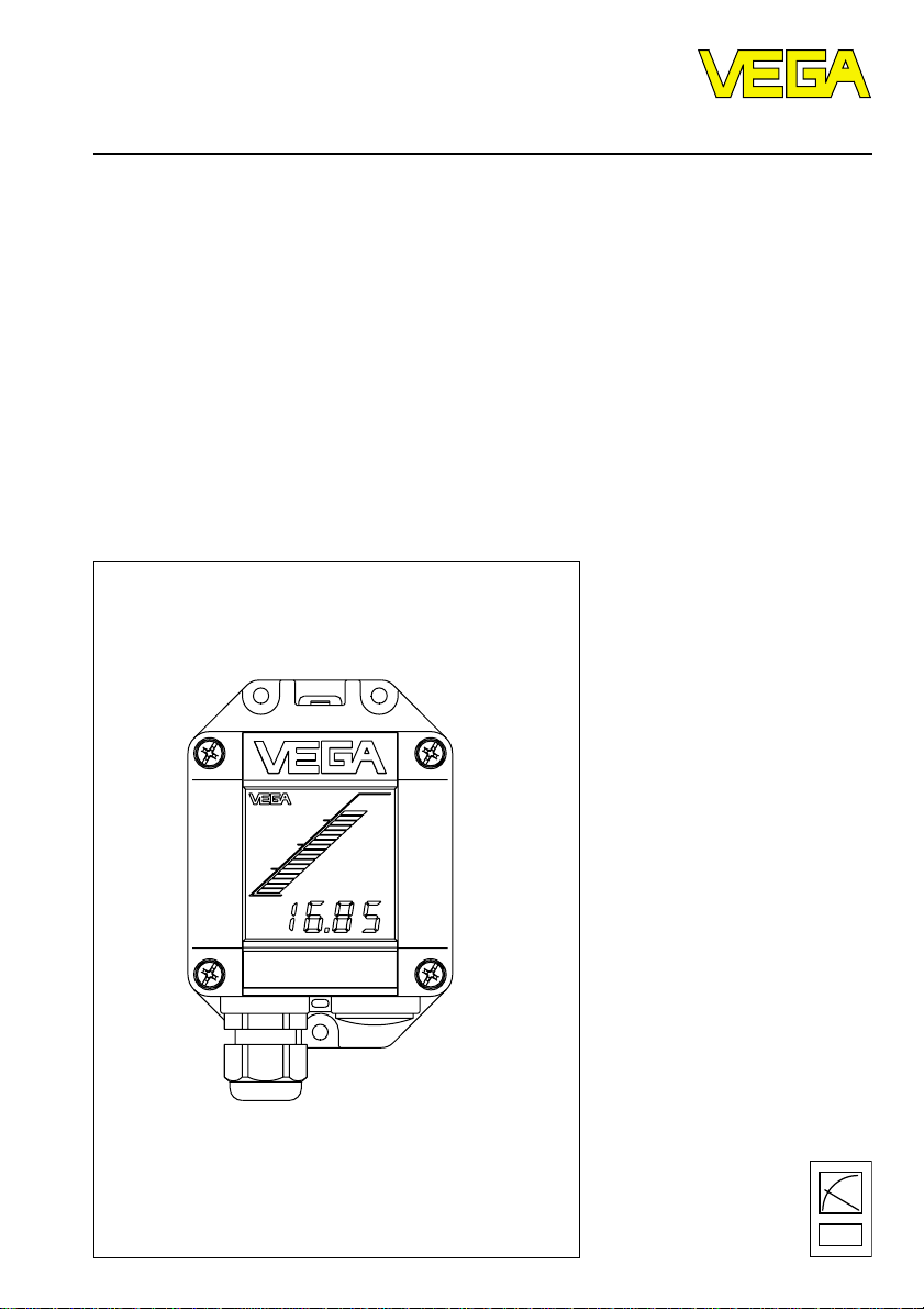
VEGADIS 50 is a digital indicating instrument
without external energy with adjustment possibility for surface or rail mounting with
LC-display for digital and quasianalogue
indication.
The indicating instrument can be connected
to all series 50 sensors (VEGASON,
VEGAPULS, VEGAFLEX) and to radar sensor VEGAPULS 81.
1.2 Types and versions
VEGADIS 50
Digital indicating instrument without external
energy for surface mounting.
With Ex-approval for surface mounting and
for mounting in zone 1 or zone 0.
Approval
EC-type approval
II 1G EEx ia IIC
TÜV 98 ATEX 1361 X.
Function
The indicating instrument VEGADIS enables
the indication of values between -9999 and
9999. The decimal point can be shifted. The
indicated unit can be chosen individually.
The bus signal circuits must be intrinsically
safe (i). Note the EC-type approval.
1.3 Technical data
General
Series instrument for surface mounting, for wall
Dimensions W = 84 mm, H = 120 mm, D = 84 mm
Weight approx. 420 g
Housing material plastic PBT
Cable entry 1 x Pg 13,5
mounting or mounting on carrier rail 35 x 7,5
Ambient conditions
Ambient temperature –10°C … +70°C (with mounted adjustment
Storage and transport temperature –40°C … +85°C
Electrical protective measures
Protection class III
Overvoltage category III
Protection IP 67
Input
Transmission digital I2C-Bus
Connection line to the sensor 4-wire screened, max. 25 m
VEGADIS 50 3
module MINICOM 0° … 50°C)
Page 4

Product description
Digital indication
Zero point or final point -9999 … 9999
Decimal point individually selectable
Bargraph indication 0 % … 100 %
CE-conformity
VEGADIS 50 Ex meets the protective regulations of EMVG (89/336/EWG) and NSR
(73/23/EWG). The conformity has been judged acc. to the following standards:
EMVG Emission EN 50 081 - 1: 1993
Susceptibility EN 50 082 - 2: 1995
NSR EN 61 010 - 1: 1993
Deviating data for certified instruments
EC-type approval TÜV 98 ATEX 1361 X
Classification II 1G EEx ia IIC T6
Permissible ambient temperature
when used in Ex-atmospheres Zone 0 Zone 1
- temperature class T6 55°C 55°C
- temperature class T5 60°C 70°C
- temperature class T4 60°C 85°C
1.4 Dimensions
38
ø5
82
48
10
Pg 13,5
4 VEGADIS 50
135
118
108
85
Page 5

Mounting, electrical connection
2 Mounting
2.1 Mounting instructions
The indicating instrument VEGADIS 50 can
be either mounted directly to the wall by
means of three screws ø 5 mm or plugged to
a rail 35 x 7,5 acc. to DIN EN 50 022.
Humidity
With wall mounting, the cable entries must
point to the bottom to avoid humidity ingress.
Loop the connection lines to the bottom.
Drilling jig VEGADIS 50
108
38
19
ø5 *
19
ø5 *
3 Electrical connection
Note:
Before starting connection work, switch off
the power supply of all components.
Loosen the four screws on the upper side of
the instrument of VEGADIS 50 and remove
the housing cover with the integral indicating
module.
The connection and adjustment of VEGADIS
50 can be facilitated by fastening the housing
cover with two screws laterally or displaced
to the bottom.
Connect VEGADIS 50 according to the following diagram.
VEGADIS 50
SENSOR
Input of
sensor
DISPLAY1234 5678
Indicating
module
(in cover of
VEGADIS 50)
Screen
-
* DG-hole on instrument
+
For Ex-applications the special mounting regulations for hazardous areas
must be noted.
12 C 567843
12 C 5 6 7 843
(+) (-)
L1 N
Tank 1
m (d)
12.345
Communication+-4...20mA
Display
+
ESC
-
OK
VEGADIS 50 5
Active sensors
VEGAPULS series 50,
VEGASON series 50,
VEGAFLEX series 50,
VEGAPULS 81
e.g. radar sensor
Page 6

4 Set-up
4.1 Indicating and adjustment elements
Set-up
10
3
2
4
5
1
+
ESC
-
Tank 1
m (d)
12.345
9
8
OK
7
6
1 Instrument housing
2 Locking bar (to loosen the instrument from the
rail)
3 Housing cover with indicating module
4 Bargraph indication
5 Screws (4 pieces cross recession)
6 Digital indication
7 T erminals for indicating module
8 Cable entry Pg 13,5
9 Terminals for sensor
10 Adjustment module MINICOM
6 VEGADIS 50
Page 7

Set-up
4.2 Adjustment structure
Series 50 sensors can be adjusted
- with the PC (adjustment program VVO)
- with the detachable adjustment module
MINICOM
- with the HART®-handheld.
The adjustment must always be made with
only one adjustment medium. It is not possible to make the parameter adjustment at the
same time with the MINICOM and the HART®handheld.
Adjustment module MINICOM
With the adjustment module MINICOM you
adjust in the sensor or in the external indicating instrument VEGADIS 50. The adjustment
module enables via text display with 6-key
field the adjustment like with the adjustment
program VVO.
ESC
+
Tank 1
-
m (d)
12.345
OK
2
4 ... 20 mA
ESC
+
Tank 1
-
m (d)
12.345
OK
4
• Loosen the four screws on the upper side
of VEGADIS 50 and remove the housing
cover with the integral indicating module.
You can facilitate the connection and the
adjustment of VEGADIS 50 by fastening
the housing cover by means of two screws
laterally or displaced to the bottom.
Adjustment
module
+
-
Tank 1
m (d)
12.345
Screws
• The adjustment of the 6-key adjustment
module is stated in the operating instruction of the appropriately connected sensor.
• It has proven in practice to mark
VEGADIS. Information on the appropriate
measurement loop and the appropriate unit
of the indicated value help to avoid failures
and misunderstandings. A gap is provided
on the housing cover for marking. You can
glue in a label (48 x 11 mm) and mark it
appropriately. Example for such a label:
Meas. loop: F 37
Litre
T ank 14
Cleaning solvent
• Place the housing cover (3) again to the
housing (1) and tighten the four screws on
the upper side of the instrument.
VEGADIS 50 7
Page 8

VEGA Grieshaber KG
Am Hohenstein 113
D-77761 Schiltach
Phone (0 78 36) 50 - 0
Fax (0 78 36) 50 - 201
e-mail info@vega-g.de
ISO 9001
The statements on types, application, use and operating conditions of
the sensors and processing systems correspond to the actual
knowledge at the date of printing.
Technical data subject to alteration.
2.23 001 / Oct. ’98
 Loading...