

Page 1
8888
Operating Instruction
VEGADIS 371 Ex
16.85
VEGADIS 371 Ex
Page 2

Contents
Safety information ........................................................................................ 2
1 Product description
1.1 Function and configuration ................................................................. 3
1.2 Types and versions ............................................................................. 3
1.4 Dimensions ......................................................................................... 3
1.3 Approvals ............................................................................................ 3
1.5 Technical data ..................................................................................... 4
2 Mounting
2.1 Mounting instructions .......................................................................... 5
3 Electrical connection
3.1 Sensor connection .............................................................................. 6
3.2 Sensor connection Ex-area ................................................................ 7
3.3 Terminal coordination .......................................................................... 8
3.4 Ex-separating chamber ....................................................................... 8
4 Set-up
4.1 Indicating and adjustment elements ................................................... 9
4.2 Adjustment ........................................................................................ 11
4.3 Mounting of the relay modules .......................................................... 14
4.4 Reset ................................................................................................. 15
Contents
5 Diagnosis
5.1 Simulation ......................................................................................... 16
5.2 Fault signals ...................................................................................... 16
Safety information
The described module must only be installed and
operated as described in this operating instruction.
Please note that other action can cause damage for which
VEGA does not take responsibility.
2 VEGADIS 371 Ex
Page 3
Product description
1 Product description
1.1 Function and configuration
VEGADIS 371 Ex is a digital indicating instrument with
integral level switches and current output for panel,
surface or rail mounting with LC-display for digital and
quasianalogue demonstration.
Max. 4 relays in pairs can be used as relay modules.
The modules can be retrofitted. VEGADIS 371 Ex is
an indicating instrument and can hence not be
adjusted.
The indication is individually scalable between -9999
and 9999. The decimal point can be shifted. The
indicated unit can be chosen individually. You can add
a lable with the units to the cover.
Configuration
Any sensor can be connected to the meas. circuit of
VEGADIS 371 Ex delivering a standardized
4 … 20 mA-signal or a 0 … 10 V-signal.
1.2 Types and versions
VEGADIS 371
Digital indicating instrument with integral level switches
for front panel mounting or surface mounting.
VEGADIS 371 Ex
Digital indicating instrument with integral level switches
for front panel mounting or surface mounting with Exapproval.
1.3 Approvals
VEGADIS 371 Ex (appropriate apparatus) is available
with the following approval:
Explosion protection
- Classification
II 1G [EEx ia] IIC EC-type approval
TÜV 97 ATEX 1174,
-
Conformity certificate
PTB no. Ex-97.D.2073 X.
For these applications note the appropriate legal
documents (EC-type approval and conformity
certificate). These are supplied with the instrument.
VEGADIS 371 EX
Ex-relevant technical data are stated in the following
attached documents:
EC-type approval TÜV 97 ATEX 1174
Conformity certificate PTB no. Ex-97.D.2073 X
CE-conformity
VEGADIS 371 Ex meets the protective regulations of
EMVG (89/336/EWG) and NSR (72/23/EWG). The
conformity has been judged acc. to the following
standards:
EMVG Emission EN 50 081 - 1:
1992
Susceptibility EN 50 082 - 2: 1995
NSR EN 60 010 - 1: 1993
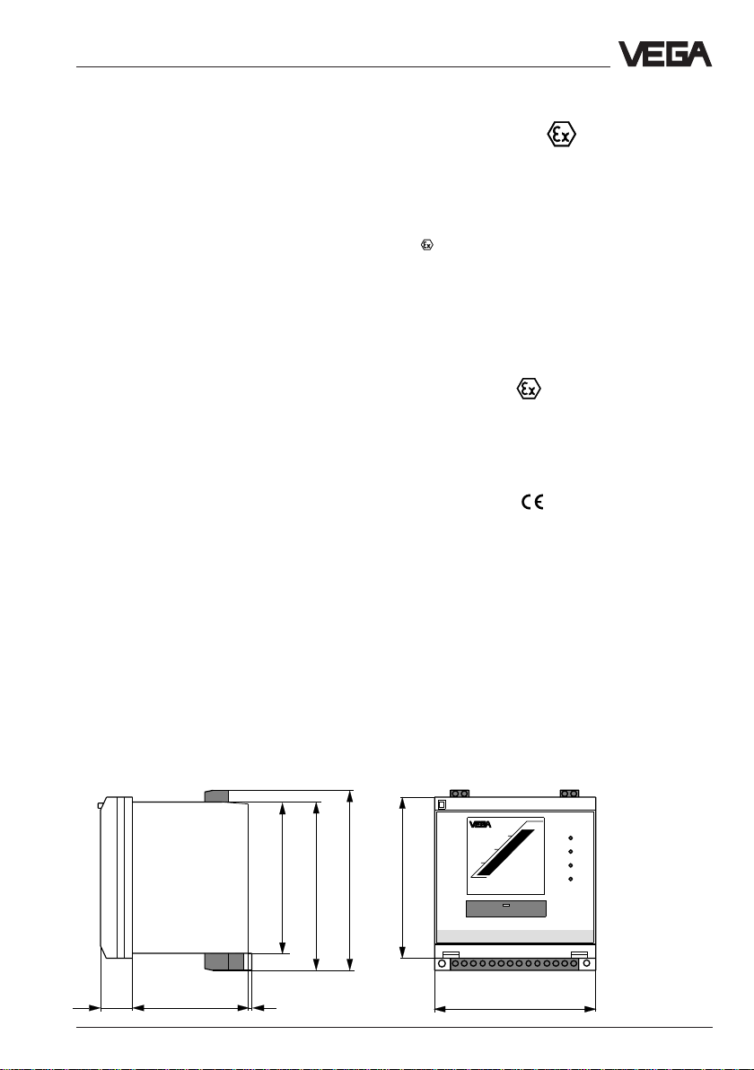
1.4 Dimensions
92
102
19
VEGADIS 371 Ex 3
69
2
109
96
16.85
VEGADIS 371 EX
96
Page 4

1.5 Technical data
General
Series instrument for front panel or wall mounting or
Dimensions W = 96 mm, H = 104 mm, D = 90 mm
Weight approx. 400 g
Housing material plastic ABS/POM
Cross section area of conductor max. 2,5 mm
Ambient conditions
Permissible ambient temperature -20°C … +60°C
Storage and transport temperature -40°C … +85°C
Temperature error 0,01 %/K
Electrical protective measures
Protection class II
Overvoltage category II
Protection
- wall or carrier rail mounting IP 20
- front panel mounting IP 40
V oltage supply
Supply voltage 20 … 250 V AC/DC
Power consumption 4 W, 12,5 VA
Sensor input (floating)
Transmission analogue
Connection line to the sensor 2-wire
I
active
- sensor supply 25 … 15 V (range 4 ... 20 mA)
- shortcircuit limitation approx. 30 mA
I
passive
- inner resistance < 250 Ω (range 4 ... 20 mA)
U
- inner resistance > 100 kΩ (range 0 ... 10 V)
Current output 0/4 … 20 mA (signal circuit, floating)
Resolution 0,1 % (range 0/4 ... 20 mA)
max. load 500 Ω
Fault signal approx. 22 mA
Linearity error 0,1 %
Relay output
Number of relays 4 (2 modules with 2 relays each)
Turn-on voltage min. 10 mV
Switching current min. 10 μA
Breaking capacity max. 54 W DC, 500 VA AC
Indication of switching condition LED lights - relay energized
Digital indication
Zero point (4 mA or 0 V) -9999 … 9999
Final point (20 mA or 10 V) -9999 … 9999
Decimal point individually selectable
mounting on rail 35 x 7,5
2
max. 250 V AC, 250 V DC
max. 3 A AC, 1 A DC
LED off - relay deenergized
Product description
4 VEGADIS 371 Ex
Page 5
Mounting
2 Mounting
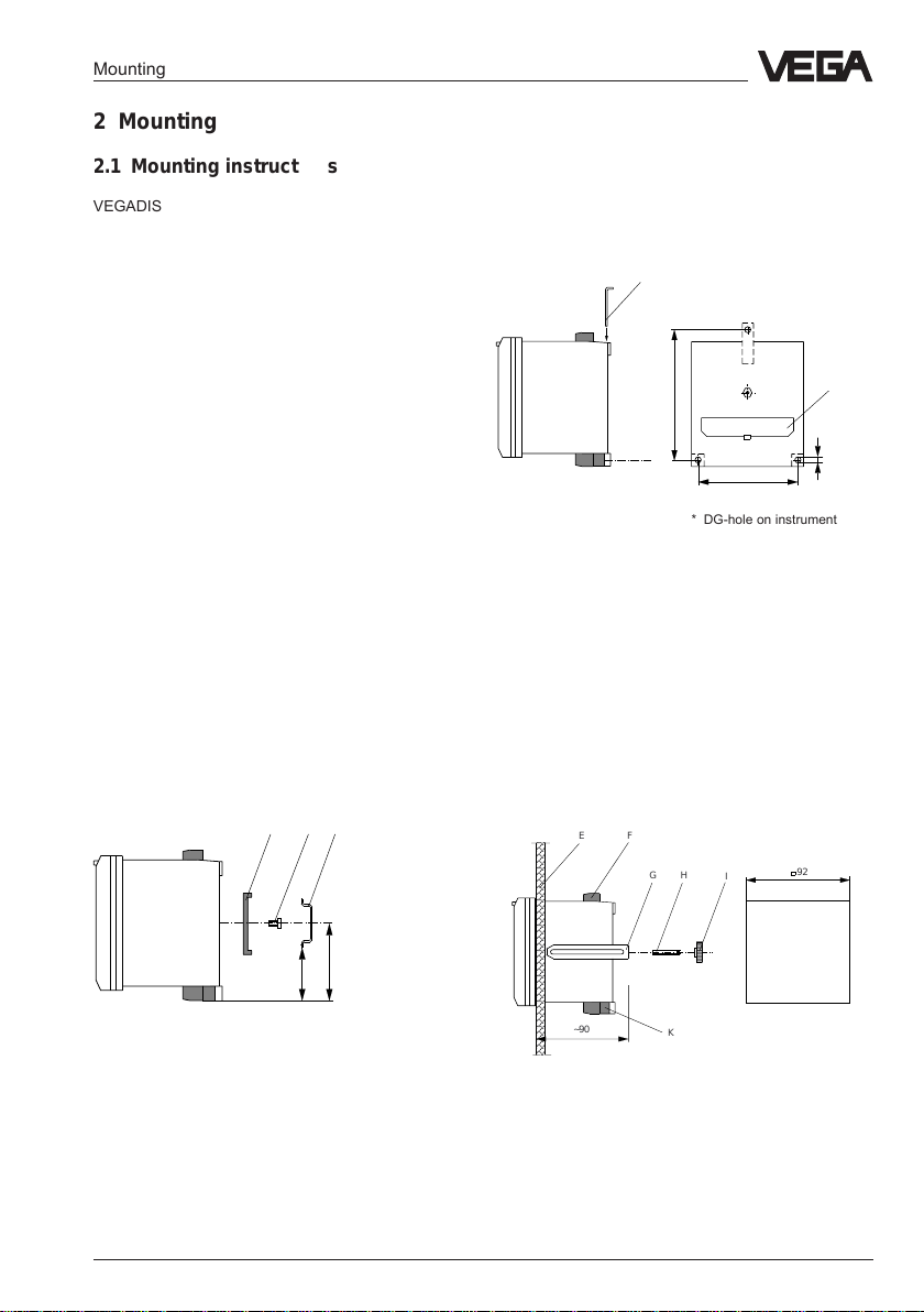
2.1 Mounting instructions
VEGADIS 371Ex indicating instrument can be either
mounted directly to the wall with three screws, plugged
on carrier rail 35 x 7,5 acc. to DIN EN 50 022 or
lowered into a front panel. VEGADIS 371Ex must be
generally mounted outside hazardous areas.
Before mounting VEGADIS 371 you should adjust the
requested sensor signal (Ia, Ip, U). The slide switch on
the rear of VEGADIS 371 under the cover is no more
accessible after mounting the instrument.
Dependent on the application and the sensor you can
choose between active current measurement (Ia),
passive current measurement (Ip) or voltage
measurement (U). Factory setting "Ia“ see also
"4.2 Adjustment“. The position of the switch also
modifies the application conditions for Ex-instruments
(VEGADIS 371Ex). Note the type approval or the
conformity certificate of VEGADIS 371Ex.
Carrier rail mounting
• Place the adapter plate (A) to the rear of VEGADIS
371 (spring of the adapter plate to the bottom) and
tighten the plate with screw B (M4 x 6).
• Place VEGADIS 371 from the bottom to the carrier
rail (C) and push the instrument to the top until
snap-in.
Wall mounting
• Insert the metal sleeve (D) from top into the housing
cut-out.
• Fasten the instrument with three screws (ø max.
4 mm) directly to the wall.
D
105
80
* DG-hole on instrument
Cover
Ø4,5*
Front panel mounting
• Remove the two pluggable terminal boards (F) and
the terminal board (K) to the top.
• Screw the pin (H) to the rear of VEGADIS 371 and
tighten with a screwdriver.
• Insert VEGADIS 371 from the front into the front
panel (E).
• Push the terminal strap (G) from the back to the pin
(H) and pull with the knurled nut (I) against the front
panel (E).
BC
A
61
43,5
EF
~90
H
G
I
K
92
Front panel
cut-out
VEGADIS 371 Ex 5
Page 6

3 Electrical connection
3.1 Sensor connection
Note
Switch off the voltage supply before starting
connection work.
Electrical connection
Active operation (Ia)
+-
Voltage
supply
Passive operation (Ip)
+-
1)
4 ... 20 mA
Sensor
1)
4 ... 20 mA
+
output
-
Sensor
Signal conditioning
instrument
VEGAMET
Voltage
supply
1) Active or passive operation selectable with slide switch.
See “4.1 Indicating and adjustment elements“
6 VEGADIS 371 Ex
Page 7

Electrical connection
3.2 Sensor connection Ex-area
Note:
When using VEGADIS 371 the connection of an iasafety barrier type 145 is not possible. For the use on
sensors in hazardous areas, use VEGADIS 371 Ex.
VEGADIS 371 Ex must be generally mounted outside
hazardous areas.
Active operation (Ia)
Signal and supply circuit
(sensor is powered, 4 … 20
mA)
+-
Voltage
supply
Passive operation (Ip)
Active intrinsically safe signal circuit
4 ... 20 mA
+-
1)
Ex-area
4 ... 20 mA
Intrinsically safe,
passive sensor, e.g.
pressure transmitter
1)
Ex-area
VEGAPULS 81 E Ex
4 ... 20 mA
+
output
-
Voltage
supply
Voltage
supply
1) Active or passive operation selectable with slide switch.
See “4.1 Indicating and adjustment elements“
VEGADIS 371 Ex 7
Page 8

Electrical connection
3.3 Terminal coordination
Meas. data input
-
+
2
1
16.85
18171615 141312 11 10 9 876 5
Relay
Rel.
4
Relay
module 2
Relay
2
Relay
module 1
Relay
1
3
Current output
-
+
4
3
N- L1+
Voltage
supply
3.4 Ex-separating chamber
When several instruments are mounted in a row, the
blue Ex-separating chamber must be plugged to the
terminals of the sensor input (terminals 1 and 2) on
VEGADIS 371 Ex, to ensure the required distance
(50 mm).
• Place the Ex-separating chamber acc. to the figure
to the terminals of the sensor input (terminals 1 and
2) and loop the sensor line to the front out of the Exseparating chamber.
• Push the Ex-separating chamber to the front until
snap-in.
When switching on voltage supply, the software
version of VEGADIS 371 is displayed for approx.
4 seconds.
Tipp:
For parameter adjustment of connected HART
sensors, sockets are integrated in the terminals of the
meas. data input. A VEGACONNECT can be
connected directly to these sockets without an additional HART resistor being necessary.
8 VEGADIS 371 Ex
Page 9

Set-up
4 Set-up
4.1 Indicating and adjustment elements
8
7
1
6
5
1 Slide switch
2 Relay control lamps (1 … 4)
3 Plus key
4 Minus key
5 Cover
6 Shackle
7 Rotating switch
8 Digital indication
2
3
Fig. 4.1
4
The figures in brackets relate to the information in
figure 4.1.
To open the cover (5), insert a screwdriver into the two
slots marked with arrows.
Turn the screwdriver by a quarter turn and the cover
(5) opens.
To protect the instrument against unauthorized
adjustment, the cover (5) of VEGADIS 371 can be
sealed. Insert the seal wire with closed cover in the top
left corner through the hole of the lug.
Designation:
In practise it has proven to mark VEGADIS. Information on the appropriate measurement loop and the unit
of the indicated value help to avoid failures and
misunderstandings. On the housing a shackle (6) is
provided for designation. Here you can insert one of
the supplied labels.
VEGADIS 371 Ex 9
Page 10

Set-up
Rotating switch (7)
Stage 1
In menu stage 1 you find all necessary functions which
are necessary for adjustment of the indicating
instrument. When you are in menu stage 1, the
"VEGA“-logo is shown non-flashing.
Note
When you want to activate the pump changeover
function, all relay outputs you want to coordinate to the
pump changeover function must have the same
function. When relay 1 e.g. switches on when the
adjusted max. value is reached, all following relays
must have the same adjustment.
0 - OPERATE = Indication measured value
1 - Relay 1 on = Relay 1 on
2 - Relay 1 off = Relay 1 off
3 - Relay 2 on = Relay 2 on
4 - Relay 2 off = Relay 2 off
5 - Relay 3 on = Relay 3 on
6 - Relay 3 off = Relay 3 off
7 - Relay 4 on = Relay 4 on
8 - Relay 4 off = Relay 4 off
9-t
i
A - Out 0 … 20 mA,
Out 4 … 20 mA = Current output
B - Display min = Scaled indication at 0 %
C - Display max = Scaled indication at 100 %
D - Decimal point = Decimal point
E - Offset correction = Offset correction
F - Simulation = Simulation
Stage 2
In menu stage 2 you find the functions which are
necessary for adjustment of the pump changeover
function.
In rotating switch position 0 (Operate) you have to
push the plus and minus key together for approx. 3
seconds to change to menu stage 2 (pump
changeover function). When you are in menu stage 2,
the "VEGA“-logo flashes on the display. Push again
both keys to return to menu stage 1. After approx. 10
minutes the indication changes automatically to menu
stage 1.
= Integration time
With the rotating switch (16 steps) you choose the
appropriate function.
0 - OPERATE = Indication of meas. value
1 = Pump changeover function Relay 1 on/off
2 = Operating time indication Rel 1
3 = Pump changeover function Relay 2 on/off
4 = Operating time indication Rel 2
5 = Pump changeover function Relay 3 on/off
6 = Operating time indication Rel 3
7 = Pump changeover function Relay 4 on/off
8 = Operating time indication Rel 4
9 = ---- (not coordinated)
A = ---- (not coordinated)
B = ---- (not coordinated)
C = ---- (not coordinated)
D = ---- (not coordinated)
E = ---- (not coordinated)
F = ---- (not coordinated)
Plus/Minus keys (3 and 4)
With these keys you modify the value of the digital
indication. When you keep the key pushed, the digital
indication changes its value with raising speed.
Slide switch (1)
With the slide switch on the rear of the instrument you
can changeover between voltage measurement, active
sensor input and passive sensor input.
Ia - Active operation: The sensor is powered by
VEGADIS 371. Sensors connected in this
configuration are called passive sensors.
VEGADIS 371 reacts like a current source.
Ip - Passive operation: VEGADIS 371 is connected to
the sensor line (current input 4 … 20 mA). Sensors connected in this configuration are called
active sensors. VEGADIS 371 reacts like a
current sink.
U - VEGADIS measures the voltage 0 … 10 V
Note
The position of the switch changes also the application
conditions for Ex-instruments (VEGADIS 371 Ex).
Also note the type approval or the conformity
certificate of VEGADIS 371 Ex.
10 VEGADIS 371 Ex
Page 11

Set-up
4.2 Adjustment
Stage 1
When switching on the voltage supply, the LED of the
relays shortterm light and the display indicates for
approx. 4 seconds the software version of VEGADIS
371.
The figures in brackets relate to the figure under 4.1
Indicating and adjustment elements.
Course
• Choose the requested mode with the rotating switch
(7).
• Push one of the two keys (3 or 4). The digital
indication (8) begins to flash.
• Push one of the two keys to change the value of the
digital indication appropriately. When the rotating
switch (7) is set to "OPERATE“, the keys (3 and 4)
are without function.
• You can save the adjusted value by changing the
position of the rotating switch (7).
Example
- an upright cylindrical (linear) tank with a content of
2700 l.
- the max. volume is 2650 l, the min. volume 50 l.
- the level sensor in the vessel is a pressure
transmitter (passive), providing a standardized
4 … 20 mA-signal.
- for further processing you need an additional
4 … 20 mA-output signal.
- the full and empty adjustment had been carried out
correctly. The sensor delivers the following values:
Max. volume (display max.)
20 mA = 2650 l
Min. volume (display min.)
4 mA = 50 l
- relay 1 should switch on an emptying pump at a
volume of 90 % and switch off the pump at a volume
of 10 %.
First choose the parameters of your application:
Slide switch
• loosen the cover on the rear of VEGADIS 371 with a
screwdriver. Under this cover there is a slide switch
(1) by which you can adjust the kind of input:
I
= active current input (Ia)
active
I
= passive current input (Ip)
passive
U = voltage measurement (U)
For the given example choose Ia (active current
input).
Current output
• Set the rotating switch (7) to position A. With the
keys (3 and 4) you can choose between measured
value output 4 … 20 mA or 0 … 20 mA.
For the given example choose 4 - 20.
The display indications have the following meaning:
0 - 20 = 0 … 20 mA; 4 - 20 = 4 … 20 mA
VEGADIS 371 requires for the scaling of the indication
the adjustment of the volumes for 4 mA and 20 mA.
The vessel must not be filled or emptied. Proceed as
follows to adjust the two values:
Decimal point
VEGADIS 371 requires for this example the
adjustment of the values for 4 mA and 20 mA (0 % and
100 %). As the range of the example tank is from 50 l
to 2650 l, you require all four positions of the digital
indication.
• Set the rotating switch (7) to position D (Decimal
Point).
• By pushing the keys (3 and 4) you move the
decimal point.
Scaled indication at 0 %
• Set the rotating switch (7) to position B (Display
min.).
• Push the plus key (3) to increase the indicating
value or the min. key (4) to reduce the indicating
value (0,1 %-steps).
• When you keep the key pushed, the digital
indication (8) changes the indicating value quicker.
For the given example adjust the digital indication
(8) to the value 50.
Scaled indication at 100 %
• Set the rotating switch (7) to position C (Display
max.).
• Push the plus key (3) to increase the indicating
value or the minus key (4) to reduce the indicating
value (0,1 %-steps).
• For the given example set the digital indication (8) to
the value 2650.
Relay
• Set the rotating switch (7) to position 1 (relay 1 on).
When the selected relay is not mounted, four
dashes appear on the digital indication. With the
keys (3 and 4) you can modify the value of the
indication. For the given example set the digital
indication (8) to the value 90,0 (90,0 %). Hence the
internal relay 1 switches on when this value is
reached.
VEGADIS 371 Ex 11
Page 12

• Set the rotating switch (7) to position 2 (relay 1 off).
With the keys (3 and 4) you can change the value of
the indication. For the given example you set the
digital indication (8) to the value 10,0 (10,0 %).
Hence the internal relay 1 switches off when this
value is decreased. The appropriate relay control
lamp (2) lights when the relay is energized. When
the switch points are too close together (< 0,1 %),
the appropriate LED flashes. The relay takes the
safe condition. In mode "Operate“ a fault signal is
displayed.
• When you want to control further relays, proceed in
the same way than for relay 1.
The positions for adjustment of the appropriate
relays are stated in the list of the rotating switch (7)
under 4.1 Indicating and adjustment elements.
Mode A
Set-up
Level
Mode A (B)
off (on)
on (off)
t
LED
Relay on
Relay off
Note
When you want to change the mode (i.e. the switching
function of the relays) you have to exchange the on
and off-values (see fig. 4.2)
• Mode A (overfill protection)
switch on point < switch off point
To adjust e.g. for relay 1 mode A (overfill protection)
you have to enter with position 1 (relay 1 on) of the
rotating switch (7) the lower value and with position
2 (relay 1 off) the higher value. Hence relay 1 is
switched off when the max. level is reached
(deenergized condition) and switched on when min.
level is reached.
• Mode B (dry run protection)
switch on point > switch off point
When you want to adjust mode B (dry run
protection) for relay 1, you have to enter with
position 1 (relay 1 on) of the rotating switch (7) the
higher value and with position 2 (relay 1 off) the
lower value. Hence relay 1 is switched on when
Mode B
Relay on
Relay off
Fig. 4.2
max. level is reached and switch off (deenergized
condition) when min. level is reached.
Integration time
• When you want to adjust an integration time
(reaction delay), set the rotating switch (7) to
position 9.
• With the keys (3 and 4) you can change the value of
the indication (0 up to 250 seconds).
Offset correction
As a factory setting, pressure transmitters are adjusted
in a certain position. When the transmitter is
mounted in another position, the measuring range is
shifted.
• Ensure that the sensor is unpressurized.
• To carry out an offset correction, set the rotating
switch (7) to position E (Offset correction). The
display now indicates the actual sensor current in
mA or the voltage in V.
• Push the plus and minus key (3 and 4) together.
The measuring range is not modified, but
completely shifted.
• Set the rotating switch (7) to position 0 (OPERATE).
All adjusted values are transferred to an EEPROMmemory and saved. They remain there even in case
of a probable voltage loss.
12 VEGADIS 371 Ex
Page 13

Set-up
Stage 2
Activation of the pump changeover function
It is the task of a pump changeover function, in case of
several pumps with the same function, to switch on the
pump with the shortest working time and to switch off
the pump with the longest working time.
This avoids overstress of the pumps and the lifetime of
the pumps is increased considerably. This increases
the reliability of the complete system and avoids
failures.
This means that all relays where a pump changeover
function is activated, are no more fixed coordinated to
a certain switch point but are switched on or off
dependent on the working time. VEGADIS 371 Ex
selects for switch on the relay with the shortest
working time and for switch off the relay with the
longest working time.
Example (see fig. 4.3)
Two emptying pumps should empty a vessel when a
certain level is reached. The first pump should switch
on at 80 % filling.
When the level increases, a second pump should be
switched on at 90 %.
Both pumps should be switched off again at 10 %
filling.
€ Enter the values of the concerned relays in stage 1
as follows:
1 Relay 1 on = 80,0
2 Relay 1 off = 10,0
3 Relay 2 on = 90,0
4 Relay 2 off = 10,0
€ Set the rotating switch to position 0
(Operate).
€ Change to the menu stage 2, where you push the
plus and the minus key together for approx. 3
seconds. The "VEGA“-logo flashes on the display.
€ Set the rotating switch to position 1 (pump
changeover function relay 1)
€ Set the indication with one of the two keys to "on“.
€ Set the rotating switch to position 3 (pump
changeover function relay 2)
€ Set the indication with one of the two keys to "on“.
€ Set the rotating switch to position 0
(Operate) and push the plus and minus key together
for approx. 3 seconds. The "VEGA“-logo no more
flashes. The pump changeover function is now
Level
Füllhöhe
On2
90%
On1
80%
Off1
0%
Off2
On
Relay 1
Off
On
Relay 2
Off
10 30 20 20 5 15
t [h]
Fig. 4.3
VEGADIS 371 Ex 13
Page 14

Set-up
Indication of the working times
When the pump changeover function of a relay is
activated, the working times can be enquired (positions
of the rotating switch 2, 4, 6, 8)
The working times of the relays which are coordinated
to the pump changeover function are saved every 8
hours in the EEPROM, i.e. the data saved last remain
even in case of power failure.
The working time is indicated in hours. The max.
indication is 9999 hours (over 1 year). If this value is
exceeded, the working time indication starts again at
0.
When you deactivate the pump changeover function of
a relay, the working time indication is set to 0 and
switched off.
When you carry out a reset, the pump changeover
function for all relays is deactivated and the working
time indication of all relays is reset to 0.
You can add or remove each relay individually to/from
the pump changeover function. Any combination is
possible.
The coordinated relays must all be operated in the
same mode (A/B):
Mode A (overfill protection)
Switch on point < Switch off point
Switch on relay:
The relay with the shortest working time
switches on.
Switch off relay :
The relay with the longest working time
switches off.
Mode B (dry run protection)
Switch on point > Switch off point
Switch on relay:
The relay with the shortest working time
switches on.
Switch off relay:
The relay with the longest working time
switches off.
realised for both pumps (relay 1 and 2).
4.3 Mounting of the relay modules
Up to 2 relay modules with 2 output relays each can be
mounted in VEGADIS 371. The mounting should be
made by skilled staff. Ex-approved instruments must
not be modified afterwards. When you want to retrofit
VEGADIS 371 Ex, send the instrument to VEGA. With
two relay modules totally 4 output relays are available.
• Switch off voltage supply.
• Loosen the front of the housing of VEGADIS 371
with a coin or a screwdriver. On the lower side of
the housing there is a slot.
• Remove the front of the housing. You do not have to
loosen the connection cable of the digital indication
to mount the relay modules.
• Plug the first relay module carefully to module 1.
Note that the pins are not bent (see fig. 4.4).
• Fasten the relay module with a small screwdriver.
• A sticker is attached to the relay where the terminal
coordination is visible. Place this sticker to the
instrument housing in front of the appropriate
terminals.
• Connect the terminals of the relays.
• Switch the supply voltage on.
• Adjust the switch points so that you can use the
Note
The cover is lockable to protect the instrument against
unauthorized adjustment.
Fig. 4.4
14 VEGADIS 371 Ex
Page 15

Set-up
relay module (see "4.2 Adjustment“).
4.4 Reset
You can carry out a reset on VEGADIS 371. Hence all
adjusted values are reset to the original factory setting.
• Interrupt the supply voltage of VEGADIS 371.
• Push the plus and minus key (3 and 4) together and
hold the two keys pushed. Switch on the supply
voltage. The display indicates "-RES-“. The
instrument carries out a reset.
VEGADIS 371 has the following fatory setting (ResetDefault values).
Factory setting
Menu stage 1
- Relay switch on points (10,0 %)
- Relay switch off points (100,0 %)
- Display min. (0)
- Display max. (100)
- Decimal point (1. position)
- Integration time (0 s)
- Offset correction (0 μA)
- Current output (4 … 20 mA)
Menu stage 2
- Pump changeover function (OFF)
- Working time indication (0 hours)
VEGADIS 371 Ex 15
Page 16

Diagnosis
5 Diagnosis
5.1 Simulation
The figures in brackets relate to the figures under "4.1 Indicating and adjustment elements“.
• Set the rotating switch (7) to position F "Simulation“. The actual measured value is taken over and flashes. The
simulation is immediately active. Level changes are not indicated during simulation.
• With the keys (3 and 4) you can modify the value of the indication. You can adjust any requested value within
the scaled range and hence test also the function of the current output and the mounted output relays.
• After the simulation is finished, you have to set the rotating switch (7) again to position 0 “OPERATE“. Hence
the simulation is interrupted and the actual measured value is indicated again.
5.2 Fault signals
The following fault signals can be indicated on the display:
Fault signal/Failure Removal/Measure
E003 Failure during selfcheck Relays deenergize (safe condition), current output 22 mA.
E014 Shortcircuit Relays deenergize (safe condition), current output: 22 mA.
E015 Line break Relays deenergize (safe condition), current output: 22 mA.
E017 Relay switch points The LED of the concerned relay flash.
Difference too small The concerned relay deenergizes (safe condition).
E021 Indication scaling Repeat the adjustment "4.2 Adjustment“.
Difference too small Increase the difference between the two indication values.
E116 Pumps in different The LED of the concerned relay flashes.
mode The concerned relay deenergizes (safe condition).
Carry out a reset (see 4.4 Reset). Hence all adjusted values are reset to
factory setting.
When the failure occurs again, send the instrument to our repair
department.
Sensor current > 21 mA.
Check the terminals and the connection line to the sensor.
Sensor current < 3,6 mA.
Check the terminals and the connection line to the sensor.
Probably no sensor connected.
Repeat the adjustment "4.2 Adjustment“.
Increase the difference between the two relay switch points.
Change to menu stage 1.
Check the switching function of relay 1.
Set all relays which are used for pump changeover function to the same
switching function like relay 1 or deactivate the pump changeover
function for these relays.
16 VEGADIS 371 Ex
Page 17

Notes
VEGADIS 371 Ex 17
Page 18

Notes
18 VEGADIS 371 Ex
Page 19

Notes
VEGADIS 371 Ex 19
Page 20

VEGA Grieshaber KG
Am Hohenstein 113
D-77761 Schiltach
Phone (0 78 36) 50 - 0
Fax (0 78 36) 50 - 201
e-mail info@de.vega.com
ISO 9001
The statements on types, application, use and operating conditions of the
sensors and processing systems correspond to the actual knowledge at the
date of printing.
Technical data subject to alteration
19893-EN-060426
 Loading...